1
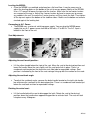
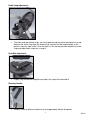
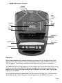
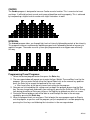
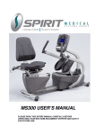
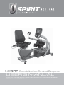
MS300 Rehabilitation Seated Stepper
USER’S MANUAL
PLEASE READ THIS ENTIRE MANUAL CAREFULLY BEFORE OPERATING YOUR NEW SEMI-RECUMBENT
STEPPER AND SAVE IT FOR FUTURE USE.
Table of Contents
Product Registration………………………………………………………………………….
2
Important Safety Instructions…………………………………………………………………
3
Important Electrical Information………………………………………………………………
4
Important Operation Instructions……………………………………………………………..
4
Features………………………………………………………………………………………..
5
Operation of Your New Stepper…………………………………………………….….……
8
MS300 Assembly Instructions……………………………………………………………….
17
MS300 Drawing & Parts List…………………………………………………………………
23
Maintenance……………………………………………………………………………………
30
Specifications…………………………………………………………………………………..
31
Manufacturer’s Limited Warranty……………………………………………………………..
32
1
MS300
Thank you for your recent purchase of this high quality Semi-Recumbent Seated Stepper, the
MS300, from Spirit Medical Systems Group.
Your new product was manufactured by one of the leading fitness and medical products
manufacturers in the world. Further, it is backed by one of the most comprehensive warranties in
the industry. Through our dealers, distributors and manufacturer’s representatives, we will do all
we can to provide many years of successful and prosperous ownership. Your warranty and service
needs will be addressed collaboratively through your regional sales representative and our highly
trained service technicians.
The responsibility of that collaborative team is to provide you with both the technical knowledge
and access to service personnel to make your ownership experience more informed, and
resolution of any difficulties easier to remedy.
Two components of the Spirit Medical Systems Group’s mission statement are “enhancing patient
outcomes and improving effectiveness in the delivery of services”. This is just one of the many
products that will assist you in providing that care to your patients and/or clients.
Please take a moment at this time to record the name of the dealer, distributor, or
manufacturer’s representative, their telephone number, and the date of purchase below to
make any future, needed contact easy. We appreciate your support and we will always
remember that you are the reason that we are in business.
Please complete and mail your registration card today and enjoy your new MS300.
Yours in Health and Wellness,
Spirit Medical Systems Group
Product Registration
RECORD YOUR SERIAL NUMBER
Please record the Serial Number of this fitness product in the space provided below. You can
find the serial number on a sticker that is located on the front left side of the product.
Serial Number_______________________________________
REGISTER YOUR PURCHASE
The self-addressed product registration card must be completed in full and returned to
Spirit or visit: www.spiritmedicalsystems.com to register online.
2
MS300
Important Safety Instructions
■
■
■
■
■
■
■
■
■
■
■
■
■
■
■
ATTENTION - Read all instructions in this manual before using this device.
DANGER - To reduce the risk of electric shock disconnect the product from the
electrical outlet prior to cleaning and/or service work.
WARNING - To reduce the risk of burns, fire, electric shock, or injury to persons, install
the unit on a flat level surface with access to a 110 to 230-volt AC, 50/60 Hz, 15-amp
outlet. The unit should be the only appliance in the electrical circuit.
Use this device only for it’s intended use as described in this manual.
Keep children away from the device. There are moving parts, obvious pinch points and
other caution areas that can cause harm.
Except as instructed for use of the device, keep hands away from all moving parts.
Keep the electrical cord away from heated surfaces and out of all travel lanes and do not
operate the device if the cord or plug is damaged.
Never drop or insert any object into any openings.
Do not use outdoors.
To disconnect, turn all controls to the off position then remove the plug from the outlet.
This device is designed for commercial use and will meet the demands of orthopedic,
sports wellness and general conditioning programs.
Do not attempt to use the device for any purpose other than for the purpose it is intended.
The pulse sensors are not medical devices. Various factors, including the user’s movement,
may affect the accuracy of heart rate readings. The pulse sensors are intended only as
exercise aids in determining heart rate trends in general.
WARNING: Heart rate monitoring system may be inaccurate. Over exercise may result in
injury or death. If you feel faint stop exercising immediately.
Ensure there is a minimum space on the sides of the unit of two feet for proper operation, easy
access and to prevent possible injuries to others standing or walking nearby. There should be a
minimum of at least one foot of free space at the front and rear of the unit.
Do not use any after market parts on this device, other than those recommended by Spirit.
Do not attempt any servicing or adjustments other than those described in this manual. All
else must be left to trained service personnel familiar with electro-mechanical equipment
and authorized under the laws of the country in question to carry out maintenance and
repair work.
To avoid injury please observe all minimum and maximum seat and arm adjustment
settings.
Important Electrical Information
WARNING!
NEVER remove any cover without first disconnecting AC power. If voltage varies by ten percent
(10%) or more, the performance of your bike may be affected. Such conditions are not
covered under your warranty. If you suspect the voltage is low, contact your local power
company or a licensed electrician for proper testing.
NEVER expose this product to rain or moisture. This product is NOT designed for use
outdoors, near a pool or spa, or in any other high humidity environment. The temperature
specification is 40 degrees c (104 deg f), and humidity is 95%, non-condensing (no water
drops forming on surfaces).
3
MS300
Important Operation Instructions
●
●
●
●
NEVER use the device during an electrical storm. Surges may occur in your facility
power supply that could damage the unit’s components.
All users should have medical clearance before starting any rigorous exercise
program.
Start the user at a safe exercise level. Do not allow the user to be over exerted.
Symptoms to watch for, but not limited to, are: Shortness of breath or difficulty in
breathing, pain or discomfort, feeling faint.
Make sure the user warms up and cools down properly to avoid over taxing the
cardio vascular system. Allow three to five minutes of warm up and cool down
during each exercise session.
4
MS300
Features
MS300– Rehabilitation Seated Stepper
Parts and Adjustments:
1.
2.
3.
4.
5.
6.
7.
Optional Parts (not shown):
Electronic Console
Upper Body Rotating Handles
Handle Length Adjustment
Cushioned Footplates with straps
Swivel Seat with seat belt
Lifting Handle for transport
Leveling Glides
Wrist cuffs
Calf Supports
The Spirit MS300 is an easy product to set up and use, from the adjustments to the intuitive
interface. This section explains how to set up, adjust and operate your MS300 from Spirit Medical
Systems Group.
5
MS300
Leveling the MS300:
• Once the MS300 is assembled, and placed on a flat level floor, it may be necessary to
adjust the leveling glides on the bottom of the unit to ensure proper stability of the MS300.
Use a 1/2” wrench to loosen the top nut of the levelers. Make sure the two center levelers
are screwed all the way in. Adjust the 4 corner levelers by hand as necessary to remove
any wobble in the unit. Unscrew the 2 center levelers until they touch the floor. Then tighten
all the top nuts against the bottom of the stabilizer tubes. Make sure the bottom nut remains
cinched against the leveling foot.
Connecting to A.C. Power:
• The MS300 uses a universal switching power supply. You can plug the MS300 power
supply into any A.C. power source from 90 to 260 volts, 47 to 63 Hz. The A.C. input is
located in the front of the unit.
Seat Adjustments:
Adjusting the seat fore/aft position:
• Lift the yellow handle below the front of the seat. Move the seat to the desired position and
lower the handle. Move the seat slightly until the seat lock clicks in place. There is a
numbered scale located on the aluminum seat slide tube for repeatable settings. Seat
position is indicated by the front of the seat carriage lining up with the number on the scale.
Adjusting the seat back angle:
• To adjust the seat back angle, squeeze the brake handle located on the right side handle
bar and move the seat back to the desired position. There is a numbered scale located just
below the seat back cushion for repeatable settings.
Rotating the swivel seat:
• Lift the handle behind the seat to disengage the latch. Rotate the seat to the desired
position; lower the handle when approaching position to activate latch. The seat will latch
into place every 45 degrees
6
MS300
Pedal strap adjustment:
• The ankle and foot Velcro straps are easily opened and closed for quick patient set up.
Remove the ankle strap from the chrome ring. Loosen the foot strap enough so the
patient’s foot can slide under. Once the foot is in the correct position reattach the ankle
strap and adjust both straps for a snug fit.
Seat Belt adjustment:
• Simply snap the buckles together and adjust the strap to the desired fit.
Rotating Handle:
•
Handles rotate to allow wrist patients to use upper body without discomfort.
7
MS300
• MS300 Electronic Console:
Muscle
Activation
Display
Data
Displays
HR
Percent
Profile
Graphic
Display
Message
Window
Cooling Fan
Program Keys
Set Up Key
Function Keys
Power on
When initially powered on the console will perform an internal self-test. During this time all the
lights will turn on for a short time. The message window will then show a software version (i.e.
VER 1.0) and the Time window will display the total hours the unit has been used to date.
The odometer will remain displayed for only a few seconds then the console will go to the start up
display, also known as Idle Mode. The dot matrix display will be scrolling through the different
program profiles and the message window will be scrolling the start up message. You may now
begin to use the MS300.
The console will automatically power down after 20 minutes of inactivity. Press any key to wake
the console up again. Always disconnect the main power when the MS300 is not in use.
8
MS300
Console Operation:
1. Set Up Key
The Set Up key function will allow you to set seat and arm adjustments for various patient heights
and customize the settings of the MS300. When the Set Up key is pressed the first option in the
menu appears. Use the up/down arrows to scroll through the menu and press the enter key to
select an option.
Set Up menu:
Position (seat and arm position setting):
User may input their height in inches (or centimeters if unit is set to metric measurements, see
page 30) and the software will calculate the position for the seat and arms. This feature is
intended to aid in patient set up but may not be the final settings as patient’s body symmetry
may vary slightly.
Track or Step graph
The segmented track surrounding the profile display area can be set to display as a track or a
foot position indicator. During any program press the Symmetry key to switch the display.
2. Quick Start
This is the quickest way to start an exercise session. After the console powers up you just press
the Start key to begin; this will initiate the Quick Start mode. In Quick Start, the Time will count up
from zero, all workout data will start to accrue and the workload may be adjusted manually by
pressing the Up or Down key. The dot matrix will display a workload level at the lowest resistance.
As you increase the workload more rows will light indicating a harder workout. The unit will get
harder to pedal as the rows increase.
The graphic display has 20 columns of lights with each column representing 1 minute in the Quick
Start program (time per column can be modified in other programs). At the end of the 20th column
(or 20 minutes of work) the display will wrap around and restart at the first column again. There
are 20 levels of resistance displayed in 10 rows of lights.
3. Basic information
The Graphics Display (dot matrix) is used for displaying work profiles and the Symmetry graph.
When you begin a program the dot matrix will display a workload profile. The profile indicates the
different resistance level changes during a program. The peak resistance level can be set during
program setup. The peak setting can be adjusted during your workout also. When adjusting the
peak level during a program the profile picture will not change, but the message window will
display your new level setting.
The Data Display windows provide exercise information during a session. Information includes:
SPM (Steps Per Minute), Calories, Time, Steps (total step count) and Pulse. Resistance level and
Watt measurements are displayed on either side of the graphic display.
9
MS300
The Message Window is the main display for programming instructions and relevant
measurements during a program. The measurement data shown varies depending on the program.
Measurements include: Average Watts (Left and Right leg), METs, Symmetry and Segment time.
To the right of the Dot matrix display is a Heart Rate Bar Graph. Simply grasping the hand pulse
sensors, or wearing a heart rate chest belt transmitter, will start the heart rate measurement
function (this may take a few seconds). The Pulse window will display the heart rate in beats per
minute. The Bar Graph represents the percentage of maximum heart rate. NOTE: Enter the
correct age in Set Up for the Bar Graph to be accurate. Refer to Heart Rate section for details
about these features.
The Muscle Activation Display at the top of the console provides a quick look at level of
activation for different muscle groups.
Function Keys:
The Stop/Reset key provides several functions.
• Pressing the Stop/Reset key once during a program will Pause the program. To resume the
exercise session just press the Start key.
• If the Stop/Reset button is pressed twice during a workout the program will end and a
summary of information for the exercise session will be displayed.
• If the Stop/Reset key is held down for 3 seconds the console will perform a complete
Reset.
• During data entry for a program the Stop/Reset key performs a Previous Screen function.
This allows you to go back one step in the programming each time you press the
Stop/Reset key.
The Program Keys may be used to preview each program when in the idle mode. Press each
program key to preview what the program profile looks like. To begin a program press the
corresponding program key and then press the Enter key to select the program.
The program keys also function as a Number Key Pad when you are in the data-setup mode. If
you are entering new data such as Time, Age, weight etc., you can use these keys to enter the
numbers quickly. The Manual key would enter the number 1, Hill key is number 2, etc.
4. Selecting and customizing programs
When you enter a program you have the option of modifying the settings. If you want to begin
without entering new settings just press the Start key. This will bypass the programming of data
and take you directly to the start of the program. If you want to change the settings just follow the
instructions in the message window. If you start a program without changing the settings the data
from the Set Up menu will be used.
Manual
The Manual program works as the name implies, manually. This means that you control the
workload yourself, not the computer. To start the Manual program follow the instructions below or
just press the Manual button then the Enter button and follow the directions in the message
window.
1. Press the Manual key then press the Enter key.
2. The message window will prompt you to enter the Age, Weight and Time for the program.
10
MS300
You may enter the Age using the Up and Down keys or the numeric key pad then press the
Enter key to accept and proceed to the next screen.
3. Now you are finished editing the settings and can begin the program by pressing the Start
key. You can also go back and modify your settings by pressing the Enter key. NOTE: At
any time during the editing of Data you can press the Stop key to go back one level, or
screen.
4. During the Manual program you will be able to scroll through the data in the message
window by pressing the Enter key.
5. When the program ends you may press Start to begin the same program again or Stop to
exit the program, or you can save the program you just completed as a custom program by
pressing the User keys and following the instructions in the message window.
Preset Programs
The Semi-Recumbent Seated Stepper has four preset exercise programs that have been
designed for a variety of workout goals. The initial built-in level of difficulty for each program is set
to a relatively easy level. You may adjust the level of difficulty (Max level) for each program before
beginning.
The profiles shown in the dot matrix are merely pictures of the whole profile and will not change in
size when the work level keys are pressed. When setting up a program you will enter the
maximum resistance setting for the peak of the profile. During the program the resistance levels
will change as the profile progresses. When the level up key is pressed to request more resistance
the profile picture will not change, but the workload will increase. The message window will display
the level setting for the current segment and also the maximum level for the peak of the profile.
Pressing the work keys actually change the peak level of the program not the current segment
level. You may need to change the peak setting several times before the current segment
increases.
HILL
The Hill program simulates going up and down a hill. The resistance in the pedals and upper body
arms will steadily increase and then decrease during the program.
PLATEAU
The Plateau program provides a steady state exercise with warm up and cool down periods.
11
MS300
CARDIO
The Cardio program is designed to increase Cardio vascular function. This is exercise for heart
and lungs. It will build up heart muscle and increase blood flow and lung capacity. This is achieved
by incorporating a higher level of exertion with slight fluctuations in work.
INTERVAL
The Interval program takes you through high levels of intensity followed by periods of low intensity.
This program increases endurance by depleting oxygen levels followed by periods of recovery to
replenish oxygen. The cardio vascular system gets programmed to use oxygen more efficiently
this way.
Programming Preset Programs:
1. Select the desired program button then press the Enter key.
2. The message window will prompt you to enter the Age, Weight, Time and Max Level for the
program. You may enter the Age using the Up and Down keys or the numeric key pad then
press the Enter key to accept and proceed to the next screen.
a. Max Level refers to the top resistance level setting for the program.
3. Now you are finished editing the settings and can begin the program by pressing the Start
key. You can also go back and modify your settings by pressing the Enter key. NOTE: At any
time during the editing of Data you can press the Stop key to go back one level, or screen.
4. During the Manual program you will be able to scroll through the data in the message
window by pressing the Enter key.
5. When the program ends you may press Start to begin the same program again or Stop to
exit the program, or you can save the program you just completed as a custom program by
pressing the User keys and following the instructions in the message window.
12
MS300
User Programs
The User1&2 programs allow you to build and save a custom program. You can build your own
custom program by following the instructions below or you can save any other preset program you
complete as a custom program. The User program allows you to further personalize it by adding
your facility name.
Designing and saving a new program:
1. Press either User key. The message window will show a welcome message; if you had
previously saved a program the message will contain the name you gave it. Then press the
Enter key to begin programming.
2. When you press enter, the message window will show “Name – A”, if there is no name saved.
If the name “Custom Workout” had been previously saved the message window will show
“Name – Custom Workout” and the C in Custom will be blinking. If there is a name saved you
can change it or you may press the Stop key to keep the name and continue to the next step.
If you want to enter a name use the Up and/or the Down key to change the first letter then
press Enter to save the first letter and continue to the next letter. When you have finished
entering the name press the Stop key to save the name and continue to the next step.
3. The message window will ask you to enter an Age. You may enter an Age, using the Up and
Down keys or the numeric key pad, then press the Enter key to accept the new number and
proceed on to the next screen.
4. You are now asked to enter a Weight. You may adjust the Weight number using the Up and
Down keys or the numeric key pad then press enter to continue.
5. Next is Time. You may adjust the Time and press enter to continue.
6. Now you are asked to adjust the Max Level. This is the peak exertion level you will
experience during the program. Adjust the level and then press enter.
7. Now the first column will be blinking and you are asked to adjust the level for the first
segment of the workout. When you finish adjusting the first segment, or if you don’t want to
change, then press enter to continue to the next segment.
8. The next segment will show the same level as the previously adjusted segment. Repeat the
same process as the last segment then press enter. Continue this process until all twenty
four segments have been set.
9. The message window will then tell you to press enter to save the program. After saving the
program the message window says “New program saved” then will give you the option to
Start or modify the program. Pressing Stop will exit to the start up screen.
10. During the Facility program you will be able to scroll through the data in the message window
by pressing the Enter key.
Running a saved program:
1. Press User key then Enter
2. Enter Time then press start to begin program.
13
MS300
Symmetry
The Symmetry program may aid in achieving a more balanced exercise stroke for patients with
bi-lateral deficiencies, such as stroke patients and post-op knee patients. The program will
measure the left and right power through the pedal range. The Dot Matrix display will show a
graph indicating the leg power symmetry so the user has a visual feedback to aid in improving
the involved limb’s strength. The program will also work for upper body only. When pushing the
handles, the graph will be reversed (Left side will actually be displaying right arm information). It
will be correct if the patient is pulling.
1. Press the Symmetry key then press the Enter key.
2. The message window will prompt you to enter the Age, Weight and Time for the program.
You may enter the Age using the Up and Down keys or the numeric key pad then press
the Enter key to accept and proceed to the next screen.
3. Now you are finished editing the settings and can begin by pressing the Start key. You
can also go back and modify your settings by pressing the Enter key. NOTE: At any time
during the editing of Data you can press the Stop key to go back one level, or screen.
4. During the program you will be able to scroll through the data in the message window by
pressing the Enter key.
5. When the program ends you may press Start to begin the same program again or Stop to
exit the program, or you can save the program you just completed as a User program by
pressing a User key and following the instructions in the message window.
Biofeedback Graph:
Below is a sample picture showing the symmetry graph. In the message window there is an
average watt measurement and it is indicating that the left leg is producing more power than the
right leg, 41 vs. 34 watts. The graph reflects the higher wattage of the left leg. If the power is equal
in both legs only two dots would be lit on the bottom center of the graphic screen. Press the Enter
key to view the Symmetry data.
14
MS300
Using a Heart Rate Transmitter
*NOTE: The chest strap transmitter is not a standard part, but is a separate purchase.
How to wear your wireless chest strap transmitter:
1. Attach the transmitter to the elastic strap using the locking parts.
2. Adjust the strap as tightly as possible as long as the strap is not too tight to remain comfortable.
3. Position the transmitter with the logo centered in the middle of your body facing away from your
chest (some people must position the transmitter slightly left of center). Attach the final end of
the elastic strap by inserting the round end and, using the locking parts, secure the transmitter
and strap around your chest.
4. Position the transmitter immediately below the pectoral muscles.
5. Sweat is the best conductor to measure very minute heart beat electrical signals. However,
plain water can also be used to pre-wet the electrodes (2 black square areas on the reverse
side of the belt and either side of transmitter). It’s also recommended that you wear the
transmitter strap a few minutes before your work out. Some users, because of body chemistry,
have a more difficult time in achieving a strong, steady signal at the beginning. After “warming
up”, this problem lessens. As noted, wearing clothing over the transmitter/strap doesn’t affect
performance.
6. Your workout must be within range - distance between transmitter/receiver – to achieve a
strong steady signal. The length of range may vary somewhat but generally stay close enough
to the console to maintain good, strong, reliable readings. Wearing the transmitter immediately
against bare skin assures you of proper operation. If you wish, you may wear the transmitter
over a shirt. To do so, moisten the areas of the shirt that the electrodes will rest upon.
Note: The transmitter is automatically activated when it detects activity from the user’s heart. Additionally, it
automatically deactivates when it does not receive any activity. Although the transmitter is water resistant, moisture
can have the effect of creating false signals, so you should take precautions to completely dry the transmitter after
use to prolong battery life (estimated transmitter battery life is 2500 hours). If your chest strap has a replaceable
battery the replacement battery is Panasonic CR2032.
Erratic Operation:
Caution! Do not use the MS300 for Heart Rate Control unless a steady, solid Actual Heart
Rate value is being displayed. High, wild, random numbers being displayed indicate a
problem.
Areas to look at for interference, which may cause erratic heart rate:
(1) Microwave ovens, TVs, small appliances, etc.
(2) Fluorescent lights.
(3) Some household security systems.
(4) Perimeter fence for a pet.
(5) Some people have problems with the transmitter picking up a signal from their skin. If you have
problems try wearing the transmitter upside down. Normally the transmitter will be oriented so
the Spirit logo is right side up.
(6) The antenna that picks up your heart rate is very sensitive. If there is an outside noise source,
turning the whole machine 90 degrees may de-tune the interference.
(7) If there is another person wearing a chest strap within 1 meter, it will interfere.
(8) If you continue to experience problems contact your dealer.
15
MS300
Heart Rate Program operation
To start the HR program follow the instructions below or just press the HR key then the Enter
button and follow the directions in the message window.
1. Press the HR key then press the Enter key.
2. The message window will ask you to enter your Age. You may enter your Age, using the Up
and Down keys or the numeric key pad, then press the Enter key to accept the new number
and proceed on to the next screen.
3. You are now asked to enter your Weight. You may adjust the Weight number using the Up
and Down keys or the numeric key pad, then press enter to continue.
4. Next is Time. You may adjust the Time and press enter to continue.
5. Now you are asked to adjust the Heart rate Level. This is the heart rate level you will
experience during the program. Adjust the level and then press enter.
6. Now you are finished editing the settings and can begin your workout by pressing the Start
key. You can also go back and modify your settings by pressing the Enter key. NOTE: At any
time during the editing of Data you can press the Stop key to go back one level, or screen.
7. If you want to increase or decrease the workload at any time during the program press the Up
or Down key. This will allow you to change your target heart rate at any time during the
program.
8. During the HR program you will be able to scroll through the data in the message window by
pressing the adjacent Display key.
9. When the program ends you may press Start to begin the same program again or Stop to exit
the program or you can save the program you just completed as a custom user program by
pressing a User key and following the instructions in the message window.
16
MS300
ASSEMBLY INSTRUCTIONS FOR MS300
1) Hardware
STEP 1.
#129- M6 x 40L (2PCS)
#185-5/16" x 19 x 1.5T (4PCS)
#132- 3/8" x 2" (4PCS)
#170-3/8" x 19 x 1.5T (6PCS)
#181-M5 x 15L (12PCS)
#190-3/8" x 7T (6PCS)
#135- 5/16" x 1-1/4" (1PCS)
#173-8.5 x 26 x 2T (2PCS)
#140-3/8" x 3-1/4" (2PCS)
#193-5/16" x 6T (1PCS)
#187-M6 x 6T (2PCS)
STEP 2.
#152-5/16" x 1-3/4" (2PCS)
#170-3/8" x 19 x 1.5T (2PCS)
#193-5/16" x 6T (2PCS)
#153-M8 x 12L (2PCS)
#184-8 x 23 x 1.5T (2PCS)
#154-3/8" x 2-1/2" (2PCS)
#190-3/8" x 7T (2PCS)
#194-3/8" x 2T (2PCS)
17
MS300
STEP 3.
#122-M6 x 25L (4PCS)
#167-10 x 25 x 2T (2PCS)
#190-3/8" x 7T (2PCS)
#197-3/8" x 1-3/4" (2PCS)
STEP 4.
#143-M5 x 12L (4PCS)
#216-3/8" x 5/8" (8PCS)
#217-3/8" x 19 x 1.5T (4PCS)
#218-3/8" x 23 x 2.0T (4PCS)
18
MS300
2) Assembly
STEP 1: PEDALS, SEAT LATCH HANDLE AND HANDLE BAR ASSEMBLY
1. *This section is easier if you slide the seat carriage (20) all the way back before starting.
Slide the handle bar assembly (17) onto the receiving tubes of the seat frame (20). Secure the
handle bar assembly starting with the two 3/8” x 3-1/4” bolts (140) (install from the inside hole
of the receiving tube), two flat washers (170) and nylon nuts (190). Install the safety cover
(108) and seat belts (233) onto bolts before assembling washers and nuts. Install the four
3/8” x 2” bolts (132) from the top side of the tubes and assemble the four 3/8” flat washers
(170) and 3/8” nylon nuts (190).
2. Attach the end of the seat back gas shock (109) to the seat back angle adjustment bracket of
the handle bar assembly (17) using 5/16” x 1-1/4” bolt (135), two 5/16” flat washers (173) and
5/16” nylon nut (193).
3. Assemble swivel seat latch handle (22) to the seat assembly (20) with the two 6mm x 40mm
bolts (129), four 6mm curved washers (185) and two 6mm nylon nuts (187)
4. Plug the hand pulse connectors from the handle bars into the mating connectors of the seat
carriage.
5. Assemble the rubber isolators (82) and pedals (28) to the pedal foot plates with six M5 phillips
screws (181) per side.
6. Press the four stabilizer end caps (31) into the stabilizer tubes. May tap in with a rubber mallet.
19
MS300
STEP 2: CONSOLE MAST & TRANSPORT WHEELS ASSEMBLY
1. Install the transport wheels (77) using the 5/16” x 1-3/4” bolts (152) and 5/16” nylon nuts
(193).
2. Slide the console mast cover (74) onto the console mast (2); be sure the cover orientation
on the mast is correct otherwise it won’t clip in place later.
3. Snake the computer cable through the console mast and slide the mast onto the receiving
brackets. Make sure the cable does not get pinched in between the mast and bracket.
4. Fasten the mast with the two 3/8” x 2-1/2” bolts (154), 3/8” split washers (194) and 3/8” flat
washers (170) from the left side of the mast and secure with the two 3/8” nylon nuts (190).
Install the two 8mm x 12mm bolts (153) and curved washers (184) through the front and
rear holes in the mast.
20
MS300
STEP 3: SEAT BACK AND BOTTOM CUSHION ASSEMBLY
1. Slide the seat back assembly (94) into the seat back angle adjustment bracket and secure
with the two 3/8” x 1-3/4” bolts (197), 3/8” washers (167) and 3/8” nuts (190).
2. Assemble the seat cushion (93) onto the seat frame with four M6 bolts (122).
21
MS300
STEP 4: CONSOLE AND ARM ASSEMBLY
1. Connect the computer cable into the back of the console and install the console (29) onto the
console mast and secure with the four 5mm x 12mm screws (143).
2. Install the left and right arms (3&4) and secure with the 3/8” x 5/8” bolts (216) and use the 3/8”
flat washers (217) on the sides of the arms and the 3/8” curved washers (218) on the front and
rear of the arms. Tighten the bolts very securely so the arms do not loosen up during use.
22
MS300
MS300 Exploded View Drawing
23
MS300
MS300 Parts List
Item #
1
2
3
4
5
6
7
8
9
10
11
12
13
14
15
16
17
18L
18R
19
20
21
22
23
24
25
26
27
28
29
30
31
32
33
34
35
36
37
38
Part Number
CC010056
CC060069
CC030058
CC030059
CC040041
CC040042
CC060079
CC060080
C144004-Z3
B140014
B140013
B140016
B140015
B140012-Z3
CC040039
CC040038
CC030054
CC060017
CC060018
CC060067
CC040036
CC040037
CC060072
CC060071
C144001
K020072
K020073
K020074
P130022A
ZSS001-01
P270010A
P040075C-KA
K132009
P270062
C144003-Z3
C120057-Z3
C120056-Z5
N010011
N010012
Description
Main Frame
Console Mast
Swing Arm (R)
Swing Arm (L)
Pedal Plate (R)
Pedal Plate (L)
Handle Slider (R)
Handle Slider (L)
Drive Pulley
Idler Bracket
Brake Motor Bracket
Handle Bar Linkage
Upper Linkage
Rubber Cushion Bracket
Seat Carriage
Seat Back Bracket
Handle Bar
Seat Wheel Adjustment Plate (L)
Seat Wheel Adjustment Plate (R)
Seat Stop Assembly
Rotate Seat Assembly
Seat Back Bracket
Seat Rotation Release Lever
Cantilever Anchor Assembly
Adjusting Lever
Front Connecting Cable
Rear Connecting Cable
Drive Cable
Pedal
Console Assembly
Rubber Foot
End Cap, Oval Stabilizer Tube
Linear Slider
Rubber Cushion
Passive Wheel
Drive Wheel
Cable Guide Wheel
Belt (8PJ), 584mm
Belt (8PJ), 1032mm
24
Qty.
1
1
1
1
1
1
1
1
1
1
1
2
2
2
1
1
1
2
2
2
1
1
1
1
1
1
1
2
2
1
6
4
2
2
1
1
2
1
1
MS300
39
40
41
42
43
44
45
46
47
48
49
50
51
52
53
54
55
56
57
58
59
60
61
62
63
64
65
66
67
68
69
70
71
72
73
74
75
76
77
79
80
C120055-Z3
P260011-A1
B030087
P040165
B020112-Z3
F090301
N041001
P050043
K010062-Z1
K010063-Z1
C030500-Z3
P270061
N200070
C080302-Z2
C120054-Z3
K050004
K056203
K056003
K056902
K051011
C080054-Z3
C144002-Z3
B020113
B130255-Z3
B030088-Z3
K020075
C100017
P060388
B139102-Z3
P100125-KF
P100124-KF
P180041-KF
P100172-KF
P100171-KF
P100170-KF
P100169-KF
P190044-KF
P040166
P050021-A1
B130264-Z3
B070065-Z3
Adjustable Idler Wheel Axle
Drive Pulley
Lower Linkage
Slider Sleeve
Flywheel Mass
Gear Motor
Braking Magnet
Roller
Cable Spring
Gear Motor Spring
Steel Cable Roller
Plastic Bushing
Rubber Pad
Flywheel Axle Set Collar (R)
Cable Guide Wheel Axle
One Way Bearing
Ball Bearing (6203)
Ball Bearing (6003)
Ball Bearing (6902)
Cable Roller Bearing
Axle Sleeve
Aluminum Disc Drive Pulley
Aluminum Brake Disc
Magnet Bracket
Rubber Isolation Mount
Gear Motor Cable
Knob Barrel Nut
Adjustment Knob
Cup Washers
Rear Shroud ( R )
Rear Shroud ( L )
End Cap
Shroud ( R )
Shroud ( L )
Top Cover
Console Mast Cover
Bottom Step Cover
Slide End Cap Spacer
Transportation Wheel
Shroud Bracket
Sensor Bracket
25
1
1
2
2
3
1
4
6
2
1
2
4
4
2
2
2
4
2
10
4
1
1
1
1
4
1
2
2
2
1
1
2
1
1
1
1
1
2
2
4
2
MS300
81
82
83
84
85
86
87
88
89
90
91
92
93
94
95
96
97
98
99
100
101
102
103
104
105
106
107
108
109
110
111
112
113
114
115
116
117
118
119
120
121
B110028-Z3
N200072
C030026
B112200-Z3
B031800-Z3
M020002-Z0
B135300-Z3
F090250-01
P060253-A1
P050016-A1
E030042
F090251-01
N120024
N120008
K010006-Z1
P040042-A1
P190021-KF
C060040
B020003-Z3
C070095-Z3
P050027-A1
C120100-Z1
P270006
P040074-A1
K010045-Z1
P040155
B139602-Z1
B130225
K070024
N200065
K040001
K020008-Y3
E030213-01
E030214-01
E030070
P040157
P040039-A1
P120031
J032005-ZI
J032503-ZI
J032504-Z1
Shroud Fixing Plate
Pedal Isolation Rubber
Seat Stop Axle
Seat Position Latch
Backing Plate
Aluminum Track
Rack, Seat Position
Hand Pulse W/Cable Assembly (L)
Button Head Plug
Seat Track Wheel
Hand Pulse Extension Cable
Hand Pulse W/Cable Assembly (R)
Seat Cushion
Seat Back
Spring, 13.5 x 30
HGP Wire Grommet
Seat Back Cover
Adjusting Lever Rotate Axle (L)
Seat Track Fixing Plate
Sleeve
PU Wheel
Seat Front/Aft Adjustment Lever
Lever Anchor
Square End Cap
Spring, 13.5 x 60L
Powder Metal Sleeve
Scale Arrowhead
Safety Cover
Locking Gas Cylinder
Rotate Disk
Release Lever (Left)
Steel Cable
Hand Pulse Wire, Right
Hand Pulse Wire, Left
Hand Pulse Wire, SMP-2V+300mm
Powder Metal Sleeve
Square End Cap
Pedal Foam Cushion
Socket Head Cap Bolt, M5xP0.8x25
Socket Head Cap Bolt, M6x1.0x15L
Socket Head Cap Bolt, M6x1.0x20L
26
1
2
2
2
3
1
1
1
2
8
1
1
1
1
1
1
1
1
1
4
7
1
1
1
1
8
2
1
1
1
1
1
1
1
1
2
2
2
20
19
8
MS300
122
123
124
125
126
127
128
129
130
131
132
133
134
135
136
137
138
139
140
141
143
144
145
146
147
148
149
150
151
152
153
154
155
156
157
158
159
160
161
162
163
J032505-Z1
J032510-Z4
J033002-Z1
J033004-Z1
J032502-Z9
J035015G-Z1
J032009W-Z1
J032508W-Z1
J033522-Z1
J032513I-ZQ
J011008-Z1
J012508-Z1
J010502-Z1
J010505Y-Y4
J010507-Z1
J013005-Z1
J013508-Z1
J032002-Z4
J011013-Z1
J396804-Z1
J092002-Z1
J092004-Z1
J092014-Z1
J092501-Z1
J094501-Z1
J020502-Z1
J023004-Z1
J023005-Z1
J022501-Y3
J020507AB-Z1
J013002-Z1
J011010AB-Z1
J352002-Z1
J354513-Z1
J352018-Z1
J552002-Z1
J552005-Z1
J562001-Z1
J602501-ZQ
J082514-Z1
J083010M-Z1
Socket Head Cap Bolt, M6×P1.0×25L
Socket Head Cap Bolt, M6x1.0x50L
Socket Head Cap Bolt, M8xP1.25x12L
Socket Head Cap Bolt, M8xP1.25x20L
Socket Head Cap Bolt, M6x1.0x12L
Socket Head Cap Bolt, M12 × P1.75 × 120L
Socket Head Cap Bolt, M5 × 45-10mm
Socket Head Cap Bolt, M6 × P1.0 × 40L
Socket Head Cap Bolt, M10x1.5x75L
Socket Head Cap Bolt, M6 × 38mm
Hex Head Bolt, 3/8" × 2"
Hex Head Bolt, M6x1.0x40L
Hex Head Bolt, 5/16"×3/4"
Hex Head Bolt, 5/16"×UNC18×1-1/4", 12L
Hex Head Bolt, 5/16"×UNC18×1-3/4"
Hex Head Bolt, M8x1.25x25L
Hex Head Bolt, M10x1.5x40L
Socket Head Cap Bolt, M5xP0.8x12
Hex Head Bolt, 3/8" × 3-1/4"
Phillips Head Self-Tapping Screw, Ø3.5x12
Phillips Head Screw, M5xP0.8x12L
Phillips Head Screw, M5xP0.8x20L
Phillips Head Screw, M5 × 6L
Phillips Head Screw, M6x10L
Phillips Head Screw, M4x10L
Button Head Socket Bolt, 5/16"×UNC18×3/4"
Button Head Socket Bolt, M8×P1.25×20L
Button Head Socket Bolt, M8×P1.25×25L
Button Head Socket Bolt, M6 × 10L
Button Head Socket Bolt, 5/16"x1-3/4"
Hex Head Bolt, M8x1.25x12L
Hex Head Bolt, 3/8"×UNC16×2-1/2"x19L
Phillips Head Screw, M5x12L
Phillips Head Screw, M4x4L
Phillips Head Screw, M5×P0.8×70
Flat Head Phillips Screw, M5x0.8x12L
Flat Head Phillips Screw, M5 × 25
Phillips Screw, M5 × 0.8 × 10L
Flat Head Phillips Screw, M6 × 10L
Eye Bolt, M6xP1.0x57L
J Bolt, M8xP1.25x80L
27
4
1
8
3
4
1
1
2
3
2
4
7
14
1
1
4
4
4
2
8
17
10
2
4
4
1
4
3
4
2
2
2
8
4
1
10
2
8
4
1
1
MS300
164
165
166
167
168
169
170
171
172
173
174
175
176
177
178
179
180
181
182
183
184
185
186
187
188
189
190
191
192
193
194
195
197
198
199
200
201
202
203
204
205
J260008-Z1
J260009-Z1
J260007-Z1
J210008-Z1
J210006-Z1
J210016-Z1
J210003-Z1
J210040-Z1
J210059-Z1
J210042-Z1
J210063-Z1
J032501-ZP
J210017-Z1
J210023-Y3
J210032-Z1
J210048-Z1
J210082-Z1
J092003-ZP
J210004-Z1
J517007-Z1
J220001-Z1
J220003-Z1
J230001-Z1
J139601-Z1
J139161-Z1
J139261-Y3
J139011-Z1
J139266-Z1
J139361-Z1
J139061-Z1
J260003-Z1
J210083-Z1
J031007Z-Z4
J139311-Z1
J129621-Z1
J129171-Z1
J590004-Z4
J310003-Z4
J310005-Z4
J310002-Z4
J670001-Z4
Split Washer, 5mm
Split Washer, 6mm
Split Washer, 8mm
Flat Washer, 10mm x 25mm
Flat Washer, 5mm × 12mm × 1.0T
Flat Washer, 1/4" × 13 × 1T
Flat Washer, 3/8" × 19 × 1.5T
Flat Washer, 5.5mm × 15mm
Flat Washer, 8.5mm × 18mm
Flat Washer, 8.5mm × 26mm
Flat Washer, 1/2" × 1"
Socket Head Cap Bolt, M6 × 1.0 × 10L
Flat Washer, 1/4" x 3/4"
Flat Washer, 1/4" × 16 × 1.0T
Flat Washer, 5/16"x16mmx1.5T
Flat Washer, 6.6mm x 12mm
Flat Washer, 6.2mm x 8mm
Phillips Head Screw, M5xP0.8x15L
Flat Washer, 3/16" × 3/8"
Self Tapping Screw, 3mm × 20mm
Curved Washer, 8mm x 23mm
Curved Washer, 5/16" × 3/4"
Knurled Lock Washer, 8mm × 18mm
Nyloc Nut, M6xP1.0x6T
Nyloc Nut, M5 × 5.0T
Nyloc Nut, M8 × 7T
Nyloc Nut, 3/8"
Nyloc Nut, M8xP1.25x6T
Nyloc Nut, M10xP1.5x8T
Nyloc Nut, 5/16"×UNC18
Split Washer, 3/8"
Flat Washer, 45mm × 21.8mm
Socket Head Cap Bolt, 3/8"×UNC16×1-3/4"
Nyloc Nut, M12×P1.75×8T
Nut, M6x5T
Nut, M5×P0.8×4T
E-Clip, 5mm
C-Clip, 10mm
C-Clip, 16mm
C-Clip, 17mm
Inner Snap Ring, 28mm
28
16
20
16
6
4
1
8
1
13
2
1
2
25
4
6
8
6
12
1
4
2
4
4
9
2
4
10
5
4
12
2
2
2
1
8
1
2
2
5
4
10
MS300
206
207
208
209
210
211
212
213
214
215
216
217
218
219
220
221
222
223
224
225
226
227
228
229
230
231
232
233
234
235
236
J670002-Z4
J160007-Y3
J330039-Z1
J330028
J330027
J330043-Z1
J330038-Z1
J330012-Z1
J330008
CC030060
J021003-ZJ
J210003-ZJ
J220007-ZJ
C070081-Z4
P280004-A1
D151001
D151101
E020456
F030501
E060737
F030502
E030216
E030217
F080048
E061004
N060014
N060015
N060016
P040050
CC030049
B020119-Y3
Inner Snap Ring, 40mm
Nut, M6 × 19L
L Allen Wrench, M6
Wrench, 12/14mm
Wrench, 13/14mm
Wrench, 10mm
L Allen Wrench, M5
L Allen Wrench, M8
Phillips Head Screw Driver
Swing Arm Drive Weldment
Button Head Socket Bolt, 3/8" × UNC16 × 5/8"
Flat Washer, 3/8"
Curved Washer, 3/8"
Transportation Wheel Sleeve
Dummy Plug
Optical Sensor Board
Hall Sensor Board
Computer Console Cable
Encoder Cable
DC Power Cable
Hall Sensor Cable
Hand Pulse Cable, Upper
Hand Pulse Cable, Lower
Power Adapter, 12VDC
Power Adapter Line Cord
Foot Strap, Narrow
Foot Strap, Wide
Seat Belt
Round End Cap
Swivel Handle
Swivel Handle Range Limiter
29
1
4
1
1
1
1
1
1
1
2
8
4
4
1
1
1
1
1
1
1
1
1
1
1
1
2
2
1
4
2
2
MS300
Maintenance:
1. Wipe down all areas in the sweat path with a damp cloth after each use to prevent rust.
2. If a squeak, thump, clicking or rough feeling develops the main cause is most likely one of two
reasons:
1) The hardware was not sufficiently tightened during assembly. All bolts that were
installed during assembly need to be tightened as much as possible. It may be
necessary to use a larger wrench than the one provided if you cannot tighten the bolts
sufficiently. I cannot stress this point enough; 90% of calls to the service department
for noise issues can be traced to loose hardware.
2) The crank arm nut and/or the pedals need to be retightened.
3. If squeaks or other noises persist, check that the unit is properly leveled. See page 6 for
leveling instructions.
Maintenance Menu in console software:
The console has built in maintenance/diagnostic software. The software will allow you to change
the console settings from English to Metric and turn off the beeping of the speaker when a key is
pressed for example. To enter the Maintenance menu (may be called Engineering mode,
depending on version) press and hold down the Start, Stop and Enter keys. Keep holding the keys
down for about 5 seconds and the message window will display “Engineering mode”. Press the
enter button to access the menu below:
1.
2.
3.
4.
Key Test
LCD test
Functions >
• Sleep mode – on
• Pause mode - on (If pause mode is off then console will remained Paused
indefinitely, unless Stop or Start is pressed again).
• Odometer reset
• Units – English or Metric
Service
• Motor test
• Runs resistance motor from level 1~20 and then 20~1.
• Position sensor value is shown in STEPS data window.
• Sensor Test
• SPM window shows reflector sensor #1 signal (1 or 0)
• CALORIES window shows reflector sensor #2 signal
• TIME window show Left step position counter
• STEPS window show Right step position counter
• PULSE window show speed sensor signal (on or off)
30
MS300
Specifications:
Dimensions: Length = 67” (172cm), Width = 30” (77cm), Height = 48” (122cm)
Weight:
242 lbs. (110 kg)
Patient weight capacity: 440 lb. (200 kg)
Power:
90~260 VAC, 47~63 Hz
Resistance: Isokinetic with 20 levels of effort.
Work Load: 5 watts up to 750 watts.
Readouts:
Time and Segment time remaining, SPM, Steps, Watts (Left and Right), METs,
Symmetry Index, Heart Rate, Calories, Work Level
31
MS300
Manufacturer’s Limited Warranty
Effective July 15, 2013 – SEMI-RECUMBENT SEATED STEPPER LIMITED WARRANTY
Spirit Medical Systems Group warrants this product for a period of time listed below from the date of retail sale as determined by a sales receipt or in the
absence of a sales receipt, eighteen (18) months from the original factory shipping date. Spirit’s responsibilities include providing new or remanufactured
parts, at Spirit’s option, and technical support to our independent dealers and servicing organizations. In the absence of a dealer or service organization,
these warranties will be administered by Spirit directly to a consumer. The warranty period applies to the following components:
WARRANTY
Commercial
Frame
Lifetime
Mech. Parts
3 years
Electronics
3 years
Wear Items *
1 year
Labor
1 year
* Wear items are rubber hand grips, pedals, console overlay and drive belts
NORMAL RESPONSIBILITIES OF THE CONSUMER
This warranty applies to products in clinical use up to 5 hours per day. The consumer is responsible for the items listed below:
1. The warranty registration card must be completed and returned to the address listed on the card within 10 days of the original purchase to validate the
manufacturer’s limited warranty or register online at www.spiritmedicalsystems.com
2. Proper use of the unit in accordance with the instructions provided in this manual, including maintenance.
3. Proper connection to a power supply of sufficient voltage, replacement of blown fuses, repair of loose connections or defects in facility wiring.
4. Expenses for making the unit accessible for servicing, including any item that was not part of the unit at the time it was shipped from the factory.
5. Damages to the unit finish during shipping, installation or following installation.
EXCLUSIONS
This warranty does not cover the following:
1. CONSEQUENTIAL, COLLATERAL, OR INCIDENTAL DAMAGES SUCH AS PROPERTY DAMAGE AND INCIDENTAL EXPENSES
RESULTING FROM ANY BREACH OF THIS WRITTEN OR ANY IMPLIED WARRANTY.
Note: Some states do not allow the exclusion or limitation of incidental or consequential damages, so this limitation or exclusion may not apply to you.
2. Service call reimbursement to the consumer. Service call reimbursement to the dealer that does not involve malfunction or defects in workmanship or
material, for units that are beyond the warranty period, for units that are beyond the service call reimbursement period, or units not requiring component
replacement.
3. Damages caused by services performed by persons other than authorized Spirit service companies, use of parts other than original Spirit parts, or external
causes such as alterations, modifications, abuse, misuse, accident, improper maintenance, inadequate power supply, or acts of God.
4. Products with original serial numbers that have been removed or altered.
5. Products that have been; sold, transferred, bartered, or given to a third party.
6. Products that are used as store display models.
7. Products that do not have a warranty registration on file at Spirit. Spirit reserves the right to request proof of purchase if no warranty record exists for the
product.
8. THIS WARRANTY IS EXPRESSLY IN LIEU OF ALL OTHER WARRANTIES EXPRESSED OR IMPLIED, INCLUDING THE WARRANTIES OF
MERCHANTABILITY AND/OR FITNESS FOR A PARTICULAR PURPOSE.
SERVICE
Keep your bill of sale. Twelve (12) months from the date on the bill of sale or eighteen (18) months from the date of factory shipping as determined by the
serial number establishes the warranty period should service be required. If service is performed, it is in your best interest to obtain and keep all receipts. This
written warranty gives you specific legal rights. You may also have other rights that vary from state to state. Service under this warranty must be obtained by
following these steps, in order:
1. Contact your selling authorized Spirit dealer. OR
2. Contact your local authorized Spirit service organization.
3. If there is a question as to where to obtain service, contact our service department at (870) 935-1107.
4. Spirit’s obligation under this warranty is limited to repairing or replacing, at Spirit’s option, the product through one of our authorized service centers. All
repairs must be preauthorized by Spirit. If the product is shipped to a service center freight charges to and from the service center will be the customer’s
responsibility. For replacement parts shipped while the product is under warranty, the customer will be responsible for shipping and handling charges. For
in-facility service, the customer will be responsible for a trip charge. There will be an additional trip charge if the customer is located over 100 miles from the
nearest service center.
5. The owner is responsible for adequate packaging upon return to Spirit. Spirit is not responsible for damages in shipping. Make all freight damage claims
with the appropriate freight carrier. DO NOT SHIP ANY UNIT TO OUR FACTORY WITHOUT A RETURN AUTHORIZATION NUMBER. All units arriving
without a return authorization number will be refused.
6. For any further information, or to contact our service department by mail, send your correspondence to:
Spirit Medical Systems Group
P.O. Box 2037
Jonesboro, AR 72402-2037
Product features or specifications as described or illustrated are subject to change without notice. All warranties are made by
Spirit Medical Systems Group. This warranty applies only in the 48 contiguous United States. NOTE: This warranty does not apply to Alaska or Hawaii
32
MS300
www.spiritmedicalsystems.com/
© 2013 All Rights Reserved.
MS 300 Owner’s Manual
I140407-A1, Rev. 1