1
I
GROUP/SECTION
INDEX ‘kme-.
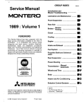
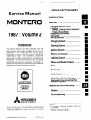
Service Manual
..............................
INTRODUCTION
MONTERO
...........................................
Electrical
1987 : Volume
Electrical System Parts
Location .........................................
Relays, Control Units, Sensors,
Fuses, Groundings
Inspection of Harness
......................................
Connector
.............................
Wiring Harness
2
Charging
FOREWORD
This Service Manual has been prepared with the
latest service information
available at the time of
publication.
It is subdivided
into various group
categories
and each section contains
diagnosis,
procedures
disassembly,
repair, and installation
along with complete
specifications
and tightening
references.
Use of this manual will aid in properly
performing
any servicing necessary to maintain
or
restore the high levels of performance
and reliability
designed into these outstanding
vehicles.
..........................
System
Starting
System
............................
Ignition
System
.............................
Meters and Gauges
Lighting
......................
.............................
System
Wiper and Washer System
Horn
..........
...............................................
Accessory
......................................
Audio System
................................
Back Door Window Defogger ......
Automatic
Free-wheeling
Hub
..........................
Indicator System
WE SUPPORT
VOLUNTARY
TECHNICIAN
CERTIFICATION
THROUGH
Heaters and Air-conditioning
Heaters
.........
..........................................
Air-conditioning
............................
MITSUBISHI
MOTOR SALES
OF AMERICA.
Inc.
Mitsubishi
Motors
corporation
reserves
the right to make changes
in
design or to make additions
to or improvements
in its products without
imposing
any obligations
upon itself to install them on its products
previously
manufactured.
0 1986 Mitsubishi
Motors
Corporation
Printed
in Japan
For Engine
**,
Chassis
& Body
refer
to
2
INTRODUCTION
- How To Use This Manual
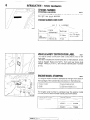
HOW TO USE THIS MANUAL
NOOBAAK
CONTENTS
The preceding
page contains
the GROUP
which lists the group title and group number.
INDEX
PAGE NUMBERS
All page numbers
consist of two sets of digits
separated by a dash. The digits preceding the dash
identify the number of the group. The digits following the dash represent
the consecutive
page
number within the group.
The page numbers can
be found on the top left or right of each page.
piiiKL=lIndicates
TEXT
Unless otherwise specified, each service procedure
covers all models.
Procedures
covering specific
models are identified by the model codes, or similar
designation
(engine type, transmission
type, etc.).
A description
of these designations
is covered in
this unit under “VEHICLE IDENTIFICATION”.
SERVICE
incidental
Removal steps : The numbers before part names
correspond
to numbers in the illustration and indicate the order of
removal.
Disassembly steps : The numbers
before
part
names correspond to numbers
in the illustration, and indicate
the order of disassembly.
PROCEDURES
The service steps are arranged in numerical
order
and attentions
to be paid in performing
vehicle service are described in detail in SERVICE POINTS.
Installation steps This is provided
DEFINITION
Reassembly
OF TERMS
STANDARD
VALUE
Indicates the value used as the standard for judging
the quality of a part or assembly on inspection
or the
value to which the part or assembly is corrected and
adjusted.
It is given by tolerance.
operation
if installation
cannot be made in the reverse
order of “Removal steps”; omitted if installation in the reverse
order of “Removal
steps” is
possible.
.
steps : I his IS provided It reassembly
cannot be made in the reverse
order of “Disassembly
steps”;
omitted if reassembly
in the
reverse order of “Disassembly
steps” is possible.
\
LIMIT
Shows the standard for judging the quality of a part
or assembly on inspection and means the maximum
or minimum
value within which the part or assembly
must be kept functionally
or in strength.
It is a value
established
outside the range of standard value.
Classification of
SERVICE ROINTS
Oe : Removal
**
: Installation
Oe : Disassembly
I)+ : Reassembly
Page number
3
- How To Use This Manual
INTRODUCTION
Group title
Section title
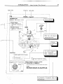
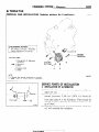
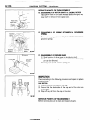
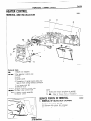
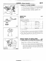
THERMOSTAT
REMOVAL
AND
INSTALLATION
1 torque
I
I
I
-L
0480031
Thermostat
kit
Repair
kit or set
parts
are
I
!
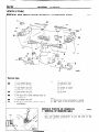
Removal
+
I s
B~C
1. Connectw
of water
temperature
switch
connector
(Vehicles
with an air condltloneri
2 Connection
of radiator
upper
hose
3 Water
outlet
fitting
4 Water
outlet
fitting
gasket
5. Thermostat
This number corresponds
to
the number
in “Removal
steps”, ” Disassembly
steps”, “Installation
steps”
or “Reassembly steps”.
NOTE
(1) Reverse the removal procedures
to reinstall
12) l * : Refer to “Sewce
Points of Installation”
Nowreusable
parts
(3) q
-r
L
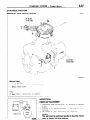
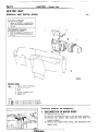
SERVICE
45.
POINTS
OF lNSTALLATlON--
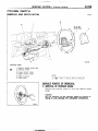
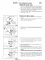
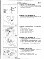
INSTALLATION
Install
the
OF
thermostat
Caution
The
thermostat
ensure
that
the
THERMOSTAT
to the
flange
thermostat
fits
Intake
over
is not
manifold
as illustrated.
the
manifold
installed
at an
seat;
angle.
An explanation
of procedures,
notes, etc.
regarding removal installation
disassembly
(and reassembly.
’
’
-1
INTRODUCTION
-
Vehicle
Identification
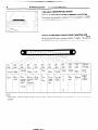
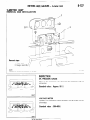
VEHlCLE IDENTIFICATION
“&LE
IDENTIFICATION
NUMBER
LOCATIOyo(lcAmm
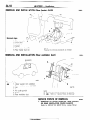
The vehicle identification
number (V.I.N.) is located
attached to the left top side of the instrument
panel.
VEHICLE
lDENTlFlCATlON
All vehicle identification
number is a code which
\
6th
digit
!
Country
Make
JJapan
AMitsubishi
Vehicle
type
4-
Multipurpose
vehicle
(MPW
CODE CHART PLATEo,,.,
numbers
contain 17 digits.
tells country, make, vehicle
7th
digit
8th
digit
9th
digit
10th
digit
Price
class
Body
Engine
Check
digit
Model
year
JF4001 Ibs. MON-
2-
3-
Low
or more TERO
with
hydraulic
brakes
4-
3-door
metaltop or
van
E2.6 liters
(155.9
C.I.D.)
Line
High
0
1
2
3
on a plate
Plant
The vehicle
type, etc.
1 ZZ-Zer
1
H1987
year
7-Truck
9
X
NOTE
*“Check digit” means a single number or letter X used to verify the accuracy of transcription of vehicle indentification
number.
1 STB Revision
1
I
:
“’
INTRODUCTION
VEHICLE
IDENTIFICATION
NUMBER
5
- Vehicle Identification
LIST
FEDERAL
NOOCC-
VIN (except sequence
number)
Model code
Engine displacement
Brand
L042GVNJLF
L042GVRJLF
JA4FJ43EoHJ
JA4FJ43EoHJ
MITSUBISHI
JA7FJ23EoHJ
MONTERO
2.555 liters
(155.9 C.I.D.)
L042GTNSLF
L042GTRSLF
JA7FJ23EoHJ
CALIFORNIA
(Can also be sold in Federal
VIN (except sequence
number)
states.)
Model code
Engine displacement
Brand
L042GVNJLH
JA4FJ43EoHJ
JA4FJ43EoHJ
JA7FJ23EoHJ
MITSUBISHI
MONTERO
2.555 liters
L042GVRJLH
(155.9 C.I.D.)
L042GTNSLH
1 L042GTNSLH
JB7FJ23EoHJ
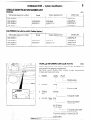
VEHICLE
INFORMATION
CODE PLATE
Vehicle information
code plate is riveted
port panel in the engine compartment.
The plate shows
model code, engine
model, and body color code.
1.
MODEL
L042G
2.
ENGINE
G54B
on the headlight
model,
Engine
COLOR,
transmission
model
KM145
TRANS
AXLE
Transaxle
4.
sup-
VNJLF
I
3.
NOOCO-A
TRIM
OPT
model
876
Montone
exterior
color code
OOK520
B2 1 B76H43
Two-tone
color code
Exterior code
Two-tone
exterior is shown
by the
exterior code followed
by the two
color codes.
F
._:
) STB Revision
6
INTRODUCTION
- Vehicle
Identification
CHASSIS
NUMBER
STAMPING
LOCATION
NOOCE-A
The chassis
number is stamped
the right rear shock absorber.
CHASSIS
NUMBER
A’
i’
on the side of the frame
near
CODE CHART
LO4
2
V
HJOOOOOl
,
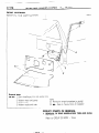
VEHICLE
SAFETY CERTIFICATION
LABEL
NOOCF-
The vehicle safety certification
label is attached
to face of left
door pillar.
This label indicates
the month and year of manufacture,
Gross
Vehicle Weight
Rating (G.V.W.R.),
front and rear Gross Axle
Weight
Rating (G.A.W.R.),
and Vehicle Identification
Number
(V.I.N.).
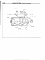
ENGINE
MODEL STAMPING
NOOCG-
The engine model number is stamped
at the right front side on
the top edge of the cylinder block as shown
in the following:
1 Engine model
1 Engine displacement
1 2.555 liters (155.9 C.I.D.)
The engine serial number
is stamped
number, and the serial number cycles,
Engine serial number
Number
near the engine
as shown
below
model
cycling
AA020’toYY=
/ STB Revision
--I
j ‘. f
.,,.
..-.
INTRODUCTION
- Vehicle
7
Identification
BODY COLOR CODE
NOOCH-
Body color
Exterior code
Monotone
B76
Dark blue (Metallic)
Cl9
Brown
H43
Silver (Metallic)
R52
Red
s70
x15
Beige
(Metallic)
Black
Two-tone
1 STB Revision
B21 B76H43
Silver (Metallic)/
Dark blue (Metallic)
C38C19X13
Black/
Brown (Metallic)
H15H43X13
Black/
Silver (Metallic)
R06R52X13
Black/Red
S69S7OX13
Black/Beige
X45X1 5H43
Black/
Silver (Metallic)
8
INTRODUCTION
- Precautions Before Service
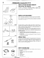
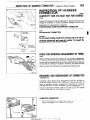
PRECAUTIONS
PROTECTIN”
BEFORE SERVICE
THE VEHICLE
NOODAAC
If theIre is a likelihood
of damaging
painted or interior parts
during service operations,
protect them with suitable covers
(such as seat covers. fender covers, etc.).
REMOVAL
AND DISASSEMBLY
When checking a malfunction,
find the cause of the problem.
If it is determined
that removal and/or disassembly
is necessary, perform the work by following the procedures
contained
in this, Workshop
Manual.
oorn,
FOOOl;
If punch marks or mating marks are made to avoid error in
assembly
and facilitate the assembly
work, be sure to make
them in locations
which will have no detrimental
effect on
performance
and/or appearances.
If an area having many parts, similar parts, and/or parts which
are’ symmetrical
right and left is disassembled,
be sure to
arrange the parts so that they do not become mixed during the
assembly process.
1. Arrange the parts removed in the proper order.
2. Determine
which parts are to be reused and which are to
be replaced.
3. If bolts, nuts, etc., are to be replaced, be sure to use only
the exact size specified.,
SPECIAL TOOLS
If other tools are substituted
for the special tools to do service
or repair work, there is the danger that vehicle parts might be
damaged,
or the mechanic
might be injured;
therefore,
be
sure to use the special tool whenever
doing any work for
which the use of one is specified.
FOOOl8
r
PARTS TO IBE REPLACED
DO05111
If any of the following
parts are removed,
replaced with new parts.
1. Oil seals
2. Gaskets (except rocker cover gasket)
3. Packings
4. O-rings
5. Lock washers
6. Cotter pins
7. Self-locking
nuts
STB Revision
they
,j
.’
must
be
INTRODUCTION
- Precautions
9
Before Service
PARTS
When
replacing
VEHICLE
parts,
use MITSUBISHI
genuine
parts.
WVASHING
If high-pressure
car-washing
equipment
or steam car-washing
equipment
is used to wash the vehicle, be sure to maintain the
spray nozzle at a distance
of at least 300 mm (1 1.8 in.) from
any plastic
parts
and all opening
parts
(doors,
luggage
compartment,
etc.).
nm
(in.)
so0059
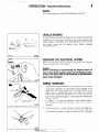
SERVICING
THE ELECTRICAL
When
cable
the electrical
system,
from the battery.
servicing
terminal
SYSTEM
disconnect
the negative
Caution
Before connecting
or disconnecting
the negative
cable, be
sure to turn off the ignition
switch
and the lighting
switch.
(If this is not done, there is the possibility
of semiconductor
parts
being damaged.)
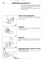
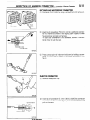
WIRING
1.
Secure the wiring
harnesses
by using clamps so that there
is no slack. However,
for any harness which passes to the
engine or other vibrating
parts of the vehicle, allow some
slack within
a range that does
not allow
the engine
vibrations
to cause the harness
to come into contact with
any of the surrounding
parts. Then secure the harness
by
using a clamp.
In addition,
if a mounting
indication
mark (yellow
tape) is
on a harness,
secure the indication
mark in the specified
location.
2.
If any section
of a wiring
harness
contacts
the edge of a
part, or a corner, wrap the section of the harness with tape
or something
similar in order to protect
it from damage.
F161711
*
:,
:,
HARNESSES
1 STB Revision
INTRODUCTION
- Precautions
Before
Service
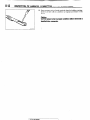
3. When disconnecting
a connector,
connector, not the harness.
be sure to pull only the
4.
Disconnect
connectors
the direction indicated
which have catches by pressing
by the arrows in the illustration.
5.
Connect connectors
which have catches
connectors
until they snap.
in
16Rl263
16R1264
Y16347
by inserting
( STB Revision
‘.
the
INTRODUCTION
- Precautions
Before
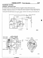
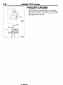
ELECTRICAL COMPONENTS
1. When installing any of the vehicle
pinch or damage
2.
3.
I
11
Service
any of the wiring
Sensors,
relays, etc., are sensitive
Handle them with care so that
mishandled.
parts, be careful
harnesses.
not to
to strong impacts.
they are not dropped
or
The electronic
parts used for relays, etc., are sensitive
to
heat, If any service
which causes
a temperature
of 80°C
(176°F) or more is performed,
remove the part or parts in
question
before carrying out the service.
OOY63:
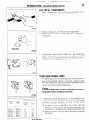
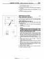
FUSES AND FUSIBLE
1.
LINKS
If a blown-out
fuse is to be replaced,
be sure to use only a
fuse of the specified
capacity.
If a fuse of a capacity
larger
than that specified
is used, parts may be damaged
and the
circuit may not be protected
adequately.
Caution
If a fuse is blown-out,
be sure to eliminate
the problem
before installing
a new fuse.
15A
IOA
the cause
of
oOY58S
1
Permissible
current
1
2
Nominal
size
0.3 mm2
05mm’
0.85 mm2
1.25 mm2
2.0 mm2
AWG22
AWG 20
AWG18
AWG 16
AWG14
~
I
5A
13A
17A
22A
30A
zi
12A
16A
I
Revision
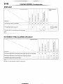
If additional
optional
equipment
is to be installed
in the
vehicle,
follow
the procedure
listed in the appropriate
instruction
manual;
however,
be sure to pay careful
attention to the following
points:
(1) In order
to avoid overloading
the wiring,
take the
electrical
current
load of the optional equipment
into
consideration,
and determine
the appropriate
wire size.
(2) Where
possible,
route the wiring through
the existing
harnesses.
12
INTRODUCTION
- Precautions
Before
Service
(3) If an ammeter
or similar instrument
is to be connected
to a live-wire
circuit, use tape to protect the wire, use a
clamp to secure the wire, and make sure that there is
,i no contact with any other parts.
(4’) Be sure to provide a fuse for the load circuit of the
optional equipment.
TUBES AND OTHER RUBBER PARTS
Be careful to avoid spilling any gasoline,
adheres
to any tubes or other rubber
adversely
affected.
oil, etc.. because
parts, they might
if it
be
LUBRICANTS
In accordance
with the instructions
in this Workshop
Manual,
apply the specified
lubricants
in the specified
locations
during
assembly
and installation.
FooO281
BRAKE FLUID
Be careful
to avoid spilling
adheres
to the vehicle body,
ored.
DOING SERVICE WORK
MORE TECHNICIANS
If the service
extra caution
any brake fluid, because
if it
the paint coat might be discol-
IN GROUPS
work is to be done
must be taken.
by two
OF TWO OR
or more
-FOOO3OI
1 STB Revision
’
:
technicians
INTRODUCTION
- Precautions
IKITE
13
Before Service
ON INSTALLATION
OF RADIO
EQUIPMW&
The computers
of the electronic
control
system
has been
designed
so that external
radio waves
will not interfere
with
their operation.
However,
if antenna
or cable of amateur
transceiver
etc. is
routed near the computers,
it may affect the operation
of the
computers,
even if the output of the transceiver
is no more
than 25W.
To protect
each of the computers
from
interference
by
transmitter
(hum, transceiver,
etc.), the following
should be
observed.
1. Install the antenna
on the roof.
2. Because radio waves are emitted from the coaxial cable of
the antenna,
keep
it 200 mm (8 in.) away
from
the
computers
and the wiring harness.
If the cable must cross
the wiring harness,
route it so that it runs at right angles to
the wiring
harness.
3. The antenna
and the cable should be well matched,
and
the standing-wave
ratio* should
be kept low.
4. A transmitter
having a large output should not be installed
in the vehicle.
5. After installation
of transmitter,
run the engine at idle, emit
radio waves
from the transmitter
and make sure that the
engine is not affected.
High-frequency
power supply
_.
If an antenna
and a cable having different
impedances
are
connected,
the input impedance
Zi will vary in accordance
with
the length
of the cable and the frequency
of the
transmitter,
and the voltage
distribution
will also vary in
accordance
with the location.
The ratio between
this maximum
voltage
and minimum
voltage
is called the standing-wave
ratio. It can also be
represented
by the ratio between
the impedances
of the
antenna and the cable.
The amount of radio waves
emitted from the cable increases
as the standing-wave
ratio increases,
and this increases
the
possibility
of the electronic
components
being
adversely
affected.
r.
;
ST6 Revision
INTRODUCTION
- Towing
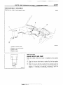
TOWING
and Hoisting
AND HOISTING
NOOGA-
This vehicle can only be towed from the front with conventional sling-type
equipment
and tow chain with grab hooks.
If a vehicle is towed from the rear, use a tow dolly.
A lumber spacer (4” x 4” x 55” wood beam) should be placed
forward
of under guard and under towing
hook/shipping
tie
down hook.
Then, attach J-hook to the lower arm.
A safety chain system
must be used. This system
must be
completely
independent
of the primary
lifting and towing
attachment.
Care must be taken in the installation
of safety
chains to insure they do not cause damage to bumper,
painted
surfaces
or lights.
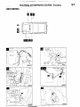
LIFT!NG-GROUND
CLEARANCE
Towed vehicle should be raised until wheels
are a minimum
of
10 cm (4 in.) from the ground.
Be sure there is adequate
ground clearance
at the opposite
end of the vehicle, especially
when towing
over rough terrain or when crossing
sharp rises
such as curbs.
If necessary,
ground
clearance
can be increased
by removing
the wheels
from the lifted end of the
disabled
vehicle
and carrying
the lifted end closer
to the
ground. A 20 cm (8 in.) ground clearance
must be maintained
between
brake drums and ground.
FRONT TOWING
PICKUP
The vehicle may be towed
on its rear wheels
for extended
distances,
provided the parking brake is released.
Make cartain the transmission
remains in “NEUTRAL”.
SAFETY PRECAUTIONS
The following
precautions
should be taken when towing
the
vehicle.
1. Remove
exhaust
tips and any other optional
equipment,
that interface
with the towing
sling. Padding (heavy shop
towel or carpeting)
should be placed between
the towing
sling cross
bar and any painted
surfaces,
and bumper
surfaces.
2. A safety
chain system
completely
independent
of the
primary lifting and towing
attachment
must be used.
3. Any loose or protruding
parts of damaged
vehicle such as
hoods, doors, fenders,
trim, etc., should be secured
prior
to moving the vehicle.
4. Operator
should refrain from going under a vehicle unless
the vehicle is adequately
supported
by safety stands.
5. Never allow passengers
to ride in a towed vehicle.
6. State and local rules and regulations
must be followed
when towing
a vehicle.
‘
1 STB Revision
INTRODUCTION
- Towing
and
15
Hoisting
HOISTING
POST TYPE
Special care should
be taken when raising the vehicle on a
frame contact type hoist. The hoist must be equipped
with the
proper adapters
in order to support
the vehicle at the proper
locations.
(See next page)
Conventional
hydraulic
hoists may be used after determining
that the adapter
plates will make firm contact
with the side
frame.
FLOOR
JACK
A regular floor jack may be used
or rear axle housing.
under the front
crossmember
Caution
1. A floor jack must
never
be used on any part of the
underbody.
2. Do not attempt
to raise one entire side of the vehicle by
placing a jack midway
between
front and rear wheels.
This practice
may result
in permanent
damage
to the
body.
EMERGENCY
JACKING
Jack receptacles
are located at the No. 2 crossmember
and
rear axle housing
to accept the jack supplied
with the vehicle
for emergency
road service. Always
block the opposite
wheels
and jack only on a level surface.
.::
. Y!’.I,,.
‘.
I
1 STB Revision
16
FRAME
INTRODUCTION
CONTACT
SUPPORT
support
of the
below.
and
Hoisting
LOCATIONS
2,350
NOTE
The locations
of the
the
same
as those
illustration
(OOW588)
Towitng
-
point
twin
shown
as Section
post
hoist
shown
A-A
in
mm
(92.5
in.)
Section
A-A
are
the
oow553
LIFTING
AND JACKING
c
m
@B
SUPPORT
Twin
post
Floor
lack
Emergency
LOCATIONS
hoist
jacking
(jack
supplied
with
the
vehicle)
OOW588
INTRODUCTION
GENERAL
- Geraeral
17
Data and Specifications
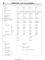
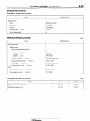
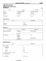
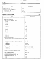
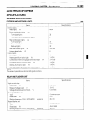
DATA AND SPECIFICATIONS
NOOHA-A
OOW556
L042G
Description
Vehicle dimensions
VNJ LFIH
VRJLFIH
TRSLF/H
TNSLFIH
mm (in.)
Overall length
Without spare tire
0
3,960 (155.9)
3,960 (155.9)
3,960 (155.9)
3,960 (155.9)
With spare tire
Overall width
0
0
3,995 (157.3)
1,680 (66.1)
3,995 (157.3)
1,680 (66.1)
3,995 (157.3)
1,680 (66.1)
3,995 (157.3)
1,680 (66.1)
Overall height
0
1,840 (72.4)
1,840 (72.4)
1,850 (72.8)
1,850 (72.8)
Wheelbase
0
2,350 (92.5)
2,350 (92.5)
2,350 (92.5)
2,350 (92.5)
Front
@
1,400 (55.1)
1,400 (55.1)
1,400 (55.1)
1,400 (55.1)
Rear
0
1,375 (54.1)
1,375 (54.1)
1,375 (54.1)
1,375 (54.1)
Tread
Overhang
Front
@
745 (29.3)
745 (29.3)
745 (29.3)
745 (29.3)
Rear
@
900 (35.4)
900 (35.4)
900 (35.4)
900 (35.4)
@
480 (18.9)
480 (18.9)
480(18.9)
440(17.3)
480 (18.9)
440(17.3)
210 (8.3)
210 (8.3)
Height at curb weight
(wt.)
Front bumper to ground
Rear bumper to ground
Minimum running ground
clearance
Angle of approach
Angle of departure
:
440(17.3)
210 (8.3)
440(17.3)
210 (8.3)
@
@
38
28
38
28”
38”
28
38
28
Ramp breakover
@
21”
21”
21”
21”
1,479 (3,260)
1,493 (3,290)
1,440 (3,175)
1,460 (3,219)
I,91 0 (4.210)
Vehicle weights
Curb weight
angle
kg (Ibs.)
Gross vehicle weight
Gross axle
rating
Front
1,910 (4,210)
1 ,I 00 (2,425)
I,91 0 (4,210)
1 ,I 00 (2,425)
1,910(4,210)
1 ,I 00 (2,425)
weight ratin!g~:+y~
Seating,c&ac&~
.’
:I’ ;.,* .’ ..,,
VU.,
,: ‘,_.: .,
”
,_;. ,; ,: 3,‘. r
Rear
1,450 (3,197)
4
1,450 (3,197)
4
1,450 (3,197)
2
STB Revision
1,100 (2,425)
1,450 (3,197)
2
18
INTRODUCTION
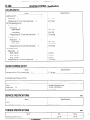
L042G
Description
- General
Data and Specifications
VNJLFIH
TNSLFIH
VRJ L.F/H
TRSLFIH
1
Engine
Model
G54B
No.
Type
Number
i In-line
‘4
of cylinders
G54B
G54B
OHC
In-line
4
G54B
In-line
OHC
OHC
4
In-line
OHC
4
Bore
91 .I mm (3.59 in.) 91 .I mm (3.59 in.) 91 ,I mm (3.59 in.) 91 .I mm (3.59 in.)
Stroke
98.0 mm (3.86 in.) 98.0 mm (3.86 in.) 98.0 mm (3.86 in.) 98.0 mm (3.86 in.)
Piston
displacement
Compression
ratio
Firing
order
Basic
ignitron
Transmission
Model
trming
&transfer
2,555 cm”
(155.9 CID)
8.7
2,555 cm”
(155.9 CID)
2,555 cm3
(155.9 CID)
2,555 cm3
(155.9 CID)
8.7
8.7
8.7
I-3-4-2
I-3-4-2
1-3-4-2
1-3-4-2
7” BTDC
? 2”
7” BTDC
? 2”
7” BTDC
2 2”
‘7” BTDC
case
No.
KM145
KM148
KM145
KM148
5-speed
manual
4-speed
automatic
5-speed
manual
4-speed
automatic
1 st
3.967
2.826
3.967
2.826
2nd
2.136
1.493
2.136
1.493
3rd
1.360
1 .ooo
1.360
1.000
4th
5th
1.000
0.856
0.688
-
1 .ooo
0.856
0.688
-
Reverse
3.578
2.703
3.578
2.703
High
1.000
1.000
1.000
1 ,040
Low
1.944
1.944
1.944
1.944
4.625
4.625
4.625
4.625
Dry single
-
Dry single
-
Type
Cear ratio
Transmjssion
Transfer
case
Final ring gear ratio
Zlutch
Type
disc &
disc &
diaphragm
diaphragm
spring
spring
Chassis
Tire size
Front suspension
P225/75R15
Type
Spring
constant
Wishbone
compression
(Wheel
position)
22 N/mm
(123 Ibs./in.)
type
Rear suspension
Type
Spring
Asymmetrical
semi-elliptic
leaf spring
constant
At load of 1 ,OOO-2,500
(220-551
Ibs.)
N
22 N/mm
(123 Ibs./in.)
At load of 4,670-8,870
(1,030-I
,955 tbs.)
N
50 N/mm
(280 Ibs./in.)
1 STB Revision
..,j ;
* :
:
? 2”
INTRODUCTION
Description
m--__
L042G
Data and
General
Specifications
VRJLFIH
VNJLFIH
/ Tightening
Torque
TNSLFIH
19
TRSLFIH
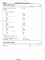
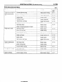
Brakes
We
Power
Front
Disc
Rear
Drum
(Leading
steering
Gear type
Integral
Gear ratio
ball nut)
60 liters (15.9 U.S. gal./1 3.2 Imp. gal.)
TIGHTENING
TORQUE
NOOJA-
Description
Head mark
Head mark
Nm
Thread for general
(size x pitch) mm
07
ft.lbs.
ft.lbs.
Nm
2.2-2.9
4.9-7.8
3.6-5.8
purposes
I
6x 1.0
3.0-3.9
8x 1.25
7.9-I
5.8-8.7
13-19
9.4-14
10x 1.25
16-23
12-17
27-39
20-29
12 x 1.25
29-43
21-32
47-72
35-53
14x 1.5
48-70
35-52
77-l
16x 1.5
677100
18x1.5
100-l
50
74-I
20x
150-I
90
1.5
2
51-77
90-I
160-320
1 go-240
340-430
250-320
420-550
310-410
260-320
1 go-240
Nm
ft.lbs.
90
Remarks
(size)
PT l/8
Internal
Internal
thread:
thread:
Aluminum
Cast iron
PT l/4
Internal
Internal
thread:
thread:
Aluminum
Cast iron
PT 318
Internal
Internal
thread:
thread:
Aluminum
Cast iron
thread
for dry sealed
pipes (size)
NPTF l/16
4.9-7.8
7.9-I 2
3.6-5.8
5.8-8.7
Internal
Internal
thread:
thread:
Aluminum
Cast iron
NPTF l/8
7.9-I 2
16-19
5.8-8.7
12-14
Internal
Internal
thread:
thread:
Aluminum
Cast iron
NPTF l/4
19-13
34-45
14-22
25-33
Internal
Internal
thread:
thread:
Aluminum
Cast iron
.
) STB Revision
20
1 IO-140
24x
for pipes
60
130-170
150-I
thread
57-85
180-230
200-260
1.5
10
130-I
10
22 x 1.5
Description
Tape
type (Recirculating
16.4
Fuel tank capacity
Taper
and trailing)
8-1
ELECTRICAL
CONTENTS
ACCESSORY
......................................................
188
Cigarette Lighter
............................................
,190
Clock ...............................................................
,191
AUDIO SYSTEM
................................................
.192
AUTOMATIC
FREE-WHEELING
HUB
INDICATOR
SYSTEM
........................................
208
Automatic
Free-wheeling
Hub
Indicator Control Unit .....................................
,216
Pulse Generator
..............................................
215
BACK DOOR WINDOW
DEFOGGER
................ .203
Defogger switch
............................................
,206
Printed Heater Lines ......................................
,207
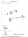
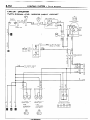
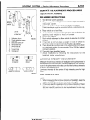
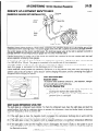
CHARGING
SYSTEM
.........................................
71
Alternator
........................................................
83
Service Adjustment
Procedures
.....................
77
Battery Charging
........................................
82
Inspection
of Battery ..................................
81
Output Current Test ...................................
78
Regulated Voltage Test ..............................
79
Voltage Drop Test of Alternator Output
Wire ............................................................
77
ELECTRICAL
SYSTEM PARTS LOCATION
...... 2
Diode ...............................................................
5
Fusible Link and Fuse .....................................
6
.......................................................
Grounding
7
Relay and Control Unit ....................................
2
Sensor .............................................................
4
HORN ..................................................................
184
Horn Switch
....................................................
187
IGNITION
SYSTEM
............................................
105
Ignition Switch ................................................
122
Ignition System
...............................................
1 14
Service Adjustment
Procedures
.................... .l 1 1
Checking Ignition System
..........................
11 1
Checking Ignition Timing
...........................
11 1
Spark Plug Cable Test ................................
1 12
Spark Plug Test ..........................................
1 12
NOBAA-
......
9
INSPECTION
OF HARNESS CONNECTOR
Check for Improper Engagement
of
..........................................................
9
Terminal
Continuity and Voltage Test for Connector
.... 9
Engaging and Disengaging
of Connector
Terminal
..........................................................
9
143
LIGHTING
SYSTEM
...........................................
Column Switch ................................
. .............. .I59
Dimmer Control Switch .................................
.I62
Hazard Warning Switch .................................
.I61
Headlight
........................................................
,158
Service Adjustment
Procedures
.................... .I57
Headlight Aiming
.......................................
157
METERS AND GAUGES
....................................
123
Service Adjustment
Procedures
.................... .I30
Fuel Gauge Simple Test .................................
.I31
Fuel Gauge Unit Inspection
...........................
.I31
Oil Pressure Gauge Simple Test .................... .I32
Oil Pressure Gauge Unit Simple Test ............ ,132
Speedometer
Inspection
.I30
...............................
Tachometer
Inspection
..................................
,130
Voltage Meter Simple Test ............................
.I33
Water Temperature
Gauge Simple Test ....... ..I3 1
Water Temperature
Gauge Unit Inspection
. ..I3 2
..........................................
91
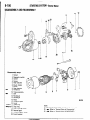
STARTING
SYSTEM
97
Starter Motor ............ .......................................
WIPER AND WASHER SYSTEM
.163
.......................
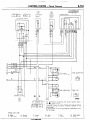
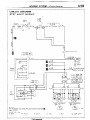
WIRING
HARNESS
............................................
13
Centralized Junction
.......................................
69
Circuit Diagram
...............................................
34
27
Configuration
Diagram
....................................
How to Read Wiring Diagrams
.......................
20
Troubleshooting
..............................................
13
8-2
ELECTRICAL
ELECTRICAL
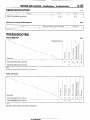
SYSTEM PARTS LOCATION
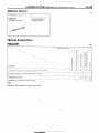
SYSTEM
- Relay
and Control
Unit
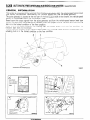
IPARTS LOCATION
NOIBAB-A
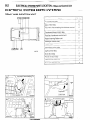
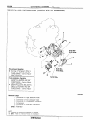
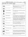
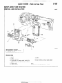
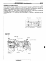
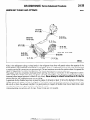
RELAY AND CONTROL UNIT
Items
--
Symbol
D
Air conditioner
relay
-Auto choke relay
-Automatic
free-wheeling
G
hub indicator control
A
unit
16W722
A
n 17
A
Condenser blower motor relay
H
Feed back carburetor control unit
C
Hazard warning flasher unit
F
Headlight washer relay
F
Heater relay
E
Intermittent wiper relay
~___
Light control relay
~___
Over drive relay
F
I
F
Power window relay
F
Seat belt warning timer
B
Turn-signal flasher unit
F
Automatic free-wheeling
2
\ hub indicator control unit
carburetor
control unit
Air conditioner
d---
Blower
assembiy&
x
v/i
16W152B
1.STB Re\iision
Jr
relay
I-
EvaporatorE
ELECTRICAL
FI)I
-Headlight h”
k\\\
washer
SYSTEM
PARTS LOCATION
relay
Hazard warnina
f
1 STB Revision
- Relay and Control Unit
8-3
8-4
ELECTRICAL
SYSTEM PARTS LOCATION
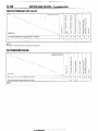
- Sensor
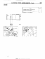
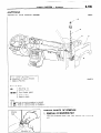
SENSOR
Symbol
Items
A
Oxygen
sensor
Pulse generator
B
--
D
Throttle position sensor
_____
Vehicle-speed
sensor
C
~~
Water
temperature
E
sensor
ltw722
I
Ileedometer
16W1506
p
Revision
Throttle
position
sensor.
I
ELECTRICAL
SYSTEM
PARTS LOCATION
8-5
- Diode
DIODE
Diode (for automatic
transmission
Diode (for EGR warning
1 @NJ22
STB Revision
light)
oil
ELECTRICAL
SYSTEM
PARTS LOCATION
- Fusible Link and Fuse
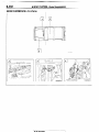
FUSIBLE LINK AND FUSE
-Items
Symbol
Dedicated
fuse (for air conditioner
Dedicated
fuse (for headlight
circuit)
1
/ STBI
levision
‘I E
A
Multipurpose
C
fuse
NOTE
For detailed information
concerning
fuses, refer to the section regarding
TION (P.8-69, 70.)
-Evaoorator
B
Main fusible link
Sub fusible link
16W722
circuit)
D
the fusible links and
CENTRALIZED
JUNC-
ELECTRICAL
SYSTEM PARTS LOCATION
8-7
-Grounding
GROUNDING
Headlight
washer relay,
h
I
1 STB Revision
!Ja
_ .-----
-/
/
8-8
ELECTRICAL
\\/
/
16W1512
SYSTEM
PARTS LOCATION
-Grounding
1
5.
STB Revision
1
:.,
i
INSPECTION
OF HARNESS
CONNECTOR
-
Inspection
of Harness
8-9
Connector
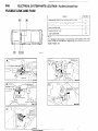
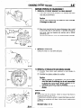
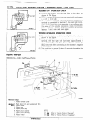
INSPECTION OF HARNESS
CONNECTOR
CONTINUITY
TOR
AND VOLTAGE
NOECAM
TEST FOR CONNEC-
Following procedures shall be followed for testing continuity and
voltage at connector in order to prevent improper contact and
deterioration of waterproof in connector.
CONVENTIONAL
(NON-WATERPROOF)
CONNECTOR
Check shall be done by inserting a probing needle from harness
side.
WATER PROOF CONNECTOR
Caution.
Do not insert probing needle from harness side as it will deteriorates
waterproof
and cause for rusting. To inspect the
energized circuit, use the ECI checker.
Connect
harness
to
16UO500
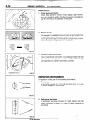
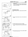
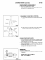
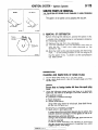
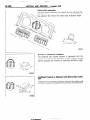
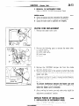
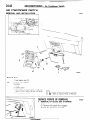
CHECK FOR IMPROPER
NAL
ENGAGEMENT
OF TERMI-
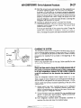
When terminal stopper of connector is out of order, engagement
of male and female terminals becomes improper even when connector itself is engaged perfectly and terminal sometimes
slips out
to rear side of connector. Ascertain, therefore, that each terminal
does not come off connector by pulling each harness wire.
16R1317
ENGAGING
TERMINAL
AND DISENGAGING
OF CONNECTOR
Connector which gives loose engagement
shall be rectified by
removing female terminal from connector housing and raise its
lance to establish securer engagement.
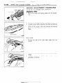
Removal of connector
housing and raise its lance to establish securer engagement.
Removal of connector terminal used for ECI and ELC 4 ,4/l control
circuit shall be done in the following manner.
COMPUTER
CONNECTOR
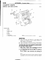
(1) Insert screwdriver [1.4 mm (06 in.) width] as shown
figure, disengage front holder and remove it.
8;
:
4
.j ’ _.
16R1319
1 STB Revision
in the
8-10
INSPECTION
OF HARNESS
CONNECTOR
-
Inspection
of Harness
Connector
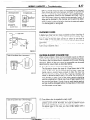
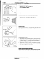
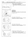
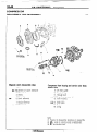
(2) Insert harness of terminal to be rectified deep into connector
from harness side and hold it there.
(3) Insert tip of screwdriver [1.4 mm (.06 in.) width] into connector
in a manner as shown in the figure, raise housing lance slightly
with it and pull out harness.
Housing lance
NOTE
Tool No. 753787-l
of screwdriver.
-5
1
supplied
by AMP can be used instead
16R1321
(4) Insert needle through a hole provided on terminal and raise
contact point of male terminal.
’
Needle
16Ffi322
ROUND
WATERPROOF
CONNECTOR
(1) Remove waterproof cap by using a screwdriver.
(2) Insert tip of screwdriver [1.4 mm (.06 in.) or 2.0 mm (.08 in.)
width] into connector in a manner as shown in the figure, raise
housing lance slightly with it and pull out harness.
Housing lance
16R1323
(3) Insert screwdriver through a hole provided on terminal and
raise contact point of male terminal.
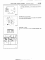
INSPECTION
OF HARNESS
CONNECTOR
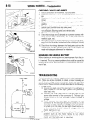
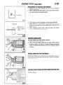
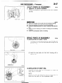
RECTANGULAR
(1) Disengage
-
Inspection
WATERPROOF
front
of Harness
Connector
8-71
CONNECTOR
holder by using a screwdriver
and remove
it.
(2) Insert tip of screwdriver
[*0.8 mm (03 in.) width] into connector in a manner as shown in the figure, push it lightly to raise
housing lancer and pull out harness.
*If right size screwdriver
is not available, convert a conventional driver to suit the size.
Housing
lance
16R13
26
(3) Press contact point of male terminal down by holding a screwdriver [1.4 mm (.06 in.) width] in a manner as shown
in the
figure.
16R1329
INJECTOR
(1) Remove
L
CONNECTOR
waterproof
cap.
16R1326)
Terminal
lance
(2) Insert tip of screwdriver
in a manner as shown
pull out harness.
16Rl330
1 STB Revision
[1.4 mm (06 in.) width] into connector
in the figure, press in terminal lance and
8-12
INSPECTION
OF HARNESS
CONNECTOR
-
Inspection
of Harness
Connector
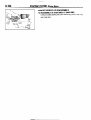
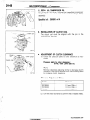
(3) Press contact point of male terminal down by holding a screwdriver Il.4 mm (.06 in.) width] in a manner as shown in the
figure.
Caution
Correct lancer to be in proper
inserted into connector.
I
16R132i
1 STB Revision
condition
before terminal
is
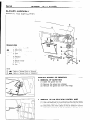
WIRING
HARNESS
8-13
- Troubleshooting
WIRING HARNESS
TROUBLESHOOTING
NO8DAAA
The most important
point in troubleshooting
is to determine
“Probable
Causes”.
Once the probable causes are
determined,
parts to be checked can be limited to those associated
with such probable causes. Therefore,
unnecessary checks can be eliminated.
The determination
of the probable causes must be based on a theory and be
supported
by facts and must not be based on intuition only.
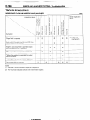
TROUBLESHOOTING
STEPS
If an attempt is made to solve a problem without
going through correct steps
symptoms
could become more complicated,
resulting in failure to determine
incorrect repairs. The four steps below should be followed in troubleshooting.
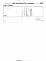
1 1 1 Observation
of Problem
Symptoms
1
Observe
the symptom
problems.
carefully.
for troubleshooting,
the causes correctly
Check
if there
the problem
and making
are also other
b
0,
2
Determination
of Probable
In determining
the probable causes, it is necessary
to check the
wiring diagram to understand
the circuit as a system.
Knowledge
of switches,
relays and other parts is necessary
for accurate determination.
The causes of similar problems
in the past must be
taken into account.
Causes
\
Checking
14
1 Repair
of Parts
and
Confirmation
Associated
Troubleshooting
is carried out by making step by step checks until
the true cause is found. Always go through the procedures
considering what check is to be made where for the best results.
with
1
1 STB Revision
After the problems
are corrected,
be sure to check that the system
operates
that new problems
have not
been
caused
bycorrectly
the
repair, Also check
1
8-14
WIRING
HARNESS
- Troubleshooting
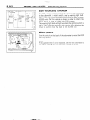
INSPECTION
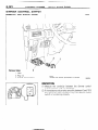
1. Visual and aural checks
Check relay operation, blower motor rotation, light illumination, etc. visually or aurally. The flow of current is invisible but
can be checked by the operation of the parts.
I
2. Simple checks
For example, if a headlight does not come on and a faulty fuse
or poor grounding is suspected, replace the fuse with a new
one or ground the light to the body by a jumper wire to determine which part is responsible for the problem.
1680222
3.
Changeover
knob
Checking with instruments
Use an appropriate instrument
in an adequate range and read
the indication correctly. You must have sufficient knowledge
and experience to handle instruments
correctly.
1680224
INSPECTION
INSTRUMENTS
In inspection, make use of the following
1. Test lamps
instruments.
A test lamp consists of a 12 V bulb and lead wires. It is used
to check voltages or shortcircuits.
1680225
1
2.
Self-power
test lamp
A self-power test lamp consists of a bulb, battery and lead
wires connected in series. It is used to check continuity or
grounding.
,.!‘?i,
1680226
1 STB Revision
,,
6
,‘.’
WIRING
HARNESS
3.
8-15
- Troubleshooting
Jumper wire
A jumper wire is used to close an open circuit. Never use one
to connect a power supply directly to a load.
1660227
4.
A voltmeter is used to measure the circuit voltage. Normally,
the positive (red lead) probe is applied to the point of voltage
measurement and the negative (black lead) probe to the body
ground.
Black lead wire
Ground
Voltmeter
y
1680228
I
5.
Ohmmeter
An ohmmeter is used to.check continuity or measure resistance of a switch or coil. If the measuring range has been
changed, the zero point must be adjusted before measurement.
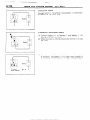
CHECKING
Normal open (NO) type
OFF
SWITCHES
In a circuit diagram, a switch is represented by a symbol and in the
idle state.
ON
1. Normal open or normal close switch
Switches are classified into those which make the circuit open
and those which make the circuit closed when off.
ax
Current does not flow
Current flows
Normal close (NC) type
OFF
ON
-op--
l-2
Current flows
IX
Current does not flow
1680229
pm
#vision
I
8-16
WIRING
HARNESS
- Troubleshooting
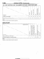
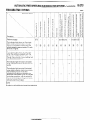
2.
CONNECTION
SWITCH
figure
illustrates
a complex switch. The switch plates
indicated by solid lines move in the direction of the arrow
when operated.
The continuity between terminals at each position is as indicated in the table below.
This
OFF
1st
stage
2nd stage
3rd stage
1
--_
4th stage
1660230
NOTE
M
denotes
continuity
between
terminals.
16W896
CHECKING
Cover
Coil
1. When current flows through the coil of a relay, its core is
magnetized to attract the iron piece, closing (ON) the contact
at the tip of the iron piece. When the coil current is turned off,
the iron piece is made to return to its original position by a
spring, opening the contact (OFF).
Spring
Iron
core
Iron
piece
RELAYS
Contact
1660231
I
2.
Relav
l-
Battery:
-I
d
T
I
T
I
1660232
1
3. The relays may be classified into the normal open type and the
normal close type by their contact construction.
Normal ooen (NO) tvoe
Deenergized
state
Energized
I
ED
1
2
3
4
CurreZ!
not flow
By using a relay, a heavy current can be turned on and off
by a switch of small capacity. For example,
in the circuit
shown here, when the switch is turned on (closed), current
flows to the coil of the relay. Then, its contact is turned on
(closed) and the light comes on. The current flowing at this
time to the switch is the relay coil current only and is very
small.
state
1
BP
NOTE
The deenergized
state means that no kurrent is flowing
through the coil and the energized state means that current is
flowing through the coil.
2
3
4
1 YZZZw;6B0233
J
.
.
.
1 STB Revmon
I
WIRING
Normal
Deenergized
close
state
INC) type
Energized
state
I
Current
-flows
Current
does
HARNESS
8-17
- Troubleshooting
When a normal close type relay as illustrated here is checked,
there should be continuity
between
terminals
(1) and (2) and
between
terminals 3 and 4 when the relay is deenergized,
and the continuity should be lost between
terminals
3 and 4
when the battery voltage is applied to the terminals 1 and 2. A
relay can be checked in this manner and it cannot be determine if a relay is okay or faulty by checking its state only when
it is deenergized
(or energized).
not flow
1680234
CHECKING
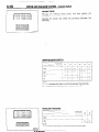
FUSES
A blade type fuse has test taps provided to allow
the fuse itself without
removing
it from the fuse
fuse is okay if the test light comes
on when its
connected
to the test taps (one at a time) and the
grounded.
(Change
the ignition switch
position
adequately
fuse circuit beomes
live.)
checking
of
block. The
one lead is
other lead is
so that the
=
1680235
State
of fuse
blown
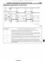
CAUTIONS
due to overcurrent
IN EVENT
OF BLOWN
FUSE
When a fuse is blown, there are two probable causes as follows
: One is that it is blown due to flow of current exceeding its rating.
The other is that it is blown due to repeated on/off current flowing
through it. Which of the two causes is responsible
can be easily
determined
by visual check as described
below.
1660237
I
State
of fuse
blown
due to thermal
fatigue
(1) Fuse blown due to current exceeding rating
The illustration
shows
the state of a fuse blown due to this
cause. In this case, do not replace the fuse with a new one
hastily since a current heavy enough to blow the fuse has
flowed
through
it. First, check the circuit for shorting
and
check for abnormal electric parts. Only after the correction
of
such shorting or parts, fuse of the same capacity should be
used as a replacement.
Never use a fuse of lager capacity than
the one that has blown. If such a fuse is used, electric parts or
wirings could be damaged before the fuse blows in the event
an overcurrent
occurs again.
(2) Fuse blown due to repeated current on/off
The illustration
shows
the state of a fuse blown due to repeated current on/off. Normally, this type of problem occurs
after fairly long period of use and hence is less frequent than
the above type. In this case, you may simply replace with a
new fuse of the same capacity.
WIRING
HARNESS
- Troubleshooting
CHECKING
1660236
CABLES AND WIRES
1. Check connections for looseness, rust and stains.
2. Check terminals and wires for corrosion by battery electrolyte,
$tc.
3. Check terminals and wires for open circuit or impending open
circuit.
4. Check wire insulation and coating for damage, cracks and degrading.
5. Check conductive parts of terminals for contact with other
metallic parts (vehicle body and other parts).
6. Check grounding parts to verify that there is complete continuity between attaching bolt(s) and vehicle body.
7. Check for incorrect wiring.
8. Check that wirings are so clamped as to ‘prevent contact with
sharp corners of the vehicle body, etc. or hot parts (exhaust
manifold, pipe, etc.).
9. Check that wirings are clamped firmly to secure enough clearance from the fan pulley, fan belt and other rotating or moving
parts.
10. Check that the wirings between the fixed parts such as the
vehicle body and the vibrating parts such as the engine are
made with adequate allowance for vibrations.
HANDLING
ON-VEHICLE
BAlTERY
When checking or servicing does not require power from the onvehicle battery, be sure to disconnect the cable from the battery
(-)terminal.
This is to prevent problems that could be caused by
shorting of the circuit. Disconnect the (-) terminal first and reconnect it last.
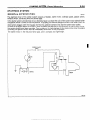
TROUBLESHOOTING
supply
Power
h
/
/
/----
Fuse
ON
Motor
1660239
1 ST6 Revision
A circuit consists of the power supply, switch, relay, load, ground,
etc. There are various methods to check a circuit including an
overall check, voltage check, shortcircuit
check and continuity
check. Each of these methods is briefly described in the following.
1. Voltage check
(1) Ground one lead wire of the test light. If a voltmeter
is
used instead of the test light, ground the grounding
side lead wire.
(2) Connect the other lead wire of the test light to the
power side terminal
of the connector 0. The test light
should come on or the voltmeter
should indicate
a
voltage.
(3) Then, connect
the test light or voltmeter
to the
connector (3,. The test light should not come on, or the
voltmeter
should indicate no voltage. When the switch
is turned on in this state, the test light should come on,
or the voltmeter
should indicate
a voltage,
with the
motor starting to run.
(4) The circuit illustrated
here is normal but if there is any
problem
such as the motor
failing to run, check
voltages
beginning
at the connector
nearest to the
motor unit the faulty part is identified.
WIRING
Power
HARNESS
supply
Fuse block
(remove
fuse)
Test
light
r’TJ Switch
\
Illumination
light
- Troubleshooting
8-19
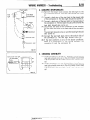
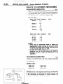
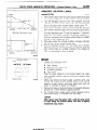
2. CHECKING
SHORTCIRCUITS
(1) Remove the blown fuse connect the test light to the
disconnected
terminal. The test light should not come
on.
(2) Connect a lead wire of the test light to the power side
of the connector 0. The test light should not come on.
(3) Connect a lead wire of the test light to the load side of
the connector 0. The test light should come on and the
load light should also come on.
(4) Disconnect
the load at the connector
0 and connect
the test light lead wire to the load side of the connector
CD.
The test light should come on and the load light should
also come on.
(5) Connect the test light lead wire to the switch side of
the connecotr
0. The test light should come on.
(6) If the test conforms
to any of the above conditions,
there is a shortcircuit
in the wiring between
the
connector
0 and the connector
0.
?
4,
1680241
3.
Self
power
test
light
Switch
ON
OFF
1680242
) STB Revision
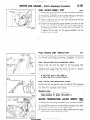
CHECKING
CONTINUITY
(I) When the switch is in the OFF position, the self power
test light should come on or the ohmmeter
should read
0 R only when the terminals
2 and 3 are interconnected.
(2) When the switch is in the ON position, the self power
test light should come on or the ohmmeter
should read
0 LR only when the terminals
1 and 4 are interconnected.
8-20
WIRING
HARNESS
- How to Read Wiring Diagrams
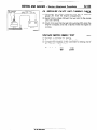
HOW TO READ WIRING DIAGRAM
HOW TO READ CONFIGURATION
NOEDBAE
DIAGRAMS
(1) Connector symbols
A wiring diagram shows the installed condition of each connector in a schematic style. The connectors are
shown and classified as follows, depending on their locations and are marked by connector symbols.
In case connectors of the same shape (same number of wires) are centralized, their colors are indicated for
identification.
Examp’e
: p.!-
f.~~~~
~;~~o,
Connector’s unique number
(serial number)
A : Engine compartment
B : Interior and frame
C : Instrument
panel
Main
fusible
link
A-03
A-o4 > 4WD indicator switch
A-05
Automatic
transmission
temperature
switch
oil
I
Same
diagram
connector
and
No. is used in the wiring
the circuit
diagram.
I
Indicates color of the
A-58 connector.
I
1 ST6 Revision
indicates
that the connector
is located
in the
WIRING
HARNESS
- HOW to Read Wiring
Diagrams
8-21
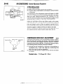
(2) Identification
of connectors
differing according
to different vehicle specifications
Without wiring harness connectors, the inter-device or -wiring harness connectors which vary in shape or
position on different vehicle specifications are given the specification-dependent
connector identification svmbol (lower case alphabet) after a serial number.
For detailed information on this specification-dependent
symbol, refer to Item (8) under “HOW TO READ
CIRCUIT DIAGRAMS”.
(3) Indication of standard mounting positions of harnesses
The standard mounting positions of harnesses are shown with the mark * in wiring harness configuration
diagrams.
(4) Indication of ground point
The position of ground points are shown in wiring harness configuration diagrams. For detailed information on
the ground portion, refer to ELECTRICAL SYSTEM PARTS LOCATION (Grounding).
7
Referto item (3)
Ground symbol
/ STB Revision
8-22
WIRING
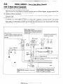
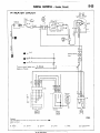
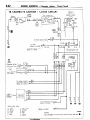
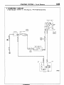
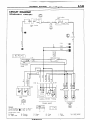
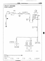
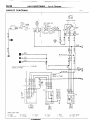
HOW TO READ CIRCUIT
The circuit diagrams
HARNESS
-
How
to
Read
Wiring
Diagrams
DIAGRAMS
are functionally
separated.
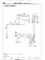
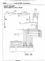
(1) Indication of circuit connected
to another circuit
When the circuit in a circuit diagram connected to another circuit in a different diagram, the page number of that
different diagram is indicated so that it can be referred to.
(2) Indication of device connections
The circuit diagram shows whether
a device harness connection
is one with an attached cable or is a direct
connection
type.
(3) Indication of connectors
in circuit diagrams
A connector
in a circuit diagram is shown
in a frame and is assigned
a connector
symbol. This symbol
corresponds
to the symbol in a wiring harness configuration
diagram so that the connector
location can be
known easily. An intermediate
connector
has its female side only shown as a rule. However
both of the male
and female sides are shown when they differ in wiring color.
Refer to Items (2) and (3).
The frame shows the connector is not touching the symbol
of a device,
and indicates
that
the device harness
connection
is one with an
attached
cable.
Refer to Item (2)
If a frame showing
a connector
touches
the
symbol
of a device ?. it indicates
that the device harness connectlon IS a direct connec-
Indicates
direct grounding
the device to the bodv.
tion type.
Ignition
1
*I RL **2-RL
1
BI
L
r------B-39
43
Refer to item
Indicates
that
nectar.
(3)
this
connector
1 STB Revision
switch
RL
Z-RL
B
BRL*I
RL*2
is a B-39
con-
Dome
light
/
17
/B-6&
RB-
(RG) - (RB)
(REV 1 I (GR)
B-68b
L-2
B-35
I
I
--------_
---__---___----
--------
31103LI
_
Refer to Item (1)
On a circuit connected
to another
circuit the
names of devices
to which the circuit is connected and pages on which diagrams
of such
another
circuit appear
are indicated.
1
from
WIRING
HARNESS
-
BO Read
HOW
Wiring
8-23
Diagrams
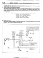
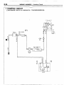
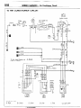
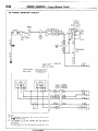
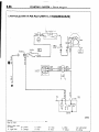
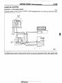
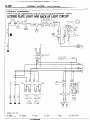
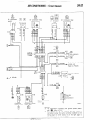
(4) Indication of fuses, fusible links and centralized relays
The fuses and fusible links in a circuit diagram are indicated by a wave symbol (-) and a double wave symbol
(~1, respectively. At a centralized junction, the fuses are given fuse numbers and centralized relays are given
connector symbols.
Example
of centralized
junction
symbol:
A - 01 x
Centralized junction
Connector’s unique
Connector symbol
indication symbol
number (serial number)
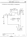
(5) Indication of ground point
The ground point in a circuit diagram is marked by a ground symbol, making it possible for you to refer to a
wiring harness configuration
diagram and to ELECTRICAL SYSTEM PARTS LOCATION (Grounding).
(6) Indication of wires
In a circuit diagram, the wire diameter and wire color are shown for each wire. If there are several wires
of the same color in a connector, their wire color indication
symbols should be such symbols as “I and
“2 for identification.
On connectors like this one given a central-
to CENTRALIZED
1shaoe. etc.
JUNCTION
for connector
-I
Headlight
ignition switch
relay
Dome light
B-68b
I
II
I
B-35
P:8-47)
I ’
BI
0
III-
L
B-39
RL
2-RL
B
IEU
2I
-----____________
- - - - - _ _ _ _ _ __
_ _ _ _ _
Refer to Item (5).
Refer to Item (6)
The connector
B-39 has two wires identical
in color (RL), so they are given identification
symbols *I and *2 in order to distinguish
them.
1 ST6 Revision
8-24
WIRING
HARNESS
- How
to
Read Wiring
Diagrams
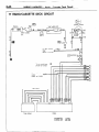
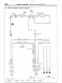
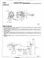
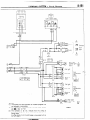
(7) Indication of shielded cables
A shielded cable used , for example, in an electronic control circuit for prevention of malfunctions
that may
otherwise be caused by radio interference is indicated by a solid line sandwiched between dashed lines ( E).
(8) Indication of specification-dependent
connectors
With regard to harness connectors, the inter-device and -harness connectors which vary in shape or position on
different vehicle specifications,
such as those with rear wipers and turbocharger and those without turbocharger, are given a specification-dependent
connector identification symbol (lower case alphabet) following the
connector symbol.
Example:
A - Ola
Specification
a : Vehicles
b : Vehicles
c : Vehicles
d : Vehicles
- dependent
connector
identification
with a manual transmission
with an automatic
transmission
with a power window
without a power window
(9) Shapes of connectors
The connector shapes are indicated by simplified symbolic
connectors, refer to HOW TO IDENTIFY CONNECTORS.
marks.
For distinction
symbol
between
male and female
Refer to Item (8)
The b at the end of the connector symbol
is a specification-dependent connector
identification symbol and indicates that
Ignition switch
Headlight
relay
STB Revision
I
the connector
is used for vehicles
automatic transmission.
Dome light
B-68a
B-68b
with’
WIRING
HARNESS
-
How
to
Read
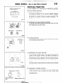
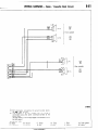
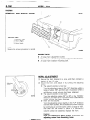
IDENTIFYING
Position
improper
of guide to prevent
connection
8-25
Diagrams
CONNECTORS
In circuit diagrams,
the connectors
are indicated
by symbolic
marks which show the number of their wires and whether
they
are male,or female connectors.
(1) Number of connector
wires
The number of divisions
in the connector
diagram indicates
the number of wires. A cross in a division, however,
indicates
the position of a guide to prevent improper connection.
The
connector
shown here, therefore,
is a g-wire connector.
fl!liB
9-wire
Wiring
connector
1680219
(2) Identification
of male and female connectors
Connectors
drawn with double outer lines are male, and those
with single outer lines are female.
jpg$&’
R
-y
Male
On-vehicle
v
terminal
connector
R
Female
terminal
Connector
in
wiring diagram
I
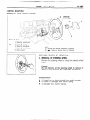
(3) Connector
direction
The connector
marks show on-vehicle
from the direction shown here.
connectors
as viewed
1680220
(4) Identification
of
The color codes
viewed
at their
illustrated
here.
joining surfaces
so the terminals
r
NOTE
The color codes
identical.
connector
terminals
of a pair of connectors
(male and female), if
joining surfaces,
will appear symmetrical
as
When the connectors
are connected,
their
are put together in the way a book is closed,
of identical codes are connected
together.
of male and female
connectors
are not always
16R0459
Guide to prevent
connection
Double
male.
@
lines
indicate
(5) Identification
of sealed connectors
Identification
of round, sealed connectors
(water-proof
pin terminal connectors)
used in radiator fan motor circuits, turbo
circuits,
etc. is accomplished
by the same
method
as
described
above.
improper
Numb&ions
Indicates
number
of wires
36KO37
/ STB Revision
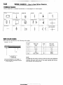
8-26
WIRING
SYMBOLIC
Various
HARNESS
- HOW to Read Wiring
Diagrams
MARKS
equipment
is indicated
Battery
Body ground
Fuse
Equipment
Fusible link
Motor
symbolically
in circuit idiagrams
as shown
Single bulb
Resistor
Speaker
Coil
below.
Capacitor
Diode
ground
~
Transistor
4
4
Crossing of lines
with conron
-1~
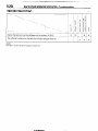
WIRE COLOR CODES
Wire colors are identified by the following color codes.
Example:
1.25 - GB
Code
Wire color
Code
Wire color
B
Black
Brown
LI
Light blue
0
Oranqe
Br
L
1 Gr
1
Grav
I
I
Blue
Light green
L
Lg
1.25: Wire size (mm2)
F: Flexible wire
T: Twisted wire
(1) No code indicates 0.5 mm2(.0008 in.*).
(2) Cable color-code in parantheses indicates
0.3 mm* (.0005 in.‘).
I
1
P
R
i
1
I Y I
W
Red
I
Yellow
White
I
NOTE
If a cable has two colors, the first of the two color code characters
indicates the basic color (color of the cable coating) and the second indicates the marking color.
STB Revision
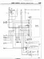
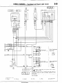
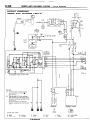
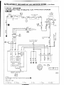
WIRING
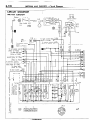
OVERALL
WIRING
HARNESS
DIAGRAM
) STB Revision
- Overall
Wiring
Diagram
8-27
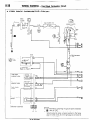
NOBDC-‘3
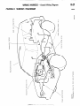
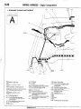
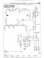
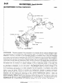
8-28
WIRING
HARNESS
- Engine
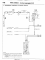
Compartment
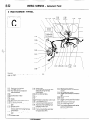
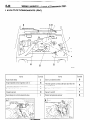
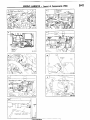
1 ENGINE COMPARTMENT
Connector
symbol
A
AA156
;:::I Main
fusible link
;:::I 4WD indicator switch
A-05 Automatic transmission
oil
temperature
switch
A-06 Back-u light and 4WD indicator
A-07)wiring
f!arness and cord
assembly combination
;:g> Back-up light switch
A-l 0 OD-OFF solenoid
A-l 1 Pulse generator
A-l 2 Front wiring harness and
transmission wiring harness
combination
A-13 Air conditioner solenoid valve
A-l 4 Front wiper motor
A-52
A-28
A-29
A-34
A-35
Auto choke relay
Front wiring harness and air
conditioner wiring harness
combination
Headlight washer motor
Front combination
light (L.H.)
Light control relay
Dedicated fuse (Upper beam
indicator circuit)
Headlight (L.H.)
Condenser fan motor
A-40
Condenser
A-55
A-l 7 Checker
A-18 Diode
A-19 Brake fluid level sensor
A-20 Front harness and back-up light
A-21 land 4WD indicator wiring
harness combination
it;;> Sub fusible link
A-24 Carburetor assembly
A-25 Control wiring harness and air
conditioner wiring harness
combination
A-26 Front wiring harness and control
wiring harness combination
A-27 Device box
1 STB Revision
A-53
A-54
A-30
A-31
A-32
A-33
fan motor relay
WIRINGA-06
;
,.
I
I
A-08 A-1 0 A-12
,I
A-48
I
HARNESS
A-14
1 A-15
I,
I
- Engine
8-29
Compartment
8
/
WI
&-ii&
A-39
A-37
’
A-35
A41
i-$
Ignition coil
A-44
A-45 Magnetic clutch
A-46 Water temperature
sensor (FBC circuit)
;rii}Alternator
A-49 Water temperature switch (Air conditioner circuit)
A-50 Water temperature gauge unit
A-51 Water temperature switch (OD control circuit)
A-52 Oil pressure gauge or oil pressure switch
Low pressure switch
$3
Ai34
A!33
J-3:
36W618
A-55
A-56
A-57
A-58
A-59
Headlight (R.H.)
Front harness and air conditioner
combination
Front combination
light (R.H.)
Front washer motor
Oxygen sensor
wiring harness
Remarks
(1) The mark * shows the reference mounting
position of
wiring harness.
(2) For information
concerning
the ground points (example: q ), refer to P.8-7.
1 STB Revision
8-30
WIRING
HARNESS
- Interior
B-01
Be03
and Frame
2 INTERIOR AND FRAIVIE
Connector
symbol
1
B
B-32
B-33
\
B-29
\
“-I2
B-05
\
9
B-06
B-08
\ B-p7 \
B-p9
B-l 0
1
AB-26
B-27
B-22
STB Revision
H-21
-1
36W617
WIRING
HARNESS
B-01 Dome light
B-02 Door switch (R.H.)
:::3 Rear speaker (R.H.)
B-05 Defogger (-)
B-06 Back door wiring harness and license plate light wiring
harness combination
B-07 Rear wiper motor
B-08 Rear washer motor
B-09 Defogger (+)
B-l 0 Back door wiring harness and defogger cable (+)
combination
B-l 1 Rear side marker light (R.H.)
B-12 Frame wiring harness and back door wiring harness
B-13)combination
B-14 Rear combination
light (R.H.)
&z}License
plate light (R.H.)
Remark
The mark + shows
harness.
the reference
mounting
position
of wiring
STB Revision
- Interior
8-31
and Frame
/&}License
plate light (L.H.)
B-19 Back door lock actuator
B-20 Rear combination
light (L.H.)
B-21 Fuel gauge unit
B-22 Rear side marker light (L.H.)
B-23 Front wiring harness and frame wiring
combination
;:g
E$
Rear speaker (L.H.)
:::g>
B-30
B-31
B-32
B-33
Door switch (L.H.)
Power window main switch
Power window motor (L.H.)
Power window motor (R.H.)
Power window sub switch
harness
8-32
WIRING
3 INSTRUMENT
Connector
HARNESS
- Instrument
Panel
PANEL
c-04
symbol
C-06
C
C-65
C-64
C-63
C-61
CL57 C-b6 C!55
Remarks
For information
refer to P.8-7.
concerning
the ground
points
(example:
q
d54
c!5
),
C-01 Back door lock switch
C-02 Defogger switch
C-03 Kev reminder and seat belt
warning buzzer
c-04
Combination
meter
pi;’
C-l 8 Heater relay
C-l 9 Air conditioner wiring harness
and front wiring harness
combination
E:$)}Air conditioner relay
C-31 Blower motor resistor
C-32 Dedicated fuse (Air conditioner
circuit)
C-33 Air conditioner switch
C-34 yl;Jer control lonob illumination
C-08 Diode
C-09 Rear wiper and washer switch
r&~}Oil
pressure gauge
C-12 f;hybination
gauge illumination
$:;;IThermostat
$:;;IFeed back
carburetor control unit
C-26 Front speaker (R.H.)
C-27 Front wiring harness and roof
wiring harness combination
C-28 Automatic free-wheeling
hub
indicator control unit
C-29 Seat belt warning timer
C-30 Front wiring harness and door
wiring harness (R.H.)
combination
c-35 Blower switch
C-36 Clock
c-37 Heater control panel illumination
light
C-38 Ashtray illumination
light
c-39 Air conditioner switch
illumination light
c40 Front wiring harness and center
panel wiring harness
combination
C-l 3 Blower switch
C-14 Combination
gauge wiring
harness and front wiring harness
combination
C-15 F;hybination
gauge illumination
C,::F}Voltage
meter
[ STB Revision
“3’
‘.
WIRING
cy50
C149
Cl48
HARNESS
- Instrument
Panel
c-47
El$,}Cigarette
lightet
C-43 Cigarette lighter illumination light
E::$ Radio
C-46 Shift position illumination light
C-47 Inhibitor switch
C-48 OD-OFF switch
C-49 Parking brake switch
C-50 Seat belt switch
C-51 Hazard switch
Column switch
C-54 Key reminder switch
C-55 Ignition switch
C-56 Stop light switch
E3
Ision
C-57 Dimmer control switch
C-58 Front wiring harness and door
wiring harness (L.H.) combination
C-59 Turn-signal flasher unit
C-60 Power window relay
C-61 Intermittent wiper relay
C-62 Hazard flasher unit
C-63 OD-OFF relay
C-64 Headlight washer motor relay
C-65 Front speaker (L.H.)
8-33
8-34
WIRING
MARNESS
1 STARTING CIRCUIT
(VEHICLES WITH A MANUAL
- Starting
Circuit
TRANSMISSION)
Ignition
switch
TA RT
Battery
Main
link
@.25B+
L1!
zcl
fusible
A-23
mw BY
Sub fusible link
(IGN - SW)
M
2
M
I
7 A-15
BIT/B
F=
A
Starter
1 STB Revision
37W620
WIRING
HARNESS
(VEHICLES WITH AN AUTOMATIC
Battery
-p
8-35
Circuit
TRANSMISSION)
Sub fusible link
(IGN . SW)
A-23
Main
fusible
link
- Starting
Ignition
switch
lrril‘I
1.25-B
-5-w
A-02
U
c-47
a 1 2-BY
Ia- 1
2-BY
1
Inhibitor
switch
N
2-BY,2-BY*2
2-BY
2-BY*l
P
BYBY
fTl
37W613
Remark
For information concerning
the ground
refer to P.8-7.
Wiring color code
Br: Brown
8: Black
LI: Light blue
0: Orange
points (example:
G: Green
P: Pink
) STB Revision
0 ).
Gr: Gray
R: Red
L: Blue
Y: Yellow
Lg: Light green
W: White
8-36
WIRING
2 IGNITION
HARNESS
- Ignition
Circuit
CIRCUIT
A-23
Main
fusible
link
Batterv
/
Sub fusible
(IGN * SW)
link
Ignition
switch
IR
I
i
r
mw
Distributor
To combination
meter
(TACHO)
[Refer to P.8-52.1
J A-44
37W609
Remark
For information
refer to P.8-7.
concerning
Wiring color code
B: Black
Ll: Light blue
the ground
Br: Brown
0: Orange
points
(example:
G: Green
P: Pink
/ STB Revision
q
),
Gr: Gray
R: Red
L: Blue
Y: Yellow
7
Lg: Light green
W: White
‘:
WIRING
3 CHARGING
HARNESS
- Charging
8-37
Circuit
CIRCUIT
Ignition
switch
.n
S‘
Main
fusible
link
Battery
I
3
cl
m’ L
A-02
Sub fusible link
(IGN - SW)
A-23
,
‘I81
m
3
3
c:
-22
3
c!J
t
El
A-48
Alternator
I
To turn signal flasher
unit [Refer to P.8-49.1
1
Comornatron
Remark
For information
refer to P.8-7.
concerning
Wiring color code
B: Black
LI: Light blue
the ground
Br: Brown
0: Orange
.
points (example:
G: Green
P: Pink
/ STB Revision
q
J
3
a
I
6
Multipurpose
fuse
meter
37W605
),
Gr: Gray
R: Red
L: Blue
Y: Yellow
Lg: Light green
W: White
8-38
WIRING
HARNESS
-
4 FEED BACK CARBURETOR
Battery
Main
fusible
link
Feed
Back
Carburetor
Circuit
CIRCUIT
m’
A-02
efl
EEI
j
i
-1.25-B-
Sub fusible
L
W
link
Ignition
BW
switch
uA-2i
I
I:
h
W
a
r
A-28
zix--I
c:
qi
To alternator
[Refer to P.8.37.1 1
-26c-1
ziE2
I
BW ".
r
Feed back
solenoid valve
YG
1.25-BW"'
Slow cut
solenoid valve
YL
1.25-BW*'
c
w
2-BW wQ
I
I
I
yL ,0
P
Auto choke
heater
-hrottle
iensor
position
1 A-24
Carburetor
assembly
Remarks
(1) For information
concerning
the ground points (example:
0). refer to P.8-7.
(2) The symbols 0, 0 etc. indicate that the wiring is connected (using the same numerical symbol) to the facing
page. (In other words, 0 on the right page is connected to
0 on the left page.)
STB Revision
WIRING
HARNESS
- Feed Back Carburetor
8-39
Circuit
Ignition
coil
) _ ,E3
$-To
q
A-42
A-4
vacuum
solenoid
valve [Refer to P.8-57.1
7
BR
cl
c-2 ‘Af r
,
I
I
I
I
I
I
;
:
;
:
0.85-BW
YG
YL.
I
RW,
II
II
(I
A-4
A-9
A-3
A-6
A-5
B-l 1
B-6
B-9
B-IO
I
I I- - - - -. -_ __ __
L---__._._
1I ! !
I i-----,
+L----J
Feed back
carburetor
control unit
B
B-l
B-2
B-l 2
B-3
B-13
B-8
B-7
B-5
I
Vacuum
switch
Device
box
L
control
L
A-46
Water
temperature
sensor
1 STB Revision
solenoid
8-40
WIRING
HARNESS
- Layout
of Components
WC)
LAYOUT OFCOMPONENJS [FBC)
CD
II
A
\\
5FU131
Items
Items
Symbol
Auto choke relay
J
Slow-cut
solenoid valve
Engine speed sensor
(Ignition coil 0)
G
Feed back carburetor
control unit
K
Throttle opener control solenoid valve (for the
air-conditioner)
Feed back solenoid valve
I
C
Throttle
Oxygen sensor
I
H
Vacuum switch
Secondary
I
I
Throttle
solenoid
air control solenoid valve
opener
valve
contr
Symbol
position sensor
1 Water temperature
sensor
D
A
I
E
I
F
I
B
WIRING
sensor
U’S) /
control
HARNESS
- Layout
5FUl
unit
w1515
1/
LTBI levision
of Components
(FBC)
8-41
8-42
WIRING
5 OVERDRIVE
HARNESS
CONTROL
- Overdrive
Control
System
Circuit
SYSTEM CIRCUIT
/ Sub
fusible
link
Ignition
$in
switch
fusible
a
I
To combination
meter
[Refer
to P.8-52.1
~
To alternator
[Refer
to P.8-37.1
~
0.85-W
To column
[Refer
to
~
0.85-RL
switch
P.8-51.1
1
0.85-W
i
Remarks
(I)
For information
concerning
the ground
points
(example:
0).
refer
to P.8-7.
(2)
The
symbols
0,
0,
etc.
indicate
that
the
wiring
is
connected
(using
the same
numerical
symbol)
to the
facing
page.
(In other words,
0 on the right page is connected
to 0 on
the left page.)
1 STB Revision
Multi-purpose
fuse
Combination
RLI
-7
1 IyRw
meter
4
1 1 I
WIRING
HARNESS
- Overdrive
Control
System
8-43
Circuit
*I
Inhibitor
Water
temperature
switch
1
I
OD-OFF
relav
r
C--63
RL
)
To back-up light
[Refer to P.8-45.1
2-BY
9
3
4
5
To starter relay
[Refer to P.8-34, 35.1
t
I
IA-12 @@
t
VRR
L
1
r
A-05
Automatic
transmission
oil temperature
switch
switch
OD-OFF
solenoid
llR)3
[RILRI
Wiring color code
B: Black
Br: Brown
LI: Light blue 0: Orange
-10
G: Green
P: Pink
G;; ;ZJ
1 STB Revision
L: Blue
Y: Yellow
Lg: Light green
W: White
37w019
8-44
WIRING
HARNESS
Tail Light. Position
Light, Rear Side Marker
Light,
License Plate Light and Back-Up
Light Circuit
-
6 TAIL LIGHT, POSITION LIGHT, REAR SIDE MARKER LIGHT,
LICENSE PLATE LIGHT AND BACK-UP LIGHT CIRCUIT
?I w19
eF=7
I 1 1 I
nwr
II
Battery
Sub
EiT
n1.25-Bn
fusible
link
II
Main
fusible
link
To turn-signal
flasher
unit
O-85-RL
i
I
I
I
Inhibitor
switch
A-09
combination
i
1
I
I
combination
000
Back-up
switch
light
Em
Wiring
color
code
g: Black
Ll: Light
blue
Br:
0:
Brown
Orange
G: Green
P: Pink
1 STB Revision
Gr: Gray
R: Red
L: Blue
Y: Yellow
Lg:
W:
Light
White
green
WIRING
HARNESS
-
Tail Light,
Position
License
Plate
Light
Light,
Rear
and Back-Up
Side Marker
Light.
Light Circuit
8-45
fl!FEEl
Column
I
switch
Lighting
switch
Light control
relay
F-GW -GW
B-l 2
B-l 1
Tail light
Tail light
Back-up
light
Rear
$ combination
light
(R.H.)
RG
RI.G
‘El3
Tail light
Tail light
Back-up
light
I
Remarks
(1) The broken lines are applicable to models equipped wrtn
an automatic transmission.
(2) For information
concerning
the ground
points (example: 0 ). refer to P.8-7.
(3) The symbols
0, 0, etc. indicate that the wiring is
connected
(using the same numerical
symbol) to the
facing page.
(In other words, 0 on the right page is connected to 0 on
the left page.)
,
I
) STB Revision
GW
IBl
Rear side
B-22
37W023
Rear
combination
fight
(L.H.)
8-46
WIRING
HARNESS
-
Headlight
Circuit
1
7 HEADLIGHT
CIRCUIT
M-!l
Battery
-1.25-B1
Main
link
il IRI viI!YR
I‘i
Sub fusible
link
A-02
5-w
5-w m5-w
M 0.5-G
2-R
U
A-23
fusible
F
2-B
71' 0
[ES
$$J
A-33
Dedicated
1 c-05
fuse
1
BEAM
1 ('R;
J
Combination
meter
“I w
C-52
-32
A-34
Light
relay
control
Lighting
switch
Dimmer
switch
Column‘
Remark
For information
concerning
the ground
POintS
(example: 0 ), refer to P.8-7.
Wiring color code
B: Black
Ll: Light blue
A-55
Br: Brown
0: Orange
Passing
switch
(L.H.)
switch
(R.H.)
Headlight
37W621
9
G: Green
P: Pink
1 STB Revision
x2
m
Gr: Gray
R: Red
L: Blue
Y: Yellow
Lg: Light green
W: White
WIRING
HARNESS
- Dome
8-47
Circuit
Light
8 DOME LIGHT CIRCUIT
A-02
Battery
r
1.25-B
\
3
Main
fusible
Sub
5-w rl5-w
u
2-w
m
fusible
link
0.5-G
2-R
A-23
link
To column
[Refer
to
Multi-purpose
fuse
switch
P.8-46.1
1.25-GB
2-R
&
m
At
Combination
meter
1.25-GB
To hazard
flasher
unit
[Refer
to P.8.49.1
I--
C-27’
B-01
Dome
light
(L.H.)
(R.H.)
Door
switch
37W620
Remark
For information
refer
to P.8-7.
Wiring
B: Black
LI: Light
color
blue
concerning
the
ground
points
(example:
0
),
code
Br: Brown
0: Orange
G:
P:
Green
Pink
1 STB Revision
Gr: Gray
R: Red
L: Blue
Y: Yellow
Lg:
W:
Light
White
green
8-48
WIRING
HARNESS
9 TURN-SIGNAL
AND
A-02
-
a3
1.25-B-
Main
fusible
Hazard
Light
Circuit
LIGHT CIRCUIT
Sub fusible
1
link
0.5-G
A-23 5-W
l-l
(5-W
8
Turn-Signaland
HAZARD
1
m
Battery
r
-
1 81
El3
Ignition
2-R
switch
2-W
link
A-32
GW To lighting
switch
e [Refer to P.8-46.1
*
2-R
2-RW
I-
2-B
To column switch
[Rear to P.8-461
I
t
'I
7
l.ZS-tit3
-
0.85-GY
+a
I_ \
(Bl -6
0.85-GL
LO
Gw -@
I
rn&
lzil
A-57
Turn-signal
and
hazard light
Front
Turn-signal
and
hazard light
Front
combination
light (R.H.)
el
00
n
STB Revision
b-d
5
c-05
J CL
--.
I- \I--
IG
Combination
meter
WIRING
HARNESS
- Turn-Signal
OR
0 RI.
Turn-signal
Turn-signal
flasher
unit
I
I
switch
and
Hazard
GO
0 0.3
iazard
Hazard
flasher
unit
r
E
L:
ci
Light
8-49
Circuit
switch
“1
*2
1
C-62
C
Turn-signal
and hazard
->
&
light
Rear Combination
light (R.H.)
light
Rear combination
light (L.H.)
mm
c-57
Dimmer
switch
control
OL
Em B
WL
(1) For information
concerning
the ground points (exam“em~:~s~
) refer to P.8-7.
(2) The symbols 0, 0, etc. indicate that the wiring
is
connected
(using the same numerical
symbol) to the
facing page.
(In other words, 0 on the right page is connected to 0 on
the left page.)
m
Wiring color code
B: Black
LI: Light blue
Br: Brown
0: Orange
37W825
-2
m
EJ
G: Green
P: Pink
Gr: Gray
R: Red
L: Blue
Y: Yellow
Lg: Light green
W: White
I
STB Revision
8-50
WIRING
HARNESS
- Stop Light
Circuit
IO STOP LIGHT CIRCUIT
1
In3
Sub
fusible
link
A-07
Main
link
fusible
Multi-purpose
fuse
0.85-GR
0.85-G
c-51
0.85-G
Hazard
switch
1.85-WG
$R
WL
1 1 1
’
,I
,I
(
Turnsignal
switch
Rear
light
Remark
For information
refer
to P.8-7.
concerning
Wiring
color
code
B: Black
LI: Light
blue
the
Br: Brown
0: Orange
ground
points
(example:
G: Green
P: Pink
1 STB Revision
0
cdmbination
(L.H.)
Rear
light
c:mbination
(R.H.)
),
Gr: Gray
R: Red
L: Blue
Y: Yellow
Lg:
W:
Light
White
green
WIRING
HARNESS
11 INSTRUMENT
-
Instrument
Panel
Wumination
PANEL ILLUMINATION
Battery
CIRCUIT
Sub fusible
5-w
Main
fusible
5-w l-75-W
LA-23
m
8-51
Circuit
link
0.5-G
2-R
link
@L
CA
M’
A
A-22
rx
c-l
Y$lO
I
Optical
fiber
I
Multi-purpose
fuse
control
illumination
0
3
a
.ight contr
clay
c-4o1l
knob
light
Combination
gauge
Illumination
ligl
control
switch
&01BY
7t
Shift-position
lmer
C-38
4
Ashtray
illumination
Cigaretty
lighter
minagn
n+
Hegpane
illumination
light
63
_
’ Clock I
illumination
(1) The broken lines are applicable to models equipped with
an automatic transmission.
(2) For information
concerning
the ground
points (example: 0 ), refer to P.8-7.
Wiring color code
B: Black
Br: Brown
G: Green
Gr: Gray
P: Pink
R: Red
LI: Light blue
0: Orange
1 STB Revision
Combination
illumination
light
meter
light
37w '62;
L: Blue
Y: Yellow
Lg: Light green
W: White
WIRING
HARNESS
- Meter
Circuit
12 METER CIRCUIT
1
m
A-02
Sub fusible
link
Ignition
switch
15-w
Main
link
fusible
-
--
\
A-22
‘1
m
-ffiFirmer
control
[Refer to P.8-511
I 0 column :
[Refer to P.E
BY
4
@/
Multi-purpose
fuse
I
To turn,signal
switchfd,,, (bYI ,
[Refer to P.8-491
1
To seat belt timer
[Refer to P.8-661
G 1
To seat belt warning
buzzer [Refer to P.8-661 M
I
To alternator
0.85tW
fRefer to P.8-371 41D\ 1
‘o dimmer, passir, “,, ,
witc :h and light control Ir r n ! , I
~ -_
clay [Refer to P.8461
Kb
To dome light
[Refer to P.8-471 4
To door yi~“,h,,_(RG)
I
I
4
I
ID,.&-* +,.
1
YBdD
I
q
3_---_-ly-J
Ir
t
Combination
1 STB Revision
meter
m
”
WIRING
HAFNESS
-
Meter
8-53
Circuit
O&y-ssure
[Eal
> El
Oil pressure
gauge unit
YRB BRYR
ElxQ
A-20
I.+
A-03
A-06
4WD
indicator
’
--
.-
I
I
I
E
1
,’
I
I
*
- -,,-
-
-
-
-
--
YB
L,
I
4
Brake fluid
level sensor
0.85-B
T
-I m-w
I
I
k-1
A-04
A-07
rA
fs
I
Ei
switch
Jo
cigarette lighter
[Refer to P.8-621
Parking
switch
? I
brake
I ’
I
I
I
I
I
1
' 1
I
I I
I 1
B-23
, I I I
I !
Fuel gauge
unit
Water
temperature
gauge unit
37W617
les with combinatior
Combination
gauge
(2) %?zgdeash and dot line (- -) indicates vehicles wit1
automatic free-wheeling
hub indicator.
(3) For information
concerning
the ground points (er
ample:n),
refer to P.8-7.
(4) The symbols@,@,
etc. indicate that the wiring i
connected
(using the same numerical
symbol) tl
the facing page.
(In other words,Oon
the right page is connecter
to@ontheleft page.)
Wiring color code
B: Black
LI: Light blue
Br: Brown
0: Orange
G: Green
P: Pink
1 STB Revision
Gr: Gray
R: Red
L: Blue
Y: Yellow
Lg: Light green
W: White
8-54
HARNESS
WIRING
- Horn Circuit
13 HORN CIRCUIT
/I
1
m
Battery
Sub fusible
A-23
1
m 0.5-G
5-w/-75-w
3
Main
fusible
u
link
Ignition
switch
Z-W
link
OFF
]AM
ACC]
Multi-purpose
fuse
a
-i
::
C
,
To wiper motor
[Refer to P.8-59.1
A-3
Column
A-39
switch
37W608
Remark
For information concerning
the ground
refer to P.8-7.
Wiring color code
Br: Brown
B: Black
LI: Light blue
0: Orange
points (example:
G: Green
P: Pink
1 STB Revision
q
),
GI.: Gray
R: Red
L: Blue
Y: Yellow
Lg: Light green
W: White
WIRING
HARNESS
-
Heater
8-55
Circuit
14 HEATER CIRCUIT
*I BI
l!zEl
A’
lonition
switch
Battery
0
(Ignition
switch)
L
Multi-purpose
fuse
To turn
signal
flasher
[Refer
to P.8-49.1
unit4
-P---
H
M2
Ml
bFF
n
[
0.85-RL
Blower
motor
!!
C-18
M
I
Blower
i
\
Blower
resistor
switch
motor
T
LBLI
LRLW
El3
I
Heater
relay
8L
LRLR
El *2
*1
37W614
Remark
For information
concerning
refer
to P.8-7.
Wiring
color
code
B: Black
LI: Light
blue
the
Br: Brown
0: Orange
ground
points
G:
P:
(example:
Green
Pink
STB Revision
0
),
Gr: Gray
R: Red
L: Blue,
Y: Yellow
Lg:
W:
Light
White
green
8-56
WIRING
HARNESS
15 AIR CONDITIONER
- Air Conditioner
Circuit
CIRCUIT
Ignition
Main
fusible
I;..,,
Sub fusible
(Fuse B)
m
1
switch
link
+2
0.85-R
I
I
(lonition
switch)
I
I
,!..I
’ ’
T
unit ~ 0.85-RL
To turn signal flasher
[Refer to P.849.1
L
I
3-LRwQ
J
I
,
,0.85-LW
To cigarette
lighter
[Refer to P.8-62.1
0.85-WB@
FA2
Ml
Ii
Blower
Br: Brown
0: Orange
1C-18
M
bFF
Wiring color code
B: Black
LI: Light blue
Blower
motor
8
I
IY4JYl!!!a
f
1
switch
G: Green
P: Pink
lower
Gr: Gray
I?: Red
motor
T-
L: Blue
Y: Yellow
Heater
relay
Lg: Light green
W: White
STB Revision
II/
WIRING
HARNESS
- Air
Conditioner
8-57
Circuit
B 0.3
LvfL
ElFI
Air conditioner
relay
@
‘I
I
*2
H
Air :on!$!er
feed back carburetor
) to
control unit
85-Bw:o.85-Bw
0
0:
u
A-25
(Bl
rela
[Refer to P.8-39.1
Lw
20.85-BWr
ll 10.85-BWL&
A-13
*
Vacuum
valve
solenoid
@,0.85-WB
A-45
0.85-BWnBW
Is*la
Magnetic
clutch
(compressor)
U
Condenser
blower motor
Condenser
blower
motor relay
Water temperature
switch
BY
rl
-I37W611
Remarks
(1) For information
converning
the ground
points (example:(l)n),
refer to P.8-7.
(2) The svmbols
0, 0, etc. indicate that the wiring
is
connedted
(using the same numerical
symbol) to-the
facing page. (In other words, 0 on the right page is
connected
to 0 on the left page.)
) STB Revision
8-58
WIRING
HARNESS
16 WIPER AND WASHER
- Wiper
Circuit
Washer
LW
1
m
CIRCUIT
IL&
Battery
and
Sub fusible
Ignition
link
-1.25-BAs2
Main
fusible
switch
2-R
5-w r--(5-w
Z-W
link
To lighting
switch
Light
control
relay
Multi-purpose
fuse
@
I-2-B
Intermittent
wiper
control
relay
r
Remarks
(1) For information concerning the
ground points (example: q ).
refer to P.8-7.
(2) The symbols 0.0, etc. indicate
that the wiring is connected (using
the same numerical symbol) to the
facing page.
(In other words, 0 on the right
page is connected to 0 on the left
page.)
r
C-64
Headlight
washer motor
Wiring
I
1
Headlight washer
motor relay
color code
B: Black
LI: Light blue
Br: Brown
0: Orange
G: Green
P: Pink
/ STB Revision
Gr: Gray
R: Red
L: Blue
Y: Yellow
1
Lg: Light green
W: White
9
WIRING
HARNESS
m --
- Wiper
and
Column switch
FronthiDer
switch
Washer
8-59
Circuit
-1
BP
118 B
f!EEl
Headlight
washer
switch
I
-_I
Rear wiper and
washer switch
I
1
z-09
c-53
@4-zo-(YL)
@JY'
@- BR
@- Lw
-1 j
A-14
I
1A-58
I
Frontwasher
motor
Front wiper
motor
Rearwasher
motor
WB
Q I.
Rear wiper
motor
37W024
-
1 STB Revision
S-60
WIRING
HARNESS
17 RADIO/CASSETTE
Battery
A-02
_
/ Cassette
Deck
Circuit
DECK CIRCUIT
L1
1
EQ3
1
lm
Ignition
Sub fusible
1.25-B
A-23
\
rlin
- Radio
5-*5-w
link
0.5-G
m
2-w
fusible
To light control
relay
[Refer to P.8-461
To air conditioner
[Refer to P.8-561
To combination
4
meter
[Refer to P.8-521
c
BY
DIN Cable
JC
3:
A-C-1
Tape
Radio
player
1 STB Revision
-7
switch
WIRING
HARNESS
- Radio / Cassette
8-61
Deck Circuit
(R.H.)
Front speaker
1
(L.H.)
Rear speaker
37W618
Remarks
(1) For information
concerning
the ground points (example: 0 ), refer to P.8-7.
(2) The symbols 0, 0, etc. indicate that the wiring
is
connected
(using the same numerical
symbol) to the
facing page.
(In other words, 0 on the right page is connected to 0 on
the left page.)
Wiring color code
Br: Brown
G: Green
Gr: Gray
B: Black
I?: Red
P: Pink
LI: Light blue
0: Orange
-
1 STB Revision
L: Blue
Y: Yellow
Lg: Light green
W: White
8-62
WIRING
18 CIGARETTE
HARNESS
-
Cigarette
Lighter
/ Clock
Circuit
LIGHTER / CLOCK CIRCUIT
Sub
fusible
r-l E-f?
Ignition
link
‘)
switch
n
-u
yn;in
fusible
7-R
To light control
[Refer
to P.8-461
To radio
[Refer
to
To hazard
[Refer
to
flasher
P.8-491
\*I
relay
GW
P&601-,
unit4
3FI .LJ-
Pm
G
Multi-purpose
II
illumination
fuse
I
light
To heater
illumination
[Refer
to
control
light
P.8-511
Clock
1
J
h
6
CT
0:
Jc-36
To combination
[Refer
to P.8-521
Wiring
B:
Br:
G:
Gr:
L:
Lg:
Black
Brown
Green
Gray
Blue
Light
color
mete&
BY
1
code
green
LI:
0:
P:
H:
Y:
W:
Light
Orange
Pink
Red
Yellow
White
blue
To dimmer
[Refer
to
control
P.8-511
switch
Remark
For information
refer
to P.8-‘7.
M
BY
concerning
the
ground
points
(example:
0
1,
WIRING
19 DEFOGGER
HARNESS
- Defogger
CIRCUIT
Sub fusible
A-23
5-wn5-w
ynlin
8-63
Circuit
0.5-G
I
I ml
EEH
link
Ignition
U
fusible
switch
z-w ,
A
1
z
I
l%
7
N
(#IO
-22
u
To light control
~-RN
w
relay
[Refer to P.8-461
+!I00
Defogger
1.25-B
m
I
Ki .
4
m
1.25-BR
/
B-05 /
B
Q
z
A
pFJ
Bg
L-l
2-FB m
Multi-purpose
@fuse
D
3-B
U
B-13
BR
Q
i
m
of
A
To column switch
[Refer to P.8-461
LY!ii!T
Rheostat
x7.
Remarks
For information
refer to P.8-7.
concerning
the ground
points
Detogger
*I
switch
(example:a),
37W62’
Wiring color code
B: Black
LI: Light blue
Br: Brown
0: Orange
G: Green
P: Pink
1 STB Revision
Gr: Gray
R: Red
L: Blue
Y: Yellow
Lg: Light green
W: White
?
8-64
WIRING
20 POWER WINDOW
HARNESS,
-
Power
Window
Circuit
CIRCUIT
w
EEH
Ignition
- ..
I
81
switch
II
1
1.25-B
Main
link
fusible
Multipurpose
fuse
[Refor to P.8-491
, I-
(RL)
2-LR bg
Power window
main switch
I
I
-I
*1 1.25-R
*2 1.25-G
Remarks
(I) For information
concerning
the ground
points (example:m). refer to P.8-7.
(2) The symbols 0, 0, etc. indicate
that the wiring
is
connected
(using the same numerical
symbol) to-the
facing page.
(In other words, 0 on the right page is connected to 0 on
the left page.)
1 STB Revision
1.25-R
1.25-G
,@
,@
WIRING
R
B0
Power
motor
window
(L.H.)
bM
B-31
c
::
r
HARNESS
- Power
2-B
F
,
r
>
.I.
-I
Window
-
8-65
Circuit
To colunm switch
[Refer to P.8-511
washer relay
[Refer to P.8-581
Power
window
relay
IRL)
:=2-L,
04 2-L
g:
2-B
2-RL
Power window
sub switch (R.H.)
1.25-R
@*1.25-G
8*
37w003
Wiring color code
B: Black
LI: Light blue
Br: Brown
0: Orange
G: Green
P: Pink
1 STB Revision
Gr: Gray
R: Red
L: Blue
Y: Yellow
Lg: Light green
W: White
8-66
WIRING
HARNESS
-
Buzzer
Circuit
21 BUZZER CIRCUIT
nil1
Battery
-1.25-B
A-02
Sub fusible
-
‘I 01
IT8
link
Ignition
switch
0
Main
link
fusible
dhm
b-
Multi-purpose
OR Key reminder
A0 switch
[Refer to P.8-491
1
0
c-03 r
C
-CCl
z-CY
z-
a
m
c-50
3
P-P
P
mm-l
aa-cd
-.A
IC
-J
ski&t
switch
I.5
‘bb’
Key reminder
and seat belt
warning
buzzer
Combination
meter
Seat belt
warning timer
Remark
For information
refer to P.8-7.
37W607
concerning
Wiring color code
B: Black
LI: Light blue
the ground
Br: Brown
0.: Orange
points
(example:
G: Green
P: Pink
1 ST9 Revision
q
),
Gr: Gray
R: Red
L: Blue
Y: Yellow
Lg: Light green
W: White
WIRING
HARNESS
-
Automatic
Free-Wheeling
FREE-WHEELING
Battery
n
-5-w
Main
link
Indicator
System
HUB INDICATOR
Sub
171.
Hub
fusible
Circuit
B-67
SYSTFM
link
1 m2-G
m
fusible
rgntrron
Iz-w
- _I
swrtcn
ON
I
Pulse
generator
Multi-purpose
fuse
To column
[Refer
to
e
switch
P.8-461
z
1
::
m
C
0:
1
I
I
0
2I
’
-
I++m
c-07
1
Vehicle
speed
detective
circuit
Pulse
detective
circuit
I
EleAtrir
circuit
power
d&V+
-
LR
1
m
m
,:cAcJl
!!I
T-r-
m
q OE!
-
z-
C-06
-.I;
c-04
1
L
Combination
meter
r
Automatic
indicator
For information
refer
to P.8-7.
Wiring
B: Black
LI: Light
color
blue
free-wheeling
control
unit
concerning
the
ground
hub
37W610
points
(example:
0
).
code
Br: Brown
0: Orange
G: Green
P: Pink
STB Revision
“,;:
;;;Y
L: Blue
Y: Yellow
Lg:
W:
Light
White
green
WIRING
HARNESS
- Back Door Lock Circuit
23 BACK DOOR LOCK CIRCUIT
Battery
Sub fusible
_
$’
5
link
Multi-purpose
fuse
m
’
)
1.25F-G
A
-1.25-G
1.25F-R
2-LR -To
0
1.25-R
2-B
B-l 2
cza
I I
xx. .
77
B-24 [
cLL3
ALA
CVN
. .
77
m
-To
heater relay
[Refer to P.8-551
column switch
[Refer to P.8-511
0
I
Back door
lock actuator
Wiring color code
B: Black
Br: Brown
LI: Light blue
0: Orange
Remark
For information
refer to P.8-7.
G: Green
P: Pink
Gr: Gray
R: Red
/ STB Revision
L: Blue
Y: Yellow
37W602
concerning
the ground
Lg: Light green
W: White
points (example:
q
),
WIRING
HARNESS
- Centralized
896!
Junction
CENTRALIZED JUNCTION
Main
Fusible
Link
Circuit
Cable color
mm’ (ir?.)
continuous
Fusing current
Sub Fusible
current
A
40
A
190
Link
Circuit
Cable color
Fusible link size
mm7 (in.2)
continuous
Fusing current
Dedicated
Feed back carburetor
control circuit
1.25 (.0019)
Item
Permissible
circuit
Black
Fusible link size
Permissible
Alternator
Main circuit
A
current
A
Lighting circuit
Stop light, door lock
and heater circuit
Ignition circuit
Green
0.5(.0008)
Red
Green
0.85(.0013)
27
34
0.5(.0008)
27
100
150
100
Power window
circuit
Green0.5(.0008)
27
100
Fuse
Upper beam indicator circuit
Air conditioner
cixit
/
WIRING
Multi-purpose
Power
- Centralized
Junction
Fuse
supply circuit
Battery
Headlight
HARNESS
relay
Ignition switch
(IG)
Battery
Ignition switch
(ACC)
Fuse No.
Rated
capacity A
Applicable
1
20
Clock, Dome light, Hazard warning
2
10
3
10
Tail lights, License plate lights, Illumination lights, Headlight
washer relay, Position lights
__Heater relay, Seat belt warning timer, Turn-signal lights,
Alternator, Seat belt switches,
Power window relay, Fuel and
water temperature gauges, Oil pressure gauge, Voltage meter,
Indicator and warning lights, Inhibitor switch, Automatic
free-wheeling
hub indicator control unit
4
IO
5
15
Back-up lights, Auto choke relay, OD-OFF relay
__Rear window defogger
6
20
Heater, Back door lock
7
15
Key-reminder
8
15
Windshield
Intermittent
9
10
Rear window
10
15
Cigarette lighter, Radio, Tape player, Clock (ACC), Spare terminal,
Air conditioner relay
circuits
switch,
Stop lights, Buzzer
wipers and washer,
wiper relay, Horn
wiper
flashers
Headlight
washer
relay,
and washer
CHARGING
CHARGING
SYSTEM
-
General
8-71
Information
SYSTEM
GENERAL INFORMATION
NOBEMD
The charging system comprises
battery, alternator with regulator, charging indicator light and wire.
The alternator has 6 built in rectifiers
(3 positive and 3 negative), which rectify alternating current to direct current.
Accordingly,
the alternator terminal B is D/C. Furthermore
the alternator regulates the charge voltage through the
use of battery voltage detection
system.
The main parts of the alternator
are: rotor, stator, rectifier, condenser,
brush, bearing, drive belt pulley and a
brush holder with built in electronic
voltage
regulator.
light
:--\;-----------I
I.C.
-A
I.C.
;
regulator
alternator
-y
I
6EL239
Drive
-belt
Brush
heat
-sink
pulley
Rotor
assembly
Stator
1 STB Revision
6EN246
6EN211
8-72
CHARGING
SYSTEM
- General Information
MAINTENANCE
Test indicator
FREE TYPE BATTERY
The maintenace-free
battery is, as the name implies, totally
maintenance
free and has no removable
battery cell caps.
Water
never needs to be added to the maintenace-free
battery.
The battery is completely
sealed, except for small vent holes in
the cover, These vent holes allow what small amount
of
gasses are produced
in the battery to escape. The special
chemical composition
inside the battery reduces the production of gas to an extremely
small amount at normal charging
voltages. The battery contains a visual test indicator
which
indicates
the condition
of the battery.
( ST6 Revision
CHARGING
SYSTEM -Specifications
SPECIFICATIONS
GENERAL
SPECIFICATIONS
ALTERNATOR
NOOEB-B
Specifications
~-Battery voltage sensing
Items
Type
Model No.
A2T03477
Part No.
MD1 10318
Rated output
12150
VIA
Voltage regulator
Electronic built-in type
BAlTERY
Specifications
Items
Type
Ampere hours (5 HR) Ah
55824R (S)-MF
1
36
Cranking
rating [at - 178°C (O”F)]
min.
Reserve capacity
A
420
75
NOTES
1. CRANKING RATING is the current a battery can deliver for 30 seconds and maintain a terminal voltage of 7.2 or
greater at a specified temperature.
2. RESERVE CAPACITY RATING is the amount of time a battery can deliver 25 A and maintain a minimum terminal
voltage of 10.5 at 26.7”C (80°F).
SERVICE SPECIFICATIONS
NOBEC-
Specifications
Items
Standard values
Regulated voltage
Ambient
V
temp. at voltage regulator
- 20°C ( - 4°F)
14.2-15.4
20°C (68°F)
13.9-14.9
60°C (140°F)
13.4-14.6
80°C (176°F)
13.1-14.5
Slip ring O.D.
23 (.906)
mm (in.)
Field coil resistance
3.1
R
Limit
Output current
Slip ring O.D.
Min. 35
A
22.2 (.874)
mm (in.)
[ STB Revision
8-74
CHARGING
SYSTEM -Specifications
TORQUE SPECIFICATIONS
items
__-
Nm
ft.lbs.
9-l 1
Alternator
brace bolt
12-15
Alternator
support
bolt nut
20-22
14-16
High pressure
hose nut
20-25
14-18
Low pressure
hose nut
30-35
22-25
.
1 STB Revision
CHARGING
8-75
SYSTEM -Troubleshooting
TROUBLESHOOTING
NOBEH-
Symptom
Probable cause
Remedy
Reference
we
Charging warning indicator does not light
with ignition switch
“ON” and engine off.
Fuse blown
Check fuses
8-70
Light burned out
Replace light
-
loose
Tighten loose connections
-
voltage regulator faulty
Replace voltage regulator
8-79
Adjust tension or replace drive
belt
Refer to
GROUPS.
Repair or replace cables
8-8 1
Fuse blown
Check fuses
8-70
Fusible link blown
Replace fusible link
8-69
Electronic
faulty
Test alternator
8-77
8-79
Wiring faulty
Repair wiring
-
Drive belt loose or worn
Adjust tension or replace drive
belt
Refer to
GROUP 9.
Wiring connection
Tighten loose connection
repair wiring
-
1
1 Wiring connection
Electronic
Charging warning indicator does not go
out with engine
running
(Battery requires frequent recharging)
Drive belt loose or worn
Battery cables loose, corroded
t
Run-down
or worn
L
battery
voltage regulator or alternator
loose or open circuit
or
c
Fusible link blown
Poor grounding
Overcharge
1 Repair
I
I
I
Replace fusible link
8-69
I-I
Electronic
faulty
voltage regulator or alternator
Test alternator
8-77
8-79
Decrease
in life of battery
Replace battery
8-81
Replace voltage regulator
8-79
Electronic voltage regulator faulty
STB Revision
8-76
CHARGING
3 CHARGING
SYSTEM
- Circuit
Diagram
CIRCUIT
Ignition
switch
OFF
IAM
Main
fusible
link
fl.3-Br
Battery
3
A
m’ L
A-02
1~5~~
,
Sub fusible
(IGN . SW)
A-23
IG
] c-55
3
m
A
link
To turn signal flasher
unit [Refer to P.8-49.1
Multin, Irnn4P
ComSeter
Remark
For information
refer to P.8-7.
concerning
Wiring color code
B: Black
LI: Light blue
the ground
Br: Brown
0: Orange
points (example:
G: Green
P: Pink
1 STB Revision
q
37W605
),
Gr: Gray
R: Red
L: Blue
Y: Yellow
Lg: Light green
W: White
CHARGING
SYSTEM
-
Service
Adjustment
SERVICE ADJUSTMENT
INSPECTION
8-77
Procedures
OF THE CHARGING
PROCEDUREswmAB
SYSTEM
VOLTAGE DROP TEST OF ALTERNATOR
OUTPUT WIRE
This test judges whether or not the wiring (including the fusible
link) between the alternator B terminal and the battery (+) terminal
is sound by the voltage drop method.
Preparation
(1) Turn the ignition switch to “OFF”.
(2) Disconnect the battery ground cable.
(3) Disconnect the alternator output lead from the alternator “B”
terminal.
(4) Connect a DC ammeter
(0 to 100 A) in series to the “B”
terminal and the disconnected
output lead. Connect the (+)
lead of the ammeter to the “B” terminal and the (-) lead to
the disconnected
output wire.
lEL15I
NOTE
Use of a clamp type ammeter that can measure current without disconnecting
the harness is preferred. The reason is that
when checking a vehicles that has a low output current due to
poor connection of the alternator “B” terminal, such poor connection is corrected as the “B” terminal is loosened and a test
ammeter is connected in its place and as a result, causes for
the trouble may not be determined.
(5) Connect a digital voltmeter between the alternator “B” terminal and battery (+) terminal. Connect the (+) lead wire of the
voltmeter
to the “B” terminal and the (-) lead wire to the
battery (+) terminal.
(6) Connect the battery ground cable.
(7) Leave the hood open.
Test
(1) Start the engine.
(2) Turn on or off the headlights and small lights and adjust the
engine speed so that the ammeter reads 20 A and read off the
voltmeter indication under this condition.
Result
(1) It is okay if the voltmeter indicates the standard value.
’
(2)
(3)
(4)
(5)
(6)
(7)
( STB Revision
Standard value : 0.2 V max.
If the voltmeter indicates a value that is larger than the standard value, poor wiring is suspected, in which case check the
wiring from the alternator “B” terminal to fusible link to battery (+) terminal. Check for loose connection,
color change
due to overheated harness, etc. and correct them before testing again.
Upon completion of the test, set the engine speed at idle. Turn
off the lights and turn off the ignition switch.
Disconnect the battery ground cable.
Disconnect the ammeter and voltmeter that have been connected for the test purpose.
Connect the alternator output wire to the alternator “B” terminal.
Connect the battery ground cable.
8-78
CHARGING
SYSTEM
- Service Adiustment
Procedures
OUTPUT CURRENT TEST
This test judges whether or not the alternator
current that is equivalent to the nominal output.
gives an output
Preparation
(1) Prior to the test, check the following items and correct as
necessary.
(a) Check the battery installed in the vehicle to ensure that it
is in sound state*. The battery checking method is described in “BATTERY”.
NOTE
*The battery that is used to test the output current should
be one that has been rather discharged.
With a fully
charged battery, the test may not be conducted correctly
due to an insufficient load.
(b) Check tension of the alternator drive belt. The belt tension
check method is described in “GROUP
7 COOLING
Service Adjustment
Procedures”.
(2) Turn off the ignition switch.
(3) Disconnect the battery ground cable.
(4) Disconnect the alternator output wire from the alternator “B”
terminal.
80A
Iad
n
(5) Connect a DC ammeter (0 to 100 A) in series between the “B”
terminal and the disconnected
output wire. Connect the (+)
lead of the ammeter to the “B” terminal and connect the (-)
lead wire to the disconnected
output wire.
NOTE
Tighten each connection by bolt and nut securely
current will flow. Do not relay on clips.
Relay with diode
Voltmeter
Ammeter
176
as a heavy
(6) Connect a voltmeter (0 to 20 V) between the “B” terminal and
ground. Connect the (+) lead wire to the alternator “B” terminal and (-) lead wire to a sound ground.
(7) Set the engine tachometer
and connect the battery ground
cable.
(8) Leave the engine hood open.
Test
(1) Check to see that the voltmeter
reads the same value as the
battery voltage.
If the voltmeter reads 0 V, an open circuit in the wire between
the alternator “B” terminal and battery (-) terminal, a blown
fusible link or poor grounding is suspected.
(2) Turn on the headlight switch and start the engine.
(3) Set the headlight at high beam and the heater blower switch
at HIGH, quickly increase the engine speed to 2500 rpm and
read the maximum
output current value indicated by the ammeter.
NOTE
After the engine start up, the charging current quickly drops.
therefore, above operation must be done quickly to read maximum current value correctly.
[ STB Revision
--I
CHARGING
SYSTEM
- Service Adjustment
8-79
Procedures
Result
(1) The ammeter reading must be higher than the limit value. If it
is lower but the alternator output wire is normal, remove the
alternator from the vehicle and check it.
Limit
value
: 31 A min.
Caution
1. The nominal
output
current value is shown on the
nameplate
affixed to the alternator
body.
2. The output current value changes with the electrical
load and the temperature
of the alternator
itself.
Therefore, the nominal
output current may not be obtained if the vehicle electrical load at the time of test is
small. In such a case, keep the headlights
on to cause
discharge of the battery or use lights of another vehicle as a load to increase the electrical load. The nominal output current may not be obtained if the temperature of the alternator
itself or abmient temperature
is
too high. In such a case, reduce the temperature
before testing again.
(2) Upon completion of the output current test, lower the engine
speed to the idle speed and turn off the ignition switch.
(3) Disconnect
the battery ground cable.
(4) Remove the test ammeter
and voltmeter
and the engine tachometer.
(5) connect the alternator output wire to the alternator
“B” terminal.
(6) Connect the battery ground cable.
REGULATED
VOLTAGE
TEST
The purpose of this test is to check that the electronic
regulator controls the voltage correctly.
voltage
Preparation
(1) Prior to the test, check
essary.
the following
items
and correct
if nec-
(a) Check the battery installed on the vehicle to see that it is
fully charged. For battery checking
method, see “BATTERY”.
(b) Check the alternator
drive belt tension. For belt tension
check, see “GROUP
7 COOLING
- Service Adjustment
Procedures”.
(2) Turn the ignition switch to “OFF”.
(3) Disconnect
the battery ground cable.
(4) Connect a digital voltmeter
between
the “S” terminal of the
alternator and ground. Connect the (+) lead of the voltmeter to
the “S” terminal of the alternator, inserting from the wire side
of the 2-way connector
and connect the (-1 lead to sound
ground or battery (-) terminal.
1 ST6 Revision
8-80
CHARGING
SYSTEM
- Service
Adjustment
Procedures
e
Ignition
switch
Load
Alternator
Ammeter
Voltmeter
I
@
lid-hi!
6EK52
(5) Disconnect the alternator output wire from the alternator “B”
terminal.
(6) Connect a DC ammeter (0 to 100 A) in series between the “B”
terminal and the disconnected
output wire. Connect the (+I
lead of the ammeter to the “B” terminal and connect the (-1
lead wire to the disconnected
output wire.
(7) Set the engine tachometer
and connect the battery ground
cable.
Test
(1) Turn on the ignition switch and-check that the voltmeter indicates the following value.
Voltage : Battery voltage
If it reads 0 V, there is an open circuit in the wire between the
alternator “S” terminal and the battery (+) or the fusible link
is blown.
(2) Start the engine. Keep all lights and accessories off.
(3) Run the engine at a speed of about 2500 rpm and read the
voltmeter when the alternator output current drops to 10 A or
less.
Result
(1) If the voltmeter
reading agrees with the value listed in the
regulating voltage table below, the voltage regulator is functioning correctly. If the reading is other than the standard
value, the voltage regulator or the alternator is faulty.
Regulating
Voltage regulator ambient
temperature “C (“F)
-20
1 STB
Revision
(-4)
voltage
table
Regulating voltage V
14.2-15.4
20 (68)
13.9-14.9
60 (140)
13.4-14.6
80 (176)
13.1-14.5
CHARGING
SYSTEM
- Service Adjustment
Procedures
8-81
(2) Upon completion
of the test, set the engine speed at idle and
turn off the ignition switch.
(3) Disconnect the battery ground cable.
(4) Remove the test voltmeter and ammeter and the engine tachometer.
(5) Connect the alternator output wire to the alternator “B” terminal.
(6) Connect the battery ground cable.
INSPECTION
VISUAL
OF BATTERY
INSPECTION
OF BATTERY
NOBEIBA
(1)
The batten/ contains a visual test indicator which gives blue signal
when an adequate charge level exists, and white signal when
charging is required.
VISUAL
ll3Y1848
INSPECTION
OF BAlTERY
(2)
Make sure ignition switch is in Off position and all battery feed
accessories are Off.
1. Disconnect ground cable from battery before disconnecting
(+) cable.
2. Remove battery from vehicle.
Caution
White
I
Care should be taken in the event battery case is cracked
or leaking to protect
hands from the electrolyte.
A suitable pair of rubber gloves (not the household
type) should
be worn when removing
battery
by hand.
Blue
I
3.
4.
5.
6.
7.
8.
9.
10.
1 STB Revision
Inspect battery carrier for damage caused by loss of acid from
battery. If acid damage is present, it will be necessary to clean
area with a solution of clean warm water and baking soda.
Scrub area with a stiff bristle brush and wipe off with a cloth
moistened with ammonia or baking soda in water.
Clean top of battery with same solutions as described in Step
(3).
Inspect battery case and cover for cracks. If cracks are
present, battery must be replaced.
Clean the battery post with a suitable battery post cleaning
tool.
Clean the inside surfaces of the terminal clamps with a suitable battery terminal cleaning tool. Replace damaged or frayed
cables and broken terminals clamps.
Install the battery in vehicle.
Connect (+) and (-) cables to battery in the order of mention.
Tighten the clamp nut securely.
8-82
CHARGING
SYSTEM
- Service
BATTERY
Adjustment
Procedures
CHARGING
NOEEICDZ
Caution
When batteries
are being charged, an explosive
gas forms
beneath the cover of each cell. Do not smoke near batteries
on charge or which have recently
been charged.
Do not
break live circuits
at the terminals
of the batteries
on
charge. A spark will occur where the live circuit is broken.
Keep all open flames away from the battery.
Battery electrolyte
temperature
may temporarily
be allowed to
rise to 55°C (131°F). Increase of electrolyte
temperature
above
55°C (131°F) is harmful to the battery, causing deformation
of
battery cell, decrease in life of battery, etc.
CHARGE
RATE
If the test indicator is white, the battery should be charged as
outlined
below.
When the dot appears or when maximum
charge shown
below is reached, charging
should be stopped.
NOTE
If the indicator does not turn to blue even after the battery is
charged, the battery should be replaced;
do not overcharge.
Charge
Rate Chart
Battery
55B24R (S)-MF
(420 amps)
Slow Charging
Fast Charging
20 amps 2.5 hrs.
30 amps 1.5 hrs.
/ STB Revision
CHARGING
SYSWVI
- Alternator
8-83
ALTERNATOR
REMOVAL
AND
INSTALLATION
(Vehicles
without
Air Conditioner)
NOEEJAE
0 Adjustment
of the Drive Belt Tenslon (Refer to GROUP 7 COOLINGService Adjustment
Procedures)
Removal
I)+
steps
1. Connection
of alternator
connector
2. Alternator
3. Shim
4. Support bolt
5. Brace
NOTE
(I) Reverse
(2)
l
*
the removal
: Refer
to
“Service
9-11
<I
4
3
16W1565
procedures
Points
9
ft.lbs.
to
of
reinstall.
installation”.
SERVICE
POINTS
OF INSTALLATION
2. INSTALLATION
OF ALTERNATOR
(1) Position the alternator and insert the support bolt. (Do not
attach the nut.)
(2) Push the alternator
forward and determine
how many
spacers
[thickness:
0.198 mm (.0078 in.)] should
be
inserted between the front leg of the alternator
and the
front case (space A in the illustration).
(There should be
enough spacers so that they do not fall out when you let
go of them.)
(3) Insert the spacers (space A in the illustration),
attach the
nut, and complete
the installation.
ST6 Revision
8-84
CHARGING
REMOVAL
AND
INSTALLATION
SYSTEM
(Vehicles
with
- Alternator
Air Conditioner)
30-35
D Draining
of Refrigerant
CONDITIONING
(Refer to
- Service Adjust-
‘ost-installation
Operation
1 Charging of Refrigerant (Refer to
GROUP 24 HEATERS AND AIR
CONDITIONING
- Service Adjustment Procedures)
D Adjustment
of Drive Belt Tension
(Refer to GROUP 7 COOLING and
GROUP 24 HEATERS AND AIR
CONDITIONING
~ Service Adjustment Procedures)
:emoval
~~
Nm
1
20-22
14-16
Nm
ft.lbs.
16W1566
steps
1.
2.
3.
4.
5.
6.
Connection
Connection
Connection
Compressor
Connection
Alternator
of high pressure
hose
of low pressure
hose
of compressor
connector
of alternator
OTE
) Reverse the removal procedures
I) e+ : Refer to “Service Points
connector
to reinstall.
of installation”
/ STB Revision
CHARGING
SYSTEM
SERVICE
6.
- Alternator
POINTS
INSTALLATION
8-85
OF INSTALLATION
OF ALTERNATOR
(1) Position the alternator and insert the support bolt. (Do not
attach the nut.)
(2) Push the alternator
forward and determine
how many
spacers [thickness:
0.198 mm (.0078 in.)] should
be
inserted between the front leg of the alternator
and the
front case (space A in the illustration).
(There should be
enough spacers so that they do not fall out when you let
go of them.)
(3) Insert the spacers (space A in the illustration),
attach the
nut, and complete
the installation.
; ‘.-:,
i
) STB Revision
CHARGING SYSTEM-Alternator
8
?
10
\I
11
14
I
1 EL666
Disassembly
4*
1.
2.
l a 3.
4.
5.
6.
4*
7.
8.
9.
10.
4*
11.
12.
13.
14.
4,
steps
Pulley
Seal
Rotor assembly
Rear bearing
Bearing retainer
Front bearing
Front bracket
Stator
Terminal
Plate
Regulator and brush holder
Brush
Brush spring
Slinger
15. Rectifier assembly
16. Rear bracket
NOTE
(1) Reverse the disassembly
(2) +e : Refer to “Service
(3) l + : Refer to “Service
1 STB Revision
procedures to reassemble.
Points of Disassembly”.
Points of Reassembly”.
CHARGING
8-87
SYSTEM-Alternator
SERVICE
POINTS
OF DISASSEMBLY
7. REMOVAL OF FRONT BRACKET/lG.
(1) Insert plain screwdriver
core and pry downward.
between
Caution
Do not insert screwdriver
of damage to stator coil.
REAR BRACKET
front bracket
and stator
too deep, as there is danger
(2) Rear cover may be hard to remove because a ring is used
to lock outer race of rear bearing. To facilitate removal of
rear cover, heat just bearing box section with a 200-W
soledering iron.
Do not use a heat gun, as it can damage diode assembly.
1.
REMOVAL
OF PULLEY
Clamp the rotor in a vise with
11. REMOVAL
OF REGULATOR
(1) Unsolder
rectifier.
(2) Unsolder
three
two
stator
soft jaws.
AND BRUSH
leads
plates soldered
soldered
HOLDER
to main diodes
on
to rectifier.
Caution
1. When soldering
or unsoldering,
use care to make
sure that heat of soldering
iron is not transmitted
to diodes for a long period. Finish soldering
or unsoldeing in as short a time as possible.
2. Use care that no undue force is exerted to leads of
diodes.
INSPECTION
ROTOR
l
Check rotor coil for continuity.
Check to ensure that there is
continuity between
slip rings.
If resistance
is extremely
small, it means that there is a short.
If there is no continuity or if there is short circuit, replace rotor
assembly.
Standard
value
: 3.1 f2
6ELllt
.
.
.
1 STB hewsion
I
8-88
CHARGING
l
SYSTEM-Alternator
Check rotor coil for grounding. Check to ensure that there is no
continuity between slip ring and core. If there is continuity,
replace rotor assembly.
6EL115
STATOR
Make continuity test on stator coil. Check to ensure that there
is continuity between coil leads.
If there is no continuity, replace stator assembly.
l
3ELOlO
l
Check coil for grounding.
Check to ensure that there is no
continuity between coil and core. If there is continuity, replace
stator assembly.
RECTIFIERS
l
Positive rectifier test
Check for continuity between positive rectifier and stator coil
lead connection terminal with a circuit tester. If there is continuity in both directions, diode is shorted.
Replace rectifier assembly.
lELll0
l
lELll1
Negative
rectifier test
Check for continuity between negative rectifier and stator coil
lead connection terminal. If ther is continuity in both direction,
diode is shorted, and rectifier assembly must be replaced.
A
) STBRc evision
-7
8-89
CHARGING SYSPE
l
Diode trio test
Check three diodes for continuity by connecting a circuit tester
to both ends of each diode. If there is no continuity or no
continuity in both directions, diode is defective and heatsink
assembly must be replaced.
lELll2
REPLACEMENT
OF BRUSH
A brush worn away to the limit
below.
is replaced
using the procedure
,
(1) Remove
spring.
the pigtail
solder
and take out the old brush and
(2) Install brush spring and new brush in brush holder.
(3) Insert the brush to where there is a space 2-3
mm
(.079-,118
in.) between the limit line and the end of the brush
holder.
(4) While maintaining
the position of the step, solder the pigtails
to the end of the brush holder.
1 STB Revision
1
8-90
CHARGING SYSTEM-Alternator
SERVICE POINTS OF REASSEMBLY
3. REASSEMBLY
OF ROTOR
ASSEMBLY
Perform reassembly in reverse procedure of disassembly,
Before rotor is attached to rear bracket, insert wire through
small hole made in rear bracket to lift brush. After rotor has
6een installed, remove the wire.
Wire
6EL122
Rear bracket
6EL123 I
STB Revision
STARTING
SYSTEM-General
STARTING SYSTEM
GENERAL INFORMATION
Information
8-91
NOBFAAJ
The electrical circuit of the starter system consists of battery, starter motor, solenoid switch, ignition switch,
inhibitor switch, connecting wire and battery cable.
In the starter system and electrical circuit, electricity flows to activate the coils of the starter motor solenoid when
the ignition switch is turned to the start position. In so doing, the solenoid plunger and clutch shift lever move, the
clutch pinion engages with the ring gear and then the solenoid contacts shut and the starter motor cranks.
As soon as the engine begins to run and, in order to prevent damage due to over-revolution
by the armature starter,
the running clutch pinion gear over-rides, Thus in order not to cause damage to the starter motor once the engine
is running, the ignition switch must be immediately
turned back to the ON position.
The starter motor is the reduction-drive
type, and is compact and lightweight.
Inhibiter
-
switch
I
lEL151
1 STB Revision
8-92
STARTING
“S”
“6”
terminal
SYSTEM
-
General
terminal
\
Sole;oid
Information
coil
-
clutch
Brush
gear
1 ST6 Revision
type
reduction
STARTING
8-93
SYSTEM - Specifications
SPECIFICATIONS
GENERAL
SPECIFICATIONS
NOIFB-
Items
Specifications
Starter motor
Reduction
Type
Model No.
MIT70481
Part No.
Rated output
drive
M DO99667
kW1 v
I.2112
No. of pinion teeth
8
SERVICE SPECIFICATIONS
Items
Standard
Specifications
values
Starter motor
Free running characteristics
Terminal voltage
V
11
Current
A
Max. 90
Speed
r.p.m
Min. 3000
0.5-0.8(.020-,031)
mm (in.)
Under-cut depth
Commutator diameter
mm (in.)
Pinion gap
Commutator
mm (in.)
runout
29.4(1.157)
0.5-2.0(.020-,079)
mm (in.)
0.05(.0020)
mm (in.)
28.8(1.134)
Limit
Commutator
diameter
Commutator
runout
mm (in.)
0.1 (.004)
'_'
TORQUE SPECIFICATIONS
Items
Starter motor mounting
Air filter mounting
bolts
nuts
1 STB Revision
Nm
ftlbs.
27-34
16-19
20-24
12-14
8-94
STARTING
SYSTEM
-Troubleshooting
TROUBLESHOOTING
NOFH-
Remedy
Reference
paw
Check battery specific gravity
Charge or replace battery
8-81
8-82
Repair or replace cables
8-81
Adjust or replace switch
Refer to
GROUP 21.
Fusible link blown
Replace fusible link
8-69
Starter motor faulty
Repair starter
8-97
Ignition switch
Replace ignition switch
8-l 22
Check battery specific gravity
Charge or replace battery
8-8 1
8-82
Repair or replace cables
8-8 1
Starter motor faulty
Repair starter
motor
8-97
Starter motor faulty
Repair starter
motor
8-97
Ignition switch
Replace ignition switch
Symptom
Probable cause
Engine will not crank
Battery charge low
,
I
Battery cables loose, corroded
Inhibitor Switch faulty
(Vehicle with automatic
Engine cranks
slowly
transmission
__~
only)
faulty
Battery charge low
Battery cables loose, corroded
Starter keeps running
or worn
or worn
faulty
Short in wiring
Starter spins but enJine will not crank
Pinion gear teeth broken or starter
faulty
motor
-7
8-l 22
I
Repair wiring
Ring gear teeth broken
1 STB Revision
motor
-
Repair starter motor
8-97
Replace flywheel
torque converter
Refer to
GROUP 9.
ring gear or
STARTING
1 STARTING
(VEHICLES
SYSTEM
CIRCUIT
WITH A MANUAL
- Circuit
8-95
Diagram
TRANSMISSION)
Ignition
switch
Ik
\
OFF
\
START
ON
9
w
11171
$in
ACC
c-55
ST
fusible
.I
Sub fusible
m
I
BY
link
37W626
Starter
/ STB Revision
8-96
STARTING
SYSTEM
-
Circuit
Diagram
(VEHICLES WITH AN AUTOMATIC TRANSMISSION)
I
Sub
(IGN
A-23
_ 5-WI-754
L-l m
fusible
. SW)
1
0.5-G
link
Ignition
switch
1, 1,
1L-W
Battery
c-47
2-BY-Z-BY*2
!-BY
N
Z-BY1
L-l
(Z-BY*]
P
BYBY
R
“I
Remark
For information
refer
to P.8-7.
concerning
Wiring
color
code
B: Black
LI: Light
blue
the
Br: Brown
0: Orange
ground
points
(example:
G: Green
P: Pink
STB Revision
q
“2
),
Gr: Gray
R: Red
L: Blue
Y: Yellow
Lg:
W:
Light
White
green
STARTING
WSTEM
- Starter
Motor
8-97
STARTER MOTOR
REMOVAL
AND
INSTALLATION
16-19
12-l?
12-14
NOBFJAE
Nm
ft.lbs.
15W1564
Removal
steps
1. Air filter
2. Connection
of starter
l * 3. Starter motor
NOTE
(1) Reverse the removal procedures
(2) ++ : Refer to “Service Points
motor
connector
to reinstall.
of Installation”
INSPECTION
PINION GAP ADJUSTMENT
I,
Disconnect field coil wire from “M” -terminal of magnetic
switch.
2. Connect a 12V battery between “S” -terminal and “M” terminal.
3. Set switch to “ON”, and pinion will move out.
6EL05(
D
Revision
Caution
This test must be performed quickly
onds) to prevent coil from burning.
(in less than 10 sec-
8-98
STARTING SYSTEM -Starter
Motor
4. Check pinion to stopper
gauge.
Standard
Pinion
value : 0.5-2.0
clearance
(pinion gap) with a feeler
mm (.020-.079
in.)
6EL003
5.
If pinion gap is out of specification, adjust by adding or removing gaskets between magnetic switch and front bracket.
lEL113
PULL-IN TEST OF MAGNETIC
SWITCH
1. Disconnect field coil wire from M-terminal
of magnetic switch.
2. Connect a 12V battery between S-terminal and M-terminal.
/
Field
3.
coil wire
Caution
This test must be performed
quickly (in less than 10 seconds) to prevent coil from burning.
If pinion moves out, then pull-in coil is good. If it doesn’t,
replace magnetic switch.
HOLD-IN TEST OF MAGNETIC
SWITCH
1. Disconnect field coil wire from M-terminal of in;ignetic switch.
2. Connect a 12V battery between S-terminal and body.
3.
Field
coil wire
1 ST6 Revision
Caution
This test must be performed
quickly (in less than 10 seconds) to prevent coil from burning.
If pinion remains out, everything is in order. If pinion moves in,
hold-in circuit is open. Replace magnetic switch.
WEEM -Starter
I-
Carbon-pile
rheostat
6EL07’
8-99
Motor
FREE RUNNING
TEST
1. Place starter motor in a vise equipped with soft jaws and
connect a fully-charged 12-volt battery to starter motor as follows :
2. Connect a test ammeter (loo-ampere
scale) and carbon pile
rheostat in series with battery positive post and starter motor
terminal.
3. Connect a voltmeter (16volt scale) across starter motor.
4. Rotate carbon pile to full-resistance position.
5. Connect battery cable from battery negative post to starter
motor body.
6. Adjust rheostat until battery voltage shown on the voltmeter reads 1 IV.
7. Confirm that the maximum
amperage
is within the standard value and that the starter motor turns smoothly
and
freely.
Standard
value
Max. 90A
Min. 3,000 rpm
: Current
Speed
RETURN TEST OF MAGNETIC
SWITCH
1. Disconnect field coil wire from “M” terminal of magnetic
switch.
2. Connect a 12V battery between M-terminal
and body.
Caution
This test must be performed
quickly (in less than 10 seconds) to prevent coil from burning.
3. Pull pinion out and release. If pinion quickly returns to its original position, everything is in order. If it doesn’t, replace magnetic switch.
SERVICE POINTS OF INSTALLATION
3.
[ ST6 Revision
INSTALLATlON
OF STARTER MOTOR
Clean both surfaces of starter motor flange and rear plate.
1
STARTING SYSTEM -Starter
DISASSEMBLY
Disassembly
+*
4*
+*
+*
Motor
AND REASSEMBLY
steps
1. Screw
2. Magnetic switch
3. Screw
4. Screw
5. Rear bracket
6. Brush holder
7. Brush
8. Rear bearing
9. Armature
10. Yoke assembly
11. Ball
12. Packing A
13. Packing B
14. Plate
15. Planetary gear
16. Lever
l d 17. Snap ring
l a 18. Stop ring
19. Over running clutch
20. -Internal gear
21. Planetary gear holder
22. Front bracket
6ELlSS
NOTE
(1) Reverse the disassembly procedures to reassemble.
(2) a+: Refer to “Service Points of Disassembly”.
(3) l O: Refer to “Service Points of Reassembly”.
] STB Revision
STARTING SYSTEM-Starter
8-101
Motor
SERVICE POINTS OF DISASSEMBLY
9. CAUTION
OF ARMATURE/ll.
BALL
When removing the armature, do not lose the ball which acts
as a bearing for the armature and tip.
17. DISASSEMBLY
OF SNAP RING/18.
STOP RING
(1) Push the stop ring towards the snap ring using the proper
socket.
(2) After removal of the snap ring with the snap ring pliers,
remove the stop ring and the over-running clutch.
Snap
L
Armature
CLEANING
STARTER MOTOR PARTS
1, Do not immerse parts in cleaning solvent. Immersing the yoke
and field coil assembly and/or armature will damage insulation.
Wipe these parts with a cloth only.
2. Do not immerse drive unit in cleaning solvent. Overrunning
clutch is pre-lubricated
at the factory and solvent will wash
lubrication from clutch.
3. The drive unit may be cleaned with a brush moistened with
cleaning solvent and wiped dry with a cloth.
INSPECTION
CHECKING
COMMUTATOR
(1) Place the armature on a pair of V blocks and check run-out with
a dial gauge.
Standard value : 0.05 mm (-0020 in.)
Limit : 0.1 mm (.0039 in.)
1ELlO
pi-
wision
I
8-102
STARTING SYSTEM-Starter
Motor
(2) Check the outer diameter.
Standard value : 29.4 mm (1.157 in.)
Limit : 28.8 mm (1.134 in.)
lEL116
(3) Check the depth of the undercut
Standard
value
: 0.5-0.8
between
mm (.020-.031
segments.
in.)
lEL66
BRUSH HOLDER
Check conductivity
between the brush holder
holder. If there is no conductivity this is normal.
Brush
plate and brush
holder
OVERRUNNING
CLUTCH
1. While holding clutch housing, rotate the pinion. Drive pinion
should rotate smoothly in one direction, but should not rotate
in opposite direction. If clutch does not function properly, replace overrunning clutch assembly.
2. Inspect pinion for wear or burrs. If pinion is worn or burred,
replace overrunning
clutch assembly. If pinion is damaged,
also inspect ring gear for wear or burrs.
FRONT AND REAR IBRACKET BUSHING
Inspect bushing for wear or burrs. If bushing is worn or burred,
replace front bracket assembly or rear bracket assembly.
1 STB Revision
STARTING SYSTEM -Starter
8-103
REPLACEMENT
OF BRUSHES AND SPRINGS
1. Brushes that are worn beyond limit line, or are oil-soaked,
should be replaced.
2. When replacing field coil brushes, crush worn brush with pliers, taking care not to damage pigtail.
i&l
E
-Limit
Motor
line
1ELOlI
New brush
Soidered
(Make sure that
there is no excess
solder on brush
surface)
3. Sand
4. Insert
Make
brush
5. When
holder
pigtail end with sandpaper
pigtail into hole provided
sure that pigtail and excess
surface.
replacing ground brush,
by prying retaining spring
to ensure good soldering.
in new brush and solder it.
solder do not come out onto
slide the brush from
back.
brush
Surface marked If
1ELM
TESTING
ARMATURE
TESTING ARMATURE
FOR SHORT-CIRCUIT
1. Place armature in a growler.
2. Hold a thin steel blade parallel and just above while rotating
armature slowly in growler. A shorted armature will cause
blade to vibrate and be attracted to the core. Replace shorted
armature.
6EL082
TESTING ARMATURE
FOR GROUNDING
Check the insulation in the space between the segments of the
commutator
and the armature and coil core. If there is no conductivity this is normal.
CHECKING CIRCUIT BREAK BETWEEN ARMATURE
AND COIL
Check conductivity between each segment. If there is conductivity this is normal.
1FL
108
1 STB Revision
8-104
STARTING SYSTEM-Starter
Motor
SERVICE POINTS OF REASSEMBLY
18. REASSEMBLY
OF STOP RINGi17.
SNAP RING
Using a suitable pulling tool, pull overrunning clutch stop ring
over snap ring.
1 STB Revision
--I
IGNITION
SYSTEM -General
Information
8-105
IGNITION SYSTEM
GENERAL INFORMATION
NOUGAAB
The ignition system consists of battery, distributor,
ignition switch and connecting wire.
(igniter-integrated)
ignition coil, spark plug, high tension
cable,
Ignition
switch
\
0
\
\
I
m
1 AMR
1Gl
I
r
Ignition
coil
Ignite;
Distributor
lEL117
The distributor is composed of signal generator (signal rotor and igniter internalized pickup), linear current control
unit (igniter) advance control unit (governor and vacuum controller) and distribution unit (rotor plus distributor cap).
IGNITION
SYSTEM-General
Information
IISTRIBUTOR
Vacuum
controller
lEL153
IGNITER
OPERATION
(1) When the signal rotor revolves a projection inside the signal rotor alternately moves away from and faces
towards the core detector inside the igniter.
(2) When the projection is separated from the core, an oscillating electrical circuit begins to oscillate, and when it
faces, magnetic flux issuing from the core moves across the inside of the signal rotor, so when loss increases,
oscillation ceases.
(3) This oscillation introduces power to the oscillation detector circuit, and after output is amplified it drives the
power transistor. During oscillation (when the projection and core are apart) electricity flowing through the
ignition coil and when oscillation stops (when the projection and core are facing) the electric current is interrupted.
(4) The electrical detection circuit, in preventing excessive electrical flow to the power transistor, protects the
transistor.
Ignition
switch
m
Sig,nal
rotor
Detection
coil
-I-
and core
-.IT1 Battery
----
Power
Oscillation
detector
-
Amplifier
Oscillation
Current
ditector
Igniter
1 STB Revision
J152
-7
- I
T
IGNITION
8-107
SYSTEM - Specifications
SPECIFICATIONS
GENERAL
SPECIFICATIONS
DISTRIBUTOR
N08GB.B
Items
California
Federal
pointless
Contact pointless
T3T61980A
Part No.
Igniter
MD109013
Built-in type
Built-in type
Firing order
1-3-4-2
1-3-4-2
IGNITION
type
Contact
Type
Model No.
MD1 10264
COIL
Specifications
Items
Type
Model No.
Oil filled
Part No.
M DO73079
SPARK
type
T3T65571
E-089
PLUG
Model No.
Items
W20EP-U 10
W20EPR-Sll
Factory installed plug
Manifacturer
NIPPON DENS0
BURGEA-1 1
Alternate
plug
IGNITION
BPGES-1 1
BPRGES-1 1
BUGEA-11
NGK
W20EPR-U
W20EPSll
NIPPON DENS0
IO
SWITCH
Specifications
Items
ignition switch
Load capacity
AM-ACC
15A
AM-IG
30A
AM-ST
15A
AM-R
15A
0.1 V or less
Voltage drop (under actual load)
Key reminder
switch
Rated load
IW
Voltage drop
0.2 V or less
) STB Revision
8408
IGNITION
SYSTEM - Specifications
SERVICE SPECIFICATIONS
N08GC-B
Specifications
Items
Basic ignition timing at curb idle speed
7”BTDC
Distributor
Federal
Governor
Initial
(crank deghpm)
O/l 600
1 9/2800
Middle
Final
1g/6000
Vacuum (crank deg/mmHg)
Initial
O/80
Middle
12/I 50
231280
Final
California
Governor
(crank deghpm)
initial
O/l 600
Middle
912800
Final
1g/6000
Vacuum (crank deg/mmHg)
Initial
O/80
Middle
8/l 50
Final
201360
Idle advance (crank deg/mmHg)
Initial
O/60
Final
5180
Ignition coil
Primary resistance
at 20°C (68°F)
R
Secondary resistance at 20°C (68°F)
k0
External resistor resistance at 20°C (68°F)
Spark plug gap
TORQUE
1.1-1.3
14.5-19.5
1R
mm (in.)
1.22-1.48
1.0-I .I (.039-,043)
SPECIFICATIONS
NOBGD-
Items
Spark plug
1 STB Revision
Nm
ft.lbs.
20-30
15-21
IGNITLON
8-109
SYSTEM -Troubleshooting
TROUBLESHOOTING
NOBGH--
Symptom
Probable
cause
Engine will not start or
hard to start (cranks
OKI
Incorrect
ignition
Ignition
coil faulty
Inspect
ignition
Ignition
faulty
Inspect
igniter
8-120
Inspect
distributor
8-120
Inspect
cord
high tension
8-116
Replace
plugs
8-115
Inspect
wiring
Spark plugs faulty
Replace
plugs
Ignition
Inspect
wiring
Adjust
ignition
Distributor
Remedy
timing
Adjust
faulty
High tension
cord faulty
Spark plugs faulty
Ignition
Rough
idle or stalls
wiring
wiring
Engine
overheats
8-111
coil
8-116
8-115
-
Ignition
coil faulty
Inspect
ignition
Ignition
faulty
Inspect
igniter
8-120
Inspect
cord
high tension
8-116
cord faulty
Spark plugs faulty
Incorrect
mileage
timing
timing
ignition
Ignition
Poor gasoline
faulty
or broken
ignition
Incorrect
High tension
Engine hesitates/poor
acceleration
disconnected
Reference
paw
wiring
faulty
ignition
Spark plugs
Replace
timing
faulty
Inspect
Adjust
Replace
timing
8-111
coil
8-116
8-115
plugs
-
wiring
timing
8-111
8-115
plugs
Incorrect
ignition
timing
Adjust
ignition
timing
8-111
Incorrect
ignition
timing
Adjust
ignition
timing
8-111
1 STB Revision
8-110
IGNITION
2 IGNITDN
SYSTEM
- Circuit
Diagram
CIRCUIT
Sub fusible
(IGN - SW)
A-23
5-wn5-wu
0.5-G
link
Ignition
switch
1
Z-W
63-I
IAT
1
Main
fusible
link
Rnttprv
I
64-b
ze
cj _-’
m
3m
A:“p
N
I
CL
I
I
m
I
Ei I
L
Disi
To combination
meter
(TACHO)
[Refer to P.8-52.1
d
A-an
b
I
Ignition
I
coil
37 w009
Remaik
-‘For information
refer to P.8-7.
concerning
Wiring color code’
B: Black
LI: Light blue
the ground
Br: Brown
0: Orange
points (example:
c
G: Green
P: Pink
1 STB Revision
q
),
Gr: Gray
R: Red
L: Blue
Y: Yellow
1
Lg: Light green
V/: White
IGNITION
SYSTEM
-
Service Adjustment
SERVICE ADJUSTMENT
CHECKING
IGNITION
IGNITION
TIMING
8-111
Procedures
PROCEDURES
TIMING
NOEGIBA
ADJUSTMENT
Adjustment
conditions:
Coolant temperature:
80-90°C
(170-I
Lights and all accessories:
Off
Transmission:
N (Neutral)
90°F)
1. Connect
tachometer
and timing light.
2. Start eng.ine and run at curb idle speed.
I
Curb idle speed rpm
First 500 km
(300 mile)
725';;;
After 500 km
(300 mile)
800 ?I00
3.
4.
To make adjustment at high altitude, disconnect pressure
sensor connector
before stopping engine. Then restart
engine and run it at curb idle speed.
Check basic ignition timing and adjust if necessary.
Basic
ignition
timing:
7” + 2”BTDC
5. To adjust ignition timing, loosen distributor mounting nut
and turn distributor housing.
6. After adjustment,
securely tighten mounting nut.
7. Reconnect
pressure sensor connector
disconnected
in
Step 3. Then run engine at curb idle speed to make sure
that actual ignition timing is obtained.
..
CHECKING
CHECKING
1.
2.
3.
4.
IGNITION
SYSTEM
CENTRIFUGAL
ADVANCE
EQUIPMENT
Set the tachometer
and timing light.
Start the engine and allow it to idle.
Pull out vacuum hose from vacuum controller.
Check the advance while slowly raising RPM. If the advance is
smooth when accompanying the increasing RPM, this is
normal.
Symptom
Assumed causes
Excessive advance
Weakness of the governor spring
Sudden advance rise
Broken spring
Insufficient advance or large
hysteresis
Impaired movement of the governor weight or cam.
5.
6.
7.
1 STB Revision
NOBDIDB
If the malfunction indicators above are confirmed, dismantle
and check the distributor.
After checking, let the engine idle and then turn the ignition
switch to OFF.
Remove the tachometer and timing light.‘.
8-112
IGNITION
SYSTEM
- Service
Adjustment
CHECKING
NEGATIVE
Procedures
PRESSURE
ADVANCE
EQUIPMENT
1. Set the timing light.
2. Start the engine and allow it to idle.
3. Pull out the vacuum hose from vacuum controller and attach
vacuum pump to nipple.
4. Check the advance while slowly applying negative pressure to
the vacuum pump. If the advance is smooth when accompanying the increase in negative pressure,
this is normal.
Assumed
Symptom
Excessive
advances
Weakness
spring
Broken spring
Insufficient
hysteresis
Impaired movement
base
5.
6.
7.
cable
~~
8.
advance or large
\
5ELO45
If the malfunction
indicators
above are confirmed,
dismantle
and check the distributor.
Allow the engine to idle and then turn the ignition switch to
OFF.
Remove the vacuum pump and attach the vacuum hose to the
vacuum controller
nipple.
Remove the timing light.
NOUGIHB
Connect the spark plug to the high tension cable, ground outer
electrode (main body), and crank engine. In the atmosphere,
only
short sparks are produced because of small discharge
gap. If the
spark plug is good, however,
sparks will occur in discharge
gap
(between
electrodes).
In a defective
spark plug, no sparks will
occur because of leak of insulation puncture.
plug
5ELO46
Iefective
NWGIGB
1
SPARK PLUG TIEST
Spark
of breaker
Hold the spark plug cable about 6-8 mm (.24-.31
in.) away from
engine proper (grounding portion such as cylinder block) and crank
engine to verify that sparks are produced.
Cylinder
block
6-8
mm
(.24-.31
in.)
controller
Broken diaphragm
SPARK PLUG CABLE TEST
Primaw
cable
’
of vacuum
Sudden advance rise
No advance
Secondary
causes
insula
5ELO47
/
fvision
I
IGNITION
SYSTEM-Service
Adjustment
SPARK TEST - ENGINE
Procedures
CANNOT
8-113
BE CRANKED
If spark test is performed
by cranking while the catalyst is hot,
unburned gas will be supplied to the catalyst, and this is not desirable to the catalyst.
For this reason, use the following
methods which allow spark test
to be performed
without
cranking.
1.
2.
Remove the distributor
cap.
Check signal rotor position in relation to the pick-up. If it is not
the position shown in the illustration, turn the crankshaft
manually so that the projection of the signal rotor is moved away
from the center part of the pick-up. In order words, the signal
rotor should be positioned
so that current can flow to the
ignition coil.
3.
Disconnect
the high tension cable from the center tower of
the distributor
cap, and hold the end of the cable about 5 - 10
mm (.2 - .4 in.) away from the cylinder block of the engine.
Turn the ignition switch to “ON”. Then, when a piece of metal
(the tip of a screwdriver
for instance) is inserted into the detection coil of the pick-up and then moved away, a spak can be
generated.
4.
Secondary
+
!:’
cable
5-10
(.2-.4
km
in.)
5EL0
1 STB Revision
8-114
IGNITION
IGNITION
SYSTEM
- Ignition
System
SYSTEM
REMOVAL
AND
INSTALLATION
NOEGJAE
20-30
Spark
+e
~~
+e
*e
plug
l +
~~
e+
e+
removal
1.
2.
3.
4.
5.
Distributor
~~
l +
+*
de l q
Ignition
Spark
Spark
Spark
Spark
Spark
steps
plug
plug
plug
plug
plug
removal
cable
cable
cable
cable
No.
No.
No.
No.
removal
1
2
3
4
16W1563
steps
1-4. Spark plug cables
6. Connection
of distributor
7. High tension
cable
8. Connection
of vacuum
9. Distributor
coil
Nm
connector
hose
steps
7. High tension
cable
10. Connection
of ignition
11. Ignition
coil
coil
connector
I
1 STB Revision
NOTE
(1) Reverse
(2)
(3)
+e
l
+
the removal
: Refer
: Refer
to
to
“Service
“Service
procedures
Points
Points
to reinstall.
of
of
Removal”.
Installation”
IGNITION
-
Ignition
8-115
Svstem
SERVICE POINTS OF REMOVAL
No good
Good
SYSTEM
l-4. CAUTION
CABLE
OF SPARK
PLUG
CABLES17.
The cable is to be pulled out by grasping
721017
HIGH
TENSION
the cap part.
72T06t
9.
16W947
REMOVAL
OF DISTRIBUTOR
Before removing the distributor,
position the piston in No.
1 cylinder at the top dead center on compression
stroke by
the following
procedure.
(1) Remove the cap from the distributor.
(2) Turn the crankshaft
until the distributor
rotor lines up
with the No. 1 spark plug cable electrode
on the
distributor
cap.
(3) Align the notch on the crankshaft pulley with the timing
mark “T” on the timing indicator to set the engine SO
that the piston in No. 1 cylinder is at the compression
top dead center.
INSPECTION
CLEANING
1. Pull the
2. Using a
cylinder
AND INSPECTION
OF SPARK PLUGS
spark plug cables out of the spark plugs.
spark plug wrench, take all the spark plugs out of the
head.
Caution
Ensure that no foreign bodies fall from the spark plug
holes.
3. Using the following criteria check that there is no electrode
spark loss, that there is no damage to the outer insulation, and
that sparking is good.
l
Existence of insulation damage
l
Spark dissipation
l
Carbon accumulation
Using either plug cleaner or wire brush, clean both the upper part and the glass part.
l
Damage to or breakage of gaskets
l
Spark action in spark glass area
In cases where there are black deposits due to carbon, this
indicates excessive passage of mixed gases so that air intake becomes extremely deficient.
Owing to the excessively large spark gap, spark loss and so
on can be expected.
In case of white scorching, this indicates an excessively
thin gas mixture and prolongment
of sparking time, which
suggests poorly fitted plugs.
/ STB Revision
1
8-116
IGNITION
SYSTEM-Ignition
System
4.
Clean with plug cleaner. Sand which has accumulated
in
the screw thread of the plugs is blown out by compressed
air.
5.
Using the plug gap gauge, check whether
is normal, and if not, adjust it.
Plug
cleaner
OlUOO89
NIPPON
Plug gap
gauge
termine
direction
Standard
rl
CHECKING
value
SPARK
: 1.0-1.1
PLUG
the plug gap reading
mm (.039-.043
in.)
CABLE
(1) Check that there are no cracks in the cap or in the insulating
coating.
(2) Ctieck the resistance value.
Spark plug cable
High tension
cable
I
CHECKING
1 No.2
No.1
9
THE IGNITION
I
11
1 No.3
I
13
Standard
value
I
14
COIL
(1) Measurement
of the resistance
of the external
Measure
the resistance
of the external resistor.
High voltage
terminal
1 No.4
: 1.2-1.4
resistor
IR
(2) Measurement
of the resistance
of the primary coil
Measure the resistance between the positive (+) terminal
and the negative
(-) terminal
of the ignition
coil.
Standard
value
: 1.1-1.3
IR
(3) Measurement
of the resistance
of the secondary
coil
Measure the resistance between the high voltage terminal
and the positive (+) terminal
of the ignition
coil.
Standard
value
: 14.5-19.5
01R0234
wision
I
kfl
IGNITION
SYSTEM-Ignition
SERVICE
9.
POINTS
INSTALLATION
8417
System
OF INSTALLATION
OF DISTRIBUTOR
(1) Align the notch on the crankshaft
pulley with the timing
mark “T” on the timing indicator
to set the engine so
that the No. 1 cylinder is at the compression
top dead
center.
Notch on
crankshaft
pulley
(2) Align mating mark on distributor
on distributor
driven gear.
Stud
housing
with
mating
mark
(3) Install distributor
to cylinder head while aligning mating
mark on distributor
attaching flange with center of distributor installing stud and tighten nut.
2
l-4.
INSTALLATION
OF SPARK
Improper arrangement
between
the cables,
surge at acceleration
careful to arrange the
lowing procedure.
1.
2.
3.
( STB Revision
PLUG
CABLE
of spark plug cables will induce voltage
causing miss firing and developing
a
in high-speed
operation. Therefore,
be
spark plug cables properly by the fol-
Install the spark plug cable clamps as shown in the illustration.
The numerals on the support and clamp indicate the spark
plug cable No.
Pay attention to the following
items when the spark plug
cables are installed.
(1) Install the cables securely
to avoid possible contact
with metal parts.
(2) Install the cables neatly, ensuring
they are not too
tight, loose, twisted
or kinked.
8-118
SPARK
IGNITION
PLUG CABLE
SYSTEM
- Ignition
System
INSTALLATION
I(1
3
-4
-3
-1
-2
3
I
3
2
4
View
P
5EL04
/ STB Revision
1
IGNITION
SYSTEM
8-119
- Distributor
DISTRIBUTOR
DISASSEMBLY
Disassembly
AND REASSEMBLY
steps
1. Breather
2. Distributor cap
3. Packing
4. Contact carbon
5. Rotor
6. Vacuum control
7. Ground wire
8. Lead wire
l + Adjustment
of air gap
9. Igniter
10. Rotor shaft
4*
+***
11. Signal rotor
l * 12. Breaker plate
13. Spring retainer
4*
4*
14. Governor spring
15. Governor weight
16. Lock pin
4**+
17. Driven gear
18. Washer
19. “0” ring
20. Distributor shaft
21. Washer
22. Oil seal
23. Distributor housing
Vehicles for
California
Vehicles except
for California
8
-
NOTE
(1) Reverse the disassembly procedures to reassemble.
(2) +e : Refer to “Service Points of Disassembly”.
(3) Hw: Refer to “Service Points of Reassembly”.
(4) q : Non-reusable
parts
1 STB Revision
lEL104
8-120
IGNITION
SYSTEM
-
Distributor
SERVICE POINTS OF DISASSEMBLY
10. DISASSEMBLY
OF ROTOR SHAFT/l 1. SIGNAL ROTOR
Place igniter base on soft base (wooden block) and lightly tap
rotor shaft to remove it from signal rotor.
13. DISASSEMBLY
SPRING
OF SPRING
RETAINERI14.
GOVERNOR
Remove two spring retainers with pliers and then remove two
governor springs.
6ELO6i
ti
II
17. DISASSEMBLY
Pin punch
OF DRIVEN
GEAR
(1) Mark location of driven gear on distributor shaft.
(2) Place driven gear on soft base (wood block) so that spring
pin can be removed.
(3) Using a pin punch, remove spring pin.
INSPECTION
Check according to the following provisions and repair or replace
anything faulty.
CAP ROTOR
(1) Ensure there are no cracks in the cap.
(2) Ensure that the electrodes of the cap and of the rotor are
undamaged.
(3) Wipe off any dirt from the cap or the rotor.
1ELlOi
SERVICE POINTS OF REASSEMBLY
Before servicing
1 STB Revision
be sure to clean and inspect all parts.
IGNITION
8-121
SYSTEM-Distributor
17. REASSEMBLY
Install driven
location.
Distributor
\
w
OF DRIVEN
GEAR
gear into distributor shaft at previously
marked
6EL093
12. REASSEMBLY
/” A
OF BREAKER
PLATE
Install igniter base to housing. Position the igniter base so that
the projection (A) fits into the groove (9).
I -1--
11. REASSEMBLY
OF SIGNAL
ROTOR
Install signal rotor to rotor shaft. Position the signal rotor so
that the dowel pin fits into the groove.
Socket
.
ADJUSTMENT
OF AIR GAP
Adjust air gap between signal rotor and pick-up of igniter.
Standard
1 STB Revision
value
: 0.8 mm (.0315 in.)
8-122
IGNITION
IGNITION
REMOVAL
Removal
SYSTEM
- Ugnition
Switch
SWITCH
AND INSTALLATION
NOEGLAE
steps
16W1557
1. Lower
column
cover
2. Upper column
cover
3. Cable band
4. Ignition
switch
5. Key remaind
switch
NOTE
Reverse
the
removal
procedures
to reinstall
INSPECTION
(1) Disconnect
the wiring connector from the ignition
switch,
an ohmmeter
to the switch
side connector.
(2) Operate the switch, and check the continuity between the
terminals.
and
connect
Ignition
16UO36C
switch
!I
START
/
NOTE
O-C indicates
1 STB Revision
that there
-7
is continuity
between
the terminals.
8-123
METERS AND GAUGES-Specifications
METERS AND GAUGES
SPECIFICATIONS
GENERAL
METERS
SPECIFICATIONS
AND GAUGES
NOEHB-
Specifications
Items
Speedometer
Electromagnetic
Type
Tachometer
Type
Detection
type
Pulse type
Ignition coil
source
Fuel gauge
Type
Fuel gauge unit
Bimetal type (constant-voltage
Type
Water temperature
Variable resistance
Type
Oil pressure
type
Bimetal type (7V operation)
gauge unit
Thermistor
type
gauge
Bimetal type
gauge unit
Bimetal type
Type
Inclinometer
Type
Damping
for 7V)
gauge
Type
Water temperature
Type
Oil pressure
relay incorporated
Gravity type
Oil-filled system
system
Voltage meter
Bimetal type
Type
INDICATOR
AND WARNING
LIGHTS
NOEHC-B
Specifications
Items
Turn signal indicator
lights
High beam indicator
light
Door-ajar warning
light
1.4 (74)
W
1.4 (74)
1.4 (74)
W
W
Fasten seat belt indicator light
Brake warning light
W
1.4 (74)
W
1.4 (74)
light
W
1.4 (74)
1.4 (74)
EGR warning light
Oil pressure warning
W
light
1.4 (74)
1.4 (74)
Charging warning
4WD indicator
light
W
W
A/T oil temperature
Overdrive indicator
W
1.4 (74)
1.4 (74)
Free-wheeling
W
1.4 (74)
warning light
light
W
hub indicator light
NOTE
The values in parentheses
denote SAE grade numbers.
1 STB Revision
”
8-124
METERS
AND
GAUGES - Specifications
BUZZER
Specifications
Items
Range of voltage used
V
IO-16
While buzzing (Terminal voltage at 13 V)
Sound pressure
Fundamental
dB
frequency
53-7
goo* 150
Hz
SERVICE SPECIFICATIONS
Specifications
Items
Standard values
Speedometer
indication error
Meter with “km/h”
indication
km/h
f4
-1
+4
0
+5
0
+5.5
+0.5
20 km/h
40 km/h
80 km/h
120 km/h
Meter with “mph”
indication
mph
+- 1.5
10 mph
25 mph
+ 1.5
50 mph
75 mph
+I.5
Tachometer
k 1.5
indication
error
r/min
3,000 r/min
1,000 r/min
*IO0
+150
5,000 r/min
f 250
Fuel gauge resistance
Between terminals
Between
Between
terminals
terminals
value
1 (power
R
supply) and 2 (fuel gauge unit)
Fule gauge unit resistance
Float point “F”
value
Float point “E”
Fuel gauge unit float position
100-l 20
R
14.9-19.1
113.5-l 26.5
mm (in.)
29.7-34.7
Float point “F”
Between terminals
temperature
gauge
Water temperature
resistance value R
(1.169-l
.366)
183.8-185.8(7.236-7.315)
Float point “E”
Water temperature
23-27
122-l 48
2 (fuel gauge unit) and 3 (ground)
1 (power supply) and 3 (ground)
gauge resistance
value
R
50-60
1 (power supply) and 2 (water
unit)
gauge unit
[at 70°C (158”F)l
Oil pressure gauge resistance value
Voltage meter indication error
V
90.5-I 17.5
45-55
1R
IOV
to.5
k 0.5
16V
( ST6 Revision
-7
METERS AND GAUGES-Specifications
8425
/Troubleshooting
TORQUE SPECIFICATIONS
Items
Water temperature
SEALANTS
gauge unit
Nm
ft.lbs.
8-10
6-7
AND ADHESIVES
Items
Water temperature
Specified sealants and adhesives
gauge unit threaded
portion
3M nut locking No. 4171 or equivalent
Quantity
As required
TROUBLESHOOTING
TACHOMETER
NOBHH-
Inspection
Symptom
The tachometer
I The tachometer
NOTE
Number
fails to operate
pointer is faulty
in circle indicates
inspection
sequence.
FUEL GAUGE
Inspection
Symptom
The fuel gauge fails to operate
The fuel gauge pointer is faulty
NOTE
Number
in circle indicates
inspection
sequence.
1 STB Revision
items
items
8-126
METERS AND GAUGES -Troubleshooting
WATER TEMPERATURE
GAUGE
-0
c
2
(5
Symptom
The water temperature
I The water temperature
a
gauge fails to operate
gauge pointer is faulty
0
0
a
0
0
0
a
NOTE
Number in circle indicates inspection sequence.
OIL PRESSURE
GAUGE
jnspection items
Symptom
The oil pressure gauge fails to operate
The oil pressure gauge pointer is faulty
NOTE
Number in circle indicates inspection sequence
( STB Revision
-IIII
a
8-127
METERS AND GAUGES -Troubleshooting
BRAKE WARNING
LIGHT
Inspection
Symptom
\
When the ignition key is at ON (without
engine) the indicator fails to illuminate
items
\
starting the
Starting the engine does not make the indicator
off (when the parking brake is not engaged)
go
The indicator does not illuminate when the parking
brake is on, when the brake fluid falls below the
regulation volume
NOTE
Number
in circle indicates
EGR WARNING
inspection
Other inspection
items
t
c
a
0
0
a
Co
sequence.
LIGHT
U
5
P
W
When the ignition key is at ON (without
fails to illuminate
starting the engine) the indicator
Co
The EGR warning indicator fails to illuminate after the car has travelled
every 50,000 miles (Light bulb is OK.)
0
Even when the reset switch
0
NOTE
Number
in circle indicates
is turned over the light does not go off
inspection
sequence.
[ STB Revision
I
0
0
0
8-128
METERS
AND
GAUGES
- Circuit
Diagram
CIRCUIT DIAGRAM
METER CIRCUIT
Ignition
q
[Refer to P.8-511
To turn-signal
switch
[Refer to P.8-491
I
To seat belt timer
[Refer to P.8-661
To seat belt warning
buzzer [Refer to P.8-661
To alternator
48,5!W
IRefer to P.8.371
D
-0 dimmkr, passinq
‘I+,:’
!
;witch and light control \ y K
clay [Refer to P.8-461
To dome liaht
5--hIIII
[Refer to P&47] -w
switch
-
1.25-GBA
, ^.
III
I
-1
I
r I
I
I
I
I
/
II
II
1
-I
YI
,
1 '----f--d+ii$$j
I
I
----m-w-
Combination
( STB Revision
meter
.I_
METERS
AND GAUGES
011 pressure
switch
A-52
\
(
UY
>
-
I
H
> Oil A-52
pressure
gauge
unit
A-20
r..,
8-129
Diagram
YB
YR mYR
B
-0.85-B
Circuit
A-06
A-03
YR,RL
RL
El
switch
!
--
I I 1
L7
I I I I I
I
1 !
1 1
I
I
I
8-23
Fuel gauge
unit
YB
g--
4WD
indicator
L
WL/B
YL
y
I
1I 1I
I
I
I
I . .I 'I8. ;
'4
LY)T~
OD OFF switch
[Refer to P.8-431
Y
1 I
Combination
Wiring color code
6: Black
LI: Light blue
Br: Brown
0: Orange
Remarks
(I) The broken line indicates vehicles with combination gauge.
(2) The dash and dot line (-.-) indicates vehicles
with automatic free-wheeling
hub indicator.
(3) For information concerning the ground points
(example: 0 ). refer to P.8-7.
(4) The symbols @I,@, etc. indicate that the wiring
is connected (using the same numerical
symbol) to the facing page.
(In other words, 0 on the right page is
connected to 0 on the left page.)
gauge
G: Green
P: Pink
/ STB Revision
Water
temperature
gauge unit
Gr: Gray
R: Red
L: Blue
Y: Yellow
Lg: Light green
W: White
8430
METERS
AND
GAUGES
- Service
Adjustment
Procedures.
BJUSTMENT. PROCEDURES
SERVICE
SPEEDOMETER
INSPECTION
NOSHIAA
I.
Adjust tire inflation pressure to the standard value. (Refer
to’GROUP
22 WHEELS AND TIRES-General
Specifications)
2. Use speedometer
tester to make sure that the speedometer indication
error is within the standard value.
Standard
Meter
value :
with “km/h”
40 km/h
80 km/h
120 km/h
10
25
50
75
with
mph
mph
mph
mph
km/h
+4
-1
+4
0
+5
0
+ 5.5
+0.5
20 km/h
Meter
indication
“mph”
indication
mph
+I.5
21.5
+I.5
&I.5
Caution
1 When
using a speedometer
tester to inspect
the
speedometer,
be sure to chock the non-drive
wheels
to prevent the vehicle from moving.
Also be sure to
set the transfer
shift lever to “2H”.
2 If there
is a special
regulation
for speedometer
indication
error in the area where the ‘vehicle
is
operated,
be sure to meet the requirement
of the
regulation.
TACHOMETER
INSPECTION
NOBHIBA
Connect a tach-dwell
meter, and then compare
the meter
readings at various engine speeds with the values indicated on
the tachometer.
Standard
value:
1,000 r/min
3,000 r/min
5,000 r/min
Tgch-dwell
meter
f 100 r/min
2150 r/min
&250 r/min
Caution
The tachometer
is the negative-ground
type, and therefore
should not be connected
in reverse polarity
to the battery.
If the tachometer
is connected
in reverse
polarity,
the
transistors
and diodes will be damaged.
evision
METERS
AND GAUGES
- Service
Adiustment
FUEL GAUGE
(harness
side)
16W834
SIMPLE
(upper)
TEST
UNIT
INSPECTION
NOEHIIF
To check the fuel gauge unit, first remove it from the fuel tank.
For detailed
information
concerning
installation
of the fuel
gauge unit, refer to GROUP 4, FUEL SYSTEM - Fuel Tank.
FUEL GAUGE
UNIT FLOAT
Check to be sure that the
(relative to the center part of
standard value range when
(upper limit) and “E” position
r
NOEHICE
(1) Disconnect,
from below the vehicle, the wiring connector
from the fuel gauge unit.
(2) Ground the connector
at the harness through a test light.
(3) Turn the ignition
key to the ON position.
(4) Check to be sure that the test light flashes and the fuel
gauge indicator
moves.
(5) If both the test light and gauge operate, the circuit to the
gauge unit is normal and the gauge unit itself is faulty.
If the test light flashes but the gauge does not operate, the
gauge is faulty.
If neither the test light nor the gauge operates, the fuel
gauge circuit is faulty.
FUEL GAUGE
Stopper
8-131
Procedures
POSITION
CHECK
height of the fuel gauge float
the fuel gauge unit) is within the
the float is at the “F” position
(lower limit).
Standard
value:
A 29.7-34.7
mm (1.170-I .366 in.)
B 183.8-185.8
mm (7.236-7.315
in.)
FUEL
GA&E
UNIT
RESISTANCE
CHECK
Confirm that the resistances when the float of the fuel gauge
unit is at the “F” position (top) and the “E” position (bottom)
are within the standard value ranges.
Standard
Float
Float
WATER
value:
position
position
“F” point
“E” point
TEMPERATURE
c
14.9-19.1
IR
113.5-126.5
IR’
GAUGE
SIMPLE
T,5$2
(1) Disconnect
the wiring connector
from the water temperature gauge unit inside the engine compartment.
(2) Ground the connector
at the harness through a test light.
(3) Turn the ignition
key to the ON position.
(4) Check to be sure that the test light flashes and the water
temperature
gauge indicator
moves.
,
1 STB Revision
8-132
METERS
AND
GAUGES
- Service
Adjustment
Procedures
(5) If both the test light and gauge operate, the circuit to the
gauge unit is normal and the gauge unit itself is faulty.
If the test light flashes but the gauge does not operate, the
gauge is faulty.
If 1neither the test light nor the gauge operates, the water
temperature
gauge circuit is faulty.
VVATER TEMPERATURE
TION
Se
GAUGE
UNIT
ONSPECNOBHIKD
To check the water temperature
gauge unit, first remove it
from the intake manifold.
For detailed information
concerning
installation
of the water
temperature
gauge unit, refer to GROUP
11, INTAKE AND
EXHAUST SYSTEM - Intake Manifold.
WATER
TEMPERATURE
GAUGE
UNIT
RESISTANCE
CHECK
Immerse
measure
the gauge unit in hot water at 70°C (158°F)
the resistance
value with an ohmmeter.
Standard
value:
OIL PRESSURE
90.5
GAUGE
SIMPLE
- 117.5
TEST
and
LR
NOEHIFA
(1) Disconnect
the wiring connector
from the oil pressure
gauge unit inside the engine compartment.
(2) Ground the connector
at the harness through a test light.
(3) Turn the ignition
key to the ON position.
(4) Check to be sure that the test light illuminates
steadily and
the indicator
of the oil pressure gauge moves.
(5) If both the test light and gauge operate, the circuit to the
gauge unit is normal and the gauge unit itself is faulty.
If the test light flashes but the gauge does not operate, the
gauge is faulty.
If neither the test light nor the gauge operates,
the oil
pressure gauge circuit is faulty.
1 STB Revision
-7
METERS
IOil
Oil pressure
p ressure
gauge unit
\
AND
\ 1 I Test light
‘@‘(12V
- 3.4 W)
GAUGES
I
-
Service
Adjustment
OIL PRESSURE
GA
Procedures
GE UNIT
CURRENT
8-133
CHEC,‘l<,
(1) Disconnect
the wiring connector
from the oil pressure
gauge unit inside the engine compartment.
(2) Apply battery voltage (through the test light) to the gauge
unit side terminal.
(3) Check to be sure that the test light switches OFF when the
engine is stopped, and that it flashes while the engine is
running.
16W1576
VOLTAGE
METER
SIMPLE
TEST
(1) Connect a voltmeter
for testing.
(2) Turn the ignition
key to the ON position.
(3) Compare the readings of the voltmeter
for testing
the vehicle’s
voltage meter.
Standard
1 STB Revision
value
: 1OV
16V
+ 0.5v
+ 0.5v
NOEHIGC
and of
8-134
METERS
COMBINATION
METER
REMOVAL
Removal
AND
GAUGES
- Combination
AND INSTALLATION
Meter
NOBHJAF
steps
1. Meter cover
of speedometer
l 4 2. Connection
3. Meter asset nbly
NOTE
(I)
Reverse
the
(2)
l + : Refer
removal
procedures
to “Service
Points
to
of
reinstall.
Installation”.
1
I
cable
I
16W1553
INSPECTION
REED SWITCH
Using an ohmmeter,
check that continuity and discontinuity
alternate between terminals 1 and 2 four times at every
rotation of the shaft of the speedometer
cable connection.
I
BUZZER
Check to be sure that buzzer sounds when the battery’s
positive (+) terminal is connected
to terminal 2 and the
battery’s negative (-) terminal is connected
to terminal 1.
f
16W1645
[ STB Revision
METERS
AND GAUGES
-
Combination
FUEL GAUGE
Measure the resistance
an ohmmeter.
.3
Standard
value
l-2 terminals:
2-3 terminals:
l-3 terminals:
8-135
Meter
value between
t.he terminals
by using
:
23-27 R
122-148 Sz
100-120 IR
16WQ25
Caution
If there is a malfunction
of the ground
contact of the
voltage
regulator
even once during vehicle operation,
the excessive current flowing
through
the heat coil of
the water temperature
gauge and the fuel gauge will
cause permanent
distortion
of the bimetal,
resulting
in
the indications
being consistently
lower than the actual
value.
For this reason, therefore,
be sure to make the earth
contact
securely.
16W925
WATER TEMPERATURE
Measure the resistance
an ohmmeter.
GAUGE
value between
the terminals
by using
Standard
value:
Bimetal
type
l-2 terminals:
50-80 n
10W926
SERVICE
2.
POINTS
INSTALLATION
OF INSTALLATION
OF SPEEDOMETER
Insert the cable until
speedometer
groove.
Caution
Poor installation
meter pointer,
the instrument
16F554
) STB Revision
its stopper
CABLE
properly
fits
to the
of the cable may cause a fluctuating
or noise and a damaged
harness inside
panel.
8-136
METERS
DISASSEMBLY
AND
AND
GAUGES
- Combination
Meter
REASSEMBLY
I
10
16W1664
I
Disassembly
steps
1.
2.
3.
4.
5.
6.
7.
Meter cover
Buzzer
Fuel and water
Tachometer
Speedometer
Indicator panel
Meter glass
temperature
8. Window
plate
9. Meter case
10. Printed circuit boad
gauge
NOTE
Reverse
1 STB Revision
-1
the disassembly
procedures
to reassemble.
METERS
3-METER
REMOVAL
Removal
AND
GAUGES
-
3-meter
Unit
lJN(IT
AND
INSTALLATION
steps
1. Meter
pad
2. Gauge assembly
NOTE
Reverse
the removal
procedures
16W1560
to reinstall
INSPECTION
OIL PRESSURE
Measure
ohmmeter.
Standard
GAUGE
the resistance value
value
: Approx.
between
the terminals
with an
the terminals
with an
50 CR
lBW077
VOLTAGE
METER
Measure the resistance
ohmmeter.
Standard
1 STB Revision
value
value between
: 380-4601(1
8-138
METERS
AND GAUGES
- s-meter
Unit
INCLINOMETER
(1) Check
to be sure
that
operation
is smooth
when
the
inclinometer
is tilted up/down
and to the left and right.
(2) The i,nclinometer
can be considered
to be in good condition If the pointer
indicates
the spherical
dial horizontal
centre
line when
the meter case is placed
on a level
surface.
16W678
DISASSEMBLY
AND
REASSEMBLY
6
Disassembly
1.
2.
3.
4.
5.
6.
7.
NOTE
Reverse
the
steps
Oil pressure gauge
Inclinometer
Voltage meter
Meter glass
Window
plate
Meter case
Meter harness
disassembly
procedures
to
reassemble.
16W1561
1 ST6 Revision
METERS
Center shaft of
pitching damper
AND
GAUGES
-
s-meter
Unit
8-139
INCLINOMETER
plate
OUTLINE
inclinometer
is an instrument
which indicates the forward
or backward inclination
(pitching)
or side to side inclination
(ding)
of vehicle.
Motion
of a pendulum
in the system
is displayed
on the
system. The pitching
and rolling pointer is supported
by a
double support mechanism
in which the rolling fulcrum
is
supported in such a way as to be rotative around the case and
the pitching fulcrum supported
on the rolling system
The
16W 600
Pointer
Spherical
dial
Spherical
horizontal
16W966
Spherical
\
Gxizontal
dial
Dial support
/
plate
Oil case
centerlinewtationaryframe
Blind plate
;ide to side inclination
Forward
CONSTRUCTION
The inclinometer
consists of an outer case which inclines with
the vehicle, a pointer which is provided
in an oil case and
always maintains
a level position,
and a spherical
dial. The
spherical dial is coupled through the dial support plate to the
rolling damper plate. The rolling damper plate is swivel bearing
coupled to a stationary
frame by the center axis, so it can
incline side-to-side,
but is always held in a level position by a
pendulum.
The pointer is coupled with the pitching damper
plate.
Since the pitching damper plate is swivel bearing coupled to
the rolling damper
plate by the center axis, it can incline
forward and backward,
but is always maintained
in a level
position
by the pendulum.
16W627
or backwarc
OPERATION
The side-to-side
inclination
angle should be read on a scale of
the front panel as indicated
by the horizontal centerline
of the
spherical dial, whereas the forward or backward inclination
angle should be read on a scale of the spherical
dial as
indicated
by the pointer.
Hokizontal
line
Horizbntal
line
[ STB Revision
8-140
AND GAUGES
METERS
Side-to-Side
- 3-meter
Unit
Inclination
The front panel inclines with the vehicle, but the spherical dial
maintains
a horizontal condition,
so the horizontal centerline of
the s&lerical
dial shows the side-to-side
inclination
angle.
7
Inclined
15"
to right
16W969
Forward
or Backward
Inclination
The spherical
dial inclines
forward
or backward
with the
vehicle,
but the pointer
maintains
a level position,
so the
pointer indicates
the forward or backward inclination
angle.
Combined
Forward
or Backward
and Side-to-Side
Inclination
The forward or backward inclination
angle and the side-to-side
inclination
angle are indicated by the pointer and spherical dial.
@
10” d15
15” downhill
Inclined
IO”
I
to
left
16W968
I
1 STB Revision
-7
METERS
INDICATORS
AND
GAUGES
AND WARNING
Symbol
and Warning
8-141
Lights
LIGHTS
Operation
Turn signal indicator
This indicator flashes, as do the same side of turn-signal light
flashes. If the turn-signal light is burnt out, the blinking of
indicator slows down.
This indicator is common with hazard light.
High beam indicator
This indicator
beam.
Door-ajar warning
This warning light comes
not completely
closed.
+e3
=
=
- Indicators
0
light
illuminates
when the headlights
on when
are on high
the door is either open or
*
Fasten seat belt indicator
This indicator goes on for four to eight seconds when the
ignition key is in “ON” position, even if the driver has fastened
his seat belt.
Brake warning
This warning light comes on when the ignition key is in “ON”
position, and goes off after the engine has started. This
warning light comes on when the parking brake is applied
or brake fluid level falls less than the specific level.
4
light
BRAKE
Charging warning
III
light
This warning
light comes on
“ON” position, and goes off
This warning
light comes on
or the trouble occurs in the
+
Oil pressure
warning
light
This warning light comes on when the ignition key is in “ON”
position, and goes off after the engine has started. This
warning
light comes on when the oil fails or the trouble
occurs in the oil circulating system.
P
Overdrive
00
when the ignition key is in
after the engine has started.
when the drive belt breaks
charging system.
indicator
This indicator will illuminates when the overdrive
switch is switched to the “OFF” position.
control
OFF
68R0133
A/T oil temperature
warning
light
A/T
TEMP
This A/T oil temperature
automatic transmission
mally high.
warning
light comes on when
fluid temperature
becomes abnor-
68WO68
Free-wheeling
hub indicator
YEL
This indicator comes on when the automatic
hubs are locked.
free-wheeling
68WO80
4WD indicator
This indicator will light up when the transfer case shift lever is
shifted to the four wheel driving position (either the “4H” or the
“4L” position) and the ignition key is in the “ON” position.
z4
EGR warning
light
CHECK
EGR
) STB Revision
The EGR warning light will illuminate every 50,000 miles of
driving. When this occurs, bring the vehicle to an authorized
dealter to have the EGR system checked.
8-142
METERS
AND
GAUGES
- EGR Warning
EGR WARNING
System
SYSTEM
The EGR warning system consists of a microswitch
connected
to the odometer,
a reset switch, and a warning light bulb.
This system will cause the EGR warning light to light up every
50,000 miles that the vehicle is driven in order to inform the
driver that it is time to check the EGR system.
The warning light bulb will light up when the ignition switch is
set to “ON” while the engine is not running, thus allowing the
driver to confirm that the bulb is not burned out.
RESET SWITCH
Use the switch on the back of the odometer
warning system.
NOTE
If the speedometer
the same reading
1 STB Revision
is to be replaced,
as the odometer
to reset the EGR
set the new odometer
being, removed.
to
LIGHTING
8-143
SYSTEM - Specifications
LIGHTING SYSTEM
SPECIFICATIONS
GENERAL
EXTERIOR
SPECIFICATIONS
AND INTERIOR
LIGHTS
NOEIB-
Specifications
Items
Exterior lights
Head lights
W
60/50
Front combination
Turn-signal
lights
cp
lights
32
Front side marker and position lights
Rear combination
Turn-signal
lights
2
cp
light
32
32/3
Stop and tail lights
32
Back-up lights
Rear side marker lights
W
Licence plate lights
3.8(194)
6
W
Interior lights
Dome light
W
Heater panel illumination
10
light
1.4 (74)
W
Combination meter and gauge illumination
Cigarette lighter illumination light
W
Ashtray
illumination
Shift illumination
light
W
1.4 (74)
1.4 (74)
light
W
light (automatic
3.4 (158)
transmission)
NOTE
The values in parentheses
denote SAE grade numbers.
RELAY AND FLASHER
UNIT
W
1.4 (74)
Specifications
Items
Light control relay
Rated load
Max. 200
W
Range of voltage used
Voltage drop between
Turn-signal
IO-16
V
terminals
0.2 or less
V
flasher unit
Type
Rated load
W
Blinking frequency
Condenser type
84.4
[I 2.8 V, 20°C (68”F)l
cycle/min
85210
Hazard flasher unit
Type
Rated load
W
Blinking frequency
Heat band type
49.4-168.8
[ 12.8 V, 20°C (68”F)l
cycle/min
1 STB Revision
902 10
8-144
SYSTEM -Specifications
LIGHTING
COLUMN
SWITCH
Specifications
Items
Lighting switch
Rated load
A
Voltage drop (at 12V and the rated load)
Dimmer-passing
0.17-0.27
V
0.2 or less
switch
Dimmer switch
Rated load
A
16.1-18.7
Upper bearm
Lower
beam
9.4-10.8
Voltage drop (at 12V and the rated load)
V
0.2 or less
Passing switch
Rated load
I
A
I
Upper beam
Lower
beam
16.1-18.7
0.17-0.27
Voltage drop (at 12V and the rated load)
V
0.2 or less
Turn signal switch
Rated load
A
TB-FL, TB-FR
2.2-2.8
TB-RL, TB-R R
4.2-4.8
ST-RL, ST-RR
4.2-4.8
Voltage drop (at 12V and the rated load)
HAZARD
WARNING
V
0.2 or less
SWITCH
Specifications
Items
I Voltage
DIMMER
drop (at 12V the rated load)
CONTROL
V
0.1 or less
I
SWITCH
Items
Specifications
Variable-resistance
Type
Rated load
n
15 (Min.)-26.6
Voltage drop (at 14V the rated load)
V
type
(Max.)
0.15 or less
SERVICE SPECIFICATIONS
Items
Specifications
Limit
Headlight
intensity
cd
20,000 or more
TORQUE SPECIFICATIONS
N08lb
Items
I
Steering wheel
Nm
35-45
lock unt
1 STB Revision
ft.lbs.
I.
26-33
I
LIGHTING
SYSTEM
- Special tools / Troubleshooting
SPECIAL TOOLS
Tool
(Number
MB990784
Ornament
NOIIG-B
and name)
Use
Removal
warning
remover
of hazard
switch
TROUBLESHOOTING
HEADLIGHT
Inspection
1Symptom
Headlights
-0
K
2
t
\
do not illuminate,
It is not possible
items
to change
or illuminate
the headlight’s
intermittently
beam
0
0
Headlights
arm dim
0
0
Headlights
on only one side illuminate
0
0
NOTE
Number
in circle indicates
inspection
sequence.
( STB Revision
8-146
LIGHTING
TAIL LIGHT, POSITION
SYSTEM -Troubleshooting
LIGHT, SIDE MARKER LIGHT AND LICENSE
PLATE LIGHT
Symptom
Lights fail to illuminate
Lights on only one side illuminate
NOTE
Number
in circle indicates
BACK-UP
inspection
sequence.
LIGHT
-0
c
c-a
Il
5
m
Back-up
light does not illuminate
0
0
Only back-up light on one side illuminates
NOTE
Number
in circle indicates
inspection
sequence.
/ STB Revision
:I
I
0
0
0
-
LIGHTING
SYSTEM
8-147
- Troubleshooting
DOME LIGHT
Inspection
The dome light does not illuminate when the door is opened (illuminates
the borne light switch is ON)
in circle indicates
TURN SIGNAL
inspection
sequence.
LIGHT AND HAZARD
LIGHT
Inspection
items
Symptom
All turn signal lights fail to flash
The turn signal light will not flash
(illumination
The hazard light fails to operate
The turn signal indicator fails to flash
NOTE
Number
in circle indicates
inspection
when
I
0
Dome light does not illuminate
NOTE
Number
items
sequence
1 STB Revision
remained)
I
8-148
LIGHTING
SYSTEM
-Troubleshooting
STOP LIGHT
Other inspection
items
The stop light fails to illuminate
0
The stop light does not go off
0
a
The stop light on one side does not illuminate
0
A
NOTE
Number
in circle indicates
INSTRUMENT
inspection
sequence
PANEL ILLUMINATION
CIRCUIT
Inspection
iterns
Symptom
Illumination
light fails to illuminate (the tail light also fails to illuminate)
Illumination
light fails to illuminate (the tail light illuminates)
Illumination
light cannot be dimmed
1 STB Revision
-1
0 Installation parts
of the stop light
switch
LIGHTING
SYSTEM
CIRCUIT DIAGRAM
HEADLIGHT CIRCUIT
-
Circuit
m
Battery
Sub
link
A-02
5-v m5-w
L-l
Main
lrnk
8-149
Diagram
fusible
0.5-G
m
2-R
A-23
fusible
z
A
2-B
r
2-B
I
ItfYH
A-33
Dedicated
c-05
dl
dl
fuse
YR[
11.25-Y
1-1
I
Combination
meter
I
I
n
*
Wlir,L
I
7
A .-32
Lrght
relay
control
A-55
I
J
Lighting
switch
Dimmer
switch
Passing
switch
(LTH.)
(R.H.)
R R RL
FP
x2
Remark
For information
points
(example:
Wiring
B: Black
LI: Light
color
blue
Column
concerning
), refer
q
Headlight
switch
XI
37W621
the ground
to P.8-7.
code
Br:
Brown
0:
Orange
G:
P:
Green
Pink
/ STB Revision
Gr: Gray
R: Red
L: Blue
Y: Yellow
Lg:
W:
Light
White
green
8-150
LIGHTING
SYSTEM
- Circuit
Diagram
CIRCUIT DIAGRAM
TAIL LIGHT, POSITION LIGHT, REAR Sl!DE MARKER LIGHT,
LICENSE PLATE LIGHT AND BACK-UP LIGHT CIRCUIT
Battery
Sub fusible
A-02
link
-1.25-B3
1
Main
fusible
link
5-w r-l 5-w 1
A-23
A-02
mw
3
cl
1m
-22
To turn-signal
flasher unit
[Refer to P.8-49.]-
0.85-RL
T
I
lB’-@
A-57
Position
light
Front
- .
combination
light (L.H)
Position
v
light
A-08
Front
_ _
combination
Ii-h+ IQ LA\
Backy
switch
Wiring color code
6: Black
LI: Light blue
Br: Brown
0: Orange
G: Green
P: Pink
Gr: Gray
R: Red
L: Blue
Y: Yellow
A-09
Inhibitor
switch
light
i
Lg: Light green
W: White
-
/ STB Revision
--7
LIGHTING
Column
SYSTEM
- Circuit
8-154
Diagram
switch
Light control
relay
1
-32
C-52
J
F-GW -GW
F-B
B
L
B-06
B-12
B-14
Tail light
Tail lrght
Rear
combination
light
(R.H.)
Back-up
light
Tail light
Tail light
Rear
combination
light
(L.H.)
Back-up
light
L-l5
B-20
Rear side
marker light
(L.H.)
Remarks
with
(1) The broken lines are applicable to models~equipped
an automatic transmission.
concerning
the ground points (exam(2) For information
ple: 0 ). refer to P.8-7.
0, 0, etc. indicate that the wiring
is
(3) The symbols
connected
(using the same numerical
symbol) to the
facing page.
(In other words, 0 on the right page is connected to 0 on
the left page.)
) STB Revision
B-22
37W823
8-152
LIGHTING
SYSTEM
CIRCUIT DIAGRAM
TURN-SIGNAL
AND HAZARD
A-02
63
-1.25-BMain
fusible
Circuit
Diagram
LIGHT CIIRCUIT
I
lml
Battery
-
Sub fusible
1
1BI
m
link
Ignition
switch
link
II I z’ I
Multi-purpose
fuse
2-B
To column switch
[Rear to P.8-461
I
I
'I
0.85-RL
1.25-GB
0.85-GY
I_\
)
0.85-GL
-o
oa
(BJ -0
Gw -@
I
3
cs
I
z
dm
A-31 1
1.I
I-
000
Turn-signal
and
hazard light
Turn-signal
and
hazard light
Front
combination
Front
combination
light (R.H.)
light
(L.H.)
1 STB Revision
Combination
w
q
1
meter
I IGYIa.
LIGHTING
SYSTEM
- Circuit
Diagram
8-153
I
Turn-srgnal
Turn-signal
flasher
unit
I
r
switch
iazard
Hazard
flasher
unit
l!d
I
switch
“1
C-62
-W‘\*1W++
‘\&VB/
aI
::
I v-l--c
C
n
c
I
::
nC
*
o- 0.85-RL
1 ')r rTurn -signal
and hazard
a-
B
B
Y-
light
Rear Combination
light (R.H.)
B
Rear combination
light (L.H.)
Dimmer
switch
control
OL
EZB B
WL
-
(1) For information
concerning
the ground
points (examRern~:~s~
) refer to P 8-7.
(2) The symbols
0. 0, etc. indicate that the wiring
is
connected
(using the same numerical
symbol) to the
m
(In other words,
the left page.)
Wiring color code
B: Black
LI: Light blue
Br: Brown
0: Orange
37W029
B-20
G: Green
P: Pink
) STB Revision
Gr: Gray
R: Red
0 on the right page is connected
L: Blue
Y: Yellow
to 0 on
Lg: Light green
W: White
8-154
LIGHTING
SYSTEM
-
Circuit
Diagram
CIRCUIT DIAGRAM
DOME LIGHT CIRCUIT
v
I=32
A-02
Battery
Sub
5-w
Main
fusible
L
Combination
To
5-w r-l5-w
u
fusible
0.5-G
1
*
63
IInk
column
1
2-R
I
I
A-23
link
I
switch
To
meter
hazard
RB
B
ElRF
EL
B-01
RB
B
RG
H-28
(L.H.)
Door
(R.H.)
switch
37W020
Remark
For information
refer
to P.8-7.
Wiring
B: Black
LI: Light
color
blue
concerning
the
ground
points
(example:
0
),
code
Br: Brown
0: Orange
G: Green
P: Pink
1 STB Revision
Gr: Gray
R: Red
L: Blue
Y: Yellow
Lg:
W:
Light
White
green
LIGHTING
SYSTEM
- Circuit
8-155
Diagram
CIRCUIT DIAGRAM
STOP LIGHT CIRCUIT
Sub
fusible
link
-1
Main
link
3-w
fusible
07
Multr-purpose
fuse
c-51
-0.85-G
2-B
Hazard
switch
To column
*[Refer
to
switcf
P.8-461
0.85-WG
d
B-20
]B-14
1
Turnsignal
switch
~
Stop
Rear
light
Remark
For information
refer
to P.8-7.
concerning
Wiring
color
code
B: Black
Ll: Light
blue
the
Br: Brown
0: Orange
ground
points
(example:
G: Green
P: Pink
1 STB Revision
q
light
cdmbination
(L.H.)
1
Stop
Rear
light
light
c;mbination
(R.H.)
).
Gr: Gray
R: Red
L: Blue
Y. Yellow
Lg:
W:
Light
White
green
8-156
LIGHTING
SYSTEM
- Circuit
CIRCUIT DIAGRAM
INSTRUMENT PANEL ILLUMINATION
CORCUIT
-1.25-B0
Battery
.5-w
5-w 15-w
0.5-G
r
2-R
A-23
A-02
Main-Err ’
fusible link
Diagram
Sub fusible
z
A
cy]llo
link
a
I
N
A-22 [
CY
c-i
Optical
fiber
I
Heater
control
Heater
control knob
illumination
light
Multi-purpose
fuse
Combination
gauge
Illumination
ght control
lay
knob
B01 0’
light
c
Cn
/
-
Lighting
switch
ti
Dimmer
illumination
1 ST6 Revision
0
QBY
switch
rel
lighter
Remarks
(1) The broken lines are applicable to models eouipped
an automatic
transmission.
(2) For information
concerning
the ground
points
ple: 0 1, refer to P.8-7.
Wiring color code
6: Black
Br: Brown
G: Green
Ll: Light blue
0: Orange
P: Pink
control
c-57
Combination
illumination
with
meter
light
37W822
(exam-
Gr: Gray
R: Red
L: Blue
Y: Yellow
Lg: Light green
W: White
LIGHTING
SYSTEM
- Service
Adjustment
Procedures
E ADJUSTMENT
8-157
PROCEDURES
T AIMING
PRE-AIMING
J;it A:I ‘w
‘Targets
Must be used
1.
2.
3.
4.
5.
6.
7.
8.
9.
10.
Calibration fixture
Thumb adjusting screws
Level vial
Floor level offset dial
Horizontal dial knob
Vertical dial knob
Aimer level vial
Level vial bubble
Top port hole
Viewing port
Split image
not aligned
Bubble not centered
1660245
INSTRUCTIONS
1. Test dimmer switch operation.
2. Observe operation of high beam indicator light mounted
in
instrument cluster.
3. Inspect for badly rusted or faulty headlight assemblies.
These conditions must be corrected before a satisfactory adjustment can be made.
4. Place vehicle on a level floor.
5. Jounce front suspension through three (3) oscillations by
applying body weight to hood or bumper.
6. Inspect tire inflation.
7. Rock vehicle sideways to allow vehicle to assume its normal
position.
8. If fuel tank is not full, place a weight in trunk of vehicle to
simulate weight of a full tank [3 kg (6.5 Ibs.) per gallon].
9. There should be no other load in the vehicle other than driver
or substituted weight of approximately 70 kg (150 Ibs.) placed
in driver’s position.
10. Throughly clean headlight lenses.
11. Adjust headlights by following
the instructions
for the
headlight tester manufacturer.
LUMINOUS
Split image
aligned
INTENSITY
MEASUREMENT
Measure the luminous intensity of headlights with a photometer in
accordance with the instruction manual prepared by the manufacturer of the photometer and make sure that the luminous intensity
is within the following limit.
Luminous intensity at the center of high intensity zone for high
beam.
Bubble centered
1660246
Limit
: 20,000 cd or more
NOTE
1. When measuring the luminous
engine at 2,000 rpm and have
2. If there are specific regulations
lights in the region where the
that the intensity conforms to
ulations.
pTB
Revision
intensity of headlight, keep the
the battery charged.
for luminous intensity of headvehicle is operated, make sure
the requirements of such reg-
8-158
LIGHTING
SYSTEM
- Headlight
HEADLIGHT
REMOVAL
AND INSTALLATION
Post-installation
Operation
Adjustment
of Headliaht
( fer to P.8-157.)
l
Aimina
NOBIJAE
(
Removal steps
1.
2.
3.
4.
5.
NOTE
Reverse
Radiator grille
Front combinatior I light
Headlight bezel
Retaining ring
Headlight
the removal
procedure
to reinstall.
16W963
INSPECTION
HEADLIGHT
CONTROL
RELAY
Remove the headlight
control relay from the inner side of the
left fender shield.
For models
equipped
with headlight
washers,
remove the
headlight washer tank, and then remove the headlight
control
relay.
Check for continuity
between the terminals
being supplied
and while it is not.
while
Terminal
4
1
2
3
power
5
is
6
Battery voltage
not applied
Battery voltage
applied
iswasa
NOTE
(I 1 C-C
(2) O--O
ewision
indicates that there is continuity between the terminals.
indicates the connection with the power supply.
I
LIGHTING
COLUMN
SYSTEM
-
Column
8-159
Switch
SWITCH
REMOVAL
AND
INSTALLATION
NOBIPAG
3
Removal
*I)
16W1569
steps
I.
2.
3.
4.
5.
6.
Steering
wheel
Steering
wheel
Lower
column
Upper column
Column
switch
Cable band
center
pad
cover
cover
I\I”IC
hlnTC
(I)
(2)
SERVICE
2.
POINTS
REMOVAL
Remove
puller.
Reverse the removal procedures
to reinstall.
l * : Refer to “Service Points of Removal”
OF REMOVAL
OF STEERING
the
steering
wheel
WHEEL
by
using
the
steering
wheel
Caution
Do not hammer on the steering wheel to remove
doing so may damage the collapsible mechanism.
) STB Revision
it;
LIGHTING
SYSTEM
- Column
Switch
INSPECTION
Rem&e
the steering lower column cover, and then detach the
conn&tor
of the column
switch from the wiring harness.
Operate the switch and check the continuity
between the
terminals.
LIGHTING
SWITCH
16W1530
IO
i
NOTE
GO
indicates that there is continuity
DIM$ER*PASSING
between
SWITCH
Terminal
Switch
the terminals.
14
4
.,O
7
position
D2
1-1
I
I
Pl
P2
NOTE
GC
TURN
indicates that there is continuity between the terminals.
SIGNAL
SWITCH
Termina’ 2
Switch positi&?Left
0
3
n
9
22
0
21
o-----o
NOTE
0-C indicates that there is continuity between the terminals.
/ STB Revision
-7
16
LIGHTING
SYSTEM
- Hazard Warning
8-161
Switch
HAZARD WARNING
REMOVAL
AND
INSTALLATION
NOBICLAC
SERVOCE POINTS
1.
OF REMOVAL
HAZARD WARNING
SWITCH
Insert the special tool into the switch and pry the switch
remove it from the instrument
panel.
to
INSPECTION
Operate
minals.
the switch
and check the continuity
between
16W1531
NOTE
CC
indicates
STB Revision
that there
is continuity
between
the terminals.
the ter-
8-162
LIGHTING
DIMMER
CONTROL
REMOVAL
AND INSTALLATION
Removal
SYSTEM
- Dimmer
Control
Switch
SWITCH
NOBIRAB
steps
1. Knob
2. Ring
nut
3. Dimmer
control
NOTE
Reverse
switch
the removal
procedures
to reinstall.
16W936
INSPECTION
(1) Measure
the continuity
between
the dimmer
control
switch terminals
with an ohmmeter.
(2) If the resistance value varies smoothly between 0 and 10 IR
throughout
the entire operation
range, the dimmer
control
switch is functioning
properly.
1 STB Revision
WIPER AND WASHER
WIPER AND WASHER
8-163
SYSTEM -Specifications
SYSETM
SPECIFICATIONS
GENERAL
SPECIFICATIONS
WINDSHIELD
WIPERS
AND WASHER
NOBKB-
Sbecifications
Items
Windshield
wiper
motor
Type
Speed control system
‘ermanent-magnet
Braking system
Dynamic brake system
Revolution under load
wm
Low speed [I .9 Nm (1.4 ft.lbs.)]
3524
45?8
High speed [I .3 Nm (.9 ftlbs.)]
Nm (ftlbs.)
Nominal torque
Windshield
wiper
type
Third brush system
13(g)
blade
Wiping angle
35.5” & 1.5”
114”51.5”
Driver’s side
Passenger’s
side
mm (in.)
Wiper blade length
Window
washer
401 (16)
motor and pump
Motor type
Iirect
Pump type
Zentrifugal
3.5 or less
Power consumption
A
Allowable period of continuous
With washer
relay
time
load
HEADLIGHT
70 (12.8) or more
1.5 (1.6, 1.3) or more
kPa (psi)
1.5~0.7-10.5~3
sec.
Delay time in washer
Working
,-
Max. 20
lit. (US. qts., Imp.qts.)
Tank capacity
Intermittent wiper
type
sec.
fluid
Nozzle jet pressure
Intermittent
use
current ferrite magnet type
moving
0.4-I .2
sec.
60
W
WASHER
Specifications
Items
Washer
motor and pump
Motor type
Ferrite magnet type
Pump type
Centrifugal
21 or less
Power consumption
A
kPa (psi)
Nozzle injection pressure
lit. (U.S. qts., Imp.qts.)
Tank capacity
Headlight
washer
Time setting
Check valve
Valve opening
177 (25.6) or more
3.0 (3.2, 2.6)
control unit
sec.
and closing pressure
type
0.52 -+ 0.1
kPa (psi)
1 STB Revision
49-108(7.1-15.6)
8-164
WIPER AND WASHER
COLUMN
SYSTEM
-Specifications
SWITCH
Specifications
Wiper-washer
switch
Wiper switch
Rated load
A
Low
3.5
intermittent
0.17-0.27
High
4.5
18
Lock
Voltage drop (at 2V and the rated load)
Washer
switch
Rated load
3
A
Voltage drop (at
Headlight
washer
Rated load
L
0.2 or less
V
2V and the rated load)
switch
/
I
0.5 or less
0.5
A
V
Voltage drop (at 12V and the rated load)
REAR WIPER
V
0.2 or less
AND WASHER
Specifications
Items
Wiper motor
Ferrite magnet type
Dynamic braking sytem
Motor type
Braking system
Revolution under no-load
4025
m
Nm (ftlbs.)
Nominal torque
Wiper blade
8 (6)
108
Wiping angle
Blade length
Window
380(15)
mm (in.)
washer
motor and pump
Motor type
Direct current ferrite magnet type
Pump type
Centrifugal
Power consumption
Allowable
3.5 or less
A
period of continuous
With washer
use
sec.
Max. 60
Max. 20
fluid
Empty operation
Nozzle jet-spray
Tank capacity
REAR WIPER
pressure
78 (11.4) or more
1 .I (1.2, 1 .O) or more
kPa (psi)
lit. (U.S.qts.,
AND WASHER
Imp.qts.)
SWITCH
Specifications
Items
Rated load
type
A
Wiper switch
3
Washer
5
0.1 or less
switch
Voltage drop (at 12V and the rated load)
V
1 STB Revision
WIPER
AND
WASHER
SYSETM
- Specifications
/ Special
TORQUE SPECIFICATIONS
TOOIS
8-165
N08KLb-
Nm
Items
Windshield wiper pivot shaft installing
Windshield wiper arm locking nut
nut
IO-16
IO-16
Windshield wiper motor
7-10
Steering wheel lock nut
35-45
Rear wiper pivot shaft installing nut
Rear wiper arm locking nut
8-12
Rear wioer motor
7-10
7-10
SPECIAL TOOLS
NOEKG-B
1 STB Revision
8-166
WIPER AND WASHER SYSTEM -Troubleshooting
TROUBLESHOOTING
WINDSHIELD/REAR
WIPERS AND WASHER
N08KW
/
Inspection
items
Other inspectior
items
co ~
2s
a, al
2 2
Ll-LL
1
T
+c
E
&
.;
1
0
E
-0 ‘i;
6%
Symptom
Wiper fails to operate
Even when the wiper switch
wiper continues to operate
is at OFF, the
a
0
0
0
@
Wiper’s ‘auto stop’fails to operate (stops
vyith the switch at OFF position)
0
0
*The wiper does not operate at intervals
0
0
0
0
0
0
0
*When the washer
fails to function
is operated
the wiper
*The wiper
intervals cannot be regulated
The washer
fails to operate
0
0
0
0
NOTE
(1) Number in circle indicates inspection sequence.
(2) The *symbol indicates vehicle with intermittent wipers
1 STB Revision
-7
@
0
8-167
WIPER AND WASHER SYSTEM -Troubleshooting
HEADLIGHT
WASHER
Inspection
items
Symptom
Headlight washer
fails to operate
NOTE
Number in circle indicates
inspection
sequence.
1 STB Revision
Other inspection
items
8468
WIPER
AND
CIRCUIT DIAGRAM
WIPER AND WASHER
lattery
WASHERS SYSTEM
Diagram
- Circuit
CIRCU
Sub
-1.SBAz2
A-23
1
fusible
Ignition
link
0.5-G
2-R
5-w m5-w
Z-W
U
Main
fusible
Light
control
relay
link
A
switch
IL
P1 I?
J.
-RW
c
,
Multi-purpose
fuse
@
7
JA
:
II,
.
C>
L
0.85-L
'
-
I-2-B
Intermittent
wiper
control
relay
-r
,m:
JJ-.
Remarks
(I)
For information
concernina
the
ground
points
(example:
a ),
refer to P.8-7.
(2)
The svmbols
0.0.
etc. indicate
that the wiring
is connected
(using
the same numerical
symbol)
to the
facing
page.
(In other words,
0 on the right
page is connected
to 0 on the left
page.)
1 C-64
a
c:
Headlight
washer
motor
relay
EEEI
m
Wiring
B: Black
LI: Light
color
blue
L
code
Br: Brown
0: Orange
G: Green
P: Pink
/ STB Revision
Gr:
R:
Gray
Red
L:
Y:
Blue
Yellow
Lg:
W:
B
LB
L1
Light
White
green
9
WIPER AND WASHER
m
Column
--
SYSTEM
-
Circuit
8469
Diagram
switch
Front-koer
-1
switch
Headlight
washer
switch
Rear wiper
and
washer
switch
r
I
o-(YL)
@JYJ
(+
BR
@- Lw
w2-B
B-l 2
L
)1L
!(
7
A-58
1
washer
81
1
B-07
M
>
Front
motor
A-14
Front
motor
wiper
GE&washer
motor
I
Rear
motor
wiper
37W124
/ STB Revision
8-170
WIPER
AND WASHER
SYSTEM
- Service
Adjustment
SERVICE ADJUSTMENT
WIPE#l BLADE
WINdSHIELD
RUBBER
Procedures
PROCEDURES
REPLACEMENT
NOBKIAA
WIPER
1. Pull out the rubber
side.
and backing
blade
from
the stopper
2. Remove the backing blade from the rubber.
3. To attach a new rubber, assemble the rubber and backing
blade, insert from the direction
opposite the stopper, and
secure by the stopper.
Note that, because the backing
blade is curved, installation
should be as shown in the
figure.
Back&g
blade
REAR WIPER
1. Pull out one
stopper.
2.
3.
( ST6 Revision
side
of the wiper
blade
rubber
from
the
Pull out the wiper blade rubber, and then remove the blade
rubber.
Installation
of the new blade rubber
is the reverse
procedure
of removal.
WIPER AND
WINDSHIELD
WIPE
REMOVAL
INSTALLATION
AND
WASHER
SYSTEM
- Windshield
8-171
Wipers
NOBKJAD
16W961
Removal
steps
1. Wiper
l + 2. Wiper
4*
3.
4.
5.
6.
Wiper
Wiber
Wiper
Wiper
blades
arms
pivot shield
pivot collars
motor
link
caps
NOTE
(1) Reverse the removal procedures
to reinstall.
(2) 4* : Refer to “Service Points of Removal”.
(3) I)* : Refer to “Service Points of Installation”
SERVICE
5. WIPER
POINTS
OF REMOVAL
MOTOR
Uncouple
the
pulled
slightly
linkage
outward).
and
motor
(with
the
Caution
Because the installation
position
of the crank
motor determine
the wiper auto stop angle,
semble them unless it is necessary to do so. If
must be removed
from the motor,
remove
marking
their mounting
positions.
svision
I
wiper
motor
arm and the
do not disasthe crank arm
it only after
8-172
WIPER
AND WAsHER
SYSTEM
SERVICE
2.
-
POINTS
INSTALLATION
Wipers
Windshield
OF INSTALLATION
OF WIPER
ARMS
Install the wiper arm to the pivot shaft so that the wiper
blade’s stop position is the position shown in the illustration.
nm (in.1
16Y1568
I
INSPECTION
WIPER
MOTOR
Disconnect
the wiring connector
from the wiper motor
connect battery to the wiper motor connector
to check
the @viper motor runs.
I
J
LOW
SPEED
OPERATION
CHECK
Connect battery ( + ) to terminal 1 and battery ( - ) to terminal
and check that the motor runs at low speed.
(v
and
that
3
L
I
2
Battery
HIGH SPEEID OPERATION
CHECK
Connect battery (+) to terminal 1 and battery (-)
and check that the motor runs at high speed.
to terminal
4
+
Battery
II
I
,
@
16W1538
AUTOMATIC
STOP OPERATION
CHECK
(1) Connect
battery ( +) to terminal
1 and battery ( -) to
terminal
3 to run the motor at low speed.
(2) Disconnect
terminal
1 during operation
to stop the motor.
bv
J’
L
.jr
2.
I
3
Battery
4
16W1539
1 STB Revision
-7
WIPER
AND WASHER
SYSTEM
- Windshield
8-173
Wipers
(3) Connect terminal 2 to terminal
3 and connect battery (+)
to terminal 1 and battery (-) to the wiper motor bracket to
check that the motor starts to run at low speed and then
stops.
Battery
I
To wiper
motor
bracket
16W1540
INTERMITTENT
WIPER RELAY
Remove the intermittent
wiper relay (located
of the left side cowl side trim).
at the upper part
16W1524
CONTINUITY
CHECK
Check to see that there
5.
16UO373
) STB Revision
is continuity
between
terminals
2 and
a-174
WIPER AND
WASHER
$YSTEM
Wipers / Rear Wiper
INTERMITTENT
OPERATION
CHECK
(1) Cpnnect the battery and the test light to the relay, as
shown in the figure.
(2) l&ert a variable resistance between terminal 8 and battery
(1) (VR = O-50 kfl)
(3) The condition is normal if, when the battery’s negative (-)
terminal is connected
to terminal
7, the test light illuminates at the same time, and thereafter,
in accordance with
the value of the variable resistance,
stops illumination
(approx. 1.5 sec. - approx. 10.5 sec.) and then illuminates
(approx. 1 sec.) over and over again.
t
7-est
- Windshield
WASHER
INTERLOCK
OPERATION
CHECK
(1) Connect the battery and the test light’ to the
shown in the .figure.
light
relay,
as
(2) When terminal 3 is connected
to the battery’s
negative (-)
terminal,
the test light will illuminate
approximately
1
s’econd thereafter,
and then there will be a release
for
a’bout seconds
after connecting
to the battery’s
negative
( - ) terminal.
is normal if about 3 seconds thereafter the
(3 The condition
test light stops illumination.
16K1920
REAR WIPtER
REMOVAL
AND
INSTALLATION
NOOKKAC
16W962
Removal
+e
steps
1. inside handle cover
l + 2. Back door trim and waterproof
++ 3. Wiper blade
4. Wiper arm
5. Wiper pivot cap
6. Wiper pivot washer
7. Wiper pivot packing
8. Wiper motor
film
1 STB Revision
NOTE
Reverse the removal procedures to reinstall.
(2) 4* : Refer to “Service Points of Removal”.
(3) l * : Refer to “Service Points of Installation”.
(1)
-7
WIPER
AND WASHER
SYSTEM
SERVICE
2.
POINTS
REMOVAL
FILM
3.
2.
I
16K394
Rear
POINTS
8-175
Wiper
OF REMOVAL
OF BACK
Refer to GROUP
proof Film.
SERVICE
-
DOOR
TRIM
AND
WATERPROOF
23 BODY - Back Door Trim
and Water-
OF INSTALLATION
INSTALLATION
Install the wiper
the lower edge
OF WIPER BLADE
arm so that the wiper blade
of the window glass.
INSTALLATION
PROOF FILM
Refer to GROUP
proof Film.
OF BACK
DOOR
TRIM
is parallel
AND
23 BODY - Back Door Trim
to
WATERand Water-
1
INSPECTION
WIPER MOTOR
Disconnect
the wiring connector
from the wiper motor
connect battery to the wiper motor connector
to check
the wiper motor runs.
I STB Revision
and
that
8476
WIPER
AND WASHER
SYSTEM
- Rear Wiper
OPERATION
CHECK
Connect battery (+ :I to terminal 1 and battery
to ch’eck that the motor runs.
( -) to terminal
3
16W1541
AUTOMATIC
OPERATION
CHECK
(1) Connect
battery (+) to terminal
1 and. battery ( - ) to
terminal
3 to run the motor.
(2) While the motor is running, disconnect
terminal
1 to stop
the motor.
Battery
2.3
(3) Connect terminal
2 to terminal
3 and connect battery (+)
to terminal
1 and battery (-) to wiper motor bracket to
check that the motor starts to run again and then stops.
t
Battery
-
To wiper
motor
bracket
+
10w1543
1 STB Revision
-7
WIPER
AND WASHER
WINDSHIELD
WASHER
REMOVAL
INSTALLATION
AND
SYSTEM
- Windshield
8-177
Washer
N08KlAD
16W1556
1.
2.
3.
4.
Windshild washer tank
Washer motor and pump
Washer tube
Washer nozzle
INSPECTION
::I:;rl
_
+
WASHER
-
MOTOR
AND
PUMP
Make the check while the motor is installed to the washer
tank.
(1) Check to be sure that there is washer fluid in the washer
tank.
(2) Check to be sure that the washer motor operates and the
fluid is forced out under pressure when the battery’s
positive (+) terminal
is connected
to terminal
2 and the
1
2
18K1514
[ STB Revision
negative
( -)
terminal
is connected
to terminal
I.
8-178
WIPER AND WASHER
SYSTEM
- Rear Washer
REAR WASHER
REMOVAL
AND INSTALLATION
N08KLCA
I
16W1669
Removal
steps
+e
1.
2.
3.
4.
5.
~~
Rear wheelhouse
trim and quarter
Rear washer tank
Washer motor and pump
Washer tube
Washer nozzle and tube
trim
NOTE
(1)
(2)
(3)
SERVICE
1.
Reverse
POINTS
REMOVAL
TER TRIM
Ravisinn
procedures
Points
Points
-7
to reinstall.
of Removal”.
of Installation”.
OF REMOVAL
OF REAR WHEELHOUSE
Refer to GROUP
1 STR
the removal
l * : Refer to “Service
l + : Refer to “Service
23 BODY
- Trims.
TRIM
AND
QUAR-
WIPER
AND WASHER
+1
li.if
I
SYSTEM
- Rear Washer
/ Headlight
Washer
8-179
INSPECTION
1
WASHER MOTOR AND PUMP
Make the check while the motor is installed to the washer
tank.
(1) Check to be sure that there is washer fluid in the washer
tank.
(2) Check to be sure that the washer motor operates and the
fluid is forced out under pressure when the battery’s
positive (+) terminal is connected to terminal 2 and the
negative (-) terminal is connected
to terminal 1.
2
SERVICE
POINTS
1. INSTALLATION
OF INSTALLATION
OF
REAR
WHEELHOUSE
TRIM
AND
QUARTER TRIM
Refer to GROUP
HEADLIGHT
REMOVAL
Removal
AND
23 BODY - Trims.
WASHER
INSTALLATION
NOEKPAA
steps
1.
2.
3.
4.
5.
Radiator grille
Front combination light
Headlight bezel
Headlight washer nozzle
Washer tube
6. Check valve
7. Headlight washer tank
8. Washer motor and pump
NOTE
Reverse the removal procedures to reinstall.
) STB Revision
16W1562
WIPER AND
WASHER
SYSTEM
-
Headlight
Washer
INSPECTION
WASHER
16Wl544
MOTOR
AND
PUMP
Make the check while the motor is installed to the washer
tank.
(1) Check to be sure that there is washer fluid in the washer
tank.
(2) Check to be sure that the washer motor operates and the
fluid is forced out under pressure when the battery’s
positive (+) terminal
is connected
to terminal
2 and the
negative (-) terminal
is connected
to terminal
3.
HEADLIGHT
WASHER
RELAY
Remove the headlight washer relay (located
of the left side cowl side trim).
WASHER
OPERATION
aIt the upper
part
CHECK
(1) Connect the battery and the test light to the relay as
,shown in the figure.
(2) If, when terminal
1 is connected
to the negative
(-)
terminal of the battery, the light illuminates
(for about 0.5
second), the unit is operating
normally.
18W943
Test light
16W945
1 STB Revision
-1
WIPER
COLUMN
AND
WASHER
SYSTEM
-
8-181
Switch
Column
SWITCH
REMOVAL
AND
INSTALLATION
NOBKMAE
35-45 Nm
3
Removal
l *
16W1569
steps
1.
2.
3.
4.
5.
6.
Steering wheel center
Steering wheel
Lower column cover
Upper column cover
Column switch
Cable band
pad
NOTE
(1)
Reverse
the
(2)
*I)
: Refer
SERVICE
2.
REMOVAL
Remove
removal
procedures
to “Service
Points
POINTS
to
of
reinstall.
Removal”
OF REMOVAL
OF STEERING
the steering
WHEEL
wheel
by usiing
the steering
wheel
puller.
Caution
Do not hammer
doing so many
) STB Revision
on the
damage
steering
wheel
the collapsible
to remove
mechanism.
it;
8482
WIPER AND WASHER SYSTEM - Column Switch
INSPECTION
Remove
the steering lqwer cover, and the!
detach the
conn#ctor of the c:olumn switch from the wlnng harness.
Operate the switch
terminals.
and check the continuity
between
the
16W1530
WIPER-WASHER
SWITCH
20
1 OFF
I
Ip-I’
18
15
-
I
v
HI
14
1
19
o-t--t-o
’
v
o-
13
’
- -
-
-0
NOTE
(1) GC
indicates that there is continuity
between
the terminals.
(2) The dotted lines indicate that the washer switch ON.
HEADLIGHT
WASHER
Terminal
-
.,2
Switch Poisition
OFF
ON
NOTE
C-C indicates
16W153C
/ STB Revision
that there
is continuity
between
the terminals.
5
I
WIPER
AND
WASHER
SYSTEM
REAR WIPER AND WASHER
REMOVAL
4*
AND
- Rear Wiper
and
Washer
8-183
Switch
SWITCH
INSTALLATION
I. Rear wiper
NOTE
l * : Refer to “Service
SERVICE
POINTS
1. REMOVAL
OF REMOVAL
OF REAR
WIPER
AND
WASHER
SWITCH
Insert the special tool into the switch and pry the switch to
remove it from the instrument
panel.
INSPECTION
Operate
minals.
16W944
) STB Revision
the switch,
and check the continuity
between
the ter-
8-184
HORN
-
Specifications
/ Troubleshooting
HORN
SPECIFICATIONS
GENERAL
I
SPECIFICATIONS
NOBLE--
Specifications
Items
Effective
Power
sounding
voltage
consumption
Sound level
Fundamental
V
(at 12V)
11-14.5
A
Max. 3.5
dB
100-7 10
frequency
Hz
“High”
sound
400--440
“Low”
sound
340--380
TORQUE SPECIFICATIONS
Items
Steering wheel
lock nut
i
Nm
ft.lbs.
35-45
26-33
TROUBLESHOOTING
HORN
NOBLH-
Horn does not sound
0
Q
Horn will not stop sounding
NOTE
Number
in circle indicates
inspection
0
sequence.
1 STB Revision
~-1
0
@I
0
0
l
Horn contact
plate
HORN - Circuit
8485
Diagram
CIRCUIT DIAGRAM
HORN CIRCUIT
fusible
link
OFF
Multi-purpose
fuse
@
I r
m
I
2
d
t
1
mm
I
I
mm
2%
$2
dd
I
dd
A-37
Horn switch
Column switch
I
To wiper motor
[Refer to P.8-59.1
A-36
A-38
A-39
I--J!
(H)
(U
37W608
Remark
For information
concerning the ground
refer to P.8-7.
Wiring color code
Br: Brown
B: Black
LI: Light blue
0: Orange
points (example:
G: Green
P: Pink
1 STB Revision
Gr: Gray
R: Red
L: Blue
Y: Yellow
Lg: Light green
W: White
8486
HORN - Horn
HORN
REMOVAL
Removal
AND INSTALLATION
NOBWAE
steps
1. Radiator grille
2. Horn (High)
3. Horn (Low)
NOTE
Reverse tne removal procedures to reinstall.
16W964
INSPECTION
o
o
l
A loose horn adjustment
screw.
Water, dirt, or other foreign matter lodged inside the horn.
A loose horn bracket mounting bolt.
HORN ADJUSTMENT
169744
(1) Secure the horn bracket in a vice, and then connect a
battery of the 12 volts.
(2) Sound the horn, and adjust it by turning the adjusting
screw.
0 The sound volume is too low.
Turn the adjusting screw in the “UP” direction within a
range of about 180”, and then set it in position when a
satisfactory
sound volume has been obtained.
0 The sound volume is too loud:
Turn the adjusting screw 20” to 30” in the “DOWN”
direction, and then set it in position when a satisfactory
sound volume has been obtained.
0 Horn will not sound:
Turn the adjusting screw slightly in the “UP” direction
until the horn sounds, find a satisfactory sound volume
by continuing to turn the screw within a range of 180”,
and then set the screw in place. If a satisfactory
volume cannot be obtained, replace the horn.
Caution
After the adjustment
apply lacquer to prevent
adjusting screw from becoming
loose.
1 ST6 Revision
the
HORN - Horn
8-187
Switch
HORN SWITCH
REMOVAL
AND
INSTALLATION
NOILKAE
T--J2
I
Removal
+I)
steps
1.
2.
3.
4.
5.
Steering wheel pa
Steering wheel
Steering bossplate
Steering wheel cover
Horn switch
16W1570
I”” IL
(1)
(2)
SERVICE
2.
Reverse the removal procedure
+e : Refer to “Service Points
POINTS
REMOVAL
Remove
puller.
OF REMOVAL
OF STEERING
the steering
to reinstall.
of Removal”.
wheel
WHEEL
by using
the steering
wheel
Caution
Do not hammer
on the steering
wheel to remove
doing so may damage
the collapsible
mechanism.
INSPECTION
l
l
l
1 STB Revision
A burned out or short-circuited
horn switch
A broken or damaged
horn switch spring.
A damaged
horn switch harness.
contact.
it;
8-188
ACCESSORY
- Specifications
/ Troubleshooting
ACCESSORY
SPECIFICATIONS
GENERAL
SPECIFICATIONS
CIGARETTE
LIGHTER
I
NOBMB-
Specifications
Items
Maximum
current
Return time
A
I
I
sec.
10
18 or less
I
CLOCK
Items
Specifications
Crystal oscillating type
Fluorescent digital display
Type
Display type
TROUBLESHOOTING
ZIGARETTE LIGHTER AND CLOCK
Inspection
Symptom
Cigarette
lighter fails to operate
Clock stopped
NOTE
Number
in circle indicates
inspection
sequence.
MB
Revision
items
ACCESSORY
- Circuit
8-189
Diagram
CIRCUIT DIAGRAM
CIGARETTE LIGHTER / CLOCK CIRCUIT
Sub
,-fs
q
M
Main
link
15-W
fusible
5-W 25-W
I I
fusible
LW
w
EB
Ignition
link
m
switch
;I;
-
3e
I
NN
I
,
To- .J
linht . cnntrnl
__._ [Refer
to P.8-461
To radio
[Refer
to
To hazard
[Refer
to
illumination
flasher
P.8-491
P.8-601
+
r&v
-.,
GW
1 .25-
Z-RW
I 4
0
n
I 4
L-K
I
A
1
GB
unit4
Multi-purpose
fuse
light
r
To heater
illumination
[Refer
to
control
light
P 8-511
’
iI
I
-I To combination
[Refer
to P.8-521
Wiring
B: Black
Br: Brown
G: Green
Gr: Gray
L: Blue
Lg: Light
color
green
meter
BY
m
I
N
Q-
-
code
LI: Light
0: Orange
P: Pink
R: Red
Y: Yellow
W: White
To dimmer
[Refer
to
blue
control
P 8-511
switch
.I
BY
37W615
Remark
For information
refer
to P.8-7.
1 STB Revision
concerning
the
ground
points
(example:
0
).
8-190
ACCESSORY;
CIGARETTE
REMOVAL
Lighter
LIGHTER
AND
Removal
- Cigarette
INSTALLATION
NOEMJAE
steps
1. Knob
Plug
3. Center
4. Plug
5. Nut
6. Socket
2.
7.
Outer
panel
case
8. Cigarette
lighter
NOTE
Reverse
bracket
the
removal
procedure
to
reinstall.
16W1555
INSPECTION
l
l
l
Take out the plug, and check
element
spot connection,
and
other material
on the element.
Using an ohmmeter,
check the
Confirm that there is no dirt on
for a worn edge on the
for shreds of tobacco
or
continuity
of the element.
the surface of the socket.
CAUTIONS
FOR USE OF THE CIGARETTE
AS AUXILIARY
POWER SOURCE
LIGHTER
SOCKET
1. When using a “plug-in”
type of accessory,
do not use
anything
with a load of more than 120W.
2. It is recommended
that only the lighter
be inserted
in
the receptacle.
Use of “plug-in”
type accessories
may damage
the
receptacle
and result in poor retention
of the lighter.
NOTE
The specified
overloaded
1 STB Revision
load should be strictly observed,
because
cord burns the ignition
switch and herness.
ACCESSORY
-
Clock
8-191
CLOCK
REMOVAL
Removal
AND
INSTALLATION
NOBMKAD
steps
1. Knob
2. Plug
3. Center
4. Clock
panel
16W1558
NOTE
Reverse
the removal
procedures
to reinstall
1 STB Revision
8-192
AUDIO SYSTEM - Specifications
AUDIO
I/
SYSTEM
SPECIFICATIONS
GENERAL
SPECIFICATIONS
NOENB-
Items
Spe,cifications
Radio
Model
AR-7 127PY
AR-7 177PY
Receiving band
AM/ FM
AMI FM
Tape player
Model
-_-
CX-25Y
Speaker
Instrument
panel
-
Model
SR-28A4-Y K-2
5W (Max. 7W)
Rated input power
Center pillar trim
Model.
SG-13SL4-G2 (GRAY) or
SG-13SL4-BE87 (BEIGE)
SG-13SL4-G2 (GRAY) or
SG-13SL4-BE87 (BEIGE)
Reted input power
15W (Max. 30W)
15W (Max. 3OW)
Pole antenna
Pole antenna
Antenna
Type
TROUBLESHOOTING
Symptom
NOTE
Number
in circle indicates
inspection
sequence
( STB Revision
8-193
AUDIO SYSTEM - Specifications
NOISE SOURCES
Source
of Electrical
System
Noise
Ignition system
Power generation
(1) Spark plug
(1) Ripple at contact between alternator
armature and carbon brush
(2) Spark from voltage regulator contact
(2) High tension cable
system
(3) Distributor
Other electrical device
(1) Armature
motors.
of wiper,
(2) Starter and switch
blower
and other
when starting engine
(3) Spark from changeover
switch
(4) Horn
(5) Contact of turn signal
(6) Loose contact of wiring
!
Noise
Sourse
of Vehicle
harness
(7) Static electricity generated by tire or
generator drive-belt
(8) Voltage stability unit for instrument
Equipment
Kind of noise
Equipment
Symptom
Whistling
Alternator
Noise increases when accelerator pedal is
depressed and it subsides soon after engine
is stopped.
Scratching
sound
sound
Water temperature
gauge unit
of noise generation
Noise is produced while engine is running
and it persists for a while after engine
shutdown.
Fuel gauge unit
Noise is produced at sudden acceleration,
driving on rough road or when ignition key is
placed to ON.
Jarring
Oil pressure
Noise is produced with engine operation
and no noise is made when engine is idling.
Wish-wash,
wish-wash
Flasher relay
Noise is produced
signal light
Buzz, click
Horn
Noise is made when
or released.
Whinning
Wiper motor
Noise is generated
Washer
Noise is made when washer
switch
motor
STB Revision
with operation
of turn
horn button is pressed
with the wiper speed.
is operated.
8-194
AUDIO
SYSTEM
Diagram
- Circuit
CIRCUIT DIAGRAM
I
RADIO/CASSETTE
DECK CIRC,UIT
LW
w
033
Ignition
A-02 IL-
Battery
Sub fusible
1.25-B
0
1
5-w
Main
link
A-23
5-w ll5-w
u
m
switch
link
0.5-G
2 w
-
fusible
To light control 4 Z-RW
relav
[Refer to P.8-461
N
Z-RW,,: 3
To air conditioner,LW
[Refer to P.8-561
To combination
4
meter
[Refer to P.8-521
By
DIN Cable
I
1
Tape
I
I
/
J
Y
It, /II
=z
-c-45
L
player
Radio
[ STB Revision
AUDIO
SYSTEM
- Circuit
8-195
Diagram
Front
speaker
(L.H.)
C-65
B-03
YL
Gr,=:
(L.H.)
B-04
Rear
speaker
B-29
YR c
GrRC+
(R.H.)
B-2?’
Remarks
(1)
For information
concerning
the
ground
points
(example: 0 ), refer
to P.8-7.
(2) The
symbols
0,
0,
etc.
indicate
that
the
wiring
is
connected
(using
the same
numerical
symbol)
to the
facing
page.
(in other words,
0 on the right page is connected
to 0 on
the left page.)
Wiring
color
B: Black
LI:
Light
blue
code
Br:
0:
Brown
Orange
G: Green
P: Pink
/ STB Revision
Gr: Gray
R: Red
L: Blue
Y: Yellow
Lg:
Light
W:
White
green
8-196
AUDIO
SYSTEM
- Service
Adjustment
Procedures
SERVICE ADJUSTMENT
ANTkNNA
PROCEDURES
TRUMMER
NOBNIAA
1. The antenna
trimmer is essential for matching the antenna
with the radio in order to obtain the maximum
sensitivity of
the radio.
2. It must be adjusted with the antenna actually mounted
on
the vehicle. If the trimmer
is not adjusted
properly, the
radio suffers from not only low sensitivity
but also noises,
su’ch as external noise and noise from passing vehicles.
3. In the following
cases, therefore,
adjust it as described
below.
(1) When radio is installed.
(2) If antenna is replaced.
(3) If radio has low sensitivity.
(4) If radio is noisy.
AkTENNA
1.
TRIMMER
ADJUSTMENT
Mgke the following
preparations
for adjustment:
(1)’ Turn the ignition
key to the “ACC” position.
(2) Extend the antenna all the way.
(3) Tune accurately to a station near 1,400 kHz in order to
receive a broadcast in as weak an electric field as can
be barely received. If there is no station near 1,400 kHz,
tune to any high-frequency
station (above 1,000 kHz)
available. If there are two or more stations near 1,400
kHz, choose the louder one.
(4) Set the volume
control to the proper volume.
(5) Set the tone ccontrol to treble position.
2.
70R0351
Be sure that preparations
1 through 5 have been correctly
made.
3. Insert a screwdriver
into the trimmer
adjusting
hole.
4. Tumrn the screwdriver
clockwise
or counterclockwise
for
maximum
sensitivity
(maximum
broadcast
wave sound).
5. If the optimum
sensitivity
point cannot be found, check for
an antenna malfunction
or a broken wire.
NOTE
The antenna trimmer
require adjustment.
/ STB Revision
of an electronic
tuning
radio does not
AUDIO
RADIO
REMOVAL
SYSTEM
- Radio and Tape
e-197
Player
AND TAPE PLAYER
AND
INSTALLATION
NOINJAF
16W1519
Post-installation
Operation
l
Adjustment
of Antenna
(Refer to P.8-196.)
Trimmer
Removal steps
1. Knob
2. Plug
3. Center console
7. Radio
8. Tape player
9. Box (Vehicles without tape player)
4. Connection
of center panel wiring
harness to front wiring
harness
connector
5. Radio panel
6. Radio bracket
NOTE
Reverse
1 STB Revision
the removal
procedures
to reinstall.
8-198
AUDIO
SYSTEM
- Front
Speaker
/ Rear Speaker
FRONT SPEAKER
REMOVAL
AND INSTALLATION
Removal
NOONMAE
steps
1. Mounting screws
2. Front speaker
NOTE
Reverse
16W1520
the
removal
procedures
to
reinstall.
REAR SPEAKER
REMOVAL
AND
INSTALLATION
16Wl570
Removal
steps
1. Mounting screws
2. Rear speaker
NOTE
Reverse
the
removal
procedures
to
reinstal
1 STB Revision
AUDIO
SYSTEM
8-199
- Antenna
ANTENNA
REMOVAL
AND
NOSNPAC
INSTALLATION
16W1579
Removal
4*
+e
w+
steps
1.
2.
3.
4.
5.
Mounting nut
Antenna mast
Front fender panel
Ground base
Antenna base
NOTE
(1)
(2)
(3)
Reverse the removal procedures
to reinstall.
+*
: Refer to “Service Points of Removal”.
l * : Refer to “Service Points of Installation”
SERVICE
POINTS
OF REMOVAL
1. REMOVAL
OF MOUNTING
NUT
Hold the antenna mast, and then
remove
the mounting
8-200
AUDIO
SYSTEM
3.
Antenna/Noise
REMOVAL
OF FRONT
Refer to GROUP
SEFiVlCE
3.
Suppression
ff OINTS
FENDER
23 Body-Front
PANEL
Fender
OF INSTALLATION
IbSTALLATION
OF FRONT FENDER PANEL
Refer to GROUP 23 Body-Front
Fender.
NOISE SWPRESSION
N08NOAA
I.
Noise interfering
with radio reception
may be roughly
classified
as follows:
(1) Noise produced
by the vehicle itself
Noise from the ignition circuit, alternator
circuit, etc
(2) Noise generated
in the radio itself
Thermal
noise from transistors,
IC, resistor, etc.
(3) Atmospheric
noise
Noise from other cars, neon signs, etc.
2. The radio has devices to suppress noise of the radio itsel f
and atmospheric
noise, but it is difficult to eliminate
them
completely.
Noise produced by the vehicle includes whining from the alternator
system, and a strong, impulsive,
fast popping
noise from the ignition
system.
3. Before performing
any checking
or adjustments,
first
confirm the following
points.
Adjust the antenna trimmer
completely.
Set the push buttons (tuning) properly.
Extend the antenna all the way.
PREVENTION
OF IGNITION
CIRCUIT
NOISE
A resistance-equipped
cable is used for the high-tension
cable
in order to prevent noise; however, if any noise from the
ignition
circuit does occur, check the tightness
and ground
connection
of the positive (+) terminal of the noise filter, and,
if necessary,
check the noise filter.
Caution
Be careful not to connect the noise filter to the hightension
cable; doing so could damage
the noise filter.
PREVENTION
OF OTHER CIRCUIT
NOISE
1. For other noises, take necessary
corrective
actions
in
accordance
with the following
items and the NOISE
SUPPRESSION
CHART.
2. Polish the grounding
cable terminal, and connect it properly.
3. Polish the pillar antenna ground terminal,
and connect it
properly.
4. Ground electric parts completely.
5. Keep the antenna cable and speaker lead wire away from
other electric wiring.
STB Revision
AUDIO SYSTEM - Noise
NOISE
SUPPRESSION
8-201
Suppression
CHART
Symptom
’ Remedy
Unusual noise
engine speed.
related
to
Securely
hood.
ground
the engine,
frame
-
and/or
body and engine
Ground wire
16E71C
“Clatter”
flashing
noise related to the
of turn signal lights
Turn signals
Connect a 0.5 FF noise-suppression
of the flasher unit.
?L
capacitor
to the 6 terminal
0.5pF noise suppression
capacitor
16E71:
Abnormal
noise when
the horn is operated.
Horn
1.
2.
Connect a 0.5 FF noise-suppression
capacitor
to the + B
terminal of the horn.
For an FM radio, connect an LC filter to the horn terminals.
Horn
LC filter
16E71:
Noise when the windshield washer oprates.
Washer
motor
1.
2.
Unusual noise when
engine is started.
the
Water temperature gauge unit
Connect a 0.5 PF noise-suppression
capacitor
between
the terminal
of the washer motor and the power source
wire.
For an FM radio, connect an LC filter between
the terminal
of the washer motor and the power source wire.
Connect a 0.1 p,F noise-suppression
the water temperature
gauge unit.
capacitor
to the terminal
0.1 PF noise suppression
capacrtor
1 STB Revision
o
8-202
AUDIO
NOISE SUPPRESOR
SYSTEM
- Noise Suppression
LOCATION
16W722
--I
1
Grou:d
cable
-
-
- Noise condenser
1 STB Revision
16W1580
1
BACK DOOR WINDOW
BACK DOOR WINDOW
DEFOGGER - Specifications
/ Special Tools
8-203
DEFOGGER
SPECIFICATIONS
( ;ENERAL
SPECIFICATIONS
NOOPB-B
Specifications
Items
Back door window
defogger
switch
Type
Seesaw
Rated current
20A
Back door window
defogger
timer
-
Timer
Back door window glass with defogger
No. of printed heater lines
Power consumption
[2O”C (68”F)]
SPECIAL TOOLS
Tool (Number
MB990784
Ornament
type
and name)
remover
11
112-148W
NOBPG-B
Use
Removal of back door
window defogger
switch
1 STB Revision
8-204
BACK DOOR WINDOW
I
DEFOGGER-Troubleshooting
TROUBLESHOOTING
Neither the back door window
The indicator
function.
functions,
NOBPH-B
defogger
nor the indicator
but the back door window
.--Number
in circle indicates
inspection
sequence.
/ STB Rqvision
function.
defogger
does not
0
0
0
0
@
0
0
BACK
DOOR WINDOW
CIRCUIT DUAGRAM
DEFOGGER CIRCUIT
-
1
8-205
- Circuit Diagram
-t IDI L
H-ULm
Ll&J
5-w
Main
link
DEFOGGER
Sub fusible
A-23
5-w"5'w
u
fusible
m
link
0.5-G
ignition
switch
z-w ,
To light control
zmR~
w
relay
[Refer to P.8-461
q--l-
Multi-purpose
@fuse
2
1.25-B
m
E
c:
i
t
To column switch
[Refer to P.8-461
a
c!
\
Rheostat
Defogger
Remarks
For information
refer to P.8-7.
concerning
the ground
points
switch
a
cl
(example:D).
31 W02:
Wiring color code
B: Black
LI: Light blue
Br: Brown
0: Orange
G: Green
P: Pink
STB Revision
Gr: Gray
R: Red
L: Blue
Y: Yellow
Lg: Light green
W: White
8-206
BACK DOOR WINDOW
DEFOGGER SWITCH
REMOVAL
AND
OEFOGGER
I
- Defogger Switch
1
INSTALLATION
NOEPJAB
\
A
w
I_
1. Defogger
NOTE
+* : Refer.to
switch
\
“Service Points ot. ^Kernoval”
SERVICE
1.
POINTS
REMOVAL
16W932
OF REMOVAL
OF DEFOGGER
SWITCH
lr@rt the special tool into the switch and pry the switch
remove it from the instrument
panel.
I
to
INSPECTION
DEFOGGER
SWITCH
(1) Remove the defogger
switch from the instrument
panel
and connect an ohmmeter
to the switch side connector.
(2) Operate the switch and check the continuity
between the
terminals.
* : Indicator light
** : Illumination light
16W976
J
NOTE
0-C indicates that there is continuity between the terminals.
1 STB Revision
~-E
BACK
Normal
characteristic
DOOR WINDOW
DEFOGGER
INSPECTION
I;\\
Abnormal
Printed
heater
line
characteristic
Negative
terminal
curve
Voltage
Tf
IZV
I Open-circuit
I point
I
6V
i
ov :Positive
terminal
!
Printed
heater
line
Printed
Heater
Lines
B-207
PRINTED HEATER LINES
curve
Voltage
Positive
terminal
-
Negative
terminal
N08PKAA
1. The printed heater lines should be tested while the engine
is running at 2,000 rpm and the battery is being charged.
2. Turn the defogger
switch
to the “ON” position,
and use
voltmeter
to measure
the voltage of each printed heater
line at the back door window
glass center point “A”.
3. If all of the heater lines indicate approximately
6V, the back
door window
printed heater lines are functioning
properly.
4. If a voltage of 12V is indicated
at point “A”, the heater line
is broken between
point “A” and the negative (-) terminal.
Move the test probe gradually
toward
the negative
(-)
terminal, and search for the place where there is a sudden
change
in the voltage
(to 0 V).
5. This place where the voltage suddenly
changes
indicates
the location of the broken
heater line.
6. If OV is indicated
at point “A”, the heater line is broken
between
point “A” and the positive (+) terminal.
Find the
point where
there is a sudden
change in the voltage (to
12V). as described
in step 4. above.
161332
Alignme.nt
REPAIR
holes
I.
Masking
tape
16FfiSCl
2.
3.
4.
Prepare the following
items:
e Conductive
paint
@ Paint thinner
e Masking
tape, decal, etc.
a, Unleaded
gasoline
@ Thin brush
Wipe the glass adjacent to the broken
heater line, clean
with unleaded gasoline, and bond a decal or masking
tape
as shown.
Shake
the electroconductive
paint container
well,
and
remove the amount of paint needed. Dilute it with a small
quantity
of paint thinner,
and apply three coats with the
brush at intervals
of about 15 minutes.
Remove the tape or decal and leave the repaired defogger
unused
for a while
before supplying
power.
For a better finish, scrape
away excess
deposits
with a
knife after drying is complete
(one day later).
Caution
After repair, clean the glass with a soft dry shop towel
or wipe along the printed
heater line with a slightly
moistened
shop towel.
1 STB Revision
8-208 AUTO
ATIC FREE-WHEELING
GENERAL INFORMATION
HUB INDICAUOR
’
SYSTEM
-
General
Information
N08RAAA
This system is composed
of the automatic
free-wheeling
hub indicator
light, the vehicle-speed
sensor (reed
type switch), the automaic
free-wheeling
hub itidicator
control unit, and the pulse generator.
The pulse generator
is located
at the rear part of the front output
shaft of the transfer;
the vehicle-speed
sensor is incorporated
within the combination
meter.
Based upon the output signals from the pulse generator and from the vehicle-speed
sensor (reed type
switch), the automatic
free-wheeling
hub indicator control unit judges whether the automatic
free-wheeling
hub is in the locked condition
or the free condition.
When it is in the locked condition,
the indicatok light illuminates;
when it is in the free condition,
the
indicator
light does not illuminate.
This is, therefore, a system which makes it easy to see, from the driver’s seat, whether the automatic
freewheeling
hub is in the locked condition
or the free condition.
j
I
21
1
Automatic
free-wheeling
hub
16W1567
hub indicator
16W1506
1 STB Revision
AUTOMATIC
OPERATIONAL
FREE-WHEELING
CHARACTERISTICS
HUB INDICATOR
SYSTEM
-
General
Information
8-209
OF THE SYSTEM
Time-----w
16W1548
Symbols used in
above diagram
Indication by automatic free-wheeling hub indicator light
A
No illumination of the indicator light when the ignition key is turned from OFF to ON,
regardless of the condition of the automatic free-wheeling hub.
B
The indicator light illuminates when the automatic free-wheeling hub is locked and pulse
signals are output from the pulse generator, and when, in addition, the vehicle-speed sensor
detects a vehicle speed of approximately 2.5 mph (4 km/h) or higher.
C
The locked condition is entered in the memory even if the vehicle is stopped (with ignition
key still at ON) while the automatic free-wheeling hub is in the locked condition, and the
indicator light illumination continues.
D
After the automatic free-wheeling hub is changed from the locked condition to the free
condition (the pulse signals from the pulse generator cease), the indicator light remains
illuminated until the vehicle-speed sensor detects a vehicle speed of approximately 2.5 mph
(4 km/h) or higher.
1 STB Revision
8-210
AUTOMATIC
EXPLANATION
FREE-WHEELING
OF INDICATOR
HUB INDICATOR
SYSTEM
-
General
Information
.
OPERATION
1. Automatic
free-wheeling
hub in locked condition
The output of the pulse generator
is input to $ertninal
4 of the control
unit, and the output signals from
the vehicle-speed
sensor are input to termi#al
3 of the control unit.
Only when there are pulse signals from the pulse generator,
and when, moreover, the vehicle-speed
signals indicate a vehicle speed of approximatkly
2.5 mph (4 km/h) or highter does the control unit judge
that the automatic
free-wheeling
hub is the locked condition
at the lock-discrimination
circuit of the
control unit, and therefore the set signal (locked condition)
is output.
This signal is entered into the memory
circuit, thus causing the indicator
light to illuminate.
Speed sensor
(Reed switch)
Pulse generator
‘use No. 3
Ignition
n
J 2
switch
1
I_
Power-supply
Pulse-detection
circuit
/
link
Main
link
1
1
Vehicle-speed
detection
circuit
I
I
circuit
Sub fusible
fusible
)1
Battery
Memory
circuit
rp*
I
Automatic
free-wheeling
indicator control unit
2.
hub
Lock-discrimin&ion
circuit
16W1535
When vehicle is stopped
(with ignition
key still at ON) with automatic
free-wheeling
hub locked
Signals are not output from the pulse generator
and the vehicle-speed
sensor when the vehicle is
stopped.
However, because the set signal (locked condition)
is entered into the memory circuit, the indicator light
shows the condition
in effect when the vehicle was traveling.
Speed
Pulse generator
sense
‘use
No. 3
Ignition
switch
10~ Automatic
free3; wheeling
hub
I/\’ indicator light
Sub fusible
Power-supply
Pulse-detecti:
Lock-discrimination
Memory
ci~uit~~I~
circuit
#
detection
circuit
Automatic
free-wheeling
indicator control unit
[ STB Revision
hub
circuit
circuit
Main
fusible
link
link
AUTOMATIC
3.
FREE-WHEELING
HUB INDICATOR
SYSTEM
-
8-211
Generallnformation
Automatic
free-wheeling
hub in free condition
For the free condition,
although there are (when the vehicle is traveling)
output signals from the vehiclespeed sensor,
there are no signals from the pulse generator,
with the result that the memory
circuit is
erased (because
reset signals are output from the lock-discrimination
circuit), and so the indicaotr
light
does not illuminate.
ipeed
Ignition
sensor
Automatic
switch
free-
Sub fusible
link
i
link
detection
IUse-detection
Lock -discrimination
circuit
circuit
Memory
circuit
Automatic
free-wheeling
indicator control unit
Pulse
generator
cross-sectional
Coil
PULSE
view
hgnet
16W1547
rator
hub
GENERATOR
The pulse generator is located at the rear part of the front
output shaft of the transfer, and is composed of the magnet,
the coil and the pole (iron core).
When a magnetic material (iron, nickel, etc.) is brought close
to and moved away from the pole (iron core), the magnetic flux
within the pole changes, thus generating AC voltage in the
coil.
Because the front output shaft does not rotate when the
automatic free-wheeling
hub is in the free condition, there is
no generation of AC voltage in the pulse generator.
In the locked condition, however, the front output shaft and
the pulse rotor rotate, with the result that the magnetic flux
(within the p o Ie (’Iron core) of the pulse generator) changes in
accordance with the rotations of the pulse rotor, thereby
generating AC voltage in the coil.
This AC voltage is transmitted to the automatic free-wheeling
hub indicator control unit.
Front output shaft
16W1546
STB Revision
8-212 AUTOMATIC
FREE-WHEELING
HUB lNCDlCATOR SYSTEM - $%%60n’~at’on’
VEHICLE-SPEED
Speedometer
I
iensor
SENSOR
(REED-TYPE
SWITCH)
The vehicle-speed
sensor functions to substitute
pulse signals
for the rotations (vehicle speed) of the transmission’s
output
gear;/ it is located within the speedometer.
Pulse signals are generated
when the speedometer
cable
rotates.
Vehicle-speed
sensor
12R0058
16W1506
AUTbMATlC
FREE-WHEELING
CONTROL UNIT
Circuit
HUB
INDICATOR
The control unit is located at the upper part of the right cowl
side.
The control unit is composed
of the pulse-detection
circuit
(which receives the input signals from the pulse generator),
the vehicle-speed-detection
circuit (which receives the input
signals from the vehicle-speed
sensor), the lock-discrimination
circuit (which, based on both of these input signals, judges the
condition
of the automatic
free-wheeling
hub ‘and then transmits indicator output signals to the memory
circuit), and the
memory
circuit (which
“memorizes”
the indicator
output
signals from the lock-discrimination
circuti).
Diagram
16W153
SPECIFICATIONS
GENERAL
SPECIFICATIONS
Specifications
Items
Automatic free-wheeling
Pulse generator
hub indicator light
W (SAE
1.4(74)
Magnet coil type
Type
Vehicle-speed
trade number)
sensor
Reed switch
Type
Pulse generation
4 pulses/
type
rotation
SERVICE SPECIFICATIONS
NOORG-
Specifications
Items
Standard values
Pulse generator
Vehicle-speed
resistance
215-275
R
sensor output voltage
V
1 STB Revision
When
OFF
4 or more
When
ON
0
AUTOMATIC
FREE-WHEELING
HUB
INDICATOR
SYSTEM
-Troubleshooting
8-213
TROUBLESHOOTING
Inspection
NOIRH-
items
Symptom
Reference
page
3-21E
The indicator light does not illuminate
although the automatic free-wheeling
hub is in the locked condition and the
vehicle speed is approximately
2.5 mph
(4 km/h) or higher.
0
0
0
0
0
The indicator light does not illuminate
when the vehicle is stopped (with the
ignition key at ON) after traveling, even
though the automatic free-wheeling
hub
is in the locked condition.
The indicator light remains illuminated
when the ignition key is turned from OFF
to ON.
The indicator light remains illuminated
when (after traveling with the automatic
free-wheeling
hub in the locked
condition) the vehicle is stopped, the
automatic free-wheeling
hub is changed
to the free condition, and the vehicle is
then driven at a speed of approximately
2.5 mph (4 km/h) or higher.
NOTE
Number
in circle indicates
inspection
sequence.
/ STB Revision
0
0
0
0
0
a
Cc
0
0
8-214 AUTOM
TIC FREE-WHEELING
VU6
INDICATOR
SYSTEM
-
Circuit
Diagram
I
CIRCUIT DIAGRAM
AUTOMATIC FREE-WHEELING
CIRCUIT
F==e=%
HUB INDICATOR
lu-!
A-02
Battery
Main
link
Sub fusible
15-w
r-)5-w
I I
SYSTEM
link
0.5-G
I
I
Ignition
2-w
switch
fusible
7
N
-22
Pulse
generator
I
m
3
c:
h
IA-21 m
v?~
r:
BI I
= 9’i
To column switch
[Refer to P.8-461
A
m
c:
I
I ’
2
CT
I
z
d
LR
I ’
!J
I
I
1
I
/Locking check circuit 1
q IIEI
Automatic
free-wheeling
indicator control unit
Combination
meter
hub
37W610
1 B R
El1 Y L
Em
Remark
For information
refer to P.8-7.
concerning
Wiring color code
B: Black
LI: Light blue
the ground
Br: Brown
0: Orange
points (example:
G: Green
P: Pink
1 STB Revision
q
),
“,r: RG,‘d”Y
L: Blue
Y: Yellow
Lg: Light green
W: White
AUTOMATIC
FREE-WHEELING
HUB INDICATOR
SYSTEM
-
Pulse
Generator
8-215
PULSE GENERATOR
REMOVAL
Removal
AND
INSTALLATION
NOBRJM
steps
I. Pulse
2. O-ring
generator
NOTE
(1) Reverse the removal procedures
(2) q : Non-reusable
parts
to reinstall
l
l
Check whether or not metal particles are adhered to the
pole (iron core) of the pulse generator.
Check whether or not the installation bolts of the pulse
rotor or the pulse generator are loose.
(For detailed information concerning the pulse rotor, refer
to GROUP 21 TRANSMISSION
- Transfer.)
CHECKING
PULSE GENERATOR
RESISTANCE
Check whether or not the resistance between the terminals
shown in the figure is within the standard value range.
Standard
value
: 215 - 275 LR
If the resistance is not within the standard value range, replace
the pulse generator.
I
16WO92
i
1 STB Revision
8-216 AUTOMATIC
AUTOMATIC
REMOVAL
Removal
FREE-WHEELING
FREE-WHEELING
HUB INDICATOR
SYSTEM
HUB INDICATOR
AND INSTALLATION
-
Control
CONTROL
Unit
UNIT
I
NOBRKAA
steps
1. Glove compartment stopper
2. Automatic free-wheeling hub indicator
control unit
/
16W1568
1
NOTE
Reverse the removal procedures to reinstall.
CHECKING OUTPUT VOLTAGE OF THE VEHICLESPE$D SENSOR (REED TYPE SWITCH)
I. Turn the ignition key to ON.
2. Insert a test probe from the rear side of the conncetor of
the automatic free-wheeling
hub indicator control unit.
3. Measure the output voltage of the vehicle-speed
sensor
when the vehicle is moved a distance of about 0.5 m (1.6
ft.).
Standard
values
Vehicle-speed
Vehicle-speed
:
sensor
sensor
OFF : 4V or higher
ON : OV
If there is a malfunction
of the vehicle-speed
sensor,
replace it by replacing the speedometer
assembly.
( STB Revision
24-1
AIR-CO
IONING
CONTENTS
AIR-CONDITIONING
AIR CONDITIONER
CIRCUIT DIAGRAM
SWITCH
.........................
......................................
42
.. 26
COMPRESSOR
...............................................
EVAPORATOR
............................................
....
GENERAL INFORMATION
.............. . ....... . . . ....
RECEIVER DRIER, CONDENSER,
COMPRESSOR
CLUTCH ASSEMBLY
..........
SAFETY PRECAUTIONS
................................
SERVICE ADJUSTMENT
PROCEDURES
......
Compressor
Drive Belt Adjustment
Compressor
Noise
.....................................
Handling
Tubing
and Fittings
Manifold
Gauge
Set Installation
Performance
Refrigerant
Test
Testing
.....................
System
SPECIAL TOOLS
SPECIFICATIONS
................
......................................
Leak Repair Procedure
Test Procedures
...........
...........
.........................................
for Leaks
46
43
19
45
28
29
40
41
but Is Not Cool
Cool Air Flow
Is Intermittent
Insufficient
Air Flow
Insufficient
Cooling
HEATERS
14
BLOWER ASSEMBLY
. . .. . . . . . . . . .. .. . . ..a...............
CIRCUIT DIAGRAM
. . . . . . .. . . . . . . . . . . .. . . . . . . . . . . .. .. . . . . . . 4
GENERAL INFORMATION
. . . . . . . . . .. . . . . . . . . . . . .. . . . . . 2
. . . . . . . . . . . . .. . . . . . . . . .. .. . . . . . . . . .. .. . . 9
HEATER CONTROL
HEATER UNIT . . . . . . . . . .. . . . . . . . . . . .. . . . . . . . . . . . . .. . . . . . . . . .. . . 12
SERVICE ADJUSTMENT
PROCEDURES
. . . . .. 5
39
Temperature
Adjustment
29
Water
34
Control System
. . .. .. .. . . . . . . . . . . .. .. . . . . . . . . . . . .. .. . . . . . . . . .. .
Valve Replacement
Blower
Motor
29
Blower
Speed
Motor
Only
..........................
33
............................................
...... . . .. .................................
22
21
Specifications
...............................
21
Service
Specifications
................................
21
Torque
Specifications
................................
21
....................................
22
Improper
. . . . . . . . . . . . .. . . . . . . . ..
. .. .. . . . . . . . . . . . .. .. . . . . . . . . .. . . . . . .
TROUBLESHOOTING
34
General
TROUBLESHOOTING
Air is Emitted
5
8
3
Inoperative
Operates
on High
Heat
No Ventilation
Even When Mode
Selection Lever Is Operated
VENTILATORS
. . . . . . .. .. . . . . . . . . . . .. . . . . . ..a..... .. .. . . . . . . .. 16
24-2
HEATERS
GENERAL
- General
Information
INFORMATION
24BAAD
The heater unit and the blower motor are the separate type.
For temperature
control of the heater, the blend air system is used for excellent
response and easy
temperature
adjustment.
Because the damper in the blend air system controls the warm air, which passes through the heater core,
of the temperature
are
and fresh (cool) air, which does not pass througlh the core, minor adjustments
therefore
possible,
and the temperature’can
be ,set to the optimum
level.
ducts (which provide warm air to th$ knee area for the front seats)
(which provide warm air to the foot area for the rebr seats) from the heater unit,
rear heater, assure
heating comfort
throughout.
:
The lap heater
and the-rear heater ducts
plus the warm-water-type
Blower motor
/
;;eselection
Mode selection lever
I
2OW640
Rear heater duct
Blower
To defroster and
Blend
air
damper
demister
Air selection
damper
Fresh air
Mode selection
damper (VENT)
To lap heater &@
duct
To foot area
ro
rear heater
duct
Mode
To rear heater
selection
damper (FOOT/DEF)
1 ST6 Revision
duct
2OW706
I
switch
I
58W540
Temperature
contra’
lever
24-3
HEATERS -Troubleshooting
TROUBLESHOOTING
Symptom
Improper
N24EAAC
Probable
heat
cause
Obstructed
Correct
24-5
malfunction
Replace
-
heater
Replace
24-l 2
Adjust
24-5
Clean or replace
24-l 3
Adjust
24-5
Adjust
24-5
hoses
adjusted
control
cables
Plugged
or partially
plugged
heater
Incorrect
pers
adjustment
of changeover
Incorrect
wire
installation
mode
Blower motor operates on high speed
only
Broken
blower
motor
Broken
blower
switch
Blower
erative
Burnt-out
inop-
-
, Thermostat
selection
Ducts are incorrectly/incompletely
netted, crushed,
bent or clogged.
motor
adjusted
Correct
dampers
’ Improperly
improperly
Reference
paw
’ Changeover
or binding
Obstructed
No ventilation
even
when mode selection
lever is operated
floor outlets
Remedy
resister
fuse
Poor grounding
core
damcontrol
con-
Repair
or replace
-
Replace
24-l 5
Replace
24-l 0
Replace
-
Correct
-
Malfunction
blower
switch
Replace
24-l 0
Malfunction
blower
motor
Replace
24-l 4
1 STB Revision
24-4
HEATERS
CIRCUIT
DIAGRAM
c Circuit
Diagram
I
1 El1
El3
lanition
Battery
link
Sub fusible
(Fuse
B)
m-
switch
link
3
I
(Ignition
1
switch)
Multi-purpose
fuse
Q
$5
LA,:
a3 M
To turn
sional
flasher
[Refer
to P.8-49.7-
(Init
- ‘d
0.85RI
f-Y ’
I I
I
i
-r
I
Blower
-18
Blower
Remark
For information
concerning
refer
to P.8-7.
Wiring
color
code
B: Black
LI: Light
blue
the
Br. Brown
0: Orange
ground
Blower
resistor
switch
CJ
points
(example:
G: Green
P: Pink
1 STB Revision
q
motor
?
Heater
r&v
Lg:
W:
Light
White
),
Gr: Gray
R: Red
L: Blue
Y: Yellow
green
HEATERS
-
Service
Adjustment
SERVICE
24-5
Procedures
DJUSTMENT
TEMPERATURE
ENT
CONTROL
PROCEDURES
SYSTEM
ADJUSTN24FAAD
MODE SELECTION
LEVER
1. Move the mode selection lever to each position and check
the air flow with the blower operating.
2. If the air flow is not correct for any position of the mode
selection lever, adjust the mode selection control wire. If
this adjustment
does not help, adjust the damper.
Adjustment
of the Mode Selection
1. Disconnect
the defroster duct and
at the driver’s seat side from the
2. Disconnect
the mode selection
mode selection
damper
lever and
Control
Wire
the lap heater duct (B)
heater unit.
control wire from the
the heater unit,‘s clip.
3.
Set the mode selection lever of temperature
control
” ws ” position.
4. Turn the mode selection
damper lever all the way
direction
of the arrow.
5. Connect the mode selection
control wire to the
selection damper lever, and to the clip part of the
unit.
Caution
Be careful
that
the lever does not move
when
to the
in the
mode
heater
clipping.
6.
Check to be sure that the mode selection
lever moves
smoothly
to each position and that the air flow is correct
for each position.
7. If the air flow is not correct for any position of the mode
selection lever even after the mode selection control wire
has been adjusted,
adjust the “VENT” damper
and the
“FOOT/DEF”
damper.
8. Connect the driver’s side defroster
duct and lap heater
duct (B) to the heater unit.
Adjustment
of the Damper
1. Disconnect
the. mode selection
control wire from the
mode selection
damper lever and the heater unit’s clip.
2. Adjust the “VENT” damper as described
below:
(1) Unfasten the clip of the mode selection damper lever,
and disconnect
the link for the “VENT” damper from
the mode selection
damper
lever.
1 STB Revision
24-6
HEATERS
-
Service
Adjustment
Procedures
(2) Turn the mode selection damper lever all the way in the
direction
of the arrow.
(3) Pull the “VENT” damper lever completely
downward
and move the “VENT” damper
to the position
(not
visible) shown in the figure.
(4) Attach the end of the link for the “VENT” damper to the
: mode selection
damper
lever.
3.
Adjust the “FOOT/DEF”
damper
as described
below.
(1) Unfasten the clip of the mode selection damper lever,
and disconnect
the link for the “FOOT/DEF”
damper
from the mode selection
damper
lever.
(2) Turn the mode selection damper lever all the way in the
direction
of the arrow.
(3) Pull the “FOOT/DEF”
damper lever completely
upward
and move the “FOOT/DEF”
damper
to the position
shown in the figure. (The packing should contact the
case.)
NOTE
Confirmation
can be made that the “FOOT/DEF”
damper is raised upward through the defroster blower outlet
of the heater unit (with defroster duct disconnected).
(4) Attach the end of the link for the “FOOT/DEF”
to the mode selection
damper
lever.
damper
NOTE
When attaching it, pull the lever end (A in the figure)
the direction
of the arrow.
4.
1 STB Revision
in
Referring to the section which explains the adjustment
of
the mode selection
control wire, connect the control wire
to the mode selection
damper
lever.
HEATERS
- Service
Adjustment
Procedures
TEMPERATURE CONTROL
24-7
LEVER
1. Move the temperature
control lever from its extreme
left
position to its extreme right position and check to be sure
that it moves correctly and smoothly
to each position.
2. Then move the temperature
control lever to the extreme
left position, and check to be sure that warm air does not
come out when the blower is operated.
3. If the air flow is not correct in the above step, adjust the
temperature
control wire.
Adjustment
of the Blend Air
Damper
I.
Move the warm water flow control lever to the extreme left
position.
2. Disconnect the water valve control wire from the blend air
damper
lever and the heater unit’s clip.
3. Remove the water valve cover.
h?*
IWater
4.
valve lever
Unfasten
the clip of the blend air damper
lever, and
disconnect
the link for water valve lever from the blend air
damper
lever.
-
5.
Push the water valve lever all the way inward so that the
water valve is at the closed position.
6. Turn the blend air damper lever all the way in the direction
of the arrow so that the blend air damper is completely
closed at the lower most position.
7
Blend
air d
7. Attach the end of the link for the water valve lever to the
blend air damper lever.
8. Install the water valve cover.
9. After connecting
the water valve control wire to the blend
air damper lever, connect to the clip part of the heater unit.
Caution
Be careful that the lever does not move when clipping.
10. Check to be sure that
operates smoothly
at each
that the blend air damper
temperature
control lever
position
and the extreme
1 STB Revision
the temperature
control
lever
position. Also check to be sure
is completely
closed when the
is moved to the extreme
left
right position.
24-8
HEATERS
- Service
WAiER
Adjustment
VALVE
Procedures
REPLACEMENT
N24FBAC
I.
Set the temperature
control lever to the extreme
right
position.
2. Remove the radiator drain plug, and then drain the engine
coolant.
3. Remove the air filter
4. Remove the heater hose clamp to disconnect
the heater
hose.
5.
Disconnect
the water valve control wire from the blend air
damper lever and the heater unit’s clip.
6. Remove the water valve cover.
ater valve cover
7.
8.
9.
10.
11.
12.
2OW751
13.
1 STB Revision
Remove the piping clamp.
Unfasten the clip of blend air damper lever, and disconnect
the link for the water valve lever from the blend air damper
lever.
Remove the joint hose clamp.
Cut the joint hose.
Remove the water valve from the heater core.
Apply a coating of soapy water to the inside surface of the
new joint hoses, and then connect them to the pipe part of
the water valve and the heater core.
Connect the link, and then install the heater cover.
HEATERS
-
24-9
Heater Control
HEATER CONTROL
REMOVAL
AND
N24GA-
INSTALLATION
2QW824
Removal
steps
1. Glove box stoppers
2. Air selection control wire
3. Knobs
4. Plugs
5. Center panel
6. Connection of center panel wiring harness to front wiring harness connector
7. Lap heater duct (B)
8. Defroster duct
++ l + 9. Mode selection control wire
++ l + 10. Water valve control wire
l a II. Heater control assembly
12. Blower switch
4+
++
~~
EyTEeverse
the removal procedures
to reinstall.
(2) 4+ : Refer to “Service Points of Removal”.
(3) eq : Refer to “Service Points of Installation”.
SERVICE
POINTS
1. REMOVAL
OF GLOVE
(1) Open the glove
(2) Remove
OF REMOVAL
STOPPERS
box lid.
the glove
(3) Pull the glove
BOX
box stopper.
box outward.
N24GBAE
24-10
HEATERS
I- Heater
Control
VIOVAL
OF AIR
SELECTION
CONTROL
WIRE
Use a screwdriver
to pry and remove the clip that holds
the outer cable of the air selection
control wire.
Disconnect
the inner cable of the air selection
control
wire from the end of the recirculation/fresh-air
changeover damper
lever.
9.
REMOVAL
OF MODE
SELECTION
CONTROL
(1) While using a screwdriver
to pry
outer cable of the mode selection
/ outer cable to remove
it from
(2) Disconnect
the inner cable of
control
wire
from the end of
damper
lever.
10. REMOVAL
OF WATER
VALVE
WIRE
the clip that holds the
control wire, pull the
the clip.
the mode
selection
the mode
selection
CONTROL
WIRE
(1) Use a screwdriver
to pry and remove the clip that holds
the outer cable of the water
valve control
wire.
(2) Disconnect
the inner cable of the water valve control
wire from the end of the water
valve control
lever.
INSPECTION
BLOWER
SWITCH
Operate
minals.
the switch,
N24GCAC
and check
the continuity
Terminal
Switch
position
between
the ter-
214567
OFF
2ow7a7
o--O
.
0
NOTE
O-O indicates that there is continuity
/ STB Revision
-7
between
0
0
the terminals.
0
HEATERS
Top view
Bottom
-
Heater
SERVICE
view
I
POINTS
11. APPLICATION
SEMBLY
24-11
Control
OF INSTALLATION
OF GREASE
N24GDAD
TO HEATER
CONTROL
Apply the chassis grease to all the moving
heater control assembly.
2OW553
AS-
parts of the
2OW534
10. lNSTALLATlON
OF WATER
VALVE
CONTROL
WIRE
Connect the water valve control wire to the water valve
control lever by following the steps below.
(1) Move the temperature control lever to the extreme left
position
(2) With the water-valve
control lever pressed inward in
the direction indicated by the arrow, connect the inner
cable of the water-valve control wire to the end of the
water-valve
control lever, and then secure the outer
cable by using a clip.
\
2OW750
9.
INSTALLATION
OF MODE
SELECTION
CONTROL
WIRE
Connect the mode selection control wire to the mode
selection damper lever by following the steps below.
(1) Move the mode selection lever to the %E position.
(2) With the mode selection damper lever pressed inward
in the direction indicatecl by the arrow, connect the
inner cable of the mode selection control wire to the
end of the mode selection lever, and then secure the
outer cable by using a clip.
2.
INSTALLATION
OF AIR SELECTION
CONTROL
WIRE
Connect the air selection control wire to the air selection
damper lever by following the steps below.
(1) Move the air selection control lever to the&
position.
(2) With the air selection damper lever pressed inward in
the direction indicated by the arrow, connect the inner
cable of the air selection control wire to the end of the
air selection lever, and then secure the outer cable by
using a clip.
1 STB Revision
24-12
HEATERS
I
- Heater Unit
HEATER UNBT
REMOVAL
AND
INSTALLATION
Pre-removal
Operation
0 Draining of Coolant
(Refer to GROUP 0 LUBRICATION
AND MAINTENANCE-Maintenance
Service)
Post-installation
Operation
0 Supplying of Coolant
(Refer to GROUP 0 LUBRICATION
AND MAINTENANCE-Maintenance
Service)
2OW823
Removal steps
l *
+* l 4
I, Heater
hose
connection
2. Instrument panel
3. Duct
4. Center
5. Heater
ventilator
unit
duct
NOTE
(1) Reverse the removal procedures
to reinstall.
(2) +e : Refer to “Service Points of Removal”
(3) l + : Refer to “Service Points of Installation”
SERVICE
POINTS
1. DISCONNECTION
OF REMOVAL
OF HEATER
N24lBAE
HOSES
(1) Remove the air filter.
(2) Set the temperature
lever to the far right position.
(3) Remove the radiator drain plug and then drain the
engine coolant.
(4) Remove the heater hose clamp, and disconnect the
heater hose.
ETB
Revision
HEATERS
2.
24-13
- Heater Unit
REMOVAL
OF INSTRUMENT
PANEL
Refer to GROUP 23 BODY-Instrument
Panel.
INSPEGTION
l
l
l
N24cAa
Check the damper and link mechanism
for operation.
Check the heater core for clogging or water leakage.
Check the water valve for operation and clogging.
EATER CORE REPLACEMENT
I.
Remove
2.
Remove the following
(1) Piping clamp
(2) Water valve link
(3) Joint hose clamp
(4) Joint hose
(5) Screw
3.
Remove
the FOOT/DEF
damper
link from the mode
selection
damper
lever.
Move the damper lever to the position at which the mode
selection damper lever does not protrude very much to the
heater core side.
Remove the heater core. If at this time the damper lever
and heater core are in contact, making removal difficult,
remove the damper
lever.
4.
5.
the water
valve
cover.
parts
to remove
the water
Caution
To prevent
interference
between
the heater
case, use care not to peel the heater core
when the heater core is removed.
valve.
core and
felt away
6. After installing the heater core and water valve, install the
link for each damper
after referring
to the “Service
adjustment
procedures”
section.
SERWOCE POINTS
2.
INSTALLATION
Refer
1 STB Revision
to GROUP
OF INSTALLATION
OF INSTRUMENT
23 BODY-Instrument
N241EAD
PANEL
Panel.
24-14
HEATERS
+ Blower
Assembly
BLOWER ASSEMBLY
REMOVAL
Removal
+*
+e
4*
NXKA-
AND INSTALLATION
steps
1.
2.
l + 3.
4.
5.
6.
7.
8.
9.
10.
Lap heater duct (C)
Glove box
Air selection control wire
Duct
Blower assembly
Resistor
Hose
Blower motor
Packing
Fan
6
2oWBO6
NOTE
(1)
Reverse
the
removal
procedures
to
relnstall.
(2) l * : Refer to “Service Points of Removal”.
(3) l * : Refer to “Service Points of Installation”.
SERVICE
2.
REMOVAL
POINTS
OF REMOVAL
OF GLOVE
BOX
(1) Open the glove box lid.
(2) Remove
the glove box stopper.
(3) Remove
the glove box from the
3.
REMOVAL
OF AIR
N24KBAE
SELECTION
hinge.
CONTROL
WIRE
(1) Use a screwdriver
to pry and remove the clip that holds
the outer cable of the air selection
control
wire.
(2) Disconnect
the inner cable of the air selection
control
wire from the end of the air selection
damper
lever.
HEATERS
-
Blower
5. REMOVAL
24-15
Assembly
OF BLOWER
ASSEMBLY
(1) Disconnect the connector of the front wiring harness
(connected to the resistor).
(2) Remove the ground installation bolt. (Tightened together with the blower assembly.)
(3) Remove the blower assembly installation bolt.
Front wirina
!
--I
harness
d
2OW537
INSPECT00
N24KCAD
RESISTOR
Connect an ohmmeter to each terminal
measure the resistance.
Terminal
2OW768
BLOWER
connections
of the resistor and
Resistance
1 -2(M1)
Approx. 1.22R
1 -3(M2)
Approx. 0.41 R
I-4(Low)
Approx. 2.25112
1 - 5 (High)
Approx. OlR
MOTOR
(1) Connect the blower motor terminals
and check that the blower motor
(2) Next, reverse the polarity and check
operates smoothly in the reverse
directly to the battery
operates smoothly.
that the blower motor
direction.
2OW779
SERVICE
3.
POINTS
INSTALLATION
OF INSTALLATION
OF AIR
SELECTION
N24KDAC
CONTROL
WIRE
Connect the air selection control wire to the air selection
damper lever by following the steps below.
(1) Move the air selection control lever to the&
position.
(2) With the air selection damper lever pressed inward in
the direction indicated by the arrow, connect the inner
cable of the air selection control wire to the end of the
air selection damper lever, and then secure the outer
cable by using a clip.
1 STB Revision
24-16
HEATER?
- Ventilators
VENTILATORS
REMOVAL
AND
INSTALLATON
(Ventilators
of instrument
panel)
N24MA-
‘16
zowaa
Removal
I4
steps
1.
2.
3.
4.
5.
6.
7.
8.
Demister
grill
Lap heater garnish
Lap heater duct (B)
Lap heater duct (C)
Defroster
duct (L.H.)
Lap heater duct (A)
Defroster
duct (R.H.)
Air duct (R.H.) (Only vehicles
conditioner)
9. Lap heater duct (A)
10. Air duct (L.H.) (Only vehicles
conditioner)
11.
12.
13.
14.
15.
16.
17.
with
with
Instrument
panel
Defroster
duct
Center ventilator duct
Center air outlet
Knob
Air duct
Side air outlet
air
air
SERVICE
NOTE
(1)
Reverse
the
(2)
+e
: Refer
POINTS
removal
procedures
to “Service
Points
OF REMOVAL
to
of
reinstall.
Removal”
N24MBAG
1. REMOVAL OF DEMISTER GRILL
While using a screwdriver
to pry the lock of the demister
grill, use another
screwdriver
to pry the end of the
demister
grill to remove it.
levision
HEATERS
24-17
- Ventilators
2.
REMOVAL
OF LAP HEATER GARNISH
While using a screwdriver to pry the lock of the lap heater
garnish, use another screwdriver to pry the end of the lap
heater garnish to remove it.
6.
REMOVAL
OF LAP HEATER
DUCT (A)
Remove the screw at the side of the instrument
then remove the lap heater duct (A).
2OW75l
panel, and
2OW759
7.
REMOVAL
(R.H.)
OF DEFROSTER
DUCT
(R.H.)/8.
AIR
DUCT
(1) Open the glove box lid.
(2) Remove the glove box stopper.
(3) Pull the glove box outward.
(4) Remove
the defroster
duct (R.H’.)
(5) Remove the air duct (R.H.)
9.
REMOVAL
OF LAP HEATER DUCT (A)
(1) Remove the center panel. (Refer to GROUP 23 BODY Floor console)
(2) Remove the heater control assembly. (Refer to P.24-9)
(3) Insert a hand through
the heater control assembly
installation
hole in the instrument
panel, and remove
the installation
screw of the lap heater duct (A).
10. REMOVAL
OF AIR DUCT (L.H.)
(1) Remove the combination
meter. (Refer to GROUP
ELECTRICAL-Meters
and Gauges)
(2) Remove the air duct (L.H.).
11. REMOVAL
OF INSTRUMENT
PANEL
Refer to GROUP 23 BODY-Instrument
1 STB Revision
Panel.
8 HI
24-18
HEATERS
REMOVAL
AND INSTALLATION
I
[Rear heater
1
REMOVAL
ducts)
'f------A
7F-T
Removal
- Ventilators
steps
1.
2.
3.
4.
5.
6.
Floor console
Front seat
Rail cover
Carpet
Rear heater duct (B)
Rear heater duct (A)
AND
2ow.307
NOTE
Reverse
INSTALLATION
(Rear ventilator
the removal
procedures
to reinstall.
duct)
N24MA-
1 (L042GT)
18W825
Removal
*I)
3
steps
1. Upper quarter trim (L042GV)
Rear ventilator cover (L042GT)
2. Nut
3. Screw
4. Air outlet garnish
5. Screw
6. Rear ventilator duct
2OW796
NOTE
(1) Reverse the removal procedures
(2) +e : Refer to ” Service Points
SERVICE
POINTS
1. REMOVAL
OR REAR
( STB Revision
OF REMOVAL
OF UPPER
VENTILATOR
Refer to GROUP
to reinstall.
of Removal”.
QUARTER
COVER
23 BODY-Trims,
N24MBAI
TRIM (L042GV)
(L042GT)
Loose Panel.
AIR-CONDITIONING-General
24-19
Information
GENERAL INFORMATION
N2400AC
The air conditioner
blows out cooled air by driving the compressor
when the air conditioner
switch installed
on the heater control papnel is pressed ON and the position of the blower switch is out of OFF position.
The temperature
in the cabin is adjusted by the position of the temperature
control lever which determines
the
opening of the blend air damper and adjusts the mixing ratio of the cooled air and warm air.
The blowout made is ‘z
, and the cooled air is blown out from four directions, and the blowout can be adjusted
by the blower switch changes the blowout in four stages by the cabin condition.
The air selector is set on P&J during cooling, and can be changed to &
according to the offensive smell and
pollution.
$;e;election
Mode
lever
I
Blower
sditch
selection
I
Air-cdnditioner
switch
Temberature
control lever
58W539
Mode selection
damper (VENT)
Heater
core
Fresh air
selection
Mode selkction
damper
(FOOT/DEF)
Evapdrator
Blower!
motor
2OW830
STB Revision
1
damper
24-20
AIR-CONDITIONING
AIR-CONDITION!NG-General
I
SYSTEM COMPO
MDuct,
Information
N24BBBB
joint (Blower
side)
oint (Heater
unit side)
Condenser
Condenser
2OWB31
Suction
Pipe
Receiver
bracket
COMPRESSOR
- The prime purpose of the compressor
is to compress the low pressure refrigerant vapor
from the evaporator
into a high pressure, high temperature
vapor. The 6 cylinder 6P148 compressor
is used.
MAGNETIC
CLUTCH is mounted
on the compressor
providing
a convenient
way to drive and disengage
compressor
in accordance
to the cooling needs. CONDENSER
is located in front of the radiator. Its function
is to cool the hot, high pressure refrigerant gas causing it to condense into high pressure liquid refrigerant.
RECEIVER DRIER is used to remove any traces of moisture from the refrigerant
system. This component
incorporates
the sight glass and fusible plug. SIGHT GLASS at the top of the receiver drier is provided as a
diagnostic
tool to observe refrigerant
flow and observe refrigerant
level. THE FUSIBLE PLUG is located on
the receiver drier. Its function
is to prevent damage
to the air conditioning
system in the event that
excessive pressure develops due to condenser air flow being restricted by, for example, leaves, newspaper,
an overcharge
of refrigerant,
or air in the system.
LOW PRESSURE
SWITCH
prevents damage
to the
compressor
in case of system loss of refrigerant charge. EXPANSION
VALVE - The expansion valve is used
for all applications.
Its function
is to meter refrigerant
into the evaporator
in accordance
with cooling
requirements.
EVAPORATOR
COIL is located in the unit and its function is to cool and dehumidify
the air
before it enters the vehicle. FREEZE UP CONTROL
FIN THERMOSTAT
SENSOR is installed at the heater
side of evaporator.
The main function of a freeze control is to keep condensate
water on the face of the
evaporator
coil from freezing
and restricting
air flow. WATER TEMPERATURE
SWITCH
- When the
temperature
of the radiator coolant became high, this switch functions to stop the compressor
and prevent
engine overheating.
SERVICE VALVE at the compressor
and the discharge line. The valves are used to test
and service the refrigerant
system. REFRIGERANT
R-12 is used maximum
amount 907 g (32 oz.) R-12.
COMPRESSOR
OIL is used DENS0 oil 6 maximum
amount
110 cc (3.7 U.S.fl.oz.,
3.9 Imp.fl.oz.).
/ STB Revision
AIR-CONDITIONING
24-2 1
-Specifications
SPECIFICATIONS
GENERAL
SPECIFICATIONS
N24CA-
Items
Specifications
Compressor
Model
6P148lnclined-plate
No. of cylinders and displacement
cc. (U.S.fl. oz., Imp.fl.02.)
Refrigeration unit lubricant
Protective equipment
cc. (U.S.fl. oz., Imp.fl.oz.)
Cycling clutch switch
Low pressure
switch
Water temperature
Fusible plug
Refrigerant
110 (3.7,3.9)
OFF: 1.O (22)
ON:4.5 (39)
ON:230 (33)
OFF:210 (30)
kPa (psi)
OFF: 113 (235)
“C (“F)
Air temperature
OFF:3 (37.4)
“C (“F)
6,148 (208,216)
DENS0 oil 6
“C(“F)
switch
Freezor prevention
6 cylinders
type
ON:106(222)
thermostat
ON:5 (41)
106 (222)
Burn out temperature
R-l 2
600-900 (1.3-2.0)
“C (“F)
and quantity
g (Ibs.1
SERVICE SPECIFICATIONS
N24CE-
Items
Specifications
Standard value
Drive belt deflection
Pressure
mm (in.)
17.20 (.7-.8)
plate to rotor clearance
mm (in.)
0.4-0.7
(.02-.03)
TORQUE SPECIFICATIONS
N24CG
Items
Nm
ftlbs.
Suction hose to cooling unit
30-35
22-25
Liquid pipe to cooling unit
Liquid pipe to receiver drier
12-15
12-15
9-l 1
9-l 1
Suction hose to suction hose
Liquid pipe to liquid pipe
30-35
12-15
22-25
9-l 1
Liquid pipe to condenser
20-25
15-18
Suction hose to compressor
30-35
22-25
Discharge hose to compressor
20-25
15-18
Discharge hose to liquid pipe
20-25
15-18
Compressor shaft nut
15-17
11-13
Through bolt
25-26
18-20
/ STB Revision
I
24-22
AIR-CONDITIONING
-
Special
TOOIS
/ Troubleshooting
SPECIAL TOOLS
N24DA.-
Tool (Number and name)
Use
MB990783-01
Steering/pinion
remover/installer
Installation
of seal plate
gear
TROUBLESHOOTING
Before replacing or repairing air
charge, air flow, or compressor
The following diagnostic charts
malfunction.
If these charts do
explanation.
After correcting the malfunction,
MALFUNCTION
CAUSES
Air is
emitted
but is
1 not cool
*
N24EBAE
conditioning
compofents,
first determine
if the malfunction
is; due to refrigerant
related.
have been developed as a “quick reference” aid in determining
the cause of
not satisfactorily
describe the problem, refer to appropriate
section for detailed
check out the complete
AND REMEDIES
system
(Numbers
indicate
to assure satisfactory
performance.
checking/inspection
order.)
Replace
1. Magnetic clutch is
not switched ON
1
-4
I
2.Check
the fuse (IOA)
t-l
I
I
Replace
4.Check
switch
the low pressure
(P.24-30)
-
Replace
---L 5.Check the thermistor
and therm0 relay (P.24-31)
-
Replace
-
-
Replace
6.Check
switch
the blower
(P.24-10)
7.Check the blower
(P.24-15)
I,
I
__)
8.Check the magnetic
(P.24-32)
1 STB Revision
I
the air-conditioner
(P.24-32)
-i
1
I
Replace
3,Check
switch
I
SEE NEXT PAGE
I
1
relay
Replace
M
clutch
Replace
I
24-23
AIR-CONDITIONING-Troubleshooting
1 CONTINUED
FROM
--)
PREVIOUS
2lnsufficient
PAGE]
refrigerant
o
Check the
(P.24-29)
refrigerant
.
Check the receiver
(P.24-29)
amount
_1
Supply
refrigerant
.--+
Replace
__)
Adjust
belt
?
--)
3.Receiver
--.
4.Abnormal
rotation
compresspor
-
i-
5.Expansion
drier clogged
of
*
valve clogged
6.Poor compression
compressor
of
1 STB Revision
drier
Drive belt loose
(P.24-40)
)
Check the expansion
(P.24-44) t
c
Check the compressor
(P.24-32))
valve
-
Replace
-
Replace
the
1
AIR-CONDITIONING-Service
SERVICE ADJUSTMENT
MANIFOLD
GAUGE
Adjustment Procedures
PROCQDURES
SET INSTALLATUON
W
24-29
N24FDAD
Discharge
gauge
Suction
gauge
Suction
gauge
valve
Manifold Gauge Valves should be closed when
connecting
the manifold gauge set to the service port of the
compressor and the discharge hose. The suction gauge valve at the left is opened to provide a passage between
the suction gauge and the center manifold outlet. The discharge gauge valve at the right is opened to provide a
passage between the discharge pressure gauge and the center manifold outlet.
Detailed instructions for proper use of the gauge set manifold are contained in the text covering each test and
service operation employing these gauges.
Suction Gauge; the left side of the manifold set is calibrated to register 0 to-100 kPa (0 to 30 in. of vacuum) and
0 to 1000 kPa (0 to 150 psi). This gauge is connected to the suction port of the compressor.
Discharge Gauge; the right of the manifold set is calibrated to register 0 to 2100 kPa (0 to 300 psi). For all
tests this gauge is connected to the discharge port of the system.
Center Manifold Outlet provides the necessary connection for a long service hose used when discharging the
system, using a vacuum pump to “pull a vacuum” before charging the system, and for connecting the supply of
refrigerant when charging the system
N24FEAE
The receiver drier assembly consists of; Drier reservoir, Refrigerant level sight glass and Fusible plug.
To Test the Receiver
glass
-
Drier
(1) Operate the unit and check the piping temperature by
touching the receiver drier outlet and inlet.
(2) If there is a difference
in the temperatures,
the
received drier is restricted.
Replace the receiver drier.
2OW724
SIGHT
GLASS
REFRlGERANT
LEVEL TEST
The sight glass is a refrigerant level indicator. To check the refrigerant level, clean the sight glass and start the
vehicle engine. Push the air conditioner button to operate the compressor, place the blower switch to high and
move the temperature lever to extreme left.
After operating for a few minutes in this manner, check the sight glass.
(1) If the sight glass is clear, the magnetic clutch is engaged, the compressor discharge line is warm and the
compressor inlet line is cool; the system has a full charge.
(2) If the sight glass is clear, the magnetic clutch is engaged and there is no significant temperature difference
between compressor inlet and discharge lines; the system has lost some refrigerant.
(3) If the sight glass is clear and the magnetic clutch is disengaged; the clutch is faulty or, the system is out of
refrigerant. Perform low pressure switch test to determine condition. Check low pressure switch and clutch coil
for electrical continuity.
1 STB Revision
AIR-CONDITIONING
lnsuffi
cient air
flow
)
-
1 .Leakage
joint
at a duct
2.Evaporator
frost
3.Blower
motor
function
mal-
24-25
- Troubleshooting
.
Check the duct joint
D Check the thermistor
or
therm0 relay (P.24-31)
A
Replace
+
Check the blower
-
Replace
)
Measure
(P.24-34)
-
Apply
vacuum;
supply
refrigerant
_
Replace
motor
+
Cool air
flow is
intermittent
.
i--)
1 .Air in refrigerant
2.Expansion
valve
malfunction
*
STB Revision
the pressure
Check the expansion
(P.24-44)
valve
24-26
AIR-CONDITIONING
CIRCUIT DIAGRAM
-
Diagram
Circuit
N24ZB-I
Ignition
Main
Sub fusible
(Fuse
B)
link
Battery
switch
link
I
3
To turn
signal
flasher
[Refer
to P.8-49.1
0.85-RL
unit ~
I
,0.85-LW
1
“yl
F
lLG1
[Refer
to
P.8-62.1
0.85-WB*
C-C
Blower
motor
IA2
Ml
kFF
N
switch
Blower
resistor
motor
LBLY
LRLI
El3
B: Black
LI: Light
color
blue
-18
M
BI ower
Wiring
E!!
i
\
T
Heater
relav
B L
LR
EEJLR
x’,
$2
code
Br:
0:
Brown
Orange
G: Green
P: Pink
/ ST6 Revision
Gr: Gray
R: Red
L: Blue
Y: Yellow
Lg:
W:
Light
White
green
AIR-CONDITIONING
- Circuit
24-27
Diagram
Air
conditioner
relay
El
Low
pressure
switch
El
A-54
85-BW:0.85-BW
)
u
A-25
*20.85-BWr
*10.85-BWi&
A-13
@,0.85-WB
To feed
back
carburetc
control
unit
[Refer
to P.8-39.1
Vacuum
valve
solenoid
++
A-45
Magnetic
clutch
(compressor)
A
Condenser
blower
motor
Condenser
motor
relay
blower
z-
BY
rl
37W611
Remarks
(1)
For
information
ple.(l)m),
refer
(2) The
symbols
0,
connected
(using
facing
page
(In
connected
to 0
( STB Revision
converning
the
ground
points
(examto P.8-7.
0,
etc
indicate
that
the
wiring
is
the same
numerical
symbol)
to the
other
words,
0 on the right
page
is
on the left page.)
24-28
AIR-CONDITIONING-Safety
Precautions
SAFETY PRECAUTIONS
SAFETY
N24PAAB
PRECAUTIONS
The refrigerant used in all air-conditioning
vapor state. Since it has a boiling point of
temperatures
and pressures. The vapor
except when it is in direct contact with
following precautions must be observed
I
installations is R-12. It is transparent and colorless in both the liquid and
-29.8T
(-21.7”F). at atmospheric pressure, it will be a vapor at all normal
is heavier than air, non- flammable,
and nonexplosive.
It is nonpoisonous
open flame. It is noncorrosive except when combined with water. The
when handling R-12.
Caution
Wear safety goggles when servicing the refrigeration
system.
R-12 evaporates so rapidly at normal atmospheric
pressures and temperatures
that it tends to freeze anything it
contacts. For this reason, extreme care must be taken to prevent any liquid refrigerant from contacting the skin and
especially the eyes.
Always wear safety goggles when servicing the refrigeration part of the air- conditioning
system. Keep a bottle of
sterile mineral oil handy when working on the refrigeration system. Should any liquid refrigerant get into the eyes,
use a few drops of mineral oil to wash them out. RI12 is rapidly absorbed by the oil. Next, splash the eyes with
plenty of cold water. Call your doctor immediately
even though irritation has ceased after treatment.
Caution
Do not heat R-12 above 52°C (125°F).
In most instances, moderate heat is required to bring the pressure of the refrigerant in its container above the
pressure of the system when charging or adding refrigerant. A bucket or large pan of hot water not over 52°C
(125°F) is all the heat required for this purpose. Do not heat the refrigerant container with a blow torch or any other
means that would raise temperature
and pressure above this temperature.
Do not weld or steam clean on or near
the system components
or refrigerant lines.
Caution
Keep R-12 containers
upright when charging the system.
When metering
R-12 into the refrigeration
system, keep the supply tank or cans in an upright position. If the
refrigerant container is on its side or upside down, liquid refrigerant will enter the system and damage the
compressor.
Caution
Always work in a well-ventilated
room.
Good ventilation is vital in the working area. Always discharge the refrigerant into the service bay exhaust system
or outside the building. Large quantities of refrigerant vapor in a small, poorly ventilated room can displace the air
and cause suffocation.
Although R-12 vapor is normally nonpoisonous,
contact with an open flame can cause the vapor to become very
poisonous. Do not discharge large quantities of refrigerant in an area having an open flame. A poisonous gas is
producted when using the flame-type leak detector. Avoid inhaling the fumes from the leak detector.
Caution
Do not allow liquid refrigerant
to touch bright metal.
Refrigerant will tarnish bright metal and chrome surfaces, and in combination
all metal surfaces.
/ STB Revision
-I
with moisture’can
severely
corrode
AIR-CONDITIONING-Service
SERVICE ADJUSTMENT
MANIFOLD
GAUGE
Adjustment Procedures
PROCQDURES
SET INSTALLATUON
W
24-29
N24FDAD
Discharge
gauge
Suction
gauge
Suction
gauge
valve
Manifold Gauge Valves should be closed when
connecting
the manifold gauge set to the service port of the
compressor and the discharge hose. The suction gauge valve at the left is opened to provide a passage between
the suction gauge and the center manifold outlet. The discharge gauge valve at the right is opened to provide a
passage between the discharge pressure gauge and the center manifold outlet.
Detailed instructions for proper use of the gauge set manifold are contained in the text covering each test and
service operation employing these gauges.
Suction Gauge; the left side of the manifold set is calibrated to register 0 to-100 kPa (0 to 30 in. of vacuum) and
0 to 1000 kPa (0 to 150 psi). This gauge is connected to the suction port of the compressor.
Discharge Gauge; the right of the manifold set is calibrated to register 0 to 2100 kPa (0 to 300 psi). For all
tests this gauge is connected to the discharge port of the system.
Center Manifold Outlet provides the necessary connection for a long service hose used when discharging the
system, using a vacuum pump to “pull a vacuum” before charging the system, and for connecting the supply of
refrigerant when charging the system
N24FEAE
The receiver drier assembly consists of; Drier reservoir, Refrigerant level sight glass and Fusible plug.
To Test the Receiver
glass
-
Drier
(1) Operate the unit and check the piping temperature by
touching the receiver drier outlet and inlet.
(2) If there is a difference
in the temperatures,
the
received drier is restricted.
Replace the receiver drier.
2OW724
SIGHT
GLASS
REFRlGERANT
LEVEL TEST
The sight glass is a refrigerant level indicator. To check the refrigerant level, clean the sight glass and start the
vehicle engine. Push the air conditioner button to operate the compressor, place the blower switch to high and
move the temperature lever to extreme left.
After operating for a few minutes in this manner, check the sight glass.
(1) If the sight glass is clear, the magnetic clutch is engaged, the compressor discharge line is warm and the
compressor inlet line is cool; the system has a full charge.
(2) If the sight glass is clear, the magnetic clutch is engaged and there is no significant temperature difference
between compressor inlet and discharge lines; the system has lost some refrigerant.
(3) If the sight glass is clear and the magnetic clutch is disengaged; the clutch is faulty or, the system is out of
refrigerant. Perform low pressure switch test to determine condition. Check low pressure switch and clutch coil
for electrical continuity.
1 STB Revision
24-30
AIR-CONDITIONING
-Service
Adjustunent
Procedures
(4) If the sight glass shows foam or bubbles, the systpm could be low on charge. Occasional foam or bubbles are
normal when the ambient temperature
is above 43”C(110”F) or below 21”C(7O”F).
Adjust the engine speed to 1,500 rpm. Block the airflow through the condenser to increase the compressor
discharge pressure to 1,422 to 1,520 kPa (20$ to 220 dsi). If sight glass still shows bubbles or foam, system charge
level is low.
The refrigerant system will not be low on charge unless there is a leak. Find and repair the leak. If the leak can be
repaired without discharging the system an oil level check is not necessary. Use the procedure for correcting low
refrigerant level found in the Refrigerant Sy$em Service Procedure Section.
FUSIBLE PLUG
When ambient temperature
of the fusible plug reach& 105~221~F),
the fusible plug melts and the refrigerant
the system is released.
Once the fusible plug is operated, it cannot be used again.
SO, it is necessary to install new one and charge the refrigerant in the system.
in
LOW PRESSURE
SWITCH
The Low Pressure Switch, located on the liquid line, is wired in
series with the magnetic clutch. It cuts off the electrical power
supply to the clutch when refrigerant pressure drops below the
cont$ol point of the switch. Whenever the system is inactivated by
the low pressure switch due to refrigerant loss, the refrigerant oil
may have been lost. Therefore, to prevent damage to the compressor due to operation without sufficient lubrication, the leak
must be repaired and the compressor oil level checked before final
charge of the system. The switch is a sealed, factory calibrated
unit. No attempt should be made to adjust or otherwise repair it.
If it is found to be faulty it must be replaced.
Low pressure
switch
,
To
(1)
(2)
(3)
Test the Low Pressure Switch (Engine Off)
Jump the wire leads.
Press the air conditioner switch and blower switch on.
Momentarily
turn the ignition switch on (do not crank the engine), listen for the compressor clutch engaging.
(4) If the clutch does not engage, the fin thermostat,
water temperature switch or fuse may be faulty.
(5) If clutch engages,
connect the manifold
gauge set and
read pressure. At pressure of 210 kPa (30 psi) or above,
switch must actuate the clutch.
If the pressure is below 210 kPa (30 psi), the refrigerant
system is low in charge. For corrective
action refer to
refrigerant
leak repair procedure.
(6) Reconnect boot on switch and perform step number 3.
If the clutch does not engage, discharge the system, replace
the switch, and recharge the system.
[ STB Revision
AIR-CONDITIONING-Service
Adiustment
Procedures
24-31
FREEZE UP CONTROL
Evaporator freeze up is controlled by a thermistor attached to the
evaporator fins. The control is an electronic type and consists of
two parts_(thermo
relay and thermistor.)
It is connected to the
magnetic clutch of the compressor in series. When the temperature of the evaporator drops below 3°C (37.4”F), the compressor is
turned OFF.
To Test the Thermistor
(1) Jump the wire lead (LB to GB) of the connector
portion.
(2) Press the air conditioner switch and blower switch on.
(3) Momentarily
turn the ignition switch on (do not crank the engine), listen for the clutch engaging.
(4) If the clutch does not engage, the low pressure switch,
water temperature
switch wiring or fuse may be faulty.
(5) If the clutch operates,
replace the thermostat.
WATER TEMPERATURE
SWITCH
The water temperature
switch is located on the thermostat
housing. The water temperature
switch is connected
to the clutch
in series. When the coolant
temperature
in the radiator
reaches above 113°C (235”F), it turns the compressor
OFF.
This is to prevent engine overheating.
When the water temperature
switch is activated and the clutch is
OFF, check the surface of the condenser and radiator, the belt
tension, and the coolant volume in the radiator, and return to the
normal condition.
To Test the Water Temperature
Switch
(1) Remove wire from water temperature
switch and jump lead
wires.
(2) Press the air conditioner switch and blower switch on.
(3) Momentarily
turn the ignition switch on (do not crank the engine), listen for the clutch engaging.
(4) If the clutch does not-engage, the fin thermistor, low pressure
switch, wiring or fuse may be faulty.
(5) If clutch engages, replace the switch.
1 STB Revision
24-32
AIR-CONDITIONING-Service
i->
9
@
Procedures
AIR CONDITIONER
SWITCH
To jest the Air Conditioner
Switch
(1) Disconnect the harness connector
for the air conditioner
switch.
(2) Jump the lead wires as shown.
(3) Turn the blower switch ON.
(4) Momentarily
turn the ignition switch on (do not crank the engine), listen for the clutch engaging.
(5) If the clutch does not engage,
fin thermostat,
water
temperature
switch, wiring or fuse may be faulty.
(6) If clutch engages,
replace the air conditioner
switch.
r
2ouo319
Adjustment
I
MAGNETIC
CLUTCH
(1) Disconnect the wiring to the magnetic clutch.
(2) Connect battery (+) voltage directly to the wiring for the magnetic clutch.
(3) If the magnetic clutch is normal, there will be a “click”. If the
pulley and armature do not make contact (“click”), there is a
malfunction.
Suction gauge
2OW627
Discharge
/
Suction
ww
w-w
I
Discharge
w-w
2OUO306
Suction
w-w
Discharge
gauge
2OUO307
/ STB Revision
COMPRESSOR
(1) Install the manifold gauge set, and run the air conditioner.
(2) If a pressure of approx.490 kPa (71 psi) is indicated on the
suction gauge side and a pressure of approx.883 kPa (128 psi)
is indicated on the discharge gauge side, the compressor has
abnormal compression.
Replace the compressor.
(3) If a pressure of 294 to 392 kPa (43 to 59 psi) is indicated on the
suction gauge side and a pressure of approx.1961
kPa (284
psi) is indicated on the discharge gauge side, it is suspected
that air is present in the air conditioning
system.
Discharge the system, evacuate and recharge with specified
amount of refrigerant.
(4) During operation of the air conditioner, cold air may stop flowing after the elapse of time and this state is maintained before
cold air flows out again. If cold air stops flowing out with
negative pressure indicated on the suction gauge side and a
pressure of 588 to 980 kPa (85 to 142 psi) indicated on the
discharge gauge side, it is suspected that water is present in
the air conditioning
system.
Discharge the system. Replace receiver drier. Evacuate and
check for leaks, and recharge with specified amount of refrigerant.
AIR-CONDITIONING-Service
TESTING
Adjustment
SYSTEM
24-33
Procedures
FOR LEAKS
N24FFA8
A leak is likely to occur where two components
are connected
together. See illustration for possible locations.
The Leak Detector Torch is a butane gas-burning torch used to
locate a leak in any part of the refrigeration system. Refrigerant
gas drawn into the sampling or “sniffer” hose will cause the flame
to change color in proportion to the size of the leak. A very small
leak will produce a flame varying from yellowish-green
to bright
green. A large leak will produce a brilliant blue flame.
Caution
Do not use the lighted detector in any place where explosive
gases, dust or vapors are present. Do not breathe the fumes
that are produced
by the burning
of refrigerant
gas. Large
concentrations
of refrigerant
in the presence of a live flame
become dangerously
toxic.
2080113
Compressor
\
6
T-7
Cl”“”
Refrigerant
tester
Leak
, tester
pick up
tube
b/
If the flame remains bright yellow when the tester is removed
from a possible leak point, insufficient air is being drawn in through
the sampling tube, or the copper reaction wire is dirty.
(1) Assemble leak detector as shown be sure detector is seated
tightly over torch gasket.
(2) Holding torch upright screw-in butane charger (clockwise) until
punctured. (Do not use force).
(3) Screw-out butane charge (counterclockwise)
about l/4 turn.
(4) Point torch away from body-then
light escaping gas with
match. Always keep torch in upright position.
(5) Adjust flame by turning cartridge in or out as required.
(6) Allow 30 seconds to heat copper reaction wire.
Caution
Never remove butane charger
presence of any open flame.
while
torch is lighted
or in the
2OUO316
(7) Examine all tube connectors and other possible lead points by
moving the end of the sampling hose from point to point.
Always keep torch in upright position. Since R-12 is heavier
than air, it is good practice to place the open end of sampling
hose directly below point being tested. Be careful not to pinch
sampling tube since this will shut off air supply to flame and
cause a color change.
(8) Watch for a change in the color of the flame. Small leaks will
produce a green color and large leaks a bright blue color. If
leaks are observed at tube fittings, tighten the connection,
using the proper flare wrenches, and retest.
1 STB Revision
24-34
AIR-CONDITIONING-Service
Adiustment Procedures
PEAFORMANCE
TESI
r---:ES :
Dry
bulb therr&neter
TEST
N24FWAB
NOTE
Air temperature in test room must be 21°C (70°F) minimum for this
test.
(1) Connect a tachometer and manifold gauge set.
(2) Set air conditioner controls to Max air conditioner, temperature lever on full cool, and blower on high.
(3) Turn engine on 1000 rpm with air conditioner clutch engaged.
(4) Engine should be warmed up with doors, windows, and hood
open.
(5) Insert a thermometer in the left center air conditioner outlet
and operate the engine for 5 minutes.
(6) Note the discharge air temperature.
2OW825
NOTE
If the clutch cycles, take the reading before the clutch disengages.
Performance
Garage ambient
temperature
Discharge air
temperature
21 “C
(70 “F)
1.7-4.4
(35-40
Temperature
26.5 “C
(80 “F)
“C
“F)
1.7-5.0
(35-41
Chart
32 “C
(90 “F)
“C
“F)
1.7-5.6
(35-42
“C
“F)
37.5 “C
(100 “F)
1.7-6.1
(35-43
“C
“F)
40.6 “C
(I 05 “F)
1.7-6.7
(35-44
“C
“F)
Compressor
discharge pressure
928- 1,322 kPa
(132-188
psi)
1.069-1.547 kPa
(152-220
psi)
1,209-1,772 kPa
(172-252
psi)
1,336-1,969 kPa
(190-280 psi)
1,406-2,109 kPa
(200-300
psi)
Evaporator suction
pressure
127-148 kPa
(18-21
psi)
131-162 kPa
(18.6-23
psi)
134-176 kPa
(19-25 psi)
135- 188 kPa
(19.2-26.8 psi)
136-194 kPa
(19.4-27.6 psi)
REFRIGERANT
LEAK REPAIR PROCEDURE
N24FnAB
LOST CHARGE
If the system has lost all charge due to a leak:
(1) Evacuate the system. (See the procedure).
(2) Charge the system with approximately one pound of refrigerant.
(3) Check for leaks.
(4) Discharge the system.
(5) Repair leaks.
(6) Replace receiver drier.
Caution
Replacement
filter-drier
units must be sealed while in storage. The drier used in these units will saturate water quickly
upon exposure to the atmosphere.
When installing
a drier,
have all tools and supplies
ready for quick reassembly
to
avoid keeping the system open any longer than necessary.
Refrigerant
leak tester
(7) Evacuate and charge the system.
LOW CHARGE
tester
up
2OUO316
If the system has not lost all of its refrigerant charge; locate and
repair all leaks. If it is necessary to increase the system pressure
to find the leak (because of an especially low charge) add refrigerant. If it is possible to repair the leak without discharging the
refrigerant system, use the procedure for correcting low refrigerant level.
1 STB Revision
AIR-CONDITIONING-Service
CORRECTING
LOW
REFRIGERANT
Adiustment
Suction
gauge
\-
LEVEL
I
Discharge
gauge
a/
Discharge
gauge
24-35
Procedures
gauge
valve
II
II
Ho\t water
52°C i 125°F)
2OUO325
Since the refrigeration system is completely
sealed, refrigerant level will not be low unless there is a leak in the
system.
Before adding refrigerant when the cause of low level is not known, the system should be tested for leaks.
Assuming that leaks have been corrected without discharging the system, proceed with partial charge.
Install and connect manifold gauge set.
(I) Close both gauge set manifold valves.
(2) Connect the suction gauge test hose to the suction port of the compressor. Connect the discharge gauge test
hose to the discharge port.
(3) Connect one end of long test hose to center manifold outlet, other end to refrigerant dispensing manifold.
(4) Close two dispensing manifold valves and open remaining dispensing manifold valve. Remove protective cap
from opened valve.
(5) Screw a can of R-12 to the opened manifold valve. Be sure gasket is in place and in good condition. Tighten
refrigerant can and manifold locking nut to insure a good seal. Do not overtighten. 8 to 11 Nm (6 to 8 ft.lbs.) is
sufficient if gasket is in good condition.
(6) Turn manifold valve (above the refrigerant can) completely clockwise to puncture the can. This closes the valve
and seals the refrigerant in the can.
Caution
Never heat small cans of refrigerant
over 52°C (125’F) as they may explode.
(7) Place the refrigerant in a large pan of water heated to 52°C (125°F). Place pan of water containing the refrigerant
can on an accurate scale so the amount of refrigerant added can be weighed. Open the refrigerant manifold
valve.
(8) Purge all air from test hoses. Air in the system will be trapped in the condenser causing abnormally
high
discharge pressures and interfering with condensing of the refrigerant.
(9) Slightly loosen both test hoses at the gauge set manifold. Tighten the hoses as soon as the air is purged.
(10)Slightly loosen charging hose connection at gauge set manifold. This will purge air from the charging hose.
Tighten connection as soon as air is purged.
(1l)With vehicle windows open and hood up, operate engine at 1,500 rpm and jump the switch terminals located
on so the clutch will remain engaged.
(12)Place air conditioner control on air conditioner and place the blower switch on high.
(13)lf necessary, block the condenser to maintain a discharge pressure of 1,422 to 1,520 kPa (206 to 220 psi.).
System must be charged through the evaporator suction service ports as follows:
(a) Slowly open the suction service gauge valve. Meter flow of refrigerant by adjusting the suction service
gauge valve so that pressure registered at the suction service gauge does not exceed 345 kPa (50 psi).
Keep refrigerant
container
upright.
(b) Add refrigerant gas until there is no foam visible at the sight glass.
(c) Close the suction gauge valve.
Caution
Too much refrigerant in the system can cause abnormally high discharge pressures. Care must be
used so that the exact recommended
amount of refrigerant is added after foam clears in the sight
glass.
(d) Close dispensing
install protective
manifold valve. Remove test hoses and adapters
caps at service ports and reconnect wiring.
/ STB Revision
from the service ports of compressor,
24-36
AIR-CONDITIONING-Service
COllector
can
2OUO315
2OUO31
/vision
Adjustment
Procedures
D&ARG,NG
THE SYSTEM
Since the air conditioning
refrigerant system is pressurized, it will
be necessary to completely discharge the system (in a well ventilated area) before replacing any refrigerant component.
The procedure is as follows:
(1) Install manifold gauge set. Make sure the gauge set valves are
closed before attaching the hoses to the refrigerant system.
(2) Install a long hose to the manifold gauge set connector. Run
this hose to the oil collector can near a shop exhaust system.
A good oil collector can may be made from a large empty
coffee can with a plastic top. Slit the plastic top in the form of
a Y to make an entrance for the refrigerant hose and an exit for
the gas.
(3) Open the compressor
discharge and suction line pressure
valves and blow the refrigerant into the oil collect can. Watch
to make sure the hose does not blow out of the collector can.
(4) When the system has been completely
discharged, measure
the amount of oil collected in the can. The amount of oil measured should be added to the refrigerant system before it is
re-charged. Add new oil-discard
the used oil.
Caution
It is important
to have the correct amount of oil in the refrigerant system.
Too little oil will provide inadequate compressor
lubrication and
cause a compressor failure. Too much oil will increase discharge
air temperature.
When a 6P148 compressor
is installed
at the factory, it
contains 110 c.c. (3.7 U.S.fl.oz., 3.9 Imp.fl.oz.) of refrigerant oil.
While the air conditioning
system is in operation,
the oil is
carried through the entire system by the refrigerant.
Some of
this oil will be trapped and retained in various parts of the
system.
When the following system components
are changed, it is necessary to add oil to the system to replace the oil being removed
with the component.
Compressor
- 4Occ (1.4 U.S.fl.oz.,
1.4 Imp.fl.oz.)
Condenser
- 30 cc (1.0 U.S.fl.oz.,
1.1 Imp.fl.oz.)
Evaporator
- 60 cc (2.0 U.S.fl.oz.,
2.1 Imp.fl.oz.)
Piping - 10 cc (.3 U.S.fl.oz.,
.4 Imp.fl.oz.)
Receiver drier - 0 cc (0 U.S.fl.oz.,
0 Imp.fl.oz.)
EVACUATING
THE SYSTEM
Whenever the system has been opened to the atmosphere,
it is
absolutely essential that the system be evacuated or “vacuumed”
to remove all the air and moisture. Air in the refrigerant system
causes high compressor
discharge pressures, a loss in system
performance,
and oxidation of the compressor oil into gum and
varnish. Moisture in the refrigerant system can cause the expansion valve to malfunction.
Under certain conditions,
water can
react with the refrigerant to form destructive acids. It is necessary
to adhere to the following procedure to keep air and moisture out
of the system.
(1) Install manifold gauge set. Make sure the gauge set valves are
closed before attaching the hoses to the refrigerant system.
(2) Discharge the system if the manifold gauge set indicates pressure in the system.
(3) Connect a long test hoses from gauge set manifold center
connection to vacuum pump.
(4) Open both manifold gauge set valves.
/
I
AIR-CONDITION1
G-Service
Adjustment
24-37
Procedures
(5) Start the vacuum pump and operate until the evaporator
suction gauge registers
at least-101
kPa (29.9 in.of vacuum).
If at least-101
kPa (29.9 in. of vacuum) cannot be obtained,
either the system has a leak or the vacuum pump is defective.
Check the vacuum pump. If the pump proves to be functioning
properly, the system has a leak. Charge the system with one
pound of refrigerant.
Locate and repair all leaks. Discharge the
refrigerant and evacuate the system.
(6) Continue to operate the pump for at least five minutes.
(7) Close manifold valves. Turn off the vacuum pump and observe
evaporator
suction gauge for two minutes. The vacuum level
should remain constant.
If the vacuum level falls off, the system has a leak. Charge the
system with one pound of refrigerant.
Locate and repair all
leaks. Discharge the system and repeat evacuation procedure.
CHARGING
THE SYSTEM
The refrigerant
system must have been evacuated using the previous procedure
before charging. Charge using only R-l 2 refrigerant R-l 2 is available in bulk tanks or small cans. Follow the safety
precautions
for handling R-12 as listed in the beginning of this
group.
Charging
with
Small
Cans
When using disposable
cans of this type, follow
manufactures
instructions.
water
carefully
the can
2OUO326
Caution
Never use these cans to charge into the high pressure side of
the system (compressor
discharge port) or into a system that
is at high temperature,
because the high system pressures
could be transferred
into the charging can causing it to explode.
Keep the refrigerant
manifold valves capped when not in use.
Keep a supply of extra refrigerant-can-to-refrigerant-manifold
gaskets on hand so that gaskets can be replaced periodically. This will
insure a good seal without
excessive
tightening of the can or the
manifold nuts.
(1) Attach center hose from manifold gauge set to refrigerant
dispensing
manifold. Turn refrigerant
manifold valves completely counterclockwise
so they are fully open. Remove protective caps from refrigerant
manifold.
(2) Screw refrigerant
cans into manifold. Be sure manifold-to-can
gasket is in place and in good condition. Tighten can and manifold nuts to 8 to 11 Nm (6 to 8 ft.lbs.)
(3) Turn refrigerant
manifold
valves completely
clockwise
to
puncture the cans and close the manifold valves.
/ ST6 Revision
24-38
AIR-CONDITIONING-Service
Adjustment
Procedures
(4) Purge the air from the charging line by loosening the charging
hose at the gauge set manifold and turning one of the refrigerant valves counterclockwise
to release refrigerant. When
the refrigerant gas starts escaping from the loose connection,
re-tighten the hoses.
Caution
Never heat small
mad explode.
refrigerant
cans over 52°C (125°F) as they
(5) qully open all refrigerant manifold valves being used and place
the cans of refrigerant into a pan containing 52°C (125°F) water
will warm the charging can and aid in the transfer of the charge
into the system. Place the water pan and refrigerant cans on
a scale and note the weight.
(6) Jump the low pressure switch terminals
located on the receiver drier so the clutch will remain engaged.
(7) Start the engine and move the controls to air conditioner
switch on and low blower position.
The low pressure switch will prevent the clutch from engaging
until refrigerant is added to the system. If the clutch does
engage, replace the switch before proceeding any further.
(8) Charge through the suction side of the system by slowly opening the suction manifold valve. Adjust the valve as necessary
so charging
pressure does not exceed 345 kPa (50 psi).
Maintain the temperature
of the water in the pan by adding
warm water as necessary.
Note the weight
of water
added, to ensure accuracy when determining
amount
of
refrigerant
added to system.
(9) Adjust the engine speed to a fast idle of approximately
1500
rpm.
(IO) When specified refried refrigerant charge 730 (1.6 Ibs.) has
entered the system, close the gauge set manifold valves,
refrigerant
manifold
valves, and reconnect
wiring. Each
can contains 397 g (14 oz.) of R-12. Use 2 l/2 cans.
1 STB Revision
-1
AIR-CONDITIONING-Service
HANDLING
TUBING
Adjustment
24-39
Procedures
AND FllTlNGS
N24FlAA
12-15 Nm
9-l 1 ft.lbs.\
20-25
15-18
Nm
ftlbs.
\
22-25
15-18
ftlbs.
ft.lbs.
20-25
Nm 15-18
ft
2080122
Kinks in the refrigerant tubing or sharp bends in the refrigerant hose lines will greatly reduce the capacity of the
entire system. High pressures are produced in the system when it is operating. Extreme care must be exercised
to make sure that all connections are pressure tight.‘Dirt and moisture can enter the system when it is opened for
repair or replacement of lines or components. The following precautions must be observed.
The system must be completely discharge before opening any fitting or connection in the refrigeration system.
Open fittings with caution even after the system has been discharged. If any pressure is noticed as a fitting is
loosened, allow trapped pressure to bleed off very slowly. Never attempt
to rebend formed lines to fit. Use the
correct
line for the installation
you are servicing.
A good rule for the flexible hose lines is keep the radius of all bends at least 10 times the diameter of the hose.
Sharper bends will reduce the flow of refrigerant. The flexible hose lines should be routed so that they are at least
80 mm (3 in.) from the exhaust manifold. It is good practice to inspect all flexible hose lines at least once a year
to make sure they are in good condition and properly routed.
Unified plumbing connections with O-rings. These O-rings are not reusable.
1 STB Revision
24-40
AIR-CONDITIONING-Service
Nut
I
Adjustment Procedures
O-RING INSTALLATION
(1) Clean sealing surface.
(2) Make sure O-ring does not have any scratches.
(3) Connect fitting, install fastener, and torque to amount shown
in illustration.
The internal part of the refrigeration system will remain in a state
of chemical stability as long as pure-moisture-free
R-l 2 and refrigerant oil is used. Abnormal amounts of dirt, moisture or air can
upset the chemical stability and cause operational troubles or even
serious damage if present in more than minute quantities.
When it is necessary to open the refrigeration system, have everything you will need to service the system ready so the system
will not be left open any longer than necessary. Cap or plug all
lines and fittings as soon as they are opened to prevent the entrance of dirt and moisture. All lines and components
in parts stock
should be capped or sealed until they are ready to be used.
All tools, including the refrigerant dispensing manifold, the gauge
set manifold and test hoses should be kept clean and dry.
Union
20110267
COMPRESSOR
Tension pulley
IOON (22 Ibs.1 Compressor
Crankshaft
pulley
I
2OY907
1
N24FJAE
Satisfactory performance of the air-conditioning
system is dependent upon drive belt condition and tension. If the proper tensions
are not maintained,
belt slippage will greatly reduce air- conditioning performance and drive belt life. To avoid such adverse effects,
the following service procedure should be followed:
(1) Any belt that has operated for a minimum
of one half-hour is
considered to be a “used” belt. Adjust air- conditioning
drive
belt at the time of new-car preparation.
(2) Check drive belt tension at regular service intervals and adjust
as needed.
Standard
1 STB Revision
DRIVE BELT ADJUSTMENT
value
-7
: 17-20
mm (.67-.78
in.)
AIR-CONDITIONING
COMPRESSOR
NOISE
-Service
Adjustment
Procedures
24-41
NWLM
When investigating
an air conditioning
related noise, you must first know the conditions when the noise occurs.
These conditions
are: weather, vehicle speed, in gear or neutral, engine temperature
or any other special
conditions.
Noises that develop during air- conditioning
operation can often be misleading.
For example: what sounds like a
failed front bearing or connecting rod, may be caused by loose bolts, nuts, mounting brackets, or a loose clutch
assembly. Verify accessory drive belt tension (power steering,
alternator or air pump). Improper accessory drive belt
tension can cause a misleading noise when the compressor is engaged and little or no noise when the compressor
is disengaged.
Drive belts are speed sensitive. That is, at different engine speeds, and depending upon belt tension, belts can
develop unusual noises that are often mistaken for mechanical problems within the compressor.
Adjustment
(1)
(2)
(3)
(4)
(5)
(6)
(7)
Procedures
Select a quiet area for testing. Duplicate conditions as much as possible. Switch compressor on and off several
times to clearly identify compressor noise.
To duplicate
high ambient
conditions
(high head pressure), restrict air-flow through condenser. Install
manifold
gauge set to make sure discharge
pressure does not exceed 2,070 kPa (300 psi).
Tighten all compressor mounting bolts, clutch mounting bolt, and compressor drive belt. Check to assure clutch
coil is tight (no rotation or wobble).
Check refrigerant hoses for rubbing or interference that can cause unusual noises.
Check refrigerant charge (See “Charging the System”).
Recheck compressor noise as in Step 1.
If noise still exists, loosen compressor mounting bolts and retorque. Repeat Step 1.
If noise continues, replace compressor and repeat Step 1.
1 STB Revision
24-42
AIR-CONDITIONING
AIR CONDITIONER
REMOVAL
AND
- Air Conditioner
Switch
SWITCH
INSTALLATION
N24CLA-
2ow929
Removal
steps
1. Lap heater duct (C)
2. Glove box stoppers
3. Knobs
4. Plugs
5. Center panel
6. Connection
of center panel wiring harness to front wiring harness connector
7. Air conditioner
switch
NOTE
(1)
Reverse
the
(2)
+e
: Refer
SERVICE
1. REMOVAL
POINTS
removal procedures
to
“Service
Points
OF REMOVAL
OF GLOVE
BOX
STOPPERS
(1) Open the glove box lid.
(2) Remove
the glove box stopper.
(3) Pull the glove box outward.
1 STB Revision
to reinstall.
of
Removal”
AIR-CONDBTIONI
G - Evaporator
EVAPORATOR
REMOVAL
Operation
Discharge
P.24-36)
Removal
~~
l +
N24RA--
AND INSTALLATION
Pre-removal
l
24-43
the refrigerant.
(Refer
to
steps
1.
2.
3.
4.
5.
6.
7.
8.
9.
Liquid pipe connection
Suction hose connection
Nut
Glove box
Main harness connector connection
Duct joint
Drain hose connection
Bolt
Evaporator
NOTE
(I) Reverse the removal procedures
to reinstall.
(2) l * : Refer to “Service Points of Installation”.
SERVICE POINTS OF REMOVAL
Nut
I
N24MAC
Caution
If the hoses or pipes are disconnected, cap the hoses or pipes:
with a blank plug to prevent entry of dust, dirt, and water.
Union
/
SERVICE
2OUO267
POINTS
OF INSTALLATION
N24AOAE
2. APPLICATION
OF COMPRESSOR
OIL TO SUCTION
HOSE/l.
LIQUID PIPE
Apply specified
compressor
oil to portions indicated
before installing the liquid pipe (C) and suction flexible
hose.
Specified oil : DENS0 oil 6
!vision
24-44
AIR-CONDOTIONING-Evaporator
DISASSEMBLY
N24RE--
AND REASSEMBLY
1
\
Disassembly
4*
+e
l +
1.
2.
3.
4.
5.
6.
7.
8.
steps
Air conditioner
relay
Thermostat
Screw
Clip
Evaporator
case (upper)
Evaporator case (lower)
Evaporator assembly
Expansion valve
NOTE
(1) Reverse the disassembly procedures to reassemble.
(2) +e : Refer to “Service Points of Disassembly”.
(3) l + : Refer to “Service Points of Reassembly”.
-6
2OW828
SERVICE POINTS
4.
REMOVAL
OF DISASSEMBLY
N24RFAB
OF CLIP
Remove the clips with a flat-blade screwdriver covered with a
shop towel to prevent damage to case surfaces.
2OW718
8.
REMOVAL
OF EXPANSION
VALVE
Use two wrenches to loosen the flare nut on the pipe connection (for both the inlet and outlet).
2ow722
a
SERVICE
0-rina
8.
Expansion
valve
O-rim
APPLICATION
VALVE
OF REASSEMBLY
OF COMPRESSOR
OIL
N24RHAE
TO EXPANSION
Apply specified compressor oil to the O-rings and install
the expansion valve to the evaporator assembly.
Specified
1 STB Revision
POINTS
oil
: DENS0
oil 6
AIR-CONDITIONING
RECEIVER
REMOVAL
-
Receiver
DRIER, CONDESER,
AND
drier,
Condenser,
Compressor
COMPRESSOR
Clutch
24-45
Assembly
CLUTCH ASSEMBLY
INSTALLATION
N24TA--
Pre-removal
Operation
Discharge the Refrigerant.
(Refer to
P.24-36)
l
Remove the Radiator Grille. (Refer
to GROUP 23 BODY-Grille, Garnish,
Moulding)
l
Disconnect the Liquid Pipes and
Hoses.
l
Post-installation
Operation
l
Install the Radiator Grille. (Refer to
GROUP 23 BODY-Grille, Garnish,
Moulding)
l
Charge the Refrigerant. (Refer to
P.24.37)
l
Adjustment
of the Tension of the
Air Conditioner
Drive Belt. (Refer to
P.24-40)
2OW832
Receiver drier removal steps
Compressor clutch assembly removal steps
1. Reveiver drier mounting bolt
2. Receiver drier
Condenser removal steps
3.
4.
5.
6.
7.
8. Drive belt
9. Compressor clutch assembly mounting
bolt
10. Compressor clutch assembly
Blower motor connector
Blower motor mounting bolt
Blower motor
Condenser mounting bolt
Condenser
NOTE
Reverse
the removal
procedures
SERVICE POINTS OF REMOVAL
to reinstall.
N24TBAB
Caution
If the hoses or pipes are disconnected,cap
the hoses or pipes
with a blank plug to prevent entry of dust, dirt, and water.
1 STB Revision
24-46
AIR-CONDITIONING
- Compressor
COMPRESSOR
DISASSEMBLY
AND
REASSEMBLY
N24TE-
16
15-h
11-13
Nm
ftlbs
0
a
26-26
16-20
\
I
Nm
ftlbs.
\
l5Dl
2QY947
Magnetic
4*
clutch disassembly steps
1. Nut
~~ Adjustment of clutch clearance
2. Clutch hub
3. Shims
4. Snap ring
5. Rotor assembly
6. Snap ring
7. Ground terminal
l + 8. Clutch coil
Compressor front
sembly steps
**
o+
04
housing and service valve disas-
9. Oil drain guide
10. Woodruff key
Il. Through bolt
Refilling of compressor oil
12. Front housing
13. Shaft seal
14. Shaft plate
15. Gasket
16. O-ring
NOTE
(1) Reverse the disassembly
(2) +e : Refer to “Service
(3) e+ : Refer to “Service
(4) q : Non-reusable
parts
1 STB Revision
procedures
to reassemble.
Points of Disassembly”.
Points of Reassembly”.
AIR-CONDITIONING
SERVICE
5.
24-47
- Compressor
POINTS
OF DISASSEMBLY
N24TFAE
REMOVAL
OF ROTOR ASSEMBLY
It may be necessary to lightly tap the rotor with
hammer.
a plastic
2OY713
INSPECTION
l
l
l
l
l
\
Shaft pl&e
Check the
Check the
Check the
tion.
Check the
surfaces.
Check the
SERVICE
Front housing
N24TGAC
surface of the clutch hub for scoring or bluing.
surface of the rotor for scoring or bluing.
sealing surfaces for cracks, scratches and deformafront housing
compressor
POINTS
MB990?83-01
shaft for scoring.
OF REASSEMBLY
N24THAH
14. INSTALLATION
OF SHAFT PLATE
(1) Lubricate
the shaft plate and a new O-ring with
compressor
oil. Push the shaft plate and O-ring into the
front housing.
2OY789
(2) Install the seal
special tool.
I
for cracks or scoring on the sealing
plate
into
the
front
housing
with
a
2OY790
13. INSTALLATION
OF SHAFT
Lubricate
the shaft seal with
shaft seal on the shaft.
SEAL
compressor
oil. Install
NOTE
Rotate the shaft seal lightly by hand to check that
fitted into the notch on the compressor
shaft.
the
it is
2OY788
evision
r
,: 24-48
AIR-CQNDITIONING
- Compressor
I
l
REFILL
OF COMPRESSOR
OIL
Fill 110 cc. (3.7 U.S. fl.oz., 3.9 Imp.fl;oz.)
specified
compressor
hole side and install the flange fitting
oil from the suction
assembly.
Specified
8.
: DENS0
oil
INSTALLATION
The clutch
compression
oil 6
OF CLUTCH
coil
must
be
COIL
aligned
with
the
pin
in the
housing.
2OY717
.
ADJUSTMENT
(1) Check
trated.
OF CLUTCH
the
Pressure
pressure
plate
plate
CLEARANCE
to rotor
clearance
as illus-
to rotor clearance
:
mm (.016-.028
in.)
0.4-0.7
NOTE
Remove
clearance
adjusting
shims to decrease
clearance.
Add shims selected
from the following
1
iOY718
to increase
Clearance
clutch
Adjustment
clearance.
Shims
Part No.
Thickness
RSI 3023A
0.1 mm (.004 in.).
RSI 3023B
0.2 mm (.008 in.)
RSI 3024
0.5 mm (.020 in.)
(2) Turn the rotor
clutch
table
by hand to confirm
that it rotates
freely.
:.
RJST608009-284
1 STB Revision
-1