1
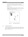
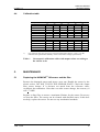
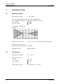
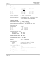
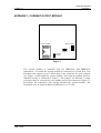
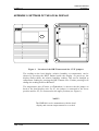
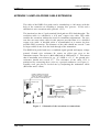
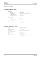
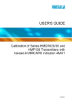
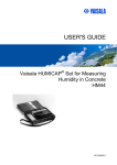
USER'S GUIDE ® Vaisala HUMICAP Humidity Transmitter Series HMP140A U175EN15 PUBLISHED BY Vaisala Oyj P.O. Box 26 FIN-00421 Helsinki Finland Phone (int.): +358 9 8949 1 Fax: +358 9 8949 2227 Visit our Internet pages at http://www.vaisala.com/ © Vaisala 2006 No part of this manual may be reproduced in any form or by any means, electronic or mechanical (including photocopying), nor may its contents be communicated to a third party without prior written permission of the copyright holder. The contents are subject to change without prior notice. Please observe that this manual does not create any legally binding obligations for Vaisala towards the customer or end user. All legally binding commitments and agreements are included exclusively in the applicable supply contract or Conditions of Sale. HMP140A SERIES Operating Manual U175en-1.5 Contents 1. PRODUCT DESCRIPTION ................................................................................................... 1 2. TO BE NOTED WHEN MEASURING HUMIDITY .................................................................. 2 3. INSTALLATION.................................................................................................................... 3 4. 5. 3.1 Selecting the place of installation .......................................................................... 3 3.2 Mounting .................................................................................................................. 3 3.2.1 Mounting the HMP141A............................................................................. 4 3.2.2 Mounting the HMP142A............................................................................. 4 3.2.3 Mounting the HMP143A............................................................................. 5 3.3 Electrical connections............................................................................................. 6 3.4 Connectors and potentiometers on the main PCB ................................................ 7 3.5 Selecting the outputs .............................................................................................. 7 3.6 Connection to an AC supply .................................................................................. 8 CALIBRATION ..................................................................................................................... 9 4.1 One-point humidity calibration ............................................................................... 9 4.2 Two-point humidity calibration............................................................................... 9 4.2.1 Two-point humidity calibration procedure................................................... 9 4.3 Temperature calibration ........................................................................................ 10 4.4 Calibration table .................................................................................................... 11 MAINTENANCE.................................................................................................................. 11 5.1 6. 7. Replacing the HUMICAP 180 sensor and the filter ............................................ 11 TECHNICAL DATA............................................................................................................. 12 6.1 Relative humidity................................................................................................... 12 6.2 Temperature........................................................................................................... 12 6.3 General................................................................................................................... 13 6.4 Electromagnetic compatibility .............................................................................. 14 6.4.1 Emissions................................................................................................ 14 6.4.2 Interference............................................................................................. 14 SPARE PARTS AND ACCESSORIES ................................................................................ 14 APPENDIX 1: CURRENT OUTPUT MODULE APPENDIX 2: SETTINGS OF THE LOCAL DISPLAY APPENDIX 3: HMP143A PROBE CABLE EXTENSION TECHNICAL DATA 1999-12-08 i HMP140A SERIES Operating Manual U175en-1.5 This page intentionally left blank. ii 1999-12-08 HMP140A SERIES Operating Manual U175en-1.5 1. PRODUCT DESCRIPTION The HMP140A series transmitters are reliable and easy to use instruments for the measurement of relative humidity and temperature. The series consists of three different types of transmitters to be chosen according to the requirements of the application: • HMP141A for wall installations • HMP142A for duct installations • HMP143A for installation in tight places The configuration can be chosen from various possibilities to meet the specific requirements of the customer. The transmitters can be ordered with a blank cover or a cover with a local display which outputs relative humidity and temperature readings. The reading to be displayed is chosen with a pushbutton on the cover and the desired temperature unit (Celsius or Fahrenheit) can be chosen with a jumper (see Appendix 2). All HMP140A transmitters measure relative humidity in the range of 0...100 %RH and temperature from -40 to +60 °C; the measurement is temperature compensated. The HMP140A transmitters have four different analogue outputs: 0...20 mA (4...20 mA), 0...1 V, 0...5 V and 0...10 V. The outputs are also scalable if necessary, e.g. 4...20 mA from 0...20 mA. The durable plastic cover provides IP65 protection from dust and sprayed water. The HMP140A transmitters are therefore suitable for most indoor and outdoor applications, including those with high humidities like indoor swimming pools etc. These versatile transmitters are also easy to install and to use. When necessary, they can be recalibrated on site with Vaisala’s HMI41 indicator equipped with an appropriate probe and optional calibration cable (19116ZZ). The HMP140A series transmitters incorporate the HUMICAP 180 sensor, the operation of which is based on the changes in its capacitance as the thin polymer film absorbs water molecules. The sensor is immune to most chemicals and has an excellent long-term stability. The temperature is measured with a Pt 1000 sensor. 1999-12-08 1 HMP140A SERIES Operating Manual 2. U175en-1.5 TO BE NOTED WHEN MEASURING HUMIDITY In the measurement of humidity and especially in calibration, it is essential that the temperature equilibrium is reached. Even a slight difference in the temperature between the measured object and the sensor causes an error. For example, at +20 °C (+ 68 °F) and 50 %RH, a temperature difference of +1 °C between the measured object and the sensor causes an error of +3 %RH. If relative humidity is 90 %RH, the error is about +5.4 %RH. The error is at its greatest when the temperature of the sensor differs from that of the surroundings and the humidity is high. A few degrees’ difference in temperature may cause water to condense on sensor surface. Efficient ventilation accelerates evaporation whereas in an unventilated space, it may take hours. The HUMICAP180 sensor returns to its normal functioning as soon as water has evaporated. Any contaminated water condensing on the sensor may shorten its life span and change the calibration. 10 9 8 dRH (%RH) 7 6 5 4 3 2 1 0 -40 -20 0 20 40 60 80 100 Temperature (°C) Figure 2.1 2 Measurement error at 100 %RH when the temperature difference between the ambient and the sensor is 1 °C 1999-12-08 HMP140A SERIES Operating Manual U175en-1.5 3. INSTALLATION 3.1 Selecting the place of installation Select a place that gives a true picture of the environment or process and is as clean as possible. Air should circulate freely around the sensor. A rapid air flow is recommended as it ensures the same temperature for the ambient air and the sensor head. Install the transmitter in a place where no cold or hot spot can develop. If the sensor head is installed in a duct or channel where the temperature is different from the ambient temperature, insulate the point of entry; this is particularly important if the transmitter is installed with the sensor head pointing downwards. Vertical installation of the HMP142A and HMP143A is not recommended; they should be mounted with the sensor head horizontally whenever possible. An uninsulated installation might lead to condensation on the sensor head and even if no condensation occurs, the resultant air flow may change the temperature near the sensor head and distort the readings. 3.2 Mounting The electronics of the HMP140A series can be disconnected for ease of installation and service. The housing can be conveniently installed and the electronics then consequently mounted. For service and maintenance purposes the electronics can be disconnected without disconnecting the cabling, and taken to an appropriate environment for necessary adjustments. 60 60 83.5 6.5 4.2 Figure 3 1999-12-08 Drilling dimensions (in mm) 3 HMP140A SERIES Operating Manual 3.2.1 U175en-1.5 Mounting the HMP141A The optimal installation of the HMP141A is with the sensor head pointing downwards. Upward mounting should be avoided due to internal heat transfer. 1. Mounting and wiring: cable feedthrough on the surface or in the connection box. 2. Mount the protection lid to the connection box. 3. Push the sensor head through the protection lid as in figure and connect the electronics housing to the connection box. Make sure that the pins at the bottom of the electronics housing are in contact with the screw terminal. 4. Fasten the four connecting screws of the electronics housing. 5. Place the sensor head into the protection lid. 6. Close the cover and fasten the two connection screws. 4 4 1 6 4 4 5 2 3 Figure 3.2.1 3.2.2 Mounting of the HMP141A Mounting the HMP142A The HMP142A transmitter should be mounted with the sensor head horizontally whenever possible. This way, any water that might condense on the tube cannot flow on to the sensors. When there is no alternative but to install the sensor head in the process vertically, the point of entry must be carefully insulated. 4 1999-12-08 HMP140A SERIES Operating Manual U175en-1.5 225 Ø 15 Figure 3.2.2 3.2.3 Ø 12 Dimensions of the HMP142A (in mm) Mounting the HMP143A The cable model HMP143A should also be mounted with the sensor head horizontally whenever possible. This model is provided with two plastic nuts and a gasket. Mount the nuts on the sensor head: disconnect the cable from the transmitter, insert the nuts and fasten them on the sensor head. Then reconnect the cable. A mounting flange is also available (see Fig. 3.2.3). The cable can also be extended up to 100 metres; see Appendix 3 for details. duct wall a plugged hole for reference measurements flange sealing M12x1 Ø 12 supporting bar 69 Figure 3.2.3 1999-12-08 Dimensions of the HMP143A probe (in mm) and installation in a channel with the help of flange (part no. HMP233FA) and supporting bar 5 HMP140A SERIES Operating Manual 3.3 U175en-1.5 Electrical connections The wiring can be done in either of the two ways shown in Figure 3.3. mounting on a juction box surface mount GND Tout SHIELD RHout Vs (OHFWULFDOFRQQHFWLRQV9RXWSXW (OHFWULFDOFRQQHFWLRQVP$RXWSXW *1' *1' 7 $ 9V RXW 6+,(/' 7RXW 9 9V 6+,(/' 5+ $ 5+RXW 9 RXW 9V 9V Figure 3.3 Outputs 0...20 mA (4...20 mA) min. 0...1 V 0...5 V 0...10 V 6 Electrical connections 20...35 VDC R (ohm) 12 + L VDC 50 9...35 VDC 15...35 VDC 20...35 VDC 17...24 VAC 9...24 VAC 12...24 VAC 16...24 VAC Current consumption 6...10 mA + output currents Electrical connections screw terminals for 0.5 - 1.5 mm2 wires (AWG 15...20), stranded wires recommended 1999-12-08 HMP140A SERIES Operating Manual U175en-1.5 3.4 Connectors and potentiometers on the main PCB DISPLAY CONNECTOR Test connector for factory use; leave the jumper as indicated here PROBE CONNECTOR VIO SHIELD GRN YEL BRN Tgain Toffset Test connector for one point calibration Spare jumpers X15 RHoffset Toutput selection Connectors for the current module RHgain X16 Figure 3.4 3.5 RHoutput selection Connectors and potentiometers on the main PCB Selecting the outputs The HMP140A series transmitters can be ordered with the desired output signals already selected. If the outputs are changed, the jumpers have to be moved to corresponding places (see Figure 3.5). For current outputs, see Appendix 1. Jumper changes may change the output < ±0.15 %FS within the chosen range; this usually does not give cause to recalibration. DISPLAY CONNECTOR PROBE CONNECTOR VIO SHIELD GRN YEL BRN Test connector for one point calibration Toutput selection Voltage Toutput selection 0-1V 0-5V RHoutput selection 0-10V Voltage RHoutput selection 0-10V 0-1V 0-5V Figure 3.5 1999-12-08 Jumper positions for voltage outputs 7 HMP140A SERIES Operating Manual 3.6 U175en-1.5 Connection to an AC supply The HMP140A transmitters can also be connected to an AC supply without an external rectifier. However, when two or more transmitters are connected to one 24 VAC transformer, a common loop is formed and there is an increased risk of a short-circuit. To avoid this, always use separate floating supply for each transmitter (see Figure 3.6 A). However, if several transmitters have to share one transformer, always connect the phase (∼) to + connector in each transmitter (see Figure 3.6 B). A) NO COMMON LOOP FORMED - RECOMMENDED supply voltage signal output supply voltage signal output HMP140 transmitter Controller HMP140 transmitter B) COMMON LOOP FORMED - NOT RECOMMENDED! signal output Controller shared common line signal output supply voltage supply voltage HMP140 transmitter HMP140 transmitter Figure 3.6 8 Connecting the transmitters to a 24 VAC supply 1999-12-08 HMP140A SERIES Operating Manual U175en-1.5 4. CALIBRATION 4.1 One-point humidity calibration The HMP140A series transmitters should be recalibrated approximately once a year. The interval depends on the operating conditions and the required accuracy. One-point calibration can be done with Vaisala’s portable HMI41 indicator equipped with an appropriate probe and optional calibration cable (19116ZZ). The cable is connected to a test connector either on the main component board of the HMP140A or, if a current output module is installed, on the module (see Figure 4.1). For more detailed instructions, see the operating manual of the calibration cable (U218en). DISPLAY CONNECTOR PROBE CONNECTOR VIO SHIELD GRN YEL BRN Test connector for one point calibration on the main PCB Test connector for one point calibration on the current module X15 X16 Current Module Figure 4.1 4.2 Location of the test connectors Two-point humidity calibration The calibration can also be done with the HMK11 or the HMK13B Calibrator, or the instrument can be sent to Vaisala or a Vaisala representative. 4.2.1 Two-point humidity calibration procedure • Leave the calibrator and the transmitter for at least 30 minutes in the same space so that their temperatures have time to equalize. • Place the probe into the calibration hole of the LiCl bottle in the humidity calibrator. • Wait for 10 minutes. 1999-12-08 9 HMP140A SERIES Operating Manual U175en-1.5 • Use the RH offset potentiometer (see Figure 4.2) to adjust the output signal to the value given in the calibration table (Chapter 4.4). • Place the probe into the calibration hole of the NaCl bottle in the calibrator. • Wait for 10 minutes. • Check that the reading corresponds within the desired accuracy to the reading given in the calibration table. If not, adjust the reading with the RH gain potentiometer (see Figure 4.2). • Check again the reading at the first point and adjust if necessary. DISPLAY CONNECTOR PROBE CONNECTOR Tgain Toffset RHoffset RHgain Figure 4.2 4.3 Calibration potentiometers Temperature calibration One point temperature calibration can be performed with the HMI41 equipped with an appropriate probe and optional calibration cable if the accuracy of +0.5 °C is sufficient. For further details, see the operating manual of the HMI41 and calibration option. 10 1999-12-08 HMP140A SERIES Operating Manual U175en-1.5 4.4 Calibration table Temperature *) LiCl 4...20 mA 0...20 mA 0...1 V 0...5 V 0...10 V °C °F %RH mA mA V V V 15 59 *) 20 68 11.3 5.81 2.26 0.113 0.565 1.13 25 77 11.3 5.81 2.26 0.113 0.565 1.13 30 86 11.3 5.81 2.26 0.113 0.565 1.13 35 95 11.3 5.81 2.26 0.113 0.565 1.13 NaCl 4...20 mA 0...20 mA 0...1 V 0...5 V 0...10 V %RH mA mA V V V 75.6 16.10 15.12 0.756 3.780 7.56 75.5 16.08 15.10 0.755 3.775 7.55 75.3 16.05 15.06 0.753 3.765 7.53 75.1 16.02 15.02 0.751 3.755 7.51 74.9 15.98 14.98 0.749 3.745 7.49 LiCl solution must not be used or stored in temperatures below +18 °C (+64 °F); otherwise the equilibrium humidity of the salt solution changes permanently Table 1 Greenspan’s calibration table with output values according to the chosen scale 5. MAINTENANCE 5.1 Replacing the HUMICAP180 sensor and the filter Remove the damaged sensor and insert a new one. Handle the sensor by the plastic socket. DO NOT TOUCH THE SENSOR PLATE. Check the output after sensor change. If it deviates too much from the reference value, recalibrate the transmitter. Note that even after sensor change, the accuracy is still +7 %RH. Replace a dirty filter to ensure a maximum lifetime for the sensor. Do not try to clean the filter. The sensor can be cleaned with distilled water; if this does not help, replace the sensor. Do not use any mechanical methods. 1999-12-08 11 HMP140A SERIES Operating Manual U175en-1.5 6. TECHNICAL DATA 6.1 Relative humidity Measurement range 0...100 %RH Accuracy (including non-linearity and repeatibility) when calibrated against salt solutions (ASTM E104-85): 0...90 %RH +2 %RH 90...100 %RH +3 %RH Temperature dependence: dRH (%RH) 2 1.5 1 0.5 0 -0.5 -1 -1.5 -2 -20 -10 0 10 Response time (90%) 20 30 40 50 60 T (°C) 15 s at +20 °C in still air (with sintered filter) Maximum error between the display and the outputs 0.2 %RH Humidity sensor 6.2 12 HUMICAP180 Temperature Measurement range -20...+60 °C Typical accuracy at: +20 °C -10...+40 °C -20...+60 °C +0.2 °C +0.3 °C +0.4 °C Temperature sensor Pt 1000 IEC 751 Class B 1999-12-08 HMP140A SERIES Operating Manual U175en-1.5 6.3 General Power supply current outputs: min. 20...35 VDC 12 + RL(ohm) 17...24 VAC 50 0...1 V 0...5 V 0...10 V 9...35 VDC 15...35 VDC 20...35 VDC 9...24 VAC 12...24 VAC 16...24 VAC Current consumption 6...10 mA + output currents Electrical connections screw terminals for 0.5 - 1.5 mm2 wires (AWG 15...20), stranded wires recommended Alternative analogue output signals (scalable) 0...20 mA (4...20 mA) 0...1 V, 0...5 V, 0...10 V NOTE! Output scales correspond to 0…100 %RH and -40…+60°C. External loads for current outputs 0...1 V 0...5 V 0...10 V < 500 Ω > 1 kΩ (to ground) > 5 kΩ (to ground) >10 kΩ (to ground) Operating temperature range for electronics -20...+60 °C with display option 0...+50 °C Storage temperature range -40...+80 °C Operating humidity range 0...100 %RH Bushing for ∅ 7...10 mm cables Sensor protection standard option membrane filter, part no. 17039HM plastic grid, part no. 17038 Cable length of HMP143A standard 2.5 m maximum 100 m (user extendable, see Appendix 3) 1999-12-08 Housing material ABS plastic Housing classification IP65 (NEMA 4) 13 HMP140A SERIES Operating Manual 6.4 Electromagnetic compatibility 6.4.1 Emissions Test: Setup according to: Radiated interference EN55022 6.4.2 7. U175en-1.5 (class B) Interference Test: Setup according to: Performance: Electrostatic discharge IEC 801-2 criteria B RF-radiated fields (allowed temporary effect ±1 °C in temperature) IEC 801-3 criteria A Electrical fast transients IEC 801-4 criteria B SPARE PARTS AND ACCESSORIES Order code HMP233FA 19326 1535 17039HM 17038 HUMICAP®180 Description mounting flange for the HMP143A junction box for the HMP143A cable extension (seeApp.3) extension cable for the HMP143A (see Appendix 3) membrane filter plastic grid humidity sensor GUARANTEE Vaisala issues a guarantee for the material and workmanship of this product under normal operating conditions for one (1) year from the date of delivery. 14 1999-12-08 U175en-1.5 HMP140A SERIES Operating Manual Exceptional operating conditions, damage due to careless handling and misapplication will void the guarantee. 1999-12-08 15 HMP140A SERIES Appendix 1 U175en-1.5 APPENDIX 1: CURRENT OUTPUT MODULE Current module X15 Spare jumpers T output selection X16 RH output selection Figure 1 The current module is available only for HMP142A and HMP143A transmitters. To install the current module to connectors X15 and X16, first disconnect the jumpers (4 pcs). Insert them to the connector for spare jumpers (see Figure 1) and install the current module. Note that the module must be installed exactly as indicated in Figure 1. The jumpers for RH and T output selections must be connected in two middle pins of the connectors (Figure 1). Recalibrate the transmitter after having installed the current module. The maximum error in output without recalibration is ± 0.5 %FS. 1999-12-08 1 HMP140A SERIES Appendix 2 U175en-1.5 APPENDIX 2: SETTINGS OF THE LOCAL DISPLAY °F RH/T °C Figure 1 Location of the RH/T button and the °C/°F jumpers The reading on the local display (relative humidity or temperature) can be chosen by pressing the RH/T button beside the display. At power-up, the display always shows the relative humidity reading. This can be changed to temperature reading by pressing the RH/T button once. Further pressings will change the reading between RH and T. The temperature unit (°Celsius or °Fahrenheit) is chosen with the jumper on back of the local display unit. For °C, the jumper is connected to the lower position and for °F, it is connected to the upper position (see Figure 1). NOTE! The HMP140A series transmitters with the local display and current output cannot be re-scaled. 1999-12-08 1 HMI41 Appendix 2 2 HMI41-Uxxxen-1.1 1999-12-08 HMP140A SERIES Appendix 3 U175en-1.5 APPENDIX 3: HMP143A PROBE CABLE EXTENSION The cable of the HMP143A probe can be extended up to 100 metres with the help of the extension set including a junction box (part no. 19326) and a shielded six wire extension cable (part no. 1535). The junction box has a 5-pole terminal block and two PG9 lead-throughs. The extension cable is a shielded 6 x 0.22 mm 2 copper wire cable. This cable enables the extension without the need for transmitter adjustments. The user can also use some other cable for this purpose provided that it is a shielded copper wire cable. A shielded cable is recommended as it ensures the best possible EMC protection. The diameter of the cable should not exceed 7 mm as larger cables do not fit to the lead-through of the transmitter. The HMP143A probe head uses a combined signal ground and supply voltage ground. Ground wire resistance Rc causes an offset type error to the transmitter output. The error is -0.11 x Rc both in %RH and in °C. This means that if maximum error allowed is e.g. -0.3 %RH or -0.3 °C, the ground wire resistance should not exceed 2.7Ω. The resistance of the cable 1535 is minimized by connecting three wires as a ground conductor (see Figure 1). Possible error can also be leveled out by readjusting the transmitter offset (RH offset and T offset). PROBE CONNECTOR ON THE HMP143 PCB; THE COLOURS SHOW THE DIRECT CONNECTION OF THE HMP143 PROBE HEAD PROBE CONNECTOR VIO SHIELD GRN YEL BRN HMP143 PROBE CONNECTOR EXTENSION CABLE CABLE SHIELD JUNCTION BOX BLU GREY YEL BLK HMP143 CABLES VIO SHIELD GRN (ground) YEL BRN THREE WIRES CONNECTED TOGETHER (WHT, GRN, RED) Figure 1 1999-12-08 Schematic of the extension set connections 1 HMP140A Appendix 3 U175en-1.5 TECHNICAL DATA Junction box (part no. 19326) Housing: material dimensions classification temperature range ABS plastic 65 x 50 x 35 mm (l x w x h) IP 65 -40...+80 °C Lead-throughs: size cable diameter housing classification PG 9 4...7 mm IP 68 Terminal block: max. wire area 1.5 mm2 Extension cable (part no. 1535) Type Wire resistance Covering Cross-sectional area of the wires Cover Temperature range Wire colours 2 PFSK 6 x 0.22 mm2 80 Ω / km braided, tinned copper wire 0.22 mm2 PVC, light grey -30...+70 °C red, blue, green, yellow, white, black (DEF-STAN 61-12) 1999-12-08 www.vaisala.com