1
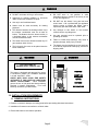
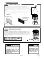
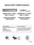
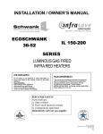
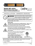
INSTALLATION / OWNER’S MANUAL
SCH-90
&
IC-90
SERIES
CONSTRUCTION
GAS FIRED
INFRA RED HEATERS
CAUTION: Read all instructions before use Retain this
manual for further reference.
Page 1
GP-MCH9-BX-10C
SCH-90 / IC-90 Manual
R.D: Aug 2006
RL:10C
KH
NOTICE:
The Manufacturer reserves the right to make changes to equipment and specifications without obligation or notification.
This publication, or parts thereof, may not be reproduced in
any form, without prior written consent from The Manufacturer.
Unauthorized use or distribution of this publication is strictly
prohibited.
Schwank Group
5285 Bradco Boulevard
Mississauga, Ontario,
L4W 2A6
Phone: (905) 712-4766
Fax: (905) 712-8336
1-866-361-0417
InfraSave
Mississauga, Ontario,
Waynesboro,Georgia,
Phone: 1-866-INFRASV (463-7278)
Fax: 1-866-724-9265
http://www.infrasave.com
e-mail: [email protected]
PO Box 988, 2 Schwank Way
Waynesboro, Georgia,
USA 30830
Phone: (706) 554-6191
Fax: (706) 554 9390
1-877-446-3727
e-mail: [email protected]
http://www.schwankgroup.com
Page 2
GP-MCH9-BX-10C
SCH-90 / IC-90 Manual
R.D: Aug 2006
RL:10C
KH
TABLE OF CONTENTS
— INFORMATION AND SAFETY LABELS
4
1.0
6
INSTALLATION REQUIREMENTS
1.1
1.2
1.3
1.4
1.5
1.6
1.7
1.8
GENERAL INSTRUCTIONS
GAS SUPPLY LINE/GAS PRESSURE
VENTILATION REQUIREMENTS
CLEARANCES TO COMBUSTIBLES
MOUNTING INSTRUCTIONS
LIGHTING/SHUTDOWN INSTRUCTIONS
LIGHTING/SHUTDOWN INSTRUCTIONS
THERMOSTATIC CONTROL
6
7
7
7
8
9
9
10
2.0 MAINTENANCE
10
3.0 REPLACEMENT PARTS
3.1 SCH-90 / IC-90-N/L
3.2 SCH-90-M / IC-90-M-N/L
12
12
14
4.0 WARRANTY
16
TECHNICAL SPECIFICATIONS
Input (BTU) - Normal Altitude:
- High Altitude:
NG
90,000
81,000
LP
87,500
79,545
Height (inches):
36”
Width (inches):
24”
Ignition controls:
standing
pilot
Thermostat:
finger
touch
control
Tip-over switch:
35º
Gas inlet:
Clearances to:
Combustibles
24” (top)
48” (side)
Minimum gas:
6.3” (NG)
Pressure (W.C.) 11.3” (LP)
No electric power required.
Page 3
NG-1/2” LP-3/8”
Also available in 200,000 BTU
GP-MCH9-BX-10C
SCH-90 / IC-90 Manual
R.D: Aug 2006
RL:10C
KH
Page 4
GP-MCH9-BX-10C
SCH-90 / IC-90 Manual
R.D: Aug 2006
RL:10C
KH
For Your Information and Safety …
Please read the following warning labels.
WARNING
WARNING
Failure to comply with the precautions and
instructions provided with this heater can result in
death, serious bodily injury and property loss,
damage from hazards of fire explosion, burn,
asphyxiation / carbon monoxide poisoning.
Only persons who can understand and follow the
instructions should use this heater. Service of this
heater should be performed by a qualified service
person only.
If you need assistance, or heater information such
as an instruction manual, labels, etc. contact your
local dealer.
FOR YOUR SAFETY
•
DO NOT store or use gasoline or other
flammable vapors and liquids in the vicinity of
this or any other appliance.
WHAT TO DO IF YOU SMELL GAS:
•
•
•
•
DO NOT try to light any appliance.
DO NOT touch any electrical equipment.
DO NOT use any telephone equipment in the
immediate area.
Immediately call your gas supplier or call the fire
department.
WARNING
Improper assembly, adjustment, alteration, service or maintenance can cause injury, property damage, or
death. For assistance or additional information, refer to this manual, or consult a qualified service agency, or
the gas supplier.
WARNING
Fire, burn, inhalation, and explosion hazard. Keep solid combustibles, such as building materials, paper or
cardboard, a safe distance away from the heater as recommended by the instructions. Never use the heater in
spaces that do or may contain volatile or airborne combustibles, or products such as gasoline, solvents, paint
thinner, dust particles or unknown chemicals.
Page 5
GP-MCH9-BX-10C
SCH-90 / IC-90 Manual
R.D: Aug 2006
RL:10C
KH
WARNING
•
•
•
•
•
•
•
•
DO NOT use heater in living or office areas.
Approved for heating buildings or structures
under construction, alteration or repair.
Use only in well ventilated areas.
Heater must be used exclusively for heating
purposes.
The distance between the heating surface top to
the nearest combustible must be at least 24
inches. The distance from the burner surface, in
a horizontal plane, to the nearest combustible
must be at least 48 inches.
The heater must not be directed towards any LP
gas container within 10 feet.
The fuel supply line must not be placed near the
burner heat zone.
WARNING
•
•
•
•
•
DO NOT store or use gasoline or other
flammable vapors or liquids in the vicinity of this
or any other appliance.
DO NOT use this heater if any part has been
under water. Call a professional gas appliance
service person to inspect the heater, and to
replace any part which has been under water.
Any changes to this heater or the heater’s
controls can be very dangerous.
Any part removed must be replaced prior to
operating the heater.
Failure to follow these warnings may result in
property damage, bodily injury or death.
The heater must be installed in such a way that it
is not directly exposed to water spray, rain and or
dripping water.
WARNING
NOT FOR HOME OR
RECREATIONAL VEHICLE USE
This heater is designed and approved for use as
a construction heater per Canadian Standard
2.14 and Ansi Z83.7 –2000.
CHECK WITH YOUR LOCAL FIRE SAFETY
AUTHORITY IF YOU HAVE ANY QUESTIONS
ABOUT APPLICATIONS.
Other standards
govern the use of fuel gases and heat producing
products in specific applications. Your local
authority can advise you about these.
HEATER
MUST BE
LEVEL
BEFORE
OPERATING
1.0 INSTALLATION REQUIREMENTS
1.1 GENERAL INSTRUCTIONS
1. Examine contents for damage or missing parts before proceeding with these instructions.
2. Installation of heaters must conform to all local codes.
3. Ensure that heater is level before operation.
Page 6
GP-MCH9-BX-10C
SCH-90 / IC-90 Manual
R.D: Aug 2006
RL:10C
KH
1.2 GAS SUPPLY & PRESSURE INFORMATION
All piping and hose must be installed according to local code, and must be of adequate size and construction.
Natural gas models must have the supply line limited to 14 inches (maximum) water column.
If the line pressure will go above 14 inches water column at any time, a separate regulator must be used. The
minimum supply line pressure at the inlet to the heater regulator must in no case be lower than 6.3 inches of water
column.
Note: The regulator is an internal component of the heater and maintains the heater’s manifold pressure; natural
gas is 5.5 inches water column, and LP gas is 10.5 inches water column.
Heaters equipped for LP gas operations must have a minimum supply line pressure 11.3 inches of water column
at the heater. Maximum line pressure is 1/2 PSI (14 inches water column).
WARNING
1. Minimum hose length – Canada fifteen feet (15’) — USA ten feet (10’)
feet (50’) (3/4” inside diameter)
Maximum hose length - Fifty
2. LP Gas Cylinder must be located a minimum ten feet away from heater while heater is in operation.
3. After assembly and every time the heater is attached to a new gas cylinder or gas meter, check for leaks
with a soap solution or leak tester on all gas lines and connections. Failure to do so may result in property
damage, bodily injury or death. DO NOT USE AN OPEN FLAME.
If high pressure is used to check for leaks, do not subject this heater’s controls to excessive pressure.
1.3 VENTILATION REQUIREMENTS
It has been determined that CO2 levels should not exceed 5000 PPM (parts per million) and CO should not exceed 35 PPM for an eight hour continuous exposure.
Combustion of gas fuel requires air. Each SCH-90 heater requires 90 sq.in. of opening for combustion air. (ex.:
9” x 10” window opening)
To maintain the carbon dioxide content in the air at or below the concentration mentioned above, the number of air
changes are listed below depending on the size of the space being heated:
TABLE 1
1.4 CLEARANCES TO COMBUSTIBLES
Required room air changes per hour
Room Volume cu.ft.
No. of air changes /
5000
7,500
5
3
10,000
2.5
15,000
20,000
25,000
50,000
1.5
1.25
1
.5
Page 7
TABLE 2
MODEL
SIDE
( From Radiant Surface)
TOP
(From Radiant
Surface)
SCH-90 / IC-90-N
SCH-90 / IC-90-L
SCH-90 / IC-90-M-N
SCH-90 / IC-90-M-L
48”
48”
48”
48”
24”
24”
24”
24”
GP-MCH9-BX-10C
SCH-90 / IC-90 Manual
R.D: Aug 2006
RL:10C
KH
FIGURE
FIGURE 1:
1: SUSPENDED
SUSPENDEDFROM
FROMCEILING
CEILHeater may be suspended from ceiling using chain and mounting hardware.
When hanging from joists / beams the 24” clearance to combustibles must be
maintained, and measured from the bottom underside of the joist or beam as per
drawing, and NOT from the suspension anchoring point of the chain. (See Table
2 page 6)
The construction heater is CSA International approved to be suspended as per
these instructions and using the approved manufacturer's supplied suspension
hardware. (optional part #JH-0910-xx)
Note: Suspending heaters is not allowed in some jurisdictions, check your
local codes.
24” (MINIMUM)
1.5 MOUNTING INSTRUCTIONS
JOIST NO LESS THAN 2” X 6”
3/8” DIAMETER EYEHOOK DRIVE
THREADED PORTION FULLY
INTO JOIST THICKNESS.
3/16” DRILL BIT
GAS LINE CONNECTION
2” (MINIMUM)
FIGURE 2: FREE STANDING FLOOR MOUNT
A steel rod, non-combustible base is an integral part of this heater. The
heater may safely be placed directly on a combustible surface. Always
maintain minimum distance to combustibles as shown in Table 2. Gas
supply hose/piping must lay over the top of bottom rim of heater as
shown here.
NOTE: Heater is equipped with a tilt safety
feature. Heater will automatically shut down
when it is tilted over 900 degrees
WARNING
GAS SUPPLY LINE
CAUTION
Surface of heater will be hot to the
touch. Take proper precautions.
If the heater location must be
changed, allow the heater to cool a
full 15 minutes before attempting to
handle the heater.
On floor mounted units,
the Gas supply line must
lay above the bottom rim
of heater. See Figure 2.
Page 8
GP-MCH9-BX-10C
SCH-90 / IC-90 Manual
R.D: Aug 2006
RL:10C
KH
1.6 LIGHTING / SHUTDOWN INSTRUCTIONS
1. Pre-purge gas line prior to lighting.
2. Place knob in the OFF position, rotate knob 1 notch, or “click” counter-clockwise.
Depress and
hold the control knob. Light pilot through porthole. Release knob after sixty seconds. Pilot burns,
main burner is off.
3. Turn knob counter-clockwise
to ignite main burner. Adjust knob to desired heat setting.
4. If burner does not light, turn knob completely clockwise .
knob. Wait five minutes and repeat step two.
Leave in off position without pressing
5. For complete shutdown of burner and pilot, turn knob completely clockwise,
then depress knob.
FIGURE 3
PILOT / VEILLEUSE
PLUS CHAUD
/ WARMER
OFF / ARRÊT
Thermostatic Control Knob
note: this is an Instructional Sticker Only
1.7 THERMOSTATIC CONTROL
Multifunctional gas control with snap acting thermostat, thermo-electric flame-failure safety device, and
a manual ON/OFF function. Thermostat range is 50ºF - 100ºF.
MAINTENANCE
See page 9.
Page 9
GP-MCH9-BX-10C
SCH-90 / IC-90 Manual
R.D: Aug 2006
RL:10C
KH
1.8 LIGHTING / SHUTDOWN INSTRUCTIONS
1. Pre-purge gas line prior to lighting.
2. Turn the knob counterclockwise to PILOT position, push the knob down and hold in position. The
pilot valve opens and allows gas to flow to the pilot burner.
3. While holding the knob down, light the pilot burner, continue to hold knob down until a strong flame
is present, continue holding for an additional 60 seconds.
4. Release the knob. The shaft moves upward and engages the safety valve level that opens the
safety valve.
5. Turn the knob counterclockwise to the ON position. On a call-for-heat the main valve opens and
the main burner ignites.
6. To shut off the system, turn the knob clockwise to the OFF position. This action closes the main
gas and safety valves. However the power unit must drop out before the lighting sequence can
begin again. The valve drops out within three minutes.
Thermostat range is 50o F
to 100o F. Turn Thermostat
clockwise to increase the
room temperature.
Turn counter clockwise all
the way to shut off, call for
heat pilot is on for standby.
2.0 MAINTENANCE
This heater should be cleaned at least once annually with a dry cloth. This heater should be inspected
before each use and at least once annually by a qualified service person.
The gas hose assembly shall be visually inspected prior to each use of the heater. If damage is evident
it must be replaced prior to the heater being placed into operation. For replacement part information,
see pages 12 & 14.
LP model heaters should use a standard LP gas cylinder. Cylinder must be located a minimum of 10
feet away from heater while heater is in operation. The cylinder must be provided with a system for vapor withdrawal. The gas must be turned off at the LP gas supply cylinder when the heater is not in use.
The connection of the gas cylinder should be made with the #510 connector which tightens by turning
the threads to the left. To disconnect the fitting make sure the gas is turned off, and loosen threads by
turning them to the right. When heater is to be stored indoors the connection between the LP gas cylinder and the heater must be disconnected.
Keep appliance area free and clear from combustible materials, gasoline and other flammable vapors
and liquids. Ensure that the flow of combustion and ventilation air is free from all obstructions.
Page 10
GP-MCH9-BX-10C
SCH-90 / IC-90 Manual
R.D: Aug 2006
RL:10C
KH
Replace filter at least:
- once every 2 weeks
FILTER RETAINER
- minimum once a day when sanding drywall
- each time when connecting heater at different location
FILTER RETAINER
& FILTER
* Clean burner screen with each filter change;
( see next window )
FILTER
Filter replacement:
- Shut off gas supply
- Grasp filter retainer and pull together at retainer grips
- Free filter retainer
- Remove and discard filter
- Replace with a new filter
- Reinstall filter retainer, complete with filter
Clearing Burner Screen:
- Make sure gas supply is off
- Use compressed air If air is not available on the site, aerosol can is
available:
- Insert air nozzle through the pilot lighting hole at side of mantle base
- Direct at flame retaining screen, and blow out any accumulated dust
- Re-open gas supply
- Re-light pilot, and continue using the construction heater as before.
COMPRESSED AIR
Page 11
GP-MCH9-BX-10C
SCH-90 / IC-90 Manual
R.D: Aug 2006
RL:10C
KH
3.0 REPLACEMENT PARTS
3.1 REPLACEMENT PARTS FOR SCH 90-N/L / IC-90-N/L
TABLE 3: REPLACEMENT PARTS LIST
(REFERENCE PAGE 9)
ITEM NO.
PART NAME
SCH-90-N
SCH-90-L
1
SHROUD
JH-0613-XX
JH-0613-XX
WIRE GUARD
JH-0610-XX
JH-0610-XX
UPPER RING PORTION OF GUARD Only
JH-0610-TP
JH-0610-TP
LOWER LEGS PORTION OF GUARD Only
JH-0610-BM
JH-0610-BM
2
3
MANTLE
JH-0433-XX
JH-0433-XX
4
VENTURI ASSEMBLY
JH-0615-XX
JH-0615-XX
5
BURNER GASKET
JH– 0437-FF
JH-0437-FF
6
FLAME SCREEN RETAINER RING
JH-0439-XX
JH-0439-XX
7
FLAME SCREEN
JH-0441-XX
JH-0441-XX
8
THERMOSTATIC GAS VALVE
JH-0412-NG
JH-0412-LP
9
MAIN ORIFICE
JH-0418-NG
JH-0418-XX
10
PILOT BURNER (NOT SHOWN
JH-0406-XX
JH-0406-XX
11
PILOT ORIFICE HONEYWELL (NOT SHOWN)
JH-0407-NG
JH-0407-LP
12
PILOT TUBE
JH-0463-XX
JH-0463-XX
13
THERMOCOUPLE
JH-0403-XX
JH-0403-XX
14
BLACK WIRE ASSEMBLY (NOT SHOWN)
JH-0465-XX
JH-0465-XX
15
SAFETY TIP SWITCH
JH-0405-XX
JH-0405-XX
16
1/2” VALVE INLET ELBOW (3/8”AVAILABLE)
JH-0640-XX
JH-0641-XX
17
QUICK CONNECT
JH-0601-ML
JH-0591-ML
18
CONTROL KNOB
JH-0412-TK
JH-0412-TK
19
REGULATOR ASSEMBLY (NOT SHOWN)
—
JH-0903-RG
20
HOSE ASSEMBLY—(NOT SHOWN)
JH-0902-XX
JH-0902-LP
21
E.C.O. ADAPTOR—(NOT SHOWN)
JH-0401-XX
JH-0401-XX
22
SPRING
JH-0412-SP
JH-0412-SP
23
8” RETAINER GRIPS (16” AVAILABLE)
JH-0936-XX
JH-0936-XX
24
FILTER RETAINER
JH-0935-XX
JH-0935-XX
25
FILTER
JH-0933-XX
JH-0933-XX
Page 12
GP-MCH9-BX-10C
SCH-90 / IC-90 Manual
R.D: Aug 2006
RL:10C
KH
FIGURE 4: REPLACEMENT PARTS DIAGRAM FOR SCH 90-N/L / IC-90-N/L
2
3
24
1
25
15
23
6
5
22
7
8
18
17
16
13
12
4
9
Page 13
GP-MCH9-BX-10C
SCH-90 / IC-90 Manual
R.D: Aug 2006
RL:10C
KH
3.1 REPLACEMENT PARTS FOR SCH 90-M- N/L / IC-90-M-N/L
TABLE 3: REPLACEMENT PARTS LIST
(REFERENCE PAGE 9)
ITEM NO.
PART NAME
SCH-90-N
SCH-90-L
1
SHROUD
JH-0613-XX
JH-0613-XX
WIRE GUARD
JH-0610-XX
JH-0610-XX
UPPER RING PORTION OF GUARD Only
JH-0610-TP
JH-0610-TP
LOWER LEGS PORTION OF GUARD Only
JH-0610-BM
JH-0610-BM
2
3
MANTLE
JH-0433-XX
JH-0433-XX
4
VENTURI ASSEMBLY
JH-0615-XX
JH-0615-XX
5
BURNER GASKET
JH– 0437-FF
JH-0437-FF
6
FLAME SCREEN RETAINER RING
JH-0439-XX
JH-0439-XX
7
FLAME SCREEN
JH-0441-XX
JH-0441-XX
8
MILLIVOLT GAS VALVE
JH-0414-NG
JH-0414-LP
9
MAIN ORIFICE
JH-0418-NG
JH-0418-XX
10
PILOT BURNER (NOT SHOWN)
JH-0406-XX
JH-0406-XX
11
PILOT ORIFICE HONEYWELL (NOT SHOWN)
JH-0407-NG
JH-0407-LP
12
PILOT TUBE
JH-0463-XX
JH-0463-XX
13
MILLIVOLT GENERATOR - POWERPILE
JH-0504-XX
JH-0504-XX
14
BLACK WIRE ASSEMBLY (NOT SHOWN)
JH-0465-XX
JH-0465-XX
15
THERMOSTAT ASSEMBLY
JH-0414-TS
JH-0414-TS
16
VALVE INLET
JH-0640-XX
JH-0641-XX
17
QUICK CONNECT
JH-0601-ML
HJ-0591-ML
18
8” RETAINER GRIPS (16” AVAILABLE)
JH-0936-XX
JH-0936-XX
19
REGULATOR ASSEMBLY (NOT SHOWN)
—
JH-0903-RG
20
HOSE ASSEMBLY—(NOT SHOWN)
JH-0902-XX
JH-0902-LP
21
FILTER RETAINER
JH-0935-XX
JH-0935-XX
22
FILTER
JH-0933-XX
JH-0933-XX
Page 14
GP-MCH9-BX-10C
SCH-90 / IC-90 Manual
R.D: Aug 2006
RL:10C
KH
FIGURE 5: REPLACEMENT PARTS DIAGRAM FOR SCH 90-M- N/L / IC-90-M-N/L
2
3
21
22
1
15
18
8
6
5
17
13
7
16
4
12
9
Page 15
GP-MCH9-BX-10C
SCH-90 / IC-90 Manual
R.D: Aug 2006
RL:10C
KH
Page 16
GP-MCH9-BX-10C
SCH-90 / IC-90 Manual
R.D: Aug 2006
RL:10C
KH
LIMITED WARRANTY CERTIFICATE
FOR GAS-FIRED INFRA-RED CONSTRUCTION HEATER : SCH / IC SERIES
The Manufacturer warrants that this product is free from defects in material or workmanship under normal use and service subject to
the terms of this document.
ONE YEAR WARRANTY
Subject to the conditions and limitations stated herein, during the term of this limited warranty, we will supply any component part
(at our option a new or repaired component part) of the heater, as defined below, excluding any labor, which the Manufacturer’s examination determines to be defective in workmanship or material for a period of one year (1 year) from the date of installation,
unless otherwise specified below. This warranty applies to the heater’s original owner, and subsequent transferees and only if the
unit is installed and operated in accordance with the printed instructions accompanying the unit and in compliance with all applicable installation, building codes and good trade practices.
BURNER AND MANTLE - ONE YEAR WARRANTY
The manufacturer warrants the burner and ceramic tile for a period of one year. (1 year)
WHAT IS NOT COVERED
The Manufacturer shall not be responsible for any expenses, including service, labor, diagnosis, analysis, material or transportation
charges incurred during removal or reinstallation of this product, or any of its components or parts. All labor or service charges shall
be paid by the owner. This warranty does not cover heating products improperly installed, misused, exposed to or damaged by negligence, accident, corrosive or contaminating atmosphere, water (except STW-JZ / IW), excessive thermal shock, impact, abrasion,
normal wear due to use, alteration or operation contrary to the owner’s manual or if the serial number has been altered, defaced or
removed. This warranty shall not apply if the input to the heating product exceeds by more than 2% of the rated input on the rating
plate. The Manufacturer shall not be liable for any default or delay in performance by its warranty caused by any contingency beyond its control, including war, government restrictions, or restraints, strikes, fire, flood, acts of God, or short or reduced supply of
raw materials or products.
WARRANTY PROCEDURE
To establish the installation date for any purpose under this Limited Warranty, you must retain the original records that can establish
the installation date of your unit. If you do not provide such documents, the start date of the term of this Limited Warranty will be
based upon the date of unit manufacture, plus thirty (30) days. Failure to maintain the equipment through regular annual service
maintenance by a qualified service technician shall void the warranty.
LIMITATIONS AND EXCLUSIONS
This document contains all warranties made by the Manufacturer and may not be varied, altered or extended by any person. There
are no promises, or agreements extending from the Manufacture other than the statements contained herein. THIS WARRANTY IS
IN LIEU OF ALL WARRANTIES EXPRESSED OR IMPLIED, TO THE EXTENT AUTHORIZED BY THE LAWS OF THE
JURISDICTION, INCLUDING SPECIFICALLY THE WARRANTIES OR MERCHANTIBILITY OF FITNESS FOR A PARTICULAR PURPOSE.
It is understood and agreed that the Manufacturer’s obligation hereunder is limited to repairing or replacing parts determined to be
defective as stated above. In no event shall the Manufacturer be responsible for any alleged personal injuries or other special, incidental or consequential damages. As to property damages, contract, tort or other claim the Manufacturer’s responsibility shall not
exceed the purchase priced paid for the product.
All replacement parts will be warranted for the unused portion of the warranty coverage period remaining on the applicable unit.
Some Authorities do not allow certain warranty exclusions or limitations on how long a warranty lasts or the exclusions or limitations of incidental or consequential damages. In such cases, the above limitations or exclusions may not apply to you and are not
intended to do so where prohibited by law. This warranty gives you specific legal rights. You may also have other rights which
vary by each jurisdiction.
5285 BRADCO BLVD. MISSISSAUGA, ON, L4W 2A6
2 SCHWANK WAY, WAYNESBORO, GEORGIA. 30830-8336
SCHWANK
INFRASAVE
Ph: 905-712-4766 Fax: 905-712-8336
Ph: 1-866– INFRASV (463 7278) Fax: 1-866-724 –9265
Page 17
GP-DCHX-BX-03B
SCH / IC WARRANTY
March 2006
RL: 3B
KH
GP-MCH9-BX-10C
SCH-90 / IC-90 Manual
R.D: Aug 2006
RL:10C
KH