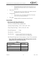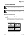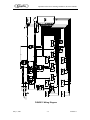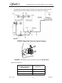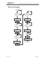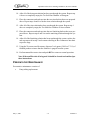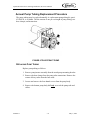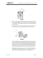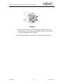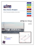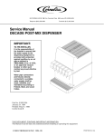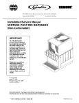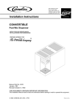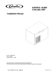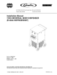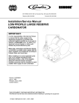
1
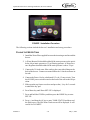
Lipton Brewed Iced Tea
Double Valve Dispenser
Training, Installation, & Service Manual
Safety & Specifications
Installation
Service
Training
Part No. 630460171
©2001-2002, IMI Cornelius, Inc.
May 7, 2002
Revision B
Lipton Brewed Iced Tea Training, Installation, & Service Manual
630460171
ii
May 7, 2002
Lipton Brewed Iced Tea Training, Installation, & Service Manual
Lipton Iced Tea Brewer
Training, Installation, & Service Manual
The products, technical information, and instructions contained in this manual are subject
to change without notice. These instructions are neither intended to cover all details or
variations of the equipment, nor to provide for every possible contingency in the installation, operation, or maintenance of this equipment. This manual supposes that the person(s)
working on the equipment are trained and skilled in working with electrical, plumbing,
pneumatic, and mechanical equipment. In addition to the information this manual provides, Cornelius expects proper installation that includes taking appropriate safety precautions as well as adhering and meeting all local safety and construction requirements.
To inquire about current revisions of this and other documentation, or for assistance please contact:
Fresh Brewed Service:
------------ 1-866-LiptonT
------------1-866-547-8668
NGB.
505 Cleveland Street
Blairsville, GA.
30512
U.S.A.
Email:
[email protected]
Trademarks and copyrights:
Aurora, Cornelius, Decade, Hydro Boost, Sitco, Spirit, UF-1, Vanguard, Venture, and Vista are registered
trademarks of IMI Cornelius.
Optifill trademark is pending.
LITB Dispenser US and Foreign Patents pending
This document contains proprietary information and it may not be
reproduced in any way without permission from Cornelius.
Printed in U.S.A.
Copyright © 2001-02, All Rights Reserved, IMI Cornelius Inc.
May 7, 2002
iii
630460171
Lipton Brewed Iced Tea Training, Installation, & Service Manual
630460171
iv
May 7, 2002
Lipton Brewed Iced Tea Training, Installation, & Service Manual
TABLE OF CONTENTS
SAFETY - - - - - - - - - - - - - - - - - - - - - - - - - - - - - - - - - - - - - - - - - - - - - - - - - - - 1
Safety Instructions - - - - - - - - - - - - - - - - - - - - - - - - - - - - - - - - - - - - - - - - - - - - - 1
Read and follow all safety instructions - - - - - - - - - - - - - - - - - - - - - - - - - - - - - 1
Recognize safety alerts - - - - - - - - - - - - - - - - - - - - - - - - - - - - - - - - - - - - - - - 1
Different types of alerts - - - - - - - - - - - - - - - - - - - - - - - - - - - - - - - - - - - - - - - 1
Safety Tips - - - - - - - - - - - - - - - - - - - - - - - - - - - - - - - - - - - - - - - - - - - - - - - - - - 2
Authorized Service Personnel - - - - - - - - - - - - - - - - - - - - - - - - - - - - - - - - - - - - - 2
Hot Water Warning - - - - - - - - - - - - - - - - - - - - - - - - - - - - - - - - - - - - - - - - - - - - 2
CO2 (Carbon Dioxide) Warning - - - - - - - - - - - - - - - - - - - - - - - - - - - - - - - - - - - 3
Shipping And Storage - - - - - - - - - - - - - - - - - - - - - - - - - - - - - - - - - - - - - - - - 4
Key Things To Know - - - - - - - - - - - - - - - - - - - - - - - - - - - - - - - - - - - - - - - - - - - 4
Cleaning and Sanitation Practices - - - - - - - - - - - - - - - - - - - - - - - - - - - - - - - - - - - 5
SYSTEM OVERVIEW - - - - - - - - - - - - - - - - - - - - - - - - - - - - - - - - - - - - - - - - - 7
Theory of Operation - - - - - - - - - - - - - - - - - - - - - - - - - - - - - - - - - - - - - - - - - - - - 7
Function Keys - - - - - - - - - - - - - - - - - - - - - - - - - - - - - - - - - - - - - - - - - - - - - - - - 7
Language key - - - - - - - - - - - - - - - - - - - - - - - - - - - - - - - - - - - - - - - - - - - - - 7
Menu key - - - - - - - - - - - - - - - - - - - - - - - - - - - - - - - - - - - - - - - - - - - - - - - - 7
Stop key - - - - - - - - - - - - - - - - - - - - - - - - - - - - - - - - - - - - - - - - - - - - - - - - - 7
Rinse key - - - - - - - - - - - - - - - - - - - - - - - - - - - - - - - - - - - - - - - - - - - - - - - - 8
Run key - - - - - - - - - - - - - - - - - - - - - - - - - - - - - - - - - - - - - - - - - - - - - - - - - 8
Menus and Modes of Operation - - - - - - - - - - - - - - - - - - - - - - - - - - - - - - - - - - - - 8
DATA VIEW mode - - - - - - - - - - - - - - - - - - - - - - - - - - - - - - - - - - - - - - - - - 8
SET TIME mode - - - - - - - - - - - - - - - - - - - - - - - - - - - - - - - - - - - - - - - - - - - 9
SETTING THE TIME AND DATE - - - - - - - - - - - - - - - - - - - - - - - - - - - - - - 9
Setting the RINSE TIME - - - - - - - - - - - - - - - - - - - - - - - - - - - - - - - - - - - - - - 9
ADJUST STRENGTH mode - - - - - - - - - - - - - - - - - - - - - - - - - - - - - - - - - - - 9
SERVICE mode - - - - - - - - - - - - - - - - - - - - - - - - - - - - - - - - - - - - - - - - - - - - 9
Display Errors - - - - - - - - - - - - - - - - - - - - - - - - - - - - - - - - - - - - - - - - - 10
Tea Pump state - - - - - - - - - - - - - - - - - - - - - - - - - - - - - - - - - - - - - - - - - 10
Sweetener valve state - - - - - - - - - - - - - - - - - - - - - - - - - - - - - - - - - - - - - 10
Hot Brew water valve state - - - - - - - - - - - - - - - - - - - - - - - - - - - - - - - - - 10
Rinse Water Valve State - - - - - - - - - - - - - - - - - - - - - - - - - - - - - - - - - - - 10
Cold water valve state - - - - - - - - - - - - - - - - - - - - - - - - - - - - - - - - - - - - 10
Tea Bag Sold out state - - - - - - - - - - - - - - - - - - - - - - - - - - - - - - - - - - - - 11
Sweetener Sold out state - - - - - - - - - - - - - - - - - - - - - - - - - - - - - - - - - - - 11
Hot water temperature - - - - - - - - - - - - - - - - - - - - - - - - - - - - - - - - - - - - 11
Heater relay state - - - - - - - - - - - - - - - - - - - - - - - - - - - - - - - - - - - - - - - 11
Motor Volts - - - - - - - - - - - - - - - - - - - - - - - - - - - - - - - - - - - - - - - - - - - 11
630460171
-v
May 7, 2002
Lipton Brewed Iced Tea Training, Installation, & Service Manual
Normal Pour - - - - - - - - - - - - - - - - - - - - - - - - - - - - - - - - - - - - - - - - - - - 11
SET-UP mode - - - - - - - - - - - - - - - - - - - - - - - - - - - - - - - - - - - - - - - - - - - - 11
Tank Status - - - - - - - - - - - - - - - - - - - - - - - - - - - - - - - - - - - - - - - - - - - 12
System Type - - - - - - - - - - - - - - - - - - - - - - - - - - - - - - - - - - - - - - - - - - 12
Set-Up Tea Syrup - - - - - - - - - - - - - - - - - - - - - - - - - - - - - - - - - - - - - - - 12
Set-Up Sweetener - - - - - - - - - - - - - - - - - - - - - - - - - - - - - - - - - - - - - - - 12
Set-up Cold Water - - - - - - - - - - - - - - - - - - - - - - - - - - - - - - - - - - - - - - - 13
Set-Up Hot Brew Water - - - - - - - - - - - - - - - - - - - - - - - - - - - - - - - - - - - 13
Timed Pour - - - - - - - - - - - - - - - - - - - - - - - - - - - - - - - - - - - - - - - - - - - 13
Control Board Inputs: - - - - - - - - - - - - - - - - - - - - - - - - - - - - - - - - - - - - - - - 15
Control Board Outputs: - - - - - - - - - - - - - - - - - - - - - - - - - - - - - - - - - - - - - - 15
Capacities - - - - - - - - - - - - - - - - - - - - - - - - - - - - - - - - - - - - - - - - - - - - - - - - - 16
Environmental Specifications - - - - - - - - - - - - - - - - - - - - - - - - - - - - - - - - - - 16
INSTALLATION - - - - - - - - - - - - - - - - - - - - - - - - - - - - - - - - - - - - - - - - - - - - 17
Installation Requirements - - - - - - - - - - - - - - - - - - - - - - - - - - - - - - - - - - - - - - - 17
Electrical Requirements - - - - - - - - - - - - - - - - - - - - - - - - - - - - - - - - - - - - - - 17
Environmental Requirements - - - - - - - - - - - - - - - - - - - - - - - - - - - - - - - - - - 18
Initial Installation Procedure - - - - - - - - - - - - - - - - - - - - - - - - - - - - - - - - - - - - - 18
Delivery Inspection and Unpacking - - - - - - - - - - - - - - - - - - - - - - - - - - - - - - 18
Inspection - - - - - - - - - - - - - - - - - - - - - - - - - - - - - - - - - - - - - - - - - - - - 18
Installation Procedure - - - - - - - - - - - - - - - - - - - - - - - - - - - - - - - - - - - - - - - - - - 19
LBIT Installation and set up sequence - - - - - - - - - - - - - - - - - - - - - - - - - - - - 19
Filling the Water Tank - - - - - - - - - - - - - - - - - - - - - - - - - - - - - - - - - - - - 20
Set-up Tea Extract - - - - - - - - - - - - - - - - - - - - - - - - - - - - - - - - - - - - - - - 21
Set-up Sweetener - - - - - - - - - - - - - - - - - - - - - - - - - - - - - - - - - - - - - - - 22
Set-up Cold Water - - - - - - - - - - - - - - - - - - - - - - - - - - - - - - - - - - - - - - - 22
Set-up Hot Brew Water - - - - - - - - - - - - - - - - - - - - - - - - - - - - - - - - - - - 22
Set-up the Clock and Rinse Times - - - - - - - - - - - - - - - - - - - - - - - - - - - - 23
Initial Rinse Cycle/Final Adjustments - - - - - - - - - - - - - - - - - - - - - - - - - - 23
Rinse Cycle Procedure (General) - - - - - - - - - - - - - - - - - - - - - - - - - - - - - - - - - - 24
Diagrams - - - - - - - - - - - - - - - - - - - - - - - - - - - - - - - - - - - - - - - - - - - - - - - 26
Sweetener BIB Installation (General) - - - - - - - - - - - - - - - - - - - - - - - - - - - - 28
Maintenance - - - - - - - - - - - - - - - - - - - - - - - - - - - - - - - - - - - - - - - - - - - - - 28
SERVICE - - - - - - - - - - - - - - - - - - - - - - - - - - - - - - - - - - - - - - - - - - - - - - - - - 31
Scheduled Maintenance - - - - - - - - - - - - - - - - - - - - - - - - - - - - - - - - - - - - - - - - 31
Daily Cleaning - - - - - - - - - - - - - - - - - - - - - - - - - - - - - - - - - - - - - - - - - - - - 31
Daily System Flush (Hot Water Rinse) Procedure - - - - - - - - - - - - - - - - - - - - 32
Rinse Cycle Program - - - - - - - - - - - - - - - - - - - - - - - - - - - - - - - - - - - - - - - 33
Monthly Sanitizing Procedure - - - - - - - - - - - - - - - - - - - - - - - - - - - - - - - - - 34
Preventative Maintenance - - - - - - - - - - - - - - - - - - - - - - - - - - - - - - - - - - - - - - - 35
Annual Pump Tubing Replacement Procedure - - - - - - - - - - - - - - - - - - - - - - 36
May 7, 2002
- vi
630460171
Lipton Brewed Iced Tea Training, Installation, & Service Manual
Replacing Pump Tubing - - - - - - - - - - - - - - - - - - - - - - - - - - - - - - - - - - - 36
Troubleshooting - - - - - - - - - - - - - - - - - - - - - - - - - - - - - - - - - - - - - - - - - - - - - 39
Service Advisory - - - - - - - - - - - - - - - - - - - - - - - - - - - - - - - - - - - - - - - - - - - - - 46
WARRANTY - - - - - - - - - - - - - - - - - - - - - - - - - - - - - - - - - - - - - - - - - - - - - - - 47
630460171
- vii
May 7, 2002
Lipton Brewed Iced Tea Training, Installation, & Service Manual
SAFETY
SAFETY INSTRUCTIONS
Read and follow all safety instructions
Read and follow all safety instructions in this manual and on the machine (decals,
labels, and laminated cards).
Before operating the machine, read and understand all applicable OSHA (Occupation
Safety and Health Administration) safety regulations available from the safety coordinator or supervisor.
Recognize safety alerts
This is the safety alert symbol used in this manual or on the machine. The
safety alert symbol is used to alert personnel to the potential of personal
injury, or damage to the machine.
Different types of alerts
There are three types of safety alerts:
DANGER: Indicates an immediate hazardous situation
which if not avoided WILL result in serious injury,
death, or equipment damage.
WARNING: Indicates a potentially hazardous situation
which, if not avoided, COULD result in serious injury,
death, or equipment damage.
CAUTION: Indicates a potentially hazardous situation
which, if not avoided, MAY result in minor or moderate
injury or equipment damage.
May 7, 2002
-1
630460171
Lipton Brewed Iced Tea Training, Installation, & Service Manual
SAFETY TIPS
•
•
•
•
•
•
•
•
•
Carefully read all safety messages in this manual and safety signs on the
machine.
Keep safety signs in good condition and replace missing or damaged safety signs.
Learn how to operate the machine and how to use the controls properly.
Do not let anyone operate the machine without proper training.
Keep the machine in proper working condition.
Do not allow unauthorized modifications to the machine.
The brewer can dispense hot water. During the rinse operation water temperature
can exceed 205°F. Certain flow tubes in the brewer carry hot water. Use Caution.
The heater tank contains no replaceable parts. The entire heater tank must be
replaced if service is required.
Be certain that the dispenser nozzle is snugly threaded onto the spigot assembly.
AUTHORIZED SERVICE PERSONNEL
CAUTION: Only trained and certified electrical,
plumbing, and refrigeration technicians should
service this unit. ALL WIRING AND PLUMBING MUST
CONFORM TO NATIONAL AND LOCAL CODES.
HOT WATER WARNING
WARNING: This unit dispenses HOT water (160° F
(71°C) - 205° F (96°C) during the rinse cycle.
630460171
-2
May 7, 2002
Lipton Brewed Iced Tea Training, Installation, & Service Manual
CO2 (CARBON DIOXIDE) WARNING
WARNING: CO2 Displaces Oxygen. Strict Attention
must be observed in the prevention of CO2 gas leaks
in the entire CO2 and system. If a CO2 gas leak is
suspected, particularly in a small area, immediately
ventilate the contaminated area before attempting to
repair the leak. Personnel exposed to high
concentration of CO2 gas will experience tremors
which are followed rapidly by loss of consciousness
and death.
CAUTION: PRECAUTIONS TO BE TAKEN IN
STORAGE: Store and use with adequate ventilation.
Firmly secure cylinders upright to keep from falling or
being knocked over. Screw valve protection cap firmly
in place by hand. Store only where temperature will
not exceed 52°C (125°F). Store full and empty
cylinders separately. Use a first-in, first-out inventory
system to prevent storing full cylinders for long
periods.
630460171
-3
May 7, 2002
Lipton Brewed Iced Tea Training, Installation, & Service Manual
CAUTION: PRECAUTIONS TO BE TAKEN IN
HANDLING: Protect cylinders from damage. Use a
suitable hand truck to move cylinders; do not drag,
roll, slide, or drop cylinders. Never attempt to lift a
cylinder by its cap; the cap is intended solely to
protect the valve. Never insert an object (e.g. wrench,
screwdriver, pry bar) into cap openings; doing so may
damage the valve and cause a leak. Use an adjustable
strap wrench to remove over-tight or rusted caps.
Open valve slowly. If valve is hard to open,
discontinue use and contact your supplier. Never
apply flame or localized heat directly to any part of the
cylinder. High temperatures may damage the cylinder
and could cause the pressure relief device to fail
prematurely and venting the cylinder contents. Never
strike an arc on a compressed gas cylinder or make a
cylinder part of an electrical circuit. For additional
information on storage and handling, refer to
Compressed Gas Association (CGA) pamphlet P-1,
“Safe Handling of Compressed Gases in Containers,”
available from the CGA.
Shipping And Storage
CAUTION: Before shipping, storing, or relocating the
unit, product extract systems must be sanitized;
completion requires purging all sanitizing solution
from the systems. In addition, all liquids, after
sanitizing, must be purged from the unit. A freezing
ambient environment causes residual sanitizing
solution or water remaining inside the unit to freeze
resulting in damage to the internal components.
KEY THINGS TO KNOW
•
•
•
•
Always unplug/disconnect the power to the dispenser before servicing.
Verify adequate water line pressures and volumes.
Verify water quality, optimum dispense taste may require water treatment.
Rinse water is very hot (160°- 205° F (71°- 82°C)).
630460171
-4
May 7, 2002
Lipton Brewed Iced Tea Training, Installation, & Service Manual
•
•
•
•
Do not activate the heater until the water tank is full.
Rinse must be performed at least once every 24 hours or the brewer will lock out
and will not dispense product.
The heater tank contains no replaceable parts. The entire heater tank must be
replaced if service is required.
Warning Battery Life: Disconnecting the power supply or turning the power
switch off for longer than 48 hours will result in a service call to reprogram the
dispenser. The battery will recharge itself when the power is restored to the
board.
CLEANING AND SANITATION PRACTICES
It is imperative that the daily cleaning procedures, hot water flush, and monthly sanitizing
procedures be followed as outlined in chapter 4.
WARNING: Failure to follow the scheduled cleaning
and sanitizing procedures shown in chapter 4 may
result in the growth of potentially harmful bacteria in
the dispensed tea product.
May 7, 2002
-5
630460171
Lipton Brewed Iced Tea Training, Installation, & Service Manual
630460171
-6
May 7, 2002
Lipton Brewed Iced Tea Training, Installation, & Service Manual
SYSTEM OVERVIEW
The Lipton Iced Tea Brewer (LBIT) looks and operates like a leaf tea brewer. The LBIT
instantaneously mixes and dispenses tea extract, hot water, cold water, and liquid sweetener to provide a finished tea product. Unlike leaf tea brewers, the LBIT does not have
high maintenance and operational costs, and it is not as susceptible to the bacterial growth
inherent to leaf tea brewers.
The following descriptions provide basic information of:
Theory of Operation
Function Keys
Menus and Modes of Operation
Capacities.
•
•
•
•
THEORY OF OPERATION
The fresh brewed process involves the mixing of concentrated (100:1) tea extract with hot
water in order to brew the tea. A residence time of about 0.50 seconds ensures that the tea
mixture is adequately dispersed and increases clarity.
A metered quantity of cold water is added to the brewed tea mixture to produce finished
tea. The cold water reduces the temperature of the final product to approximately 90° F
(32° C). This temperature is similar to iced tea product dispensed from leaf tea brewers.
FUNCTION KEYS
The LBIT controller is a specific purpose circuit board residing within the brewer. The
controller monitors inputs, controls outputs, and provides service and display functions.
Keys providing the basic operations within the controller are labeled Language (-), Menu
(+), Stop (#), Rinse (<), and Run (>). The base operations of the keys are as follows.
Language key
Pressing this key will toggle the display between English and Spanish.
Menu key
Pressing this key will advance the display to the beginning of the next menu item.
There are five menu functions that may be selected: Data View, Set - Time, Strength,
Service, and Set-up.
Stop key
Pressing this key will put the brewer in stop mode. In this mode all normal functions
occur except that tea will not be dispensed when the spigot handle is pulled.
May 7, 2002
-7
630460171
Lipton Brewed Iced Tea Training, Installation, & Service Manual
Rinse key
WARNING: This unit dispenses HOT water (160° F. 205° F. (71°C - 96°C) during the rinse cycle.
Pressing this key will place the brewer in the rinse cycle mode. In this mode the
brewer will require user intervention to initiate each flush of hot water through the
system. This is done by opening the spigot when prompted to do so on the display.
After the rinse is completed, the brewer automatically returns to run mode.
Run key
Pressing this key will return the brewer to run mode. This is the only mode where a
normal dispense is available.
NOTE: While in run mode, if an alarm occurs (over temp, sold out,
etc.) the brewer will display the current errors being detected. Pressing the LANGUAGE key will step through the current errors being detected.
MENUS AND MODES OF OPERATION
Pressing the MENU key will scroll through five basic modes in a round robin fashion. The
menus and their order are: DATA VIEW, SET TIME, STRENGTH, SERVICE, and SETUP.
To enter a selected mode, the STOP (#) key may be pressed. Once a particular mode is
entered, the keypad keys are referenced as (-), (+), (#), (<), and (>). Display screen
prompts will tell the operator what to do. In general the keys will have the following function: Scroll forward or backward press (>) or (<), change a value press (+) or (-), to exit or
enter a mode or sub-mode (#).
DATA VIEW mode
Scroll to the Data View Mode using the menu key. Press the (#) key to enter. Press the
(>) to advance. The Data View sub modes include: Time of Day, Water Temperature,
Gallons of tea poured in the last 30 days, Total Gallons of tea poured over the life of
the brewer, Number of tea sold outs recorded (bags used), Number of sweetener sold
outs recorded (bags used), and the Number of days the brewer has been in operation.
630460171
-8
May 7, 2002
Lipton Brewed Iced Tea Training, Installation, & Service Manual
SET TIME mode
SETTING THE TIME AND DATE
1. Press MENU until ENTER SET TIME? is displayed.
2. Press (#) key to enter SET TIME and press (>) to advance.
3. Press the (#) key to enter SET CLOCK?. Read the flash screens.
Press (>) or (<) key to move the cursor. Press (+) or (-) keys to
change settings. Press (#) key twice to save new settings.
Setting the RINSE TIME
Contact the manager or the “decision maker” of the restaurant. Request a
time of the day when the brewer will be cleaned. Recommend a time when
they open the restaurant in the morning. This time should be when they normally clean their dispensing equipment, or when there are no customers at
the restaurant, or a slow time of the day.
1. Press the (#) key to enter SET RINSE TIME?. Read the flash
screens. Press (>) or (<) key to move the cursor. Press (+) or (-)
keys to change settings. Press (#) key twice to save new settings.
2. Press (#) twice to save the rinse time.
3. Press the (#) key to exit SET TIME.
ADJUST STRENGTH mode
1. Press MENU until ENTER STRENGTH? is displayed.
2. Press (#) to enter and (>) to advance.
3. Read the flash screens. Press (+) or (-) key to change strength settings.
Press (+) or (-) keys to change settings. The allowed adjustment range in
this screen is +/-5% of the installed strength. Each press of the (+) or (-)
keys will change the tea strength by 1% until the 5% maximum change is
reached.
4. Press (>) to advance and (#) to exit.
SERVICE mode
1. Press MENU until ENTER SERVICE? is displayed.
2. To enter Press and hold the STOP key and then press the RUN key.
3. Press (>) to advance to the following sub-modes.
May 7, 2002
-9
630460171
Lipton Brewed Iced Tea Training, Installation, & Service Manual
4. Press (#) to enter or exit the sub-modes and follow the display instructions.
DISPLAY ERRORS
Displays most recent error first Press (>) to advance through all errors.
TEA PUMP STATE
This screen displays the current state of the Tea pump (ON/OFF). Pull the
dispense lever to start the flow of tea. Release the dispense lever to stop the
flow of tea.
SWEETENER VALVE STATE
This screen displays the current state of the Sweetener valve drive (ON/OFF
or DISABLED). Pull the dispense lever to start the flow of sweetener.
Release the dispense lever to stop the flow of sweetener.
NOTE: If the brewer is installed as unsweetened, the valve is overridden and locked out, and the controller skips over this function in Service mode.
HOT BREW WATER VALVE STATE
This screen displays the current state of the Hot water valve drive (ON/
OFF). Pull the dispense lever to start the flow of hot water. Release the dispense lever to stop the flow of hot water.
Note: The Hot water valve drive operates both the input and output
Hot water valves at the same time.
RINSE WATER VALVE STATE
This screen displays the current state of the Rinse water valve drive (ON/
OFF). Pull the dispense lever to start the flow of hot water. Release the dispense lever to stop the flow of hot water.
COLD WATER VALVE STATE
This screen displays the current state of the Cold water valve drive (ON/
OFF). Pull the dispense lever to start the flow of cold water. Release the dispense lever to stop the flow of cold water.
630460171
- 10
May 7, 2002
Lipton Brewed Iced Tea Training, Installation, & Service Manual
TEA BAG SOLD OUT STATE
This screen displays the current state of the Tea Extract Bag (Sold Out or
OK).
SWEETENER SOLD OUT STATE
This screen displays the current state of the Sweetener (Sold Out or OK).
This screen is skipped if unit is installed as unsweetened.
HOT WATER TEMPERATURE
This screen displays the current hot water heater tank temperature. Pressing
the (+) or (-) key will toggle the display between degrees Fahrenheit and
degrees Celsius.
HEATER RELAY STATE
This screen displays the current state of the hot water heater safety relay
(ON/OFF). Pressing the LANGUAGE key will toggle the state between ON
and OFF. When leaving this screen the safety relay will toggle to ON, unless
an overriding error is present.
MOTOR VOLTS
This screen displays the DC voltage available to drive the tea pump.
NOTE: 30 to 40 Volts DC range. Usually, approximately 37 Volts will
be displayed.
NORMAL POUR
Pull the dispense lever to dispense finished product.
SET-UP mode
1.
Press menu until Enter SET-UP is displayed.
2.
Press and hold the STOP key and then press the RINSE key
3.
Press (>) to advance to the following sub-modes.
May 7, 2002
- 11
630460171
Lipton Brewed Iced Tea Training, Installation, & Service Manual
4. Press (#) to enter or exit the sub-modes and follow the displayed instructions.
CAUTION: Ensure there is water in the heater before
the heater relay is turned ON. Otherwise the heater will
fail and it will have to be replaced.
TANK STATUS
The heater tank may be filled with water in this sub-mode. Once water flows
from the spigot nozzle then change the tank status to FULL.
SYSTEM TYPE
The system configuration is displays a double or single spigot.
SET-UP TEA SYRUP
Follow the display instructions to prime the tea extract lines, adjust strength
and dispense a 10 second calibration pour. This is used to calibrate the
amount of tea to be dispensed during a normal pour sequence (approximately 1 gram per second).
NOTE: Tea extract may accumulate in the mix chamber. Several dispenses may be required for tea extract to start flowing from the nozzle.
The allowed strength accustomed range is +/- 20%. Each press of the (+) or
(-) keys will change the tea strength by 1% until the 20% maximum change
is reached.
SET-UP SWEETENER
Pressing the (+) or (-) keys will toggle the sweetener valve from OFF (disabled)) and ON. If OFF is selected, the next step is skipped.
Follow the display instruction to prime the sweetener line and to dispense a
10 second calibration pour. This is used to calibrate the amount of sweetener
to be dispensed during a normal pour sequence.
630460171
- 12
May 7, 2002
Lipton Brewed Iced Tea Training, Installation, & Service Manual
SET-UP COLD WATER
Holding the spigot open during this step will cause the brewer to do a 10 second cold water only pour. This is used to calibrate the amount of cold water
to be dispensed during a normal pour sequence.
WARNING: This unit dispenses HOT water (160° F. 205° F.(71°C - 96°C)) during the rinse cycle.
SET-UP HOT BREW WATER
Holding the spigot open during this step will cause the brewer to do a 10 second hot water only pour. This is used to calibrate the amount of hot water to
be dispensed during a normal pour sequence.
TIMED POUR
Holding the spigot open during this step will cause the brewer to do a 10 second finished product pour. This is used to calibrate the total amount of product dispensed during a normal pour sequence.
May 7, 2002
- 13
630460171
Lipton Brewed Iced Tea Training, Installation, & Service Manual
PUSH KEY Quick Reference
Push Key
Push Key Function
LANGUAGE
Toggles between English and Spanish
MENU
Scrolls to main menu functions of DATA, SET TIME, ADJUST STRENGTH, AND SERVICE
RINSE
Initiates RINSE function
STOP
Will stop and prevent further dispensing action (heater stays on)
RUN
Initiates normal dispense and operational functions.
MENU Quick Reference
MENU Option
MENU Option Function
DATA
Selected operational data may be viewed.
SET TIME
Clock and Rinse times may be set.
ADJUST STRENGTH
Tea strength may be adjusted to a range of +/- 5 percent of as-installed strength.
SERVICE
Various service screens (as noted below) may be viewed.
Service Mode is entered by pressing and HOLDING Stop Key and then pressing Run Key.
SET-UP
Various set-up screens (as noted below) may be viewed.
Set-Up Mode is entered by pressing and HOLDING Stop Key and then pressing Rinse Key.
SERVICE Quick Reference
SERVICE Screens
SERVICE Screen Function
Display Errors
Error displays may be scrolled by pressing (>) or (<) Keys.
Tea Pump State
Tea extract flow may be initiated by pulling spigot handle.
Sweetener Valve State
Sweetener flow may be initiated by pulling spigot handle.
Hot Brew Valve(s) State
Hot brew water flow may be initiated by pulling spigot handle.
Rinse Valve State
Rinse water flow may be initiated by pulling spigot handle.
Cold Water Valve State
Cold water flow may be initiated by pulling spigot handle.
Tea Bag Status
OK or Soldout
Sweetener Status
OK or Soldout
Hot Water Temp
In degrees C or F, press (+) or (-) Key To Flip.
Heater Relay Status
On or Off press (+) or (-) Key To Flip.
Motor Volts
Volts DC
Normal Pour
Dispensed drink flow may be initiated by pulling spigot handle
SET-UP Quick Reference
SET-UP Screens
INSTALL Screen Function
Tank Status
Operator is able to fill the tank and set the tank status of empty or full.
System Type
Single or double spigot configuration is displayed.
Set-Up Tea Extract
Operator may prime the tea extract lines and run a 10 seconds calibration pour.
Tea strength may be adjusted to a range of +/- 20 percent of factory set pump speed.
Set-Up Sweetener
630460171
Operator may set sweetened or unsweetened operation, prime the sweetener lines, and
run a 10 second calibration pour.
- 14
May 7, 2002
Lipton Brewed Iced Tea Training, Installation, & Service Manual
Set-Up Cold Water
Operator may run a 10 second calibration pour.
Set-Up Hot Brew
Operator may run a 10 second calibration pour.
Set-Up Timed Pour
Operator may run a 10 second calibration pour.
Error Light Functions
No Light
No errors present/dispense ready
Red/Blinking Light
Error is present/may not dispense
Possible errors - out of tea extract, out of sweetener, rinse required, high water temperature
and low water temperature.
Control Board Inputs:
•
•
•
•
•
Tea Extract Sold Out Sensor
•
Based on electrical continuity to detect the presence of tea extract.
•
An electrode assembly is inserted into the sold out chamber located
between the pump and the tea bag.
Sweetener Sold Out Sensor
•
This is a pressure based sensor. A sold out condition exists when
there is a loss of BIB pump pressure.
Water Temperature Sensor
•
A temperature sensor is affixed to the water tank to sense hot water
temperature. A HIGH temperature errors will occur when water
temperature is above 215° F. A low temperature error will occur
when the sensed temperature is under 40°F.
Dispense Switch
•
A microswitch is closed when the dispense lever is pulled forward
•
This action initiates the dispense function through the control
board.
Main Power Switch
•
A manual power switch at rear of unit activates power to the dispenser.
Control Board Outputs:
•
•
Tea Pump
•
A peristalic pump is activated to pump tea extract.
Heater Relay
•
The heater relay for the hot water heater operates the heater to
maintain tank temperature between 178°F and 183°F.
•
The relay opens to stop heating when there is a high water temperature error.
May 7, 2002
- 15
630460171
Lipton Brewed Iced Tea Training, Installation, & Service Manual
•
The bimetallic thermostat mounted on the heater tank acts as a
redundant shut-off control in the event of a malfunction of the
heater relay.
Water Valves
•
Inlet and outlet water valves to the hot water tank are activated
simultaneously to initiate flow of hot water.
Sweetener Valve
•
The sweetener valve is activated to initiate flow of sweetener
(unless deactivated during installation).
Error Light
•
Flashing red LED is activated in the event of an error.
•
•
•
CAPACITIES
Environmental Specifications
This brewer is intended for indoor installation only
Operating Temperature Range 60° F. to 110° F. (10°C - 38°C)
Storage Temperature Range
40° F. to 130° F (4°C - 54°C)
Electrical Requirement
15 amp
Water Inlet Size 3/8-inch (0.95 cm)
Water Flow Rate
2.5-ounce/second (74 ml/sec) one spigot open
5.0-ounce/second (148 ml/sec) two spigots open
Water Pressure Flowing 35psi (2.41 bar) (minimum) - 80 psi (5.52 bar) (maximum)
Note: If water filter is installed, the 35psi flowing pressure must be
maintained on the outlet side of the filter.
TABLE 1.
Dimensions and Weight
Double Spigot
Counter must be level and capable of supporting
brewer weights
Height above counter
27.75 inches (70.5 cm)
Width
16.25 inches (41.3 cm)
Depth
15.00 inches (38 cm)
Shipping weight (approx)
64 lbs.
630460171
- 16
May 7, 2002
Lipton Brewed Iced Tea Training, Installation, & Service Manual
INSTALLATION
CAUTION: Only trained and certified electrical, plumbing
and refrigeration technicians should service this unit. ALL
WIRING AND PLUMBING MUST CONFORM TO
NATIONAL AND LOCAL CODES.
INSTALLATION REQUIREMENTS
Electrical Requirements
Before connecting electrical power to the brewer refer to nameplate to determine the
power requirements.
WARNING: To avoid possible electrical shock make sure
the brewer is properly grounded by connecting the earth
ground cable in the power cord to any connection in the
machine marked with a ground symbol.
CAUTION: The wiring must be properly grounded and
connected through a 15-amp disconnect switch (slow–blow
fuse or equivalent HVAC/R circuit breaker). ALL WIRING
MUST CONFORM TO NATIONAL AND LOCAL
CODES.
CAUTION: Only trained and certified electrical, plumbing
and refrigeration technicians should service this unit. ALL
WIRING AND PLUMBING MUST CONFORM TO
NATIONAL AND LOCAL CODES.
May 7, 2002
- 17
630460171
Lipton Brewed Iced Tea Training, Installation, & Service Manual
Environmental Requirements
CAUTION: This unit is designed for indoor installation
only, in a non-harsh environment, and out of direct sunlight.
CAUTION: If the unit is exposed to freezing temperature
water in the unit will freeze and may damage the unit.
INITIAL INSTALLATION PROCEDURE
Delivery Inspection and Unpacking
INSPECTION
Upon delivery inspect the brewer for damage or irregularities and immediately report problems to the delivering carrier and file a claim with that carrier.
1. Open loose parts packages and inspect parts.
2. Make sure all items are present.
LOOSE PARTS:
Name
Urn Filling Tube
3/4” X 1/2” Barb Fitting
Install Instructions - English
Install Instructions - Spanish
Quick Reference Guide - English
Quick Reference Guide - Spanish
Sanitizing Instructions - English
Sanitizing Instructions - Spanish
Drip Tray
Cup Rest
1/2” Union Fitting
Rinse Pitcher
630460171
LBIT Double
Part Number
560005292
560005289
630460160
630460161
630406152
630460153
630460165
630460175
560005866
560005867
560005721
560005277
- 18
Quantity
1
1
1
1
1
1
1
1
1
2
1
2
May 7, 2002
Lipton Brewed Iced Tea Training, Installation, & Service Manual
3. Drip Tray Plumbing Procedure:
•
•
Permanent Drain Connection: It is highly recommended that
the drip tray be connected to a permanent drain tube. The
drain hole in the rear of the drip tray must first be drilled out
with a 5/16” (0.79 cm) drill bit. A plastic drain tube .50” (1.27
cm) outside diameter (not provided) should then be pushed into
the open end of the coupling. The drain tube must be routed
through the lower, rear opening of the housing. The exterior
drain plumbing must comply with local codes. A coupling is
provided to connect the permanent drain tube. The coupling
should be pushed over the 1/2” port on the drip tray.
No Drain Connection: Optionally, the drip tray may be
installed without connecting to a permanent drain tube. In such
case the drip tray will need to be emptied manually, and the
water heater over flow tube must not be emptied into the drip
tray. The overflow tube must first be disconnected from the
vertical nozzle hidden behind the center support of the lower
housing (must remove lower door to expose). Then the overflow
tube must be lengthened with a barbed splicer and a tube
extension not supplied with the dispenser. The lengthened overflow tube must then be routed through the lower, rear opening
of the housing. The exterior drain plumbing must comply with
local codes.
WARNING: Failure to route the overflow tube away from
the drip tray could result in overflow of hot water from the
drip tray and cause personal injury.
WARNING: Battery Life
Disconnecting the power supply or turning the power switch
off for longer than 48 hours will result in a service call to
reprogram the dispenser. The battery will recharge itself
when the power is restored to the board.
INSTALLATION PROCEDURE
LBIT Installation and set up sequence
NOTE: Read all of these directions before starting installation.
NOTE: The LBIT must be installed with adequate backflow protection to
comply with applicable federal, state, and local codes.
May 7, 2002
- 19
630460171
Lipton Brewed Iced Tea Training, Installation, & Service Manual
FIGURE 1 Installation Procedure
The following sections include the brewer’s installation and set up procedures.
FILLING THE WATER TANK
1. Install the Water Filter supplied between the incoming water line and the
brewer.
2. A Water Booster Kit should be added if the water pressure to the unit is
below 40-psi static pressure or 35-psi flowing pressure. A Water Pressure Regulator should be added if the static pressure is above 70-psi.
3. Connect the 3/8-inch water filter outlet to the water inlet fitting on the
back of the brewer. Connect sweetener BIB to the 1/4-inch sweetener inlet tube.
4. Connect the Power Cord to a dedicated 115-volt, 15-amp circuit. Turn
the ON/OFF power switch located on the back of the unit to the ON position.
5. Slide open the top front access door and press the (-) key for 5 seconds
to unlock the key pad.
6. Press Menu key until Enter SET-UP? is displayed.
7. Press and hold the STOP key and then press the RINSE key to enter
SET-UP.
8. Press (>) and then the (#) key to enter TANK STATUS and then read
the flash screen. The Hot Water Tank screen will be displayed. It will
read Is Set To EMPTY.
630460171
- 20
May 7, 2002
Lipton Brewed Iced Tea Training, Installation, & Service Manual
9. Press (>) key to advance to the FILL WATER TANK screen.
10. Place one of the pitchers that were supplied under the right nozzle.
11. Pull the Right Lever to fill the Hot Water Tank. Release Lever when water begins to pour from the Nozzles. It should take approximately 2 minutes to fill the tank.
12. Press (>) key twice until the Hot Water Tank screen is displayed.
13. Press (+) key to change the Hot Water Tank status to Is Set To FULL.
This will start the tank heater. The heater relay will be turned ON. It will
take approximately 15 to 20 minutes for the temperature of the water in
the tank to reach the desired brewing temperature 160°F minimum to
180°F maximum.
14. Press (<) key and then the (#) key to exit the TANK STATUS.
SET-UP TEA EXTRACT
1. Press (>) key twice and then the (#) key to enter SETUP TEA SYRUP?.
2. Remove tea extract bag from cardboard box. Handle with care. Unplug
Cap from bag. Hook the blue/white connector in the brewer to the bag.
Ensure that the connector is snapped twice and tight. Hang the bag with
the two holes in the end of the bag to the two red pegs in the brewer, with
the connector facing inside of the unit.
3. Place both pitchers that were supplied - one under each nozzle.
4. Pull both levers to prime the Tea Pumps. Release levers when Tea Syrup
runs from both Nozzles.
5. Press (<) key and then the (#) key to exit SETUP TEA SYRUP?.
May 7, 2002
- 21
630460171
Lipton Brewed Iced Tea Training, Installation, & Service Manual
SET-UP SWEETENER
1. Press the (#) key to enter SETUP SWEETENER. Read the flash screen.
2. Verify that the Unit is set for Sweet, if not press (+) key to set the unit
for sweet.
3. Press (>) key to advance to the PRIME SWEET LINE screen.
4. Pull the Right Lever to fill the sweetener lines. Release lever when
sweetener pours from the Right Nozzle.
5. Press (>) key to advance to the TEST SWEETENER screen.
6. Pull the Right Lever to dispense sweetener. The unit will dispense
sweetener for 10 seconds. A normal setting is 115 ml in a 10-second
pour (approx. 10 brix). Turn far right sweetener flow control all the way
counter-clockwise as a starting point (approx. 5 brix). Turn the knob
clockwise to increase sweetness. Do not turn knob more than 2 full turns
clockwise to at which point maximum sweetness (approx. 15 brix) is
reached.
7. Press (>) and then the (#) key to exit SETUP SWEETENER?.
SET-UP COLD WATER
1. Press the (#) key to enter SETUP COLD WATER.
2. Pull a Lever to dispense cold water. The unit will dispense for 10 seconds. Measure volume of cold water dispensed in the measuring pitcher.
It should be 587 ml of cold water for the unsweetened tea spigot, and
472 ml cold water for the sweetened tea spigot. Turn the valve adjusting
screws clockwise to increase flow, and counter-clockwise to decrease
flow.
3. Press (>) key and then (#) key to exit SETUP COLD WATER.
SET-UP HOT BREW WATER
1. Press (#) key to enter SETUP HOT BREW.
2. Pull a Lever to dispense brew water. The unit will dispense for 10 seconds. Measure volume of brew water dispensed in the measuring pitcher. It should be 147 ml of water for each spigot. Turn the valve adjusting
screws clockwise to increase flow, and counter-clockwise to decrease
flow.
3. Press (>) and then the (#) key to exit SETUP HOT BREW.
630460171
- 22
May 7, 2002
Lipton Brewed Iced Tea Training, Installation, & Service Manual
4. Press (>) and then the (#) key to exit SETUP.
NOTE: It is necessary to have the power connected and the ON/OFF switch
in the ON position for at least 20 minutes before setting the Clock and Rinse
Times.
This is necessary to insure the battery has sufficient power to retain the settings.
SET-UP THE CLOCK AND RINSE TIMES
1. Press MENU until ENTER SET TIME? is displayed.
2. Press (#) key to enter SET TIME.
3. Press (>) and then the (#) key to enter SET CLOCK?. Read the flash
screens. Press (>) or (<) key to move the cursor. Press (+) or (-) key to
change settings. Press (#) key twice to save new setting.
4. Contact manager or the “Decision Maker” of the restaurant. Request a
Time of the day when the brewer will be cleaned. Recommend a time
when they open the restaurant in the morning. This time should be when
they normally clean their dispensing equipment, or when there are no
customers at the restaurant, or a slow time of the day.
5. Press (#) key to enter SET RINSE TIME?. Read the flash screens. Set
the rinse time according to the procedure in step 37.
6. Press (#) key twice to save the rinse time.
7. Press (#) key to exit SET TIME.
INITIAL RINSE CYCLE/FINAL ADJUSTMENTS
1. Press MENU until ENTER DATA VIEW? is displayed.
2. Press (#) key and then the (>) key 2 times until Hot Water (F) Temperature is displayed. Read the flash screen.
3. Wait for the display to indicate a steady temperature of at least 170°F.
4. Press (<) key 2 times and then the (#) key to exit DATA VIEW.
5. Press RINSE key and then the (+) key 3 times to start a RINSE CYCLE.
Follow instructions displayed on the screen and perform the RINSE operation. The 5th flush will prime the system and will display Run Ready
to serve.
May 7, 2002
- 23
630460171
Lipton Brewed Iced Tea Training, Installation, & Service Manual
6. Pour glass of tea over ice and serve the Restaurant Manager to taste.
7. If strength of tea requires an adjustment, press MENU key until ENTER
SETUP? is displayed. Press and hold the STOP key and then press the
RINSE key to enter the SETUP screens.
8. Press (>) key 3 times until SETUP TEA SYRUP is displayed, and then
press (#) key to enter SETUP TEA SYRUP. Press (>) key twice to advance to STRENGTH - Right Spigot. Press (+) or (-) keys to adjust tea
strength as desired. The total sample of adjustment for the installer is
from -20% to +20%.
9. Press (>) twice and repeat above strength adjustment procedure for left
spigot.
Note:The operator can make additional Tea Strength adjustments by using
the menu key to scroll to the ADJUST STRENGTH mode and following the
instructions on the display. Range +/-5%. Explain this procedure to the store
manager.
10. Press (>) key and then (#) key to exit SETUP TEA SYRUP.
11. Press (>) 4 times, and then press (#) key to exit SETUP.
12. Press the RUN key to advance to normal operation.
13. If Sweetener adjustment is required, turn the knob IN (Clockwise) for a
higher sweetener flow rate. Turn the knob OUT (counter clockwise) for
a lower sweetener flow rate. Reference step 22.
RINSE CYCLE PROCEDURE (GENERAL)
WARNING: This unit dispenses HOT water (160° F. - 205°
F. (71°C. - 96°C.)) during the rinse cycle.
1.
If the display says “Rinse Required Go to Rinse Mode” a rinse must be performed before the unit will operate.
2.
Place the 1000 ml capacity pitcher provided with the dispenser under the spout.
During the rinse procedure, hot water will be dispensed: Caution must be taken.
CAUTION: Use the pitcher provided with the dispenser to avoid possibility
of overfilling and tipping. Otherwise, use a pitcher with the following specifications:
630460171
- 24
May 7, 2002
Lipton Brewed Iced Tea Training, Installation, & Service Manual
•
Minimum Fill Capacity: 34 oz (1.0 liter)
•
Diameter: 4.0 to 5.0 in. (10 cm. to 12.7 cm.)
•
Maximum Height: 8.0 in. (20 cm.)
•
Temperature Rating: 210°F (99°C.)
Note: If the rinse procedure is not completed with in 1 hour after starting, it
will be canceled and the entire Rinse Cycle will need to be run again.
3.
Press the RINSE key and follow the instructions on the display
4.
Place the pitcher provided with the brewer under the spout or follow pitcher
specifications provided above to select a pitcher to collect the HOT rinse water
5.
Pull the handle down to start the flow of HOT water. 1 of 5 will be displayed.
6.
When water stops flowing, return the handle to the up position.
7.
The rinse cycle consists of 5 separate HOT water pours plus 1 normal product
pour for a total dispense of 18 ounces (532 ml.). The operator will be prompted
by the display screen to dispense a pour every 80 seconds and the pours will be
displayed 1 of 5, 2 of 5 etc. until the rinse procedure is complete. The complete
rinse cycle will take about 7 minutes.
8.
At the end of the 5 HOT water pours and 1 product pour pull up the lever and
press the RUN key to return to normal operation.
Note: A rinse cannot be performed if the water temperature is less than
160°F.
CAUTION: The heater tank contains no replaceable parts.
The entire heater tank must be replaced if service is
required.
May 7, 2002
- 25
630460171
Lipton Brewed Iced Tea Training, Installation, & Service Manual
DIAGRAMS
FIGURE 2 Plumbing Diagram
630460171
- 26
May 7, 2002
Lipton Brewed Iced Tea Training, Installation, & Service Manual
FIGURE 3 Wiring Diagram
May 7, 2002
- 27
630460171
Lipton Brewed Iced Tea Training, Installation, & Service Manual
SWEETENER BIB Installation (General)
WARNING: To avoid personal injury and/or property
damage, always secure CO2 cylinder in upright position
with a safety chain to prevent it from falling over. Should
valve become accidentally damaged or broken off, CO2
cylinder can cause serious personal injury.
1.
Adjust sweetener pump CO2 regulator with 100-psi gage to between 45 and 65psi (80-psi maximum).
2.
Connect Bag-in-Box into the Sweetener system.
3.
In the electronic display, scroll to “SET-UP MODE” by using the MENU key.
Open the service menu by pressing and holding the STOP key while pressing the
RINSE key at the same time.
4.
Scroll to “SET-UP SWEETENER” then press (#) to enter.
5.
Scroll to “UNIT IS SET FOR” screen by pressing (>) key. Toggle the sweetener
valve from OFF (disabled) to ON by pressing the (+) key.
6.
Press the (>) key twice to “TEST SWEETENER” screen. Hold the spigot open
do a 10 second sweetener pour. This is used to calibrate the amount of sweetener
to be dispensed during a normal pour sequence.
7.
Press the Run key to return to normal operation.
Maintenance
WARNING: CO2 displaces oxygen. Strict attention must be
observed in the prevention of CO2 (carbon dioxide) gas
leaks in the entire CO2 and soft drink system. If a CO2 gas
leak is suspected, particularly in a small area, immediately
ventilate the contaminated area before attempting to repair
the leak. Personnel exposed to high concentration of CO2
gas will experience tremors which are followed rapidly by
loss of consciousness and suffocation.
1.
Make sure CO2 and syrup supplies are maintained at all times.
2.
Remove syrup accumulation form the Bag-in-Box connectors by immersing and
washing them in warm water.
630460171
- 28
May 7, 2002
Lipton Brewed Iced Tea Training, Installation, & Service Manual
3.
To replenish the sweetener supply, disconnect sweetener line connector form the
empty Bag-in-Box, then connect sweetener line connector to a full box.
FIGURE 4 Bag-In-Box Sweetener System Diagram
16
15
Plug
FIGURE 5 Sweetener Line & Soldout Switch Inside the Unit
Required Tubing Size:
Standard System Distance tanks to dispenser
May 7, 2002
Tubing Size (i.d.)
1 - 50 ft
1/4 inch
51 - 250 ft
3/8 inch
250 ft
1/2 inch
- 29
630460171
Lipton Brewed Iced Tea Training, Installation, & Service Manual
630460171
- 30
May 7, 2002
Lipton Brewed Iced Tea Training, Installation, & Service Manual
SERVICE
Service consists of:
Scheduled Maintenance
Preventative Maintenance
Troubleshooting
•
•
•
SCHEDULED MAINTENANCE
Scheduled maintenance consists of:
Daily cleaning
Daily system flush (hot water rinse) procedure
Monthly sanitizing procedure
•
•
•
Daily Cleaning
1.
Prepare the following in four clean buckets.
Rinse bucket − fill with clean tap water.
Detergent bucket: mix a solution of mild detergent and warm water.
Hot rinse pitcher: fill with clean hot water from either the dispenser or from
the tap.
Empty catch pitcher: empty pitcher to catch the hot water.
•
•
•
•
2.
Remove cup rest and drip tray, submerge them in the detergent bucket and clean
them with a brush or cloth.
3.
Remove each part and submerge them into the rinse bucket to remove the detergent.
4.
Place the empty catch pitcher under the nozzle(s). Press the STOP key. Pull the
lever and leave in the down position. Slowly pour the hot water from the pitcher
over the area where the lever attaches to the spigot. Return the lever to the upright position. Press the RUN key.
5.
Remove nozzle from valve, clean in detergent, rinse in clean water.
6.
Place each part on a clean counter to air dry or dry with clean dishtowel.
7.
With a clean soft damp cloth wipe off the entire exterior of the brewer. Clean any
product or stains from the area surrounding the brewer.
Note: Hot water rinse must be performed once daily as programmed.
Failure to comply will result in electronic lock-out and the brewer will not
dispense product.
May 7, 2002
- 31
630460171
Lipton Brewed Iced Tea Training, Installation, & Service Manual
Note: If the urn filler tube is being used it will need to be cleaned per these
instructions.
Daily System Flush (Hot Water Rinse) Procedure
WARNING: This unit dispenses HOT water (160° F. - 205°
F. (71°C. - 96°C.)) during the rinse cycle.
Press the RINSE key to place the brewer in the rinse cycle mode. In this mode the
brewer will require user intervention to initiate each flush of hot water through the
system. This is done by opening the spigot when prompted to do so on the display.
After the rinse is completed, the brewer automatically returns to run mode.
630460171
- 32
May 7, 2002
Lipton Brewed Iced Tea Training, Installation, & Service Manual
Rinse Cycle Program
Rinse
Cycle
No
No
Is water
temperature
above 160
degrees F
and disp valve
open?
Is water
temperature
above 160
degrees F
and disp valve
open?
Yes
Yes
Blink LED & warning,
flash backlight for 2 seconds,
flush deadlegs for 10 seconds
Blink LED & warning,
flash backlight for 2 seconds,
flush deadlegs for 10 seconds
Wait 90 seconds
Wait 80 seconds
No
No
Is water
temperature
above 160
degrees F
and disp valve
open?
Is water
temperature
above 160
degrees F
and disp valve
open?
Yes
Yes
Blink LED & warning,
flash backlight for 2 seconds,
flush deadlegs for 10 seconds
Blink LED & warning,
flash backlight for 2 seconds,
flush deadlegs for 10 seconds
Wait 80 seconds
No
Is dispense
valve open?
Is water
temperature
above 160
degrees F
and disp valve
open?
Yes
No
Do a 2
5 second pour
to reprime the lines
Save this rinse time to EE
Clear flag indicating "rinse required"
Blink LED & warning,
flash backlight for 2 seconds,
flush deadlegs for 10 seconds
Go to run mode
Wait 80 seconds
May 7, 2002
- 33
630460171
Lipton Brewed Iced Tea Training, Installation, & Service Manual
Monthly Sanitizing Procedure
1.
Prepare the following in six clean buckets:
Two wash buckets − mix a solution (one Tablespoon/gallon) of mild, lowsudsing, detergent with warm water (refill as necessary).
Two rinse buckets− fill with warm tap water (refill as necessary).
Two sanitizing buckets − mix a solution of one Tablespoon unscented household bleach (5.25% Cl Na O concentration) with two gallons of tap water.
The mixture should provide 100 PPM of available chlorine (Refill as necessary).
•
•
•
2.
Unscrew the nozzle from the dispensing valve. Wearing sanitary gloves, gently
clean the nozzle with a soft brush, removing any product from around the screw
threads and place nozzle into the sanitizing bucket. Dip the brush into the sanitizing bucket and insert it into the bottom of the dispensing valve. Gently rotate
brush in the threaded area, removing any product. Remove nozzle from the sanitizer and screw back onto the valve.
3.
Place a clean, container (one quart or larger) beneath the nozzle. (Empty as required)
4.
Disconnect the Bag-in-Box connectors from the tea and sweetener containers.
5.
Remove the end caps located opposite the tubing connections on the bag-in-box
connectors.
6.
Disconnect the Tea Sold-Out Chamber from the clip on the back wall of the tea
extract compartment. Disconnect the electrical probe wire harness at the top of
the chamber. Stretch out the tea line assembly so that it is sloped downward towards an empty container. Remove the tea sold out probe, this will allow the sold
out chamber to drain all old tea extract out. Discard old tea extract. Replace
probe and wire harness, keeping the Tea sold out chamber lying on its side during the Sanitizing procedure. Replace chamber in clip as positioned prior to removal once sanitizing is complete.
7.
Place the connectors and end caps into a detergent bucket. With a soft cloth or
brush, clean the connectors, and then swirl them in the detergent until clean.
Clean the end caps.
8.
Place the tea extract connector into one of the detergent buckets and the sweetener connector into the other detergent bucket prepared in step 1.
9.
Open the dispensing valve lever to prime the tea pump. When priming the tea
pump position the Tea sold out chamber such that the tubing is in the up position
and the fitting is down. When the pump is primed, press RUN to pull detergent
through both the tea and sweetener systems.
630460171
- 34
May 7, 2002
Lipton Brewed Iced Tea Training, Installation, & Service Manual
10. After all of the detergent solution has been run through the system. Repeat step
6 above to completely empty the Tea Sold-Out Chamber of detergent.
11. Place the connectors and end caps into the two rinse buckets that were prepared
above. Repeat steps 8 and 9 to run the rinse solution through the system.
12. After all of the rinse solution has been run through the system. Repeat step 6
above to completely empty the Tea Sold-Out Chamber of rinse solution.
13. Place the connectors and end caps into the two Sanitizing buckets that were prepared above. Repeat steps 8 and 9 to run the sanitizing solution through the system.
14. After all of the Sanitizing solution has been run through the system, replace the
end caps removed in step 5 and reconnect the Bag in Box Connectors onto their
respective bags.
15. Using the Tea extract and Sweetener, dispense 3 to 4 quarts (2.84 L to 3.79 L) of
finished product to insure that the Sanitizer is purged from the system.
16. Perform manual hot water rinse and push RUN to return to normal operation.
Note: If the urn filler tube is being used it should be cleaned and sanitized per
these instructions.
PREVENTATIVE MAINTENANCE
Preventative maintenance consists of:
•
Pump tubing replacement
May 7, 2002
- 35
630460171
Lipton Brewed Iced Tea Training, Installation, & Service Manual
Annual Pump Tubing Replacement Procedure
The pump tubing must be replaced annually. A replacement pump tubing kit, part #
631500149, is available. The kit consists of one pre-cut length of pump tubing, two
hose clamps, and instructions.
FIGURE 6 TEA EXTRACT PUMP
REPLACING PUMP TUBING
Replace pump tubing as follows:
1. Remove pump/motor assembly from the metal pump mounting bracket.
2. Remove the hose clamps from the pump tube connections. Remove the
extract delivery tubes from the hose ends.
3. Loosen and remove the four thumb screws from the pump body.
4. Remove the bottom pump body half only to reveal the pump tube and
rollers.
630460171
- 36
May 7, 2002
Lipton Brewed Iced Tea Training, Installation, & Service Manual
FIGURE 7
5. Remove the old pump tube from the pump body. If the roller assembly
comes out with the tubing, place it back into the pump housing being
sure to align the roller assembly shaft keyway to the motor shaft so that
the two interlock.
6. Firmly press the new hose into the pump body around the roller assembly, being sure to keep the protruding ends even with each other.
FIGURE 8
7. Once the tubing is in place, hold the tubing with one hand, capture the
lower part of the tubing with the outer housing, then proceed to capture
the shaft of the roller assembly and push the rear pump housing into
place. Make sure to capture the tubing within the body and not pinch it
between the halves. Do not use any tool other than your finger tips to
manipulate the tubing into the housing or you may damage the tube.
8. While holding the pump halves together with your hand, reinsert the
four thumb screws and tighten using a criss-cross pattern as shown. The
thumb screws should be tightened about ¼ turn beyond snug.
May 7, 2002
- 37
630460171
Lipton Brewed Iced Tea Training, Installation, & Service Manual
FIGURE 9
9. Insert the extract delivery tube into the pump tubing ends and secure
them using the new hose clamps supplied in the kit. Be sure to use pliers
to squeeze and tighten the hose clamps.
10. Re-install the pump/motor assembly on the pump mounting bracket.
630460171
- 38
May 7, 2002
Lipton Brewed Iced Tea Training, Installation, & Service Manual
TROUBLESHOOTING
IMPORTANT: Only qualified Personnel should service
internal components or electrical wiring.
WARNING: If repairs are to be made to a syrup system,
disconnect extract supply from the applicable syrup system,
then relieve the system pressure before proceeding. If
repairs are to be made to the CO2 system, stop dispensing,
shut off the CO2 supply, then relieve the system pressure
before proceeding. If repairs are to be made to the unit
electrical system, make sure electrical power is disconnected
from the unit before proceeding.
Should the brewer fail to operate properly, check that there is power to the
brewer. If the brewer does not dispense, check the following chart under the
appropriate symptoms to aid in locating the defect.
Diagnostic Tools Needed: Thermometer (suggested range 150°F to 210°F),
Multimeter & Amp Probe
NOTE: Contact NGB Service for additional information and help troubleshooting the beverage system. FRESH BREWED SERVICE: 1-(866)-LiptonT (547-8668) [email protected]
May 7, 2002
- 39
630460171
Lipton Brewed Iced Tea Training, Installation, & Service Manual
Trouble
NO HOT WATER
Probable Cause
• No power to heater.
• Check power supply or loose wires.
• Check heater.
• All new production has a manual
reset on the thermostat.
• Tank: When heating will draw
approximately 10 amps draw, measured at the black wire on the harness
to the tank. The tank will heat water
at about 12°F per minute.
• Low Power Mode: Unit will go into a
low power mode when tank temperature reaches 170°. In low power
mode, the tank will only heat for 20
seconds out of every minute. (40 seconds off/20 seconds on).
• Full power to the tank will resume if
the water tank temperature drops
below 165°F.
• Unit will shut off heater relay if water
temperature exceeds 215°F. A high
temperature message will appear on
the data mode screen. To turn the
heater relay back on, the tank temperature must drop below 215°F.
• Unit will lock out the RINSE on low
temperature if the tank temperature is
below 160°F., the display will say,
“Heating, please wait”. In RUN
mode, it will still dispense if the
water temp is below 160°F.
• The thermostat on the tank acts as a
redundant temperature control. The
circuit board monitors tank temperature controls power supplied to the
heater.
• Heater open or shorted.
630460171
Troubleshooting & Repair
Procedures
- 40
May 7, 2002
Lipton Brewed Iced Tea Training, Installation, & Service Manual
Trouble
NO HOT WATER (CONT.)
Probable Cause
Troubleshooting & Repair
Procedures
• Heater open or shorted (cont.).
• Thermostat adjustments should be in
small increments. We are only using
the bottom part of the total adjustment range of the thermostat. Usually the tank is adjusted to one tick
mark above medium.
• Replace tank.
• Defective solid state relay.
• Relay is solid state. Cannot check its
function off of unit since, it requires a
load on the output side to be able to
check it correctly.
• If it fails, it would tend to fail in the
forward (on) position. If it failed, the
tank would be cycling on the tank
thermostat only, no low power mode
or high temp. lock out would be
available.
• On initial startup, the relay would be
on 100% of the time, until 170° F is
reached. Once 170° F has been
reached the relay would begin to
cycle on low power mode. Signal
voltage from the control module
would supply 3.3 VDC to the low
side, terminals #3 (red) and #4
(black) of the relay. The high side of
the relay would handle the AC line
voltage to the tank thermostat.
• Remember, when checking the relay
for function, that under the low
power mode it will only get a signal
voltage from the control module for
20 seconds out of every minute. To
check accurately for signal voltage, a
meter must be monitored on the low
side for at least a minute.
• Check the high side for voltage, terminals #1 and #2. There should be
line voltage all the time between terminal #2 on the relay and neutral, but
there should only be line voltage
between terminal #1 and neutral
when there is signal voltage to #3 and
#4.
• Low Temperature Lockout Error.
May 7, 2002
- 41
• Low Temp Lockout errors prevent
against an open circuit to the temperature sensor. A Low Temp Lockout
error locks the heater relay off.
• Check that the connection to the temperature sensor is good. Clear the
error by entering the TANK STATUS
mode enter the Set-up menu.
630460171
Lipton Brewed Iced Tea Training, Installation, & Service Manual
Trouble
NO HOT WATER (CONT.)
630460171
Probable Cause
Troubleshooting & Repair
Procedures
• No water entering tank.
• Check water supply.
• Plugged water filter.
• See “defective hot water valve”
• Same coil used for Hot, Cold, and
Sweetener Valve.
• Utilizes standard piston and sleeve
flow control.
• The Ohm resistance for the coil is
approximately 6 Ohms.
• No power to control board.
• Check power supply and 24V transformer.
• Uses two standard (80 VA) beverage
transformers.
• Voltage output should be approximately 27 VAC. with no load. Under
load the output should be between 22
and 25 VAC. No lower than 22 VAC.
• As viewed from the rear. The left
transformer supplies power to the
KIP valves and flow control valves
(power is only switched through the
control module).
• The right transformer supplies power
to the board and for the pump motor.
• Defective Hot water valve.
• Check adjustment.
• Check coil resistance.
• Same coil used for Hot, Cold, and
Sweetener Valve.
• Utilizes standard piston and sleeve
flow control.
• The Ohm resistance for the coil is
approximately 6 Ohms.
• Check for restrictions.
• Check for power to coil.
• As viewed from the rear. The left
transformer supplies power to the
KIP valves and flow control valves
(power is only switched through the
control module).
- 42
May 7, 2002
Lipton Brewed Iced Tea Training, Installation, & Service Manual
Trouble
NO HOT WATER (CONT.)
NO COLD WATER.
Probable Cause
• Defective KIP Valve.
• Check coil resistance.
• KIP is a brand name valve.
• Two KIP valves are used in the unit.
Both are activated in the rinse cycle.
The top one is activated in the first
rinse and runs hot water through the
cold water and sweetener lines. The
bottom one is activated in the 2nd
through 5th rinses and runs hot water
through the brew tube to clean that
out.
• The Ohm resistance for the KIP valve
coil is approximately 20 Ohms.
• The KIP valve is directional. The
direction of flow for the valve is indicated by a dash (-) line on the outlet
side of the body. Take careful note of
the orientation of the dash (-) line on
the body of the valve. It may be in
one position for Hot flow and in
another position for Cold flow.
• Check for restrictions.
• Check for power to coil.
• As viewed from the rear. The left
transformer supplies power to the
KIP valves and flow control valves
(power is only switched through the
control module).
• Defective Valve Seat.
• Replace.
• No water entering brewer.
• Check supply.
• Plugged water filter.
No power to control board.
• Check power supply and 24 VAC
transformer.
• Voltage output should be approximately 27 VAC. with no load. Under
load the output should be between 22
and 25 VAC. No lower than 22 VAC.
• Defective cold water valve.
• Defective valve seat.
May 7, 2002
Troubleshooting & Repair
Procedures
• Check power, coil, 6 Ohms, and for
restrictions.
• Replace.
- 43
630460171
Lipton Brewed Iced Tea Training, Installation, & Service Manual
Trouble
BAD TASTE
Probable Cause
• No extract.
• Check extract supply.
• Check supply lines.
• Check pump motor and tubing.
• Check BIB connector.
• No sweetener.
• Check BIB connector.
• Check sweetener supply.
• Check valve assembly.
• Check for restrictions.
• Check BIB pump and gas supply.
• Poor water quality.
WON’T DISPENSE
• Add or replace filter.
• Ratio setting wrong.
• Calibrate.
• Check for kinked extract tubing.
• Extract has exceeded shelf life.
• Replace extract.
• Not sanitized properly.
• Sanitize per procedure.
• Defective extract pump.
• Repair or replace pump.
• Pump tubing past P.M. date.
• Replace tubing.
• Defective valve micro-switch.
• Replace.
• With the wires disconnected, check
function of switch with Ohm meter,
check between the common and normally open terminals while activating switch.
• Replace switch.
•
No power to valve micro-switch.
•
630460171
• Check the signal voltage from the circuit board. There should be approximately 2.4 VDC signal voltage from
the board.
• Check supply 115V and 24V.
• Check board functions.
Control board failure.
WON’T GO INTO RINSE.
Troubleshooting & Repair
Procedures
• Not in the run mode.
• Verify ready to run message.
• Low water temperature.
• Heater not working.
• Unit will lock out the RINSE procedure on low temperature if the tank
temperature is below 160°F., the display will say, “Heating, please wait”.
In RUN mode, it will still dispense if
the water temp is below 160°F.
• Defective sensor.
• Overdrawn heater capacity.
- 44
May 7, 2002
Lipton Brewed Iced Tea Training, Installation, & Service Manual
Trouble
Probable Cause
Troubleshooting & Repair
Procedures
EXCESSIVE BURPING (CON- • Temperature too high.
STANT DISCHARGE FROM
BURP TUBE)
• Re-adjust thermostat (see no Hot
water).
WATER IN BOTTOM OF
BREWER
• Examine for leaks.
• Repair or replace leaking component.
• Air ejector leaking.
• Repair or replace.
• Check to see that the ball in the air
ejector is not stuck. If the ball is
stuck, homogeneity problems will
result. One symptom of the ball
being stuck can be air pockets going
out through the dispense nozzle.
• The fitting should be finger tight only.
WATER UNDER BREWER
• Water temperature too high.
• Measure and adjust as necessary.
• Unit will shut off heater relay if water
temperature exceeds 192°F. A high
temperature message will appear on
the data mode screen. To turn the
heater relay back on (two things are
required), first the tank temperature
must drop below 192°F and then the
operator needs to press Run to put the
unit back into operation (See advisory).
CLOUDY TEA
• Air injector not venting.
• Repair or replace.
• Check to see that the ball in the air
ejector is not stuck. If the ball is
stuck, homogeneity problems will
result. One symptom of the ball
being stuck can be air pockets going
out through the dispense nozzle.
• The fitting should be finger tight only.
• Low brewing temperature.
• Exceeding capacity of unit.
• See No Hot Water.
May 7, 2002
- 45
630460171
Lipton Brewed Iced Tea Training, Installation, & Service Manual
SERVICE ADVISORY
PRODUCT: LIPTON BREWED ICED TEA DISPENSER (LBIT)
SUBJECT: “HEATING, PLEASE WAIT” MESSAGE
ADVISORY RELEASE DATE: MARCH 23, 2001
Diagnostic Overview
A “Heating, Please Wait” message may appear during a programmed rinse. This message indicates that the
hot water temperature is less than the minimum temperature of 160 degrees Fahrenheit needed to initiate and
complete the programmed rinse cycle.
SERVICE ADVISORY
There are several possible causes if the message does not go out within 10 minutes-- 1) the thermostat needs
adjustment, 2) the solid state relay has failed, 3) the re-settable thermal fuse on the heater tank has opened, 4)
the heating element is bad, or 5) the displayed temperature is not accurate. If the dispenser has operated
normally for more than several days, then the most likely cause is that the thermostat needs adjustment. This
advisory provides a procedure to adjust the thermostat if the thermostat is determined to be the cause of the
“heating, please wait” message.
Before proceeding to adjust the thermostat, the service agent must first verify that the relay, re-settable thermal
fuse and heating element are operating normally. Please consult the Cornelius troubleshooting guidelines to
obtain specific diagnostic procedures for these components. If any of these components are found to be bad,
then replace the bad components and verify unit operation before proceeding to adjust the thermostat. Note--if
the thermal fuse or heating element are bad, then the entire water heater assembly must be replaced.
It is also a good idea to verify that the displayed temperature (as shown while in DATA mode) is within 5
degrees of the hot water temperature as measured during a 15 second dispense from the spigot. If not then
there could be a bad temperature sensor wire connection.
Thermostat Adjustment
Enter the SERVICE mode and check error messages. If the error display reads “Heater Lockout -- Call Service”
then the thermostat is adjusted too high, and must be adjusted lower. Otherwise, the heater thermostat is
adjusted too low and must be adjusted higher.
Switch power OFF using the power switch at the rear of the unit and unplug the power cord from the electrical
outlet. Remove the rear plastic housing and remove the cover on the back of the hot water tank to access the
heater thermostat. The thermostat has a dial that can be adjusted with a screwdriver to a higher or lower setting
as appropriate. It is recommended that the adjustment be made in no greater than 1/2 of the numbered
increments on the scale. Adjusting the thermostat dial clockwise to a higher numbered increment causes an
increase in hot water temperature. Once the appropriate adjustment has been made, replace the thermostat
cover and the rear housing, plug the unit back in and switch the power to ON.
Verify Hot Water Temperature
Enter the SERVICE mode and dispense hot water for 3 minutes continuously. This will reduce the tank
temperature to less than 100 degrees Fahrenheit. To clear the error message “Heater Lockout -- Call Service”
and to re-start the water heater -- exit the SERVICE mode and press the RUN key. Next, enter the DATA mode
to monitor the displayed tank temperature during the heat-up period. After approximately 20 minutes the tank
should be heated to it’s maximum temperature. Verify that the displayed temperature is between 172 and 185
degrees Fahrenheit. If not, then re-adjust the thermostat up or down as needed by repeating this procedure.
630460171
- 46
May 7, 2002
Lipton Brewed Ice Tea Dispenser Installation & Service Manual
WARRANTY
IMI Cornelius Inc. warrants that all equipment and parts are free from defects in material and workmanship
under normal use and service. For a copy of the warranty applicable to your Cornelius product, in your country, please write, fax or telephone the IMI Cornelius office nearest you. Please provide the equipment model
number and the date of purchase.
Australia - - P.O. 210, Riverwood, NSW 2210, Australia (61) 2 533 3122
FAX (61) 2 534 2166
Austria - - - Am Langen Felde 32 A-1222 Vienna, Austria (43) 1 233 520
FAX (43) 1-2335-2930
Belgium- - - Boskapellei 122 B-2930 Braaschaat, Belgium (32) 3 664 0552
FAX (32) 3 665 2307
Brazil - - - - Rua Itaocara 97 Tomas Coelho Rio De Janeiro, Brazil (55) 21 591 7150
FAX (55) 21 593 1829
England - - Tything Road Alcester Warwickshire, B49 6 EU, England (44) 789 763 101
FAX (44) 789 763 644
France - - - 71 Route De St. Denis F-95170 Deuil La Barre Paris, France (33) 1 34 28
6200 FAX (33) 1 34 28 6201
Germany- - Carl Leverkus Strasse 15 D-4018 Langenfeld, West Germany (49) 2173
7930 FAX (49) 2173 77 438
Greece- - - - 488 Messogion Avenue Agia Paraskevi 153 42 Athens, Greece (30) 1 600
1073 FAX (30) 1 601 2491
Hong Kong 1104 Taikotsui Centre 11-15 Kok Cheung St Taikoktsue, Hong Kong (852)
789 9882 FAX (852) 391 6222
Italy - - - - - Via Pellizzari 11 1-20059 Vimarcate, Italy (39) 39 608 0817
FAX (39) 39 608 0814
New Zealand20 Lansford Cres. P.O. Box 19-044 Avondale Auckland 7, New Zealand
(64) 9 8200 357 FAX (64) 9 8200 361
Singapore - 16 Tuas Street Singapore 2263 (65) 862 5542 FAX (65) 862 5604
Spain - - - - Poligono Industrail Riera Del Fonollar E-08830 Sant Boi De Llobregat Barcelona, Spain (34) 3 640 2839 FAX (34) 3 654 3379
USA - - - - - One Cornelius Place Anoka, Minnesota (763) 421-6120 FAX (763) 4223255
May 7, 2002
-47
630460171
Lipton Brewed Ice Tea Dispenser Installation & Service Manual
630460171
-48
May 7, 2002
IMI Cornelius Inc.
One Cornelius Place
Anoka, MN 55303-1592
U.S.A.
Total Systems Commitment
Total Systems Commitment