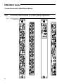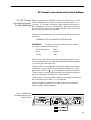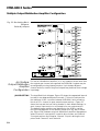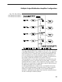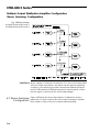
1
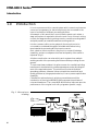
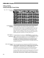
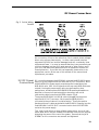
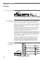
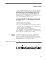
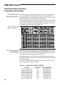
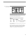
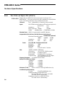
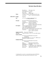
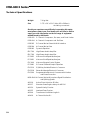
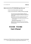
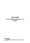
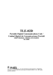
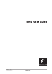
V1.4 29 April 1996
Welcome
Welcome to the MSR-602/604 II Users Manual
This manual is provided to assist sound engineers, installers and
consultants to fully understand the MSR-604 II and to benefit from its
full capability.
As opposed to most manuals, the contents can be read like a book.
At the same time, the information is structured under a series of broad
headings for easy access. So where possible within each section:
· The most immediate information appears at the head of each section
under the main title.
· As you read further into each subsequent section, more detailed,
specific information is given.
Should you have any comments or questions about applying the
MSR-604 II within your application, please write to us at the address in
the warranty section.
MSR-600 II Series
User's Manual
This Manual is the COPYRIGHT of BSS Audio. All reproduction and copying, other than for the legal
owner's personal use, or disclosure of part or whole to a third party, without prior written authorisation, is in violation of the European Copyright Convention. BSS Audio 1996
1
MSR-600 II Series
This equipment has been tested and found to comply with the
following European Standards for Electromagnetic Compatibility.
Emission Specification EN55013 1990 Class B (Associated equipment)
Immunity Specification EN50082/1 1992
Mains Disturbance
(RF Immunity, Fast
Transients and ESD)
EN61000/3/2 1995
For continued compliance ensure that all input and output cables are
wired with cable screen connected to pin 1 of the XLR. The input XLR pin
1 on BSS equipment is generally connected to chassis via a capacitor to
prevent ground loops whilst ensuring good emc compatibility.
2
Table Of Contents
Table Of Contents
1.0
1.1
1.2
2.0
2.1
2.2
3.0
Introduction
4
MSR-604 II Mic/Line Signal Splitter
MSR-602 II Power Supply Unit
5
6
Unpacking
7
Warranty
Warning
7
7
Connections and Control Descriptions 8
3.1
3.2
3.3
3.4
3.5
4.0
AC power connections and control settings
DC power connections
Audio connections
MSR-602 II Controls
MSR-604 II Controls
System Implementation and Use
4.1
4.2
4.3
4.4
4.5
4.6
4.7
5.0
Racking
Grounding
Channel coding
Dual power supply operation
Output drive level setting
Multiple output Distribution Amplifier
configuration
Stereo Summing Configuration
9
11
12
13
14
16
16
18
19
20
20
22
24
Compatibility With Pre Mk II Systems 25
5.1
5.2
5.3
6.0
Installing MSR-604 IIs in a Mk 1 system
25
Installing pre Mk II MSR-604s into a new system
26
Installing a Mk II power supply into a Mk I SYSTEM
and vice versa
26
Appendix A
6.1
6.2
7.0
System block diagram and circuit description
Transient Suppressor replacement
Appendix B
7.1
7.2
Input transformer balancing
Output transformer balancing
27
27
28
29
29
29
8.0
Technical Specifications
30
9.0
Warranty
33
3
MSR-600 II Series
Introduction
1.0
Introduction
It is not uncommon within a sound system which uses microphones as
a source of programme, for that microphone to be connected to the
input of a number of different processing facilities.
An example of this would be in sound reinforcement work where a
stage microphone is required to drive the main ‘front of house’ mixing
console, the stage monitoring mixing console, a mobile recording studio
and quite possibly an outside broadcast recording vehicle.
It is also common within such a system for the microphone to be
connected to considerable lengths of shielded cable before being
terminated at the processing facilitys input connector.
Such a load on the microphone is very much in excess of its design
capability, and as a consequence the level and quality of the sound is
impaired. (Fig. 1)
A further complication can arise within such a system from multiple
earthing as each of the processing facilities would be providing its own
ground.
To overcome these problems it is quite common for a multiple winding
transformer to be used which provides separate secondary windings for
each of the required outputs. This solution will solve the multiple
grounding problems, however it does not tackle the sound level and
quality problem as, being a passive device, it has no power amplification
capability.
Cost effective active electronic solutions proved elusive until the
introduction of the original BSS MSR-604 overcame the problems of
noise and headroom. The current MSR-604 II further improves upon the
performance of the original unit with yet greater dynamic range,
Fig. 1 Microphone
Loading
4
MSR-604 II Microphone Signal Splitter
flexibility of gain and level control, internal bus routing, signal metering and a headphone monitoring facility.
The MSR-604 II is a four channel, four way signal splitting package
and the MSR-602 II is the system power supply capable of supplying
power for 40 channels, that is, 10 separate MSR-604 II units.
1.1 MSR-604
Mic/Line Signal
Splitter
The MSR-604 II has four channels, each of which may be isolated and
used totally independently from the next or, by internal re-configuration,
be interconnected to form distribution amplifier sections with a single
input driving up to 64 outputs.
The low noise floor requirement necessitates a remote power supply
system, the MSR-602 II, which provides the required DC voltages.
A MIC/LINE switch introduces a 20dB input pad, which in combination
with the 5 step GAIN switch allows any input signal below + 33dBu to
be perfectly matched to the MSR-604 II’s dynamic range. The setting up
process is further assisted by the provision of a momentary LISTEN
switch which routes the signal to a calibrated HEADROOM meter and a
headphone monitor amplifier built into the MSR-602 II power supply
unit. Each channel also has a CLIP LED to give constant warning against
signal overdrive. As a further refinement a separate 10dB input pad may
be activated from the front of house mixing console by switching the
desks phantom supply. This remote attenuator allows the engineer to
preserve the channel headroom directly from the consolein the event
that an input is overdriven.
Each channel also provides a separate phantom powering selector switch
providing an independent 48V across the ‘mic input’ connector.
Each channel has two low impedance electronically balanced outputs
on the rear panel to feed the MAIN (Front of House) and the MONITOR
mixing consoles. These outputs may be independently configured by
internal header blocks to drive at mic (+3dBu clip) or at line (+23dBu
clip) levels. A third setting allows these outputs to be driven at +13dBu
clip which gives a gain/headroom structure compatible with earlier
versions of the MSR-604. The two FEED XLR connectors on the front
panel offer microphone level transformer isolated and balanced
outputs.
5
MSR-600 II Series
MSR-602 II Power Supply
1.2 MSR-602 II
Power Supply
The MSR-602 II is the system power supply providing all the necessary DC voltages for the MSR-604 II. It utilises a custom designed low
field toroidal transformer and separate mumetal screen to reduce the
possibility of mains field coupling into the electronic circuitry of the
MSR-604 II.
The HEADROOM LED meter and high quality headphone amplifier give
the operator absolute confidence in signal integrity during setting up,
and provide an indispensable aid to trouble shooting and fault detection.
The signal wiring involved is contained with the power wiring in a
multicore cable for simple interconnection between units.
In addition it also carries the main system ground switch which has
important considerations within a large system for both safety and noise.
PLEASE READ SECTION 4.2 CAREFULLY PRIOR TO OPERATING
THE COMPLETE SYSTEM.
6
Unpacking
Warranty
Warning
2.0
Unpacking
As part of our system of quality control, this product is carefully
inspected before packing to ensure flawless appearance. After
unpacking the units, please inspect for any physical damage and retain
the shipping carton and all relevant packing materials, should the unit
require repacking.
In the event that damage has occurred, immediately notify your dealer,
so that a written claim to cover damages can be initiated.
2.1 Warranty
The MSR-604 II and MSR-602 II units are warranted by BSS to the
original purchaser, against defects in workmanship and materials used in
manufacture, for a period of one year from date of shipment. Faults due
to purchaser misuse, unauthorised modifications or accidents are not
covered by this warranty.
No other warranty is expressed or implied.
If the unit is faulty, it should be sent, shipping prepaid, to an authorised
dealer of the manufacturer stating the faults found.
The serial number must be quoted in all correspondence relating to this
warranty.
2.2 Warning
Because this equipment is connected between the microphone and
mixing console or patching system, it is important for safety and system
noise that a proper earthing system is implemented within the cabling
system.
CONSEQUENTLY SECTION 4.2 OF THIS MANUAL MUST BE READ
PRIOR TO INSTALLATION AND USE.
7
MSR-600 II Series
Connections and Control Descriptions
3.0
Connections and Control Descriptions
Fig. 2 MSR-602 II and
MSR-604 II
8
AC Power Connections and Control Settings
3.1 AC Power
Connections and
Control Settings
Before connecting the MSR-602 II to the AC power source, check
that the voltage selector switch located on the rear panel is correctly set. If a change is necessary, ensure that the mains fuse is
also changed for one of the correct rating. Before connecting the
DC power leads, check that the system ground switch on the rear
panel is also correctly set to ‘earthed’.
The power cord attached to this unit carries the following information label.
WARNING:THIS APPLIANCE MUST BE EARTHED
IMPORTANT:
The wires in this mains lead are colour coded in
accordance with the following code.
Green and yellow :
Earth
Blue
:
Neutral
Brown
:
Live
As the colours of the wires in the mains lead of this appliance may
not correspond with the coloured markings identifying the terminals
in your plug, proceed as follows:
The wire which is coloured green-and-yellow must be connected to
the terminal in the plug which is marked with the letter ‘E’ or by the
earth symbol which is ‘ ‘, or coloured green or green-and-yellow.
The wire which is coloured blue must be connected to the terminal
which is marked with the letter ‘N’ or coloured black.
The wire which is coloured brown must be connected to the terminal
which marked with the letter ‘L’ or coloured red.
Those units that are supplied to the North American market will
have an integral moulded 3 pin connector which is provided to
satisfy required safety standards.
Fig. 3 MSR-602 II
Voltage Switch and
Mains Fuse
9
MSR-600 II Series
Voltage Setting
Safety EarthingAC Power Fusing
Fig. 4 DC Connection
Cabling
3.11 Voltage
Setting
The mains voltage selector switch provides simple, external adjustment for operation on all international AC power standards.
At each switch position there is an acceptable tolerance over which
the performance of the unit will not be affected and this is 90v-130v
for the 120V position, and 180V-260V for the 240V position. If you
subject the unit to voltages in excess of this, you are likely to cause
damage. If the mains voltage is below those specified, there will be
reduced performance before the unit finally fails to work.
3.12 Safety
Earthing
The green/yellow wire of mains cord must always be connected to the
electrical installations Safety Earth or Ground. It is essential for personal
safety, as well as proper operation of the unit, and is internally
connected to all exposed metal surfaces. Any rack framework that this
unit might be mounted into is assumed to be connected to the same
grounding circuit. the MSR-604 II has electronically balanced audio
connections and does not need disconnection of any safety earth for the
avoidance of hum loops.
3.13 AC Power
Fusing
The incoming mains power is fused within the MSR-602 II by the fuse
holder mounted on the rear panel. If it needs to be replaced it must be
properly rated as: 20mm F5A for 240V voltage setting or F6.3A for 120V
voltage setting. It is most important for continued safety that this
specification is strictly adhered to, and you will have found that spare
fuses of this rating are supplied together with your unit and manual.
It is very unlikely that this fuse will fail during normal use, and must be
treated with some caution as to the cause, if it should do so. One of
the most likely reasons will be because the mains voltage switch on
the rear panel is incorrectly set. Another reason can be the inadvert-
10
DC Power Connections
Fig. 5 Cable Wiring
Details
ent connection of line to line rather than line to neutral phase voltages
when using a three phase supply. In either case internal transient
suppressors (VDRs) can become damaged and will consistently blow
replacement fuses. You may be assured that they have protected your
unit from damage, but they will need removal to allow further use of
your unit, and should be replaced as soon as possible to ensure continued protection. If you feel this has happened, please refer to the
appropriate section at the rear of this manual for the removal and
replacement procedure.
3.2 DC Power
Connections
DC connection between the MSR-604 II units and the MSR-602 II power
supply is by the integral multicore cable with 9 pin D connectors. Note
that the MSR-602 II power supply must always be located above the
MSR-604 II units. (NB - this is opposite to the way early MSR-604s were
racked.) Having the power supply at the top gives superior hum
performance, and also places the HEADROOM meter and headphone
amplifier in the most convenient position where they will not be
obscured by cable looms from the FEED outputs. (Fig 4)
The topmost MSR-604 II’s LOOP IN cable is plugged into the power
supplies LOOP OUT connector. Each remaining MSR-604 II is
connected to the unit above it in similar fashion. Finally the male to
female multicore D cable packed with the MSR-602 II is used to loop the
final MSR-604 II’s LOOP OUT connector back to the LOOP RETURN
socket on the power supply.
This ‘ring’ circuit allows a more reliable system set up, since an individual MSR-604 II may be isolated and removed from the rack without
disturbing the power to the rest of the system. Ensure that the JACK
SCREWS on the connectors are secured and tightened.
11
MSR-600 II Series
Audio Connections
3.3 Audio
Connections
The audio connections to the MSR-604 II are via XLR style connectors
on the front and rear panels and their wiring configuration is as shown
in figure 5.
Attention must be given to maintaining a consistent earthing system for
safe and noise free operation. Please refer to section 4.2 for a fuller
explanation and design guides.
INPUT (REAR PANEL): This is electronically balanced, non floating and is for direct connection
to the microphone, DI box or other source of programme. The input is
fully RFI suppressed and has excellent common mode rejection
performance.
Care should be taken to ensure continuity of the pin 1 earth connection.
The 48v phantom powering appears across this input when the channel
phantom switch is operated. (Refer to section 3.2)
MAIN OUT (REAR PANEL): This is electronically balanced, non floating and should be connected to
the ‘front of house’ mixing console or main control area. The remote
attenuator facility looks at this connector for detection of phantom power
voltage. This output should not be connected to an unbalanced input.
For consistent remote attenuator switching and microphone screening, it
is important that the pin 1 earth connection is maintained. (See section
4.5 for configuring the output drive level.)
MON OUT (REAR PANEL):
This is electronically balanced, non floating, and should be connected
to the stage monitor mixing console or ancillary console which is being
operated within the same grounding system.
This output should not be connected to an unbalanced input.
It is probable that the pin 1 earth connection will need to be
disconnected at this point to avoid earth loops. (See section 4.5 for
configuring the output drive level.)
FEED 1 AND FEED 2 These two identical outputs are actively buffered, fully transformer
(FRONT PANEL): balanced and floating with primary/secondary isolation of 2.5kV. They
are for connection to any other facility requiring a signal and are totally
isolated and independent.
There is no connection to the pin 1 earth and all cable screening should
be derived from the receiving end.
It is also important to ensure there is no earth connection to the shell
of the mating female connector as this would make connection to the
MSR-602 II chassis ground and cause potential ground loops.
12
MSR-602 II Controls
Since all the audio connections are balanced, the convention of pin 2
or pin 3 ‘hot’ is of no consequence provided all connections are wired
in a similar manner.
Please refer to appendix B for details of the transformer balancing
options.
3.4 MSR-602 II
Controls
SYSTEM GROUND: This switch, located on the rear panel, is the main grounding point for
all the MSR-604 II units connected to the system.
The switch will connect the electronic/signal ground to chassis earth
when in the ‘EARTHED’ position.
The switch will disconnect the electronic/signal ground from chassis
earth when in the ‘LIFTED’ position.
For a more detailed explanation of the grounding arrangements and
implications of this switch, please refer to section 4.2.
POWER: The LEDs are used to indicate that the power is turned on and present.
The LEDs are wired after the main DC Fuses, so should a fuse blow the
corresponding LED will go out. The DC fuses are on the rear panel and
are clearly marked with value and function. Always replace blown fuses
with the correct value.
LISTEN: HEADROOM The HEADROOM meter is calibrated to show signal level relative to the
METER: clip point. In practice, the red 0db LED will illuminate when the signal
is approximately 0.5dB below actual clip. The meter indication is not
affected by HEADPHONE LEVEL control.
LISTEN: HEADPHONE Adjusts the level of the headphone amplifier from off to full level.
LEVEL: Because the amplifier is designed to produce high monitoring levels into
any impedance headphones extreme caution must be used when setting
headphone levels.
CAUTION! ALWAYS TURN LEVEL DOWN BEFORE LISTENING TO
UNKNOWN SIGNALS. HIGH EFFICIENCY HEADPHONES AND A
HOT SIGNAL CAN PRODUCE DANGEROUS SOUND PRESSURE
LEVELS. OBSERVE THE WARNING SYMBOL NEXT TO THE
HEADPHONE SOCKET.
The gain of the monitor system is such that the amplifier will not clip
or distort even if the level control is turned fully up. This ensures that
if any distortion or clipping is heard it is not due to the monitoring
system and needs to be corrected at the signal source or by adjusting
the channel gain settings.
13
MSR-600 II Series
MSR-604 II Controls
3.5 MSR-604 II
Controls
PHANTOM ON/OFF The MSR-602 II power supply provides each MSR-604 II with 48v DC
for phantom powering capacitor microphones. This is selected by
operating the individual channel switch and it is connected across the
‘input’ connector in the standard phantom powering manner. Typical
current availability is 10mA per channel for a 40 channel system.
Phantom power is indicated by a front panel LED.
It should be noted that phantom powering is interlocked to the LINE/MIC
switch so that when LINE input is selected phantom power and the LED
indicator are disabled.
LINE/MIC This switch introduces a 20dB pad into the input circuit of the unit, and
raises the input impedance to suit line level signals. In the mic position
the maximum signal level is +13dBu (with the GAIN set to -10dB). In
the line position phantom powering is disabled and the maximum
permitted signal level is +33dBu (with the GAIN set to -10dB).
GAIN The GAIN switch allows the input amplifier gain to be changed in 10dB
steps from -10dB to +30dB to precisely match the input signal to the
internal headroom of the MSR-604 II. Combined with the very low
inherent noise of the input stage this ensures that none of the dynamic
range of the source is lost.
The absolute system gain is dependent upon the internal system
configurations chosen, but with factory default settings and in the MIC
position the gain indicated on the GAIN switch setting is correct, i.e.
with a mic input, 0dB gain selected and default jumper settings the
output level is the same as the input signal.
CLIP LED The CLIP LED which is situated below the GAIN switch illuminates
when the peak signal level approaches within 1dB of clip. It features
a fast acting full wave rectifier and a hold circuit which ensure that all
transient peaks are unambiguously indicated.
14
MSR-604 II Controls
REMOTE ATTENUATOR A 10dB input pad is activated when the channel detects a +48v phantom signal is present on the MAIN OUTPUT. This allows the front of
house mixing engineer to remotely reduce the input signal if he detects that the channel is being overdriven. This is a not uncommon
occurrence in live rock and roll, when musicians get into the spirit of
a performance and sing louder than during sound checks.
A front panel LED indicates when REMOTE ATTENUATOR is active.
Because the attenuator slightly degrades the noise and common mode
performance of the unit it is recommended that the system is set up and
calibrated without the remote attenuator activated, and that it is reserved
for emergency use as described above.
The remote attenuator function cannot be disabled, so the engineer
should observe the same caution with the desk phantom switch as he
would if a phantom powered microphone were directly connected to the
desk input.
CAUTION! USE OF THE DESK PHANTOM SWITCH IS ALMOST
CERTAIN TO PRODUCE AN AUDIBLE CLICK SO IT IS
RECOMMENDED THAT THE CHANNEL BE CLOSED BRIEFLY DURING
SWITCHING.
LISTEN Pressing the LISTEN switch connects the channel signal to the
HEADROOM meter and headphone amplifier on the MSR-602 II power
supply. It is a momentary switch which needs to be held in during
monitoring.
The listen bus is arranged in such a way that only one channel will
register on the monitor section at any time. If two listen switches are
pressed at the same time the one that is closest in the chain to the PSU
will register. See the MSR-602 II controls section for further details.
CAUTION! ALWAYS TURN LEVEL DOWN BEFORE LISTENING TO
UNKNOWN SIGNALS. HIGH EFFICIENCY HEADPHONES AND A
HOT SIGNAL CAN PRODUCE DANGEROUS SOUND PRESSURE
LEVELS. OBSERVE THE WARNING SYMBOL NEXT TO THE
HEADPHONE SOCKET.
15
MSR-600 II Series
System Implementation and Use
Racking
4.0
System Implementation and Use
4.1 Racking
It is envisaged that a number of the MSR-604 II units will be racked
together with one MSR-602 II power supply.
The metal case of the MSR-604 II is not connected to the electronic 0V,
and is taken to the mains safety ground via its DC lead connection into
Fig. 6 Physical
Dimensions
16
Racking
the MSR-602 II. The MSR-602 II has a permanent safety ground connection via the power cord.
Please read section 4.2 for discussion of grounding of the electronic
0v.
The MSR-602 II power supply unit, unlike its predecessor has been
designed for mounting at the TOP of a rack, above the MSR-604 II units
it powers. In a properly installed MSR system mains induced hum from
the PSU will be unmeasurable.
If a power supply unit needs to be mounted below a MSR-604 II, the
system should be checked for mains induced hum. The following steps
may be taken to reduce it.
a) Leave a gap of at least 1U between the PSU and the closest MSR-604
II.
b) Contact your BSS agent to obtain a mumetal shield which may be
affixed to the top cover plate of the MSR-602 II.
c) Reduce the number of units in the system. (The stray magnetic field is
proportional to the current demanded from the PSU.)
In all cases, the MSR-602 II and the MSR-604 II’s MUST be fully
supported along their depth. For touring system, failure to observe this
precaution will cause eventual metal failure of the MSR-II cases which
will not be covered by the guarantee.
The physical dimensions and mounting points for the MSR-604 II and
MSR-602 II are identical. They are shown in figure 6.
In large touring systems, it is envisaged that the rear panel input and
output connectors will be wired into a multiway distribution panel
forming part of the same rack. In this way, all cabling for the main
system is kept tidy and away from the front of the unit. The isolated
feeds appearing on the front of the unit are available for the external
facilities, and their connection will not interfere with the in-house
cabling system.
As with any microphone stage box system it is advisable to avoid the
close proximity of heavy power cabling, power transformers and all
forms of lighting control equipment.
17
MSR-600 II Series
Grounding
Fig. 7 MSR Grounding
4.2 Grounding
In any multi-channel audio system where low level signals are being
routed, it is important to ensure a consistent and positive earthing
system to minimise any possible noise interference and hum loops.
With the use of microphones it is especially important to ensure reliable
earthing and screening not only for these noise considerations but also
for safety of the performers.
Figure 7 shows the internal grounding arrangements for the MSR-602 II
and MSR-604 II, and figure 8 shows one of the common earth and
grounding arrangements for a complete MSR-600 system, where the
microphone shielding is held directly to ground.
The star grounding point is the main ‘front of house’ mixing console, and
this earth is the one used to shield all cables and the microphone body.
There should be no connection between this earth and that of the MSR604 II chassis, and the system ground switch on the MSR-602 II rear
panel should be set to ‘lifted’.
All the metal casing associated with the MSR-600 II system will be
grounded via the MSR-602 II power cord, and through a separate
conductor within the DC power lead to the MSR-604 II units. The
electronic 0v ground will be connected to the main front of house
mixing console earth system via the interconnecting audio cables.
Fig. 8 System
Grounding
Arrangements
18
Channel Coding
In general the stage monitor console will be connected to the stage
mains power grounding system so the signal connecting cables to the
‘MON OUTPUT’ connector will require the earth connection to be
disconnected. That is, the cable screening will be derived from the
monitor console, but should not be connected to the electronic 0v
earthing system of the MSR-604 II via pin 1 of the connector. This
disconnection would be implemented either in the connector, or at the
monitor console multiway connector wiring point.
Other systems of earthing can be implemented, such as using the stage
earth as the main star point, in which case the system ground switch
would be set to ‘grounded’, or to use the stage monitor console as the
main star point.
In any system it is important to remember:
a) Choose one star point for all grounding.
b) Ensure all microphone screening is permanently held to this ground.
c) Ensure that the two main earthing systems, namely stage and front of
house, do not accidently short together.
d) Avoid sending signal currents along cable screens.
If these simple guide lines are followed, then implementation of the
MSR-600 system will be completed without any troublesome earthing
faults, and full safety will be implicit within the design.
4.3 Channel
Coding
In a system with more that one MSR-604 II unit, identifying which
channel of which MSR is the actual system channel will become
necessary, and the small pre-numbered self-adhesive labels supplied
with the MSR-604 II can be used for this purpose. Figure 9 shows the
fitting of these labels to the MSR-604 II front panel.
Fig. 9 Channel Coding
19
MSR-600 II Series
Dual Power Supply Operation
Output Drive Level Setting
4.4 Dual Power
Supply Operation
The power supply of the MSR-600 system performs a vital role within
the sound system and although designed to exacting standards for
ultimate reliability, some systems will require a back-up which would
automatically take over on failure of the main supply.
This is implemented within the MSR-600 system such that any two MSR602 II units can be directly connected together. Both units are switched
on at all times, and power sharing ensures that the system will continue
to operate should either unit fail (see figure 10).
Fig. 10 Dual Power
Supply Connection
4.5 Output Drive
Level Setting
Each MAIN output and MON output can be individually set to drive at
mic or line level. A third setting which may be described as ‘Hot mic
level’ is also available in order to provide a headroom structure which is
compatible with previous versions of the MSR-604.
All outputs are set to mic level when the MSR-604 II leaves the factory.
Note that the FEED outputs are set for clip at +3dBm (mic level) only and
cannot be changed.
The OUTPUT LEVEL SELECT header blocks are clearly marked on the
main PCB and are described in Table 1
TABLE 1
OUTPUT LEVEL SELECT JUMPERS
Function
Jumper No. PCB identification
Channel 1 MAIN OUT
JP2
CH1 MAIN O/P
Channel 1 MON OUT
JP1
CH1 MON O/P
Channel 2 MAIN OUT
JP6
CH2 MAIN O/P
Channel 2 MON OUT
JP5
CH2 MON O/P
Channel 3 MAIN OUT
JP10
CH3 MAIN O/P
Channel 3 MON OUT
JP9
CH3 MON O/P
Channel 4 MAIN OUT
JP14
CH4 MAIN O/P
Channel 4 MON OUT
JP13
CH4 MON O/P
20
Fig. 11 Output Level
Select Jumpers
The permissible settings are shown in Figure 11, and the effects of
each on system gain and headroom is described in Table 2. Note that
combinations of header settings other than those shown should not be
used as they do not give a proper balanced drive.
TABLE 2 OUTPUT LEVEL SELECT HEADROOM AND GAIN
STRUCTURE
Setting
3dBm
13dBm
23dBu
Output clip System gain
Description
Level
/dB (Note 1)
+3dBm
0
Mic level output. Factory default
+13dBm
+10
MSR-604 pre Mk II compatibility
+23dBu
+20
Line level output
(Note 1. Gain between input XLR and output XLR with channel Gain switch set to 0dB
and input pad set to MIC).
NOTE: The output levels are referred to using both dBm and dBu for
different settings. This is because the unit is capable of driving 3dBm or
13dBm into a 600Ω load but the 23dBu output, although capable of
driving 600Ω will, drop slightly in level for loads below 2kΩ.
21
MSR-600 II Series
Multiple Output Distribution Amplifier Configuration
Fig. 12 Bus Linking Block
Diagram.
Default Jumpers
4.6 Multiple
Output Distribution
Amplifier
Configuration
For use as a distribution amplifier, or in any situation where more than
four outputs per channel are required, the MSR-604 II system may be
reconfigured by moving internal jumpers. Up to sixteen adjacent
channel sections, a total of sixty four outputs may be driven from a single
input stage.
JUMPER SETTING The simplified block diagram, Figure 12 shows the segmented internal
bus which runs between adjacent channels. This bus is continued via
the multiway LOOP connector between MSR-604 II units, allowing
blocks of D.A. channel to span several output sections. Figure 12
shows the bus and the bus linking headers in their default settings, i.e.
each channel input section is connected to its own output section.
The default jumper positions are identified on the PCB by a white
block printed adjacent to the relevant jumper pins. By way of example, Figure 13A illustrates a typical distribution amplifier arrangement
where Channel 1 input section is used to drive its own and Channel
2’s output sections and, likewise, Channel 3 input is driving the outputs of both Channel 3 and Channel 4.
22
Multiple Output Distribution Amplifier Configuration
Fig. 13A Bus Linking
Ch1 Drives Out1 and 2
Ch3 Drives Out3 and 4
The signal labelled EXBUS-OUT passes via the LOOP OUT connector
to the EXBUS-IN terminal in the LOOP IN connector on the adjacent
unit, allowing a D.A. channel to span more than one MSR-604 II unit.
It will be apparent from the above example that the permutations of
D.A. blocks that can be configured within a system is limited only by
the number of MSR-604 IIs that are connected in the rack.
The limiting factor on how many channels may be linked is the parallel loading that occurs on the drive from the input stage. The recommended maximum is sixteen, which equates to sixty four outputs. This
will result in an overall drop in system gain of about 0.7dB but should
not significantly affect noise or distortion.
It is strongly advised that in order to have a configuration work first
time, that the required system is first planned out on paper, and with
reference to Figures 12, 13A and 13B, a list of jumper settings is
produced. Implementing the system then becomes a simple mechanical task of setting the relevant jumpers.
23
MSR-600 II Series
Multiple Output Distribution Amplifier Configuration
Stereo Summing Configuration
Fig. 13B Bus Linking
In1+In2 Drives Out1 and 2
In3+In4 Drives Out3 and 4
CONTROLS When a group of channels is linked as a D.A., the controls associated
with the chosen input section are used to set the required operating
conditions. the controls on the other channels are disabled, except for
the CLIP LEDs and the LISTEN switches which may be used to confirm
that the signal is reaching all the linked output stages.
4.7 Stereo Summing
Configuration
24
Figure 13B above shows an alternate bus configuration where a
stereo pair of inputs is used to drive two output channels in parallel.
Each output is a sum of the pair of inputs reduced by 6dB.
Compatibility With Pre MkII Systems
Installing MSR-604 IIs in a Mk 1 System
5.0
Compatibility With Pre MkII Systems
Limited compatibility exists between early MSR-604 systems and
MSR604 II units using adaptor leads to interconnect the power cables.
Please order adaptor leads as MSR-604 Mk I adaptor kit Z-MSRIIADK01. This pair of cables is required for any of the system combinations
described below. Only one adaptor set is required per system no
matter how many new units are to be to be installed.
5.1 Installing
MSR-604 IIs in a Mk I
System
The MSR-604 II may be used to extend an existing rack which uses
earlier versions of MSR-600 components. Although the Mk II units will
perform better than the originals, some of the enhanced performance
and features will be lost. In general the dynamic range will be reduced
by about 2dB and the LISTEN monitoring function will not be available.
Also channel bus linking will be restricted to operating within individual
MSR-604 II units.
SETTING SYSTEM Remove the top cover plates on MSR-604 IIs and locate the two
JUMPERS jumpers JP14 and JP15 next to the aluminium regulator heatsink.
These jumpers will be shipped set to the factory default position,
indicated by a solid bar printed on the PCB. Move the jumper blocks
away from the default to cover the left and centre pins. It will be
noted that yellow LEDs LD9 and LD10 do not now illuminate when
power is applied. Replace the cover plate before installing in the
rack.
RACK INSTALLATION
The new units should be mounted at the top of the rack, away from
the MSR-602 power supply. If more than one MSR-604 II is being
installed, the LOOP IN/LOOP OUT connectors are ‘daisy’ chained’
25
MSR-600 II Series
Installing Pre Mk II MSR-604s Into a New System
Installing a Mk II Power Supply Into a Mk I System and Vice Versa
5.2 Installing Pre
Mk II MSR-604s Into
a New System
RACK INSTALLATION
5.3 Installing a
Mk II Power Supply
Into a Mk I System
and Vice Versa
26
together as described in section 3.2. Finally the pair of adaptor leads
are used to insert the Mk II units into the systems power circuit.
Early MSR-604 units may be added to a Mk II system, but will gain no
improvement in performance from the new system. They will run
slightly warmer since they will be running from a higher DC voltage
supply but there is no danger of damage or impaired reliability.
No changes are required to any internal jumpers or settings and
provided that the Mk I units are installed at the ‘end’ of the DC
daisychain, the performance of the Mk II units will not be affected in
any way.
The Mk I MSR-604s should be mounted at the bottom of the rack,
away from the power supply. Using the adaptor leads connect the
Mk I units between the MSR-602 II LOOP RETURN socket and the
final MSR-604 II LOOP OUT socket. If the units are wired into the DC
loop wiring at a different point, the LISTEN BUS and the EXBUS-IN/OUT linking between Mk II MSR units will be broken, disabling these
functions.
Mixing Mk I and Mk II power supplies and systems is not generally
recommended. Since they are designed to work at different DC rail
voltages, performance and facility will be reduced to the lowest common
denominator at best. Contact your BSS agent for availability and
Appendix A
System Block Diagram and Circuit Description
6.0
Appendix A
6.1 System Block
Diagram and
Circuit Description
advice if a replacement or a second power supply is required for a Mk
I system.
Figure 14 shows the block diagram of the audio section of the MSR604 II. The DC supply regulator circuits (not shown) are common to
all channels. The rails to each channel are protected by fusible
resistors so that in the event of a short circuit fault in one channel the
other three are not affected.
The input signal passes via RFI filters to the MIC/LINE switch, a balanced 20dB pad, and then to the REMOTE ATTENUATOR. This is a
Fig. 14 MSR-604 II Block
Diagram
27
MSR-600 II Series
Transient Suppressor Replacement
balanced 10dB pad using a relay controlled by a circuit which monitors the MAIN OUTPUT XLR for the presence of phantom DC voltage.
The balanced signal then passes through the optional input transformer, if fitted, and DC blocking capacitors to the low noise INPUT
AMPLIFIER. This stage provides the common mode rejection trim,
GAIN switch and provides a line level low impedance unbalanced
drive signal to the BUS LINKING HEADERS. In the default mode the
channel signal is not routed to the bus but is passed to the channel
output stages.
The OUTPUT AMPLIFIER has two out of phase line driving outputs
which are DC blocked and passed to both the balanced MAIN OUTPUT
ATTENUATOR and the balanced MONITOR OUTPUT ATTENUATOR.
The signals are then fed to the MAIN OUT and the MON OUT XLRs
respectively. The low impedance attenuators ensure that a faulty cable
or load on one output will not affect the other and also allow the output
drive levels to be independently set to +23dBu, +13dBm, or +3dBm at
clip. If the optional output transformers are installed, they are fitted in
place of the attenuators and the output headroom is preset at +3dBu.
The FEED AMPLIFIER buffers the signal and drives the dual secondary
isolating FEED TRANSFORMER which is connected to the two FEED
output XLRs mounted on the front panel.
6.2 Transient
Suppressor
Replacement
The LISTEN AMPLIFIER buffers the signal before presenting it to the
LISTEN switch. This in turn is connected to the listen bus for monitoring on the HEADROOM METER and HEADPHONE AMPLIFIER which
are located in the MSR-602 II power supply.
The primary of the mains transformer within the MSR-602 II is protected against high voltage spike interference by two voltage dependent resistors. These provide a short circuit to voltage peaks in excess
of their maximum rating.
Should the MSR-602 II be inadvertently connected to 3 phase line/line
voltages, or to 240V when selected to 120V, or any other incorrect
voltage, these suppressors are likely to fail in a protective short circuit
mode. This will be demonstrated by repeated mains fuse failure when
powering up the unit.
Even in this case of extreme overvoltage, the MSR-602 II is protected
against failure, and the simple removal of these suppressors will allow
the unit to be used again. However, it is important that they are
replaced as soon as possible to ensure continued protection.
Fig. 15 Transient
Suppressor Details
28
Appendix B
Input Transformer Balancing
Output Transformer Balancing
7.0
Appendix B
7.1 Input
Transformer
Balancing
Figure 15 indicates the location and specification for the suppressors.
In some situations it might be necessary to provide a transformer
balanced input and provision has been made within the MSR-604 II for
it’s mounting.
Please order as ‘MSR-604 II input transformer kit Z-MSRTXIII-01’. This is
per channel, with four required for one MSR-604 II unit. Full fitting
instructions are provided with this kit.
7.2 Output
Transformer
Balancing
Provision has been made within the MSR-604 II to fit 600 ohm transformers to the ‘main’ and ‘mon’ outputs to provide floating and isolated
outputs.
29
MSR-600 II Series
Technical Specifications
8.0
Technical Specifications
MSR-604 II
Please order as ‘MSR-604 II balanced output transformer kit ZMSRTX0II-01’. This is per channel with four required for one MSR-604
II unit. Full fitting instructions are provided with this kit.
Channels
Four: Independant or internally interconnected
Inputs
XLR-3F Electronically balanced (Transformers optional)
Microphone
Line
Impedance
2kΩ
10kΩ
Max. input level +13dBu
+33dBu
CMRR
>90dB @ 1kHz
>75dB 50Hz to 10kHz
Phantom Power 48VDC via panel switch and LED indicator
Outputs Main (FOH) & Mon, XLR-3M, Electronically balanced
(Transformers optional)
Max level (internally preset)
+3dBm
+13dBm +23dBu
Impedance
<23Ω
<71Ω
<100Ω
Max load
200Ω
600Ω
600Ω
Feeds:
Two, XLR-3M, Transformer balanced
Max level
+3dBu
Impedance
<50Ω
Max load
600Ω
Isolation
2.5kV ACrms for 1 minute
Gain
-40dB to +50dB in 10dB steps
Gain switch
-10, 0, 10, 20, 30dB via panel
Mic/Line pad
0/-20dB via panel
Remote pad
0/-10dB via F.O.H. phantom
Output scaling
+20/+10/0dB via internal jumper
blocks (Main & Mon only)
Frequency Response
<+/-0.5dB 20Hz to 20kHz
Noise (E.I.N.) (20Hz to 20kHz)
-10dB gain
<-114dBu
0dB gain
<-121dBu
10dB gain
<-124dBu
20dB gain
<-125dBu
30dB gain
<-126dBu
Distortion (T.H.D.)
<0.01% 20Hz to 20kHz @ 10dB below clip
Level Metering & Monitoring
Channel
Clip LED @ 1dB below clip
Headroom meter on MSR-602 II PSU
Six point LED meter: 0,-1,-3,-6,-12,-26dB
Via Listen switch (momentary)
Headphone monitor on MSR-602 II PSU
Via Listen switch (momentary)
30
Technical Specifications
Stereo/Mono
Load Impedance
Max output
Level control
MSR-602 II
1/4in Jack socket
4Ω to 600Ω
1W rms
-90dB to 0dB
Power
+/-27VDC, +48VDC from MSR-602 II PSU only
Connectors
9 pin ‘D’, with lock jackscrews
Weight
3.8kg Net
Size
1.75" x 19" x 11.6" (44 x 482 x 293 mm)
excluding connectors
AC Input
90-130/180-260VAC 50/60Hz @ 150VAC
Connector
3 pin IEC with locking clip
Voltage selector Rear panel 120/240V
Switch
Rear panel High-inrush
Fuse
Rear panel F6.3A(120V) / F5A(240V)
DC Outputs
+27V unregulated @ 4A max: low ripple
-27V unregulated @ 4A max: low ripple
+48V +/-5% regulated @ 500mA max
Rear panel Fuses F5A(+27V) F5A(-27V) F500mA(+48V)
Connectors
9 pin ‘D’ female Loop out
9 pin ‘D’ male Loop return
System Ground Lift
Indicators
Rear panel Slide switch
3 LEDs, post fuse, on +27V, -27V and +48V outputs
Headroom Meter
Via Listen bus and MSR-604 II Listen switch
(momentary)
Six point LED meter 0, -1, -3, -6, -12, -26dB ref clip
Input via DC Loop out connector
Headphone Monitor
Via Listen bus and MSR-604 II Listen switch
(momentary)
Input:
via DC Loop out connector
Connector
Stereo/Mono 1/4 Jack socket
Load impedance 4Ω to 600Ω
Max output
4Ω:860mWrms 200Ω:750mW rms
Level control
Continuously variable -90dB to 0dB
Headroom
>MSR-604 II channel clip
In keeping with our policy of continued improvement, BSS Audio
reserve the right to alter specifications without prior notice.
31
MSR-600 II Series
Technical Specifications
Weight
7.0 kg Net
Size
1.75" x 19" x 11.6" (44 x 482 x 293mm)
excluding connectors
Should you experience any difficulty in operating this equipment please contact your local dealer who will also be able to
supply you with information on the full range of equipment
manufactured by BSS Audio.
DPR-402
2 Channel Compressor, De-esser, and Peak Limiter
DPR-404
4 Channel Compressor and De-Esser
DPR-502
2 Channel Noise Gate with Midi Interface
DPR-504
4 Channel Noise Gate
DPR-901
Dynamic Equaliser
EPC-760
High Power Audio Amplifier
EPC-780
High Power Audio Amplifier
FCS-926
Varicurve Dual Equaliser/Analyser
FCS-920
Varicurve Dual Equaliser/Analyser
FPC-900
Varicurve Remote Control System
FCS-960
2 Channel 30 Band Graphic Equaliser
FDS-310
2/3/4 Way Variable Electronic Crossover
FDS-318
Stereo Multimode Electronic Crossover
FDS-360
Programmable Electronic Crossover with Limiters
and Phase Correction.
MSR-604 II 4 Channel Active Microphone Signal Distribution
and Splitting System.
32
AR-116
Active Direct Injection (DI) Box.
AR-117
Phantom Powering Accessory for AR-116.
AR-130
System Polarity Checker.
AR-125
Lead and Fuse Checker.
AR-204
Transformer Line Balancing Unit.
AR-416
4-Channel Active D.I.
Warranty
9.0
Warranty Information
This unit is warranted by BSS Audio to the original end user purchaser
against defects in workmanship and the materials used in its manufacture for a period of one year from the date of shipment to the end user.
Faults arising from misuse, unauthorised modifications or accidents
are not covered under this warranty. No other warranty is expressed
or implied.
If the unit is faulty it should be sent, in its original packaging, to the
supplier or your local authorised BSS Audio dealer with shipping
prepaid.
You should include a statement listing the faults found. The unit’s serial
number must be quoted in all correspondence relating to a claim.
We recommend that you record your purchase information here for
future reference.
IMPORTANT
Dealer Name:
Dealer Address:
Post/Zip Code:
Dealer Phone No.:
Dealer Contact Name:
Invoice/Receipt No.:
Date of Purchase:
Unit Serial Number:
In keeping with our policy of continued improvement, BSS Audio
reserves the right to alter specifications without prior notice.
This product was designed, developed and produced by BSS Audio,
Hertfordshire, England.
Phone (+44) (0)1707 660667. Fax (+44) (0)1707 660755.
33
MSR-600 II Series
USER NOTES
34
USER NOTES
35
MSR-600 II Series
USER NOTES
36