1
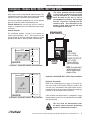
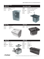
Delfield
™
®
200 & 300 SERIES
Service and Installation Manual
Please read this manual completely before attempting to install or operate this equipment!
Notify carrier of damage! Inspect all components immediately. See page 2.
Drop In and Undercounter Products
N
CAUTIO
TION
A
M
R
O
INF
T
N
A
T
R
USE
IMPO
E
R
O
F
E
ONS!
I
T
C
READ B
U
R
NST
I
E
S
E
H
VE T
A
S
E
S
A
PLE
March 2009
200 and 300 Series Service and Installation Manual
Serial Number Information
Contents
Serial Number Information......................................................... 2
Receiving And Inspecting Equipment......................................... 2
Specifications.............................................................................. 2
Installation................................................................................3-4
Operation..................................................................................... 5
Maintenance................................................................................ 5
Replacement Parts...................................................................6-8
Wiring Diagram........................................................................... 8
Standard Labor Guidelines......................................................... 9
Standard Warranty...............................................................10-11
Models
Serial Tag Location
N225, N227
On the compressor stand next to the temperature control
203, 204, 204P, 248, 250, 305 On the bottom of the ice chests
240
On the back
242
On the bottom of the sink
307
Underneath the top
Always have the serial number of your unit available when calling
for parts or service.
©2009 The Delfield Company. All rights reserved. Reproduction without
written permission is prohibited. “Delfield” is a registered trademarks of The
Delfield Company.
Receiving And Inspecting The Equipment
Even though most equipment is shipped packaged, care
should be taken during unloading so the equipment is not
damaged while being moved into the building.
1. Visually inspect the exterior of the package and skid or
container. Any damage should be noted and reported to
the delivering carrier immediately.
2. If damaged, open and inspect the contents with the
carrier.
3. In the event that the exterior is not damaged, yet upon
opening, there is concealed damage to the equipment
Specifications
MODEL
L
D
H
16.56”
(42.1cm)
27.87”
26.75”
115lbs
(70.8cm) (67.9cm) (52kg)
30”
27.87”
26.75”
191lbs
(76.2cm) (70.8cm) (67.9cm) (87kg)
DROP-IN REEZERS WITH LEXAN® LID
notify the carrier. Notification should be made verbally as
well as in written form.
Request an inspection by the shipping company of the
damaged equipment. This should be done within 10 days
from receipt of the equipment.
Visually inspect the refrigeration package. Be sure lines
are secure and base is still intact.
Freight carriers can supply the necessary damage forms
upon request.
Retain all crating material until an inspection has been
made or waived.
4.
5.
6.
7.
SHIP
CUTOUT SIZE
WEIGHT
CABINET H.P.
CAPACITY
AMP
VOLT
NEMA
PLUG
DESIGN
LOAD BTU
SYSTEM
CAP. BTU
EVAP BTU/
TD/TEMP
25.75” x 14.62”
(65.4cm x 37.1cm)
6 gal.
1/5
5.3
115
5-15P
292
411
20/20°/-23°
25.75” x 28.00”
(65.4cm x 71.1cm)
12 gal.
1/5
5.3
115
5-15P
473
532
28/19°/-22
DROP-IN FREEZERS
N225
N227
N225L
16.56”
(42.1cm)
27.87”
26.75”
115lbs
(70.8cm) (67.9cm) (52kg)
25.75” x 14.62”
(65.4cm x 37.1cm)
6 gal.
1/5
5.3
115
5-15P
292
411
20/20°/-23°
N227L
30”
(76.2cm)
27.87”
26.75”
191lbs
(70.8cm) (67.9cm) (87kg)
25.75” x 28.00”
(65.4cm x 71.1cm)
12 gal.
1/5
5.3
115
5-15P
473
532
28/19°/-22
DROP-IN WATER STATIONS AND ICE STORAGE
203
ice chest
20.25”
(51.4cm)
20.25”
23.25”
52lbs
(51.4cm) (59.1cm) (24kg)
19.25” x 19.25”
(48.9cm x 48.9cm)
90lbs
(41kg)
N/A
N/A
N/A
N/A
N/A
N/A
N/A
204
water and ice
station
24”
(61.0cm)
21”
23.5”
47.5lbs
(53.3cm) (59.1cm) (22kg)
21” x 17.75”
(53.3cm x 45.1cm)
45lbs
(20kg)
N/A
N/A
N/A
N/A
N/A
N/A
N/A
204P
water and ice
station
24”
(61.0cm)
21”
27”
47.5lbs
(53.3cm) (68.6cm) (22kg)
21” x 17.75”
(53.3cm x 45.1cm)
45lbs
(20kg)
N/A
N/A
N/A
N/A
N/A
N/A
N/A
240
ice chest with
cover
21”
(53.3cm)
17.5”
17”
36lbs
(44.5cm) (43.2cm) (16kg)
—
75lbs
(34kg)
N/A
N/A
N/A
N/A
N/A
N/A
N/A
248
water and ice
station
31”
(78.7cm)
15”
22.5”
28lbs
(38.1cm) (57.2cm) (13kg)
28” x 12.5”
(71.1cm x 31.8cm)
45lbs
(20kg)
N/A
N/A
N/A
N/A
N/A
N/A
N/A
305
ice chest with
cover
21.25”
(54.0cm)
15.25”
13”
18lbs
(38.7cm) (33.0cm) (8kg)
12.5” x 17.75”
(31.8cm x 45.1cm)
45lbs
(20kg)
N/A
N/A
N/A
N/A
N/A
N/A
N/A
307
glass filler
12”
(30.5cm)
12”
9.5”
7lbs
(30.5cm) (24.1cm) (3kg)
9.00” x 9.00”
(23cm x 23cm)
—
N/A
N/A
N/A
N/A
N/A
N/A
N/A
17” x 12.5”
(43.2cm x 31.8cm)
—
N/A
N/A
N/A
N/A
N/A
N/A
N/A
N/A
N/A
N/A
N/A
N/A
N/A
N/A
UNDERCOUNTER SINKS, WATER STATIONS AND ICE STORAGE
242
UC sink & faucet
18”
(45.7cm)
13.5”
12.75”
20lbs
(34.3cm) (32.4cm) (9kg)
250
UC sink, ice chest 46”
14.12”
22.75”
81lbs
and water station (116.8cm) (35.9cm) (57.8cm) (37kg)
45” x 13”
45lbs
(114.3cm x 33.0cm) (20kg)
Delfield
™
For customer service, call (800) 733-8829, (800) 733-8821, Fax (989) 773-3210, www.delfield.com
®
200 and 300 Series Service and Installation Manual
Installation - Models N225, N225L, N227 And N227L
Location
Units in this manual are intended for indoor use only. The
refrigeration system has been factory tested and should
require no further adjustment during installation.
For the most efficient refrigeration, be sure to provide
good air circulation inside and outside the unit.
Outside Cabinet: Be sure that the unit has access to
ample air. Avoid hot corners and locations near stoves
and ovens.
Counter Cutouts
For installation provide a cutout in the counter as
shown (see illustration 1 or 2). The counter must be
sturdy enough to hold the combined weight up to 300
pounds of the drop-in and the product stored inside.
25.75"
65.4cm
N225 N225L N227
or N227L DROP-IN
TO
UT
1.00"/2.5cm (min.)
CU
.75"/1.9cm
radius
The louver provided must be installed
in front of the condensing unit’s finned
coil (see illustration 3). A second cutout
must be made at the rear or end of
the equipment to allow air flow through
the unit. No louver is provided for the
second cutout. Any restriction to the
proper air flow, total or partial, will void
the compressor warranty.
14.62"
37.1cm
1.00"/2.5cm (min.)
COUNTERTOP
Illustration 1. Model N225 & N225L cutout dimensions
25.75"
65.4cm
LOUVER
13.00" x 25.00"
33.0cm x 63.5cm
1.00"/2.5cm (min.)
TYPICAL
COUNTER
CABINET
LOUVER CUTOUT SIZE
12.00" x 23.50"
30.5cm x 59.7cm
(typical installation)
NOTE: A second cutout
(without louver) must
also be made to allow
proper air flow.
Illustration 3. N225 N225L N227 & N227L louver installation
CU
TO
U
T
Electrical Connection
28.0"
71.1cm
.75"/1.9cm radius
COUNTERTOP
1.00"/2.5cm (min.)
Illustration 2. Model N227 & N227L cutout dimensions
Refer to the amperage data on page 2, the serial tag,
your local code or the National Electrical Code to be
sure the unit is connected to the proper power source.
A protected circuit of the correct voltage and amperage
must be run for connection of the line cord.
If the unit does not operate after it is plugged in, check
the thermostat to see if it was inadvertently turned OFF
during installation.
The unit must be disconnected from
the power source whenever performing
service or maintenance functions.
Delfield
™
®
For customer service, call (800) 733-8829, (800) 733-8821, Fax (989) 773-3210, www.delfield.com
200 and 300 Series Service and Installation Manual
Installation - Models 203, 204, 204P, 240, 242, 248, 250, 305 And 307
Location
Drain
Units in this manual are intended for indoor use only.
Provided 1” (2.5cm) drain, nut and washer must be
field installed to an appropriate container or floor drain
following local code requirements. Sinks come standard
with 1-1/2” basket strainer assemblies.
Avoid hot corners and locations near stoves and
ovens.
Counter Cutouts
For installation, provide a cutout in the counter sized
according to the chart below. The counter must be
sturdy enough to hold the combined weight up to 300
pounds of the drop-in and the product stored inside.
Model
Cutout Size
Mounting
Studs
1/2” IPS
Water
Hookup
Drain
203
ice chest
19.25” x 19.25”
(48.9cm x 48.9cm)
N/A
N/A
(1) 1”
204
water and ice
station
21” x 17.75”
(53.3cm x 45.1cm)
4
1
(2) 1”
204P
water and ice
station
21” x 17.75”
(53.3cm x 45.1cm)
4
1
(2) 1”
240
ice chest with cover N/A
N/A
N/A
(1) 1”
242
UC sink & faucet
17” x 12.5”
(43.2cm x 31.8cm)
N/A
2
(1) 1-1/2”
248
water and ice
station
28” x 12.5”
(71.1cm x 31.8cm)
4
1
(2) 1”
250
UC sink, ice chest
and water station
45” x 13”
N/A
(114.3cm x 33.0cm)
3
(2) 1”
(1) 1-1/2”
305
ice chest with cover 12.5” x 17.75”
(31.8cm x 45.1cm)
4
N/A
(1) 1”
307
glass filler
4
1
(1) 1”
9.00” x 9.00”
(23cm x 23cm)
Water Connection
All 1/2” (1.3cm) IPS water inlets must be field connected
following local code requirements.
Mounting Studs
13.50” (34.3cm)
19.25” (48.9cm)
204/204P Stud Location
Equipment with mounting studs are pictured below.
Mark the stud locations according to the measurements
or place the equipment in the cutout to mark the stud
locations. Drill 0.37” (1.0cm) diameter holes through the
counter for the studs.
29.50” (74.9cm)
248 Stud Location
10.12” (25.7cm)
307 Stud Location
19.375” (49.2cm)
305 Stud Location
22.00” (55.9cm)
204/204P Stud Location
10.12” (25.7cm)
307 Stud Location
13.25” (33.7cm)
305 Stud Location
For customer service, call (800) 733-8829, (800) 733-8821, Fax (989) 773-3210, www.delfield.com
Delfield
™
®
200 and 300 Series Service and Installation Manual
Operation - Models N225, N225L, N227 And N227L
After installation, the unit will begin operating simply
by plugging it into the proper outlet. If the unit does
not operate after being plugged in, check to see if the
thermostat is in the OFF position.
The models 225 and 227 are designed to hold
frozen products at a temperature range of 5°F to
-5°F (-15°C to -21°C). The thermostat is located
in the machine compartment.
Maintenance - Models N225, N225L, N227 And N227L
In order to maintain proper refrigeration performance,
the condenser fins must be cleaned of dust, dirt and
grease every three months. If conditions are such that
the condenser is totally blocked in three months, the
frequency of cleaning should be increased.
The lid should be cleaned regularly with a soft
cloth or sponge and solution of soap and water to
maintain it’s ability to seal properly.
Clean the condenser with a vacuum cleaner or stiff
brush. If extremely dirty, a commercially available
condenser cleaner may be required.
Defrosting must be done manually after 3/8” of ice
accumulation. To defrost disconnect power to the
equipment or turn the thermostat knob to the OFF
position.
Maintenance - Models 203, 204, 204P, 240, 242, 248, 250, 305 And 307
The interior and exterior of these models may be cleaned
using soap and warm water. If this is not sufficient, try
ammonia and water or a non-abrasive cleaner. Be sure
to rinse thoroughly with clean water after using ammonia
or a cleaner. When cleaning the exterior, always rub
with the “grain” of the stainless steel to avoid marring
the finish.
Do not use an abrasive cleaner. Abrasive
cleaners will scratch the stainless steel
and plastic.
Delfield
™
®
For customer service, call (800) 733-8829, (800) 733-8821, Fax (989) 773-3210, www.delfield.com
200 and 300 Series Service and Installation Manual
Replacement Parts - Models N225, N225L, N227 And N227L
4
3
5
6
2
1
10
7
9
8
11
12
Key Part No.
1 3234188
1 3234189
2 1701273
3 2183349
4 3526996
4 3526997
5 3977986
6 3516047
7 024-ADB-0040
8 031-264-0000
9 2162691
10 3516172
11 026-ANM-0030
12 3516067
-
3516287
-
3516191
-
2194787
-
3516446
-
359-411-0003
Purchase locally
Description
Cover (solid)
Cover (see-through)
Trim gasket
Harness, power cord
227 Compressor, 1/5 H.P. (404A)
225 Compressor, 1/5 H.P. (404A)
Wire fan guard
Temperature control
Compressor stand
Fan motor bracket
Fan motor
Fan blade
Fan baffle
Condensing coil
High pressure switch
Filter dryer
Start capacitor
Compressor relay
Louvered panel (cutout 12” x 23.5” [30.5cm x 59.7cm])
Capillary tube, .031” i.d. 120”
Delfield
™
For customer service, call (800) 733-8829, (800) 733-8821, Fax (989) 773-3210, www.delfield.com
®
200 and 300 Series Service and Installation Manual
Replacement Parts
Model 203
000-AUO-0030
3234110 9321011
3234242
Removable lid with handle
Lid handle
Lid handle screw
Drain
Removable lid
Lid handle
Lid handle screws
Drain
Model 248
3977953
3234088 3234242 000-AUO-0030
3234110 9321011
Glass filler 9.5” high, max. ht glass 8”
Pitcher filler 13.5” high, max. ht pitcher 12”
Drain (ice chest and water filler)
Removable lid with handle
Lid handle
Lid handle screw
Guard
3234007
3234076 Basket Strainer
Faucet
Model 250
Guard
Glass filler
Drain
Removable lid
Lid handle
Lid handle screw
Delfield
™
3234088 3234303
3234242
000-AUO-0030
3234110 9321011
3977953
Model 242
Model 240
000-AUO-0001
3234110
9321011
3234242 Model 204 And 204P
3234007 3234076 000-AUO-0030
3234110 9321011
3234088 3234242 3977953
Basket strainer
Faucet
Removable lid
Lid handle
Lid handle screw
Glass filler
Drain
Guard
®
For customer service, call (800) 733-8829, (800) 733-8821, Fax (989) 773-3210, www.delfield.com
200 and 300 Series Service and Installation Manual
Replacement Parts
Model 305
3234242 000-AUO-0030
3234110 9321011
Model 307
Drain
Removable lid
Lid handle
Lid handle screw
3234088 3977953
3234242
Glass filler 9.5” high, max. ht glass 8”
Guard
Drain
Wiring Diagram - Models N225, N225L, N227 And N227L
WHITE
CONDENSER
FAN
GREEN
POWER
SUPPLY
115V/60 Hz/1Ø
BLACK
CONTROL
COMPRESSOR
GND
Delfield
™
For customer service, call (800) 733-8829, (800) 733-8821, Fax (989) 773-3210, www.delfield.com
®
200 and 300 Series Service and Installation Manual
Standard Labor Guidelines To Repair Or Replace Parts On Delfield Equipment
Advice and recommendations given by Delfield Service Technicians do not constitute or guarantee any special coverage.
•A maximum of 1-hour is allowed to diagnose a defective component.
•A maximum of 1-hour is allowed for retrieval of parts not in stock.
•A maximum travel distance of 100 miles round trip and 2-hours will be reimbursed.
•Overtime, installation/start-up, normal control adjustments, general maintenance, glass breakage, freight damage, and/or
correcting and end-user installation error will not be reimbursed under warranty unless pre-approved with a Service Work
Authorization from Delfield. You must submit the number with the service claim.
Labor Of 1-Hour Is Allowed To Replace:
•Compressor Start Components and Overload Protector
•Thermostat
• Condenser Fan Motor and Blade
Labor Of 2 Hours To Replace:
•Locate/Repair Leak
• High Pressure Switch
Labor Of 3 Hours To Replace:
•Condenser Coil
• Capillary Tubing
Labor Of 4 Hours To Replace:
•Compressor
This includes recovery of refrigerant and leak check.
$55.00 maximum reimbursement for refrigerant recovery (includes recovery machine, pump, torch, oil, flux, minor fittings,
solder, brazing rod, nitrogen, or similar fees.)
Refrigerants:
•R404A A maximum of $15.00/lb. or $1.00/oz. will be reimbursed.
Delfield
™
®
For customer service, call (800) 733-8829, (800) 733-8821, Fax (989) 773-3210, www.delfield.com
200 and 300 Series Service and Installation Manual
Standard One Year Warranty (One Year Parts, 90 Days Labor.)
The Delfield Company (“Delfield”) warrants to the Original Purchaser
of the Delfield product (herein called the “Unit”) that such Unit, and all
parts thereof, will be free from defects in material and workmanship
under normal use and service for a period of one (1) year from
the date of shipment of the Unit to the Original Purchaser or, if the
Original Purchaser returns the warranty card completely filled out
including the date of installation within thirty (30) days of receipt
of the Unit, one (1) year from the date of installation. During this
one year warranty period, Delfield will repair or replace any defective
part or portion there of returned to Delfield by the Original Purchaser
which Delfield determines was defective due to faulty material or
workmanship. The Original purchaser will pay all labor, crating, freight
and related costs incurred in the removal of the Unit of defective
component and shipment to Delfield, except that during a period of
either ninety (90) days from the date of shipment of the Unit to the
Original Purchaser or, if the Original Purchaser returns the warranty
card completely filled out including the date of installation within thirty
(30) days of receipt of the Unit, ninety (90) days from the date of
installation Delfield will pay all related labor costs. Delfield will pay the
return costs if the Unit or part thereof was defective.
The term “Original Purchaser” as used herein means that person, firm,
association, or corporation for whom the Unit was originally installed.
This warranty does not apply to any Unit or part thereof that has
been subjected to misuse, neglect, alteration, or accident, such as
accidental damage to the exterior finish, operated contrary to the
recommendations specified by Delfield; or repaired or altered by anyone
other than Delfield in any way so as to, in Delfield’s sole judgement,
affect its quality or efficiency. This warranty does not apply to any Unit
that has been moved from the location where it was originally installed.
This warranty also does not cover the refrigerator drier or the light
bulbs used in the Unit. The warranty is subject to the user’s normal
maintenance and care responsibility as set forth in the Service and
Installation Manual, such as cleaning the condenser coil, and is in
lieu of all other obligations of Delfield. Delfield neither assumes, nor
authorizes any other person to assume for Delfield, any other liability
in connection with Delfield’s products.
Removal or defacement of the original Serial Number or Model Number
from any Unit shall be deemed to release Delfield from all obligations
hereunder or any other obligations, express or implied.
Parts furnished by suppliers to Delfield are guaranteed by Delfield only
to the extent of the original manufacturer’s express warranty to Delfield.
Failure of the Original Purchaser to receive such manufacturer’s express
warranty to Delfield. Failure of the Original Purchaser to receive such
manufacturers warranty shall in no way create any warranty, expressed
or implied, or any other obligation or liability on Delfield’s part in respect
thereof.
IF THE CUSTOMER IS USING A PART THAT RESULTS IN A VOIDED
WARRANTY AND A DELFIELD AUTHORIZED REPRESENTATIVE
TRAVELS TO THE INSTALLATION ADDRESS TO PERFORM WARRANTY
SERVICE, THE SERVICE REPRESENTATIVE WILL ADVISE CUSTOMER
THE WARRANTY IS VOID. SUCH SERVICE CALLS WILL BE BILLED
TO CUSTOMER AT THE AUTHORIZED SERVICE CENTER’S THEN
APPLICABLE TIME AND MATERIALS RATES. CONSIDER: CUSTOMER
MAY INITIATE A SERVICE AGREEMENT WITHOUT PARTS COVERAGE.
If shipment of a replacement part is requested prior to the arrival in
the Delfield factory of the part claimed to be defective, the Original
Purchaser must accept delivery of the replacement part of a C.O.D.
basis, with credit being issued after the part has been received and
inspected at Delfield’s plant and determined by Delfield to be within
this warranty.
Under no condition does this warranty give the Original Purchaser the
right to replace the defective Unit with a complete Unit of the same
manufacturer or of another make. Unless authorized by Delfield in
writing, this warranty does not permit the replacement of any part,
including the motor-compressor, to be made with the part of another
make or manufacturer.
No claims can be made under this warranty for spoilage of any
products for any reason, including system failure.
The installation contractor shall be responsible for building access,
entrance and field conditions to insure sufficient clearance to allow
any hood(s), vent(s), or Unit(s) if necessary, to be brought into the
building. Delfield will not be responsible for structural changes
or damages incurred during installation of the Unit or any exhaust
system.
Delfield shall not be liable in any manner for any default or delay in
performance hereunder caused by or resulting from any contingency
beyond Delfield’s control, including, but not limited to, war,
governmental restrictions or restraints, strike, lockouts, injunctions,
fire, flood, acts of nature, short or reduced supply of raw materials, or
discontinuance of the parts by the original part manufacturer.
Except as provided in any Additional Four Year Protection Plan,
if applicable, and the Service Labor Contract, if applicable, the
foregoing is exclusive and in lieu of all other warranties, whether
written or oral, express or implied. This warranty supersedes
and excludes any prior oral or written representations or
warranties. Delfield expressly disclaims any implied warranties
of merchantability, fitness for a particular purpose of compliance
with any law, treaty, rule or regulation relating to the discharge of
substances into the environment. The sole and exclusive remedies
of any person relating to the Unit, and the full liability of Delfield
for any breach of this warranty, will be as provided in this warranty.
Other than this Delfield Standard One Year Limited Warranty, any
applicable Delfield Additional Four Year Protection Plan or applicable
Delfield Service Labor Contract, the Original Purchaser agrees and
acknowledges that no other warranties are offered or provided in
connection with or for the unit or any other part thereof.
In no event will Delfield be liable for special, incidental or
consequential damages, or for damages in the nature of penalties.
IF DURING THE WARRANTY PERIOD, CUSTOMER USES A PART
FOR THIS DELFIELD EQUIPMENT OTHER THAN AN UNMODIFIED
NEW OR RECYCLED PART PURCHASED DIRECTLY FROM DELFIELD
OR ANY OF ITS AUTHORIZED SERVICE CENTERS AND/OR THE PART
BEING USED IS MODIFIED FROM ITS ORIGINAL CONFIGURATION,
THIS WARRANTY WILL BE VOID. FURTHER, DELFIELD AND ITS
AFFILIATES WILL NOT BE LIABLE FOR ANY CLAIMS DAMAGES
OR EXPENSES INCURRED BY THE CUSTOMER WHICH ARISE
DIRECTLY OR INDIRECTLY, IN WHOLE OR IN PART, DUE TO THE
INSTALLATION OF ANY MODIFIED PART AND/OR PART RECEIVED
FROM AN UNAUTHORIZED SERVICE CENTER. If the warranty
becomes void, Customer may purchase from Delfield, if available,
a Service Agreement or service at the then current time and
materials rate.
For more information on Delfield warranty’s log on and check out the
service section of our web site at www.delfield.com.
Delfield
™
10
For customer service, call (800) 733-8829, (800) 733-8821, Fax (989) 773-3210, www.delfield.com
®
200 and 300 Series Service and Installation Manual
Additional Four Year Protection Plan
Delfield Model#
Serial #
(For Motor-Compressor Only)
Installation
Date
In addition to the Standard One Year Warranty on the MotorCompressor contained in the above listed Delfield product (the
“Unit”), The Delfield Company (“Delfield”) also agrees to repair, or
exchange with similar or interchangeable parts in design and capacity
at Delfield’s option, the defective Motor-Compressor contained in the
Unit (the “Motor-Compressor), or any part thereof, for the Original
Purchaser only, at any time during the four (4) years following the
initial one (1) year period commencing on the date of installation for
the Original Purchaser. Failure of the Original Purchaser to register
the registration card containing the Original Purchasers name,
address, date of installation, model number and serial number of
the Unit containing the Motor-Compressor within 30 days from the
date of installation shall void this warranty. This additional warranty
is only available if the Motor-Compressor is inoperative due to defects
in material or factory workmanship, as determined by Delfield in
its sole judgement and discretion. The Original Purchaser shall be
responsible for returning the defective Motor-Compressor to Delfield
prepaid, F.O.B. at the address shown on the back cover of this manual.
The term “Original Purchaser” as used herein means that person, firm,
association, or corporation for whom the Unit was originally installed.
The term “Motor-Compressor” as used herein does not include unit
base, air or water cooled condenser, receiver, electrical accessories
such as relay, capacitors, refrigerant controls, or condenser fan/motor
assembly. This warranty does not cover labor charges incidental to
the replacement of parts. This warranty further does not include
any equipment to which said condensing unit is connected, such as
cooling coils, temperature controls or refrigerant metering devices.
This warranty shall be void if the Motor-Compressor, in Delfield’s
sole judgement, has been subjected to misuse, neglect, alteration
or accident, operated contrary to the recommendations specified
by the Unit manufacturer, repaired or altered by anyone other than
Delfield in any way so as, in Delfield’s sole judgment, to affect its
quality or efficiency or if the serial number has been altered, defaced
or removed. This Warranty does not apply to a Motor-Compressor in
any Unit that has been moved from the location where it was originally
installed. The addition of methyl chloride to the condensing unit or
refrigeration system shall void this warranty.
Delfield
™
General Conditions
Delfield shall not be liable in any manner for any default or delay
in performance hereunder caused by or resulting from any
contingency beyond Delfield’s control, including, but not limited
to, war, governmental restrictions or restraints, strike, lockouts,
injunctions, fire, flood, acts of nature, short or reduced supply
of raw materials, or discontinuance of any part or the MotorCompressor by the unit manufacturer.
Replacement of a defective Motor-Compressor is limited to one (1)
Motor-Compressor by us during the four (4) year period. Delfield
shall replace the Motor-Compressor at no charge.
This warranty does not give the Original Purchaser of the MotorCompressor the right to purchase a complete replacement MotorCompressor of the same make or of another make. It further does
not permit the replacement to be made with a Motor-Compressor
of another kind unless authorized by Delfield. In the event Delfield
authorizes the Original Purchaser to purchase a replacement
Motor-Compressor locally, only the wholesale cost of the MotorCompressor is refundable.
Expressly excluded from this warranty are damages resulting from
spoilage of goods.
Except as provided in any applicable Standard One Year Limited
Warranty or applicable Service Labor Contract, the foregoing
is exclusive and in lieu of all other warranties, whether written
or oral, express or implied. This Warranty supersedes and
excludes any prior oral or written representations or warranties.
Delfield expressly disclaims any implied warranties of
merchantability, fitness for a particular purpose or compliance
with any law, treaty, rule or regulation relating to the MotorCompressor, and the full liability of Delfield for any breach of this
warranty, will be as provided in this warranty.
Other than any applicable Delfield Standard One year Limited
Warranty, this Delfield Additional Four Year Protection Plan and any
applicable Delfield Service Labor Contract, the Original Purchaser
agrees and acknowledges that no other warranties are offered or
provided in connection with or for the Motor-Compressor or any
part thereof.
In no event will Delfield be liable for special, incidental or
consequential damages, or for damages in the nature of penalties.
®
For customer service, call (800) 733-8829, (800) 733-8821, Fax (989) 773-3210, www.delfield.com
11
Delfield
™
®
Covington, TN
Mt. Pleasant, MI
Thank you for choosing Delfield!
Help is a phone call away. Help our team of professional, courteous
customer service reps by having your model number and serial number
available at the time of your call (800) 733-8829.
Model:_____________________ S/N: ____________________
Installation Date:_____________
For a list of Delfield’s authorized parts depots,
visit our website at www.delfield.com.
Delfield
™
®
980 S. Isabella Rd., Mt. Pleasant, MI 48858, U.S.A. • (989) 773-7981 or (800) 733-8829 • Fax (989) 773-3210 • www.delfield.com
Delfield reserves the right to make changes in design or specifications without prior notice. ©2009 The Delfield Company. All rights reserved. Printed in the U.S.A.
DM200_300 03/09