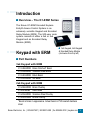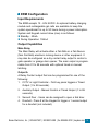
1
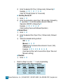
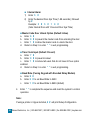
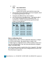
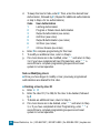
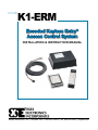
K1-ERM
○ ○ ○ ○ ○
INSTALLATION & INSTRUCTION MANUAL
Essex Electronics, Inc. | 805.684.7601 | 800.KEY-LESS | fax 805.684.0232 | keyless.com
K1-ERM Encoded Keyless Entry®
Access Control System
All rights reserved. No part of this documentation may be reproduced in any form, without prior written consent of Essex Electronics, Inc. Essex Electronics shall not be liable for errors contained in
this manual. The information in this document is subject to change
without notice. Essex Electronics, Inc. reserves the right to modify
this documentation and to make improvements or changes to the
product(s) contained in this documentation at any time.
Document Information
IOMK1-ERM Installation/Operations Manual for the K1-34-ERM3
3x4 Keypad or K1-26-ERM3 2x6 Keypad with Encoded Relay
Module (ERM) - October 2006.
This documentation is also applicable to prior revisions except
where noted.
Trademarks
Keyless Entry® is a registered trademark of Essex Electronics, Inc.
Contact Information
Essex Electronics, Incorporated
1130 Mark Avenue, Carpinteria, CA 93013
(805) 684-7601 or (800) 539-5377 (KEY-LESS)
FAX (805) 684-0232
Website: keyless.com
General email: [email protected]
Technical Support email: [email protected]
Copyright© 2006 Essex Electronics, Inc. All rights reserved.
i Essex Electronics, Inc. | 805.684.7601 | 800.KEY-LESS | fax 805.684.0232 | keyless.com
○ ○ ○ ○ ○
Table of Contents
Introduction .................................................................................. 1
Overview - The K1-ERM Series .................................................... 1
Keypad with ERM .......................................................................... 1
Part Numbers ................................................................................. 1
Specifications ................................................................................. 2
ERM Configuration ........................................................................ 3
Keypad Connector Diagram .......................................................... 5
Keypad Configuration .................................................................... 7
Normal System Operation ......................................................... 10
Keypad LED Status Indicators .................................................... 10
Tamper Alarm .............................................................................. 11
Encoded Relay Module LED Status Indicators ........................... 11
Operation Notes .......................................................................... 11
Using the K1-ERM with a PC ..................................................... 13
Connecting the K1-ERM to a PC ................................................ 13
Installing the CD-ROM ................................................................. 13
Using Keypad Programmer Software. ........................................ 14
Using Keypad Logger Software. ................................................. 15
Programming the K1-ERM with the Keypad ............................ 16
Programming Individual Users .................................................... 21
Programming the Keypad with a Hyper-terminal .................... 27
Operating Commands ................................................................. 28
K1-ERM Series Diagrams .......................................................... 29
ERM Circuit Board ....................................................................... 29
Typical Hook-up Fail Safe or Fail Secure and CCTV Diagram .. 30
Warranty & Repairs .................................................................... 32
Essex Electronics, Inc. | 805.684.7601 | 800.KEY-LESS | fax 805.684.0232 | keyless.com ii
iii Essex Electronics, Inc. | 805.684.7601 | 800.KEY-LESS | fax 805.684.0232 | keyless.com
○ ○ ○ ○
Introduction
!
Overview – The K1-ERM Series
The Essex K1-ERM Encoded Keyless
Entry® Access Control System is an
extremely versatile Keypad and Encoded
Relay Module (ERM). The 500-user code
system consists of either a 3x4 or 2x6
Keypad and an Encoded Relay
Module (ERM).
3x4 Keypad, 2x6 Keypad
& Encoded Relay Module
(clockwise from top left)
!
○ ○ ○ ○
Keypad with ERM
!
Part Numbers
3x4 Keypad with ERM
K1-34B-ERM3 Brass Finished* Bezel
K1-34S-ERM3 Stainless Steel Bezel
K1-34K-ERM3 Black Bezel
K1-34X-ERM3 No Bezel
2x6 Keypad with ERM
K1-26B-ERM3 Brass Overlay
K1-26I-ERM3 Illuminated
K1-26S-ERM3 Stainless Steel Overlay
K1-26R-ERM3 Braille Overlay
*Bezel is brass in appearance. Actual bezel is PVD-coated stainless
steel.
Essex Electronics, Inc. | 805.684.7601 | 800.KEY-LESS | fax 805.684.0232 | keyless.com 1
!
Specifications
Input Voltage:
Standby Current Draw:
Outputs:
Keypad Switch Life:
Keypad Operating Environment:
12 to 24V AC/DC
50mA (including Keypad)
3 Relay Contacts
>1 Billion Cycles
-40°C to +70°C (-40°F to +160°F),
100% Relative Humidity
3x4 Keypad Dimensions:
5-1/8"H x 3-3/8"W x 7/16"D
(13 x 8.6 x 1.1 cm)
2x6 Keypad Dimensions:
7-1/8"H x 1-3/4"W x 3/4"D
(13 x 8.6 x 1.1 cm)
3x4 Keypad Weight:
16 oz (454 gm)
2x6 Keypad Weight:
4.4 oz (125 gm)
LED's:
1 Red, 1 Green
ERM Dimensions:
5-1/2"H x 7-1/2"W x 2-1/2"D
(14 x 19.1 x 6.4 cm)
ERM Weight:
16 oz (454 gm)
Communication:
COM Port (Serial)*
*The ERM contains a serial interface to connect a computer for programming (see page 13) and reading codes or to a printer for real-time print-out
of activities.
2 Essex Electronics, Inc. | 805.684.7601 | 800.KEY-LESS | fax 805.684.0232 | keyless.com
!
ERM Configuration
Input Requirements
The ERM accepts 12 - 24V AC/DC. An optional battery charging
module and rechargeable gel cells are available to keep the
system operational for up to 50 hours during a power interruption.
System and Keypad current draw (max) is as follows:
! Standby: 50mA
! During Operation: 150mA
Output Capabilities
Main Relay
The Main Relay will activate either a Fail-Safe or a Fail-Secure
(Non Fail-Safe) electronic locking device or other equipment. It
may also be configured as a dry contact relay output to control a
gate operator or garage door opener. The main output is programmable from 01 to 99 seconds with optional timed or manual
latching.
Output A
A Relay Contact output that can be programmed for one of the
following:
1. CCTV or Light Controller - First key press triggers a Timed
Output (1 to 99 seconds).
2. Auxiliary Output - Manual Control or Timed Output (1 to 99
seconds).
3. Second Door - Users can be assigned to open a 2nd door.
4. Doorbell - Press # at the Keypad to trigger a 1 second output
for a doorbell (not included).
Essex Electronics, Inc. | 805.684.7601 | 800.KEY-LESS | fax 805.684.0232 | keyless.com 3
Output B
A Relay Contact output that can be programmed for one of the
following:
1. CCTV or Light Controller - First key press triggers a Timed
Output (1 to 99 seconds).
2. Auxiliary Output - Manual Control or Timed Output (1 to 99
seconds).
3. Third Door - Users can be assigned to open a 3rd door.
4. Internal Alarm System - Detect Break-in, Door-ajar & Tamper.
5. Doorbell - Press # at the Keypad to trigger a 1 second output
for a doorbell (not included).
4 Essex Electronics, Inc. | 805.684.7601 | 800.KEY-LESS | fax 805.684.0232 | keyless.com
!
Keypad Connector Diagram
CONFIGURATION
PINS- “CONFIG”
YELLOW- Door Monitor
(Do NOT apply voltage)
VOLTAGE SELECT
(Do NOT apply voltage)
12-24V (default)- Jumper on
one pin only
5V- Jumper on both pins
GRAY*
BLACK*- Ground
SHIELD*
ORANGE*- Program (Do NOT
apply voltage)
RED*- Input Voltage
VIOLET*
GREEN*- Output for Encoded
Relay Module (optional)
*Connect to ERM inputs.
NOTE: The 2x6 connector is rotated 180 degrees
YELLOW- Anti Tailgate
If not used, this must be connected to BLACK. By adding a door
monitor switch between YELLOW and BLACK, the door will relock
immediately after opening. If Output B is set up as Internal Alarm,
this switch will trigger the alarm if the door is opened without a
code or if the door is left open longer than the Door Ajar Time
setting.
RED, BLACK, GREEN, VIOLET, GRAY, ORANGE and SHIELDThese wires all connect to the ERM module.
Essex Electronics, Inc. | 805.684.7601 | 800.KEY-LESS | fax 805.684.0232 | keyless.com 5
TIME CLOCK
If TIME CLOCK is enabled in Set up (pages 20 and 21), when the
CLOCK terminal on the ERM circuit is connected to ground –
through time clock or other switch contacts – all codes work
normally. When the CLOCK terminal is not grounded, only those
codes with 24-hour Access Authorization (page 21) will function.
The disabled codes are still considered valid and will not trigger
Tamper Alarm if tried repeatedly.
6 Essex Electronics, Inc. | 805.684.7601 | 800.KEY-LESS | fax 805.684.0232 | keyless.com
!
Keypad Configuration
Voltage Selection
The factory default setting for the Keypad voltage is 12-24VDC.
Verify that the jumper is removed or placed over only one pin. If
changing the voltage is necessary, make sure the power is
removed first.
Keypad Output Selection
Once the voltage jumper is verified or correctly set:
1. Remove power.
2. Jumper the two pins above the connector labeled "CONFIG.”
3. Apply appropriate power. (You should hear 4 beeps and the
RED LED will flash and the GREEN LED will be solid).
4. Now that the Keypad is in configuration mode, enter 98
followed by #. You should hear 3 beeps indicating successful
configuration (the RED LED will continue to flash and the
GREEN LED will be solid). If you hear a long error beep, reenter 98 followed by #. To change the audible beep or illumination, proceed as follows. Otherwise, go to step 5.
a. To change the audible beep, enter
Code
201 #
200 #
Audible Beep
Normal Beep (factory default)
Short Click (quieter)
b. To change the illumination on the K1-26 only, enter the
code as follows:
Code
210 #
211 #
212 #
Standby Mode
Off (factory default)
Off
Off
Normal Operation
Off (factory default)
Dim
Bright
Essex Electronics, Inc. | 805.684.7601 | 800.KEY-LESS | fax 805.684.0232 | keyless.com 7
b. Code
213 #
214 #
Standby Mode Normal Operation
Dim
Dim
Dim
Bright
5. Remove power.
6. Remove configuration jumper.
7. Re-apply power.
8. Press PROGRAM button in the ERM to establish the encoded
connection. This will put the system into setup mode.
9. Press * * to exit.
IMPORTANT: Once the configuration is selected, you must remove power, remove the configuration jumper and then re-apply
power in order to complete the configuration procedure. Note: If
the configuration jumper is not removed, the LED's will flash and
the Keypad will beep continuously.
Keypad Reset
In certain cases you may want to erase all user codes and restore
system defaults. To perform this procedure:
CAUTION: This procedure completely erases the memory and
restores factory defaults! Once the memory is cleared, all programmed User Codes are erased and factory default settings
are restored.
1. Remove power.
2. Jumper the two pins above the connector labeled "CONFIG.”
3. Apply appropriate power. (You should hear 4 beeps and the
RED LED will flash and the GREEN LED will be solid).
8 Essex Electronics, Inc. | 805.684.7601 | 800.KEY-LESS | fax 805.684.0232 | keyless.com
4. Once the Keypad is in configuration mode, enter 0099#. The
Keypad will beep twice and both LEDS will flash for approximately 10 seconds. (During this time, the Keypad will appear
dead. Do NOT remove power!)
5. Enter 98 followed by #. You should hear 3 beeps indicating
successful configuration (the RED LED will continue to flash
and the GREEN LED will be solid). If you hear a long error
beep, re-enter 98 followed by #. To change the audible beep
or illumination, proceed as follows. Otherwise, go to step 6.
a. To change the audible beep, enter the code as follows:
Code
201 #
200 #
Audible Beep
Normal Beep (factory default)
Short Click (quieter)
b. To change the illumination on the K1-26 only, enter the
code as follows:
Code
210 #
211 #
212 #
213 #
214 #
Standby Mode
Off (factory default)
Off
Off
Dim
Dim
Normal Operation
Off (factory default)
Dim
Bright
Dim
Bright
6. Remove power.
7. Remove configuration jumper.
8. Re-apply power.
9. Press PROGRAM button in the ERM to establish the encoded
connection. This will put the system into setup mode.
10. Press * * to exit.
Essex Electronics, Inc. | 805.684.7601 | 800.KEY-LESS | fax 805.684.0232 | keyless.com 9
○ ○ ○ ○ ○
Normal System Operation
When the system is first powered up (or when communication is
broken between the Keypad and the ERM3 module), the PROGRAM button in the ERM must be pressed to establish the
encoded connection. This also puts the system into setup mode.
To end, press * * to exit. Or, the system will automatically exit
programming if no entries are made for 30 seconds.
!
Keypad LED Status Indicators
! A flashing green LED indicates that the door is unlocked (momentarily).
! A solid green LED indicates that the door is unlocked (latched).
! A solid red LED indicates that the door is locked.
Depending on how the System Options are configured, User
Commands are used to operate Manual Latching. The User
Commands are trailing digits entered after an authorized user
code. The ability to use these User Commands depends on
authorizations assigned to each User (see page 13 or pages 2122).
As the Main Output activates, the green LED will flash for 5
seconds. While the green LED is flashing, enter one (or more) of
the following User Commands:
0 # to Latch the Door Closed (Main Relay, 2nd Door or 3rd Door)
1 # to Latch the Door Open (Main Relay, 2nd Door or 3rd Door)
2 # to Turn Output A OFF (2nd Output as Aux.)
3 # to Turn Output A ON (2nd Output as Aux.)
4 # to Turn Output B OFF (3rd Output as1 Aux.)
5 # to Turn Output B ON (3rd Output as Aux.)
10 Essex Electronics, Inc. | 805.684.7601 | 800.KEY-LESS | fax 805.684.0232 | keyless.com
!
Tamper Alarm
An audible Tamper Alarm sounds when four incorrect code entries
are made. After 30 seconds, the unit returns to standby mode.
!
Encoded Relay Module LED Status Indicators
Mode
Normal Operation
Lockup Mode
Setup Mode
Green Red
On
Off
On
Flashing
Flashing Off
Connection Problems Off
!
On
Operation Notes
Pressing the PROGRAM button on the Encoded Relay Module
(ERM) sets a new Encode Code (EC) between the ERM and the
Keypad and puts the Keypad into Programming Mode. If no further
programming is required, press * * to exit.
If the ERM receives more than three (3) invalid EC’s in a row, the
unit will go into LockUp Mode. Once in LockUp Mode, the unit is
essentially shut down and can only be restored to normal operation by pressing the PROGRAM button.
Upon communication loss or LockUp, all relays are released and
the Main Door latching is cleared if set. The Remote Bypass will
not work and the Keypad will be forced to the non-24 hour mode if
enabled. If communication is lost for more than 2 seconds, the unit
goes into LockUp Mode and can only be restored to Normal
Operation by pressing the PROGRAM button.
Essex Electronics, Inc. | 805.684.7601 | 800.KEY-LESS | fax 805.684.0232 | keyless.com 11
If communication is lost with the ERM or the ERM is in LockUp
Mode, the Keypad will indicate the problem by flashing the Red
LED very fast.
Since the Encode Code (EC) is only sent at the beginning of a
Latch Open sequence, this is the only time the unit knows if the
EC’s match. Upon a power up, both units will communicate with
each other and the second and third relays, remote bypass and
clock input will work normally. Upon the first attempt to send an
ERM packet with a non- matching EC, the device will be put into
the LockUp mode, and from that point, until a new EC is programmed, the unit will essentially be shut down.
Pressing the PROGRAM button while the unit has lost communication can cause the EC to be erased and will require an EC setup
upon re-establishing communication. For this reason, it is recommended that the Keypad and the ERM be powered by the same
power supply so they are both powered up and down at the same
time.
Since the output is on to indicate a Non-Alarm status when using
Output B relay as an Alarm, a loss of communication or invalid EC
will always create an alarm indication.
12 Essex Electronics, Inc. | 805.684.7601 | 800.KEY-LESS | fax 805.684.0232 | keyless.com
○ ○ ○ ○
Using the K1-ERM with a PC
!
Connecting the K1-ERM to a PC
Connect the ERM to a PC using a serial cable (not included)
through the Serial COM Port. (The K1-ERM is set for 9600 baud.)
!
Installing the CD-ROM
Install the “KeypadUtils12.exe” from the enclosed CD. The files will
default to C:\Program Files\Essex\EZKey unless otherwise redirected.
Essex Electronics, Inc. | 805.684.7601 | 800.KEY-LESS | fax 805.684.0232 | keyless.com 13
!
Using Keypad Programmer Software
Program Code
Click “Set Up” and select
appropriate options and
COM Port. Click “OK.” Enter
the Keypad Master Code at
the bottom.
1. To add a code, double-click an empty line or click
and fill in the blanks.
2. To delete, highlight the code line and click
.
3. To change user options / authorizations, double-click the code
line.
When finished, save the code chart file in either protected or
unprotected format and upload
to the K1-ERM. If programming has been done at the Keypad, you can download
from
the Keypad to a blank code chart (names are not stored in the
Keypad so they will be blank) or MERGE
the Keypad information with an existing code chart. If there are conflicts (e.g., two
User Number 1’s), you will be asked to select a resolution. Once
complete, you will need to save the chart and upload to the
Keypad to make sure they both agree.
14 Essex Electronics, Inc. | 805.684.7601 | 800.KEY-LESS | fax 805.684.0232 | keyless.com
Temporary Code
You can program one temporary code that will be good for up to
99 hours 59 minutes.
Configuration
You can GET the configuration that is in the Keypad or make your
own, then SET it into the Keypad.
!
Using Keypad Logger Software
Running this log will record all actions of the K1-ERM. You can
also print up to the last 500 transactions. The date and times are
taken from the computer, not the K1-ERM.
Set up
If BIND is blank, the log will only list the User Number along with
the action. If you BIND to an existing Keypad Program File (see
previous section), the user name will also be listed.
Select “Options” and “COM Port.”
Alarms
Loss of power- reported when power is restored.
Tamper Alarm- 4 incorrect code entries
Loss of communication between Keypad and ERM (Keypad
removed or broken connection).
Essex Electronics, Inc. | 805.684.7601 | 800.KEY-LESS | fax 805.684.0232 | keyless.com 15
○ ○ ○ ○ ○
Programming the K1-ERM
with the Keypad
To set up and program the system using the
Keypad, proceed as follows. The System
Setup can only be modified if you know the
Master Code. When the system is initially set
up, the default system settings should be
reviewed prior to other programming.
1. Enter * 3
2. Enter the Master Code followed by #
Example: * 3 1 2 3 #
This opens programming and causes:
Red LED Green LED
Fast Flash Solid
3. Proceed to one of the following eight programming options:
! Changing the Master Code (Default: 1,2,3)
a. Enter 1 #
b. Enter the New Master Code followed by #
c. Return to Step 3 or enter * * to exit programming.
Keypad Status After Step Completion
Step
Beep Red LED
Green LED
a
Double Fast Flash Slow Flash
b
Triple Fast Flash Solid
Note: If you forget the Master Code, locate and press the PROGRAM
button on the ERM board. This will take you to Step 3 of Programming
System Setup. Once you enter setup mode, you have 30 seconds to
begin the program sequence.
16 Essex Electronics, Inc. | 805.684.7601 | 800.KEY-LESS | fax 805.684.0232 | keyless.com
! Setting the Main Door Open Time (Default: 5 Seconds)
a. Enter 2 #
b. Enter the desired Door Open Time (1-99 seconds), followed by #
Example: 2 # 1 5 # (15 sec. Door Open Time)
c. Return to Setp 3 or enter * * to exit programming.
Keypad Status After Step Completion
Step
Beep Red LED
Green LED
a
Double Slow Flash Slow Flash
b
Triple Slow Flash Solid
Setting Latching Option (Default: Off)
a. Enter 3 #
b. Select the desired latching option:
Off- 0 #
Manual- 9 9 #
Timed- Enter the desired time interval in hours (1-98), followed
by #.
Example: 3 # 8 # (Sets timed latching for 8 hrs)
c. Return to Step 3 or enter * * to exit programming.
Keypad Status After Step Completion
Step
Beep Red LED
Green LED
a
Double Slow Flash Slow Flash
b
Triple Slow Flash Solid
!
Configuring Output A (Default: Aux #1)
a. Enter 4 #
b. Select one of the following:
! CCTV / External Light
1) Enter 1 #
!
Essex Electronics, Inc. | 805.684.7601 | 800.KEY-LESS | fax 805.684.0232 | keyless.com 17
2) Enter the desired On Time (1-99 seconds), followed by #
Example: 4 # 1 # 1 5 #
(Sets CCTV/Light Option for 15 seconds)
! Auxiliary Device #1
1) Enter 2 #
2) Enter the momentary output time (1-99 seconds), followed by
# ; -or- Enter 0 to set the auxiliary device for Manual
Operation (ON/OFF), followed by #
Example: 4 # 2 # 0 #
(Sets Auxiliary Device with Manual Operation)
! Second Door
1) Enter 3 #
2) Enter the desired Door Open Time (1-99 seconds), followed
by #
3) Select the desired latching method:
Off- 0 #
Manual- 9 9 #
Timed- Enter the desired time interval in hours (1-98),
followed by #
Example: 4 # 3 # 5 # 9 9 #
(Sets Second Door with 5 second Door Open Time and
Manual Latching)
! Doorbell
1) Enter 4 #
c.
Return to Step 3 or enter * * to exit programming.
Keypad Status After Step Completion
Step
Beep Red LED
Green LED
a
Double Slow Flash Slow Flash
1)
Double Slow Flash Fast Flash
2)
Triple Slow Flash Solid
18 Essex Electronics, Inc. | 805.684.7601 | 800.KEY-LESS | fax 805.684.0232 | keyless.com
Configuring Output B (Default: CCTV)
a. Enter 5 #
b. Select one of the following:
! CCTV / External Light
1) Enter 1 #
2) Enter the desired On Time (1-99 seconds), followed by #
Example: 5 # 1 # 1 5 #
(Sets CCTV/Light Option for 15 seconds)
! Auxiliary Device #2
1) Enter 2 #
2) Enter the momentary output time (1-99 seconds), followed by
#; -or- Enter 0 to set the auxiliary device for Manual
Operation (ON/OFF), followed by #
Example: 5 # 2 # 0 #
(Sets Auxiliary Device with Manual Operation)
! Third Door
1) Enter 3 #
2) Enter the desired Door Open Time (1-99 seconds), followed
by #
3) Select the desired latching method:
Off- 0 #
Manual- 9 9 #
Timed- Enter the desired time interval in hours (1-98),
followed by #
Example: 5 # 3 # 5 # 9 9 #
(Sets Second Door with 5 second Door Open Time and
Manual Latching)
! Doorbell
1) Enter 4 #
!
Essex Electronics, Inc. | 805.684.7601 | 800.KEY-LESS | fax 805.684.0232 | keyless.com 19
! Internal Alarm
1) Enter 5 #
2) Enter the desired Door Ajar Time (1-99 seconds), followed
by #
Example: 5 # 5 # 1 0 #
(Sets Internal Door with 10 second Door Ajar Time)
! Master Code Door Unlock Option (Default: Allow)
a.
b.
c.
d.
Enter 6 #
Enter 0 # to prevent the master code from unlocking the door.
Enter 1 # to allow the master code to unlock the door.
Return to Step 3 or enter * * to exit programming.
! Time Clock Input (Default: Prevent)
a. Enter 7 #
b. Enter 0 # to prevent lockout
c. Enter 1 # to lockout all users that do not have 24 hour option
enabled.
d. Return to Step 3 or enter * * to exit programming.
! Baud Rate (if using Keypad with Encoded Relay Module)
a. Enter 8 #
b. Enter 0 # to set Baud Rate to 2400
c. Enter 1 # to set Baud Rate to 9600 (default)
4. Enter * * to complete the sequence and reset the system to normal
operation.
Note:
If using a printer or Hyper-terminal, 0 # will print Setup Configuration
20 Essex Electronics, Inc. | 805.684.7601 | 800.KEY-LESS | fax 805.684.0232 | keyless.com
! Programming
Individual Users
Authorized users (master code or any user
authorized to program) can program users
directly from the Keypad. Each Individual
User can be assigned various authorizations.
Review System Setup before programming
individual users.
1. Enter * 1
2. Enter the Master Code followed by #
Example: * 1 1 2 3 #
This opens programming and causes:
Red LED
Slow Flash
Green LED
Solid
3. Proceed to one of the following seven programming options:
! Adding a New User
a. Enter 1 #
b. Enter the User ID (1 to 499) followed by #
c. Enter the User Code/PIN (3-8 digits), followed by #
d. Enter the desired User Authorization Code, followed by # (Repeat
for additional authorizations or skip to Step e for no authorizations.)
Code User Authorization
1
Latching Authorization
2
Program or Delete Users Authorization
3
Output A Authorization (see notes)
4
2nd Door (see notes)
5
Output B Authorization (see notes)
6-7
Continued on next page
Essex Electronics, Inc. | 805.684.7601 | 800.KEY-LESS | fax 805.684.0232 | keyless.com 21
d. cont’d.
Code User Authorization
6
3rd Door (see notes)
7
Exempt from Security Level restrictions (see notes)
e. Once all desired User Authorizations have been assigned, enter #
to complete programming for this User.
f. To program an additional User, return to Step b.
g. If no more Users are to be added, enter * * and return to Step 3,
or if you have completed all User Programming, enter * * a
second time to complete programming sequence and reset
system to normal operation.
Keypad Status After Step Completion
Step Beep
Red LED
Green LED
a
Double Slow Flash Slow Flash
b
Double Slow Flash Fast Flash
c
Double Slow Flash Fast Flash
d
Double Slow Flash Fast Flash
e
Double Slow Flash Fast Flash
f
Triple
Slow Flash Slow Flash
Notes on Adding New Users:
! Auxiliary Device or 2nd or 3rd Door authorization depends on configuration of the A and B Outputs. See System Setup on pages 16-20.
! If either Output is configured for 2nd or 3rd Door operation and a user is
given 4# or 6# Authorization, their User Code will activate the configured
output, not the Main Relay.
! 24 Hour Access requires an external time clock or keyswitch. This allows
you to restrict access to Users who are not assigned 24-hour Access. See
Time Clock Input on pages 5-6.
22 Essex Electronics, Inc. | 805.684.7601 | 800.KEY-LESS | fax 805.684.0232 | keyless.com
! Modify a User by User ID
a. Enter 2 #
b. Enter the User ID (1 to 499) for the User to be modified, followed
by #
c. To change this User’s Code, enter the New User Code followed
by #
d. To keep this User’s Code, enter #. Then, enter the desired User
Authroization, followed by #. (Repeat for additional authorizations
or skip to Step e for no authorizations.)
Code User Authorization
1
Latching Authorization
2
Program or Delete Users Authorization
3
Output A Authorization (see notes)
4
2nd Door (see notes)
5
Output B Authorization (see notes)
6
3rd Door (see notes)
7
24-hour Access (see notes)
e. Enter # to complete programming for this User.
f. To modify an additional User, return to Step b.
g. If no more Users are to be modified, enter ∗ ∗ and return to
Step 3, or if you have completed all User Programming, enter
∗ ∗ a second time to complete programming sequence and
reset system to normal operation.
Modify a User by User Code
a. Enter 3 #
b. Enter the User Code for the User you wish to modify, followed
by #
c. To change this User’s Code, enter the New User Code followed
by #
!
Essex Electronics, Inc. | 805.684.7601 | 800.KEY-LESS | fax 805.684.0232 | keyless.com 23
d. To keep this User’s Code, enter #. Then, enter the desired User
Authorization, followed by #. (Repeat for additional authorizations
or skip to Step e for no authorizations.)
Code User Authorization
1
Latching Authorization
2
Program or Delete Users Authorization
3
Output A Authorization (see notes)
4
2nd Door (see notes)
5
Output B Authorization (see notes)
6
3rd Door (see notes)
7
24-hour Access (see notes)
e. Enter # to complete programming for this User.
f. To modify an additional User, return to Step b.
g. If no more Users are to be modified, enter * * and return to Step
3 or if you have completed all User Programming, enter * * a
second time to complete programming sequence and reset
system to normal operation.
Note on Modifying Users:
! Once you have begun to modify a User, previously programmed
authorizations are deleted for this User.
! Deleting a User by User ID
a. Enter 4 #
b. Enter the User ID (1 to 499) for the User to be deleted, followed
by #
c. To delete an additional User, return to Step b.
d. If no more Users are to be deleted, enter * * and return to Step
3, or if you have completed all User Programming, enter * * a
second time to complete programming sequence and reset
system to normal operation.
24 Essex Electronics, Inc. | 805.684.7601 | 800.KEY-LESS | fax 805.684.0232 | keyless.com
! Deleting a User by User Code
a.
b.
c.
d.
Enter 5 #
Enter the User Code to be deleted, followed by #
To delete an additional User, return to Step b.
If no more Users are to be deleted, enter * * and return to Step
3, or if you have completed all User Programming, enter * * a
second time to complete programming sequence and reset
system to normal operation.
! Adding a Temporary User
a. Enter 6 #
b. Enter the User Code / PIN (3-8 digits), followed by #
c. Enter the desired Temporary access Time (1-99 hours), followed
by #
d. For 24-hour Access, enter 0 for No or 1 for Yes, followed by #
e. Enter * * and return to Step 3, or if you have completed all User
Programming, enter * * a second time to complete programming
sequence and reset system to normal operation.
! Deleting a Temporary User
a. Enter 7 #
b. Enter * * and return to Step 3, or if you have completed all User
Programming, enter * * a second time to complete programming
sequence and reset system to normal operation.
4. Enter * * to complete the sequence and reset the system to normal
operation.
Essex Electronics, Inc. | 805.684.7601 | 800.KEY-LESS | fax 805.684.0232 | keyless.com 25
Notes:
If using a printer or Hyper-terminal, 0 # will print all User ID’s, Codes and
Authorizations.
Once an authorized user completes steps 1 & 2 to open the memory, any
combination of adding, modifying or deleting Users can be performed
without having to re-enter Steps 1 & 2 each time. However, if more than 30
seconds elapse between each step during programming, the system will
reset and you will have to start from Step 1.
26 Essex Electronics, Inc. | 805.684.7601 | 800.KEY-LESS | fax 805.684.0232 | keyless.com
○ ○ ○ ○ ○
Programming the Keypad with a
Hyper-terminal
1. Set up the Hyper-terminal with the following options:
!
!
!
!
!
!
!
!
9600 Baud (This is required for the program to work.)
8 Data Bits
No Parity
1 Stop Bit
No Flow Control
Send line ends with line feeds
Echo-typed chars locally
Backspace key sends CTRL+H, SPACE, CTRL+H
2. Connect the ERM Module to the serial port.
3. To Log In, the Keypad must NOT be in the following modes:
Setup, Programming, or Door Input Active.
4. Once logged in, the Keypad will not function until the user
exits the program.
Notes:
! If there is no activity for 60 seconds, the unit will time out and
return to Normal Operation.
! While in Program mode, both LED’s blink fast.
! If 4 invalid Master Codes are entered, the unit will go into
Tamper mode.
! If you have set the Hyper-terminal to send CTRL+H, SPACE,
CTRL+H for backspace, the backspace key will work correctly.
!
All commands are case insensitive.
Essex Electronics, Inc. | 805.684.7601 | 800.KEY-LESS | fax 805.684.0232 | keyless.com 27
!
Operating Commands
To
Type
Log in
login, MASTERCODE
Insert a User
in, USER, PIN [,OPTIONS]*
Modify a User
mo, USER, PIN [,OPTIONS]*
Delete a User
de, USER
Insert the Temp Code
in, tmp, PIN, EXPTIME [,OPTIONS]*
Modify the Temp Code
mo, tmp, PIN, EXPTIME [,OPTIONS]*
Delete the Temp Code
de, tmp
List a User
le, USER (or “tmp” for Temp Code)
List all Users
la
List all Users paged
lp
List Keypad configuration
lc
Exit program
ex
*[,OPTIONS]= option numbers with no commas between them.
Example: Type mo,5,555,13 to change User 5 code to 555 and give
Latching and Output A authorization.
28 Essex Electronics, Inc. | 805.684.7601 | 800.KEY-LESS | fax 805.684.0232 | keyless.com
○ ○ ○ ○ ○
K1-ERM Series Diagrams
ERM Circuit Board
2
!
Essex Electronics, Inc. | 805.684.7601 | 800.KEY-LESS | fax 805.684.0232 | keyless.com 29
Typical Hook-up Fail Safe or Fail Secure and
CCTV Diagram
!
30 Essex Electronics, Inc. | 805.684.7601 | 800.KEY-LESS | fax 805.684.0232 | keyless.com
○ ○ ○ ○
Notes
Essex Electronics, Inc. | 805.684.7601 | 800.KEY-LESS | fax 805.684.0232 | keyless.com 31
○ ○ ○ ○ ○
Warranty & Repairs
!
Limited Lifetime Warranty
(effective date May 1, 2006)
Essex Electronics Inc. warrants that at the time of original
purchase from Essex Electronics Inc., the products specified below
are free from defects in workmanship and material. Subject to the
conditions and limitations set forth below, Essex Electronics Inc.
will, at its option, either repair or replace any part of its products
that prove defective by reason of improper workmanship or
materials. Repaired parts or replacement products will be provided
by Essex Electronics Inc. on an exchange basis, and will be either
new or refurbished to be functionally equivalent to new. Essex
Electronics Inc. reserves the right to discontinue a product for any
reason, without notice, at any time. If a product that has been
discontinued proves defective and if Essex Electronics Inc. is
unable to repair or replace the product, within the terms expressed
in this Limited Lifetime Warranty, a substitute product may be
provided at the Essex Electronics Inc.’s election, as a replacement
for the original discontinued product.
This Limited Lifetime Warranty extends only to the original retail or
wholesale Buyer and the original site of installation. It does not
cover any damage to this product or parts thereof, if the product is
installed in violation of the applicable codes or ordinances, or is
not installed in accordance with our installation instructions. This
warranty will only include the normal operating life of the LED’s
which will be 10 years from the date of the original sale. It does not
cover any damage that results from accident, abuse, misuse,
natural disaster, insufficient or excessive electrical supply, abnormal mechanical or environmental conditions, or any unauthorized
disassembly, repair, or modification. This Limited Lifetime Warranty
32 Essex Electronics, Inc. | 805.684.7601 | 800.KEY-LESS | fax 805.684.0232 | keyless.com
also does not apply to any product on which the original identification or date of manufacture information has been altered, obliterated or removed. In no event shall Essex Electronics Inc. be liable
for any damage to persons, property or area surrounding the
installation site caused by any malfunction of the product manufactured by Essex Electronics Inc.
Essex Electronics Inc. will not pay, nor be responsible for, shipping,
transportation or delivery charges, or other cost of removal of a
defective product or installation of a replacement product. The
original component replaced under this Limited Lifetime Warranty
in any system shall become the property of Essex Electronics Inc.,
and as such will, at our request, be returned to our factory with
transportation charges paid by the Buyer.
Limited Lifetime Warranty
The Essex Electronics Inc. products with a manufactured date of 5/
1/06 to the present date that are covered by this Limited Lifetime
Warranty are Keypads, Keyless Entry Access Control Systems and
accessories.
Essex Electronics, Inc.’s liability and Buyer’s remedy under this
warranty is limited to the repair or replacement at Seller’s election
of the product, or parts thereof, returned to Essex Electronics Inc.
at Buyer’s expense and shown to Essex Electronics Inc.’s reasonable satisfaction to have been defective.
Notice of any defect must be sent to Essex Electronics, Inc., 1130
Mark Avenue, Carpinteria, California, 93013, USA and must
include the date code of the unit, description of the defect and
factory assigned Return Authorization #. Upon receipt of such
notification, Essex will determine whether to repair or replace. We
also reserve the right to have our representative make any inspection or repairs, or furnish replacements.
Essex Electronics, Inc. | 805.684.7601 | 800.KEY-LESS | fax 805.684.0232 | keyless.com 33
This warranty excludes Elevator and Vehicle Keyless Entry Access
Control Systems. A separate warranty applies to Keyless Entry
systems manufactured for these applications.
Disclaimer of Warranties: Limitation of Buyer’s Remedies
Except for the repair or replacement at seller’s option which is
expressly set forth above, Essex Electronics Inc. extends no
warranty of any kind, express or implied, and disclaims any implied
warranty of merchantability or suitability for purpose for which sold,
with respect to the keypads, keyless entry coded access system or
accessories. Except for the limited repair or replacement specified
above, under no circumstances will Essex Electronics Inc. be
liable to buyer under or in connection with any manufacture or sale
of any of the products set forth above under any tort, negligence,
strict liability, contract or other legal or equitable theory, or for
incidental or consequential damages, or buyer’s cost of effecting
insurance coverage.
The foregoing limited lifetime warranty expressed herein constitutes the sole and entire warranty with respect to the products set
forth above and is in place of any and all other warranties, express
or implied.
This warranty may not be expanded or extended by any oral
representation, written sales information, advertising, drawings or
otherwise. Essex Electronics Inc. is not responsible hereunder for
incidental damage to person or property, or other incidental or
consequential damages. The remedies of the buyer shall be
limited to those provided in this limited lifetime warranty to the
exclusion of any and all other remedies, including, without limitation, incidental or consequential damages.
34 Essex Electronics, Inc. | 805.684.7601 | 800.KEY-LESS | fax 805.684.0232 | keyless.com
This Limited Lifetime Warranty shall be governed by and interpreted in accordance with the California Uniform Commercial Code
and by the procedural laws of the State of California. Any lawsuit or
other action which arises out of, relates to, or is in connection with
the manufacture or sale of the products set forth above shall be
governed by California law, and the venue for any such action shall
be the Superior Court of the State of California in and for Santa
Barbara County, California.
! Repair
Policy
Should it be necessary for a component or a system to be returned
for repair, it must be accompanied with an RA# (Return Authorization Number) issued by the factory. Please call 1-800-KEYLESS
(800-539-5377) to obtain an RA#. All returns must be sent to the
factory freight prepaid. Collect shipments will not be accepted at
any time. Standard turnaround time is ten (10) working days from
the date of receipt. Repaired components will be returned UPS
Ground (or equivalent). Any other shipping requests or instructions
will be at the customer’s expense.
At the factory’s discretion, warranty repairs will include repair or
replacement, update and testing. Returns and repairs out of the
warranty period or in warranty with damage not covered under
warranty shall be subject to a repair charge. All non-warranty repair
freight charges are paid for by the customer. Non-warranty repair
charges are returned COD. (Factory Authorized Distributors are
subject to standard terms).
Essex Electronics, Inc. | 805.684.7601 | 800.KEY-LESS | fax 805.684.0232 | keyless.com 35
○ ○ ○ ○ ○
Essex Electronics, Inc. | 805.684.7601 | 800.KEY-LESS | fax 805.684.0232 | keyless.com