1
Zoom XLo
Owner/Operator Manual
Manuel Du Proprietaire/Utilisateur
Models
915145 - Zoom XL 42
915147 - Zoom XL 48
915149 - Zoom XL 54
ENGLISH
04040800
FRAN(_AIS
10/09
Printed in USA
SAFETY ..........................
ASSEMBLY
......................
CONTROLS
AND FEATURES
OPERATION
.......
.....................
MAINTENANCE
SERVICE
4
SCHEDULE
........
AND ADJUSTMENTS
.....
STORAGE .......................
10
TROUBLESHOOTING
11
SERVICE
12
ACCESSORIES
16
SPECIFICATIONS
17
WARRANTY
25
.............
PARTS .................
...................
.................
.....................
26
28
28
29
30
II _/ d-'{o]_ll_o,]_o) _I
NON-ENGLISH
MANUALS
THE MANUAL
Manuals in languages other than
English Visit
may your
be obtained
from your
Dealer.
dealer or
www.ariens.com for a list of
Before operation of unit, carefully and
completely read your manuals. The contents
will provide you with an understanding of
safety instructions and controls during normal
operation and maintenance.
equipment.
languages available for your
Manuals printed in languages other
than English are also available as a
free download on our website:
All reference to left, right, front, or rear are
given from operator seated in operation
position and facing the direction of forward
travel.
htt p://www.ariens.co
MODEL AND SERIAL NUMBERS
m
MANUALES EN IDIOMAS
DIFERENTES DEL INGLES
Puede obtener manuales en
idiomas diferentes del ingles en su
distribuidor. Visite a su distribuidor
o vaya a www.ariens.com para
obtener una lista de idiomas
disponibles para su equipo.
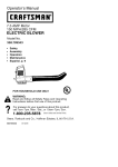
When ordering replacement parts or making
service inquiries, know the Model and Serial
numbers of your unit and engine.
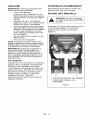
Numbers are located on the product
registration form in the unit literature
package.
They are printed on a serial number label,
located on the frame of your unit (figure 1).
Tambien puede imprimir manuales
en idiomas diferentes del ingles
descargandolos gratuitamente de
nuestra pagina Web:
htt p://www.ariens.co
m
Manuels non anglais
Des manuels dans differentes
,_
votre revendeur.
langues
sont disponibles
Rendez-vous
chez
chez votre revendeur ou allez sur
consulter la liste des langues
le site www.ariens.com pour
disponibles pour votre equipement.
1.
2.
Les manuels imprimes dans des
langues differentes de I'anglais
sont egalement disponibles en
telechargement gratuit sur notre
site Web:
htt p://www.ariens.co
Unit Serial Number Label
Engine Serial Number Label
Figure 1
m
GB-2
Record
UnitModel
andSerial
numbers DELIVERY
here.
Customer Note:
If you have purchased this
product without complete assembly and
instruction by your retailer, it is your
responsibility to:
Record
Engine
Model
andSerial
numbers
here.
Read and understand all assembly
instructions in this manual. If you do not
understand or have difficulty following
the instructions, contact your nearest
Ariens Dealer for assistance.
PRODUCT REGISTRATION
The Ariens dealer must register the product
at the time of purchase. Registering the
product will help the company process
warranty claims or contact you with the latest
service information. All claims meeting
requirements during the limited warranty
period will be honored, whether or not the
product registration card is returned. Keep a
proof of purchase if you do not register your
unit.
Customer Note: If the dealer does not
register your product, please fill out, sign, and
return the product registration card to Ariens.
UNAUTHORIZED
PARTS
REPLACEMENT
Use only Ariens replacement parts. The
replacement of any part on this unit with
anything other than an Ariens authorized
replacement part may adversely affect the
performance, durability, and safety of this unit
and may void the warranty. Ariens disclaims
liability for any claims or damages, whether
warranty, property damage, personal injury or
death arising out of the use of unauthorized
replacement parts.
NOTE: To locate your nearest Ariens Dealer,
go to www.ariens.com on the internet.
,_
adjustments Improper
WARNING:
can causeassembly
serious or
injury.
Before Attempting To Operate Your
Unit:
1. Make sure all assembly has been
properly completed.
2. Understand all Safety Precautions
provided in the manuals.
3. Review control functions and operation
of the unit. Do not operate the unit
unless all controls function as described
in this manual.
4. Review recommended lubrication,
maintenance and adjustments.
5. Review Limited Warranty Policy.
6. Fill out a product registration card and
return the card to the Ariens Company or
go to www.ariens.com.
DISCLAIMER
Ariens reserves the right to discontinue,
change, and improve its products at any time
without notice or obligation to the purchaser.
The descriptions and specifications contained
in this manual were in effect at printing.
Equipment described within this manual may
be optional. Some illustrations may not be
applicable to your unit.
GB-3
[,='Y-,1
_1=11"4
WARNING: This cutting machine
is capable of amputating hands
and feet and throwing objects.
Failure to observe the safety
instructions in the manuals and on
decals could result in serious injury
or death.
HAZARDOUS
SITUATION! If not
DANGER: IMMINENTLY
avoided, WILL RESULT in death or
serious injury.
_
Slopes are a major factor related
to loss-of-control and tip-over
accidents. Operation on all slopes
requires extra caution.
Tragic accidents can occur if the
operator is not alert to the
presence of children. Never
assume that children will remain
HAZARDOUS
SITUATION! If not
WARNING: POTENTIALLY
avoided, COULD RESULT in
death or serious injury.
CAUTION: POTENTIALLY
HAZARDOUS SITUATION! If not
avoided, MAY RESULT in minor or
moderate injury. It may also be
used to alert against unsafe
practices.
where you last saw them.
Gasoline is extremely flammable
and the vapors are explosive,
handle with care.
NOTATIONS
NOTE: General reference information for
proper operation and maintenance practices.
Disengage attachment, stop unit
and engine, remove key, engage
parking brake, and allow moving
parts to stop before leaving
operator's position.
IMPORTANT: Specific procedures or
information required to prevent damage to
unit or attachment.
SAFETY DECALS AND
LOCATIONS
SAFETY ALERTS
Look for these symbols to point
out important safety
precautions. They mean:
Attention!
Involved!
Personal Safety Is
Become Alert!
Obey The Message!
The safety alert symbol is used in decals and
with this manual. Understand the safety
message. It contains important information
about personal safety.
GB-4
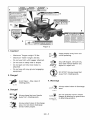
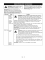
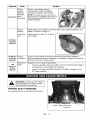
ALWAYS replace missing or damaged Safety
Decals. Refer to figure 2 for Safety Decal
locations.
7
6
5
Figure
2
1. Caution!
®
•
Maximum Tongue weight: 30 Ibs.
•
Maximum Trailer weight: 300 Ibs.
•
Do not use hitch with bagger attached.
•
Do not use on steep hills or slopes.
•
Do not park on hills when trailer is
attached.
•
Do not use with any ground engaging
equipment.
Keep people away from unit
while operating.
Shut off engine, remove key,
and read manual before you
adjust or repair unit.
©L1812
NO STEP! Always keep feet
away from rotating parts.
2. Danger!
OL1813
J_
4. Warning!
_p
Avoid
rotatinginjury
parts.- Stay clear of
OL1816
Always stand clear of discharge
area.
3. Danger!
©L1814
Do not operate mower unless
bagger is attached or guards are
in operating position.
Always keep feet and hands
away from rotating parts.
OL1809
0LI815
Always stand clear of discharge
area. Do not direct discharge
toward other people.
GB-5
5. Danger! To Avoid Serious Injury or
Death
[]]
Read the operator's
6. Hot Surfaces!
manual.
OL1801
DO NOT touch parts which are
hot from operation. ALWAYS
allow parts to cool.
OL1801
7. Caution!
Q
Keep children and others away
from unit while operating.
OL1802
No smoking.
OL1803
Never direct discharge toward
other people. Thrown objects
can cause injury.
iD.
(ram)
Look down and behind before
and while backing.
0[-1804
Fill fuel tanks to 2-1/2 in.
(6.35 cm) below bottom of filler
neck.
Never fill fuel tank when engine is
running, hot or unit is indoors. Never
overfill fuel tank.
Replace fuel cap securely and clean up
spilled fuel.
Never carry children.
8. Danger!
OL1806
Go up and down slopes, not
OL1807
Keep hands and feet away.
across.
DO NOT operate on slopes over
10°.
•
If machine stops going uphill, stop
blade and back down slowly.
|,_
Do not operate mower unless
guards are in operating position
•
Avoid sudden turns.
_--_']_j
or bagger is attached.
•
Keep safety devices (guards, shields,
switches, etc.) in place and working.
•
Check interlock system per manual
before use.
•
Understand location and function of all
controls.
Emission Control System
Certification
Label
Never allow operation by untrained
persons.
Disengage PTO, stop unit and engine,
set parking brake and remove key
before making any inspections, repairs,
etc.
Tampering with emission controls and
components by unauthorized personnel may
result in severe fines or penalties. Emission
controls and components can only be
adjusted by EPA and!or CARB authorized
service centers. Contact your Ariens
Equipment Retailer concerning emission
controls and component questions.
SAFETY RULES
If unit is to be used by someone other than
original purchaser; loaned, rented or sold,
ALWAYS provide this manual and any
needed safety training before operation.
GB-6
Only
theusercanprevent
andisresponsibleProtect
eyes,
faceandhead
fromobjects
that
foraccidents
orinjuries
occurring
to
maybethrown
fromunit.Wear
appropriate
themselves,
other
people
orproperty.
hearing
protection.
Always
wear
safety
goggles
orsafety
glasses
withsideshields
Read,
understand,
andfollow
allsafety
operating
mower.
practices
inOwner/Operator
Manual
before when
assembling,
using
orworking
onthismower. Avoid
sharp
edges.
Sharp
edges
cancut.
parts
cancutofffingers
orahand.
ALWAYS
remove
keyfromignition
andwire Moving
fromspark
plugbefore
assembly,
orworking ALWAYS
keep
hands
andfeetaway
fromall
onthisunit.
rotating
parts
during
operation.
Rotating
parts
parts.
Inspect
unitbefore
each
usefor:missing
or cancutoffbody
damaged
decals
andshields,
correctly
ALWAYS
keep
hands
away
fromallpinch
operating
safety
interlock
system,
and
points.
deterioration
ofgrass
catchers.
Replace
or
Start
andoperate
unitonly
when
seated
in
repair
asneeded.
operator's
position.
Steering
control
levers
ALWAYS
check
overhead
andside
must
beinneutral,
PTO
disengaged
and
clearances
carefully
before
operation.
parking
brake
setwhen
starting
engine.
ALWAYS
beaware
oftraffic
when
crossing
or ALWAYS
keep
body
andhands
away
from
operating
along
streets
orcurbs.
pinholes
ornozzles
which
eject
hydraulic
Keep
children,
people,
andpetsaway.
Be
fluidunder
pressure.
alertandshutoffunitifanyone
enters
work DONOT
touch
unitparts
which
might
behot
area.
Keep
children
under
watchful
careofa from
operation.
Allow
parts
tocoolbefore
responsible
adult.
attempting
tomaintain,
adjust
orservice.
NEVER
allow
children
tooperate
orplayon NEVER
place
y
our
hands
orany
partofyour
ornear
unit.
body
orclothing
inside
ornear
anymoving
Keep
area
ofoperation
clear
ofalltoys,and partwhile
unitisrunning.
debris.
Thrown
objects
cancause
injury.
NEVER
direct
discharge
towards
persons
or
Stay
alertforhidden
hazards,
holes,
andruts. property.
Thrown
objects
mayricochet
back
towards
operator.
ALWAYS
stand
clear
ofthe
Avoid
uneven
orrough
terrain.
DONOT
discharge
area.
operate
near
drop-offs,
ditches,
or
embankments.
Unitcansuddenly
turnoverif ALWAYS
disengage
attachment,
stopunit
awheel
isovertheedge
ofaclifforditch,
orif andengine,
remove
key,
engage
parking
anedge
caves
in.
brake,
andallow
moving
parts
tostopbefore
operator's
position.
Dust,
fog,etc.canreduce
vision
andcause leaving
anaccident.
Operate
unitonlywhen
there
is Useextreme
caution
ongravel
surfaces.
good
visibility
andlight.
Disengage
PTO
when
attachment
isnotin
Data
indicates
thatoperators,
age60and
useandwhen
crossing
gravel
surfaces.
above,
areinvolved
inalarger
percentage
of DONOT
operate
unitifsafety
interlock
riding
mower
related
injuries.
These
system
isdamaged
ordisabled.
Check
safety
operators
should
evaluate
their
ability
to
interlock
before
each
use.
operate
theriding
mower
safely
enough
to
remove
keytoprevent
unauthorized
protect
themselves
andothers
from
serious ALWAYS
use.
injury.
DO NOT operate at too fast a rate. Slow
Wear
adequate
safety
gear,
sturdy
shoes, down
before turning.
andprotective
gloves.
Stop engine before removing grass catcher or
Only
trained
adults
mayoperate
unit.Trainingunclogging chute.
includes
being
familiar
withcontrols
and
DO NOT mow on wet grass. Reduced
actual
operation.
traction could cause sliding.
NEVER
operate
unitafter
orduring
theuseof DO NOT mow with the deck access plate
medication,
drugs
oralcohol.
open. Always make sure the access plate is
NEVER
allow
anyone
tooperate
thisunit
down, or secured down, with the hardware.
when
their
alertness
orcoordination
is
DO NOT try to stabilize the machine by
impaired.
putting your foot on the ground.
DONOT
wear
loose
clothing
orjewelry
and Know the weight of loads. Limit loads to those
tieback
hairthatmaygetcaught
inrotating you
can safely control and the unit can safely
parts.
handle.
GB-7
ALWAYS
keep
protective
structures,
guards DO NOT transport machine while engine is
andpanels
ingood
repair,
inplace
and
running.
securely
fastened.
ALWAYS turn off power to attachment and
Donotoperate
without
either
entire
grass shut off fuel when transporting unit.
catcher
orthedischarge
guard
inplace.
Keep unit free of grass clippings, leaves, and
DONOT
operate
inreverse
unless
absolutelyother debris. Clean up oil or fuel spills.
necessary.
ALWAYS
lookdown
andbehind This product is equipped with an internal
before
andwhile
backing;
especially
for
combustion type engine. DO NOT use unit on
children.
or near any unimproved, forest-covered or
Follow
themanufacturer's
recommendations
brush covered land unless exhaust system is
forwheel
weights
orcounterweights
to
equipped with a spark arrester meeting
improve
stability
when
using
attachments. applicable local, state or federal laws. A spark
NEVER
carry
passengers-especially arrester, if it is used, must be maintained in
effective working order by operator.
children-even
withblades
off.
Fuel is highly flammable and its vapors are
Useextra
care
when
approaching
blind
corners
orobjects
thatmayobscure
vision
of explosive. Handle with care. Use an
approved fuel container.
hidden
obstacles
andchildren.
NO smoking, NO sparks, NO flames.
Ifyoucannot
back
upaslope
oryoufeel
ALWAYS allow engine to cool before
uneasy
onit,donotmow
it.
Mow
upanddown
slopes,
notacross
them. servicing.
fill fuel tank when engine is running
Useslowspeed
onanyslope.
Tires
maylose orNEVER
hot from operation.
traction
onslopes
even
though
thebrakes
are NEVER
fill or drain fuel tank indoors.
functioning
properly.
NEVER overfill fuel tank.
Keep
allmovements
ontheslope
slow and
gradual, DO NOT make sudden changes in
speed or direction.
Use extra care while operating machines with
grass catcher or other attachments. They can
affect stability of the machine.
Avoid starting, stopping, or turning on a
slope. If tires lose traction, disengage the
blades and proceed slowly straight down the
slope.
DO NOT operate on slopes over 10° .
DO NOT park on slopes unless necessary. If
unit is parked on a slope, ALWAYS chock or
block wheels and set parking brake.
DO NOT disengage or bypass transmission
and coast downhill.
Tow only with a machine that has a hitch
designed for towing. Do not attach towed
equipment except at the hitch point.
Follow the manufacturer's recommendations
for weight limits for towed equipment and
towing on slopes.
NEVER allow children or others in or on
towed equipment.
Replace fuel cap securely and clean up
spilled fuel.
NEVER fill containers inside a vehicle or on a
truck or trailer bed with a plastic liner. Always
place containers on the ground away from
your vehicle before filling.
When practical, remove gas-powered
equipment from the truck or trailer and refuel
it on the ground. If this is not possible, then
refuel such equipment on a trailer with a
portable container, rather than from a
gasoline dispenser nozzle.
Keep the nozzle in contact with the rim of the
fuel tank or container opening at all times until
fueling is complete. Do not use a nozzle lockopen device.
If fuel is spilled on clothing, change clothing
immediately.
Avoid Electric Shock. Objects contacting both
battery terminals at the same time may result
in injury and unit damage. DO NOT reverse
battery connections.
Travel slowly and allow extra distance to stop.
Explosive Gases from battery can cause
death or serious injury. Poisonous battery
fluid contains sulfuric acid and its contact with
skin, eyes or clothing can cause severe
chemical burns.
Use extra care when loading or unloading
unit onto trailer or truck.
NO flames, NO sparks, NO smoking near
battery.
Secure unit chassis to transport vehicle.
NEVER secure from rods or linkages that
could be damaged.
ALWAYS wear safety glasses and protective
gear near battery. Use insulated tools.
On slopes, the weight of the towed equipment
may cause loss of traction and loss of control.
GB-8
Battery
posts,
terminals
andrelated
Stopandinspect
equipment
ifyoustrike
an
accessories
contain
leadandlead
object
orifthere
isanunusual
vibration.
compounds,
chemicals
known
totheState
of Repair,
ifnecessary,
before
restarting.
Never
California
tocause
cancer
andreproductivemake
adjustments
orrepairs
withtheengine
harm.
Wash
hands
afterhandling.
running.
ALWAYS
keep
batteries
outofreach
of
Mower
blades
aresharp
andcancutyou.
children.
Wrap
theblade(s)
orwear
gloves,
anduse
caution
when
servicing
them.
NEVER
Reverse
connections
mayresult
insparks extra
weldorstraighten
mower
blades.
which
cancause
serious
injury.
Always
connect
positive
(+)leadofcharger
to
Rotation
ofoneblade
maycause
rotation
of
blades.
positive
(+)terminal,
andnegative
(-)leadto theother
negative
(-)terminal.
Check
brake
operation
frequently.
Adjust
and
ALWAYS
disconnect
negative
(-)cable
FIRST service
asrequired.
andpositive
(+)cable
SECOND.
ALWAYS Keep
allhardware
properly
tightened.
connect
positive
(+)cable
FIRST,
and
Stored
energy
insprings
can
cause
injury.
negative
(-)cable
SECOND.
Maintain
orreplace
safety
and
instruction
Afrozen
battery
canexplode
andresult
in
labels,
asnecessary.
death
orserious
injury.
DONOT
charge
or
Never
store
themachine
orfuelcontainer
jump
startabattery
containing
frozen
fluid. inside
abuilding
where
there
isanopen
Thaw
thebattery
before
putting
onacharger flame,
such
asawater
heater.
orjump
starting.
offfuel(ifprovided)
andallow
engine
to
ALWAYS
keep
protective
structures,
guards, Shut
coolcompletely
before
storing
inclosed
area
andpanels
ingood
repair,
inplace
and
unit.
securely
fastened.
NEVER
modify
orremove orcovering
Clean
grass
anddebris
fromunit,especially
safety
devices.
around
muffler
andengine,
tohelp
DONOT
change
engine
governor
settings
or from
prevent
fires.
over-speed
engine.
storage,
clean
unitthoroughly.
Fumes
fromengine
exhaust
cancause
injury Forextended
Manual
forproper
storage.
ordeath.
DONOT
runengine
inanenclosedSeeEngine
Useonly
attachments
oraccessories
area.
Always
provide
good
ventilation.
foryourunit.
ALWAYS
maintain
unitinsafeoperating designed
attachment
components
frequently.
If
condition.
Damaged
orworn
outmuffler
can Check
worn
ordamaged,
replace
with
cause
fireorexplosion.
manufacturer's
recommended
parts.
GB-9
_[.,."_"]::1_v_
I :) _"d
,_
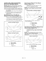
Place Discharge Chute in Operating
Position
and understand
WARNING:
AVOID
the INJURY.
entire Safety
Read
section before proceeding.
Tools
Required
,_
Adjustable wrench
mower
unlessDothe
WARNING:
notdischarge
operate chute
is in the operating position.
9/16" wrench
Prior to operating the unit, remove the
discharge chute from the transport position
and place the discharge chute in the
operating position (figure 4).
Petroleum jelly or dielectric grease.
Unpack
Unit
Remove unit and all other components from
the shipping container. Engage transmission
bypass lever (see MOVING UNIT
MANUALLYon page 14). Push unit from
container onto a level surface. Disengage
transmission bypass lever.
Connect
Discharge Chute in Transport
Position
Battery
See Battery Removal and Installation on
page 21 and perform steps 2 and 3 in the
installation section.
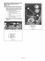
Place
(figure
Unit in Operating
3):
Position
NOTE: The unit is shipped with the seat
positioned as far back as possible.
1. Tip seat forward and adjust the seat as
needed (see ADJUSTING STEERING
LEVERS on page 22).
2. Remove eccentric spacers and rotate
steering levers to the operating position.
reinstall spacers. Do not tighten.
3. Adjust steering levers (see ADJUSTING
STEERING LEVERS on page 22).
Discharge
Chute in Operating Position
Figure 4
1.
2.
3.
4.
Seat
Steering
Lever
Eccentric
Spacer
Handlebar
Brackets
Figure 3
GB - 10
Check Engine Oil Level
1. Refer to Engine Manual.
Level Mower Deck
Check Tire Pressure
CAUTION:
Avoid injury! Explosive
separation of tire and rim parts is
possible when they are serviced
incorrectly:
Do not attempt to mount a tire
See on page 18.
Fill Fuel Tanks
without the proper equipment
and experience
to perform the
See FILLING FUEL TANKSon page 13.
Adjust Seat
See Adjusting Seat on page 13.
Check Safety Interlock
job.
Do not inflate the tires above
the recommended
pressure,
Do not weld or heat a wheel
System
and tire assembly.
cause an increase
WARNING: Safety interlock failure
and improper operation of unit can
result in death or serious injury.
Check system before each use to
make sure it is functioning
properly.
pressure resulting in an
explosion, Welding can
structurally
the wheel.
function
the tire assembly
of all controls
See OPERATION
weaken
or deform
Do not stand in front or over
See Safety Interlock System on page 12.
Check
Heat can
in air
when
inflating. Use a clip-on chuck
and extension
hose long
on page 12.
enough to allow you to stand
to one side.
See SPECIFICATIONS
on page 29.
[_o]_hj_[o]l[,,..'-]
P'_,_
_,I n_]
I_1_:_u|_"]
13
11
10
1.
2.
3.
4.
9
Ignition Switch
PTO Switch
Throttle Lever
Seat
5. Steering Levers
6. Parking Brake
7. Fuel Tank
Figure 5
8. Mower Lift Pedal
9. Mower Deck
10.
11.
12.
13.
GB- 11
Discharge Chute
Fuel Gauge
Choke Control
Hour meter
12
Throttle
A
Lever
Fast (1) - Increases
engine speed.
and
ARNING:
understand
AVOID
theINJURY.
entire
Safety
Read
section before proceeding.
CONTROLS AND FEATURES
See figure 5 for all controls and features
locations.
Safety Interlock
System
Slow (2) - Decreases
engine speed.
WARNING: Safety interlock failure
and improper operation of unit can
result in death or serious injury.
Check system before each use to
make sure it is functioning
properly.
Choke Control
Use to start a cold engine. Push
Perform the following tests to ensure the
safety interlock system is working properly. If
the unit does not perform as stated contact
our Ariens dealer for repairs.
Test
Steering
Lever
PTO
Parking
Brake
Engine
1
Neutral
Position
Off
Engaged
Starts
2
Neutral
Position
On
Engaged
Doesn't
Start
3
Neutral
Position
Off
Disengaged
Doesn't
Start
4*+
Out of
Neutral
Position
Off
Disengaged
Shuts
Off
Neutral
Position
On
5*+
I
I
NOTE: Do not choke a warm engine.
Parking
Engaged
Shuts
Off
operator position to start a cold
engine. Pull the choke lever
thechokeleveraway
from
toward the operator position
when the engine starts to run
smoothly.
Brake
Engages (2) and
disengages (1) parking
brake.
2
Power
Take-Off
(PTO)
+ Operator lifts off seat.
Ignition
1
Switch
Engages (2)
* Test with engine running.
O "=_<_:3
Switch
1
anddisengages(1)
mower
blades.
Operate ignition
switch with a
removable key.
Ignition switch has
four positions:
Stop (1), Headlight
(2), Run (3), Start (4).
See STARTING AND
SHUTTING OFF
Hour Meter
ENGINE on page 15
for detailed
instructions on how to
start engine.
GB - 12
Records total number of
hours engine has been run.
NOTE: Hour meter will
continue to run if ignition key
is left in the run position with
the engine turned off.
Press
mower
liftpedal
andinstall
adjustment
SteeringLevers
adjustment
hole.
Reverse
(1)-Pullboth
steering
levers pininthedesired
NOTE:
Adjusting
theseat
backward.
further
forward
willhelp
Forward
(2)- Push
bothsteering
levers
increase
theleverage
in
forward.
lifting
themower
deck(see
Adjusting Seat on
Left(3)- Pullleftsteering
lever
back
or
page 13).
push
rightsteering
lever
forward
ora
combination
ofboth.
Right
(4)- Pullright
steering
lever
back Adjusting Seat
Lift adjustment lever and slide seat forward or
orpush
leftsteering
lever
forward
ora
backward to the desired position.
combination
ofboth.
NOTE: To stop, return both steering levers to
neutral.
NOTE: The steering levers must be in the
neutral position to start the engine.
NOTE: The parking brake must be
disengaged prior to moving the steering
levers from the neutral position.
Mower Lift Pedal (Figure
Raises and lowers the deck.
1
3
1. Seat
2. Adjustment
Lever
Figure 7
FILLING FUEL TANKS
6)
1. Clean fuel caps and surrounding area to
prevent dust, dirt, and debris from
entering fuel tanks.
2. Remove fuel caps.
2
IMPORTANT: See Engine Manual for correct
type and grade of fuel.
3. Fill fuel tanks to 2-1/2 in. (6.35 cm)
below bottom of filler neck. See
SPECIFICATIONS on page 29 for
capacity of fuel tanks.
4. Replace fuel caps.
1. Adjustment Pin
2. Mower Lift Pedal
3. Adjustment
Hole
Figure 6
NOTE: The adjustment pin is used to set the
height of the mower deck. See
SPECIFICATIONS on page 29 for cutting
height dimensions.
GB - 13
GASOLINE
STOPPING IN AN EMERGENCY
IMPORTANT: ALWAYS use gasoline that
meets the following guidelines:
Bring steering levers back to neutral, set
parking brake, and turn off engine.
Clean, fresh gasoline.
A minimum of 87 octane/87 AKI (91
RON). High altitude use may require a
different octane. Consult your engine
manual.
Gasoline with up to 10% ethanol
(gasohol) or up to 15% MTBE (methyl
tertiary butyl ether) is acceptable.
Use of any gasoline other than those
approved above may void the engine
warranty. If the pumps are not marked
for the content of alcohol or ethers,
check ethanol and MTBE levels with
the fuel supplier.
Do not modify the fuel system to use
different fuels.
MOVING UNIT MANUALLY
or
bypass transmission
and coast
WARNING:
DO NOT disengage
downhill.
Disengage (2) transmission bypass levers to
drive unit and engage (1)transmission
bypass levers to push unit manually
(figure 8).
Never mix oil and gasoline.
NOTE: All gasoline is not the same. If the
engine experiences starting or performance
problems after using a new gasoline, switch
to a different fuel provider or fuel brand.
IMPORTANT: Excessively oxygenated or
reformulated fuels (fuels blended with
alcohols or ethers) can damage the fuel
system or cause performance problems. If
any undesirable operating problems occur,
use a gasoline with a lower percentage of
alcohol or ether.
Fuel Stabilizer
Gasoline left in the fuel system for extended
periods without a stabilizer will deteriorate,
resulting in gum deposits in the system.
These deposits can damage the carburetor
and the fuel hoses, filter and tank. Prevent
deposits from forming in the fuel system
during storage by adding a quality fuel
stabilizer to the fuel. Follow the
recommended mix ratio found on the fuel
stabilizer container.
1
1. Transmission
2. Transmission
Disengaged
2
Bypass Lever Engaged
Bypass Lever
Figure 8
GB - 14
STARTING AND SHUTTING OFF
ENGINE
Starting
TRANSPORTING
the Engine
NOTE: Disengage the PTO, engage the
parking brake, and place the steering levers
in neutral prior to starting the engine.
1. If the engine is cold, push the choke
control away from operator position to
start. If the engine is warm or hot, do not
use choke.
2. Move the throttle to 1/3 Fast position.
See Engine Manual for detailed
instructions.
FOR BEST PERFORMANCE
Cut grass when it is dry.
Keep mower blades sharp.
Keep mower deck properly leveled.
IMPORTANT: DO NOT operate starter for
more than 15 seconds per minute as damage
can occur.
3. Turn ignition key to start position and
release once the engine has started.
4. Pull the choke lever toward operator
position when the engine is warm. Wait
until the engine is running smoothly
before operation.
Adjust anti-scalp rollers to prevent scalping.
Do not set height of cut too low. For very tall
grass, mow twice.
Do not travel too fast.
Mow with the engine set at full throttle.
When mulching, only remove 1/3 of grass
length per cutting.
Discharge clippings into areas already cut.
Vary cutting pattern with each mowing.
IMPORTANT: Let the engine warm up
several seconds to several minutes
depending on outside temperature.
Stopping
UNIT
ALWAYS shut off engine, set parking brake,
remove key, and close fuel shut-off valve or
drain fuel when transporting unit on a truck or
trailer. Tie unit down securely. Do not tie
down by linkages, guards, cables or other
parts that may be damaged.
Do not allow grass or debris to collect inside
of mower deck. Clean after each use.
the Engine
1. Stop unit.
2. Disengage PTO.
3. Set throttle lever to slow.
4. Turn ignition switch to off position and
remove key.
5. Set parking brake.
OPERATING MOWER
1. Start engine.
2. Set throttle lever to fast.
IMPORTANT: Never engage PTO if mower is
plugged with grass or other material.
3. Engage PTO to start mower blades.
NOTE: The parking brake must be
disengaged prior to moving the steering
levers from the neutral lockout position.
4. Release parking brake.
5. Use steering levers to move the unit.
6. Disengage PTO to stop mower blades.
GB- 15
_1
and
ARNING:
understand
AVOID
theentire
INJURY.
Safety
Read
section before proceeding.
NOTE: To have full access to the engine, the
seat must be tipped forward (see TIPPING
SEAT FORWARD on page 17) and the hood
opened (see OPENING AND CLOSING
HOOD on page 18).
IMPORTANT: Proper maintenance can
prolong the life of unit. The following chart
shows the recommended service schedule.
Refer to the maintenance instructions in the
Engine Manual for additional information.
Interval
Task
.
Action
Check
Safety
Interlock
System
WARNING: Safety interlock system failure and improper
operation of unit can result in death or serious injury. Test
this system each time the unit is operated. If this system
does not function as described, do not operate until repairs
are made (see Safety Interlock System on page 12).
Check
Parking
Brake
Engage parking brake and engage transmission bypass lever (see
MOVING UNIT MANUALLY on page 14). Push unit. If unit rolls,
contact your Ariens Dealer.
Clean Unit
Clean engine, battery, seat, mower deck, etc. of all dirt and debris. Do
not use solvents, hard cleaners, or abrasives.
NOTE: Protect painted surfaces with automotive type wax.
See SPECIFICATIONS on page 29 for correct tire pressure.
IMPORTANT: Do not spray the unit with water, especially when the
unit is warm from operation. Water can seep into bearings and
damage them.
Each Use
Check
Tires
parts is possible
are serviced
incorrectly:
CAUTION:
Avoid when
injury!they
Explosive
separation
of tire and rim
•Do not attempt to mount a tire without the proper equipment
and experience to perform the job.
,_
Do not inflate the tires above the recommended
pressure.
Do not weld or heat a wheel and tire assembly. Heat can cause
an increase in air pressure resulting in an explosion. Welding can
structurally weaken or deform the wheel.
Do not stand in front or over the tire assembly when inflating. Use
a clip-on chuck and extension hose long enough to allow you to
stand to one side.
Check
Mower
Blades
CAUTION:
Check for worn or damaged mower blades.
GB - 16
Interval
Task
Action
Follow
Engine
Manual
Mainten-
Perform scheduled engine
maintenance. Refer to Engine
Manual for detailed instructions.
Each Use ance
Schedule
NOTE: To drain the oil, use the oil
drain hose (1)supplied with unit, not
the drain plug that is shown in the
Engine Manual.
SI_!S
I
Check
Battery
Lubricate
Unit
25 Hours
or Every
Season
50 Hours
or Every
Season
100
Hours or
Every
Season
Check
Fasteners
Check mower blade mounting hardware and all other fasteners.
Replace fasteners that are missing or damaged. Tighten all nuts and
bolts to the correct torque value.
Check All
Belts
Replace worn or deteriorated
Check PTO belt (see REPLACING
PTO belt location).
[,._o]_l
_
belts.
Check hydrostatic belt (see REPLACING
on page 24 for hydrostatic belt location).
HYDROSTATIC
PTO BELT on page 23 for
!'_,1
_,II] V_,!I]_lL,.!l II_vt
I=1_,/ Lr,.l
and
ARNING:
understand
AVOID
the INJURY.
entire Safety
Read
section before proceeding.
TIPPING SEAT FORWARD
Put steering levers up and tip seat forward.
1.
GB - 17
BELT
Seat Tipped Forward
Figure 9
OPENING AND CLOSING HOOD
REPLACING MOWER BLADE
To open, pull up on the back of the hood until
hood hits the hood stop and push down on
back of hood to close (figure 10).
Remove (Figure 12)
CAUTION: Mower blades are
sharp and can cut you. Wrap the
blades or wear gloves, and use
extra caution when servicing them.
Hood tipped open.
1. Block mower blades to prevent rotation.
2. Remove mounting hardware and mower
blades from mower deck.
Install (Figure
12)
1. Install mower blades on mower deck
with mounting hardware.
2. Torque 5/8-inch hex bolt to 80 to
120 Ibf-ft (108 to 163 N°m).
Figure 10
OPENING DECK ACCESS PLATE
1. Install adjustment pin in the first
adjustment hole (figure 11).
2. Put parking brake on.
3. Raise deck access plate.
1
f
1.
2.
3.
4.
1. Adjustment Pin
2. Deck Access plate
Figure 11
Flat Washer
Bevel Washer
5/8-inch Hex Bolt
Mower Blade
Figure 12
GB - 18
LEVELLING AND ADJUSTING
PITCH OF MOWER DECK
The Forward
Blades
NOTE: Adjust on a level surface, with the
tires inflated to the correct air pressure (see
SPECIFICATIONS on page 29).
There are three measurements required to
level and adjust the pitch of the mower deck.
1. The distance from the mower blades to
the ground.
2. The forward pitch of the mower blades.
3. The pitch of the mower blades from
side-to-side.
The Distance
Blades
From
Pitch Of The Mower
(Figure 14):
Should be 0.0 in. (0.0 mm) to 1/4 in.
(6.35 mm) pitched forward.
NOTE: This measurement must be taken
when the mower blades ends are facing
forward.
Forward Pitch of Mower Blades
3
1
2
The Mower
To The Ground
(Figure
13):
In the lowest cutting position should be
1-1/2 in. + 1/4 in. (3.8 cm + 0.64 cm).
In the highest cutting position should be
4-1/2 in. + 1/4 in. (11.4 cm + 0.64 cm).
Lowest Cutting Position
3
1
2
Forward Pitch = 0.0 in. (0.0 mm) to
1/4 in. (6.35 mm)
1. Mower Deck
2. Mower Blade
3. Ground
Figure 14
The Pitch Of The Mower
Position
1
3
2
From
Should be within 1/4 in. (6.35 mm) as
measured on each side of the mower
deck.
1-1/2 in. + 1/4 in. (3.8 cm + 0.64 cm)
Highest Cutting
Blades
(Figure 15):
Side-To-Side
NOTE: This measurement must be taken
when the mower blade ends are
perpendicular (at a right angle) to the frame
of the unit.
Side-To-Side
Pitch
4-1/2 in. + 1/4 in. (11.4 cm + 0.64 cm)
1. Mower Deck
2. Mower Blade
3. Ground
1/4-in. (6.35 cm)from
1.
2.
3.
Figure 13
Side-To-Side
Mower Deck
Mower Blade
Ground
Figure 15
GB - 19
Adjusting The
Mower
(Figure
Blade
17):
Mower Deck To
Height And Pitch
Adjust
NOTE: Adjusting the mower deck will adjust
the height and pitch of the mower blades.
1. Adjust the trunnions first and re-take the
three measurements required to level
and adjust the pitch of the mower deck.
These measurements are:
a. The distance from the mower
blades to the ground.
b. The forward pitch of the mower
blades.
c.
The pitch of the mower blades
from side-to-side.
2. Repeat step 1 as needed until all three
measurements are within the tolerances
specified.
1.
2.
3.
Deck Link
Mower Deck
Trunnion
Figure 17
3
1.
2.
3.
4.
5.
6.
5
Rear Trunnion
PTO Belt
Mower Deck
Drag Link
Front Trunnion
Lift Arm
Figure 16
GB - 20
SERVICING BATTERY
Install
Battery
Removal
Cleaning
(Figure
and Installation
(Figure 18)
Remove
19)
2. Connect positive (+) cable first, then
negative (-) cable.
3. Apply petroleum jelly or dielectric grease
to battery cable ends and terminals.
4. Tip seat back (see TIPPING SEAT
FORWARD on page 17).
terminals
relatedposts,
accessories
ARNING:andBattery
contain lead and lead compounds,
chemicals known to the State of
California to cause cancer and
reproductive harm. Wash hands
after handling.
_
(Figure
1. Install battery on the unit with battery
hold-down bracket.
NOTE: Unit comes equipped with a
maintenance-free battery that requires no
regular maintenance except cleaning the
terminals and periodic charging.
1. Tip seat forward (see TIPPING SEAT
FORWARD on page 17).
2. Disconnect negative (-) cable first, then
positive (+) cable.
3. Loosen and remove bolts.
4. Remove battery hold-down bracket and
battery from unit.
Battery
and Battery
1. Tip seat forward (see TIPPING SEAT
FORWARD on page 17).
2. Disconnect negative (-) cable first, then
positive (+) cable.
3. Clean battery cable ends, negative (-)
terminal, and positive (+) terminal with a
wire brush and rinse with a weak baking
soda solution.
4. Connect positive (+) cable first, then
negative (-) cable.
5. Apply petroleum jelly or dielectric grease
to battery cable ends and terminals.
6. Tip seat back (see TIPPING SEAT
FORWARD on page 17).
6
2
4
1
Battery Hold-Down Bracket
Bolts
Figure 18
2
3
1.
2.
3.
4.
5.
6.
1
Battery Hold-Down Bracket
Negative (-) Cable
Negative (-) Terminal
Battery
Positive (+) Cabel
Positive (+) Terminal
Figure 19
GB - 21
Cables
19)
Charging the Battery
ADJUSTING
(Figure 19)
Adjusting
(Figure
WARNING: FROZEN BATTERIES
CAN EXPLODE and result in
death or serious injury. DO NOT
charge a frozen battery. Let the
battery thaw before charging.
STEERING LEVERS
Steering
Lever
Height
20)
NOTE: Perform steps 1 and 2 for both
steering levers.
1. Remove mounting hardware and move
handlebar up or down until the steering
levers are at the appropriate height.
2. Install mounting hardware.
NOTE: Align handlebars by adjusting
eccentric spacer until the handlebar height is
the same.
Follow First Aid directions for contact with
battery fluid.
External Contact: Flush with water.
Eyes: Flush with water for at least 15
minutes and get medical attention
immediately!
Internal Contact: Drink large quantities
of water. Follow with Milk of Magnesia,
beaten egg or vegetable oil. Get medical
attention immediately!
In case of internal contact, DO NOT
induce vomiting!
IMPORTANT: DO NOT fast charge. Charging
at a higher rate will damage or destroy
battery.
IMPORTANT: ALWAYS follow information
provided on battery and battery charger.
Contact battery and battery charger
manufacturers for detailed instructions.
1. Remove battery from unit (see Battery
Removal and Installation on page 21 ).
2. Place battery in a well-ventilated area.
3. Connect positive (+) lead of charger to
positive (+) terminal, and negative (-)
lead of charger to negative (-) terminal.
4. Charge battery according to battery
charger and battery manufacturers'
instructions.
5. Install battery on unit (see Battery
Removal and Installation on page 21 ).
Jump-Starting
Ariens does not recommend jump-starting
your unit. Jump-starting can damage engine
and electrical system components. See your
engine manual for more detailed information.
1. Handlebar
2. Steering Lever
3. Mounting Hardware
4. Adjustment Holes
5. Eccentric Spacer
6. Shipping Adjustment
Figure 20
GB - 22
Holes
Forward and Reverse
Adjustment
(Figure
REPLACING PTO BELT
Speed
Remove
21)
(Figure
22)
1. Lower mower deck to the ground.
IMPORTANT: The unit should track within
2 feet (0.61 m) of a straight line for 30 feet
(9.14 m).
2. Remove belt covers from mower deck.
The travel of the steering levers may need
adjustment if:
_i
The unit turns to the right or left when
both steering levers are pushed as far
forward as possible.
releasing idler
CAUTION:
Usespring
care when
tension.
Keep body parts well away from
idler when performing this
operation.
3. Hook a puller into idler hole and pull idler
arm towards outside of unit until tension
is removed from PTO belt.
The unit turns to the right or left when
both steering levers are pulled back as
far rearward as possible.
NOTE: The side the unit turns toward
indicates that the wheel on that side is turning
slower than the other wheel. Either the wheel
that is turning faster needs to slow down or
the wheel that is turning slower needs to be
sped up to allow the unit to travel in a straight
line.
3
4
2
1
1. Determine which way the unit turns.
NOTE: The forward travel adjustment bolt
adjusts the rear travel of the steering lever.
The rear travel adjustment bolt adjusts the
forward travel of the steering lever.
2. Adjust speed by loosing jam nut and:
Turning adjustment bolt clockwise to
decrease steering lever travel.
1.
2.
3.
4.
5.
6.
7.
Turning adjustment bolt counter
clockwise to increase steering lever
travel.
Idler Spring
Electric Clutch
PTO Belt
Idler Hole
Idler Pulley
Idler Arm
Belt Cover
Figure 22
4. Remove PTO belt from left mower deck
pulley.
5. Slowly release idler arm until tension is
removed from idler spring.
6. Remove PTO belt from mower deck and
electric clutch.
Install (Figure 22)
NOTE: Do not install PTO belt on left mower
deck pulley in step 1.
1. Install PTO belt on electric clutch and
mower deck.
1.
2.
3.
2. Hook a puller into idler hole and pull idler
arm towards outside of unit until PTO
belt can be routed around left mower
deck pulley.
3. Slowly release idler arm until idler pulley
rests firmly against PTO belt.
4. Install belt covers on mower deck.
Forward Travel Adjustment Bolt
Rear Travel Adjustment Bolt
Steering Lever
Figure 21
GB - 23
REPLACING HYDROSTATIC
Remove
(Figure
BELT
To Add Hydraulic
(Figure
23)
1. Remove the cap from the expansion
tank.
1. Remove PTO belt (see REPLACING
PTO BELT on page 23).
2. Disconnect electric clutch connector.
2. Fill the expansion tank with 20W-50
engine oil with an SL API classification
until oil level reaches the cold fill line on
the tank.
3. Remove clutch stop.
_
3. Install the expansion tank cap and then
purge the system. See "Purging the
Hydraulic System" on page 25.
releasing
AUTION:idler
Usespring
care when
tension.
Keep body parts well away from
idler when performing this
operation.
4. Disconnect idler spring.
5. Remove hydrostatic belt from
hydrostatic transmission pulleys, pulley,
electric clutch, and idler.
Install
(Figure
Fluid:
24)
The hydraulic fluid should be at the cold
fill line of the expansion tank.
23)
1. Install hydrostatic belt on idler, electric
clutch, pulley, and hydrostatic
transmission pulleys.
2. Connect idler spring.
3. Install clutch stop.
4. Connect electric clutch connector.
5. Install PTO belt (see REPLACING
BELTon page 23).
PTO
2
6
Figure 24
4
5
Change Hydraulic Fluid and Filter
(Figure
1.
2.
3.
4.
5.
6.
Hydrostatic Belt
Hydrostatic Transmission
Pulley
Electric Clutch
Idler
Idler Spring
Pulley
2. Remove the filter guard and oil filter from
the transaxle.
Figure 23
Check
(Figure
Hydraulic
Fluid
25)
NOTE: Change hydraulic fluid and filter after
the first 75 hours of operation and then every
400 hours. Use 20W-50 engine oil with an SL
API classification.
1. Place container under oil filter to catch
oil.
3. Remove the oil drain plug or fitting from
the inlet port and allow the transaxle to
drain completely.
4. Clean the filter mounting surface and
then lubricate rubber gasket on new oil
filter with clean hydraulic oil.
5. Spin new oil filter onto filter housing until
it makes contact. Tighten oil filter
another 3/4 turn.
Level
24)
Check the system with the unit cold and
parked on a flat, level surface.
Then run the unit for about one minute and
recheck the levels.
GB - 24
6.Install
thefilterguards
removed
in
step2.Tighten
themounting
screws
to
65Ibf-in
(7.3N°m).
7.Fillwith20W-50
engine
oilwithanSL
APIclassification
untiloilappears
atthe
bottom
ofthedrain
plug(about
2quarts
pertransaxle).
Install
thedrain
plugand
tighten
itto180Ibf-in
(20.3
N°m).
8.Repeat
steps
1-7fortheother
transaxle.
9.Follow
theinstructions
in"ToAdd
Hydraulic
Fluid:"
onpage
24.
Purging the Hydraulic System
,_
requires operating
WARNING:
This adjustment
the engine.
Use extreme care to avoid
contact with moving parts and hot
surfaces. Be sure rear of unit is
well supported and secure before
starting engine.
1. With the unit up to and facing a wall, jack
up the unit so that both drive wheels are
off the ground.
2. Disengage the parking brake and put the
transaxle bypass levers in the neutral
position (see MOVING UNIT
MANUALLY on page 14).
3. Start the engine and slowly move the
steering levers in forward and reverse
five or six times.
4. Stop the engine and put the transaxle
bypass levers in the drive position (see
MOVING UNIT MANUALLY on
page 14).
5. Start the engine and slowly move the
steering levers in forward and reverse
five or six times.
6. Stop the engine, check the oil level and
add oil as needed.
1.Drain
Plug
2.OilFilter
3.Filter
Guard
4.Mounting
Hardware
Figure
25
7. Repeat steps 2-6 until the transaxles
operate smoothly in forward and reverse
at normal speeds without excessive
noise.
[,,.']i_o_
Short
Term Storage
=1
Fuel System
IMPORTANT: NEVER clean unit with highpressure water or store unit outdoors.
Remove all dirt, grease, leaves, etc. Store in
a clean dry area.
Inspect unit for signs of wear or damage.
Ensure all fasteners are properly tightened.
Long Term Storage
Follow all instructions under Short Term
Storage.
Gasoline left in the fuel system for extended
periods without a stabilizer will deteriorate,
resulting in gum deposits in the system.
These deposits can damage the carburetor
and the fuel hoses, filter and tank. Prevent
deposits from forming in the fuel system
during storage by adding a quality fuel
stabilizer to the fuel. Follow the
recommended mix ratio found on the fuel
stabilizer container.
To treat the fuel system for storage:
Remove and fully charge battery. Store in a
clean dry area.
Drain fuel from fuel tank.
1. Add fuel stabilizer according to
manufacturers's instructions.
Refer to Engine Manual for the proper engine
storage procedures.
Touch up all scratched or chipped paint
surfaces.
2. Run engine for at least 10 minutes after
adding stabilizer to allow it to reach the
carbu retor.
NEVER store the engine with fuel in the fuel
tank inside of a building with potential
sources of ignition.
GB - 25
Engine will not
crank/start.
Engine
runs
rough.
Unit does not
move with
engine running
when using
steering levers.
1,
Safety interlock
system is not
engaged or is
faulty.
1,
Check safety interlock system (see
Safety Interlock System on
page 12).
2.
Fuel tanks empty.
2,
Fill fuel tanks (see FILLING FUEL
TANKS on page 13).
3.
Discharged
battery.
3.
Charge battery (see Charging the
Battery on page 22).
4.
Poor connection
between battery
and battery cables.
4.
Tighten battery cables and/or clean
battery and battery cables (see
Cleaning Battery and Battery Cables
on page 21).
5,
Spark plug wire(s)
loose or spark
plug(s) faulty.
5,
Connect spark plug wire(s) or
replace spark plug(s). Refer to
Engine Manual for detailed
instructions.
6.
Faulty electrical
system.
6.
Contact yourAriens
7.
Faulty engine.
7.
Contact your Ariens Dealer.
1.
Choke engaged.
1.
Disengage choke.
2.
Air filter cartridge
plugged.
2.
Clean or replace air filter cartridge.
Refer to Engine Manual for detailed
instructions.
3.
Faulty engine.
3.
Contact yourAriens
1.
The transmission
bypass lever is
engaged.
1.
Disengage transmission bypass
lever (see on page 16).
2.
Faulty hydrostatic
belt.
2,
Replace hydrostatic belt (see
REPLACING HYDROSTATIC BELT
on page 24).
3.
Faulty
transmission.
3.
Contact yourAriens
GB - 26
Dealer.
Dealer.
Dealer.
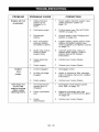
PTO or mower
blades do not
engage or shuts
off.
1.
Operator presence
switch not
depressed.
1.
Depress operator presence switch
by sitting on seat.
2.
Faulty operator
presence switch.
2.
Contact yourAriens
3.
Electric clutch
connector is loose
or disconnected.
4.
Faulty PTO belt.
4.
Replace PTO belt (see REPLACING
PTO BELT on page 23).
5.
Faulty PTO switch,
wires, connectors,
or clutch.
5.
Contact your Ariens Dealer.
1.
Engine oil level
low.
1.
Add engine oil. Refer to Engine
Manual for detailed instructions.
2.
Cooling system
plugged.
2.
Clean cooling system. Refer to
Engine Manual for detailed
instructions.
3.
Faulty engine.
3.
Contact yourAriens
Dealer.
1.
The parking brake
needs adjustment.
1.
Contact yourAriens
Dealer.
2.
Faulty parking
brake.
2.
Contact yourAriens
Dealer.
Hour meter
continues when
engine not
running.
1.
Ignition key is in
the run position
with engine turned
off.
1.
Turn ignition key to the off position.
Unit does not
travel in a
straight line.
1.
Incorrect tire
pressure.
1.
Check tire pressure (see
SPECIFICATIONS on page 29)
2.
Steering levers
need adjustment.
2.
Adjust steering levers (see Forward
and Reverse Speed Adjustment on
page 23)
3.
Hydrostatic
transmission
and/or linkage
needs adjustment.
3.
Contact yourAriens
Dealer.
1.
Hydrostatic
transmission
and/or linkage
needs adjustment.
1.
Contact yourAriens
Dealer.
Engine
overheats.
Unit moves with
engine off and
parking brake
engaged.
Unit creeps with
steering levers
in neutral
position.
GB - 27
3.
Dealer.
Connect the electric clutch
connector. See REPLACING
HYDROSTATIC BELT on page 24
for the electric clutch connector
location.
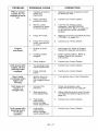
Poor cutting
quality.
1.
Mower deck not
level or mower
pitch is incorrect.
2.
Dull or faulty
mower blades.
Be sure to always use genuine Ariens parts
to keep your unit running like new.
Part No.
Qty
21547800
1
Description
1
Fuel Filter
21548000
1
Air Filter
21548100
1
Engine Oil Filter
21545100
1
Hydraulic Oil Filter
02961600
1
42-Inch Mower Blade
03288600
1
42-Inch Mulching Blade
02982000
1
48-Inch Mower Blade
00273000
1
48-Inch Mulching Blade
02961700
1
54-Inch Mower Blade
03288700
1
54-Inch Mulching Blade
07242200
1
Hydrostatic Belt
07200037
1
42-Inch PTO Belt
07200436
1
48-Inch PTO Belt
07200023
1
54-Inch PTO Belt
Level and adjust pitch of mower
deck (see The Distance From The
Mower Blades To The Ground
(Figure 13): on page 19).
2.
Sharpen mower blades or replace
mower blades (see REPLACING
MOWER BLADE on page 18).
See your authorized Ariens dealer to
add these optional accessories to your
unit.
Part No.
Spark Plug
21547900
1.
Description
71502900
Dump Cart
71509000
42-Inch Mulch Kit
71508700
48-Inch Mulch Kit
71509100
54-Inch Mulch Kit
71503200
48-Inch Aerator
71503300
36-Inch Roller
71503400
48-Inch Dethatcher
71510300
15-Gallon Sprayer
71503600
Spreader
71509200
Sunshade
71503800
48-Inch Lawn Sweeper
81502200
3-Bag Powered Bagger
71509300
Trailer Hitch
71509400
Light Kit
GB - 28
Model Number
Model
915145
915147
Zoom XL 42
Zoom XL 48
915149
Zoom
XL 54
Kawasaki FR651
Engine
Displacement
45.5 (746)
- in.3 (cc)
Max Governed RPM
(May be different from
maximum RPM)
3600 + 0
360050
Speed
Forward Max. - m.p.h (km/h)
6.5 (10.46)
Reverse Max. - m.p.h (km/h)
3 (3.2)
Turning
Zero
Radius
Brakes
Internal Transmission
Electrical
Starter
Electric
12 Volt Maintenance
Battery
Free
Electric Clutch/Brake
PTO (Power Take Off)
Fuel
Fuel Type
Refer to Engine Manual
Fuel Tank Capacity - gal. (L)
4.5 (17.0)
Transmission
Hydrostatic Drive
Size and Weight
Length - in. (cm)
68 (173)
Width - in. (cm)
44 (111.8)
49 (124.5)
56 (142.2)
Weight - Ibs (Kg)
656 (297.6)
667 (302.5)
680 (308.4)
Height - in. (cm)
41 (109)
Tires
Front Tire Size - in.
11 x4
Rear Tire Size - in.
20 x 8
20 x 10
Front Tire Pressure psi (kPa)
46 (317)
Rear Tire Pressure psi (kPa)
10 (69)
Mower Deck
Cutting Height - in. (cm)
1-1/2 -4-1/2
Cutting Width - in. (cm)
Max. Towing
Ibs (kg)
Capacity
Max. Tongue
Ibs (kg)
Weight -
42 (107)
-
(3.81 - 11.4)
48 (122)
300 (136)
30 (13.6)
GB - 29
54 (137)
Two-Year Limited Lawn and
Garden Consumer Ride-On
Warranty
Ariens Company (Ariens) warrants to the original purchaser that Ariens and Gravely brand consumer
products manufactured and sold by Ariens will be free from defects in material and workmanship for a period
of two years after the date of purchase. An authorized Ariens dealer (Ariens brand products) or Gravely
dealer (Gravely brand products) will repair any defect in material or workmanship, and repair or replace any
defective part, subject to the conditions, limitations and exclusions set forth herein. Such repair or
replacement will be free of charge (labor and parts) to the original purchaser except as noted below.
Five-Year
Limited
Warranty
on Mower
Deck Shell
The deck shell on zero-turn riding mowers is warranted to the original purchaser for five years from
the date of purchase. Any defect in material or workmanship of the deck shell will be repaired free of
charge (parts and labor) to the original purchaser for two years after the date of purchase. For the third
through fifth year from the date of purchase, the parts required to repair a defect in material or workmanship of the deck shell, not the labor, will be provided free of charge.
Five-Year
Limited
Warranty
on Main Frame
The main frame on zero-turn riding mowers is warranted to the original purchaser
for five years from
the date of purchase. Any defect in material or workmanship of the main frame will be repaired free of
charge (parts and labor) to the original purchaser for two years after the date of purchase. For the third
through fifth year from the date of purchase, the parts required to repair a defect in material or workmanship of the main frame, not the labor, will be provided free of charge.
Two-Year
Limited
Warranty
on AMP TM Series Battery
Packs and Subassembfies
The battery pack and/or battery subassemblies on AMP series electric riding mowers is/are warranted
to the original purchaser for two years from the date of purchase. Ariens will replace, free of charge to
the original purchaser, any battery pack and/or battery subassembly that fails due to defect in material
or workmanship for one year after the date of purchase. For the next 12 months, Ariens will cover the
prorated cost of replacing a battery pack and/or battery subassembly that fails due to defect in material
or workmanship. This warranty does not apply to battery packs or battery subassemblies that fail due to
accident, neglect, abuse, improper maintenance, improper storage or improper charging procedures.
90-Day Limited
Warranty
on Service
Parts and Accessories
Genuine Ariens or Gravely brand service parts and accessories are warranted to be free from defects
in material and workmanship for a period of 90 days after the date of purchase. An authorized Ariens or
Gravely dealer will repair or replace any such part or accessory free of charge, except for labor, during
that period.
The duration of all warranties herein applies only if the product is put to personal use around a household or
residence. If the product is put to any business use, agricultural, commercial, or industrial, then the duration
of these warranties shall be 90 days after the date of purchase.
If any product is rented or leased, then the duration of these warranties
purchase.
shall be 90 days after the date of
Exceptions, Limitations, Exclusions
Customer
Responsibilities
Register the product immediately at the time of sale. If the dealer does not register the product, the
customer must complete the product registration card in the literature package and return it to the Ariens
Company, or register the unit online at www.ariens.com or www.gravely.com.
To obtain warranty service, the original purchaser must:
Perform the maintenance and minor adjustments explained in the owner's manual.
Promptly notify Ariens or an authorized
warranty service.
Ariens or Gravely service representative
of the need for
Transport the product to and from the place of warranty service.
Have the warranty service performed
by an authorized
Ariens or Gravely service representative.
ARIENS COMPANY
GRAVELY_>
I STENS_>I LOCKETS'
I NATIONALS>
MOWER I BYNORM_>
I EVERRIDEC_'
I GREATDANEc_'
Con Ride 2010
30
Tofind
anAriens
orGravely
authorized
service
representative,
contact
Ariens
at:
655
WR
. yan
Street
Brillion,
WI54110
(920)
7562141
www.ariens.com
www.gravely.com
Exceptions
and Limitations
Batteries are warranted only for a period of 12 months after date of purchase, on a prorated basis. For
the first 90 days of the warranty period, a defective battery will be replaced free of charge. If the
applicable warranty period is more than 90 days, Ariens will cover the prorated cost of any defective
battery, for up to 12 months after the date of purchase. This battery limited warranty does not apply to
the battery packs on AMP series products.
Exclusions - Items Not Covered by This Warranty
Engines and engine accessories
covered by this warranty.
are covered only by the engine manufacturer's
warranty and are not
Parts that are not genuine Ariens or Gravely service parts are not covered by this warranty.
The following maintenance, service and replacement items are not covered by this warranty unless
they are noted in the Limitations section above: lubricants, spark plugs, oil, oil filters, air filters, fuel
filters, brake linings, brake arms, brake shoes, runners, scraper blades, shear bolts, mower blades,
mower vanes, headlights, light bulbs, knives, cutters.
Any misuse, alteration, improper assembly, improper adjustment,
repair is not covered by this warranty.
neglect, or accident which requires
This warranty applies only to products purchased in the United States (including Puerto Rico) and
Canada. In all other countries, contact place of purchase for warranty information.
Disclaimer
Ariens may from time to time change the design of its products. Nothing contained in this warranty shall be
construed as obligating Ariens to incorporate such design changes into previously manufactured products,
nor shall such changes be construed as an admission that previous designs were defective.
LIMITATION
OF REMEDY
AND DAMAGES
Ariens Company's liability under this warranty, and under any implied warranty that may exist, is limited to
repair of any defect in workmanship, and repair or replacement of any defective part. Ariens shall not be
liable for incidental, special, or consequential damages (including lost profits). Some states do not allow the
exclusion of incidental or consequential damages, so the above limitation or exclusion may not apply to you.
DISCLAIMER
OF FURTHER
WARRANTY
Ariens Company makes no warranty, express or implied, other than what is expressly made in this
warranty. If the law of your state provides that an implied warranty of merchantability,
or an implied
warranty of fitness for particular
purpose, or any other implied warranty, applies to Ariens Company,
then any such implied warranty is limited to the duration of this warranty. Some states do not allow
limitations
on how long an implied warranty lasts, so the above limitation may not apply to you.
This warranty gives you specific legal rights, and you may also have other rights which
vary from state to state.
ARIENS COMPANY
GRAVELY®I STENSC_'
I LOCKETS'
I NATIONAL®I BYNORM<_'
I EVERRIDEC_'
I GREAT DANEc_'
Con Ride 2010
31
Ariens Company
655 West Ryan Street
Brillion, WI 54110-1072
920-756-2141
Fax 920-756-2407
www.ariens.com
A WARNING
A
The engine exhaust from this product
contains chemicals known to the State
of California to cause cancer, birth
defects or other reproductive
harm.