1
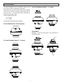
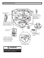
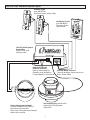
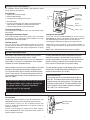
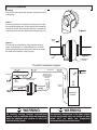
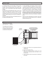
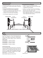
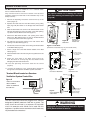
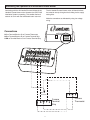
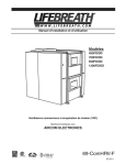
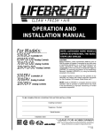
QUANTUM VENTILATION SYSTEM (QVS)
Quantum Ventilation System
93-QVSKIT contains:
Airia
1 COMBI Fan
1 Mounting Bracket (not shown)
1 Quantum Ventilation Box
1 Ventilation Control (part # 99BC-01)
2 Digital Electronic Timers
%
80
(part # 99-DET01)
HIGH
20
General
Table of Contents
The Quantum Ventilation System (QVS) replaces
multiple exhaust fans with one quiet, efficient, single
source fan.
General
Warranty ...........................................................................1
In-line Fan Set-up ..............................................................2
In-line Fan Assembly .........................................................3
Quantum Ventilation System Layout .................................4
The QVS PLUS Ventilation System Layout.......................5
Ventilation Control Part # 99-BC-01
How the Dehumidistat Works
20/40/60 Minute Timer (Part # 69-DET01) ........................6
In-line Fan Installation .......................................................7
Ducting the System
Weatherhood Installation...............................................8-9
Grilles................................................................................9
Installation of the Main Control
Electrical .........................................................................10
Interlocking Fan Operation to an
Airhandler/Furnace Blower .............................................11
Wiring Diagram ...............................................................12
In addition to quiet exhaust, the QVS can be upgraded at
any time with a balanced Heat Recovery Ventilator (HRV)
or Energy Recovery Ventilator (ERV). Refer to the
Lifebreath residential Operation & Installation manual for
HRV/ERV installation instructions. Manuals are available
for download at www.lifebreath.com.
Warranty
The Quantum Ventilation System (QVS) carries a 5 year
replacement parts warranty.
69-QVS-COMBI-456
0912
In-line Fan Set-up
Before installation, careful consideration must be given to
how this system will operate if connected to any other
piece of mechanical equipment. It is always important to
assess how the operation of any air movement device
may interact with vented combustion equipment (i.e. Gas
Furnaces, Oil Furnaces, Wood Stoves, etc.).
Airia Quantum Series in-line fans are approved for both
Residential and Commercial applications. The superior
plastic resin is suitable for applications requiring fire rated
materials and provides a quiet, weatherproof, versatile fan.
Plastic fans are suitable for indoor OR outdoor
installations and are suitable for temperatures of -40°F
(-40°C) to 140°F (60°C).
NEVER install a ventilator in a situation where its normal
operation, lack of operation or partial failure may result in
the backdrafting or improper functioning of vented
combustion equipment without proper safety/warning
devices installed as required.
Low voltage controls installed with the QVS are
compatible with future HRV/ERV upgrades.
CAUTION
WARNING
For general ventilation only. DO NOT use this fan to
exhaust hazardous or explosive material and
vapors.
Do not use fan where water can/will accumulate
inside fan housing. When required – always use
suitable electrical connections to prevent water
from entering the fan housing.
NBQ-COMBI-456 - Field Selectable 4", 5" or 6"
2.2 (275)
The duct system should be
sized for high speed
operation. Low speed
reduces air flow by
approximately 45%.
Static Pressure - in W.C. (Pa)
2.0 (250)
1.8(225)
1.6 (200)
1.4 (175)
1.2 (150)
1.0 (125)
0.8 (100)
0.6 (75)
6" Duct
0.4 (50)
0.2 (25)
4" Duct
0 (0)
0
(0)
5" Duct
100
125
150
175 200
225
250
275
300
325
75
50
25
(11.8) (23.6) (35.4) (47.2) (59.0) (70.8) (82.6) (94.4) (106.2) (118.0) (129.8) (141.6) (153.4)
Airflow - cfm (L/s)
Model 99-NBQCOMBI-456
Field Selectable 4”, 5”, or 6”
6" nominal duct collar
5" nominal duct collar
4" nominal duct collar
11-1/4" dia
3-1/4"
9-1/8"
2-5/8"
2
In-line Fan Assembly
Four Inch Dedicated (attach 2 – 4” collars)
The unique COMBI fan can be configured in either 4 inch,
5 inch, 6 inch, OR any combination of the three.
The collars will fit on the main housing with a tapered
friction fit. No sealant is required. Locate screw slot on
collar and use 1 - 1/4” hex head screw (supplied) per
collar to secure collar in place.
Collars included with this fan
• 2 – 4” collars
• 2 – 5” collars
The following configurations are available:
Six Inch Dedicated (no collars required)
Combination
Example -- 4 inch and 5 inch collars. Any combination of
sizes can be used.
4”
4”
Five Inch Dedicated (attach 2 - 5” collars)
5”
3
5”
Quantum Ventilation System Layout
20/40/60 Minute Timer
(part # 99-DET01)
Adjustable Techgrilles
(not included) exhaust the
stale air. Install
Techgrilles at each QVS
exhaust location
(bathroom, laundry).
Timers initiate high speed
fan operation for 20, 40 or 60
minutes. Up to 4 timers can be
installed on this system. Two
timers are included with this kit.
Airia
Ventilation Control
part # 99-BC-01
%
80
HIGH
The QVS System Control
Box and COMBI Fan
provide quiet, whole house
ventilation.
20
The Ventilation Control is a main
control used to initiate ON/OFF
and HI/LO speed fan operation.
Install only one of these controls
on the system. The Ventilation
Control is included with this kit.
Future HRV/ERV upgrade
WARNING
The make-up air intake must be insulated to the
trunk. An inline duct heater will be required if the
mixed air temperature is below 60°F.
4
The QVS PLUS Ventilation System Layout
20/40/60 Timers
(part #99-DET01)
Connect to Green, Yellow & Red
Ventilation Control
(part #99-BC01)
Connect to Green,
Yellow & Red
%
80
HIGH
20
The QVS PLUS System
Control Box
Attach to wall, stud,
ceiling joist etc.
QVS PLUS Furnace
Interlock Terminals
Refer to “Interlocking Fan
Operation to an Airhandler/
Furnace Blower” in this manual.
Terminal Block
Timers & Ventilation Control connect to
Green, Yellow & Red
Airia
Power Damper (not included)
Connect to DAMPER & 24 VOLTS
terminals on Terminal Strip.
Refer to the “Wiring the Power Damper”
section of this manual.
The Quantum Fan must be within
6 feet of QVS PLUS System
Control Box
5
Ventilation Control Part #99-BC-01
The Ventilation Control offers ON/OFF, High Speed/Low speed
plus an electronic dehumidistat.
Instruction card
Key Features
• 2 Speed Fan setting (Low/High)
• Electronic Dehumidistat
On indicator
light
• Instruction Card is inserted in the control
Dehumidistat
Indicator LEDs
%
80
High Speed
Indicator LED
• Slim-line design
HIGH
• Connect 3 wire 20 gauge low voltage wire between Green,
Yellow & Red on Ventilation Control and terminal block
located on Quantum Plus System Control Box.
20
High/Low
Speed button
Turning on the Control
ON/OFF button
Press and release the ON/OFF button. The "ON Indicator Light"
will illuminate.
Setting the Dehumidistat
Adjusting the Ventilation Speed
The unit will normally operate at low speed. Press and release
the SPEED button to initiate high speed ventilation. The "High
Speed Indicator LED" will illuminate.
Press and release the DEHUMIDISTAT button until the
DEHUMIDISTAT LED is at the desired setting. After 5 seconds
the dehumidistat light will either flash or be on continuous.
Humidity Control
A flashing light indicates the humidity level is higher than the
setting and the unit is operating on high speed ventilation. A
continuous light indicates the humidity level is lower than the
setting.
Your unit will produce a dehumidifying effect when outdoor
humidity levels are lower than indoor humidity levels. Never use
the dehumidistat feature when outdoor temperatures are above
59 F (15 C).
Note - Only 1 dehumidistat should be active on a system.
How the Dehumidistat Works
Often today’s well insulated, tight homes have high indoor
humidity levels during the heating season. Visible
condensation on the windows of your home is an indication of
high humidity. The amount of condensation on the windows
increases as outdoor temperatures drop.
A further dehumidification effect is achievable through the
dehumidistat setpoint of the Main Wall Control. Once the
humidity level exceeds this set point, the High speed exhaust
initiates. Following a reduction of the humidity level in the
home, the control reverts back to its previous setting.
When installed on the system, the optional Make-up Air Intake
achieves a dehumidifying effect during the heating season.
(For more information, refer to “Quantum Ventilation System
Layout” in this manual). This dehumidifying effect occurs during the heating season when outdoor temperatures are less
than 15°C (59°F).
The dehumidistat operates in a percentage range of relative
humidity (RH) with 80 being high and 20 being low. To
disable the dehumidistat, set it to 80%.
Dehumidistat Notes:
The average person is comfortable between 30% to
50% RH. The dehumidistat should be set to 80 for all
seasons except the heating season. The setting 80
disables the dehumidistat. The dehumidistat function
will be disabled if the outdoor temperature exceeds
15°C (59°F) for a 24 hour period.
The dehumidistat function should only be used if
the Optional Make-up Air intake is installed on
the system (refer to “Quantum Ventilation
System Layout” in this manual).
20/40/60 Minute Timer (Part # 69-DET01)
20/40/60 Minute Timer
Part # 99-DET01
Initiates high speed ventilation for 20, 40 or 60 minutes. The
20/40/60 Minute Status Lights indicate high speed operation.
20/40/60 Minute
Status Lights
Lockout Mode is useful if you wish to disable the timer. Set
lockout by holding the Select Button for 5 seconds. Unlock by
holding for 5 seconds.
Connect 3 wire 20 gauge low voltage wire to Green, Yellow &
Red on 20/40/60 Minute Timer and terminal block located on
Quantum System Control Box.
Select Button
6
In-line Fan Installation
Mounting
Fans can be mounted in ANY position (vertical, horizontal,
or diagonal).
Option 1
A mounting bracket is included for securing the fan. Align
the mounting bracket with the pre-drilled holes located on
one end of the fan. All necessary hardware is included for
mounting the fan with the supplied bracket (see Figure 1).
Figure 1
Hanging
Strap
Option 2
The fan can be supported by using standard hanging
straps, as illustrated. It is recommended to use a short
piece of flexible ducting on each end of the fan to isolate
any mechanical vibration. (see Figure 2)
Figure 2
Duct
Quantum Inline
Fan Series
The QVS Ventilation System
Return Air
Outdoors
Power
Damper
The outside air intake
must be insulated.
Exhaust from
specific locations
(i.e. bathrooms,
kitchens,
laundry)
Cool Air
Return
Forced Air
Furnace
WARNING
WARNING
All ducting running through unconditioned
spaces, such as unheated attics and basements,
must be insulated and conform to local and
national building codes.
The mixed air temperature of the fresh outdoor
air with the furnace return air should not drop
below 60°F (or below the temperature
recommended by the manufacturer).
7
Ducting the System
To maximize airflow in the duct system, all ducts should
be kept short and have as few bends or elbows as
possible. Forty-five degree elbows are preferred to 90°
elbows. Use “Y” tees instead of 90° elbows whenever
possible.
It is the responsibility of the installer to ensure all ductwork
is sized and installed as designed to ensure that the
system will perform as intended. All air movement devices
have a performance curve. The amount of air (cfm) that
the system will exhaust is directly related to the total
external static pressure (esp) of the system. Static
pressure is a measure of resistance imposed on the fan by
the length of duct work plus the number of fittings used in
the duct system. Proper duct sizing methods should be
used to determine the correct duct diameter to handle the
airflow.
All duct joints must be fastened with screws, rivets or duct
sealant and wrapped with a quality duct tape to prevent
leakage. We recommend aluminum foil duct tape.
Galvanized ducting should be used whenever possible,
although flexible ducting can be used in moderation if
necessary.
Stale air should be exhausted from the points in the house
where the worst air quality problems occur (i.e. bathrooms,
kitchen and laundry room.)
All ducts running through attics and unheated spaces must
be sealed and insulated to code.
Weatherhood Installation
Weatherhoods (not included)
Part # 99-187 two - 7” diameter
The weatherhoods are labelled
Supply and Exhaust and include
12” sleeves and thermal collars
(2 sleeves and collars per kit).
COLLAR IS SUPPLIED TO
ENSURE VAPOUR BARRIER
IS 100% SEALED TO
WALL PLATE
SCREEN
(side view)
12" galvanized
pipe supplied
1/4" (6 mm) SCREEN
(front view)
EXTERIOR
WALL
1. Thermal collar slides over the galvanized sleeve of
weatherhood.
2. Fasten thermal collar to belt.
3. Slide the insulated flexible ducting over the
weatherhood’s galvanized sleeve and fasten it to the
thermal collar.
4. Hood is hinged to allow for easy access for cleaning of
bird screen.
8
Weatherhood Installation
Outside Weatherhoods
Locating the Exhaust Weatherhood
• At least 6' (2 m) from the ventilation air intake
The fixed-cover hoods have a built in bird screen with a
1/4” (6mm) mesh to prevent foreign objects from entering
the ductwork.
Locating the Intake Weatherhood (if applicable)
• At least 6' (2 m) from the exhaust weatherhood
•
At least 6' (2 m) away from dryer vents and furnace
exhaust (medium or high efficiency furnaces)
•
At least 3' (1 m) from the corner of the building
•
Do not locate in a garage, attic or crawl space
OUTSIDE CORNER
36" (1m)
recommended min.
•
At least 18" (460mm) above ground or above the depth
of expected snow accumulation*
•
At least 3' (1 m) away from the corner of the building*
•
Not near a gas meter, electric meter or a walkway
where fog or ice could create a hazard
•
Not into a garage, workshop or other unheated space.
When installing the weatherhood, its outside perimeter
must be sealed with exterior caulking.
36" (1m)
recommended min.
6' (2m)
recommended min.
EXHAUST
INTAKE
18" (460mm) min.
18" (460mm) min.
Grilles
Techgrille
We recommend the use of high mounted wall returns with
grilles. The Techgrille is a round, fully adjustable grille
which provides superior, quiet exhaust. The Techgrille is
available 4”, 5” 6” and 8” (100 mm, 125 mm, 150 mm and
200 mm) sizes.
Part# 99-EAG4
4” diameter Techgrille
Part# 99-EAG5
5” diameter Techgrille
Part# 99-EAG6
6” diameter Techgrille
Part# 99-EAG8
8” diameter Techgrille
Kitchen Exhaust Grille
Do not connect the kitchen exhaust duct to a range hood.
Instead, the exhaust should be mounted high on the wall
at least 4 feet (1.2 m) horizontally away from the stove. A
“flip-up”, 6 x 10 (150 x 250 mm) rectangular kitchen grille
with removable grease filter is available (Part No. 10-002)
Part# 10-002
6” x 10” Kitchen grille
Removable filter
Part# 10-002-2 Replacement Grease Filter
9
INSIDE CORNER
Installation of the Main Control
ATTENTION
The Main Control may be installed in a 2" x 4" electrical switch
box or surface mounted on a wall.
Pay special attention not to damage the Contact
Pins when attaching and detaching the Face Plate.
(Figure B)
Only one Main Control should be installed in the Quantum
ventilation system (the Face Plate in this illustration may not be
exactly as shown).
1. Remove the Operating Instructions Card from the top of the
Control (Figure A).
Operating
Instructions Card
2. Separate the Face Plate from the Back Plate by firmly pulling
apart (Figure B). Be careful not to damage Face Plate Contact
Pins.
Face
Plate
Face Plate
Contact
Pins
Back
Plate
%
3. Place the Back Plate of the control in the desired location on the
wall and pencil mark the wall in the center of the Wire Opening,
Top Screw Hole and Bottom Screw Hole (Figure C).
80
HIGH
4. Remove the Back Plate and drill a 3/8" opening in the wall to
allow for the Wire Opening and a 1/8" hole for the Wall Anchors
for the top and bottom screw holes (Figure D).
20
Figure B
Side View
5. Pull 3/20 wire through the opening in the wall and the Wire
Opening of the Back Plate (Figure C).
Separate the
Face Plate from
the Back Plate.
Figure A - Face Plate
6. Connect Red, Green and Yellow to the Wiring Terminals located
on the Back Plate (Figure C).
(Illustration of Face Plate may vary from actual control)
7. Secure a single wire to the Wire Retainer located on the Back
Plate (Figure C).
Top Screw
Hole
8. Attach the Back Plate to the wall using the 2 supplied screws and
anchors.
TOP
9. Attach the Face Plate to the Back Plate (Figure B).
Note: Be careful to correctly align the Face Plate to avoid
damaging the Face Plate Contact Pins.
Drill a 1/8” hole
for the Top Screw
and Anchor
Wire
Opening
Drill a 3/8” hole
for the Wire
opening
Wire
Retainer
10. Insert the Operating Instructions Card into the control
(Figure A).
Drill a 1/8” hole
for the Bottom
Screw and
Anchor
Wiring
Terminals
Bottom
Screw Hole
11. Connect the 3/20 wire to the Terminal Block located on
the right side of the Quantum Ventilation System Control Box.
Figure C
Front View of Back Plate
Terminal Block located on Quantum
Ventilation System Control Box
Figure D
Drill holes in wall
Wall Face
Back
Plate
Face
Plate
Figure E
• Yellow to YELLOW #4
• Red to RED #3
• Green to GREEN #5
Use 3/20 wire
Red
Yellow
Green
Figure F
Correct Installation
of Back Plate
Face Plate
Contact
Pins
Dehumidistat Sensor
Openings to room
air allow accurate
sensor readings.
Electrical
F
The QVS control box should be plugged into a standard
designated (120VAC) electrical outlet with a ground. The
outlet should be serviced by a separate 15 amp/120V
circuit. An extension cord should not be used with this
appliance. A qualified service technician should make any
required electrical connections.
WARNING
Unplug the fan and Quantum Ventilation System
(QVS) electrical box for service.
10
Interlocking Fan Operation to an Airhandler/Furnace Blower
Interlocking with the Air Handler/Furnace initiates the Air
Handler/Furnace blower motor whenever the QVS PLUS
Ventilation System is operating. This enables the fresh
outdoor air to mix with the conditioned indoor return air.
The Air Handler/Furnace blower motor will then distribute
the mixed air evenly throughout the building via the supply
outlet grilles.
Make the connections as indicated by using low voltage
wiring.
Connections
NC on Terminal Block to G on Furnace Thermostat
NO on Terminal Block to R on Furnace Terminal Strip
COM on Terminal Block to G on Furnace Terminal Strip
Wire
Connector
Furnace
Terminal
Strip
11
Furnace
Thermostat
Wiring Diagram
QVS FAN CONTROL BOX
CAUTION: ELECTRICAL CONTROL PANEL, SERVICE BY ELECTRICIAN ONLY
WARNING
LEGEND
Receptacle is only approved for use with:
99-NBQ-125-4, 99-NBQ-COMBI, 99-NBQ-325-6.
Do not connect any other electrical
appliance or device.
HIGH VOLTAGE
12V LOW VOLTAGE
FAN POWER
RECEPTACLE
WHITE
BLACK
Thermistor
(Not on all units)
P5
P7
COMMS
BLACK
BLUE
P9
GREEN
WHITE
T4
NEUTRAL
LINE
FAN O/P
WHITE
AUTOTRANSFORMER
AUTO-TRANSFORMER DETAIL
PINS 1, 2, AND 3 ARE OPTIONAL
PLUG IN CONNECTOR
Note: If any of the original wire supplied
with the unit must be replaced, use only
TEW certified wire.
AUTOTRANSFORMER
BLUE
YELLOW
RED
BROWN
BLACK
WHITE
IMPORTANT: Control low voltage is 12VAC.
DO NOT CONNECT EXTERNAL POWER
SOURCES TO THE UNIT.
GREEN
GREEN
59-QVS-W
R
69-QVS-COMBI-456
0912
[email protected]
12