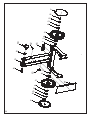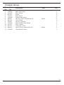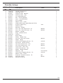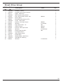
1
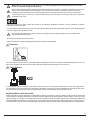
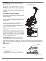
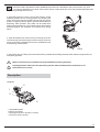
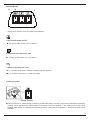
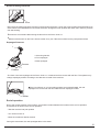
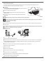
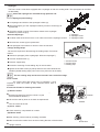
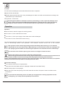
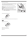
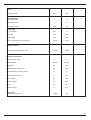
PORT A SCRUB 14 Floor Scrubber Drier Contents Instruction Manual Preface............................................................................................................... Introduction Proper Use.......................................................................................................... Notes on Warranty............................................................................................... Acceptance of the Machine................................................................................. General Safety Provisions Operation............................................................................................................ Transport............................................................................................................. Park Position....................................................................................................... Handling Mains Cable......................................................................................... Operation Machine........................................................................................................... Useful Advice for Optimum Cleaning.................................................................. Working Principle................................................................................................ First Operation Assembly............................................................................................................ Before Operation................................................................................................ Description Controls.............................................................................................................. Control Panel...................................................................................................... Detergent Infeed................................................................................................ Squeegee Governor............................................................................................ Mount / Dismount Brushes.................................................................................. Squeegee............................................................................................................ Squeegee (Initial Fitting)...................................................................................... Change Sealing Strips......................................................................................... Clean Nozzle....................................................................................................... Fill Water.............................................................................................................. Operation Operation............................................................................................................. Soiled and Fresh Water Tanks............................................................................. Electric System.................................................................................................... Technical Data..................................................................................................... Maintenance Maintenance works............................................................................................. 2 4 5 5 5 6 6 6 7 7 7 7 7 8 9 9 10 11 12 12 12 12 13 13 14 15 15 17 2 Contents Spare Parts Manual Chassis Group..................................................................................................... Handle Group...................................................................................................... Brush Drive Group............................................................................................... Brush Head Group............................................................................................... Vacuum Motor Assembly.............................................................. ....................... Vacuum Motor Group.......................................................................... ................ Squeegee Group......................................................... ........................................ Squeegee Lifting System...................................................................................... Water Feed System............................................................................................. Tank Group.......................................................................................................... Drive Group......................................................................................................... Electrical Group................................................................................................... Port A Scrub 14 Assy.......................................................................................... 21 23 25 27 29 31 33 35 37 39 41 43 47 3 Instruction Manual Preface Dear customer, It is our desire that the excellent properties of the Port A scrub 14 should justify the confidence you demonstrated by making this purchase. Before first operation of your Port A scrub 14 read these instructions carefully. They will inform you in detail about operation of the item and contains valuable information on operation, service and maintenance. Port A scrub 14 machine is an ideal machine to clean floors in small and medium areas like Offices, Hospital, Restaurant, Shopping complexes and many commercial applications. has been used in this manual at several places and identifies particular areas that are of essence for your safety. Please pass all safety instructions on to other persons operating this machine.” The symbol, has been used in this manual at several places and identifies particular areas that the operator should be cautious. The symbol, has been used in this manual at several places and identifies particular areas that the operator should note at the time of operation Prior to first operation, read the manual carefully and strictly comply with the instructions contained. Please be advised explicitly that we cannot accept any legal claims out of the contents of this manual. If repair work has to be performed, make sure that only genuine spare parts are used since genuine spare parts only may guarantee continuous and dependable operation of your machine. Valid as for JULY 2007 Minuteman International, Inc 111 South Rowling Road, Addison, IL 60101-4244, USA. Introduction Proper Use The Port A scrub 14 vacuum scrubbing machine has been exclusively designed for floor cleaning, such as wet scrubbing and vacuuming .Whatever sort of use beyond the specified range will be deemed improper use: the manufacturer can not be held liable for consequential damages. The term of proper use also includes compliance with the manufacturer’s instructions about operation, maintenance and repair. The Port A scrub 14 may be used , serviced and repaired by persons only that are familiar with the machine and are aware of possible hazards involved. The appropriate Accident Prevention Regulations as well as applicable general regulations about safety and health at work will have to be complied with. Modifications made to the Port A scrub 14 in absence of the manufacturer’s consent will relieve the manufacturer from a possible liability for consequential damage. This machine is not suitable for evacuation of dusts, which are explosive or dangerous to health. 4 Notes on Warranty The terms of the sales contract apply. Damages are not subject to warranty if they are due to non-compliance with the maintenance and service provisions. Any maintenance work has to be performed by an authorized Minuteman service workshop and confirmed in the “Maintenance certificate “which is the warranty document. The following is excluded from warranty: Natural wear and tear after overload, blown fuses and damages caused by inexpert handling and unauthorized modification of the machine. Moreover, any claim for warranty expires if damages at the machine are caused by fitting of parts or accessories without Minuteman’s prior and explicit consent or by non-compliance with the maintenance instructions. Acceptance of the machine Upon arrival, check your consignment for possible transit damage. Please have the railway authorities or the freight forwarder confirm such damage and mail your damage report and waybill to: Ours Address : Minuteman International, Inc 111 South Rowling Road, Addison, IL 60101-4244, USA. General Safety Instructions General Safety Instructions Apart from the information contained in this manual, the generally applicable legal provisions for safety and prevention of accidents must be adhered to. Do not put this manual aside without having read it, even if you did already operate similar ground cleaning equipment before. Allow yourself the time to do so in order to safe time at a later moment. The operator is responsible for all persons in the working area. Children have to keep clear of the Port A scrub 14 in operation. Nobody is allowed to stay in the zone of danger. The warning and instruction plates attached to the Port A scrub 14 give important advice about safe operation .Replace lost or illegible stickers. Before starting to work, the operator has to check that the Port A scrub 14 and its working implements are in proper and safe operating condition. Machines with known defects must not be used. It will be of essence to make yourself familiar with all accessories and controls, as well as their functions, before you start working. Avoid the mess of having to read this book while trying to run the machine. Operation Ground cleaning machines may be run by qualified personnel only; such personal will have to have evidenced their qualification for running the machine to the owner or his authorized representative; operators explicitly will have to be instructed by the owner or his authorized representative to use the machine. The machine may be used for cleaning such surfaces approved by the owner or this authorized representative. To prevent damages at the brushes as well as at the floor, do not let the Machine run dry. The machine has been exclusively designed for wet scrubbing and vacuuming. Turn the motors off, fold the support roller and the operating handle down and protect the machine against unintended movements before leaving it unattended. Use genuine spare brushes as specified by the manufacturer. Use of other than the indicated brush types may affect safety. When transporting the Port A scrub 14, shut down the motors of the working implements. The operator has to use the machine in accordance to its intended fields of application. During operation, he has to take account of the local conditions (stairs, obstacles) and of other persons, in particular to children. Turn off the machine before any passage over dormers. Use cleaning agents only, which are suitable for automatic machines (low foaming), and adhere to the instructions for use, disposal and to the precautions specified by the manufacturer of the cleaning agent. 5 Make sure to connect the Port A scrub 14 to a socket equipped with earthed protective wire and to mains of adequate voltage and frequency Never collect explosive fluids, undiluted acids and solvents! This includes e.g. gasoline, paint thinners or fuel oil, Which-when penetrating the air being taken in may form explosive vapors or mixtures; moreover acetone, Undiluted acids and solvents if they should be aggressive to the material used for the machine components. The machine may be used only on indoor hard floorings and for operation on level grounds with a maximum inclination of up to 2 % Using the machine on public roads and places is not admitted. Qualified personnel only are admitted to perform maintenance and repair work . Turn the machine off and disconnect the mains plug before cleaning and maintaining the machine, when replacing parts or when change over to another function. Do not clean the machine by means of vapour jet or high pressure cleaning equipment. Do not allow water penetrate the electrical parts. The machine is splash-water proof (IPX3). Use of the machine in areas endangered by explosion hazard is not admitted. Transport The front roller of the Port A scrub 14 has been fitted for parking the machine only and precludes damages to the floor .It is thus recommended to lift up the brush head as represented before transporting the Port A Scrub 14. Park Position Working Position Parking Position If not operated, the Machine has to be stored in its park position. This position is attained by using the support roller located at the front of the machine as represented. Actuate the support by a lever located above the support roller (see Fig.) And the brush head of the machine is lightly lifted. This is to preclude deformation of the brushes. Handling Mains cable Assembly Make sure that the mains cables are not damaged by passing over them by pinching, pulling or other impacts. Check the mains cables for ageing and damages at regular intervals. Replace them by the type ST cable 14 AWG / 3 Core (UL / CSA approved) with 15 m length. Power plug and connectors shall be rated for 125 Volts, 20 Amps (UL / CSA approved) having standard NEMA configuration for locking types as specified by the manufacturer. When replacing the coupling plug of the mains cable or when connecting lines respect the splash water protection and the tensile strength of the components. 6 Operation Port A scrub 14 Working Principle Wet cleaning of hard floorings requires equipment with squeegee and brushes suitable for the type of floor to be cleaned. The rotating brushes and the cleaning lye scrub the dirt and clean the floor thoroughly while the squeegee collects the lye immediately. The floor is dry and clean can be stepped on immediately. Useful advice for optimum cleaning Before wet cleaning, sweeping the floor is required. This is not only to improve the cleaning effect but to significantly reduce the wearing of the machine. In case of heavy soiling or for wax removal (basic cleaning), a second treatment of the floor may be required. In the first cycle, the floor is scrubbed with a detergent solution adopted to the degree of soiling. This cleaning agent acts on the floor according to the specifications of the manufacturer for about 5 to 10 minutes, then scrub the floor gain with the squeegee being lowered. Comply with the instructions for correct dosage of detergent. Correct dosage will help you save money And protect the environment. Occurrence of great quantities of foam will affect functioning of your machine. Actually, it indicates excessive dosage or improper suitability of dosing and degree of soiling. Unused detergent particles in the soiled water lead to formation of foam. Refer to the detergent reservoir for information on correct dosage. Take the manufacturer’s recommendations as a first basis. Test made by yourself in practice will help you find the ideal type of detergent and the perfect dosage applicable to it. First Operation Assembly The Port A scrub 14 is delivered in a card board box. The bottom is a wooden pallet to which the machine is fastened by plastic straps. Open the bottom side of the box and pull it upwards, then loosen the straps and take the machine from pallet. Before Operation 1. Upon delivery, the Port A scrub 14 has been secured by insulation blocks at the bottom and the top to preclude unwanted movement of the machine. After taking the machine from the pallet: Top insulation block (I) Open the cardboard box at the top side (II) Remove the insulation blocks (III) Take the Port A scrub 14 off the box and avoid any damage to the machine (IV)The operating handle of the Machine is still in its transport position. Bottom insulation block 7 CAUTION: Mains-operated machine! Qualified personnel only is admitted to open the machine; Any work such as e.g. Maintenance or repair actions at the electric components have to be executed with adequate tools only and by qualified personnel only. 2. After taking the Port A scrub 14 to its park position, set the operating handle into its working position by releasing the button at the side. After the handle has been set into service position, engage the button again to preclude the handle from displacing. After operation, the handle can be folded back again as described above. In this folded position the handle is protected against the damages and requires less storing space. 3. Open the lateral brush head cover by loosening the screw. Then insert the enclosed brushes into the housing. The Port A scrub 14 has been equipped with screws to facilitate removal and fastening of the brushes Screw 4. After folding of the lid, filling of the fresh water tank is possible. Before filling with fresh water, take the support roller out of its parking position. Make sure that all covers and flaps have been fitted before starting operation A damaged mains cable has to be replaced by specific cable available at the manufacturer or an authorized service centre. Description Controls 3 1 2 4 1.Adjustable handle 2.Button for Handle 3.Squeegee Governor (forward, reverse) 4.Screw for brush removal 8 Control panel A B C 1. Brush motor, suction motor and water pump switches A. Brush motor switch ON / OFF Function in ON if switch “A” is in position “I” B. Suction motor switch ON / OFF Function in ON if switch “B” is in position “I” C Water pump switch ON / OFF In “I” position of the switch, water is steadily pumped to the floor. In “0” position of the switch, no water is pumped. 2. Detergent infeed Pump Switch The Port A Scrub 14 allows mixing of cleaning lye and fresh water in the tank. The amount of detergent required for cleaning can be regulated by the pump switch. If the switch is set to the position “I” the cleaning lye is continuously supplied. If the solution is required by intervals only, press the switch and hold in position “I”. This function helps to save detergent. 9 Screw for fitting the Brush Screw Disconnect the mains plug before mounting or dismounting the brush. Loosen the screw for fitting the brush before use of the machine and afterwards for removal of the brush. Change the brush position after each use in order to preclude one-side wearing. Loosen the screw before dismounting the brush from the Port A Scrub 14 Dismount the brush from the Port A Scrub 14 after every use. Take the machine into the park position before Squeegee Governor 1 1.Governing handle 2.Front squeegee 3.Rear squeegee Reverse 2 Forward 3 ·The front or the rear squeegee of the Port A Scrub 14 is lowered and has contact with the floor. The operator may change squeegee position according to the direction of travel of the machine. If the port A Scrub 14 is in its working position and pushed forward, the rear squeegee has contact with the floor while the front squeegee is lifted. Water End of operation Due to the counter-rotation of the brushes, some water remains between the brushes at the end of operation. Proceed thus as follows at the end of operation - Take the machine into park position - Turn suction motor on - Move the machine a little bit forward During this movement, the rear squeegee takes in the water. 10 Mount / Dismount brushes According to the type and degree of soiling, the Port A Scrub14 can be equipped with brushes from the accessories. Refer to chapter ”Technical Data” on page 17. Mount Brush Use the support roller located at the handle side of the Port A Scrub 14 to set the machine into its park position. Brush Cover Remove screw of the brush cover. Fasten supplied brushes at the drive rollers at the inside of the opposite cover. Close brush cover such that the guiding rollers and the brushes safely catch. Brush When mounting, check the safe catching of rollers and brushes.. Before cleaning or maintaining the machine as well as before replacing parts of it, turn the machine off and disconnect the plug. Dismount Brushes Use the support roller located at the handle side of the Port A Scrub 14 to set the machine into its park position. Loosen screw. When inserting the brushes for the next operation, make sure to change position of the brush such that one- sided brush wearing is precluded. Brush maintenance 2 1 Fig. 1 Remove fresh and soiled water tanks Fig. 2 Use the support roller located at the handle side of the Port A Scrub 14 to set the machine into its park position. Use the adjustment screw to set the operating handle of the machine into vertical position, and then tilt the machine down as represented. Loosen screw and fix the brushes manually as represented in Fig. 2 in direction 1. Open brush cover in direction 2. Remove brushes Clean brush compartment Insert brushes, close brush cover and secure with screw. Set Port A Scrub 14 in upright position. Use adjustment screw to set the operating handle into working position . Set front support roller into working position. Re-insert fresh and soiled water tanks. 11 Squeegee The Port A scrub 14 has been equipped with a squeegee of 450 mm working width. The squeegees can be liftedout alternately Check the squeegee for collected foreign particles and Mount Squeegee (Initial Fitting) 3 Lift squeegee and hold it to the squeegee holders (3). Mount squeegee (1) to the squeegee holder by means of screws (2) as represented 2 Check the smooth running of the bottom sleeve at the squeegee holders for perfect hinging. Dismount Squeegee 1 Lift brush head of the Port A Scrub 14 in order to access the squeegee screws. 1.squeegee 2.squeegee screw 3.squeegee holder Remove both screws (2) as represented. Pull squeegee to the bottom to remove it from the machine. Change Sealing Strips No tools are required for dismounting the sealing strips. Proceed as follows: Dismount squeegee (refer to paragraph “Dismount squeegee” ). 3 2 1 Unscrew knurled screw (1) Remove support strip Proceed to mounting of new sealing strip in reverse order. 1. Knurled screw 2. Support strip 3. Sealing strip Tighten the knurled screws (by hand) and from the centre towards the outsides (slotted sealing strips point to the front, plain ones to the back) The rear sealing strip can be turned round if worn at the front edge. Clean nozzle The nozzle clogs after some hours of operation. It thus required to clean the nozzle at daily intervals before start of operation. Proceed as follows for cleaning the nozzle: (I) Remove nozzle Dismount brushes from the Port A Scrub 14 (see “Dismount/Mount Brushes”). Lift machine and lay down on its back as represented. Turn the nozzle to the left Loosen Tighten NOZZLE (II) Clean nozzle · Clean nozzle by compressed air or water (III) Mount nozzle · After cleaning, insert nozzle by screwing clockwise . make sure that the nozzle slot is as the mounting direction of the brushes. Upright machine Nozzle Slot 12 max. 50°C Fill water Fill fresh water and detergent as described below before start of operation. Open tank lid and fold back . Fill fresh water tank with water (50°C max.) And detergent in relation to the dirt encountered and according to the specifications by the manufacturer. Filling Amount : 10 litres max. Use detergents suitable for automatic machines (low foaming) in order to preclude damages at the suction turbine. We recommend Minuteman detergents for cleaning and care, which are perfectly adopted to the Port A Scrub 14. These products fulfil the requirements of the Detergents Act Operation Operation Use the button to take the support into working position. Turn switch “A” ON to make the brush rotate. Turn switch “C” ON to open supply of fresh water with or without detergent. Turn switch “B” ON to start suction turbine running. Turn all switches OFF after operation and remove the brushes from the Port A Scrub 14. Mount the brushes in inverse order of dismounting before next operation. This measure extends service life of the brushes. Start operation of the machine by pushing forward immediately after switching on. This measure extends Service life of the brush motor. When bushing in reverse direction lift the rear squeegee with the squeegee governor. Make sure that during the operation of the machine the mains cable always Turn the brush drive off before passing over dormers of a height of 10mm and more. Danger when passing over the mains cable with rotating brushes. Start cleaning in the socket area and clean by stripes. If the surface is not obstructed, start at borders and forward counter-clockwise. Clean the remaining surface by stripes and starting in the socket area. Divide partly obstructed surfaces into areas in the reach of the mains cable. Within shortest time, the operator will know to avoid unnecessary hindrance caused by the mains cable. At the end of cleaning: Turn machine off and set it to its park position Empty and rinse soiled water tank (see paragraph ”Soiled and Fresh Water Tanks”) Clean sealing strips of the squeegee Check the sieve at the inlet opening of the fresh water tank and clean if required in order to maintain suction performance. Do not clean the machine by means of a water jet or high-pressure cleaning equipment to avoid endangering your safety and the operability of the machine. 13 Soiled and fresh water tanks The Port A Scrub 14 is equipped with a soiled and a fresh water tank (lye tank). The filling amounts to 10 litres. Do not fill beyond the maximum mark and do not exceed a water temperature of 50°C Fresh water tank Filter Floater A suction hose delivers the soiled water into the soiled water tank. Do not take in larger amounts of secondary water (water pools) To avoid settling of residues empty and rinse the soiled And fresh water tanks after work on principle. Comply with the legal provisions for disposal of soiled Water. Check and clean the suction filter in the tank lid for soiling in regular intervals. Soiled water tank Clean soiled and fresh water tanks Slowly tilt the tank as represented to drain water before cleaning the tank Empty Soiled water tank Cap Hold the tank as represented Open the tank and drain water Close cap 14 Electric System The electric system of the Port A Scrub 14 operates at a mains voltage of 110-120V / 60Hz. G After opening the machine top, the brush motor and the suction turbine are well accessible. E F A T10A fuse (E) protects the suction turbine and has to be replaced by the same type if blown (T stands for slow-blow). The suction turbine is low-maintenance type; its carbon brushes only have to be checked after every 200 hours of operation. The brush motor is protected by a cutout (G) which can be manually reset. In case of tripped cut-out, detect the cause and remedy before re-starting the machine. E .Suction motor fuse F. Pump fuse G. Brush motor cut-out The pump is protected by a T0.5A fuse (F). Replace by the same type of fuse. Reset the cut-out by pushing down the transparent dome of the fuse box. After tripping, wait for approx. 30 seconds before resetting. In case of repeated fuse blowing detect the cause. We recommend having all work at the electric System done by qualified personnel only. Before starting work at the electric system, disconnect the mains plug. After work at the electric system is finished, proceed to a safety test Technical Data Dimensions Length mm 700 Width mm 470 Height (with closed Handle) mm 540 Working width Squeegee Scrubbing mm mm 450 350 Surface performance, Theoretical m2/h 1400 km/h 4 Driving speed Up to Weights Deadweight, dry kg 40-43 Total weight, ready to operate, wet kg 50-53 15 Wheel Rear wheel, dia mm 175 Tank capacities Fresh water tank l 10 Soiled water tank l 11 Throughput , max. l/min 0.5 Brush head No. of brushes Qty. 2 Brush dia mm 100 Brush speed rpm 780 Brush contact pressure, max.up to kg (N ) 16-19 mm Hg 60-80 Vacuum suction Nominal vacuum pressure, min. Electrical equipment Rated Current, max. Rated voltage A 14 AC/Volt 110-120 Frequency Hz 60 Nominal power, total, max. W 1340 Circuit breaker for brush motor A 9 Fuse for vacuum motor A T10 Brush motor W 600 Suction turbine W 850 Pump W 29 Fuse for Pump A T0.5 Noise level Sound pressure level db(A) 73 16 Brushes Intended Use Brush, PA Smooth floor Brush, PP Medium Smooth Floor Brush,Silicon Carbide Hard Floor Maintenance Maintenance work Compliance with our recommendations concerning maintenance work will give you the certitude always having a machine at your disposal, which is ready to work and in good operating condition. It is better to take precautions than to repair damages - and less expensive! Please contact your local contract dealer; the people there will be glad to perform that work for you. There well trained personnel and genuine spare parts are at your disposal. In case of any inquiries or orders for spare parts, please always quote the machine's serial number indicated on the nameplate. The nameplate is located at the rear side of the machine. Turn the machine off and disconnect the mains plug before cleaning or maintaining the machine. For safety reasons, secure the lifted tank lid against inadvertently closing or lowering during all cleaning or maintenance work in or at the tank. Operate the machine only with all safety devices being fitted and in protective position. Do not proceed to cleaning by hand but use appropriate tools or auxiliary means. Maintenance or repair work has to be done using appropriate tools and by qualified personnel only. For safety reasons use genuine spare parts. Before proceeding to the maintenance and/or inspection or repair works mentioned in following, execute a functional check of all operating elements and units in order to detect Eventual failures. After repair work has finished, operate the machine after having performed a safety check only. 17 Service hours Maintenance work Daily Check connections, extension cable and plug for good condition, replace defective cable X Empty and clean (rinse) soiled water tank X Check sealing strips at the squeegee for condition. X Check squeegee for collected foreign matters and clean if required X Check the floater for function X Check filter sieve of the fresh water tank and clean if required.. X Check squeegee sealing strips for wearing and replace if required. Check the brush for tight fit and wearing and replace if required. Clean brush casing by Brush X every every 50 100 200 X X X X X X X X X X Check the tank lid gasket and replace if required. X Check fresh water infeed to the brushes X Check suction motor from carbon dust and check carbon brushes for smooth operation and wearing. Replace carbon brushes if required. Clean nozzle every X Disconnect the mains plug before executing maintenance or repair work. After these works have Finished, proceed to a safety check. 18 Port A Scrub 14 Floor Scrubber Drier Spare Parts Manual 19 20 7 65 2 4 11 3 4 2 12 8 9 9 13 12 1 24 10 3 4 2 5 6 7 Chassis Group Ref. No 1 2 3 4 5 6 7 8 9 10 11 12 13 Part No 3180004 3130077 931756 3130071 3130038 829306 931128 931045 3130054 931753 931783 829203 3130062 Description Base Frame Assy Seal - W heel W heel Bush-W heel W asher-Main W heel Hex. Soc. CSK. Head Screw SS Cover W heel Hex Soc. Head Pin Bush LH&RH- Pillar Handle Knob - Handle Cover Assy - Pillar Hex.Soc.CSK. Head Screw SS Lifting Handle-Frame Size M6x16 M5x10 Qty 1 4 2 4 2 2 2 1 2 1 1 2 1 21 14 12 2 4 18 13 15 30 31 20 29 25 22 33 30 26 32 8 24 3 23 21 9 8 5 6 7 1 19 16 17 22 34 35 28 27 10 11 Handle Group Ref. No Part No 1 2 3 4 5 6 7 8 9 10 11 12 13 14 15 16 17 18 19 20 21 22 23 24 25 26 27 28 29 30 31 32 33 34 35 3180016 3180029 931281 3130120 847001 928107 925124 927095 932106 872004 931835 931776 931174 831308 828210 931183 931199 3530072 931182 931166 829306 931158 837208 931194 818104 817203 931845 836004 931134 845052 837207 931234 866050 812205 3130072 Description Handle (W eldm ent) S teering As s y S w itc h C over - B ottom S w itc h C over - T op C irc uit B reaker 9A Nut - C irc uit B reaker C ap - C irc uit B reaker F us e Holder G las s F us e - T 10A C able G land w ith S piral G uards P G 16 P ow er C able As s y S hifter As s y B rac ket - S hifter Hex. S oc . Hd C ap S c rew - S t Hex. S oc . C s k Hd S c rew - S t B ellow - Handle P lug - Handle C over S w itc h B oot C able G uide - S hifter T op Hex S oc C S K HD S c rew G uide - R ope C R P H S elf T apping S c rew - S t G rom m et - S w itc h C over C R P an Head S c rew - S S C R P an Head S c rew - S t C onnec tor - E lec . B ox C R P H S elf S c rew - S S G uide - S hifter B ottom W as her - S S C R P H S elf T apping S c rew - S t G las s F us e - T 0.5A E xternal T oothed W as her - S t C R C S K S c rew B rac ket-C hannel Size 12m M6X25 M5X35 M6X16 4.8X25 M4X12 M5X10 3.5X13 5.2X10X1.6 4.8X16 M5 M5x15 Qty 1 1 1 1 1 1 1 2 1 1 1 1 1 1 4 1 1 3 1 2 2 1 3 2 2 1 1 2 2 3 2 1 1 1 1 23 24 18 17 16 4 3 21 20 12 7 1 15 14 13 6 11 10 7 2 8 5 9 16 19 17 18 Brush Drive Group Ref. No Part No 1 2 3 4 5 6 7 8 9 10 11 12 13 14 15 16 17 18 19 20 21 3130002 3180022 931171 3180062 831306 3180053 925002 3180028 831308 844063 859068 818206 831306 844061 838060 931235 3130024 931172 3180052 3130010 845052 Description Hous ing - Brus h Hous ing As s y-Gear Support Hinge - Idler End Idler Support As s y Brus h Hex. Soc .Hd C ap Sc rew -SS Brus h Motor D rive Belt 425-5M-15-HTD C over - W ith Seal Hex-Soc -Hd-C ap-Sc rew W as her Hex. Nyloc k Nut - St C R PH-Sc rew Hex Soc Hd C ap Sc rew W as her D om ed C ap Nut-SS Lip-Flas h Guard Strip-Flas h Guard Knob-SQ G Geared Motor w ith D rive Stud-Brus h Hous ing W as her Size M6X16 M6X25 6.4X18X2 M6 M5X16 M6x16 6.4X12X1.6 M6 5.2X10X1.6 Qty 1 1 2 1 3 1 2 1 2 4 4 1 1 2 1 2 2 8 1 4 1 25 26 34 35 36 20 21 19 14 15 16 10 17 18 30 7 26 28 29 31 32 24 27 23 22 25 13 33 11 10 12 9 8 2 7 1 2 3 4 6 5 Brush Head Group Ref. No Part No 1 2 3 4 5 6 7 8 9 10 11 12 13 14 15 16 17 18 19 20 21 22 23 24 25 26 27 28 29 30 31 32 33 3130006 875010 3180008 931027 931815 831307 875011 931036 931035 854007 931129 925012 829306 3130005 931157 3130075 845101 838100 854008 931758 3130042 3130066 837207 881041 3130035 3180024 925129 3130021 829203 3130067 3130043 3130034 3180023 Description Housing-Gear Support Bearing Sprocket Assy Gear Drive Key Idler - Plain Assy Hex. Soc. Hd Cap Screw - St Bearing Gear-LH Gear-RH O' Ring Pulley-Drive W asher-Bridge Hex-Soc-CSK-Hd-Screw-SS Cover Idler End Spacer-Idler End Idler Pulley - Brush W asher-SS-304 Domed Cap Nut-SS Oring Knob Pin-Idler End Bracket-Parking W heel Self Tapping Screw Circlip Internal Pin-Parking Stand Bracket-Castor Circlip W asher-Castor Hex-Soc-CSK-Hd-Screw-SS Knob-Parking W heel W heel-Parking Pin-W heel Parking W heel Kit Size 6003 2RS M6X20 608 2Z 36X2.5 M6X16 10.5X20X2 M10 6X2.0 4.8X16 Light B22 E6.0 (Type C) M5X10 Qty 1 8 4 4 2 2 2 1 1 4 2 4 4 1 2 2 2 2 1 1 2 1 2 1 1 1 1 1 1 1 1 1 1 OPTIONAL 34 35 36 931892 931893 931894 Brush (PA / Blue) Brush (PP / Black) Brush (SIC / Grey) 2 2 2 27 28 Vacuum Motor Assembly Ref. No Part No 1 2 3 4 5 6 7 8 3130046 931197 931857 3130047 845052 837210 836004 3180032 Description Hs g B ottom - V.M Gas ket - V.M V.M w ith C onnec tor As s y Hs g Top - V.M W as her - S S 304 S elf Tap S c rew C R P H S elf S c rew - S t W ire As s y - V.M C apac itor Size 5.2X10X1.6 4.8X13 3.5X13 Qty 1 2 1 1 10 10 1 1 29 7 6 HOLDER-LOAT 10 16 15 8 5 4 9 3 2 1 11 12 11 13 11 12 11 13 TANK-COLLECTION 14 14 SQUEEGEE-REAR SQUEEGEE-FRONT 30 Vacuum Motor Group Ref. No Part No 1 2 3 4 5 6 7 8 9 10 11 12 13 14 15 16 836206 845039 931132 931810 931196 931850 931851 3180054 931204 3180044 881056 931191 931184 931054 844043 818104 Description C R PH Self Tapping Sc rew - SS W as her - SS Guide - Float Float Gas ket - Float Hos e As s y - Vac uum Hos e As s y - C ollec tion Vac uum Motor Sub As s y Gas ket - Lip Hos e As s y SQ G Group C able tie Blac k Lip - Valve Bellow - Sqg R ing - Bellow W as her - SS C R PH Sc rew Size 3.5X16 4.0X8.0X0.5 292 m m 4.3X12X1.0 M4X12 Qty 4 4 1 1 1 1 1 1 2 1 4 2 2 6 2 2 31 32 15 SQUEEGEE-FRONT 1 18 17 16 9 20 19 8 7 13 12 14 10 11 21 3 2 6 4 21 5 SQUEEGEE-REAR 1 Squeegee Group Ref. No Part No 1 2 3 4 5 6 7 8 9 10 11 12 13 14 15 16 17 18 19 20 21 3130051 931170 931126 832213 931233 931224 3130022 931172 3180012 3130048 931175 931050 3130049 931251 3130063 931146 931147 841108 931841 837210 845052 Description B ody S qg Valve Top Valve B ottom Hex. S oc . Hd C ap S c rew - S S Lip - S qg. Inner Lip - S qg. O uter S trip - Lip S qg K nob - S qg S queegee R od S ub As s y Guide - P illar S qg B us h Top - P illar S qg. P in 10 - P illar S qg B us h B ottom - Pillar S qg S pring - P illar S qg. Loc king C lip-S Q G P illar D eflec tor - R oller W as her - D eflec tor C S K -S elf-S c rew W heel - S qg. As s y C R P H-S elf-S c rew -S S W as her - S S Size M5X50 4.8X13 4.8X13 5.2X10X1.6 Qty 2 2 2 2 2 2 4 20 4 4 4 4 4 4 4 4 4 4 4 8 4 33 23 11 21 12 19 18 7 10 5 5 5 5 5 5 5 15 14 13 9 20 22 6 17 8 16 1 2 4 3 34 Squeegee Lifting System Ref. No 1 2 3 4 5 6 7 8 9 10 11 12 13 14 15 16 17 18 19 20 21 22 23 Part No 931181 931051 3180013 3180014 931804 3180027 3180026 831323 3130053 931109 844061 859068 828208 3130052 931107 3130061 822058 3130018 822068 3130019 931252 803308 931819 Description C lip - C lam p P in 6 - P illar S qg S queegee Front S queegee R ear C able As s y - S queegee S qg R od As s y - Front S qg. R od As s y - R ear Hex. S oc ket Head C ap S c rew - S t B us h-S Q G Link - 75 W as her - S t Hex. Nyloc k Nut - S t Hex-S oc -C S K -Hd-S c rew B us h9.8-S Q G Link - 50 U B rac ket - S tud Hex-Nut S tud - Link Adj Hex-Nut C onnec tor - Link Hook - S pring Hex Head S c rew S hifting Lever As s y Size M6X18 6.4X12X1.6 M6 M5X25 M5 M6 M6X25 Qty 4 4 1 1 1 1 1 2 4 1 7 4 1 1 1 1 3 1 4 1 1 1 1 35 36 Water Feed System Ref. No Part No 1 2 3 4 5 6 7 8 9 10 11 12 13 14 15 16 17 931142 931198 931816 931143 3130113 925325 3130111 928054 3130116 836004 3130112 3180063 931290 928062 928063 3130074 931809 Description Holder - Noz z le W as her - Noz z le Noz z le As s y Nut - Noz z le Vibrating Pad-Pum p Vibrating Pum p C onnec tor-Pum p Support R ing Hos e - Noz z le C R PH Self Sc rew - SS C lam p-Pum p Pum p As s y 115V 60Hz Hos e - Pum p Body-Filter Filter C ap-Filter Filter As s y Size 3.5X13 L= 875.0±5.0 Qty 1 1 1 1 2 1 1 1 1 1 1 1 1 1 1 1 1 37 38 Tank Group Ref. No 1 2 3 4 5 6 7 8 9 10 11 12 13 14 15 16 17 18 19 20 21 22 23 24 25 26 27 Part No 3130117 931125 931144 836206 931162 3130068 836004 931159 812104 3180057 3130119 3130060 3130050 3180059 3130118 3130058 931203 3180058 931216 931145 931156 931265 931264 3180046 3180060 845039 836003 Description Bottom Hous ing C ap - V.M Yoke Hinge - Lid (R ight) C R PH Self Sc rew -SS Yoke Hinge - Lid (Left) Mounting Plate - Bot. Hs g C R PH Self Sc rew - SS Brac ket - Hous ing C R C SK Sc rew - St Bottom Hous ing As s y Tank - Fres h Handle - Fres h Spac er - Tank Tank - Fres h as s y Tank - C ollec tion Handle - C ollec tion C ap - C ollec tion Tank Tank - C ollec tion As s y Lid Hook Hinge - Lid Hos e Guide Gas ket - Fres h Gas ket - C ollec tion Holder Float As s em bly Top C over As s y W as her -SS C R PH Self Tapping Sc rew -SS Size 3.5X16 3.5X13 M4X12 4.0X8.0X0.5 3.5X9.5(D IN 7981) Qty 1 1 1 12 1 2 8 2 4 1 1 1 4 1 1 1 1 1 1 2 2 1 1 1 1 6 2 39 40 Drive Group Ref. No 1 2 3 4 5 Part No 3130040 844061 831307 845041 818105 Description Size Support Plate-Hous ing W as her Hex Soc Hd C ap Sc rew W as her-SS C R Pan Head-SS 6.4X12X16 M6X20 4.3X9X0.8 M4X15 Qty 4 4 4 2 2 41 42 Electrical Group Ref. No 1 2 3 4 5 6 7 8 9 10 11 12 13 14 Part No 3130055 931150 836006 931195 931844 931123 931876 931875 841106 841103 835002 845052 866050 822058 Description B as e - Term inal C over - Term inal C R P H S elf S c rew - S S Grom m et - Term inal C onnec tor - P illar B rac ket - C apac itor C apac itor - 150-200µF as s y C apac itor - 60µF as s y C S K S elf S c rew C R C S K Head S elf S c rew - S t C R P H S elf S c rew - S t W as her - S S E xternal Toothed W as her - S t Hex Nut Size 3X16 150-200 µF 60µF 4.2X16 4X10 2.9X9.5 5.2X10X1.6 M5 M5 Qty 1 1 2 1 1 1 1 1 4 2 2 2 1 1 43 -X3 18 -S1 -S2 -S3 19 24 16 17 15 -F2 -F1 -X1 -F3 -X2 -C3 -C1 -C2 22 -M2.X4 20 21 -M2 -M1 44 -M3 23 Electrical Group Ref. No Part No 15 16 17 18 19 20 21 22 23 24 931874 931863 931864 931865 931866 931895 931868 931878 931870 931871 Description 7Core cable assy Wire Assy - (S2 to F2) Wire Assy - (S1 to F1) Wire Assy - (X3 to S1, S2 & S3 +VE) Wire Assy - (X3 to S1, S2 & S3 -VE) 2 Core cable assy (Pump) Earth cable assy (BM) Earth cable assy (VM) Earth cable assy (Connector) Wire Assy-(S3 TO F3) Size Qty 1 1 1 1 1 1 1 1 1 1 45 1 46 2 Port A Scrub 14 Assy Ref. No Part No 1 2 925012 829307 Description W as her-Bridge Hex Soc C SK Hd Sc rew -SS Size M6X20 Qty 2 2 47 LIMITED WARRANTY Minuteman International, Inc. warrants to the original purchaser/user that this product is free from defects in workmanship and materials under normal use and service for a period of one year from date of purchase. In addition, Minuteman International, Inc will, at its option, honor labor warranty claims for the first 6 months from date of sale, provided such claims are submitted through and approved by factory authorized repair stations. Minuteman International, Inc will, at its option, repair or replace without charge, except for transportation costs, parts that fail under normal use and service when operated and maintained in accordance with the applicable operation and instruction manuals. This warranty does not apply to normal wear, or to items whose life is dependent on their use and care, such as belts, cords, switches, hoses, rubber parts, electrical motor components or adjustments. Parts not manufactured by Minuteman International, Inc such as engines, batteries, battery chargers, hydraulic pumps, and tires are covered by and subject to the warranties and/or guarantees of their manufacturers. Please contact Minuteman International, Inc for procedures in warranty claims against these manufacturers. Special warning to purchaser - Use of replacement filters and / or pre-filters not manufactured by Minuteman International, Inc. or its designated licensees will void all warranties expressed or implied. A potential health hazard exists without exact original equipment replacement. All warranted items become the sole property of Minuteman International, Inc. or its original manufacturer, whichever the case may be. Minuteman International, Inc. disclaims any implied warranty, including the warranty of merchantability and the warranty of fitness for a particular purpose. Minuteman International Inc. assumes no responsibility for any special, incidental or consequential damages. This limited warranty is applicable only on the U.S.A. and Canada, and is extended only to the original user / purchaser of this product. Customers outside the U. S. A and Canada should contact their local distributor for export warranty policies. Minuteman International Inc. is not responsible for costs or repairs performed by persons other than those specifically authorized by Minuteman International, Inc. This warranty does not apply to damage from transportation, alterations by unauthorized person, misuse or abuse of the equipment, use of non-compatible chemicals, or damage to property, or loss of income due to malfunctions of the product. If a difficulty develops with this machine, you should contact the dealer from whom it was purchased. This warranty gives you specific legal rights, and you may have other rights, which vary from state to state. Some states do not allow the exclusion of limitation of special, incidental or consequential damages, or limitations on how long an implied warranty lasts, so the above exclusions and limitations may not apply to you. World Headquarters Minuteman International, Inc. 111 South Rohlwing Road Addison, Illinois 60101 (630) 627-6900 FAX (630) 627-1130 Minuteman Canada, Inc. 2210 Drew Road, Mississauga, Ontario L5S 1B1 (905) 673-3222 FAX (905) 673-5161 3130101 Rev A 06/07 Printed in U.S.A