1
OC261-B--1.qxp
03.2.19 3:07 PM
Page 1
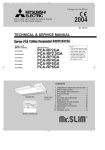
SPLIT-TYPE, HEAT PUMP AIR CONDITIONERS
SPLIT-TYPE, AIR CONDITIONERS
No.OC261
REVISED EDITION-B
TECHNICAL & SERVICE MANUAL
R407C
Outdoor unit
[model names]
PUH-P1VGAA
Service Ref. is on page 2.
PUH-P1.6VGAA
PU-P1.6VGAA
PUH-P1.6YGAA
PU-P1.6YGAA
PUH-P2VGAA
PU-P2VGAA
PUH-P2YGAA
PU-P2YGAA
PUH-P2.5VGAA
PU-P2.5VGAA
PUH-P2.5YGAA
PU-P2.5YGAA
PUH-P3VGAA
PU-P3VGAA
PUH-P3YGAA
PU-P3YGAA
PUH-P4VGAA
PU-P4VGAA
PUH-P4YGAA
PU-P4YGAA
PUH-P5YGAA
PU-P5YGAA
PUH-P6YGAA
PU-P6YGAA
Revision:
• [PUH-5, 6YGAA1.UK PU-5, 6YGAA1.UK]
TECHNICAL CHANGES, SPECIFICATIONS,
DATA and PARTS LIST have been partially
modified.
COMPRESSOR CONVERSION KIT(TFD-230)
has been added to the PARTS LIST(page 69).
• Please void OC261 REVISED EDITION-A.
CONTENTS
1. TECHNICAL CHANGES·································3
2. SAFETY PRECAUTION··································4
3. COMBINATION OF INDOOR AND OUTDOOR UNITS···6
4. PART NAMES AND FUNCTIONS ··················7
5. SPECIFICATIONS···········································8
6. DATA ·····························································15
7. OUTLINES AND DIMENSIONS····················18
8. WIRING DIAGRAM ·······································22
9. WIRING SPECIFICATIONS ··························26
10. REFRIGERANT SYSTEM DIAGRAM··············27
11. TROUBLESHOOTING···································31
12. DISASSEMBLY PROCEDURE ·····················36
13. PARTS LIST ··················································40
14. OPTIONAL PARTS························Back Cover
Model name indication
OC261-B--1.qxp
03.2.19 3:07 PM
Page 2
[Service Ref.]
PUH-P1VGAA.UK
PUH-P1.6VGAA.UK
PUH-P1.6YGAA.UK
PUH-P2VGAA.UK
PUH-P2YGAA.UK
PUH-P2.5VGAA.UK
PUH-P2.5YGAA.UK
PUH-P3VGAA.UK
PUH-P3YGAA.UK
PUH-P4VGAA.UK
PUH-P4YGAA.UK
PUH-P5YGAA.UK
PUH-P6YGAA.UK
PU-P1.6VGAA.UK
PU-P1.6YGAA.UK
PU-P2VGAA.UK
PU-P2YGAA.UK
PU-P2.5VGAA.UK
PU-P2.5YGAA.UK
PU-P3VGAA.UK
PU-P3YGAA.UK
PU-P4VGAA.UK
PU-P4YGAA.UK
PU-P5YGAA.UK
PU-P6YGAA.UK
PUH-P1VGAA1.UK
PUH-P1.6VGAA1.UK
PUH-P1.6YGAA1.UK
PUH-P2VGAA1.UK
PUH-P2YGAA1.UK
PUH-P2.5VGAA1.UK
PUH-P2.5YGAA1.UK
PUH-P3VGAA1.UK
PUH-P3YGAA1.UK
PUH-P4VGAA1.UK
PUH-P4YGAA1.UK
PUH-P5YGAA1.UK
PUH-P6YGAA1.UK
PU-P1.6VGAA1.UK
PU-P1.6YGAA1.UK
PU-P2VGAA1.UK
PU-P2YGAA1.UK
PU-P2.5VGAA1.UK
PU-P2.5YGAA1.UK
PU-P3VGAA1.UK
PU-P3YGAA1.UK
PU-P4VGAA1.UK
PU-P4YGAA1.UK
PU-P5YGAA1.UK
PU-P6YGAA1.UK
2
OC261-B--1.qxp
1
03.2.19 3:07 PM
Page 3
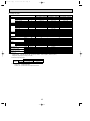
TECHNICAL CHANGES
(REVISED EDITION-A)
PUH-P1, 1.6, 2, 2.5, 3, 4VGAA.UK ➔ PUH-P1, 1.6, 2, 2.5, 3, 4VGAA1.UK
PUH-P1.6, 2, 2.5, 3, 4YGAA.UK
➔ PUH-P1.6, 2, 2.5, 3, 4YGAA1.UK
PU-P1.6, 2, 2.5, 3, 4VGAA.UK
➔ PU-P1.6, 2, 2.5, 3, 4VGAA1.UK
PU-P1.6, 2, 2.5, 3, 4YGAA.UK
➔ PU-P1.6, 2, 2.5, 3, 4YGAA1.UK
● Strainer (#50) for stop valve of liquid pipe side and Filter Drier are not used.
(REVISED EDITION-A)
PUH-P1, 1.6, 2, 2.5, 3, 4VGAA.UK
➔ PUH-P1, 1.6, 2, 2.5, 3, 4VGAA1.UK
PUH-P1.6, 2, 2.5, 3, 4, 5, 6YGAA.UK ➔ PUH-P1.6, 2, 2.5, 3, 4, 5, 6YGAA1.UK
PU-P1.6, 2, 2.5, 3, 4VGAA.UK
➔ PU-P1.6, 2, 2.5, 3, 4VGAA1.UK
PU-P1.6, 2, 2.5, 3, 4, 5, 6YGAA.UK
➔ PU-P1.6, 2, 2.5, 3, 4, 5, 6YGAA1.UK
● Microcomputer of Outdoor Controller Board has changed since Filter Drier is not used.
(The limit of discharging temperature has been added.)
(REVISED EDITION-A)
PUH-P5YGAA.UK ➔ PUH-P5YGAA1.UK
● The method of connecting the Compressor’s terminals has changed from Faston type to
Screw type.
(REVISED EDITION-B)
PUH-P5YGAA1.UK
PUH-P6YGAA1.UK
PU-P5YGAA1.UK
PU-P6YGAA1.UK
● Compressor has changed due to the change in refrigerant oil.
Refrigerant oil : 3MA-POE ➔ 3MAW-POE
Compressor model : ZR61KCE-TFD-522 ➔ ZR61KCW-TFD-522
ZR72KCE-TFD-522 ➔ ZR72KCW-TFD-522
3
OC261-B--1.qxp
2
03.2.19 3:07 PM
Page 4
SAFETY PRECAUTION
Cautions for using with the outdoor unit which adopts R407C refrigerant.
· Do not use the existing refrigerant piping.
-The old refrigerant and refrigerant oil in the existing piping contains a large amount of chlorine which may cause the refrigerant oil of the new unit to deteriorate.
· Do not use copper pipes which are broken, deformed or discolour .
In addition, be sure that the inner surfaces of the pipes are clean, free of hazardous sulphur and oxides, or have no dust /
dirt, shaving particles, oils, moisture or any other contamination.
-If there is a large amount of residual oil (hydraulic oil, etc.) inside the piping and joints, deterioration of the refrigerant oil will
result.
· Store the piping to be used during installation indoors and keep both ends of the piping sealed until just before
brazing. (Store elbows and other joints in a plastic bag.)
-If dust, dirt, or water enters the refrigerant cycle, deterioration of the oil and compressor trouble may result.
· Use ester oil, ether oil or alkyl benzene (small amount) as the refrigerant oil to coat flares and flange connections.
-The refrigerant oil will degrade if it is mixed with a large amount of mineral oil.
Use liquid refrigerant to fill the system.
-If gas refrigerant is used to fill the system, the composition of the refrigerant in the cylinder will change and performance
may drop.
· Do not use a refrigerant other than R407C.
-If another refrigerant (R22, etc.) is used, the chlorine in the refrigerant may cause the refrigerant oil to deteriorate.
· Use a vacuum pump with a reverse flow check valve.
-The vacuum pump oil may flow back into the refrigerant cycle and cause the refrigerant oil to deteriorate.
· Do not use the following tools that are used with conventional refrigerant.
(Gauge manifold , charge hose, gas leak detector, reverse flow check valve, refrigerant charge base, vacuum gauge,
refrigerant recovery equipment)
-If the conventional refrigerant and refrigerant oil are mixed in the R407C, the refrigerant may deteriorated.
-If water is mixed in the R407C, the refrigerant oil may deteriorate.
-Since R407C does not contain any chlorine, gas leak detectors for conventional refrigerant will not react to it.
· Do not use a charging cylinder.
-Using a charging cylinder may cause the refrigerant to deteriorate.
· Be especially careful when managing the tools.
-if dust, dirt, or water gets in the refrigerant cycle, the refrigerant may deteriorate.
· Do not use the drier which is sold in the field.
-The drier for R407C refrigerant is pre-attached to outdoor unit refrigerant circuit.
-Some drier in the field are not in conformity with R407C refrigerant.
4
OC261-B--1.qxp
03.2.19 3:07 PM
Page 5
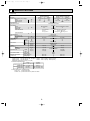
[1] Service tools
Use the below service tools as exclusive tools for R407C refrigerant.
No.
1
Tool name
Specifications
Gauge manifold
·Only for R407C.
·Use the existing fitting SPECIFICATIONS. (UNF7/16)
·Use high-tension side pressure of 3.43MPa·G or over.
2
Charge hose
3
Electronic scale
4
Gas leak detector
·Use the detector for R407C.
5
Adapter for reverse flow check.
·Attach on vacuum pump.
6
Refrigerant charge base.
7
Refrigerant cylinder.
·Only for R407C.
·Use pressure performance of 5.10MPa·G or over.
·For R407C
·Top of cylinder (Brown)
·Cylinder with syphon
8
Refrigerant recovery equipment.
[2] Notice on repair
·After recovering the all refrigerant in the unit, perform repair work.
·Do not release refrigerant in the air.
·After completing the repair work, recharge the specified amount of liquid refrigerant.
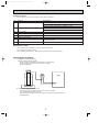
[3] Refrigerant recharging
(1) Refrigerant recharging process
1Direct charging from the cylinder.
·R407C cylinder are available on the market has a syphon pipe.
·Leave the syphon pipe cylinder standing and recharge it.
(By liquid refrigerant)
Unit
Gravimeter
(2) Recharge in refrigerant leakage case
·After recovering the all refrigerant in the unit, proceed to working.
·Do not release the refrigerant in the air.
·After completing the repair service, recharge the cycle with the specified amount of
liquid refrigerant.
5
OC261-B--1.qxp
3
03.2.19 3:07 PM
Page 6
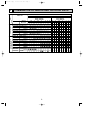
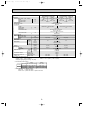
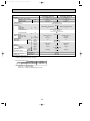
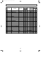
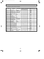
COMBINATION OF INDOOR AND OUTDOOR UNITS
Outdoor unit
Indoor unit
Heat pump without
electric heater or
Cooling only
Heat pump with
electric heater
Service Ref.
PEHD-P·EAH
PCH-P·GAH1
PKH-P·GALH1
PKH-P·FALH2
PSH-P·GAH1
PLH-P·KAH1.UK
PLH-P·AAH1.UK
PEAD-P·EA
PCA-P·GA1
PKA-P·GAL1
PKA-P·FAL2
PSA-P·GA1
PLA-P·KA1.UK
PLA-P·AA1.UK
PMH-P·BA1
PMH-P·BA2
PCA-P·HA
Service
Manual No.
MEE 01K048
OC182 REVISED
EDITION-B
OC176 REVISED
EDITION-B
OC175 REVISED
EDITION-B
OC212 REVISED
EDITION-A
OC235 REVISED
EDITION-A
OC236 REVISED
EDITION-A
MEE 01K048
OC182
OC176 REVISED
EDITION-B
OC175 REVISED
EDITION-B
OC212 REVISED
EDITION-B
OC240 REVISED
EDITION-A
OC241 REVISED
EDITION-A
OC238 REVISED
EDITION-A
OC279 REVISED
EDITION-B
OC289
Heat pump type
1
V
PUH-P • GAA.UK
PUH-P • GAA1.UK
2
2.5
3
1.6
V
Y
Cooling only type
V
Y
V
Y
V
Y
4
V
5 6
Y
Y
Y
1.6
V
Y
PU-P • GAA.UK
PU-P • GAA1.UK
2
2.5
3
V Y
V
Y
V
Y
4
V
5 6
Y
Y
Y
—
— — — — — — — — — — — —
— — —
— — — — — — — — — — — —
—
— — — — — — — — — — — — — — — — — — — —
— — — — —
— — — — — — — — — — — — — —
— — — — — — —
—
— — — — — — — — — — — —
— — — — — — — — — — — — — — — — — —
— — — — — — —
— — — — — — — — — — — —
—
— — —
—
— —
— — — — — — — —
— — — — —
— — — — — — — —
— — — — — —
— — — — — — —
—
— —
— — — — — —
— — — — — —
— — — — — — —
— — — — — —
— — — — — —
— — — — — — — — — — — — — — — — — — — —
— — — — — — — — — — — — — — — — — — — —
— — — — — — —
— —
6
— — — — — — —
— —
—
OC261-B--1.qxp
03.2.19 3:07 PM
4
Page 7
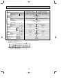
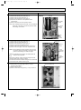
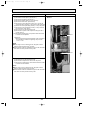
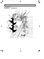
PART NAMES AND FUNCTIONS
Air outlet
(Expels warm air during cooling)
Air outlet
Air intake
Air intake
PUH-P1VGAA.UK
PU(H)-P1.6VGAA.UK
PU(H)-P1.6YGAA.UK
PUH-P1VGAA1.UK
PU(H)-P1.6VGAA1.UK
PU(H)-P1.6YGAA1.UK
PU(H)-P2VGAA.UK
PU(H)-P2.5VGAA.UK
PU(H)-P3VGAA.UK
PU(H)-P2VGAA1.UK
PU(H)-P2.5VGAA1.UK
PU(H)-P3VGAA1.UK
PU(H)-P2YGAA.UK
PU(H)-P2.5YGAA.UK
PU(H)-P3YGAA.UK
PU(H)-P2YGAA1.UK
PU(H)-P2.5YGAA1.UK
PU(H)-P3YGAA1.UK
Air outlet
Air outlet
Air intake
Air intake
PU(H)-P4VGAA.UK
PU(H)-P4YGAA.UK
PU(H)-P4VGAA1.UK
PU(H)-P4YGAA1.UK
PU(H)-P5YGAA.UK
PU(H)-P6YGAA.UK
PU(H)-P5YGAA1.UK
PU(H)-P6YGAA1.UK
CHARGELESS SYSTEM
PRE-CHARGED REFRIGERANT IS SUPPLIED FOR PIPING LENGTH AT SHIPMENT.
(Max.20m(PU(H)-P1~P2.5) / 30m(PU(H)-P3~P6))
The refrigerant circuit with LEV(Linear Expansion Valve) and a large accumulator always control the optimal refrigerant
level regardless of the length (20/30m max. and 5m min.) of piping. The additional refrigerant charging work during
installation often causes problems. Heretofore it is completely eliminated. This unique system improves the quality
and reliability of the work done.It also helps to speed up the installation time.
7
OC261-B--1.qxp
5
03.2.19 3:07 PM
Page 8
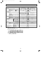
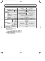
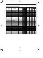
SPECIFICATIONS
1. Heat pump
OUTDOOR UNIT
Service Ref.
Function
Power supply (phase, cycle, voltage)
Input
Running current
Starting current
External finish
Refrigerant control
Compressor
Model
Motor output
Starter type
Protection devices
Crankcase heater
Heat exchanger
Fan
Fan(drive) o No.
Fan motor output
Airflow
Defrost method
Noise level
REFRIGERANT PIPING
Dimensions
Weight
Refrigerant
Charge
Oil (Model)
Pipe size O.D.
Connection method
Between the indoor &
outdoor unit
kW
A
A
kW
PUH-P1.6VGAA / YGAA.UK
PUH-P1VGAA.UK
PUH-P1.6VGAA1 / YGAA1.UK
PUH-P1VGAA1.UK
Heating
Cooling
Heating
Cooling
Single,50Hz,220-230-240V
Single,50Hz,220-230-240V / 3-ph,50Hz,380-400-415V
1.02
1.59
1.64
1.11
4.52
7.36 / 2.49
7.59 / 2.56
4.92
30
36/20
Munsell 5Y 7/1
Linear Expansion Valve
Hermetic
RE189VHSMT
RE277VHSMT/RE277YFKM
0.9
1.3
Line start
Internal thermostat
HP switch
Discharge thermo
W
kW
K/min(CFM)
Internal thermostat
HP switch
Discharge thermo
Thermal relay
HP switch
Discharge thermo
30
Plate fin coil
Propeller (direct) o 1
0.07
45(1,590)
45(1,590)
Reverse cycle
Cooling
Heating
W
D
H
46
48
dB
dB
mm(in.)
mm(in.)
mm(in.)
kg(lbs)
47
49
900(35-7/16)
330+20(13+3/4)
650(25-5/8)
50(110)
55(121)
R407C
kg(lbs)
L
mm(in.)
mm(in.)
Liquid
Gas
Indoor side
Outdoor side
Height difference
Piping length
1.7(3.8)
2.5(5.5)
0.57(Ester)MEL56
6.35(1/4)
12.7(1/2)
9.52(3/8)
15.88(5/8)
Flared
Flared
Max. 30m
Max. 30m
Notes1. Rating Conditions (ISO T1)
Cooling : Indoor : D.B. 27˚C(80˚F), W.B. 19˚C(66˚F) Outdoor : D.B. 35˚C(95˚F), W.B. 24˚C(75˚F)
Heating : Indoor : D.B. 20˚C(68˚F)
Outdoor : D.B. 7˚C(45˚F), W.B. 6˚C(43˚F)
Refrigerant piping length (one way) : 5m (16ft)
2. Guaranteed operating range
Indoor
Outdoor
D.B. 46˚C
Upper limit D.B. 35˚C, W.B. 22.5˚C
Cooling
D.B. -5˚C
Lower limit D.B. 19˚C, W.B. 15˚C
Upper limit
D.B. 28˚C
D.B. 24˚C, W.B. 18˚C
Heating
Lower limit
D.B. 17˚C
D.B. -11˚C, W.B. -12˚C
3. Above data based on indicated voltage
Indoor Unit
1 phase 240V 50Hz
Outdoor Unit 1 phase 240V 50Hz / 3 phase 415V 50Hz
8
Max. 40m
Max. 40m
OC261-B--1.qxp
03.2.19 3:07 PM
Page 9
OUTDOOR UNIT
Service Ref.
Function
Power supply (phase, cycle, voltage)
Input
Running current
Starting current
External finish
Refrigerant control
Compressor
Model
Motor output
Starter type
Protection devices
Crankcase heater
Heat exchanger
Fan
Fan(drive) o No.
Fan motor output
Airflow
Defrost method
Noise level
REFRIGERANT PIPING
Dimensions
Weight
Refrigerant
Charge
Oil (Model)
Pipe size O.D.
Connection method
Between the indoor &
outdoor unit
kW
A
A
kW
PUH-P2VGAA / YGAA.UK
PUH-P2.5VGAA / YGAA.UK
PUH-P2VGAA1 / YGAA1.UK
PUH-P2.5VGAA1 / YGAA1.UK
Heating
Heating
Cooling
Cooling
Single, 50Hz, 220-230-240V/3-ph, 50Hz, 380-400-415V(4wires)
2.68
2.36
2.77
2.29
11.51 / 4.34
10.57 / 3.82
11.90 / 4.48
10.26 / 3.70
77 / 35
62 / 31
Munsell 5Y 7/1
Linear Expansion Valve
Hermetic
NE41VMJMT / NE41YEKMT
NE36VMJMT / NE36YEKMT
1.9
1.6
Line start
Internal thermostat
HP switch
Discharge thermo
W
38
Plate fin coil
Propeller (direct) o 1
0.07
kW
K/min(CFM)
Cooling
Heating
W
D
H
Thermal relay
HP switch
Discharge thermo
55(1,940)
50(1,770)
Reverse cycle
48
dB
dB
mm(in.)
mm(in.)
mm(in.)
kg(lbs)
49
50
900(35-7/16)
330+20(13+3/4)
855(33-5/8)
71(157)
82(181)
R407C
kg(lbs)
L
mm(in.)
mm(in.)
2.6(5.7)
3.1(6.8)
1.2 (Ester)MEL56
9.52(3/8)
15.88(5/8)
Flared
Flared
Liquid
Gas
Indoor side
Outdoor side
Height difference
Piping length
Max. 40m
Max. 40m
Notes1. Rating Conditions (ISO T1)
Cooling : Indoor : D.B. 27˚C(80˚F), W.B. 19˚C(66˚F) Outdoor : D.B. 35˚C(95˚F), W.B. 24˚C(75˚F)
Heating : Indoor : D.B. 20˚C(68˚F)
Outdoor : D.B. 7˚C(45˚F), W.B. 6˚C(43˚F)
Refrigerant piping length (one way) : 5m (16ft)
2. Guaranteed operating range
Indoor
Outdoor
D.B. 46˚C
Upper limit D.B. 35˚C, W.B. 22.5˚C
Cooling
D.B. -5˚C
Lower limit D.B. 19˚C, W.B. 15˚C
Upper limit
D.B. 28˚C
D.B. 24˚C, W.B. 18˚C
Heating
Lower limit
D.B. 17˚C
D.B. -11˚C, W.B. -12˚C
3. Above data based on indicated voltage
Indoor Unit
1 phase 240V 50Hz
Outdoor Unit 1 phase 240V 50Hz / 3 phase 415V 50Hz
9
Max. 50m
Max. 50m
OC261-B--1.qxp
03.2.19 3:07 PM
Page 10
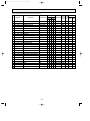
OUTDOOR UNIT
Service Ref.
Function
Power supply (phase, cycle, voltage)
Input
Running current
Starting current
External finish
Refrigerant control
Compressor
Model
Motor output
Starter type
Protection devices
Crankcase heater
Heat exchanger
Fan
Fan(drive) o No.
Fan motor output
Airflow
Defrost method
Noise level
REFRIGERANT PIPING
Dimensions
Weight
Refrigerant
Charge
Oil (Model)
Pipe size O.D.
Connection method
Between the indoor &
outdoor unit
kW
A
A
kW
PUH-P4VGAA / YGAA.UK
PUH-P3VGAA / YGAA.UK
PUH-P4VGAA1 / YGAA1.UK
PUH-P3VGAA1 / YGAA1.UK
Heating
Heating
Cooling
Cooling
Single, 50Hz, 220-230-240V/3-ph, 50Hz, 380-400-415V(4wires)
3.62
3.48
3.43
3.27
16.58 / 5.86
15.76 / 5.63
15.71 / 5.55
14.81 / 5.29
99 / 49
93 / 47
Munsell 5Y 7/1
Linear Expansion Valve
Hermetic
NE56VNJMT / NE56YDKMT
NE52VNJMT / NE52YDKMT
2.7
2.5
Line start
Internal thermostat
HP switch
Discharge thermo
W
kW
K/min(CFM)
Thermal relay
HP switch
Discharge thermo
38
Plate fin coil
Propeller (direct) o 1
0.07
50(1,770)
Propeller (direct) o 2
0.07+0.07
85(3,000)
Reverse cycle
Cooling
Heating
W
D
H
dB
dB
mm(in.)
mm(in.)
mm(in.)
kg(lbs)
49
51
51
53
900(35-7/16)
330+20(13+3/4)
855(33-5/8)
82(181)
1,260(49-5/8)
96(212)
R407C
kg(lbs)
L
mm(in.)
mm(in.)
Liquid
Gas
Indoor side
Outdoor side
Height difference
Piping length
3.3(7.3)
4.0(8.8)
1.3 (Ester)MEL56
9.52(3/8)
15.88(5/8)
19.05(3/4)
Flared
Flared
Max. 50m
Max. 50m
Notes1. Rating Conditions (ISO T1)
Cooling : Indoor : D.B. 27˚C(80˚F), W.B. 19˚C(66˚F) Outdoor : D.B. 35˚C(95˚F), W.B. 24˚C(75˚F)
Heating : Indoor : D.B. 20˚C(68˚F)
Outdoor : D.B. 7˚C(45˚F), W.B. 6˚C(43˚F)
Refrigerant piping length (one way) : 5m (16ft)
2. Guaranteed operating range
Indoor
Outdoor
D.B. 46˚C
Upper limit D.B. 35˚C, W.B. 22.5˚C
Cooling
D.B. -5˚C
Lower limit D.B. 19˚C, W.B. 15˚C
Upper limit
D.B. 28˚C
D.B. 24˚C, W.B. 18˚C
Heating
Lower limit
D.B. 17˚C
D.B. -11˚C, W.B. -12˚C
3. Above data based on indicated voltage
Indoor Unit
1 phase 240V 50Hz
Outdoor Unit 1 phase 240V 50Hz / 3 phase 415V 50Hz
10
OC261-B--1.qxp
03.2.19 3:07 PM
Page 11
OUTDOOR UNIT
Service Ref.
Function
Power supply (phase, cycle, voltage)
Input
Running current
Starting current
External finish
Refrigerant control
Compressor
Model
kW
A
A
PUH-P5YGAA.UK
PUH-P6YGAA.UK
PUH-P5YGAA1.UK
PUH-P6YGAA1.UK
Cooling
Heating
Heating
Cooling
3-ph, 50Hz, 380-400-415V(4wires)
4.70
5.91
5.04
5.58
7.60
9.56
8.15
9.03
65.5
74
Munsell 5Y 7/1
Linear Expansion Valve
Hermetic
ZR61KCE-TFD-230 (YGAA.UK)
ZR72KCW-TFD-522
ZR61KCW-TFD-522 (YGAA1.UK)
4.2
3.5
Line start
Internal thermostat, thermal relay, HP switch, Discharge thermo
38
Plate fin coil
Propeller (direct) o 2
0.07 +0.07
100(3,530)
95(3,360)
Reverse cycle
57
55
58
56
1,050(41-5/16)
330+20(13+3/4)
1,260(49-5/8)
122(269)
R407C
4.9(10.8)
4.6(10.1)
1.774 (Ester) 3MAW-POE
1.690 (Ester) 3MAW-POE
9.52(3/8)
19.05(3/4)
Flared
Flared
Max. 50m
Max. 50m
REFRIGERANT PIPING
kW
Motor output
Starter type
Protection devices
W
Crankcase heater
Heat exchanger
Fan
Fan(drive) o No.
kW
Fan motor output
K/min(CFM)
Airflow
Defrost method
dB(A)
Noise level
Cooling
dB(A)
Heating
mm(in.)
Dimensions
W
mm(in.)
D
mm(in.)
H
kg(lbs)
Weight
Refrigerant
kg(lbs)
Charge
L
Oil (Model)
mm(in.)
Pipe size O.D.
Liquid
mm(in.)
Gas
Connection method
Indoor side
Outdoor side
Between the indoor &
Height difference
outdoor unit
Piping length
Notes1. Rating Conditions (ISO T1)
Cooling : Indoor : D.B. 27˚C(80˚F), W.B. 19˚C (66˚F) Outdoor : D.B. 35˚C(95˚F), W.B. 24˚C (75˚F)
Heating : Indoor : D.B. 20˚C(68˚F)
Outdoor : D.B. 7˚C(45˚F), W.B. 6˚C (43˚F)
Refrigerant piping length (one way) : 5m (16ft)
2. Guaranteed operating range
Outdoor
Indoor
Upper limit D.B. 35˚C, W.B. 22.5˚C
D.B. 46˚C
Cooling
Lower limit D.B. 19˚C, W.B. 15˚C
D.B. -5˚C
Upper limit
D.B. 28˚C
D.B. 24˚C, W.B. 18˚C
Heating
Lower limit
D.B. 17˚C
D.B. -11˚C, W.B. -12˚C
3. Above data based on indicated voltage
Indoor Unit
1 phase 240V 50Hz
Outdoor Unit 3 phase 415V 50Hz
11
OC261-B--1.qxp
03.2.19 3:07 PM
Page 12
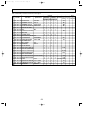
2. Cooling only type
PU-P1.6VGAA / YGAA.UK
PU-P2VGAA / YGAA.UK
PU-P2.5VGAA / YGAA.UK
PU-P1.6VGAA1 / YGAA1.UK PU-P2VGAA1 / YGAA1.UK
PU-P2.5VGAA1 / YGAA1.UK
Cooling
Cooling
Cooling
Function
Single, 50Hz, 220-230-240V / 3-ph, 50Hz, 380-400-415V(4wires)
Power supply (phase, cycle, voltage)
1.59
2.77
2.29
kW
Input
7.36 / 2.49
11.90 / 4.48
10.26 / 3.70
A
Running current
36 / 20
77 / 35
A
62 / 31
Starting current
Munsell 5Y 7/1
External finish
Linear Expansion Valve
Refrigerant control
Hermetic
Compressor
RE277VHSMT/RE277YFKM NE36VMJMT/NE36YEKMT NE41VMJMT/NE41YEKMT
Model
1.3
1.9
kW
1.6
Motor output
Line start
Starter type
Internal thermostat, HP switch, Discharge thermo / Thermal relay,Discharge thermo,HP switch
Protection devices
W
30
Crankcase heater
38
Plate fin coil
Heat exchanger
Propeller (direct) o 1
Fan
Fan(drive) o No.
kW
0.07
Fan motor output
K/min(CFM)
45(1,590)
50(1,770)
Airflow
55(1,940)
Defrost method
—
dB
Cooling
47
48
Noise level
mm(in.)
W
900(35-7/16)
mm(in.)
D
Dimensions
330+20(13+3/4)
mm(in.)
H
650(25-5/8)
855(33-5/8)
kg(lbs)
55(121)
82(181)
Weight
71(157)
Refrigerant
R407C
kg(lbs)
2.5(5.5)
3.1(6.8)
Charge
2.6(5.7)
L
0.57 (Ester)MEL56
1.2 (Ester)MEL56
Oil (Model)
mm(in.)
Pipe size O.D.
Liquid
9.52(3/8)
mm(in.)
Gas
15.88(5/8)
Indoor side
Connection method
Flared
Outdoor side
Flared
Max. 50m
Height difference
Between the indoor &
Max. 40m
Max. 50m
Piping length
outdoor unit
Max. 40m
REFRIGERANT PIPING
OUTDOOR UNIT
Service Ref.
Notes1. Rating Conditions (ISO T1)
Cooling : Indoor : D.B. 27˚C(80˚F), W.B. 19˚C (66˚F) Outdoor : D.B. 35˚C(95˚F), W.B. 24˚C (75˚F)
Refrigerant piping length (one way) : 5m (16ft)
2. Guaranteed operating range
Indoor
Upper limit D.B. 35˚C, W.B. 22.5˚C
Cooling
Lower limit D.B. 19˚C, W.B. 15˚C
Outdoor
D.B. 46˚C
D.B. -5˚C
3. Above data based on indicated voltage
Indoor Unit
1 phase 240V 50Hz
Outdoor Unit 1 phase 240V 50Hz / 3phase 415V 50Hz
12
OC261-B--1.qxp
03.2.19 3:07 PM
Page 13
OUTDOOR UNIT
Service Ref.
Function
Power supply (phase, cycle, voltage)
Input
Running current
Starting current
External finish
Refrigerant control
Compressor
Model
Motor output
Starter type
Protection devices
REFRIGERANT PIPING
Crankcase heater
Heat exchanger
Fan
Fan(drive) o No.
Fan motor output
Airflow
Defrost method
Noise level
Dimensions
Weight
Refrigerant
Charge
Oil (Model)
Pipe size O.D.
Connection method
Between the indoor &
outdoor unit
kW
A
A
kW
PU-P4VGAA / YGAA.UK
PU-P3VGAA / YGAA.UK
PU-P4VGAA1 / YGAA1.UK
PU-P3VGAA1 / YGAA1.UK
Cooling
Cooling
Single, 50Hz, 220-230-240V/3-ph, 50Hz, 380-400-415V(4wires)
3.43
3.27
15.71 / 5.55
14.81 / 5.29
99 / 49
93 / 47
Munsell 5Y 7/1
Linear Expansion Valve
Hermetic
NE56VNJMT / NE56YDKMT
NE52VNJMT / NE52YDKMT
2.7
2.5
Line start
Internal thermostat
HP switch
Discharge thermo
W
Thermal relay
HP switch
Discharge thermo
38
Plate fin coil
Propeller (direct) o 2
0.07+0.07
85(3,000)
Propeller (direct) o 1
0.07
50(1,770)
kW
K/min(CFM)
—
Cooling
W
D
H
dB
mm(in.)
mm(in.)
mm(in.)
kg(lbs)
51
49
900(35-7/16)
330+20(13+3/4)
1,260(49-5/8)
96(212)
855(33-5/8)
82(181)
R407C
kg(lbs)
L
mm(in.)
mm(in.)
4.0(8.8)
3.3(7.3)
1.3 (Ester)MEL56
9.52(3/8)
Liquid
Gas
Indoor side
Outdoor side
Height difference
Piping length
19.05(3/4)
15.88(5/8)
Flared
Flared
Max. 50m
Max. 50m
Notes1. Rating Conditions (ISO T1)
Cooling : Indoor : D.B. 27˚C(80˚F), W.B. 19˚C(66˚F) Outdoor : D.B. 35˚C(95˚F), W.B. 24˚C(75˚F)
Refrigerant piping length (one way) : 5m (16ft)
2. Guaranteed operating range
Indoor
Upper limit D.B. 35˚C , W.B. 22.5˚C
Cooling
Lower limit D.B. 19˚C, W.B. 15˚C
Outdoor
D.B. 46˚C
D.B. -5˚C
3. Above data based on indicated voltage
Indoor Unit
1 phase 240V 50Hz
Outdoor Unit 1 phase 240V 50Hz/3 phase 415V 50Hz
13
OC261-B--1.qxp
03.2.19 3:07 PM
Page 14
REFRIGERANT PIPING
OUTDOOR UNIT
Service Ref.
Function
Power supply (phase, cycle, voltage)
Input
Running current
Starting current
External finish
Refrigerant control
Compressor
Model
kW
A
A
kW
Motor output
Starter type
Protection devices
W
Crankcase heater
Heat exchanger
Fan
Fan(drive) o No.
kW
Fan motor output
K/min(CFM)
Airflow
Defrost method
Cooling
dB
Noise level
W
mm(in.)
Dimensions
D
mm(in.)
H
mm(in.)
kg(lbs)
Weight
Refrigerant
kg(lbs)
Charge
L
Oil (Model)
Liquid
mm(in.)
Pipe size O.D.
Gas
mm(in.)
Indoor side
Connection method
Outdoor side
Height difference
Between the indoor &
Piping length
outdoor unit
PU-P6YGAA.UK
PU-P5YGAA.UK
PU-P6YGAA1.UK
PU-P5YGAA1.UK
Cooling
Cooling
3-ph, 50Hz, 380-400-415V(4wires)
4.70
5.58
7.60
9.03
65.5
74
Munsell 5Y 7/1
Linear Expansion Valve
Hermetic
ZR61KCE-TFD-230 (YGAA.UK)
ZR72KCW-TFD-522
ZR61KCW-TFD-522 (YGAA1.UK)
4.2
3.5
Line start
Internal thermostat, thermal relay, HP switch, Discharge thermo
38
Plate fin coil
Propeller (direct) o 2
0.07+0.07
100(3,530)
95(3,360)
—
57
55
1,050(41-5/16)
330+20(13+3/4)
1,260(49-5/8)
122(269)
R407C
4.9(10.8)
4.6(10.1)
1.774 3MAW-POE
1.690 3MAW-POE
9.52(3/8)
19.05(3/4)
Flared
Flared
Max. 50m
Max. 50m
Notes1. Rating Conditions (ISO T1)
Cooling : Indoor : D.B. 27˚C(80˚F), W.B. 19˚C(66˚F) Outdoor : D.B. 35˚C(95˚F), W.B. 24˚C(75˚F)
Refrigerant piping length (one way) : 5m (16ft)
2. Guaranteed operating range
Indoor
Upper limit D.B. 35˚C , W.B.22.5˚C
Cooling
Lower limit D.B. 19˚C, W.B. 15˚C
Outdoor
D.B. 46˚C
D.B. -5˚C
3. Above data based on indicated voltage
Indoor Unit
1 phase 240V 50Hz
Outdoor Unit 3 phase 415V 50Hz
14
OC261-B--1.qxp
03.2.19 3:07 PM
6
Page 15
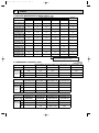
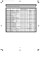
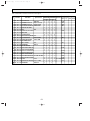
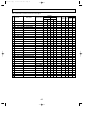
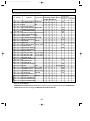
DATA
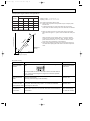
1. REFILLING REFRIGERANT CHARGE (R407C : kg)
Service Ref.
PUH-P1VGAA(1).UK
PUH-P1.6VGAA(1).UK
PU-P1.6VGAA(1).UK
PUH-P1.6YGAA(1).UK
PU-P1.6YGAA(1).UK
PUH-P2VGAA(1).UK
PU-P2VGAA(1).UK
PUH-P2YGAA(1).UK
PU-P2YGAA(1).UK
PUH-P2.5VGAA(1).UK
PU-P2.5VGAA(1).UK
PUH-P2.5YGAA(1).UK
PU-P2.5YGAA(1).UK
PUH-P3VGAA(1).UK
PU-P3VGAA(1).UK
PUH-P3YGAA(1).UK
PU-P3YGAA(1).UK
PUH-P4VGAA(1).UK
PU-P4VGAA(1).UK
PUH-P4YGAA(1).UK
PU-P4YGAA(1).UK
PUH-P5YGAA(1).UK
PU-P5YGAA(1).UK
PUH-P6YGAA(1).UK
PU-P6YGAA(1).UK
Piping length (one way)
30m
40m
50m
Factory
charged
—
—
1.7
2.6
3.0
—
2.5
2.5
2.6
3.0
—
2.5
2.5
2.6
3.1
3.7
—
2.6
2.5
2.6
3.1
3.7
—
2.6
2.9
3.1
3.3
3.9
4.5
3.1
2.9
3.1
3.3
3.9
4.5
3.1
2.9
3.1
3.3
3.9
4.5
3.3
2.9
3.1
3.3
3.9
4.5
3.3
3.4
3.7
4.0
4.7
5.4
4.0
3.4
3.7
4.0
4.7
5.4
4.0
4.0
4.3
4.6
5.3
6.0
4.6
4.3
4.6
4.9
5.6
6.3
4.9
10m
20m
1.6
1.7
1.8
2.4
2.5
2.4
This is a dividing line between the ones that
need no refrigerant charge and the ones that
need additional refrigerant charge.
(at 20°C)
[Except P5, P6]
PUH-P1.6VGAA(1).UK PUH-P1.6YGAA(1).UK PUH-P2VGAA(1).UK PUH-P2YGAA(1).UK
PUH-P1VGAA(1).UK PU-P1.6VGA(1).UK PU-P1.6YGA(1).UK
PU-P2VGAA(1).UK
PU-P2YGAA(1).UK
2. COMPRESSOR TECHNICAL DATA
Unit
Compressor model
RE189VHSMT
RE277VHSMT
RE277YFKM
NE36VMJMT
NE36YEKMT
U-V
Winding (R-C)
Resistance U-W
(S-C)
(")
W-V
2.79
1.80
10.8
0.89
5.01
3.36
3.00
10.8
2.03
5.01
—
—
10.8
—
5.01
Unit
Compressor model
U-V
(R-C)
Winding
U-W
Resistance (S-C)
(")
W-V
PUH-P2.5VGAA(1).UK PUH-P2.5YGAA(1).UK PUH-P3VGAA(1).UK PUH-P3YGAA(1).UK
PU-P3YGAA(1).UK
PU-P2.5VGAA(1).UK PU-P2.5YGAA(1).UK PU-P3VGAA(1).UK
NE41VMJMT
NE41NEKMT
NE52VNJMT
NE52YDKMT
0.87
5.00
0.64
3.59
2.22
5.00
1.67
3.59
—
5.00
—
3.59
(at 25°C)
(at 25°C)
PUH-P5YGAA(1).UK PUH-P6YGAA(1).UK
(1).UK PUH-P4YGAA(1).UK
PUH-P4VGAA
Unit
PU-P5YGAA(1).UK
PU-P6YGAA(1).UK
PU-P4VGAA(1).UK PU-P4YGAA(1).UK
ZR61KCE-TFD
Compressor model
NE56YDKMT
ZR72KCW-TFD
NE56VNJMT
ZR61KCW-TFD
U-V
3.32
0.628 ~ 0.722
0.517
0.62
(R-C)
Winding
U-W
3.32
0.628 ~ 0.722
0.517
1.59
Resistance (S-C)
(")
W-V
3.32
0.628 ~ 0.722
0.517
—
15
OC261-B--1.qxp
03.2.19 3:07 PM
Page 16
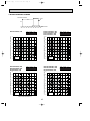
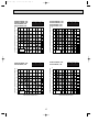
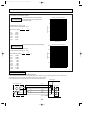
3. NOISE CRITERION CURVES
MICROPHONE
1m
UNIT
1m
GROUND
MODE SPL(dB)
COOLING
46
HEATING
48
PUH-P1.6VGAA(1).UK
PUH-P1.6YGAA(1).UK
PU-P1.6VGAA(1).UK
PU-P1.6YGAA(1).UK
LINE
90
OCTAVE BAND SOUND PRESSURE LEVEL, dB re 0.0002 MICRO BAR
OCTAVE BAND SOUND PRESSURE LEVEL, dB re 0.0002 MICRO BAR
PUH-P1VGAA(1).UK
80
70
NC-70
60
NC-60
50
NC-50
40
NC-40
30
NC-30
20
10
APPROXIMATE
THRESHOLD OF
HEARING FOR
CONTINUOUS
NOISE
63
125
NC-20
250
500
1000
2000
4000
8000
80
70
NC-70
60
NC-60
50
NC-50
40
NC-40
30
NC-30
20
10
APPROXIMATE
THRESHOLD OF
HEARING FOR
CONTINUOUS
NOISE
63
80
NC-70
60
NC-60
50
NC-50
40
NC-40
30
NC-30
20
10
APPROXIMATE
THRESHOLD OF
HEARING FOR
CONTINUOUS
NOISE
63
125
NC-20
250
500
1000
2000
4000
250
500
PUH-P2.5VGAA(1).UK
PUH-P2.5YGAA(1).UK
PU-P2.5VGAA(1).UK
PU-P2.5YGAA(1).UK
LINE
90
70
125
NC-20
1000
2000
4000
8000
BAND CENTER FREQUENCIES, Hz
OCTAVE BAND SOUND PRESSURE LEVEL, dB re 0.0002 MICRO BAR
OCTAVE BAND SOUND PRESSURE LEVEL, dB re 0.0002 MICRO BAR
MODE SPL(dB)
COOLING
48
HEATING
49
LINE
90
BAND CENTER FREQUENCIES, Hz
PUH-P2VGAA(1).UK
PUH-P2YGAA(1).UK
PU-P2VGAA(1).UK
PU-P2YGAA(1).UK
MODE SPL(dB)
COOLING
47
HEATING
49
8000
MODE SPL(dB)
COOLING
48
HEATING
50
90
80
70
NC-70
60
NC-60
50
NC-50
40
NC-40
30
NC-30
20
10
APPROXIMATE
THRESHOLD OF
HEARING FOR
CONTINUOUS
NOISE
63
125
NC-20
250
500
1000
2000
4000
BAND CENTER FREQUENCIES, Hz
BAND CENTER FREQUENCIES, Hz
16
LINE
8000
03.2.19 3:07 PM
Page 17
OCTAVE BAND SOUND PRESSURE LEVEL, dB re 0.0002 MICRO BAR
PUH-P3VGAA(1).UK
PUH-P3YGAA(1).UK
PU-P3VGAA(1).UK
PU-P3YGAA(1).UK
MODE SPL(dB)
COOLING
49
HEATING
51
PUH-P4VGAA(1).UK
PUH-P4YGAA(1).UK
PU-P4VGAA(1).UK
PU-P4YGAA(1).UK
LINE
90
OCTAVE BAND SOUND PRESSURE LEVEL, dB re 0.0002 MICRO BAR
OC261-B--1.qxp
80
70
NC-70
60
NC-60
50
NC-50
40
NC-40
30
NC-30
20
10
APPROXIMATE
THRESHOLD OF
HEARING FOR
CONTINUOUS
NOISE
63
125
NC-20
250
500
1000
2000
4000
8000
80
70
NC-70
60
NC-60
50
NC-50
40
NC-40
30
NC-30
20
10
APPROXIMATE
THRESHOLD OF
HEARING FOR
CONTINUOUS
NOISE
63
80
NC-70
60
NC-60
50
NC-50
40
NC-40
30
NC-30
20
10
APPROXIMATE
THRESHOLD OF
HEARING FOR
CONTINUOUS
NOISE
63
125
NC-20
250
500
1000
2000
4000
250
500
PUH-P6YGAA(1).UK
PU-P6YGAA(1).UK
LINE
90
70
125
NC-20
1000
2000
4000
8000
BAND CENTER FREQUENCIES, Hz
OCTAVE BAND SOUND PRESSURE LEVEL, dB re 0.0002 MICRO BAR
OCTAVE BAND SOUND PRESSURE LEVEL, dB re 0.0002 MICRO BAR
MODE SPL(dB)
COOLING
55
HEATING
56
LINE
90
BAND CENTER FREQUENCIES, Hz
PUH-P5YGAA(1).UK
PU-P5YGAA(1).UK
MODE SPL(dB)
COOLING
51
HEATING
53
8000
MODE SPL(dB)
COOLING
57
HEATING
58
90
80
70
NC-70
60
NC-60
50
NC-50
40
NC-40
30
NC-30
20
10
APPROXIMATE
THRESHOLD OF
HEARING FOR
CONTINUOUS
NOISE
63
125
NC-20
250
500
1000
2000
4000
BAND CENTER FREQUENCIES, Hz
BAND CENTER FREQUENCIES, Hz
17
LINE
8000
er
Ov
mm
10
m
0m
50
F
R
E
E
Ov
3
w1
2
2
1
1
.
.
.
.
.
.
er
10
mm
er
Ov
m
0m
10
2
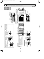
SERVICE SPACE
Over10
Over500
Service Space
Front Piping Hole
(Knock-Out)
92
65
2
[9
40
< Front Side >
Power Supply Wiring Hole
(2-[27Knock-Out)
50
100
50
Right Piping Hole
(Knock-Out)
< Right Side >
Power Supply Wiring Hole
(2-[27Knock-Out)
These holes are provided for cases where the unit must
be secured by the base AND by the top surface.
Use Self Tapping screws 5 x L15 or less.(Obtained locally)
Piping Knock-Out Hole Details
3
FOUNDATION BOLTS
[9
2
92
65
40
220
220
Rear Piping Hole
(Knock-Out)
Rear Trunking Hole
(Knock-Out)
< Rear Side >
Power Supply Wiring Hole
(2-[27Knock-Out)
30
230
3
FOUNDATION
<Foundation bolt height>
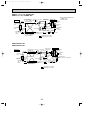
Dimensions of space needed Please secure the unit firmly
for service access are
with 4 foundation (M10) bolts.
shown in the below diagram. (Bolts and washers must be
purchased locally).
Over100
Over500
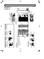
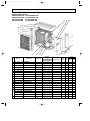
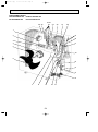
. Refrigerant GAS pipe connection (FLARE)P1.6V(Y)GAA: [15.88 (5/8F)
. Refrigerant GAS pipe connection (FLARE)P1VGAA
: [12.7 (1/2F)
. Refrigerant LIQUID pipe connection (FLARE)P1.6V(Y)GAA: [9.52 (3/8F)
. Refrigerant LIQUID pipe connection (FLARE)P1VGAA
: [6.35 (1/4F)
. Height of STOP VALVE connection location.
. 3-[3.6 holes (for securing the top of the unit)
Explanation of Notes
er
Front Trunking Hole
(Knock-Out)
Ov
55
22
4
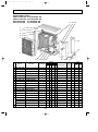
PIPING-WIRING DIRECTIONS
30
230
Rear
Air
Intake
Side
Air
Intake
Piping and wiring connections
can be made from 4 directions:
Front, Right, Rear and Below.
Side Air
Intake
30
Handle for
moving
109
2-12x40 oval holes
(Foundation Bolt M10)
500
155
155
900
155
Installation Feet
Air Discharge
318
200
Rear Air Intake
R
S
T
1
2
3
51
Handle for moving
Right..Indoor/Outdoor Wiring
Left...Power supply Wiring
Terminal Connections
18
Bottom Piping Hole
(Knock-Out)
Front Piping Cover
Rear Piping Cover
2
1
Earth Point
Service Panel
43
Drain Hole
(5-[33holes)
70
200
2-U Shaped notched holes
(Foundation Bolt M10)
58
FREE SPACE (Around the Unit)
33 27 100
(14)
370
The diagram below shows a
basic example.
Explanation of particular details are
given in the installation manuals etc.
68 63
33
68 63
33
412
1
55 40
Less than
30mm
650
637
55
22
330
20
215
29
55
53
28
18
70
18
85
PUH-P1VGAA(1).UK
PUH-P1.6VGAA(1).UK
PUH-P1.6YGAA(1).UK
PU-P1.6VGAA(1).UK
PU-P1.6YGAA(1).UK
424
7
03.2.19 3:07 PM
w1 196
w1 248
OC261-B--1.qxp
Page 18
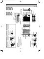
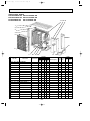
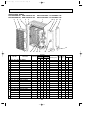
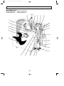
OUTLINES AND DIMENSIONS
Unit : mm
er
Ov
mm
10
5
m
m
00
F
R
E
E
Ov
er
10
mm
e
Ov
0
r1
m
0m
SERVICE SPACE
Over10
Service Space
Over500
Front Piping Hole
(Knock-Out)
Front Trunking Hole
(Knock-Out)
92
65
2
[9
40
< Front Side >
Power Supply Wiring Hole
(2-[27Knock-Out)
55
22
50
100
50
Right Piping Hole
(Knock-Out)
< Right Side >
Power Supply Wiring Hole
(2-[27Knock-Out)
Handle
These holes are provided for cases where the unit must
be secured by the base AND by the top surface together.
Use Self Tapping screws 5 x L15 or less.
(Obtained Locally)
Piping Knock-Out Hole Details
2
1
. . . Refrigerant GAS pipe connection (FLARE) [15.88 (5/8F)
. . . Refrigerant LIQUID pipe connection (FLARE) [9.52 (3/8F)
w1 . . . Height of STOP VALVE connection location.
3 . . . 3-[3.6 holes (for securing the top of the unit)
Explanation of Notes
er
Ov
2
3
FOUNDATION BOLTS
92
65
2
[9
40
220
220
Rear Piping Hole
(Knock-Out)
Rear Trunking Hole
(Knock-Out)
< Rear Side >
Power Supply Wiring Hole
(2-[27Knock-Out)
30
230
3
FOUNDATION
<Foundation bolt height>
30
230
Dimensions of space needed Please secure the unit firmly
for service access are
with 4 foundation (M10) bolts.
shown in the below diagram. (Bolts and washers must be
purchased locally).
Over100
FREE SPACE (Around the Unit)
68 63
33
100
27
33
4
Rear
Air
Intake
Side
Air
Intake
Side Air
Intake
Handle
30
2-12x40 oval holes
(Foundation Bolt M10)
PIPING-WIRING DIRECTIONS
Piping and wiring connections
can be made from 4 directions:
Front, Right, Rear and Below.
109
500
155
155
900
155
Installation Feet
Air Discharge
318
200
Rear Air Intake
R
S
T
1
2
3
51
18
43
Bottom Piping Hole
(Knock-Out)
Front Piping Cover
Rear Piping Cover
2
1
Earth Point
Handle
Service Panel
Right..Indoor/Outdoor Wiring
Left...Power supply Wiring
Terminal Connections
Drain Hole
(5-[33holes)
70
200
2-U Shaped notched holes
(Foundation Bolt M10)
58
The diagram below shows a
basic example.
Explanation of particular details are
given in the installation manuals etc.
68 63
330
(14)
370
1
55 40
840
55
22
412
Over500
855
Less than
30mm
33
18
20
442
215
29
55
53
28
70
19
85
PUH-P2VGAA(1).UK
PUH-P2YGAA(1).UK
PUH-P2.5VGAA(1).UK
PUH-P2.5YGAA(1).UK
PUH-P3VGAA(1).UK
PUH-P3YGAA(1).UK
PU-P2VGAA(1).UK
PU-P2YGAA(1).UK
PU-P2.5VGAA(1).UK
PU-P2.5YGAA(1).UK
PU-P3VGAA(1).UK
PU-P3YGAA(1).UK
627
03.2.19 3:07 PM
w1 376
w1 428
OC261-B--1.qxp
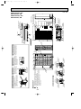
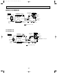
Page 19
Unit : mm
FREE SPACE (Around the Unit)
10
Ov
mm
er
0
50
mm
F
R
E
E
Ov
mm
m
0m
2
SERVICE SPACE
Over10
Service Space
Over500
Dimensions of space needed
for service access are
shown in the below diagram.
Front Piping Hole
(Knock-Out)
Front Trunking Hole
(Knock-Out)
92
65
2
[9
40
33
68 63
< Front Side >
Power Supply Wiring Hole
(2-[27Knock-Out)
55
22
50
50
100
Right Piping Hole
(Knock-Out)
< Right Side >
Power Supply Wiring Hole
(2-[27Knock-Out)
Handle
These holes are provided for cases where the unit must
be secured by the base AND by the top surface together.
Use Self Tapping screws 5 x L15 or less.
(Obtained Locally)
. Refrigerant GAS pipe connection(FLARE) [19.05 (3/4F)
. Refrigerant LIQUID pipe connection(FLARE) [9.52 (3/8F) 3
. Height of STOP VALVE connection location.
. 3-[3.6 holes (for securing the top of the unit)
10
10
Piping Knock-Out Hole Details
.
.
.
.
er
O
r
ve
33 27 100
1
2
.
.
.
w1
3 .
Explanation of Notes
er
Ov
The diagram below shows a
basic example.
Explanation of particular details are
given in the installation manuals etc.
3
FOUNDATION BOLTS
92
2
[9
65
40
220
220
Rear Piping Hole
(Knock-Out)
Rear Trunking Hole
(Knock-Out)
< Rear Side >
Power Supply Wiring Hole
(2-[27Knock-Out)
30
230
FOUNDATION
<Foundation bolt height>
230
30
Please secure the unit firmly
with 4 foundation (M10) bolts.
(Bolts and washers must be
purchased locally).
4
PIPING-WIRING DIRECTIONS
Rear
Air
Intake
Side
Air
Intake
Piping and wiring connections
can be made from 4 directions:
Front, Right, Rear and Below.
Side Air
Intake
Handle
2-12x40 oval holes
(Foundation Bolt M10)
30
109
500
155
155
900
155
Installation Feet
Air Discharge
318
200
Rear Air Intake
51
18
43
Right..Indoor/Outdoor Wiring
Left...Power supply Wiring
Terminal Connections
Front Piping Cover
Rear Piping Cover
Bottom Piping Hole
(Knock-Out)
2
1
Handle
Earth Point
Service Panel
Drain Hole
(5-[33Holes)
70
200
2-U Shaped notched holes
(Foundation Bolt M10)
58
1
55 40
1246
55
412
Over100
Over500
1260
68 63
33
33
Less than
30mm
22
330
20
598
352
215
85
(14)
370
28
29
50
53
18
70
20
W1 376
PUH-P4VGAA(1).UK
PUH-P4YGAA(1).UK
PU-P4VGAA(1).UK
PU-P4YGAA(1).UK
1033
03.2.19 3:07 PM
W1 428
OC261-B--1.qxp
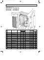
Page 20
Unit : mm
10
Ov
mm
er
m
0m
50
Ov
er
10
mm
00
r1
e
Ov
mm
SERVICE SPACE
Over10
Front Piping Hole
(Knock-Out)
92
65
2
[9
40
< Front Side >
Power Supply Wiring Hole
(2-[27Knock-Out)
Piping Knock-Out Hole Details
50
100
50
Right Piping Hole
(Knock-Out)
< Right Side >
Power Supply Wiring Hole
(2-[27Knock-Out)
Handle
These holes are provided for cases where the unit must
be secured by the base AND by the top surface together.
Use Self Tapping screws 5 x L15 or less.
(Obtained Locally)
Front Trunking Hole
(Knock-Out)
1
3
3
FOUNDATION BOLTS
230
5
295
2
[9
92
65
40
Rear Piping Hole
(Knock-Out)
Rear Trunking Hole
(Knock-Out)
295
FOUNDATION
<Foundation bolt height>
< Rear Side >
Power Supply Wiring Hole
(2-[27Knock-Out)
Service Space
Over500
. . . Refrigerant GAS pipe connection(FLARE) [19.05 (3/4F)
2 . . . Refrigerant LIQUID pipe connection(FLARE) [9.52 (3/8F)
w1 . . . Height of STOP VALVE connection location.
3 . . . 3-[3.6 holes (for securing the top of the unit)
Explanation of Notes
er
Ov
2
1260
1246
F
R
E
E
55
22
Over100
Over500
Dimensions of space needed Please secure the unit firmly
for service access are
with 4 foundation (M10) bolts.
shown in the below diagram. (Bolts and washers must be
purchased locally).
55
FREE SPACE (Around the Unit)
68 63
33
100
27
33
68 63
33
The diagram below shows a
basic example.
Explanation of particular details are
given in the installation manuals etc.
5
230
Rear
Air
Intake
Side
Air
Intake
Side Air
Intake
330
Handle
30
109
2-12x40 oval holes
(Foundation Bolt M10)
PIPING-WIRING DIRECTIONS
Piping and wiring connections
can be made from 4 directions:
Front, Right, Rear and Below.
4
172
398
148
148
1050
Air Discharge
148
Installation Feet
600
Rear Air Intake
53
Right..Indoor/Outdoor Wiring
Left...Power supply Wiring
Terminal Connections
18
Bottom Piping Hole
(Knock-Out)
Front Piping Cover
Rear Piping Cover
2
1
Handle
Earth Point
Service Panel
44
Drain Hole
(5-[33Holes)
90
225
2-U Shaped notched holes
(Foundation Bolt M10)
58
1
55 40
Less than
30mm
22
(14)
370
w1 422
20
598
352
215
85
29
50
53
18
21
70
PUH-P5YGAA(1).UK
PU-P5YGAA(1).UK
PUH-P6YGAA(1).UK
PU-P6YGAA(1).UK
1033
03.2.19 3:07 PM
w1 478
OC261-B--1.qxp
Page 21
Unit : mm
OC261-B--1.qxp
8
03.2.19 3:08 PM
Page 22
WIRING DIAGRAM
PUH-P1, 1.6, 2, 2.5, 3, 4VGAA.UK
PUH-P1, 1.6, 2, 2.5, 3, 4VGAA1.UK
22
OC261-B--1.qxp
03.2.19 3:08 PM
Page 23
PUH-P1.6, 2, 2.5, 3, 4, 5, 6YGAA.UK
PUH-P1.6, 2, 2.5, 3, 4, 5, 6YGAA1.UK
23
OC261-B--1.qxp
03.2.19 3:08 PM
Page 24
PU-P1.6, 2, 2.5, 3, 4VGAA.UK
PU-P1.6, 2, 2.5, 3, 4VGAA1.UK
24
OC261-B--1.qxp
03.2.19 3:08 PM
Page 25
PU-P1.6, 2, 2.5, 3, 4, 5, 6YGAA.UK
PU-P1.6, 2, 2.5, 3, 4, 5, 6YGAA1.UK
25
OC261-B--1.qxp
9
03.2.19 3:08 PM
Page 26
WIRING SPECIFICATIONS
WIRING SPECIFICATIONS FOR 220~240V 50Hz
(INDOOR-OUTDOOR CONNECTING CABLE)
Cross section
of cable
PU(H)-P1VGAA(1).UK~P6YGAA(1).UK
(Except PUH-8YE,PUH-10YE)
Wire size
(mm2)
Number
of wires
Polarity
L(m)
✽6
2.5
3
Clockwise : S1-S2-S3
w Pay attention to stripe of yellow and green
(50)
✽2
2.5
3
Not applicable
(Because center wire has no cover finish)
1.5
4
From left to right : S1-Open-S2-S3
(45)
✽3
2.5
4
Clockwise : S1-S2-S3-Open
w Connect S1 and S3 to the opposite angle
60
✽4
Round
Flat
Not
applicable
✽5
Flat
Round
✽1 : Power supply cords of appliances shall not be lighter than design 245 IEC or 227 IEC.
✽2 : In case that cable with stripe of yellow and green is available.
✽3 : In case of regular polarity connection (S1-S2-S3), wire size is 1.5mm2.
✽4 : In case of regular polarity connection (S1-S2-S3).
✽5 : In the flat cables are connected as this picture, they can be used up to 80m.
(3C Flat cable ✕ 2)
S1 S2 S3
✽6 : Mentioned cable length is just a reference value.
It may be different depending on the condition of installation, Humidity or materials, etc.
26
OC261-B--1.qxp
03.2.19 3:08 PM
10
Page 27
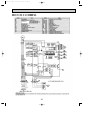
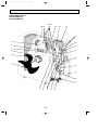
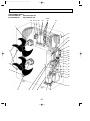
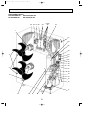
REFRIGERANT SYSTEM DIAGRAM
PUH-P1, 1.6, 2, 2.5, 3VGAA.UK
PUH-P1.6, 2, 2.5, 3YGAA.UK
Refrigerant pipe
Ball valve
P1···12.7A({1/2")
4-way valve
P1.6~P3···15.88A({5/8") (#50)
(with heat insulator)
Strainer
Indoor unit
Thermistor
(TH1)
Thermistor
(TH5)
High pressure
protect switch
Thermistor
(TH6)
Flexible tube
Service
port
Service
port
Strainer
Indoor coil
thermistor
(TH2)
Distributor
with
strainer
Outdoor unit
Outdoor heat exchanger
<4-way valve solenoid coil>
Heating : ON
Cooling : OFF
Flared
connection
Thermistor
(TH3)
Muffler
Accumulator
(#50)
Strainer
Distributor
with
strainer
Thermistor(TH4)
Compressor (#100)
Strainer
Drier
Refrigerant pipe
Stop valve
P1···6.35A({1/4")
(with service port)
P1.6~P3···9.52A({3/8")
(with heat insulator)
(#100)
Strainer
Linear expansion valve
Refrigerant flow in cooling
Refrigerant flow in heating
PUH-P4VGAA.UK
PUH-P4YGAA.UK
Indoor unit
Thermistor
(TH1)
Thermistor
(TH5)
High pressure
protect switch
Refrigerant pipe Ball valve 4-way valve
19.05A({3/4")
(#50)
(with heat insulator) Strainer
Flexible tube
Strainer Flared
connection
Accumulator
Indoor coil
thermistor
(#50)
(TH2)
Strainer Drier
Distributor
with
strainer
Thermistor
(TH6)
Distributor
with
strainer
Service
port
Muffler
Service
port
Outdoor unit
Thermistor
(TH4)
Thermistor
(TH3)
Compressor (#100)
(#100)
Strainer
Strainer
Refrigerant pipe Stop valve
(with service port)
9.52A({3/8")
(with heat insulator)
Capillary tube
(O.D.4.0✕I.D.3.0-L350)✕2pcs
Liner expansion valve
Refrigerant flow in cooling
Refrigerant flow in heating
PUH-P5YGAA.UK
PUH-P5YGAA1.UK
PUH-P6YGAA.UK
PUH-P6YGAA1.UK
High pressure
protect switch Outdoor unit
Ball valve
Indoor unit
Thermistor
(TH1)
Thermistor
(TH5)
Distributor
with
strainer
Refrigerant pipe
19.05A({3/4")
(with heat insulator)
4-way valve
Service
port
(#50)
Strainer
Thermistor
(TH6)
Distributor
with
strainer
Flexible tube
Service
port
Capillary
Strainer Flared tube w1
connection
Bypass
valve
Thermistor
(TH2)
Muffler
Thermistor
(TH4)
Thermistor
(TH3)
Accumulator
Compressor
Drier
Strainer
Refrigerant pipe
(#50)
9.52A({3/8")
(with heat insulator)
Stop valve
(with service port)
27
Strainer
(#100)
Strainer
(#100)
Liner expansion valve
Capillary tube
(O.D.4.0✕I.D.3.0-L200)✕2pcs
w1 : O.D.4.0✕I.D.2.0-L400(PUH-P5YGAA(1).UK)
O.D.4.0✕I.D.3.0-L450(PUH-P6YGAA(1).UK)
Refrigerant flow in cooling
Refrigerant flow in heating
OC261-B--1.qxp
03.2.19 3:08 PM
Page 28
PU-P1.6, 2, 2.5, 3VGAA.UK
PU-P1.6, 2, 2.5, 3YGAA.UK
High pressure
protect switch
Refrigerant pipe Ball valve
15.88A({5/8")
(#50)
(with heat insulator) Strainer
Indoor unit
Thermistor
(TH1)
Outdoor unit
Outdoor heat exchanger
Thermistor
(TH6)
Flexible tube
Service
port
Flared
connection
Strainer
Thermistor
(TH5)
Thermistor
(TH3)
Thermistor(TH4)
Accumulator
(#50)
Strainer Drier
Indoor coil
thermistor
(TH2)
Distributor
with
strainer
Service
port
Compressor (#100)
Strainer
Refrigerant pipe Stop valve
9.52A({3/8")
(with service port)
(with heat insulator)
(#100)
Strainer
Distributor
with
strainer
Linear expansion valve
Refrigerant flow in cooling
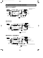
PU-P4VGAA.UK
PU-P4YGAA.UK
High pressure
protect switch
Refrigerant pipe Ball valve
19.05A({3/4")
(#50)
(with heat insulator)
Strainer
Indoor unit
Thermistor
(TH1)
Flexible tube
Thermistor
(TH5)
Distributor
with
strainer
Thermistor
(TH6)
Distributor
with
strainer
Service
port
Service
port
Thermistor
(TH4)
Strainer Flared
connection
Indoor coil
thermistor
(TH2)
Outdoor unit
Accumulator
(#50)
Strainer Drier
Compressor
Refrigerant pipe Stop valve
(with service port)
9.52A({3/8")
(with heat insulator)
Thermistor
(TH3)
(#100)
Strainer
Capillary tube
(O.D.4.0✕I.D.3.0-L350)✕2pcs
(#100)
Strainer
Liner expansion valve
Refrigerant flow in cooling
PU-P5YGAA.UK
PU-P5YGAA1.UK
Indoor unit
PU-P6YGAA.UK
PU-P6YGAA1.UK
Thermistor
(TH1)
Thermistor
(TH5)
Thermistor
(TH6)
Flexible tube
Service
port
Service
port
Strainer Flared
connection
Accumulator
(#50)
Strainer
Thermistor
(TH2)
Distributor
with
strainer
High pressure Outdoor unit
protect switch
Ball valve
Refrigerant pipe
19.05A({3/4")
(#50)
(with heat insulator)
Strainer
Refrigerant pipe
9.52A({3/8")
(with heat insulator)
Drier
Thermistor
(TH4)
Thermistor
(TH3)
Compressor
Strainer
(#100)
Stop valve
(with service port)
Strainer
(#100)
Liner expansion valve
Refrigerant flow in cooling
28
Distributor
with
strainer
Capillary tube
(O.D.4.0✕I.D.3.0-L200)✕2pcs
OC261-B--1.qxp
03.2.19 3:08 PM
Page 29
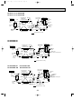
PUH-P1, 1.6, 2, 2.5, 3VGAA1.UK
PUH-P1.6, 2, 2.5, 3YGAA1.UK
Refrigerant pipe
Ball valve
P1···12.7A({1/2")
4-way valve
P1.6~P3···15.88A({5/8") (#50)
(with heat insulator)
Strainer
Indoor unit
Thermistor
(TH1)
Thermistor
(TH5)
High pressure
protect switch
Thermistor
(TH6)
Flexible tube
Service
port
Service
port
Strainer
Indoor coil
thermistor
(TH2)
Distributor
with
strainer
Outdoor unit
Outdoor heat exchanger
<4-way valve solenoid coil>
Heating : ON
Cooling : OFF
Flared
connection
Thermistor
(TH3)
Muffler
Thermistor(TH4)
Accumulator
Compressor (#100)
Strainer
Refrigerant pipe
Stop valve
P1···6.35A({1/4")
(with service port)
P1.6~P3···9.52A({3/8")
(with heat insulator)
(#100)
Strainer
Distributor
with
strainer
Linear expansion valve
Refrigerant flow in cooling
Refrigerant flow in heating
PUH-P4VGAA1.UK
PUH-P4YGAA1.UK
Indoor unit
Thermistor
(TH1)
Thermistor
(TH5)
Distributor
with
strainer
Refrigerant pipe Ball valve 4-way valve
19.05A({3/4")
(#50)
(with heat insulator)
Strainer
Flexible tube
Service
port
Muffler
High pressure
protect switch
Outdoor unit
Thermistor
(TH6)
Distributor
with
strainer
Service
port
Thermistor
(TH4)
Strainer Flared
connection
Indoor coil
Accumulator
thermistor
(TH2)
Thermistor
(TH3)
Compressor (#100)
Strainer
Stop valve
Refrigerant pipe
(with service port)
9.52A({3/8")
(with heat insulator)
(#100)
Strainer
Liner expansion valve
Refrigerant flow in cooling
Refrigerant flow in heating
29
Capillary tube
(O.D.4.0✕I.D.3.0-L350)✕2pcs
OC261-B--1.qxp
03.2.19 3:08 PM
Page 30
PU-P1.6, 2, 2.5, 3VGAA1.UK
PU-P1.6, 2, 2.5, 3YGAA1.UK
High pressure
protect switch
Refrigerant pipe Ball valve
15.88A({5/8")
(#50)
(with heat insulator)
Strainer
Indoor unit
Thermistor
(TH1)
Outdoor unit
Outdoor heat exchanger
Thermistor
(TH6)
Flexible tube
Service
port
Flared
connection
Strainer
Thermistor
(TH5)
Thermistor(TH4)
Accumulator
Indoor coil
thermistor
(TH2)
Distributor
with
strainer
Thermistor
(TH3)
Service
port
Compressor
Refrigerant pipe Stop valve
9.52A({3/8")
(with service port)
(with heat insulator)
(#100)
Strainer
(#100)
Strainer
Distributor
with
strainer
Linear expansion valve
Refrigerant flow in cooling
PU-P4VGAA1.UK
PU-P4YGAA1.UK
Indoor unit
Refrigerant pipe
Ball valve
19.05A({3/4")
(#50)
(with heat insulator)
Strainer
High pressure
protect switch
Flexible tube
Thermistor
(TH1)
Service
port
Thermistor
(TH4)
Service
port
Strainer Flared
connection
Thermistor
(TH5)
Distributor
with
strainer
Indoor coil
thermistor
(TH2)
Accumulator
Compressor (#100)
Strainer
Stop valve
Refrigerant pipe
(with service port)
9.52A({3/8")
(with heat insulator)
Outdoor unit
Thermistor
(TH6)
Distributor
with
strainer
Thermistor
(TH3)
(#100)
Strainer
Liner expansion valve
Refrigerant flow in cooling
30
Capillary tube
(O.D.4.0✕I.D.3.0-R350)✕2pcs
OC261-B--2.qxp
11
03.2.19 3:12 PM
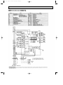
Page 31
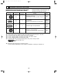
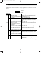
TROUBLESHOOTING
1. SELF-DIAGNOSTIC FUNCTION
• The blinking patterns of two LEDs—LED1(Green) and LED2(Red)—show the diagnoses of troubles in case of malfunction.
• By 7SEG indicator board indicates the operation mode and inspection types. For the details, refer to “OCT03 REVISED
EDITION-C”.
LED1 (Green)
LED2 (Red)
Indication (O.B)
Error Name
Inspection method
LED1 LED2
(Green) (Red)
1 Check if the wires of power supply are connected to their
1 blink 1 blink •Negative Phase detection
corresponding terminals on TB1.
•The wires of power supply and connecting
wires of indoor / outdoor units are crossed 2 Check if the wirings are correct on power supply (TB1) and
outdoor power supply board (TB2).
with one another.
2 blinks •51CM connector open
1 Check if the connectors of 51CM (51C) on
outdoor controller board are disconnected.
2 Check the continuity of connector 51CM (51C) by using a
tester.
1 blink •Indoor / outdoor unit connector mis-wiring 1 Check if the wirings are correct on the connecting wires of
•Excessive numbers of indoor units per an
indoor / outdoor units.
outdoor unit (five or more)
2 blinks
2 Check if a single outdoor unit connects five or more indoor
•Mis-wiring of indoor / outdoor unit connection
units.
wires (crossed wiring or disconnection)
•Start-up time is up
2 blinks •Indoor / outdoor unit transmission error
1 Check if the wirings are correct on the connecting wires of
(Signal receiving error: Indoor controller side)
indoor / outdoor units.
•Indoor / outdoor unit transmission error
2 Check if there is noise on the wires of power supply and
(Transmitting error: Indoor controller side)
connecting wires of indoor / outdoor units.
•Indoor / outdoor unit transmission error
3 Check if there is noise on both indoor and outdoor
(Signal receiving error :Outdoor controller side)
controller board.
•Indoor / outdoor unit transmission error
4 Turn the power off and let the units operate again to confirm.
(Transmitting error: Outdoor controller side)
3 blinks •Remote controller transmission error
1 Check if the wirings are correct on indoor units or remote
(Signal receiving error: Remote controller side)
controllers.
•Remote controller transmission error
2 Check if there is noise on the transmission lines of remote
(Transmitting error: Remote controller side)
controllers.
•Remote controller transmission error
3 Turn the power off and let the units operate again to confirm.
(Signal receiving error: Indoor controller side)
•Remote controller transmission error
(Transmitting error: Indoor controller side)
4 blinks •Undefined error code
1 Check if there is noise on the transmission lines of remote
controllers.
2 Check if there is noise on the connecting wires of
indoor/outdoor units.
3 Turn the power off and let the units operate again to confirm.
To be continued on the next page.
31
OC261-B--2.qxp
03.2.19 3:12 PM
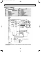
Page 32
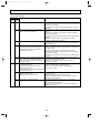
From the preceding page.
Indication (O.B)
Error Name
Inspection method
LED1 LED2
(Green) (Red)
3 blinks 1 blink •Abnormal high discharge temperature(TH4) 1 Check if ball valves are open.
2 Check the continuity of connector (TH4) on outdoor controller
board by using a tester.
3 Check if the unit fills the refrigerant at the same amount as
specified.
1 Check if indoor / outdoor units have a short cycle on their air
2 blinks •Abnormal high pressure (High-pressure
ducts.
switch 63H has been tripped)
2 Check if the connector of 52C (63H) on outdoor controller
board is disconnected.
3 Check if the units get their heat exchanger and filter dirty and
clogged.
4 Measure resistance values among terminals on linear
expansion valve by using a tester.
3 blinks •Protection from overheat operation (TH3) 1 Check if outdoor unit has a short cycle on its air duct.
2 Check if the connector of TH3 on outdoor controller board is
disconnected.
1 Check if ball valves are open.
4 blinks •Compressor's overcurrent (Overload)
2 Measure resistance values among terminals on compressor
•Thermal relay (51C) has been tripped
by using a tester.
•Overcurrent has locked the operation of
3
Check if outdoor unit has a short cycle on its air duct.
compressor in start-up.
4 Check if the connector of 51CM (51C) on outdoor controller
board is disconnected.
5 Check if the units get their heat exchanger and filter dirty and
clogged.
5 blinks •Open / short circuit of discharge thermistor (TH4) 1 Check if the connectors of TH4, TH3, and TH6 on outdoor
•Open / short circuit of liquid pipe thermistor (TH3)
controller board are disconnected.
•Open / short circuit of EVA / COND pipe
2 Measure the resistance values of each thermistor
thermistor (TH5)
(TH4, TH3, and TH6).
4 blinks 1 blinks •Abnormality of room temperature thermistor 1 Check if the connectors of CN20, CN21, and CN29 on
outdoor controller board are disconnected.
(Indoor unit side: TH1)
2 Measure the resistance values of each thermistor
•Abnormality of Liquid pipe thermistor
(TH1, TH2, and TH5).
(Indoor unit side:TH2)
•Abnormality of EVA / COND pipe thermistor
(Indoor unit side: TH5)
1 Check if the connector of CN31 on outdoor controller board
2 blinks •Abnormality of drain sensor
is disconnected.
(Indoor unit side : (DS))
•Malfunction of drain-up machine
2 Measure the resistance value of drain sensor.
3 Measure resistance values among terminals on drain-up
machine by using a tester.
1 Check if the connectors of CN20, CN21, and CN29 on
3 blinks •Abnormality of pipe temperature
outdoor controller board are disconnected.
2 Check if ball valves are open.
3 Check if the wirings are correct on the connecting wires of
indoor / outdoor units.
32
OC261-B--2.qxp
03.2.19 3:12 PM
Page 33
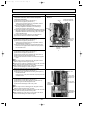
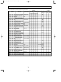
2. HOW TO CHECK THE PARTS
PUH-P1, 1.6, 2, 2.5, 3, 4VGAA(1).UK
PU-P1.6, 2, 2.5, 3, 4VGAA(1).UK
PUH-P1.6, 2, 2.5, 3, 4, 5, 6YGAA(1).UK
PU-P1.6, 2, 2.5, 3, 4, 5, 6YGAA(1).UK
Check points
Parts name
Liquid temperature
thermistor
(TH3)
Discharge temperature
thermistor
(TH4)
Condenser/evaporator
temperature thermistor
(TH6)
FAN MOTOR(MF)
Black
Orange
Red
White
Disconnect the connector then measure the resistance using a tester. (Surrounding temperature 10:~30:)
Normal
Abnormal
TH3
160k"~410k"
TH4
4.3k"~9.6k"
TH6
4.3k"~9.6k"
Open or short
(Refer to the next pege for a detail.)
Measure the resistance between the terminals using a tester.
(Surrounding temperature 20C°)
Motor lead wire
Normal
White — Black
57.4" ±10%
White — Red
99.7" ±10%
Abnormal
Open or short
Protector
OPEN :130i5:
CLOSE :88i15:
Linear expansion valve
(LEV)
4 Blue
Disconnect the connector then measure the resistance using a tester. (Surrounding temperature 20:)
Normal
M
6
5
2
1
White Red
Abnormal
Brown
Yellow
(1) - (5)
White - Red
(2) - (6)
(3) - (5)
Yellow - Brown Orange - Red
3
(4) - (6)
Blue - Brown
150" ±10%
Orange
4-WAY VALVE
SOLENOID COIL
(21S4)
Measure the resistance between the terminals using a tester.
(Surrounding temperature 20C°)
BYPASS VALVE
SOLENOID COIL
(21R)
Measure the resistance between the terminals using a tester.
(Surrounding temperature 20°)
Normal
1430"
Normal
Abnormal
P5, P6
PUH-P5/6YGAA.UK
only
CRANKCASE
HEATER (HC)
Abnormal
Open or short
Open or short
1970"
Measure the resistance between the terminals using a tester.
Normal
Abnormal
P1, P1.6
P2~P6
1920" ±7%
1516" ±7%
Open or short
33
Open or short
OC261-B--2.qxp
03.2.19 3:12 PM
Page 34
<Thermistor characteristic graph>
< Thermistor for lower temperature >
Liquid temperature thermistor(TH3)
Condenser/evaporator temperature
thermistor(TH6)
Thermistor for
lower temperature
50
40
Rt=15exp { 3480( 1
273+t
0:
10:
20:
25:
30:
40:
Resistance (K")
Thermistor R0=15k' ± 3%
Fixed number of B=3480k' ± 2%
1 )}
273
15k'
9.6k'
6.3k'
5.2k'
4.3k'
3.0k'
30
20
10
0
-20 -10
Discharge temperature thermistor(TH4)
Thermistor for
higher temperature
< Thermistor for higher temperature >
500
Thermistor R120=7.465k' ±2%
Fixed number of B=4057k' ±2%
20:
30:
40:
50:
60:
70:
80:
90:
100:
110:
1
273+t
400
1 )}
393
Resistance (K")
Rt=7.465exp { 4057(
0 10 20 30 40 50
Temperature (:)
250k'
160k'
104k'
70k'
48k'
34k'
24k'
17.5k'
13.0k'
9.8k'
300
200
100
0
25
50
75
Temperature (:)
100
120
Linear expansion valve
① Operation summary of the linear expansion valve.
• Linear expansion valve open/close through stepping motor after receiving the pulse signal from the controller board.
• Valve position can be changed in proportion to the number of pulse signal.
<Connection between the controller board and the linear expansion valve>
Controller board
DC12V
Brown
6
Red
5
[4
Blue
4
[4
[3
Orange
3
[3
[2
Yellow
2
[2
[1
White
1
[1
Linear expansion valve
4
M
6
5
2
1
White Red
3
Orange
Blue
Brown
Yellow
Connector(CNLEV)
34
Drive circuit
OC261-B--2.qxp
03.2.19 3:12 PM
Page 35
<Output pulse signal and the valve operation>
Output
Output
(Phase)
1
2
3
4
{1
ON
OFF
OFF
ON
{2
ON
ON
OFF
OFF
{3
OFF
ON
ON
OFF
{4
OFF
OFF
ON
ON
Closing a valve : 1 → 2 → 3 → 4 → 1
Opening a valve : 4 → 3 → 2 → 1 → 4
The output pulse shifts in above order.
❈ 1. When linear expansion valve operation stops, all output phase
become OFF.
2. At phase interruption or when phase does not shift in order,
motor does not rotate smoothly and motor will locks and vibrates.
➁ Linear expansion valve operation
C
D
Valve position (capacity)
❈ When the switch is turned on, 2200 pulse closing valve signal
will be send till it goes to A point in order to define the valve position.
When the valve move smoothly, there is no noise or vibration
occurring from the linear expansion valve : however, when the
pulse number moves from E to A or when the valve is locked,
more noise can be heard than normal situation.
❈ Noise can be detected by placing the ear against the screw driver handle while putting the screw driver to the linear expansion
valve.
Close
Open
2000 pulse
Opening a valve
all the way
A
E
Pulse number
B
Extra tightning (80~100pulse)
➂ Trouble shooting
Problem
Operation circuit
failure of the micro
processor.
Check point
Remove the connector from the controller board and connect diagnostic
6
LEDs.
5
4
3
2
1
Corrective measure
Exchange the indoor
controller board at drive
circuit failure.
1k" LED
Pulse signal will be sent out for 10 seconds as soon as the main switch is
turn on. If there is LED with lights on or lights off, it means the operation
circuit is abnormal.
Linear expansion
valve mechanism is
locked.
Motor will idle and make ticking noise when motor is operated while the linear Exchange the linear
expansion vale.
expansion valve is locked.
This ticking sound is the sign of the abnormality.
Short or breakage of Measure the resistance between the each coil (red-white, red-orange,
brown-yellow, brown-blue) using a tester. It is normal if the resistance
the motor coil of the
linear expansion valve. is in the range of 150'±10%.
Wrong connection of 1 Check improperly connected connector terminals and the wire colors.
2 Remove the connector on the controller board side and check electrical
the connector or
conductance
contact failure.
35
Exchange the linear
expansion valve.
Disconnect the connector
at the controller board,
then check the continuity.
OC261-B--2.qxp
12
03.2.19 3:12 PM
Page 36
DISASSEMBLY PROCEDURE
PUH-P5YGAA(1).UK, PUH-P6YGAA(1).UK
OPERATING PROCEDURE
PHOTOS
1. Removing the Service panel and Top panel
(1) Remove the 3 service panel fixing screws (5 ✕ 15) and
slide the hook to remove the service panel.
(2) Remove the screws (3 for front, 2 for rear/5 ✕ 15) of the
top panel and remove it.
Photo 1
Top panel screws
Top panel
<When the rear screws of the top panel are not possible
to remove>
Remove the 3 front screws (5 ✕ 15) of the top panel and
lift the front side of the top panel.
Service panel
Service panel
screws
Fan guard
Fan guard screws
2. Removing the Fan and Fan motor
(1) Remove the 6 fan guard screws (5 ✕ 15) to remove it.
(See Photo 1)
(2) Remove the propeller nut (M8) and propeller fan.
(3) Remove the 3 fan motor screws (5 ✕ 25) to remove the
fan motor.
Photo 2
Fan motor screws
Fan motor
3. Removing the Electrical box
(1) Remove the service panel. (See Photo 1)
(2) Remove the top panel. (See Photo 1)
(3) Remove the Bypass valve, Crankcase heater, Pressure
switch<for high pressure>, Liquid temperature thermistor,
Discharge temperature thermistor, condenser/evaporator
temperature thermistor and 4-way valve from the connector
housing on the controller board,then disconnect the fan
motor lead wire from the housing mentioned before and the
condenser lead wire for the fan from the electrical box.
Photo 3
Fan guard
Electric parts box
Outdoor unit
controller board
Electrical box
fixing screw
<Diagram symbol in the connector housing>
Bypass valve solenoid coil (SV) · Crankcase heater (CH)
Pressure switch <for high pressure> (63H)
Liquid temperature thermistor (TH3)
Discharge temperature thermistor (TH4)
Condenser/evaporator temperature thermistor (TH6)
4-way valve solenoid coil (21S4) · Fan motor (MF3, MF4)
Terminal cover
(4) Remove the terminal cover and disconnect the compressor
lead wire and inner thermal device terminal.
(5) Remove the electrical box screw (4 ✕ 10) and lift the
box to remove it. The electric box cover is hooked at 2
points on the left and 1 point on the right.
Cover panel
Compressor
36
Cover panel fixing screw
OC261-B--2.qxp
03.2.19 3:12 PM
Page 37
OPERATING PROCEDURE
PHOTOS
4. Removing the liquid temperature thermistor, discharge
Photo 4
temperature thermistor and condenser/evaporator
temperature thermistor
(1) Remove the service panel. (See Photo 1)
(2) Remove the top panel. (See Photo 1)
(When the top panel removing is not possible, remove
the electric parts box. Refer to 3.)
w When removing liquid temperature thermistor and the
discharge temperature thermistor, it unnecessary to
Electrical box
remove the top panel. (See Photo 5)
(3) Disconnect the lead wire of the liquid temperature thermistor,
discharge temperature thermistor and condenser/evaporator
temperature thermistor from the housing (TH3, TH4, TH6)
on the controller board.
(4) Loosen the 1 lead wire clamps on the electrical box.
(5) Pull out the thermistor from the sensor holder.
5. Removing the bypass valve solenoid coil (SV)
(1) Remove the service panel. (See Photo 1)
(2) Remove the top panel. (See Photo 1)
(When the top panel removing is not possible, remove
the electrical box. Refer to 3. )
(3) Remove coil fixing screw (M4 ✕ 8) and disconnect the
lead wire of the bypass valve solenoid coil (SV) from on
the controller board.
Clamp
Condenser/evaporator
temperature thermistor
Bypass valve
solenoid coil
fixing screw
Rear panel
Linear
expansion
valve coil
Bypass valve
solenoid coil
6. Removing the bypass valve
(1) Remove the service panel. (See Photo 1)
(2) Remove the top panel. (See Photo 1)
(3) Remove the bypass valve solenoid coil. (See Photo 4)
(4) Recover gas from the refrigerant circuit.
(5) Remove the braze at the intake and outlet of the bypass
valve.
Note :
● Before using a burner, reclaim gas from the pipes until the
pressure gauge shows 0 kg/cm2 (0 MPa).
● Use the burner under the condition that gas can be recovered
even when the inner pressure rises by heat.
● When installing the bypass valve, cover it with a wet cloth to
prevent it from heating, then braze the pipes.
7. Removing the 4-way valve solenoid coil (21S4)
(1) Remove the service panel. (See Photo 1)
(2) Remove 4-way valve solenoid coil fixing screw (M5 ✕ 6)
and disconnect the
lead wire of the 4-way valve solenoid coil (21S4) from the
controller board.
8. Removing the 4-way valve
(1) Remove the service panel. (See Photo 1)
(2) Remove the 4-way valve solenoid coil. (See Photo 5)
(3) Recover gas from the refrigerant circuit.
(4) Remove the braze pipe of the 4-way valve.
Photo 5
Pressure switch <High>
4-way valve
4-way valve
solenoid coil
fixing screw
Liquid
temperature
thermistor
4-way valve
solenoid coil
Note :
● Before using a burner, reclaim gas from the pipes until the
pressure gauge shows 0 kg/cm2 (0 MPa).
● Use the burner under the condition that gas can be recovered
even when the inner pressure rises by heat.
● When installing the 4-way valve, cover it with a wet cloth to
prevent it from heating, then braze the pipes.
37
Discharge
temperature
thermistor
OC261-B--2.qxp
03.2.19 3:12 PM
Page 38
OPERATING PROCEDURE
PHOTOS
9. Removing the High pressure switch
(1) Remove the service panel. (See Photo 1)
(2) Remove the top panel. (See Photo 1)
(3) Remove the electrical box. (See Photo 3)
(4) Disconnect the lead wire of the pressure switch.
(See Photo 6)
(5) Remove the braze part of the pressure switch.
Photo 6
Lead wire
Capillary
tube
Note : When installing the pressure switch, cover the pressure
switch with a wet cloth to prevent the pressure switch
from heating, then braze it.
Pressure
switch
<High>
Valve
bed
fixing
screws
10. Removing the linear expansion valve
(1) Remove the service panel. (See Photo 1)
(2) Remove the top panel. (See Photo 1)
(3) Remove the electrical box. (See Photo 3)
(4) Recover gas from the refrigerant circuit.
(5) Remove the linear expansion valve coil. (See Photo 7)
(6) Remove the braze pipes of the linear expansion valve.
Bypass valve
solenoid coil
Photo 7
Bypass
valve
Note 1: When installing the linear expansion valve, remove
its coil and cover the valve with a wet cloth so as to
prevent it from heating, then braze the pipes.
Linear
expansion
valve coil
Note 2: By detaching the rear panel, the brazed parts will
easily become separated.
Note 3:
● Before using a burner, reclaim gas from the pipes until the
pressure gauge shows 0 kg/cm2 (0 MPa).
● Use the burner under the condition that gas can be recovered
even when the inner pressure rises by heat.
11. Removing the Bell mouth
(1) Remove the 6 fan guard fixing screws (5 ✕ 15) to
remove it. (See Photo 1)
(2) Remove the top panel.
(3) Remove a bell mouth fixing screw (5 ✕ 15) to remove it.
Linear
expansion
valve
Accumulator
Photo 8
Bell mouth fixing screw
38
OC261-B--2.qxp
03.2.19 3:13 PM
Page 39
OPERATING PROCEDURE
PHOTOS
12. Removing the compressor
(1) Remove the service panel. (See Photo 1)
(2) Remove the top panel. (See Photo 1)
(3) Remove the electric parts box. (See Photo 3)
(4) Remove the bell mouth. (See Photo 8)
(5) Remove the 3 valve bed fixing screws (4 ✕ 10) and the
4 ball valve fixing screws(5 ✕ 16) to remove the valve bed.
(6) Remove the 3 rear panel fixing screws (5 ✕ 15) to the panel.
(7) Remove the cover panel fixing screw (5 ✕ 15) to remove
the front side of cover panel.
(8) Recover gas from the refrigerant circuit.
(9) Remove the 3 points of the compressor fixing nut with a
monkey wrench.
(10) Remove the brazed pipe of compressor intake and outlet
to remove the compressor
Photo 9
Accumulator
<Reference>
w When the power supply terminal block of the compressor
is fixed with the screws, the tightening torque is from
1.4 to 1.7 N.m.
NOTE
● Before using a burner, reclaim gas from the pipes until the
pressure gauge shows 0 kg/cm2 (0 MPa).
● Use the burner under the condition that gas can be recovered
even when the inner pressure rises by heat.
Compressor
13. Removing the accumulator.
(1) Recover gas from the refrigerant circuit.
(2) Remove the compressor or remove the rear panel.
(3) Remove the brazed pipe of accumulator intake and outlet
to remove the accumulator
NOTE :
● Before using a burner, reclaim gas from the pipes until the
pressure gauge shows 0 kg/cm2 (0 MPa).
● Use the burner under the condition that gas can be recovered
even when the inner pressure rises by heat.
Compressor fixing nuts
39
OC261-B--2.qxp
13
03.2.19 3:13 PM
Page 40
PARTS LIST
STRUCTURAL PARTS
PUH-P1VGAA.UK
PUH-P1VGAA1.UK
PUH-P1.6VGAA.UK PUH-P1.6VGAA1.UK
PUH-P1.6YGAA.UK PUH-P1.6YGAA1.UK
PU-P1.6VGAA.UK
PU-P1.6VGAA1.UK
PU-P1.6YGAA.UK
PU-P1.6YGAA1.UK
17 16 15
1
2
3
4
5
6
14
13
12
7
8
9
11
10
,
Q ty/set
No.
Part No.
Part Name
PUH- PUH-P1.6 PU-P1.6
Remarks
Specification P1·.UK
· .UK
· .UK
(Drawing No.)
VGAA VGAA YGAA VGAA YGAA
VGAA1 VGAA1 YGAA1 VGAA1 YGAA1
1 S70 30L 641 TOP PANEL
1
1
1
1
1
16
16
16
16
16 (DG12F536H15)
3 S70 30L 613 REAR SUPPORT
1
1
1
1
1
4 S70 23T 614 FRONT SUPPORT
1
1
1
1
1
5 S70 30L 119 BELL MOUTH
1
1
1
1
1
6 S70 E01 675 WIRE GRILL - S
1
1
1
1
1
7
1
1
1
1
1
8 S70 E01 686 BASE
1
1
1
1
1
9 S70 96W 130 MOTOR SUPPORT
1
1
1
1
1
2
10
—
—
—
F.ST SCREW
SEPARATOR ASSY
VALVE BED ASSY
(5✕15)
1
1
1
1
1
11 S70 001 699 LABEL (MITSUBISHI)
1
1
1
1
1
12 S70 31L 658 COVER PANEL 1
1
1
1
1
1
13 S70 30L 658 COVER PANEL 2
1
1
1
1
1
14 S70 E00 682 REAR PANEL
1
1
1
1
1
15 S70 30L 655 PANEL HANDLE
1
1
1
1
1
1
1
16
S70 E09
661 SERVICE PANEL
S70 E08
661 SERVICE PANEL
S70 E01
661 SERVICE PANEL
S70 E05
661 SERVICE PANEL
17 S70 30L 698 REAR GUARD
1
1
1
1
1
40
1
1
1
(RG00R045G01)
(RG00R048G01)
Wining RecomDiagram mended
,
Q ty
Symbol
Price
Unit Amount
OC261-B--2.qxp
03.2.19 3:13 PM
Page 41
STRUCTURAL PARTS
PUH-P2VGAA.UK PUH-P2VGAA1.UK
PUH-P2YGAA.UK PUH-P2YGAA1.UK
PU-P2VGAA.UK
PU-P2VGAA1.UK
PU-P2YGAA.UK
PU-P2YGAA1.UK
17 16 15
1
2
3
4
5
14
13
6
7
No.
Part No.
Part Name
8
9 10
11 12
,
Q ty/set
Remarks
PUH-P2 · .UK PU-P2 · .UK
Specificatio
VGAA YGAA VGAA YGAA (Drawing No.)
VGAA1 YGAA1 VGAA1 YGAA1
1 S70 30L 641 TOP PANEL
2
1
1
1
1
16
16
16
16 (DG12F536H15)
3 S70 97W 613 REAR SUPPORT
1
1
1
1
4 S70 E00 614 FRONT SUPPORT
1
1
1
1
5 S70 36L 119 BELL MOUTH
1
1
1
1
6 S70 E02 675 WIRE GRILL-M
1
1
1
1
7 S70 97W 130 MOTOR SUPPORT
1
1
1
1
8
—
SEPARATOR ASSY
1
1
1
1
(RG00R045G02)
9
—
VALVE BED ASSY
1
1
1
1
(RG00R048G02)
10 S70 E02 686 BASE
1
1
1
1
11 S70 30L 655 PANEL HANDLE
2
2
2
2
12 S70 31L 658 COVER PANEL-1
1
1
1
1
13 S70 30L 658 COVER PANEL-2
1
1
1
1
14 S70 E01 682 REAR PANEL
1
1
1
1
15 S70 001 699 LABEL (MITSUBISHI)
1
1
1
1
S70 E10 661 SERVICE PANEL
1
16
—
F.ST SCREW
(5✕15)
S70 E11 661 SERVICE PANEL
1
S70 E02 661 SERVICE PANEL
1
S70 E06 661 SERVICE PANEL
1
17 S70 31L 698 REAR GUARD
1
41
1
1
1
Wining RecomDiagram mended
,
Symbol Q ty
Price
Unit Amount
OC261-B--2.qxp
03.2.19 3:13 PM
Page 42
STRUCTURAL PARTS
PUH-P2.5VGAA.UK PUH-P2.5VGAA1.UK
PUH-P2.5YGAA.UK PUH-P2.5YGAA1.UK
PU-P2.5VGAA.UK
PU-P2.5VGAA1.UK
PU-P2.5YGAA.UK
PU-P2.5YGAA1.UK
17 16 15
1
2
3
4
5
14
13
6
7
8
9 10
11 12
,
No.
Part No.
Part Name
Q ty/set
Remarks
PUH-P2.5 · UK PU-P2.5 · UK
Specificatio
VGAA YGAA VGAA YGAA (Drawing No.)
VGAA1 YGAA1 VGAA1 YGAA1
1 S70 30L 641 TOP PANEL
2
1
1
1
1
16
16
16
16 (DG12F536H15)
3 S70 97W 613 REAR SUPPORT
1
1
1
1
4 S70 E00 614 FRONT SUPPORT
1
1
1
1
5 S70 36L 119 BELL MOUTH
1
1
1
1
6 S70 E02 675 WIRE GRILL-M
1
1
1
1
7 S70 97W 130 MOTOR SUPPORT
1
1
1
1
8
—
SEPARATOR ASSY
1
1
1
1
(RG00R045G02)
9
—
VALVE BED ASSY
1
1
1
1
(RG00R048G02)
10 S70 E02 686 BASE
1
1
1
1
11 S70 30L 655 PANEL HANDLE
2
2
2
2
12 S70 31L 658 COVER PANEL-1
1
1
1
1
13 S70 30L 658 COVER PANEL-2
1
1
1
1
14 S70 E01 682 REAR PANEL
1
1
1
1
15 S70 001 699 LABEL (MITSUBISHI)
1
1
1
1
S70 E10 661 SERVICE PANEL
1
16
—
F.ST SCREW
(5✕15)
S70 E11 661 SERVICE PANEL
1
S70 E02 661 SERVICE PANEL
1
S70 E06 661 SERVICE PANEL
17 S70 30L 698 REAR GUARD
1
1
1
42
1
1
Wining RecomDiagram mended
,
Symbol Q ty
Price
Unit Amount
OC261-B--2.qxp
03.2.19 3:13 PM
Page 43
STRUCTURAL PARTS
PUH-P3VGAA.UK PUH-P3VGAA1.UK
PUH-P3YGAA.UK PUH-P3YGAA1.UK
PU-P3VGAA.UK PU-P3VGAA1.UK
PU-P3YGAA.UK PU-P3YGAA1.UK
17 16 15
1
2
3
4
5
14
13
6
7
8
9 10
11 12
,
No.
Part No.
Part Name
Q ty/set
Remarks
PUH-P3 · .UK PU-P3 · .UK
Specificatio
VGAA YGAA VGAA YGAA (Drawing No.)
VGAA1 YGAA1 VGAA1 YGAA1
1 S70 30L 641 TOP PANEL
1
1
1
1
16
16
16
16 (DG12F536H15)
3 S70 97W 613 REAR SUPPORT
1
1
1
1
4 S70 E00 614 FRONT SUPPORT
1
1
1
1
5 S70 36L 119 BELL MOUTH
1
1
1
1
6 S70 E02 675 WIRE GRILL-M
1
1
1
1
7 S70 97W 130 MOTOR SUPPORT
1
1
1
1
8
—
SEPARATOR ASSY
1
1
1
1
(RG00R045G03)
9
—
VALVE BED ASSY
1
1
1
1
(RG00R048G02)
10 S70 E02 686 BASE
1
1
1
1
11 S70 30L 655 PANEL HANDLE
2
2
2
2
12 S70 31L 658 COVER PANEL-1
1
1
1
1
13 S70 30L 658 COVER PANEL-2
1
1
1
1
14 S70 E02 682 REAR PANEL
1
1
1
1
15 S70 001 699 LABEL (MITSUBISHI)
1
1
1
1
S70 E10 661 SERVICE PANEL
1
2
16
—
F.ST SCREW
(5✕15)
S70 E11 661 SERVICE PANEL
1
S70 E02 661 SERVICE PANEL
1
S70 E06 661 SERVICE PANEL
1
17 S70 30L 698 REAR GUARD
1
43
1
1
1
Wining RecomDiagram mended
,
Symbol Q ty
Price
Unit Amount
OC261-B--2.qxp
03.2.19 3:13 PM
Page 44
STRUCTURAL PARTS
PUH-P4VGAA.UK PUH-P4VGAA1.UK
PUH-P4YGAA.UK PUH-P4YGAA1.UK
6
5
4
3
PU-P4VGAA.UK PU-P4VGAA1.UK
PU-P4YGAA.UK PU-P4YGAA1.UK
2
1
18 17 16
15
14
7
8
9
10 11
12
13
,
Q ty/set
1 S70 30L 641 TOP PANEL
Remarks
Specification PUH-P4 · .UK PU-P4 · .UK
(Drawing No.)
VGAA YGAA VGAA YGAA
VGAA1 YGAA1 VGAA1 YGAA1
1
1
1
1
2
(5✕15)
No.
Part No.
—
Part Name
F.ST SCREW
18
18
18
18
3 S70 98W 613 REAR SUPPORT
1
1
1
1
4 S70 E01 614 FRONT SUPPORT
1
1
1
1
5 S70 41L 119 BELL MOUTH
1
1
1
1
6 S70 E03 675 WIRE GRILL - L
1
1
1
1
7 S70 30L 119 BELL MOUTH
1
1
1
1
8 S70 42L 130 MOTOR SUPPORT
1
1
1
1
9
—
SEPARATOR ASSY
1
1
1
1
(RG00R045G04)
10
—
VALVE BED ASSY
(RG00R048G02)
1
1
1
1
11 S70 E03 686 BASE
1
1
1
1
12 S70 30L 655 PANEL HANDLE
2
2
2
2
13 S70 31L 658 COVER PANEL-1
1
1
1
1
14 S70 30L 658 COVER PANEL-2
1
1
1
1
15 S70 E03 682 REAR PANEL
1
1
1
1
16 S70 001 699 LABEL (MITSUBISHI)
1
1
1
1
S70 E12 661 SERVICE PANEL
1
17
1
S70 E13 661 SERVICE PANEL
1
S70 E03 661 SERVICE PANEL
1
S70 E07 661 SERVICE PANEL
18 S70 30L 698 REAR GUARD
2
2
44
2
2
(DG12F536H15)
Wining RecomDiagram mended
,
Symbol Q ty
Price
Unit Amount
OC261-B--2.qxp
03.2.19 3:13 PM
Page 45
STRUCTURAL PARTS
PUH-P5YGAA.UK PUH-P5YGAA1.UK
PUH-P6YGAA.UK PUH-P6YGAA1.UK
PU-P5YGAA.UK
PU-P5YGAA1.UK
PU-P6YGAA.UK
PU-P6YGAA1.UK
18
19
17 16
1
2
3
4
5
6
7
8
10 11
9
12
13
,
Q ty/set
No.
Part No.
1 S70
17T
Part Name
641 TOP PANEL
Specification PUH-P5,6 PU-P5,6
YGAA.UK YGAA.UK
YGAA1.UK YGAA1.UK
1
1
(5✕15)
18
18
3 S70 98W 613 REAR SUPPORT
1
1
4 S70
614 FRONT SUPPORT
1
1
2
—
17T
F.ST SCREW
5 S70
41L
119 BELL MOUTH
1
1
6 S70
E03
675 WIRE GRILL - L
1
1
7 S70
30L
119 BELL MOUTH
1
1
8 S70
42L
130 MOTOR SUPPORT
1
1
SEPARATOR ASSY
1
1
1
1
9
—
10 S70 A04
529 ACCUMULATOR DRAIN PAN
1
1
12 S70
E04
686 BASE
1
1
13 S70
30L
655 PANEL HANDLE
2
2
14 S70
31L
658 COVER PANEL-1
1
1
11
—
VALVE BED ASSY
15 S70
30L
658 COVER PANEL-2
1
1
16 S70
E04
682 REAR PANEL
1
1
17 S70
001
699 LABEL(MITSUBISHI)
1
1
S70
E14
661 SERVICE PANEL
1
S70
E04
661 SERVICE PANEL
19 S70
17T
698 REAR GUARD
18
1
2
45
2
Remarks
(Drawing No.)
(DG12F536H15)
(RG00R046G01)
(RG00R048G03)
14
Wining RecomDiagram mended
,
Symbol Q ty
15
Price
Unit Amount
OC261-B--2.qxp
03.2.19 3:13 PM
Page 46
FUNCTIONAL PARTS
PUH-P1VGAA.UK
PUH-P1VGAA1.UK
FUSE
24
26 25
23
22
21
20
1
19
2
18
3
4
17
5
16
6
15
14
13
12
7
8
9
46
10
11
OC261-B--2.qxp
03.2.19 3:13 PM
Page 47
,
Q ty/set
No.
Part No.
Part Name
Specification
PUH-P1V
GAA.UK GAA1.UK
Remarks
Wining RecomDiagram mended
,
Symbol Q ty
S-U12 240V
1
1
52C
2 S70 E03 716 TERMINAL BLOCK
2P(L,N)
1
1
TB1
3 S70 E04 716 TERMINAL BLOCK
3P(S1,S2,S3)
1
1
TB2
4 S70 E03 763 OUTDOOR FAN MOTOR
N026P72MT
1
1
MF
1
1
1
1
7 S70 E16 202 THERMISTOR (DISCHARGE)
1
1
8 S70 E00 467 MUFFLER
1
1
9 S70 E00 413 CHARGE PLUG
2
2
1 S70
249
708 CONTACTOR
5 S70
30L
6 S70
30L 097 NUT
115 PROPELLER FAN 4
M8
TH4
10 S70
400
418 STOP VALVE(LIQUID)
1/4˝
1
1
11 S70
061
400 COMPRESSOR
RE189VHSMT
1
1
MC
240V / 30W
1
1
CH
1
1
1/2˝
1
1
#50-12
1
1
12 S70 E02 236 CRANKCASE HEATER
13 S70 E02 440 ACCUMULATOR
14 S70
E01
15 S70
66L 450 STRAINER
411 BALL VALVE
16 S70 E03 405 FILTER DRYER
1
17 S70 E03 401 LINEAR EXPANSION VALVE
1
1
LEV
18 S70
242 4-WAY VALVE SOLENOID COIL
1
1
21S4
19 S70 E01 403 4-WAY VALVE (REVERSING)
1
1
20 S70 E15 202 THERMISTOR ( LIQUID , CONDENSER / EVAPORATOR )
1
1
21 S70 E99 408 HEAT EXCHANGER
1
1
1
1
63H
1
1
O.B
4
4
350
22 S70 E00 208 HIGH PRESSURE SWITCH
OFF:3.3MPa ON:2.6MPa
TH3, TH6
23 S70
31L 315 OUTDOOR CONTROLLER BOARD
24 S70
520
25 S70
30L 255 OUTDOOR FAN CAPACITOR 2.2+ 440V
1
1
C3
26 S70 E00 723 COMPRESSOR CAPACITOR 30+ 420V
1
1
C5
239 FUSE
6.3A
47
(PART OF BOARD) FUSE
Price
Unit Amount
OC261-B--2.qxp
03.2.19 3:13 PM
Page 48
FUNCTIONAL PARTS
PUH-P1.6VGAA.UK
PUH-P1.6VGAA1.UK
PU-P1.6VGAA.UK
PU-P1.6VGAA1.UK
FUSE
24
26 25
23
22
21
20
1
19
2
18
3
4
17
5
16
6
15
14
13
12
7
8
9
48
10
11
OC261-B--2.qxp
03.2.19 3:13 PM
Page 49
Part number that is circled is not shown in the figure.
,
Q ty/set
No.
Part No.
1 S70
249
Part Name
708 CONTACTOR
Specification PUH-P1.6V PU-P1.6V Remarks
GAA GAA1 GAA GAA1
.UK .UK .UK .UK
S-U12 240V
1 1 1 1
Wining RecomDiagram mended
,
Symbol Q ty
52C
2 S70 E03 716 TERMINAL BLOCK
2P(L,N)
1
1
1
1
TB1
3 S70 E04 716 TERMINAL BLOCK
3P(S1,S2,S3)
1
1
1
1
TB2
4 S70 E03 763 OUTDOOR FAN MOTOR
N026P72MT
1
1
1
1
MF
1
1
1
1
1
1
1
1
7 S70 E16 202 THERMISTOR (DISCHARGE)
1
1
1
1
8 S70 E00 467 MUFFLER
1
1
1
1
9 S70 E00 413 CHARGE PLUG
2
2
2
2
5 S70
30L
6 S70
30L 097 NUT
115 PROPELLER FAN 4
M8
TH4
10 S70
200
418 STOP VALVE(LIQUID)
3/8˝
1
1
1
1
11 S70
062
400 COMPRESSOR
RE277VHSMT
1
1
1
1
MC
240V / 30W
1
1
1
1
CH
1
1
1
1
5/8˝
1
1
1
1
#50-12
1
1
1
1
12 S70 E02 236 CRANKCASE HEATER
13 S70 E02 440 ACCUMULATOR
14 S70
E03
15 S70
66L 450 STRAINER
411 BALL VALVE
16 S70 E03 405 FILTER DRYER
1
17 S70 E03 401 LINEAR EXPANSION VALVE
1
1
18 S70
242 4-WAY VALVE SOLENOID COIL
1
1
19 S70 E01 403 4-WAY VALVE (REVERSING)
1
1
20 S70 E15 202 THERMISTOR ( LIQUID , CONDENSER / EVAPORATOR )
1
1
1
1
21 S70 E00 408 HEAT EXCHANGER
1
1
1
1
OFF:3.3MPa ON:2.6MPa 1
1
1
1
63H
1
1
1
1
O.B
4
4
4
4 (PART OF BOARD) FUSE
350
22 S70 E00 208 HIGH PRESSURE SWITCH
1
1
1
LEV
21S4
TH3, TH6
23 S70
31L 315 OUTDOOR CONTROLLER BOARD
24 S70
520
25 S70
30L 255 OUTDOOR FAN CAPACITOR 2.2+ 440V
1
1
1
1
C3
26 S70 E01 723 COMPRESSOR CAPACITOR 40+ 400V
1
1
1
1
C5
27 S70
239 FUSE
30L 450 STRAINER
6.3A
#50-9.52
49
1
1
Price
Unit Amount
OC261-B--2.qxp
03.2.19 3:13 PM
Page 50
FUNCTIONAL PARTS
PUH-P1.6YGAA.UK
PUH-P1.6YGAA1.UK
PU-P1.6YGAA.UK
PU-P1.6YGAA1.UK
FUSE
24
25
23
22
21
20
1
19
2
18
3
4
17
5
16
6
15
14
13
12
7
8
9
50
10
11
OC261-B--2.qxp
03.2.19 3:13 PM
Page 51
Part number that is circled is not shown in the figure.
,
Q ty/set
No.
Part No.
1 S70
250
Part Name
708 CONTACTOR
Wining Recom-
2 S70 E03 716 TERMINAL BLOCK
4P(L1,L2,L3,N)
1
1
1
1
TB1
3 S70 E04 716 TERMINAL BLOCK
3P(S1,S2,S3)
1
1
1
1
TB2
4 S70 E03 763 OUTDOOR FAN MOTOR
N026P72MT
1
1
1
1
MF
1
1
1
1
1
1
1
1
7 S70 E16 202 THERMISTOR (DISCHARGE)
1
1
1
1
8 S70 E00 467 MUFFLER
1
1
9 S70 E00 413 CHARGE PLUG
2
2
2
2
5 S70
30L
6 S70
30L 097 NUT
115 PROPELLER FAN 4
M8
TH4
10 S70
200
418 STOP VALVE(LIQUID)
3/8˝
1
1
1
1
11 S70
063
400 COMPRESSOR
RE277YFKM
1
1
1
1
MC
240V / 38W
1
1
1
1
CH
1
1
1
1
5/8˝
1
1
1
1
#50-12
1
1
1
1
12 S70 E02 236 CRANKCASE HEATER
13 S70 E02 440 ACCUMULATOR
14 S70
E03
15 S70
66L 450 STRAINER
411 BALL VALVE
16 S70 E03 405 FILTER DRYER
1
17 S70 E03 401 LINEAR EXPANSION VALVE
1
1
18 S70
242 4-WAY VALVE SOLENOID COIL
1
1
19 S70 E01 403 4-WAY VALVE (REVERSING)
1
1
20 S70 E15 202 THERMISTOR ( LIQUID , CONDENSER / EVAPORATOR )
1
1
1
1
21 S70 E00 408 HEAT EXCHANGER
1
1
1
1
OFF:3.3MPa ON:2.6MPa 1
1
1
1
63H
1
1
1
1
O.B
4
4
4
4 (PART OF BOARD) FUSE
1
1
1
1
350
22 S70 E00 208 HIGH PRESSURE SWITCH
23 S70
32L 315 OUTDOOR CONTROLLER BOARD
24 S70
520
25 S70
30L 255 OUTDOOR FAN CAPACITOR 2.2+ 440V
26 S70
30L 450 STRAINER
239 FUSE
Price
Specification PUH-P1.6Y PU-P1.6Y Remarks Diagram mended
,
Unit Amount
Symbol Q ty
GAA GAA1 GAA GAA1
.UK .UK .UK .UK
1 1 1 1
MSO-N11
51C,52C
6.3A
#50-9.52
51
1
1
1
1
LEV
21S4
1
TH3, TH6
C3
OC261-B--2.qxp
03.2.19 3:13 PM
Page 52
FUNCTIONAL PARTS
PUH-P2VGAA.UK PUH-P2VGAA1.UK
PU-P2VGAA.UK
PU-P2VGAA1.UK
FUSE
26 25
24
23
22
21
20
1
2
19
18
3
4
17
5
16
6
15
14
13
12
7
8
9
52
10 11
OC261-B--2.qxp
03.2.19 3:13 PM
Page 53
Part number that is circled is not shown in the figure.
,
Q ty/set
No.
Part No.
Part Name
Specification
PUH-P2V
PU-P2V
GAA.UK GAA1.UK GAA.UK GAA1.UK
Remarks
Wining RecomDiagram mended
,
Symbol
Q ty
1 S70 330 708 CONTACTOR
S-N18EX
1
1
1
1
52C
2 S70 E03 716 TERMINAL BLOCK
2P(L,N)
1
1
1
1
TB1
3 S70 E04 716 TERMINAL BLOCK
3P(S1,S2,S3)
1
1
1
1
TB2
4 S70 E03 763 OUTDOOR FAN MOTOR N026P72MT
1
1
1
1
MF
5 S70 30L 115 PROPELLER FAN 4
1
1
1
1
1
1
1
1
7 S70 E16 202 THERMISTOR (DISCHARGE)
1
1
1
1
8 S70 36L 467 MUFFLER
1
1
6 S70 30L 097 NUT
M8
TH4
9 S70 E00 413 CHARGE PLUG
2
2
2
2
10 S70 300 418 STOP VALVE (LIQUID) 3/8˝
1
1
1
1
11 S70 064 400 COMPRESSOR
NE36VMJMT
1
1
1
1
MC
12 S70 E04 236 CRANKCASE HEATER
240V / 38W
1
1
1
1
CH
1
1
1
1
13 S70 E04 440 ACCUMULATOR
14 S70 E04 411 BALL VALVE
5/8˝
1
1
1
1
15 S70 36L 450 STRAINER
#50-16
1
1
1
1
16 S70 E03 405 FILTER DRYER
1
17 S70 350 242 4-WAY VALVE SOLENOID COIL
1
1
18 S70 A00 403 4-WAY VALVE (REVERSING)
1
1
19 S70 E15 202 THERMISTOR( LIQUID , CONDENSER / EVAPORATOR )
1
1
1
1
TH3, TH6
20 S70 E02 401 LINEAR EXPANSION VALVE
1
1
1
1
LEV
21 S70 E02 408 HEAT EXCHANGER
1
1
1
1
22 S70 E00 208 HIGH PRESSURE SWITCH OFF:3.3MPa ON:2.6MPa
1
1
1
1
23 S70 31L 315 OUTDOOR CONTROLLER BOARD
1
1
1
1
4
4
4
4
25 S70 30L 255 OUTDOOR FAN CAPACITOR 2.2+ ✕ 440V
26 S70 100 723 COMPRESSOR CAPACITOR 50+ ✕ 420V
1
1
1
1
C3
1
1
1
1
C5
27 S70 30L 450 STRAINER
1
24 S70 520 239 FUSE
6.3A
#50-9.52
53
1
21S4
1
63H
O.B
(PART OF BOARD) FUSE
Price
Unit Amount
OC261-B--2.qxp
03.2.19 3:13 PM
Page 54
FUNCTIONAL PARTS
PUH-P2.5VGAA.UK PUH-P2.5VGAA1.UK
PU-P2.5VGAA.UK
PU-P2.5VGAA1.UK
FUSE
26 25
24
23
22
21
20
1
2
19
18
3
4
17
5
16
6
15
14
13
12
7
8
9
54
10 11
OC261-B--2.qxp
03.2.19 3:13 PM
Page 55
Part number that is circled is not shown in the figure.
,
Q ty/set
No.
Part No.
Part Name
Specification
PUH-P2.5V
PU-P2.5V
GAA.UK GAA1.UK GAA.UK GAA1.UK
Remarks
Wining RecomDiagram mended
,
Symbol
Q ty
1 S70 330 708 CONTACTOR
S-N18EX
1
1
1
1
52C
2 S70 E03 716 TERMINAL BLOCK
2P(L,N)
1
1
1
1
TB1
3 S70 E04 716 TERMINAL BLOCK
3P(S1,S2,S3)
1
1
1
1
TB2
4 S70 E03 763 OUTDOOR FAN MOTOR N026P72MT
1
1
1
1
MF
5 S70 30L 115 PROPELLER FAN 4
1
1
1
1
1
1
1
1
7 S70 E16 202 THERMISTOR (DISCHARGE)
1
1
1
1
8 S70 36L 467 MUFFLER
1
1
6 S70 30L 097 NUT
M8
TH4
9 S70 E00 413 CHARGE PLUG
2
2
2
2
10 S70 300 418 STOP VALVE (LIQUID) 3/8˝
1
1
1
1
11 S70 066 400 COMPRESSOR
NE41VMJMT
1
1
1
1
MC
12 S70 E04 236 CRANKCASE HEATER
240V / 38W
1
1
1
1
CH
1
1
1
1
13 S70 E03 440 ACCUMULATOR
14 S70 E04 411 BALL VALVE
5/8˝
1
1
1
1
15 S70 36L 450 STRAINER
#50-16
1
1
1
1
16 S70 E03 405 FILTER DRYER
1
17 S70 350 242 4-WAY VALVE SOLENOID COIL
1
1
18 S70 A00 403 4-WAY VALVE (REVERSING)
1
1
19 S70 E15 202 THERMISTOR( LIQUID , CONDENSER / EVAPORATOR )
1
1
1
1
TH3, TH6
20 S70 E02 401 LINEAR EXPANSION VALVE
1
1
1
1
LEV
21 S70 E01 408 HEAT EXCHANGER
1
1
1
1
22 S70 E00 208 HIGH PRESSURE SWITCH OFF:3.3MPa ON:2.6MPa
1
1
1
1
23 S70 31L 315 OUTDOOR CONTROLLER BOARD
1
1
1
1
4
4
4
4
25 S70 30L 255 OUTDOOR FAN CAPACITOR 2.2+ ✕ 440V
1
1
1
1
C3
26 S70 869 723 COMPRESSOR CAPACITOR 45+ ✕ 440V
1
1
1
1
C5
27 S70 30L 450 STRAINER
1
24 S70 520 239 FUSE
6.3A
#50-9.52
55
1
21S4
1
63H
O.B
(PART OF BOARD) FUSE
Price
Unit Amount
OC261-B--2.qxp
03.2.19 3:14 PM
Page 56
FUNCTIONAL PARTS
PUH-P3VGAA.UK PUH-P3VGAA1.UK
PU-P3VGAA.UK
PU-P3VGAA1.UK
FUSE
26 25
24
23
22
21
20
1
2
19
18
3
4
17
5
16
6
15
14
13
12
7
8
9
56
10 11
OC261-B--2.qxp
03.2.19 3:14 PM
Page 57
Part number that is circled is not shown in the figure.
,
Q ty/set
No.
Part No.
Part Name
Specification
PUH-P3V
PU-P3V
GAA.UK GAA1.UK GAA.UK GAA1.UK
Remarks
Wining RecomDiagram mended
,
Symbol
Q ty
1 S70 330 708 CONTACTOR
S-N18EX
1
1
1
1
52C
2 S70 E03 716 TERMINAL BLOCK
2P(L,N)
1
1
1
1
TB1
3 S70 E04 716 TERMINAL BLOCK
3P(S1,S2,S3)
1
1
1
1
TB2
4 S70 E03 763 OUTDOOR FAN MOTOR N026P72MT
1
1
1
1
MF
5 S70 30L 115 PROPELLER FAN 4
1
1
1
1
1
1
1
1
7 S70 E16 202 THERMISTOR (DISCHARGE)
1
1
1
1
8 S70 36L 467 MUFFLER
1
1
6 S70 30L 097 NUT
M8
TH4
9 S70 E00 413 CHARGE PLUG
2
2
2
2
10 S70 300 418 STOP VALVE (LIQUID) 3/8˝
1
1
1
1
11 S70 068 400 COMPRESSOR
NE52VNJMT
1
1
1
1
MC
12 S70 E04 236 CRANKCASE HEATER
240V / 38W
1
1
1
1
CH
1
1
1
1
13 S70 E03 440 ACCUMULATOR
14 S70 E04 411 BALL VALVE
5/8˝
1
1
1
1
15 S70 36L 450 STRAINER
#50-16
1
1
1
1
16 S70 E03 405 FILTER DRYER
1
17 S70 350 242 4-WAY VALVE SOLENOID COIL
1
1
18 S70 A00 403 4-WAY VALVE (REVERSING)
1
1
19 S70 E15 202 THERMISTOR( LIQUID , CONDENSER / EVAPORATOR )
1
1
1
1
TH3, TH6
20 S70 E02 401 LINEAR EXPANSION VALVE
1
1
1
1
LEV
21 S70 E03 408 HEAT EXCHANGER
1
1
1
1
22 S70 E00 208 HIGH PRESSURE SWITCH OFF:3.3MPa ON:2.6MPa
1
1
1
1
23 S70 31L 315 OUTDOOR CONTROLLER BOARD
1
1
1
1
4
4
4
4
25 S70 30L 255 OUTDOOR FAN CAPACITOR 2.2+ ✕ 440V
1
1
1
1
C3
26 S70 976 723 COMPRESSOR CAPACITOR 60+ ✕ 450V
1
1
1
1
C5
27 S70 30L 450 STRAINER
1
24 S70 520 239 FUSE
6.3A
#50-9.52
57
1
21S4
1
63H
O.B
(PART OF BOARD) FUSE
Price
Unit Amount
OC261-B--2.qxp
03.2.19 3:14 PM
Page 58
FUNCTIONAL PARTS
PUH-P2YGAA.UK PUH-P2YGAA1.UK
PU-P2YGAA.UK
PU-P2YGAA1.UK
FUSE
25
24
23
22
21
20
1
2
19
18
3
4
17
5
16
6
15
14
13
12
7
8
9
58
10 11
OC261-B--2.qxp
03.2.19 3:14 PM
Page 59
Part number that is circled is not shown in the figure.
,
Q ty/set
No.
Part No.
Part Name
Specification
PUH-P2Y
PU-P2Y
GAA.UK GAA1.UK GAA.UK GAA1.UK
Remarks
Wining RecomDiagram mended
,
Symbol Q ty
1 S70 332 708 CONTACTOR
MSO-N11
1
1
1
1
51C,52C
2 S70 E10 716 TERMINAL BLOCK
4P(L1,L2,L3,N)
1
1
1
1
TB1
3 S70 E04 716 TERMINAL BLOCK
3P(S1,S2,S3)
1
1
1
1
TB2
4 S70 E03 763 OUTDOOR FAN MOTOR N026P72MT
1
1
1
1
MF
5 S70 30L 115 PROPELLER FAN 4
1
1
1
1
6 S70 30L 097 NUT
M8
1
1
1
1
7 S70 E16 202 THERMISTOR (DISCHARGE)
1
1
1
1
8 S70 36L 467 MUFFLER
1
1
9 S70 E00 413 CHARGE PLUG
2
2
2
2
10 S70 300 418 STOP VALVE (LIQUID) 3/8˝
1
1
1
1
11 S70 065 400 COMPRESSOR
NE36YEKMT
1
1
1
1
12 S70 E04 236 CRANKCASE HEATER
240V 38W
1
1
1
1
13 S70 E04 440 ACCUMULATOR
1
1
1
1
14 S70 E04 411 BALL VALVE
5/8˝
1
1
1
1
15 S70 36L 450 STRAINER
#50-16
1
1
1
1
TH4
MC
CH
16 S70 E03 405 FILTER DRYER
1
17 S70 350 242 4-WAY VALVE SOLENOID COIL
1
1
18 S70 A00 403 4-WAY VALVE (REVERSING)
1
1
19 S70 E15 202 THERMISTOR( LIQUID , CONDENSER / EVAPORATOR )
1
1
1
1
TH3, TH6
20 S70 E02 401 LINEAR EXPANSION VALVE
1
1
1
1
LEV
21 S70 E02 408 HEAT EXCHANGER
1
1
1
1
22 S70 E00 208 HIGH PRESSURE SWITCH OFF:3.3MPa ON:2.6MPa
23 S70 32L 315 OUTDOOR CONTROLLER BOARD
24 S70 520 239 FUSE
6.3A
25 S70 30L 255 OUTDOOR FAN CAPACITOR 2.2+ ✕ 440V
26 S70 30L 450 STRAINER
#50-9.52
1
1
1
1
63H
1
1
1
1
O.B
4
4
4
4
1
1
1
1
59
1
1
21S4
1
(PART OF BOARD) FUSE
C3
Price
Unit Amount
OC261-B--2.qxp
03.2.19 3:14 PM
Page 60
FUNCTIONAL PARTS
PUH-P2.5YGAA.UK PUH-P2.5YGAA1.UK
PU-P2.5YGAA.UK
PU-P2.5YGAA1.UK
FUSE
25
24
23
22
21
20
1
2
19
18
3
4
17
5
16
6
15
14
13
12
7
8
9
60
10 11
OC261-B--3.qxp
03.2.19 3:18 PM
Page 61
Part number that is circled is not shown in the figure.
,
Q ty/set
No.
Part No.
Part Name
Specification
PUH-P2.5Y PU-P2.5Y Remarks
GAA.UK GAA1.UK GAA.UK GAA1.UK
Wining RecomDiagram mended
,
Symbol Q ty
1 S70 333 708 CONTACTOR
MSO-N11
1
1
1
1
51C,52C
2 S70 E10 716 TERMINAL BLOCK
4P(L1,L2,L3,N)
1
1
1
1
TB1
3 S70 E04 716 TERMINAL BLOCK
3P(S1,S2,S3)
1
1
1
1
TB2
4 S70 E03 763 OUTDOOR FAN MOTOR N026P72MT
1
1
1
1
MF
5 S70 30L 115 PROPELLER FAN 4
1
1
1
1
6 S70 30L 097 NUT
M8
1
1
1
1
7 S70 E16 202 THERMISTOR (DISCHARGE)
1
1
1
1
8 S70 36L 467 MUFFLER
1
1
9 S70 E00 413 CHARGE PLUG
2
2
2
2
10 S70 300 418 STOP VALVE (LIQUID) 3/8˝
1
1
1
1
11 S70 067 400 COMPRESSOR
NE41YEKMT
1
1
1
1
12 S70 E04 236 CRANKCASE HEATER
240V / 38W
1
1
1
1
1
1
1
1
13 S70 E03 440 ACCUMULATOR
14 S70 E04 411 BALL VALVE
5/8˝
1
1
1
1
15 S70 36L 450 STRAINER
#50-16
1
1
1
1
TH4
MC
CH
16 S70 E03 405 FILTER DRYER
1
17 S70 350 242 4-WAY VALVE SOLENOID COIL
1
1
18 S70 A00 403 4-WAY VALVE (REVERSING)
1
1
19 S70 E15 202 THERMISTOR( LIQUID , CONDENSER / EVAPORATOR )
1
1
1
1
TH3, TH6
20 S70 E02 401 LINEAR EXPANSION VALVE
1
1
1
1
LEV
21 S70 E01 408 HEAT EXCHANGER
1
1
1
1
22 S70 E00 208 HIGH PRESSURE SWITCH OFF:3.3MPa ON:2.6MPa
23 S70 32L 315 OUTDOOR CONTROLLER BOARD
24 S70 520 239 FUSE
6.3A
25 S70 30L 255 OUTDOOR FAN CAPACITOR 2.2+ ✕ 440V
26 S70 30L 450 STRAINER
#50-9.52
1
1
1
1
1
1
1
1
4
4
4
4
1
1
1
1
61
1
1
21S4
1
63H
O.B
(PART OF BOARD) FUSE
C3
Price
Unit Amount
OC261-B--3.qxp
03.2.19 3:18 PM
Page 62
FUNCTIONAL PARTS
PUH-P3YGAA.UK PUH-P3YGAA1.UK
PU-P3YGAA.UK
PU-P3YGAA1.UK
FUSE
25
24
23
22
21
20
1
2
19
18
3
4
17
5
16
6
15
14
13
12
7
8
9
62
10 11
OC261-B--3.qxp
03.2.19 3:18 PM
Page 63
Part number that is circled is not shown in the figure.
,
Q ty/set
No.
Part No.
Part Name
Specification
PUH-P3Y
PU-P3Y
GAA.UK GAA1.UK GAA.UK GAA1.UK
Remarks
Wining RecomDiagram mended
,
Symbol Q ty
1 S70 331 708 CONTACTOR
MSO-N11
1
1
1
1
51C,52C
2 S70 E10 716 TERMINAL BLOCK
4P(L1,L2,L3,N)
1
1
1
1
TB1
3 S70 E04 716 TERMINAL BLOCK
3P(S1,S2,S3)
1
1
1
1
TB2
4 S70 E03 763 OUTDOOR FAN MOTOR N026P72MT
1
1
1
1
MF
5 S70 30L 115 PROPELLER FAN 4
1
1
1
1
6 S70 30L 097 NUT
M8
1
1
1
1
7 S70 E16 202 THERMISTOR (DISCHARGE)
1
1
1
1
8 S70 36L 467 MUFFLER
1
1
9 S70 E00 413 CHARGE PLUG
2
2
2
2
10 S70 300 418 STOP VALVE (LIQUID) 3/8˝
1
1
1
1
11 S70 069 400 COMPRESSOR
NE52YDKMT
1
1
1
1
12 S70 E04 236 CRANKCASE HEATER
240V / 38W
1
1
1
1
1
1
1
1
13 S70 E03 440 ACCUMULATOR
14 S70 E04 411 BALL VALVE
5/8˝
1
1
1
1
15 S70 36L 450 STRAINER
#50-16
1
1
1
1
TH4
MC
CH
16 S70 E03 405 FILTER DRYER
1
17 S70 350 242 4-WAY VALVE SOLENOID COIL
1
1
18 S70 A00 403 4-WAY VALVE (REVERSING)
1
1
19 S70 E15 202 THERMISTOR( LIQUID , CONDENSER / EVAPORATOR )
1
1
1
1
TH3, TH6
20 S70 E02 401 LINEAR EXPANSION VALVE
1
1
1
1
LEV
21 S70 E03 408 HEAT EXCHANGER
1
1
1
1
22 S70 E00 208 HIGH PRESSURE SWITCH OFF:3.3MPa ON:2.6MPa
23 S70 32L 315 OUTDOOR CONTROLLER BOARD
24 S70 520 239 FUSE
6.3A
25 S70 30L 255 OUTDOOR FAN CAPACITOR 2.2+ ✕ 440V
26 S70 30L 450 STRAINER
#50-9.52
1
1
1
1
1
1
1
1
4
4
4
4
1
1
1
1
63
1
1
21S4
1
63H
O.B
(PART OF BOARD) FUSE
C3
Price
Unit Amount
OC261-B--3.qxp
03.2.19 3:18 PM
Page 64
FUNCTIONAL PARTS
PUH-P4VGAA.UK
PUH-P4VGAA1.UK
PU-P4VGAA.UK
PU-P4VGAA1.UK
FUSE
29 28 27 26
25
24
23
1
19
22
2
21
20
19
18
3
17
16
4
15
14
13
12
5
6
7
8
9
10
64
11
OC261-B--3.qxp
03.2.19 3:18 PM
Page 65
Part number that is circled is not shown in the figure.
,
Q ty/set
No.
Part No.
Part Name
Specification
PUH-P4V
PU-P4V
Remarks
Wining RecomDiagram mended
,
Symbol Q ty
GAA.UK GAA1.UK GAA.UK GAA1.UK
MF
1 S70 E03 763 OUTDOOR FAN MOTOR N026P72MT
1
1
1
1
2 S70
2
2
2
2
2
2
2
2
4 S70 E05 408 HEAT EXCHANGER
1
1
1
1
5 S70 E04 763 OUTDOOR FAN MOTOR N02A672MT
1
1
1
1
MF
6 S70 E00 208 HIGH PRESSURE SWITCH OFF:3.3MPa ON:2.6MPa
1
1
1
1
63H
7 S70
1
1
8 S70 E18 202 THERMISTOR (DISCHARGE)
1
1
1
1
TH4
9 S70 E00 413 CHARGE PLUG
2
2
2
2
1
1
1
1
1
1
1
1
12 S70 E05 236 CRANKCASE HEATER 240V / 38W
1
1
1
1
13 S70
1
1
1
1
1
1
1
1
1
1
1
1
3 S70
30L
115 PROPELLER FAN 4
30L 097 NUT
M8
42L 467 MUFFLER
10 S70
071
400 COMPRESSOR
11 S70
300
418 STOP VALVE (LIQUID) 3/8˝
E05
411 BALL VALVE
NE56VNJMT
3/4˝
14 S70 E05 440 ACCUMULATOR
15 S70
42L 450 STRAINER
#50-19.1
16 S70 E03 405 FILTER DRYER
MC
CH
1
1
17 S70 E01 425 CAPILLARY TUBE
[4.0 ✕ [3.0 ✕ 350mm
1
1
1
1
18 S70 E02 425 CAPILLARY TUBE
[4.0 ✕ [3.0 ✕ 350mm
1
1
1
1
19 S70 E14 202 THERMISTOR( LIQUID , CONDENSER / EVAPORATOR )
1
1
1
1
TH3, TH6
20 S70 E05 401 LINEAR EXPANSION VALVE
1
1
1
1
LEV
21 S70
350
242 4-WAY VALVE SOLENOID COIL
1
1
22 S70
260
21S4
403 4-WAY VALVE (REVERSING)
1
1
23 S70
31L 315 OUTDOOR CONTROLLER BOARD
1
1
1
1
24 S70
520
4
4
4
4
(PART OF BOARD) FUSE
25 S70
30L 255 OUTDOOR FAN CAPACITOR 2.2+ ✕ 440V
2
2
2
2
C3, C4
239 FUSE
6.3A
O.B
26 S70 E04 716 TERMINAL BLOCK
3P(S1,S2,S3)
1
1
1
1
TB2
27 S70 E03 716 TERMINAL BLOCK
2P(L,N)
1
1
1
1
TB1
28 S70
S-N18EX
1
1
1
1
52C
1
1
1
1
330
708 CONTACTOR
29 S70 E04 408 HEAT EXCHANGER
30 S70
31 S70
30L 450 STRAINER
976
#50-9.52
723 COMPRESSOR CAPACITOR 60+ ✕ 450V
65
1
1
1
1
C5
Price
Unit Amount
OC261-B--3.qxp
03.2.19 3:18 PM
Page 66
FUNCTIONAL PARTS
PUH-P4YGAA.UK
PUH-P4YGAA1.UK
PU-P4YGAA.UK
PU-P4YGAA1.UK
FUSE
29 28 27 26
25
24
23
1
19
22
2
21
20
19
18
3
17
16
4
15
14
13
12
5
6
7
8
9
10
66
11
OC261-B--3.qxp
03.2.19 3:18 PM
Page 67
Part number that is circled is not shown in the figure.
,
Q ty/set
No.
Part No.
Part Name
Specification
PUH-P4Y
PU-P4Y
Remarks
Wining RecomDiagram mended
,
Symbol Q ty
GAA.UK GAA1.UK GAA.UK GAA1.UK
MF
1 S70 E03 763 OUTDOOR FAN MOTOR N026P72MT
1
1
1
1
2 S70
30L
2
2
2
2
3 S70
30L 097 NUT
2
2
2
2
4 S70 E05 408 HEAT EXCHANGER
1
1
1
1
5 S70 E04 763 OUTDOOR FAN MOTOR N02A672MT
1
1
1
1
MF
6 S70 E00 208 HIGH PRESSURE SWITCH OFF:3.3MPa ON:2.6MPa
1
1
1
1
63H
7 S70
1
1
8 S70 E18 202 THERMISTOR (DISCHARGE)
1
1
1
1
TH4
115 PROPELLER FAN 4
M8
42L 467 MUFFLER
9 S70 E00 413 CHARGE PLUG
2
2
2
2
10 S70
070
400 COMPRESSOR
1
1
1
1
11 S70
300
418 STOP VALVE (LIQUID) 3/8˝
1
1
1
1
12 S70 E05 236 CRANKCASE HEATER 240V / 38W
1
1
1
1
13 S70
1
1
1
1
1
1
1
1
1
1
1
1
E05
411 BALL VALVE
NE56YDKMT
3/4˝
14 S70 E05 440 ACCUMULATOR
15 S70
42L 450 STRAINER
#50-19.1
16 S70 E03 405 FILTER DRYER
MC
CH
1
1
17 S70 E01 425 CAPILLARY TUBE
[4.0 ✕ [3.0 ✕ 350mm
1
1
1
1
18 S70 E02 425 CAPILLARY TUBE
[4.0 ✕ [3.0 ✕ 350mm
1
1
1
1
19 S70 E14 202 THERMISTOR( LIQUID , CONDENSER / EVAPORATOR )
1
1
1
1
TH3, TH6
20 S70 E05 401 LINEAR EXPANSION VALVE
1
1
1
1
LEV
21 S70
350
242 4-WAY VALVE SOLENOID COIL
1
1
22 S70
260
403 4-WAY VALVE (REVERSING)
1
1
23 S70
32L 315 OUTDOOR CONTROLLER BOARD
1
1
1
1
24 S70
520
4
4
4
4
(PART OF BOARD) FUSE
25 S70
30L 255 OUTDOOR FAN CAPACITOR 2.2+ ✕ 440V
2
2
2
2
C3, C4
239 FUSE
6.3A
21S4
O.B
26 S70 E04 716 TERMINAL BLOCK
3P(S1,S2,S3)
1
1
1
1
TB2
27 S70 E10 716 TERMINAL BLOCK
4P(L1,L2,L3,N)
1
1
1
1
TB1
28 S70
MSO-N11
51C, 52C
1
1
1
1
29 S70 E04 408 HEAT EXCHANGER
1
1
1
1
30 S70
1
331
708 CONTACTOR
30L 450 STRAINER
#50-9.52
67
1
Price
Unit Amount
OC261-B--3.qxp
03.2.19 3:18 PM
Page 68
FUNCTIONAL PARTS
PUH-P5YGAA.UK
PUH-P5YGAA1.UK
PU-P5YGAA.UK
PU-P5YGAA1.UK
FUSE
33 32 31 30
29
28
27
1
12
26
25
24
23
22
2
21
20
19
18
3
17
16
15
4
14
13
12
11
5
6
7
9
8
68
10
OC261-B--3.qxp
03.2.19 3:19 PM
Page 69
Part number that is circled is not shown in the figure.
,
Q ty/set
No.
Part No.
Part Name
Specification
PUH-P5Y
Price
PU-P5Y
GAA.UK GAA1.UK GAA.UK GAA1.UK
1 S70 E03 763 OUTDOOR FAN MOTOR N026P72MT
1
1
1
1
115 PROPELLER FAN 4
2
2
2
2
2
2
2
2
4 S70 E07 408 HEAT EXCHANGER
1
1
1
1
5 S70 E04 763 OUTDOOR FAN MOTOR N02A672MT
6 S70 E19 202 THERMISTOR (DISCHARGE)
1
1
1
1
1
1
1
1
TH4
7 S70 E06 401 LINEAR EXPANSION VALVE
1
1
1
1
LEV
1
1
1
1
MC
1
1
1
1
3/4"
11 S70 E01 236 CRANKCASE HEATER 240V / 38W
12 S70 E17 202 THERMISTOR ( LIQUID , CONDENSER / EVAPORATOR )
1
1
1
1
1
1
1
1
CH
1
1
1
1
TH3, TH6
13 S70 42L 450 STRAINER
1
1
2 S70
30L
3 S70 30L 097 NUT
W
Remarks
Wining RecomDiagram mended
,
Symbol Q ty
8 S70
080
9 S70
300
M8
400 COMPRESSOR (WITH CONVERSION KIT) ZR61KCW-TFD-522
418 STOP VALVE (LIQUID) 3/8"
10 S70 E05 411 BALL VALVE
1
1
14 S70 42L 467 MUFFLER
1
1
15 S70 E00 208 HIGH PRESSURE SWITCH OFF:3.3MPa ON:2.6MPa
16 S70 E01 413 CHARGE PLUG
1
1
1
1
1
1
1
1
242 4-WAY VALVE SOLENOID COIL
1
1
18 S70 E02 403 4-WAY VALVE (REVERSING)
1
1
17 S70
251
#50-19.1
19 S70 E03 405 FILTER DRYER
1
1
1
1
[4.0 ✕ [3.0 ✕ 200mm
1
1
1
1
21 S70 E06 425 CAPILLARY TUBE
[4.0 ✕ [3.0 ✕ 200mm
1
1
1
1
22 S70 E03 425 CAPILLARY TUBE
[4.0 ✕ [2.0 ✕ 400mm
1
1
1
1
24 S70
351
242 BYPASS VALVE SOLENOID COIL
MF
MF
63H
21S4
20 S70 E05 425 CAPILLARY TUBE
23 S70 A14 428 BYPASS VALVE
1
1
25 S70 E06 440 ACCUMULATOR
1
1
1
1
26 S70 E00 413 CHARGE PLUG
1
1
1
1
27 S70 32L 315 OUTDOOR CONTROLLER BOARD
1
1
1
1
28 S70
520 239 FUSE
6.3A
29 S70 17T 255 FAN MOTOR CAPACITOR 3.5+ ✕ 440V
30 S70 E04 716 TERMINAL BLOCK
3P(S1,S2,S3)
4
4
4
4
(PART OF BOARD) FUSE
2
2
2
2
C3, C4
1
1
1
1
TB2
31 S70 E10 716 TERMINAL BLOCK
4P(L1,L2,L3,N)
1
1
1
1
TB1
32 S70
MSO-N20
1
1
1
1
51C, 52C
1
1
1
1
334
708 CONTACTOR
33 S70 E06 408 HEAT EXCHANGER
34 S70 30L 450 STRAINER
SV
1
1
1
1
35 S70
516
495 ACOCSTIC COMPRESSOR CAP
1
1
1
1
36 S70
516
496 ACOCSTIC COMPRESSOR BASE
1
1
1
1
516
497 ACOCSTIC COMPRESSOR JACKET
1
1
1
1
37 S70
#50-9.52
Unit Amount
O.B
W COMPRESSOR COVERSION KIT (TFD-230) is packaged with compressor ZR61KCE-TFD-522 which
Parts No. is S70 080 400.
COMPRESSOR CONVERSION KIT (TFD-230) is necessary only for replacing faston type COMPRESSOR
ZR61KCE-TFD-230 with screw type COMPRESSOR ZR61KCW-TFD-522.
69
OC261-B--3.qxp
03.2.19 3:19 PM
Page 70
FUNCTIONAL PARTS
PUH-P6YGAA.UK
PUH-P6YGAA1.UK
PU-P6YGAA.UK
PU-P6YGAA1.UK
FUSE
33 32 31 30
29
28
27
1
12
26
25
24
23
22
2
21
20
19
18
3
17
16
15
4
14
13
12
11
5
6
7
8
9
70
10
OC261-B--3.qxp
03.2.19 3:19 PM
Page 71
Part number that is circled is not shown in the figure.
,
Q ty/set
No.
Part No.
Part Name
Specification
PUH-P6Y
Price
PU-P6Y
GAA.UK GAA1.UK GAA.UK GAA1.UK
1 S70 E03 763 OUTDOOR FAN MOTOR N026P72MT
1
1
1
1
115 PROPELLER FAN 4
2
2
2
2
2 S70
30L
3 S70 30L 097 NUT
Remarks
Wining RecomDiagram mended
,
Symbol Q ty
MF
2
2
2
2
4 S70 E07 408 HEAT EXCHANGER
1
1
1
1
5 S70 E04 763 OUTDOOR FAN MOTOR N02A672MT
6 S70 E19 202 THERMISTOR (DISCHARGE)
1
1
1
1
1
1
1
1
TH4
7 S70 E06 401 LINEAR EXPANSION VALVE
1
1
1
1
LEV
ZR72KCW-TFD-522
418 STOP VALVE (LIQUID) 3/8"
10 S70 E05 411 BALL VALVE
3/4"
1
1
1
1
MC
1
1
1
1
1
1
1
1
11 S70 E01 236 CRANKCASE HEATER 240V / 38W
12 S70 E17 202 THERMISTOR ( LIQUID , CONDENSER / EVAPORATOR )
1
1
1
1
CH
1
1
1
1
TH3, TH6
13 S70 42L 450 STRAINER
1
1
1
1
14 S70 42L 467 MUFFLER
1
1
15 S70 E00 208 HIGH PRESSURE SWITCH OFF:3.3MPa ON:2.6MPa
16 S70 E01 413 CHARGE PLUG
1
1
1
1
1
1
8 S70
081
9 S70
300
M8
400 COMPRESSOR
#50-19.1
1
1
242 4-WAY VALVE SOLENOID COIL
1
1
18 S70 E02 403 4-WAY VALVE (REVERSING)
1
1
17 S70
251
19 S70 E03 405 FILTER DRYER
MF
63H
21S4
1
1
1
1
20 S70 E05 425 CAPILLARY TUBE
[4.0 ✕ [3.0 ✕ 200mm
1
1
1
1
21 S70 E06 425 CAPILLARY TUBE
[4.0 ✕ [3.0 ✕ 200mm
1
1
1
1
22 S70 E04 425 CAPILLARY TUBE
[4.0 ✕ [3.0 ✕ 450mm
1
1
1
1
1
1
25 S70 E06 440 ACCUMULATOR
1
1
1
1
26 S70 E00 413 CHARGE PLUG
1
1
1
1
27 S70 32L 315 OUTDOOR CONTROLLER BOARD
1
1
1
1
28 S70
6.3A
29 S70 17T 255 FAN MOTOR CAPACITOR 3.5+ ✕ 440V
30 S70 E04 716 TERMINAL BLOCK
3P(S1,S2,S3)
4
4
4
4
(PART OF BOARD) FUSE
2
2
2
2
C3, C4
1
1
1
1
TB2
31 S70 E10 716 TERMINAL BLOCK
4P(L1,L2,L3,N)
1
1
1
1
TB1
32 S70
MSO-N20
1
1
1
1
51C, 52C
1
1
1
1
23 S70 A14 428 BYPASS VALVE
24 S70
351
520
334
242 BYPASS VALVE SOLENOID COIL
239 FUSE
708 CONTACTOR
33 S70 E06 408 HEAT EXCHANGER
34 S70 30L 450 STRAINER
SV
1
1
1
1
35 S70
516
495 ACOCSTIC COMPRESSOR CAP
1
1
1
1
36 S70
516
496 ACOCSTIC COMPRESSOR BASE
1
1
1
1
37 S70
516
497 ACOCSTIC COMPRESSOR JACKET
1
1
1
1
#50-9.52
71
O.B
Unit Amount
OC261-B--3.qxp
14
03.2.19 3:19 PM
Page 72
OPTIONAL PARTS
1. Drain Socket
Part No.
Applied models
PAC-SF37DS-E
PU(H)-P • GAA
2. Air Outlet Guide
Part No.
Applied models
w PU(H)-P4/P5/P6 • GAA needs two piece.
PAC-SF08SG-E
PU(H)-P • GAA
3. Drain Pan
Part No.
Applied models
PAC-SF17DP-E
PU(H)-P5/6YGAA
PAC-SF16DP-E
PU(H)-P1 ~ 4 • GAA
4. A / M-NET Adapter
Part No.
Applied models
PAC-SF48MA-E
PU(H)-P • GAA
HEAD OFFICE : MITSUBISHI DENKI BLDG., 2-2-3, MARUNOUCHI, CHIYODA-KU TOKYO 100-8310, JAPAN
cCopyright 2001 MITSUBISHI ELECTRIC ENGINEERING CO., LTD.
Distributed in Feb. 2003 No.OC261 REVISED EDITION-B 36
Distributed in Jul. 2002 No.OC261 REVISED EDITION-A 247
Distributed in Sep. 2001 No.OC261 250
Made in Japan.
New publication, effective Feb. 2003
Specifications subject to change without notice.