1
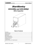
VANNER Incorporated Owner’s Manual VLT Series 600 Watt True Sine Wave Inverter Pure Sine Wave Inverter ON INPUT LEVEL I 0 LOAD LEVEL OFF FAULT AC OUTPUT FREQ. 50Hz 60Hz Models VLT12-600 VLTE12-600 VLT24-600 VLTE24-600 600 Watt VLT Series Inverter Owner’s Manual -1- VANNER Incorporated Owner’s Manual TABLE OF CONTENTS 1 INTRODUCTION ................................................................................... 3 2 IMPORTANT SAFETY INSTRUCTIONS .............................................. 3 2.1.1 2.1.2 General Safety Precautions ........................................................................................................ 3 Precautions When Working With Batteries ............................................................................... 4 3 SPECIFICATIONS AND FEATURES ................................................... 5 3.1.1 3.1.2 3.1.3 3.1.4 Specifications ............................................................................................................................. 5 Front Panel ................................................................................................................................. 6 AC Output GFCI Duplex Receptacle ......................................................................................... 7 Rear Panel .................................................................................................................................. 7 4 INSTALLATION .................................................................................... 9 4.1.1 DC Cable and Fuse Sizing Chart .............................................................................................. 10 5 TROUBLESHOOTING ........................................................................ 11 6 MAINTENANCE .................................................................................. 11 -2- 600 Watt VLT Series Inverter Owner’s Manual VANNER Incorporated Owner’s Manual 1 INTRODUCTION Thank you for purchasing a Vanner 600 Watt VLT SERIES Inverter. We are confident that you will be satisfied with the inverter’s performance and its many features. With proper installation and care, you can look forward to years of service from this high performance product. This document will describe the operation, technical specifications and installation procedures. 2 IMPORTANT SAFETY INSTRUCTIONS Electrocution hazard exists Fire hazard exists A potentially dangerous condition Explosive hazard exists Corrosive hazard exists To get the most out of the power inverter, it must be installed and used properly. Please read the instructions in this manual before installation. Keep this manual for future reference. 2.1.1 General Safety Precautions Do not expose the inverter to rain, snow, spray, or dust. To reduce risk of hazard, do not obstruct the ventilation openings. Do not install the inverter in a zero-clearance compartment. Overheating may result. To avoid a risk of fire and electric shock, make sure the wiring is in good electrical condition and is proper gauge. Do not operate the inverter with damaged or substandard wiring. This equipment contains components that can produce arc or sparks. To prevent fire or explosion, do not install in compartments containing batteries or flammable materials or in locations which require ignition protected equipment This includes any space containing gasoline-powered machinery, fuel tanks, or joints, fittings, or other connection between components of the fuel system 600 Watt VLT Series Inverter Owner’s Manual -3- VANNER Incorporated Owner’s Manual 2.1.2 Precautions When Working With Batteries If battery acid contacts skin or clothing, wash immediately with soap and water. If acid enters eye, immediately flood eye with running cold water for at least 20 minutes and get medical attention immediately. Never smoke or allow a spark or flame in vicinity of battery or Engine. Do not drop a metal tool onto the battery. The resulting spark or short-circuit on the battery or other electrical part may cause an explosion. Remove personal metal items such as rings, necklaces, and watches when working with a leadacid battery. A lead-acid battery can produces a short-circuit current high enough to weld a ring or the like to metal, causing severe burns. 1 -4- 600 Watt VLT Series Inverter Owner’s Manual VANNER Incorporated Owner’s Manual 3 SPECIFICATIONS AND FEATURES 3.1.1 Specifications Model Number SPECIFICATIONS VLT12-600 VLT24-600 VLTE12-600 VLTE24-600 AC Power Output Rated Continuous Output 600 Watts Surge Rating (3S) A 6.67 3.33 Output Waveform True Sine Wave Total Harmonic Distortion Output Voltage Output Frequency AC Output Wiring Method Maximum, Efficiency % DC Input Voltage DC Input Voltage Range Low DC voltage Shutdown / Restart High DC voltage Shutdown / Restart < 3% THD 120 VAC +/- 3% 230 VAC +/- 3% 60 Hz ± 0.05% 50 Hz ± 0.05% 88 12V Nominal 11.5 to 16.0 11.3 / 13.5 16.3 / 15.8 GFCI Duplex Receptacle 90 92 24V Nominal 12V Nominal 23.0 to 32.0 11.5 to 16.0 22.5 / 26.5 11.3 / 13.5 32.6 / 31.5 16.3 / 15.8 94 24V Nominal 23.0 to 32.0 22.5 / 26.5 32.6 / 31.5 DC Input Current Inverter ON with no AC load < 1A System Overload, Short Circuit, Reverse Polarity (internal nonreplaceable fuse), Over/Under Input Voltage, Over Temperature Protection Safety UL458 Remote Control ON/OFF Control by customer supplied external switch Ambient Operating Temperature -25 +50ºC (-13 to +122ºF) Storage Temperature -30 to +70ºC (-22 to 158ºF) Fan Cooling Thermostatically controlled cooling fan Enclosure Painted aluminum Dimensions (L x W x H) Weight 11.0” L x 7.25” W x 3.0” H 6.6 pounds 600 Watt VLT Series Inverter Owner’s Manual -5- VANNER Incorporated Owner’s Manual 3.1.2 Front Panel Pure Sine Wave Inverter ON INPUT LEVEL I 0 LOAD LEVEL OFF FAULT AC OUTPUT FREQ. 50Hz 60Hz 3.1.2.1 ON / OFF Control Switch The ON/OFF Switch must be in the ON position when using Remote Control. 3.1.2.2 Input Level LED LED Display and Color 12Vdc 24Vdc Slow Red Blink 10.10 to 11.10 21.0 to 21.8 Red 11.10 to 11.60 21.8 to 22.6 Orange 11.60 to 13.20 22.6 to 24.0 Green 13.20 to 15.20 24.0 to 28.0 Orange Blink 15.20 to 16.00 28.0 to 29.4 Red Blink 16.00 to 16.20 29.4 and above Red Fault 16.20 and above 3.1.2.3 Load Level LED LED Display and Color Dark Load Condition 0 ~ 30W Green 30W ~ 200W Orange 200W ~ 450W Red 450W ~ 580W Red Blink -6- Over 580W 600 Watt VLT Series Inverter Owner’s Manual VANNER Incorporated Owner’s Manual 3.1.3 AC Output GFCI Duplex Receptacle The AC output neutral conductor is connected to AC ground and inverter chassis ground inside the inverter. This conforms to National Electrical Code requirements that separately derived AC sources (such as inverter and generators) have their neutral conductors tied to ground in the same way that the neutral conductor from the utility is tied to ground at the AC breaker panel. Do not connect AC neutral to AC ground downstream of the GFCI. This would cause the GFCI to trip. Never connect the inverter output to another AC power source such as a generator or utility power. The inverter would be destroyed. 3.1.4 Rear Panel DC INPUT Vout Vin WARNING: REVERSE POLARITY WILL DAMAGE UNIT. REMOTE CONTROL NEG (-) POS (+) CHASSIS GROUND 3.1.4.1 DC Input Terminals DC Input terminals are for the included 6AWG ring terminals. The ring terminal entry is limited to a maximum of 4AWG wire. Connect DC Input Terminals to a 12v battery (24v battery for 24v units). (+) is positive,(-) is negative. Reverse polarity connection will blow the internal fuses and may cause permanent damage to the inverter. 3.1.4.2 Chassis Ground Bonding Lug Connect Chassis Ground Bonding Lug to vehicle chassis using 12AWG or larger copper wire. 3.1.4.3 Fan Do not obstruct the rear fan exhaust or front ventilation intake openings. Allow at least 3 inches of clearance for airflow. 3.1.4.4 Remote Control Terminal A green two-terminal connector located on the front panel allows remote ON/OFF control of the inverter by a customer-supplied ON/OFF switch. Standard Operation (Not using remote control): The inverter is shipped with a jumper connecting terminals Vout and Vin. With the jumper in place (remote control not being used) the inverter is fully functional using the ON/OFF Control Switch located on the front of the inverter. 600 Watt VLT Series Inverter Owner’s Manual -7- VANNER Incorporated Owner’s Manual Remote Control via customer-supplied SPST switch: If it is desired to remotely control the inverter from a customer-supplied remote switch, remove the jumper connecting terminals Vout and Vin. Supply a 12v (24v signal on 24v units) continuous signal to terminal Vin to turn the inverter ON. The source of the 12v signal can be battery voltage for single-wire remote control or terminal Vout for two-wire-remote-control. The most common remote control wiring arrangement uses a "hot in run" circuit from the vehicle fuse panel for the 12v signal. This arrangement automatically turns the inverter ON when the vehicle is ON and automatically turns the inverter OFF when the vehicle is OFF. Green Connector Details: Terminal Vout is current limited, therefore if terminal Vout is used as the source for the remote control signal, a fuse is not required in the remote control circuit. If Vout is not used as the remote control signal, use a 5 amp fused circuit for the remote control signal. The green connector can be removed from the inverter by pulling the connector outward. The two upward facing screws are used to tighten the compression terminals for attachment of the signal wire(s). Torque to 4 lb-in max 3.1.5 Measurements -8- 600 Watt VLT Series Inverter Owner’s Manual VANNER Incorporated Owner’s Manual 4 INSTALLATION Inverter Installation Considerations Mounting: Locate a flat secure, dry, horizontal or vertical surface large enough to mount the inverter. The location should be as close to the battery as practical, usually within six feet, but not in the same compartment and should provide adequate ventilation while the inverter is operating. The location must be clean, dry and free from road spray, dripping water or other moisture contamination. Cooling Fan Clearance: The mounting location must allow unobstructed airflow for cooling. Allow a minimum clearance of 3 inches on the front and back of the inverter. The Cooling Fan is thermostatically controlled. Obstruction of the fan exhaust or the front intake vents will diminish the inverter output capacity due to overheating. DC Wiring Considerations Do not connect the 12V model to a 24V battery. The unit will be destroyed immediately. Operation of the inverter without a proper ground connection may result an electrical safety hazard. Damage caused by reversed polarity will void warranty. A DC FUSE IS REQUIRED to protect the DC cables in case of a short circuit. The wiring of the inverter installation should conform to the National Electric Code (NEC) and any other state or local codes in effect at the time of installation. Article 551 of the NEC requires any DC cable from a battery, which measures longer than 18 inches along its length, be protected by a fuse. BE AWARE, as a large number of capacitors become charged upon completion of the DC circuit, THERE WILL BE A LARGE SPARK when the last battery connection is made. The spark is normal and will occur every time the batteries are connected. It is advisable to make the last DC connection at the inverter, not at the battery, to reduce the risk of battery explosion. To minimize electromagnetic radiation that could interfere with sensitive electronics, route the AC output wiring and DC power wiring with as much physical separation as possible from low voltage wiring such as audio and video signal wires. Route the DC positive and negative cables as close together as possible and use cable ties to keep them together. If passing through steel or other ferrous metal walls, the DC input cables need to pass through the same hole to prevent causing a transformer effect. If two holes are required, cut a slot to connect the two holes to prevent heating of the ferrous metal. Proper DC cable size is critical for the performance and safe operation of the inverter system. The DC Cable and Fuse Sizing Chart shows the minimum cable sizes recommended. These sizes allow a ½ volt maximum voltage drop at maximum inverter capacity and will insure optimum inverter performance. DC cable to be used with these fuse sizes should be minimum insulation temperature rating of 105°C and voltage rating of 600V. DC cables should be as short as possible. Do not use the vehicle chassis as the DC negative conductor. The negative cable should be the same size as the DC positive cable and should be connected directly to the battery negative terminal. 600 Watt VLT Series Inverter Owner’s Manual -9- VANNER Incorporated Owner’s Manual 4.1.1 DC Cable and Fuse Sizing Chart Model Number VLT12-600 VLT24-600 Distance from battery to inverter in feet (Total circuit length is 2 times the distance.) Wire Size 8 6 4 Fuse Rating 6.5 10.0 16.0 80 Amp 13.5 20 20 60 Amp Fuse Part Number 013910 013909 Fuse Holder Part Number 013780 DC Wiring Installation Procedure Verify the Power ON/OFF Switch is in the OFF position before connecting inverter to the battery. Route the negative DC cable to the battery. Verify cable polarity before proceeding. The fuse will be blown and inverter may be damaged if the DC cables are reversed. Route the positive DC cable to the fuse and then to the battery. Protect cables with loom and use grommets or other appropriate means where cables may contact hard, sharp edges. Connect Chassis Ground Bonding Lug to the vehicle chassis and/or earth ground using 8AWG or larger copper wire. (The wire must be sized to safely carry DC current as needed to blow the DC fuse located near the battery in the inverter’s positive DC input cable.) - 10 - 600 Watt VLT Series Inverter Owner’s Manual VANNER Incorporated Owner’s Manual 5 TROUBLESHOOTING WARNING! Do not open or disassemble the Inverter. Attempting to service the unit yourself may result in a risk of electrical shock or fire, and will void warranty. Problems and Symptoms Possible Cause Solutions No AC output voltage accompanied by the following Power Status LED flash pattern. Blinking Red Fast. High DC input voltage. Blinking Red Slowly. Low DC input voltage. Blinking Red, Flashing Two Over temperature shut down ON Solid Red Overload, short circuit 6 Check input voltage. Reduce input voltage. Recharge battery. Check connections and cable. Improve ventilation. Make sure inverter ventilation openings are not obstructed. Reduce ambient temperature. Remove AC load. Check AC wiring for short circuit.. MAINTENANCE Very little maintenance is required to keep the inverter operating properly. Clean the exterior of the unit periodically with a damp cloth to prevent accumulation of dust and dirt. At the same time, verify the battery and fuse connections are clean and tight. Test and reset the GFCI monthly. 600 Watt VLT Series Inverter Owner’s Manual - 11 - VANNER Incorporated Owner’s Manual Vanner Incorporated 4282 Reynolds Drive Hilliard, Ohio 43026 Ph: 800-AC POWER Ph: 614-771-2718 Fax: 614-771-4904 www.vanner.com Manual P/N: D916054-A - 12 - 600 Watt VLT Series Inverter Owner’s Manual