1
~ £ R II
~
"
}
..
~
~
J.-:;~~J
1ft
..,
~
o
q
it'D""
OPERATORS MANUAL
FOR THE
4.5KW BeGB - 60HZ
3.8KW BeGB - 50Hz
AND
7.0KW BeGB - 60HZ
5.0KW BeGB - 50Hz
GASOLINE GENERATORS
SINGLE PHASE
PUBLICATION NO.44200
JUNE 1999
1ST EDITION
WESTERBEKE CORPORATION
MYLES STANDISH INDUSTRIAL PARK
150 JOHN HANCOCK ROAD, TAUNTON, MA 0278fJ.7319
....
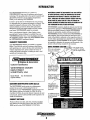
Gasoline with an ETHANOL content
higher than 10% (E10) is not allowed
and may void warranty.
Engines & Generators
A
WARNING:
&fIa1lSl gasses cotrtain Ciut10n Monoxide, an odorless and
colorless gas. Carbon Monoxide Is poisonous and can cause
unconselousness and death. Symptoms of Carbon Monoxide
ezposufll can Include:
-Dizziness
- Throbbing In Temples
-Nausea
- Museular Twitching
-lIBadachfJ
- Vomiting
- Weakness and Sleepiness -Inability to Thinlc Coherently
IF YOU OR ANYONE EI.SE EXPERIENCE ANY DF THESE SYMl'TDMS,
SET OUT INTO THE FRESH AIR IMMEDIATELY. "symptoms persist,
sesJc medical attention. Shut down tIIB unit and do not fIIStaJt
until It has been Inspected and fllpalred.
,,,.,WESTERBEKE
I Engines & Generators
Engines & Generators
Declaration of Conformity
Application of Conncil Directive(s)
EMC 89/336IEEC
ISO 8846 1990(E)
Standard(s) to Which Conformity
is declared
ENS0081-1
ENS0082-2
ENSS020
ISO-8846-1990(E), Certification
Number, IWES003
Manufacturers Name
Westerbeke Corporation
Manufacturers Address
150 John Hancock Road
Myles Standish Industrial Park
Taunton, Ma. 02780-7319, USA
Type of Equipment
Marine Gasoline Generator
Product Name
Westerbeke Marine
Gasoline Generator
Model(s)
3.SBCGB-SI4, 4.SBCGB-614
S.OBCGB-SI4, 7.0BCGB-614
Product Options
All
Supplementary Information
1.) The equipment listed is only for use in Marine Applications aboard boats.
2.) The equipment listed must be located below decks on the vessel and
permanently installed in it's location.
3.) The equipment listed must be wired to the grounding system of the vessel.
I the undersigned, hereby declare that the equipment specified above conforms to
the above Directive(s) and Standard(s).
Place Taunton. Massachusetts, U_S_A
Date: January 1, 2001
042022
Carleton F. Baant
(Full Name)
Chief Operating Officer
(Title)
WESTERBEKE CORPORATION
MYLES STANDISH INDUSTRIAL PARK, 150 JOHN HANCOCK ROAD, TAUNTON, MA 02780-7319· TEL 508-823-76n· FAX 508-884-9688· WEBSITE: WWW.WESTEABEKE.COM
INTERNATIONAL MARINE CERTIFICATION INSTITUTE
Rond Point SchulMn II, Box tI
8 - 1040 BRUXELLES
BELGIQUE
1lI1: (32) 2-238-1892
fmc: (32) 2-2S8-770D
CERTIFICATE
We hereby certify the component stated below meets the EC Directive 94125/EC for
EC type-examination in accordance with ISO 8846 and has following characteristics:
TYPE
MANUFACTURER
ADDRESS
GROUP OF
Modell
Model 2
Model 3
Model 4
ModelS
ModelS
Model 7
ModelS
Model 9
Model 10
Model 11
Model 12
Model 13
Model 14
Model 15
ModellS
Model 17
ModellS
Model 19
Model 20
Model 21
Model 22
Model 23
.
3.5/4.5 BCGB
5.017.0 BCGB
+++++
Gasoline Marine Generator
Westerbeke Corp.
Avon Industrial Park,
AVON, MA02333
USA
+++++
+++++
.:;-
+++++
+++++
+++++
+++++
+++++
+++++
+++++
+++++
+++++
+++++
+++++
+++++
+++++
+++++
+++++
+++++
+++++
+++++
+++++
+++++
+++++
+++++
+++++
+++++
+++++
+++++
+++++
+++++
+++++
+++++
+++++
+++++
+++++
+++++
+++++
+++++
+++++
+++++
+++++
+++++
+++++
+++++
+++++
+++++
+++++
+++++
+++++
+++++
+++++
+++++
+++++
+++++
+++++
+++++
+++++
+++++
+++++
+++++
+++++
+++++
+++++
+++++
+++++
+++++
+++++
+++++
SAFETY INSTRUCTIONS
INTRODUCTION
PREVENT BURNS - FIRE
Read this safety manual carefuUy. Most accidents are
caused by failure to folJow fundamenJal rules and precautions. Know when dangerous condiJions exist and Iilke the
necessary precautions to protect yourself, your personne4
and your machinery.
The foUowing safety instructions are in compliance wiJh the
American Boat and Yacht Council (ABYC) standards.
IA WARNING:
PREVENT ELECTRIC SHOCK
•
A WARNING: I1D not touch AC electrical cotmeCtions
willie B/lgllIB Is IUMlng, or wlrBII connected to shore
p/JWf1r. LBthaI roltage is PrBSllnt at thBSB COllllllctiOIlS!
•
•
•
• Do not operate this machinery without electrical
•
•
enclosures and covers in place.
Shut off electrical power before accessing electrical
equipment
Use insulated mats whenever working on electrical
equipment
•
Remove wristwatch and all jewelry when working on
electrical equipment
Do not connect utility shore power to vessel's AC
circuits, except through a ship-t(}-shore double throw
transfer switch. Damage to vessel's AC generator may
result if this procedure is not followed.
Electrical shock results from handling a charged capacitor. Discharge capacitor by shorting terminals together.
A WARNING: EzplosiollS from fuel rapors can cause
Injury Dr death!
•
•
PREVENT BURNS - HOT ENGINE
•
•
A WARNING: Do not touch hot engine parts Dr
exhaust system components. A IUMing engine gets
reryhot!
•
Always check the engine coolant level at the coolant
recovery tank.
IA WARNING:
•
Do not smoke or permit flames or sparks to occur near
the fuel system. Keep the compartment and the
engine/generator clean and free of debris to minjmize the
chances of fire. Wipe up all spilled fuel and engine oil.
PREVENT BURNS - EXPlOSION
Make sure your clothing and skin are dry, not damp
(particularly shoes) wben handling electrical equipment
•
Prevent flash fires. Do not smoke or permit Oames or
sparks to occur near the carburetor, fuel line, filter, fuel
pump, or other potential sources of spilled fuel or fuel
vapors. Use a suitable container to catch all fuel when
removing the fuel line, carburetor, or fuel filters.
Do not operate with a Coast Guard Approved Oame
arrester removed. Backfire can cause severe injury or
death.
Do not operate with the air cleaner/silencer removed.
Backfire can cause severe injury or death.
• Be aware - diesel fuel will hom.
•
•
Fire can cause injury Dr death!
Steam can cause Injury Dr death!
In case of an engine overheat, allow the engine to cool
before touching the engine or checking the coolant
•
•
•
•
Follow re-fueling safety instructions. Keep the vessel's
hatches closed when fueling. Open and ventilate cabin
after fueling. Check below for fumes/vapor before run·
ning the blower. Run the blower for four minutes before
starting your engine.
All fuel vapors are highly explosive. Use extreme care
when handling and storing fuels. Store fuel in a well-ventilated area away from spark-producing equipment and
out of the reach of children.
Do not fill the fuel rank(s) while the engine is running.
Shut off the fuel service valve at the engine when servicing
the fuel system. Take care in catching any fuel that might
spill. DO NaT allow any smoking, open flames, or other
sources of fire near the fuel system or engine when servicing. Ensure proper ventilation exists when servicing the
fuel system.
Do not alter or modify the fuel system.
Be sure all fuel supplies have a positive shutoff valve.
Be certain fuel line fittings are adequately tightened and
free of leaks.
Make sure a fire extinguisher is installed nearby and is
properly maintained. Be familiar with its proper use.
Extinguishers rated ABC by the NFPA are appropriate
for all applications encountered in this environment
1~IWES7ERBEKE
I Engines & Generators
i
(
SAFETY INSTRUCTIONS
ACCIDENTAL STARTING
TOXIC EXHAUST GASES
A WARNING: Accidental starting can cause injury
A WARNING: Carbon monoxide (CO) is a deadly gas!
orduth!
•
•
•
Ensure that the exhaust system is adequate to expel gases
discharged from the engine. Cbeck the exhaust system
regularly for leaks and make sure the exhaust manifolds
are securely attached and no warping exists. Pay close
anention to the manifold, water injection elbow, and
exhaust pipe nipple.
Be sure the unit and its surroundings are well ventilated.
In addition to routine inspection of the exhaust system,
install a carbon monoxide detector. Consult your boat
builder or dealer for installation of approved detectors.
For additional information refer to ABYC T-22 (educational information on Carbon Monoxide).
•
Disconnect the banery cables before servicing the engine!
generator. Remove the negative lead first and reconnect
it last
Make cenain all personnel are clear of the engine before
starting.
Make certain all covers, guards, and batches are reinstalled before starting the engine.
•
•
BATTERY EXPLOSION
•
A WARNING: Battsry explosion can cause injury
orduth!
•
•
•
•
A WARNING: Carbon monoxide (CO) is an Invisible
Do not smoke or allow an open flame near the battery
being serviced. Lead acid baneries emit hydrogen, a
highly explosive gas, which can be ignited by electrical
arcing or by lit tohaceo products. Shut off all electrical
equipment in the vicinity to prevent electrical arcing during servicing.
Never connect the negative (-) banery cable to the positive (+) connection terminal of the starter solenoid. Do
not test the battery condition by shorting the terminals
together. Sparks could ignite battery gases or fuel vapors.
Ventilate any compartment containing baneries to prevent
accumulation of explosive gases. To avoid sparks, do not
disturb the banery charger connections while the banery
is being charged.
Avoid contacting the terminals with tools, etc., to prevent
burns or sparks that could cause an explosion. Remove
wristwatch, rings, and any other jewelry before handling
the banery.
Always turn the battery charger off before disconnecting
the banery connections. Remove the negative lead first
and reconnect it last when disconnecting the battery.
odorless gas. Inhalation produces flu·like symptoms,
nausea or death!
•
•
•
fumes can rapidly destrOy copper tubing in exhaust systems. Exhaust sulfur causes rapid deterioration of copper
tubing resulting in exhaust/water leakage.
Do not install exhaust outlet wbere exhaust can be drawn
through portholes, vents, or air conditioners. If the engine
exhaust discharge outlet is near the waterline, water could
enter the exhaust discharge outlet and close or restrict the
flow of exhaust Avoid overloading the craft.
Although diesel engine exhaust gases are not as toxic as
exhaust fumes from gasoline engines, carbon monoxide
gas is present in diesel exhaust fumes. Some of the symptoms or signs of carbon monoxide inhalation or poisoning
are:
Vomiting
Dizziness
Throbbing in temples
Muscular twitching
Intense headache
Weakness and sleepiness
BATTERY ACID
A WARNING: SUlfuric acid In batteries can cause
serere Injury or death!
•
Do not use copper tubing in diesel exhaust systems. Diesel
AVOID MOVING PARTS
When servicing the banery or checking the electrolyte
level, wear rubber gloves, a rubber apron, and eye protection. Baneries contain sulfuric acid which is destructive.
If it comes in contact with your skin, wash it off at once
with water. Acid may splash on the skin or into the eyes
inadvertently when removing electrolyte caps.
~
A WARNING: Rotating parts can cause Injury
or death!
•
Do not service the engine while it is running. If a situation arises in which it is absolutely necessary to make
operating adjusbnents, use extreme care to avoid touching
moving parts and hot exhaust system components.
WESTERBEKE
Engines & Generators
ii
(
SAFETY INSTRUCTIONS
•
•
ABYMFPA AND USCG PUBLICATIONS FOR
INST NG DlESa ENGINES
Do not wear loose clothing or jewelry when servicing
equipment; tie back long hair and avoid wearing loose
jackets, shirts, sleeves, rings, necklaces or bracelets that
could be caught in moving parts.
Read the following ABYC, NFPA and USCG publications
for safety codes and standards. Follow their recommendations when installing your engine.
Make sure all attaching hardware is properly tightened.
Keep protective shields and guards in their respective
places at all times.
•
Do not check fluid levels or the drive belt's tension while
the engine is operating.
•
Stay clear of the drive shaft and the transmission coupling
when the engine is running; hair and clothing can easily
be caught in these rotating parts.
ABYC (American Boat and Yacht Council)
"Safety Standards for Small Craft"
Order from:
ABYC
15 East 26th Street
New York, NY 10010
NFPA (National Fire Protection Association)
"Fire Protection Standard for Motor Craft"
HAZARDOUS NOISE
Order from:
A WARNING: High noise levels can cause hearing
National Fire Protection Association
II Tracy Drive
Avon Indusaial Park
Avon, MA 02322
loss!
•
Never operate an engine without its muffler installed.
•
Do not run an engine with the air intake (silencer)
removed.
USCG (Urtited States Coast Guard)
"USCG 33CFR183"
•
Do not run engines for long periods with their enclosures
open.
Order from:
U.S. Government Printing Office
Washington, D.C. 20404
A WARNING: 00 not wade on machine/), when you are
mentally or physically incapacitated by fatigue!
OPERATORS MANUAl.
Many of the preceding safety tips and wamings are repeated
in your Operators Manual along with other cautions and
notes to highlight critical information. Read your manual
carefully, maintain your equipment, and follow all safety
procedures.
GASOLINE ENGINE AND GENERATOR
INSTAllATIONS
Preparations to install a gasoline engine or generator should
begin with a thorough examination of the American Boat and
Yacht Council's (ABYC) standards. These standards are from
a combination of sources including the USCG and the NFPA.
Sections of the ABYC standards of particular interest are:
H-2 Ventilation
H-24 Gasoline fuel systems
P-I Exhaust systems
P-4 Inboard engines
E-9 DC Elecaical systems
All installations must comply with the Federal Code of
Regulations (FCR).
~
WESTERBEKE
Engines & Generators
iii
(
INSTALLATION
When installing WESTERBEKE engines and generators it is important that strict
attention be paid to the following information:
CODES AND REGULATIONS
Strict federal regulations, ABYC guidelines, and safety codes must be complied with'
when installing engines and generators in a marine environmenl
SIPHON-BREAK
For installations where the exhaust manifold/water injected exhaust elbow is close to
or will be below the vessel's waterline, provisions must be made to install a siphonbreak in the raw water supply hose to the exhaust elbow. "This hose must be looped a
minimum of 20" above the vessel's waterline. Failure to use a siplwn-break when
the exhaust manifold injection port is at or beww tM /oad waterline will result in
raw water damage to the engine and possible flooding of the boaL
If you have any doubt about the position of the water-injected exhaust elbow relative
to the vessel's waterline under the vessel's various operating conditions, install a
siphon-break
NOTE: A siphon-break requires periodic inspection and cleaning to ensure proper
operarion. Failure to properly maimain a siphon-break can result in catastrophic
engine damage. Consult the siphon-break manufacturer for proper maintenance.
EXHAUST SYSTEM
The exhaust hose must be certified for marine use. The system must be designed to
prevent water from entering the exhaust under any sea conditions and at any angle
of the vessels hull.
A detailed 40 page Marine Installation Manual covering gasoline and
diesel, engines and generators, is available from your WESTERBEKE
dealer.
-..v- WESTERBEKE
Engines & Generators
iv
(
TABLE OF CONTENTS
Parts Identification ................................................2
Introduction ............................................................. 3
Engine Adjustments ............................................ .26
Speed Hertz AdjustmenL ............................... 26
Torquing the Cylinder Head Bolts ................ 26
Spark Plugs ......... '" ......................................... 27
Drive Belt Adjustment... ................................. 27
Valve Clearance . '" ......................................... 28
Choke Solenoid .............................................. 28
Timing Belt ..................................................... 29
Engine Compression ..................................... .32
Component Testing ........................................... .33
Engine Troubleshooting ............. '" .................... .34
Generator Information ...................................... .36
Serial Number Location .................................. .3
Fuel, Engine Oil and Engine CoolanL ............... 5
Control Panels .....................................................6
Preparations for Initial Start.Up .........................7
Operating Instructions ........................................ 8
Remote Panel ................................................. 9
Break·ln Procedure/Daily Operation ................. 10
Safety Shutdown Switches ................................ 11
Maintenance Schedule .................... '" .............. 12
BC Generator Single Phase ...............................37
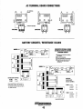
AC Terminal Board Connections ..................... ..40
Battery Circuit/Resistance Values ...................40
BC Generator Single Phase ...............................41
Testing Component Resistance .................... ..42
Integral Controller ........................................ ..43
Testing the Battery Charger ......................... ..43
Baery
tt Chargmg
. C·Ircul·t .....................................44
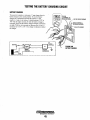
Testing the Battery Charging CircuiL ........... ..45
Shore Power Transfer Switch .......................... ..46
Lay·up and Recommissioning ......................... ..47
Generator Specifications '" ............................. ..49
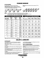
Standard Hardware ...........................................50
BCGB Hardware Torques ...................................51
Metric Conversions Chart .................................52
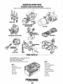
Suggested Spare Parts ......................................53
Cooling System .................................................. 14
Changing Coolant ........................................... 15
Thermostat ...................................................... 16
Heat Exchanger .............................................. 16
Raw Water Intake Strainer.. ............................ 17
Raw Water Pump ............................................ 17
Fuel System ....................................................... 18
Carburetor ....................................................... 18
Fuel Lift Pump ................................................ 18
Gasdenser. ....................................................... 18
GasolinelWater Seperator ............................... 18
Carburetor Adjustments .................................... 19
Engine Lubricating OiL ................................... .20
Oil Pressure .......................................................21
Remote Oil Filter ...............................................22
BCGB Wiring Diagram ........................................23
BCGB Wiring Schematic ............................ '" .....24
Remote Panel Wiring ......................................... 25
-..v- WESTERBEKE
Engines & Generators
1
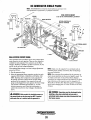
BCGB PARTS IDENTIFICATION
AIR INTAKE
ENGINE Oil Fill
PRESSURE CAP
WATER INJECTED
EXHAUST ELBOW
REMOTE PANEL
CONNECTION
CIRCUIT BREAKER
COOLANT DRAIN
GENERATOR
BACKEND
REAR
Oil PAN
LEFT SIDE
'HI,XI'"
MOUNT
CARBURETOR
RIGHT SIDE
HOURMETER
ENGINE Oil Fill
~~3i\t----- RAW WATER
CONTROL _---~::;;;::~:...~
SWITCHES-
INJECTION
(SYPHON BREAK
CONNECTION)
8 AMP FUSE
25 AMP CIRCUIT
BREAKER
START MOTOR
Oil FilTER
OC GROUND
STUD
FUEL LIFT PUMP
HEAT EXCHANGER
FRONT
Engines & Generators
2
INTRODUCTION
WESTERBEKE CANNOT BE RESPONSIBLE FOR THE CONTENT
OF SUCH SOFTWARE, MAKES NO WARRANTIES OR REPRESENTATIONS WITH RESPECT THERETO, INCLUOING ACCURACY, TIMELINESS OR COMPLETENESS THEREOF ANO Will
IN NO EVENT BE LIABLE FOR ANY TYPE OF OAMAGE OR
INJURY INCURRED IN CONNECTION WITH OR ARISING OUT OF
THE FURNISHING OR USE OF SUCH SOFTWARE.
This WES1ERBEKE Generator is a product of
WES1ERBEKE'S long years of experience and advanced
technology, We take great pride in the superior durability and
dependable performance of our engines and generators.
Thank you for selecting WES1ERBEKE.
In order to get the full use and benefit from your generator,
it is important that you operate and maintain it correctly. This
manual is designed to help you do this. Please read this
manual carefully and observe all the safety precautions
throughout. Should your engine require servicing, contact
your nearest WES1ERBEKE dealer for assistance.
WES1ERBEKE customers should also keep in mind the time
span between printings ofWES1ERBEKE product software
and the unavoidable existence of earlier WES1ERBEKE
manuals. In summation, product software provided with
WES1ERBEKE products, whether from WES1ERBEKE or
other suppliers, must not and cannot be relied upon exclusively as the definitive authority on the respective product It
not only makes good sense but is imperative that appropriate
representatives of WES1ERBEKE or the supplier in question
be consulted to determine the accuracy and currentness of the
This is your Operators Manual. A Parts Catalog is also
provided and a Technical Manual is available from your
WES1ERBEKE dealer. Also, if you are planning to install
this equipment yourself, contact your WES1ERBEKE dealer
for WES1ERBEKE'S Installation Manual.
WARRANTY PROCEDURES
product software being consulted by the customer.
Your WES1ERBEKE Warranty is included in a separate
folder. If you have not received a customer identification
LOCATIDN~'\
SERIAL NUMBER
The engine serial
Fill in the information .
1~(,~Ob'l-;:\ . ,!umber is stamped
below for reference. ~i"''''
\1 mto the engme block.
card registering your warranty 60 days after submitting the
warranty registration fonn, please contact the factory in
writing with model information, including the unit's serial
0~
number and commission date.
f'''
I~
~f--
7",
~I
~
II''*'
I~'WESTERBEKE
:I'~\
, Engines & Generators
.
Customer Identification
,
~~;a~~=~
The engine model
'. and
II serial
number
number are printed
on a decal on the
WESTERBEKE OWNER
MAIN STREET
HOMETOWN, USA
engine manifold.
The gen~rator serial
Model BeGB Ser. #D703XXXX
Expires 9/20/02
number IS stcllnp"d
on the top
generator hOI~~~
CUSTOMER IDENTIFICATION CARD (Typical)
The Itenerator
specifications are
The WES1ERBEKE serial number is an alphanumeric
number that can assist in determining the date of
manufacture of your WES1ERBEKE engine/generator. The
first character indicates the decade (A=1960s, B=1970s,
C=1980s, D=1990s), the second character represents the year
in the decade, and the fourth and fifth number represents the
month of manufacture.
printed on a decal
on the side of the
generator.
An additional decal
is located on the top
of the generator
housing.
PRODUCT SOFTWARE
Product software (tech data, parts lists, manuals, brochures
and catalogs) provided from sources other than WES1ERBEKE are not within WES1ERBEKE'S CONTROL.
Engines & Generators
3
INTRODUCTION
ORDERING PARTS
PROTECTING YOUR INVESTMENT
Whenever replacement parts are needed, always provide the
generator and engine model and serial numbers. In addition,
include a complete part description and part number for each
part needed (see the separately furnished Parts Catalog). Also
insist upon WESTERBEKE packaged parts because will fit
or generic parts are frequently not made to the same specifications as original equipment.
Care at the factory during assembly and thorough testing
have resulted in a WESTERBEKE generator capable of
many thousands of hours of dependable service. However the
manufacturer cannot control how or where the generator is
installed in the vessel or the manner in which the unit is
operated and serviced in the field. This is up to the
buyer/owner-operator.
NOTE: Six important steps to ensure long generator life:
NOTES, CAUTIONS AND WARNINGS
• Proper engine and generator installation and alignment.
As this manual takes you through the operating procedures,
maintenance schedules, and troubleshooting of your generator, critical information will be highlighted by NOTES,
CAUTIONS, and WARNINGS. An explanation follows:
• An efficient well.designed exhaust system that includes
an anti-siphon break to prevent water from entering the
engine.
NOTE: An operating procedure essential to note.
A
• Changing the engine oil and oil filters every 100 operat·
inghours.
• Proper maintenance of all engine and generator components according to the maintenance schedule in this
manuaL
CAUTION: Procedures, which if not strictly
observed, can result in the damage or destruction of
the engine or generator.
• Use clean,filtered unleadedfueL
• Winterize your engine according to the "Lay·up and
Recommissioning" section in this manual
A
WARNING: Procedures, which if not properly
followed, can result in personal injury or loss of life.
UNDERSTANDING THE GASOLINE GENERATOR
The gasoline engine driving an AC generator is in many
ways similar to a gasoline automobile engine. The cylinders
are verticle in-line, and the engine's cylinder head has an
overhead camshaft which is chain-driven. The engine utilizes
a solid-state distributor which is horizontally mounted and
camshaft-driven. The engine incorporates a pressure type
lubrication system, and a fresh water-cooled engine block
which is thermostatically-controlled. To a large degree, the
generator's engine requires the same preventive maintenance
that is required of a gasoline automobile engine. The most
important factors to the generator's longevity are proper
ventilation, maintenance of the fuel system, ignition system,
cooling system and the generator backend.
NOTE: A carbon monoxide warning decal has been provided
by WESTERBEKE. Affix this decal in a visable location in
the engine room.
SPARES AND ACCESSORIES
Certain spare parts will be needed to support and maintain
your WESTERBEKE generator or engine when cruising (see
SUGGESTED SPARE PARTS). Often even simple items such
as proper fuel and oil filter can be difficult to obtain along
the way. WESTERBEKE will provide you with a suggested
spares and accessories brochure to assist you in preparing an
on-board inventory of the proper WESTERBEKE parts.
"'" WESTERBEKE
Engines & Generators
4
FUEL, ENGINE OIL AND ENGINE COOLANT
GASOLINE
ENGINE COOLANT
Westerbeke recommends a mixture of 50% antifreeze and
50% distilled water, when possible. Distilled water is free
from the chemicals that can corrode internal engine surlaces.
A
CAUTION: Only use unleaded fuel with an
octane rating of 89 or higher. Leaded fuel will cause
The antifreeze performs double duty, as it allows the engine
to run at proper temperatures by transfening heat away from
the engine to the coolant. It also lubricates and protects the
cooling circuit from rust and corrosion. Use a good quality
antifreeze that contains supplemental cooling additives
(SCAs) that keep the antifreeze chemically balanced, crucial
to long term protection.
serious harm to your engine and violate your warranty.
CARE OF THE FUEL SUPPLY
Use only clean fuel! It is important to buy clean fuel, and
keep it clean. The best fuel can be rendered unsatisfactory by
careless handling or improper storage facilities. To assure that
the fuel going into the tank for your engine's daily use is
clean and pure, the following practice is advisable:
The water and antifreeze should be pre-mixed before being
poured into the cooling circuit.
Purchase a well-known brand of fuel.
NOTE: Use the new environmentally-jnendly long lasting
antifreeze that is now available.
Install and regularly service a good, Coast Guard approved
metal bowl type filter/water separator between the fuel tank
and the engine.
ANTIFREEZE PROTECTION CHART
Antifreeze concentration
ENGINE OIL
Freezing Temperature
Use a heavy duty engine oil with an API classification of SJ.
Change the engine oil after an initial 50 hours of break-in
operation, and every 100 hours of operation thereafter. For
recommended oil viscosity, see the following chart:
Operating Temperature
Oil Viscosity
Above 68° F (20° C)
SAE 30, 10W-30 or 15W-40
41° - 68° F (5°_20° C)
SAE 20 or 10W-30
Below 41° F (5° C)
SAE 10W-30
23%
30%
35%
50%
WF
8° F
_4° F
-40° F
(-WOC)
(-13°C)
(-20°C)
(-40°C)
COOLANT RECOVERY TANK
A coolant recovery tank kit is supplied with each generator.
The purpose of this recovery tank is to allow for engine
coolant expansion and contraction during engine operation,
without the loss of coolant and without introducing air into
the cooling system.
A
CAUTION: Do not aI/ow two or more brands of
engine oil to mix. Each brand contains its own addi·
tives; additives of different brands could react in the
mixture to produce properties harmful to your engine.
Engines & Generators
5
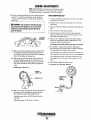
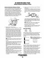
CONTROL PANELS
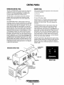
GENERATOR CONTROL PANEL
REMOTE PANEL
The ON and START/STOP switches are the only functional
There are three functional components on the remote panel
for generator operation:
components to operate the generator at the engine. Both
switches are used to start the generator - see Starting the
Generator under OPERATING INSTRUCTIONS.
1. ON switch
The ON switch is a two-position switch with momentary
contacts in the up (on) position and a stationary contact
function in the center position. This switch energizes the
fuel pump.
1. START/STOP switch
2. Green LED indicator light
The ON switch is a two-position switch with momentary
contacts in the up (on) position and a stationary contact
function in the center position. This switch energizes the
fuel pump.
The START/STOP switch is a three-position switch with
momentary contacts in the up (start) position and a stationary
contact function in the center and down (stop) positions. The
center (normal) position allows the generator to be run, once
started, and also enables the remote panel(s) to control the
start/stop functions. The up (start) position starts the generator
and once released, reverts to the center position. The down
§!Qp position stops the engine in nonnal operation as wen as
in an emergency situation, as it directly (unlike the remote
panel stop switch) controls power to the starter, fuel pump
The START/STOP switch is a three-position switch with
momentary contact functions in the up (start) and down
(stop) positions, and a stationary contact function in the
center position The center position is a dual OFFIRUN mode
position and is normally in the off mode. When in the start
(up) position, this switch starts the generator (together with
the ON switch in the up position) and once released, reverts
to the center position, run mode. When in the stop (down)
position, this switch stops the generator, and once released,
reverts to the center position, off mode:
and injector, and ignition relay coils, thus stopping the engine
should a malfunction occur. During times when maintenance
is being performed on the generator, the START/OFF switch
should be placed in the stationary (off) position. This will disable the remote control panel(s), preventing attempts to start
the generator from their locations. However, it is always best
to disconnect the battery during this time if it is not required
to perfonn the maintenance.
The Green LED indicator light indicates the engine running
condition. It lights when the ON switch is moved to the start
position, dims when the engine is cranking, and brightens
when the engine starts, notifying the operator to realease the
START switch.
25 AMP CIRCUIT
GENERATOR CONTROL PANEL
AMP FUSE
REMOTE
PANEL
CONNECTION
REMOTE PANEL
STOP
SWITCH
RECOROING HOURS
FOR MAINTENANCE
Engines & Generators
6
PREPARATIONS FOR INITIAL START-UP
PRESTART INSPECTION
Before starting your generator for the first time or after a prolonged layoff, check the following items:
• Check the engine oil level: add oil to maintain the level at
the full mark on the dipstick.
• Check the fuel supply and examine the fuel filter/separator
bowls for contaminants.
• Check the DC electrical system. Inspect wire connections
and battery cable connections.
• Check the coolant level in both the plastic recovery tank
and at the manifold.
MANIFOLD
PRESSURE
CAP
NOTE: After the initial running of the generator, the air in
the engine ~ cooling system will be purged to the coolant
recovery tank. Open the air bleed petcock to ensure that
the cooling system is purged of air. After shutdown and
after the engine has cooled, the coolant from the recovery
tank will be drawn into the engine ~ cooling system to
replace the purged air.
Before subsequent operation afthe generator; the engine:Smanifold should be topped off, and the coolant recovery
tank may need to be filled to the MAX level.
• Visually examine the unit. Look for loose or missing
parts, disconnected wires, unattached hoses, and check
threaded connections. Search for any gasoline leaks.
• Check load leads for correct connections as specified in
the wiring diagrams.
COOLANT RECOVERY TANK
• Examine the air inlet and outlet for air flow obstructions.
DIPSTICK
• Be sure no other generator or utility power is connected to
the load lines.
• Be sure that in power systems with a neutral line that the
neutral is properly grounded (or ungrounded) as the system
requires, and that generator neutral is properly connected
to the load neutral. In single phase systems an incomplete
or open neutral can supply the wrong line-ta-neutral
voltage on unbalanced loads.
A
MAX. LEVEL
1._",,,,__ OIL LEVEL
CAUTION: When starting the generator, it is
recommended that all AC loads, especially large
motors, be switched OFF until the engine has come up
to speed and, in cold climates, starts to warm up. This
precaution will prevent damage caused by unantici·
pated operation of the AC machinery and will prevent a
cold engine from stalling.
...v- WESTERBEKE
Engines & Generators
7
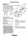
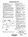
OPERATING INSTRUCTIONS
GENERATOR CONTROL PANEL
Starting the Generator
To start the generator, hold the momentary ON switch in the
up (on) position, then hold the momentary START/STOP
switch in the up (start) position (both switches are held up
together). After approximately one second, the starter will
engage and the engine will crank. Once the engine is
running, the starter will disengage, and the START/STOP
switch may then be released to return to its center (run mode)
position. Continue holding the ON switch until the engine has
sufficient oil pressure, then release it to its center position.
GENERATOR CONTROL PANEL
NOTE: Should the engine fail to start, release both switches,
wait 20 seconds, and try again. Never run the starter more
than 20 seconds at a time.
START/STOP SWITCH
/ ? START
'
/
("' ...... //"'.1'
I ~I.:)(,;.._ - OFF/RUN
,
SWITCH
ON SWITCH
--
START
....... ~-->
/'"
<
//
I lI-L'v;::'_-- OFF/RUN
1.. ........ __'-.."-
--.:;, STOP Off
Starting under Cold Conditions
Make certain the lubricating oil conforms with the ratings for
the prevailing temperature. Check the table under ENGINE
LUBRICATING OIL. The battery should be fully charged to
minimize voltage drop.
Abnormal Stop
Stopping the Generator
An abnonnal stop is one in which the generator ceases to run
To stop the generator, move the momentary START/STOP
switch to the down (oil) position then release it to the center
(normal) position.
and comes to a stop as a result of an operating fault which
may cause damage to the engine, the generator, or create an
unsafe operating condition. The fault stop conditions are:
EMERGENCY STOPPING
1. Overspeed condition.
If the generator does not stop using the START/STOP switch,
remove the 8 amp fuse or disconnect the battery.
2. High engine temperature.
3. Low oil pressure.
4. High exhaust temperature.
A CAUTION:
Prolonged cranking intervals without
the engine starting can result in filling the engine
exhaust system with raw water. This may happen
because the pump is pumping raw water through the
raw water cooling system during cranking. This raw
water can enter the engine's cylinders by way of the
exhaust manifold once the exhaust system fills. Prevent
this from happening by closing the raw water supply
through·hull shutoff, draining the exhaust muffler, and
correcting the cause of the excessive engine cranking.
Engine damage resulting from raw water entry is not a
warrantable issue; the owner/operator should keep this
Should a fault condition occur, the engine will shutdown.
On the remote panel the green LED light will turn off indicat-
ing an engine shutdown. Once detected, the fault should be
located and corrected (see ENGINE TROUBLESHOOTING).
in mind.
Engines & Generators
8
OPERATING INSTRUCTIONS
REMOTE PANEL
Starting the Generator
To start the generator, hold the momentary ON switch in the
up (on) position (the green light will come on), then hold the
momentary START/STOP switch in the up (start) position
(both switches are held up together). After approximately onc
second. the starter will engage and the engine will crank {the
green light will dim). Once the en'gine is running (the green
light will brighten», the starter will disengage, and the
START/STOP switch may then be released to return to its
center (run mode) position. Continue holding the ON switch
until the engine has sufficient oil pressure, then 'release it to
its center position.
NOTE: Should the engine fail to start, release both switches,
wait 20 seconds, and try again. Never run the starter more
than 20 seconds at a time.
__ <,-' START
............;~/"
_<>
--I]~'v::/==::::O
REMOTE PANEL
START
/ / /
OFF/RUN
STOP OFF
STARTISTOP SWITCI/
ON SWITCH
Stopping the Generator
To stop the generator, move the momentary START/STOP
switch to the down (stop) position then release it to the center
(off/run mode) position. This will de-energize the K2 run
relay in the generator's control panel and stop the generator.
WESTERBEKE
Engines & Generators
9
BREAK-IN PROCEDURE/DAILY OPERATION
BREAK-IN PROCEDURE
NOTE: Some unstable running may occur in a cold engine.
This condition should abate as normal operating temperature
is reached and loads are applied.
After the generator has been started, check for proper operation and then encourage a fast warm-up. Run the generator
between 20% to 60% of full load for the first 10 hours.
A CAUTION: 00 not operate the generator for long
A CAUTION:
periods of time without a load being placed on the
generator.
00 not attempt to break-in your generator by running without a load.
After the first 10 hours of the generators' operation, the load
can be increased to the full-load rated output; then periodically vary the load.
STOPPING THE GENERATOR
Remove the major AC loads from the generator one at a time.
Allow the generator to run for a few minutes to stabilize the
operating temperature and press the STOP switch down, (see
CONTROL PANELS).
Avoid overload at all times. An overload is signaled by a
smoky exhaust with reduced output voltage and frequency.
Monitor the current being drawn from the generator and keep
it within the generators' rating. Since the generator operates
NOTE: After the first 50 hours of generator operation check
the maintenance schedule for the 50 hour service check.
at 1800 rpm to produce 60 hertz, or at 1500 to produce 50
hertz, control of the generator's engine break-in. is governed
by the current drawn from the generator.
GENERATOR ADJUSTMENTS
Once the generator has been placed in operation, there may
be governor adjustments required for engine speed (hertz)
during the engine's break-in period (first 50 hours) or after
this period (see ENGINE SPEED (HER7Z) ADJUSTMENT
under ENGINE ADJUSTMENTS. A no-load voltage adjustment may also be required in conjunction with the engine's
speed adjustment (see GENERATIOR INFORMATION).
To protect against unintentional overloading of the generator,
the generator's output leads should be routed through a circuit breaker that is rated at the rated output of the generator.
NOTE: Be aware of motor starting loads and the high
current drawn required for starting motors. This starting
amperage drawn can be 3 to 5 times normal running amper-
age. See GENERATOR INFORMATION in this manual.
CHECK LIST
Follow this checklist each day before starting your generator.
• Record the hourmeter reading in your log (engine hours
relate to the maintenance schedule).
• Visually inspect the engine for fuel, oil, or water leaks.
• Check the oil level (dipstick).
• Check the coolant level in the coolant recovery tank.
• Check your fuel supply.
• Check the starting batteries (weekly).
• Check the drive belt for wear and proper tension (weekly).
• Check for abnormal noise such as knocking, vibration and
blow-back sounds.
• Confirm exhaust smoke:
When the engine is cold - White Smoke.
When the engine is warm - almost Smokeless.
When the engine is overloaded - some Black Smoke.
~
WESTERBEKE
Engines & Generators
10
SAFETY SHUTDOWN
SAFETY SHUTDOWN SWITCHES
The engine is protected by a variety of shutdown switches.
Should a shutdown occur, do not attempt to resfllrt without
finding and correcting the cause. Refer to the heading
Engine starts, runs and then shuts down in the ENGINE
TROUBLESHOOTING section of this manual.
OIL FILTER
The following is a description of these automatic shutdown
switches:
lOW OIL
PRESSURE
SWITCHES
High Exhaust Temperature SWitch
An exhaust temperature switch is located on the exhaust
elbow. NonnaJly closed, this switch will open and interrupt
the DC voltage to the K2-run relay (shutting off the engine)
should the switch's sensor indicate an excessive exhaust temperature (an inadequate supply of raw water causes high
Low Oil Pressure SWitch
Dual low oil pressure switches are located off the engine's oil
gallery manifold. One is normally open when the engine is in
exhaust temperatures). This switch opens at 260-270"F (127!32°C). This switch resets at approximately 225°P (107°C).
a static state, This switch functions in the automatic shutdown
circuit when the unit is operating (5 psi rating). The second
oil pressure switch is installed only on SEA RAY spec. generators. This switch is nonnally closed and functions in their
low oil pressure alarm system (10 psi rating).
Should the oil pressure drop to 10 psi while the generator is
operating, the SEA RAY spec. switch will close activating
their low oil pressure alarm. Should the oil pressure drop fur-
ther to 5 psi, the automatic shutdown circuit switch will open
interupting DC voltage to the K2 run relay thereby shutting
off the generator.
High RPM Shutdown SWitch
High Water Temperature Switch
A high water temperature switch is located at .the thermostat
An overspeed switch in the DC circuit shuts off the
generators engine by interupting DC voltage to the K.2 run
housing. NonnaJly closed, this switch, should the fresh water
relay if the engine's speed reaches 2175 rpm(approximately) .
After correcting the problem, this switch can be reset by
momentarily depressing the stop switch. Refer to the WIRING
DIAGRAMS in this manual.
. coolant's operating temperature reach approximately 2100 P
(99°C), will open and interrupt the DC voltage to the K2 run
relay thereby shutting off the engine. This switch resets
OVERSPEED
BOARD
CIRCUIT
~t
195"F (107°C).
Engine Circuit Breaker
The generator's engine is protected by an engine mounted
TEMPERATURE
manual reset circuit breaker (20 amps DC). Excessive current
draw or electrical overload anywhere in the instrument panel
wiring or engine wiring will cause the breaker to trip. In this
event the generator will shut down because the opened
breaker interrupts the DC circuit to the K2-run relay. If this
should occur, check and repair the source of the problem.
After repairing the faul~ reset the breaker and restart the
TEMPERATURE
SWITCH
generator.
Engines & Generators
11
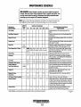
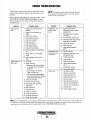
MAINTENANCE SCHEDULE
A WARNING: Never attempt to perform any service while the engine is
running. Wear the proper safety equipment such as goggles and gloves, and
use the correct tools for each job. Disconnect the battery terminals when
servicing any of the engine's DC electrical equipment.
NOTE: Many of the follnwing maintenance procedures are simple but others are
more difficult and may require the expen knowledge of a service mechanic.
CHECK
EACH
DAY
SCHEDULED
MAINTENANCE
Fuel Supply
0
Fuel/Water Separator
0
HOURS OF OPERATION
50
100
250
500
750 1000 1250
EXPLANATION OF SCHEDULED
MAINTENANCE
Unleaded gasoline wrrh octane rating of 89 or
higher.
Check for water and dirt in fuel (drain/replace fitter
if necessary).
Engine Oil Level
0
Oil level should indicate between FULL and LOW on
dipstick.
Coolant Level
0
Check at recovery tank; if empty, check at manifold.
Add coolant if needed.
0
Inspect for proper tension (3/8" to 112" deflection)
and adjust if needed. Check belt edges for wear.
Drive Belt
weekly
0
Visuallnspec!ion of Engine
NOTE: Keep engine surface clean. Dirt and
oil will inhibit the engine's ability to remain
cool.
Spark Plugs
0
0
Generator
Fuel Filter
Carburetor Filler Screen
0
Starting Balleries
(and House Balleries)
0
0
0
0
0
0
0
0
0
0
0
0
0
0
0
0
0
0
0
0
0
0
0
0
0
• Adjust the Valve
Clearances
0
0
0
Air Screen (Flame Arrester)
Exhaust System
0
0
0
0
0
Check that AC connections are clean and secure
with no chafing - see GENERATOR INFORMATION
for addttional information.
Initial change at 50 hrs, then change every 250 hrs.
Inrrial change at 50 hrs, then change every 250 hrs.
Initial engine oil & filter change at 50 hrs., then
change both every 100 hours.
Inttial adjustment at 50 hrs., then every 500 hrs.
0
Clean at 50 hours, then every 100 hours.
0
0
0
0
0
Initial check at 50 hrs., then every 250 hrs. Inspect
for leaks. Check siphon brake operanon. Check the
exhaust elbow for carbon andlor corrosion buildup
on inside passages; clean and replace as necessary.
Check that all connections are tight.
0
Hose should be hard & tight. Replace if soft or
spongy. Check and tighten all hose clamps.
.
Engine Hoses
Check gap; inspect for burning and corrosion.
Every 50 operating hours check electrolyte levels
and make sure connections are very tight. Clean off
excessive corrosion.
weekly
Engine Oil
Check for fuel, oil and water leaks. Inspect wiring
and electrical connections. Keep bolts & nuts tight.
Check for loose belt tension.
0
0
0
0
0
'WESTERBEKE recommends this service be performed by an authorized mechanic.
Engines & Generators
12
(continued)
-+
MAINTENANCE SCHEDULE
NOTE:
Use the engine hounneter gauge to log your engine hours or record your
engine hours by running time.
SCHEDULED
MAINTENANCE
Heat Exchanger
CHECK
EACH
DAY
HOURS OF OPERATION
50
100
250
500
0
0
0
0
Raw Water Pump
0
0
Clean or replace anode. Open heat exchanger end
cap and clean out debris. Remove every 1000 hours
for professional cleaning and pressure testing.
0
Remove pump cover and inspect impeller for wear;
replace if needed. Also replace gasket. Lubricate
both when reassembling.
Drain, flush, and refill cooling system WITh approprtate antifreeze mix.
0
0
EXPLANATION OF SCHEDULED
MAINTENANCE
0
0
'Starter Motor
'Engine Cylinder
Compression and
Valve Clearance
0
0
Coolant System
Distributor
750 1000 1250
0
Check solenoid and motor for corrosion. Remove
and lubricate. Clean and lubricate the Start motor
pinion drtve.
Check ignition timing. Check condition of distributor cap and rotor.
0
0
0
'Engine Timing Belt
0
Incorrect valve clearance will result in poor engine
perfonnance; check compression pressure and timing,
and adjust valve clearances.
Remove and replace every 1000 hours ..
NOTE: Failure to replace the timing belt at the recommended interval could result in timing belt failure resulting in major damage to the engine.
'Exhaust Elbow
Test exhaust elbow for casting integrity. Replace if
casting is corroded or deteriorated.
WARNING: A defecffve exhaust elbow can cause
carbon monoxide leakage!
0
'WESTERBEKE recommends this service be performed by an authorized mechanic.
Engines & Generators
13
COOLING SYSTEM
DESCRIPTION
In other words, the engine is cooled by fresh water coolant,
this coolant is cooled by raw water, and the raw water carries
the transferred heat overboard through the exhaust system.
The fresh water coolant and raw water circuits are independent of each other. Using only fresh water coolant within the
engine allows the cooling water passages to stay clean and
free from harmful deposits.
Westerbeke marine engines are designed and equipped for
fresh water cooling. Heat produced in the engine by combustion and friction is transferred to fresh water coolant which
circulates throughout the engine. This circulating fresh water
coolant cools the engine block, its internal moving parts, and
the engine oil. The heat is transferred externally from the
fresh water coolant to raw water by means of a heat
exchanger, similar in function to an automotive radiator. Raw
water flows through the tubes of the heat exchanger while
fresh water coolant flows around the tubes; engine heat transferred to the fresh water coolant is conducted through the
tube walls to the raw water which is then pumped into the
~~~~system where finally it is discharged overboard.
RAW WATER/COOLANT DIAGRAM
COOLANT
~_-,.;;:;:;;!f"-COOLANT RECOVERY TANK
RAWWATER
c=V
-+
\
\
TO SIPHEN BREAK \
[IF REQUIRED] -,..!..
"
,
\.:,
\.1,\
,
RAW WATER IN
£,j.....'1:
HEAT EXCIHANGER_il
/
RAW WATER D1SI7HARGE"
ZINC
WESTERBEKE recommends this raw wa.
discharge hose be looped above and down to the
exhaust elbow as illustrated.
"tl'Y'
WESTERBEKE
Engines & Generators
14
\
\
\
COOLING SYSTEM
FRESH WATER COOLING CIRCUIT
CHANGING COOLANT
NOTE: Refer to the ENGINE COOLANT section for the
recommended antifreeze and water mixture to be used as the
fresh water coolant.
The engine's coolant must be changed according to the
MAINTENANCE SCHEDULE. If the coolant is allowed to
become contaminated, it can lead to overheating problems.
Fresh water coolant is pumped through the engine by a circulating pump, absorbing heat from the engine. The coolant
then passes through the thermostat into the manifold, to the
A CAUTION: Proper cooling system maintenance is
critical; a substantial number of engine failures can be
traced back to cooling system corrosion.
heat exchanger where it is cooled, and returned to the engine
block via the suction side of the circulating pump.When the
engine is started cold, external coolant flow is prevented by
the closed thermostat (although some coolant flow is
bypassed around the thermostat to prevent the exhaust manifold from overheating). As the engine warms up, the thermostat gradually opens, allowing full flow of the engine's
coolant to flow unrestricted to the external portion of the
cooling system.
Drain the engine coolant by removmg the dram plug on the
engine block and opening the manifold pressure cap. Flush
the system with fresh water, then reinstall the drain and start
the refill process.
NOTE: The drain petcock on the heat exchanger should also
be used to help drain engine coolant.
Coolant Recovery Tank
A WARNING: Beware of the hot engine coolant.
A coolant recovery tank allows for engine coolant expansion
Wear protective gloves.
and contraction during engine operation, without any significant loss of coolant and without introducing air into the cooling system. This tank should be located at or above the
engine manifold level and should be easily accessible.
Refilling the Coolant
After replacing the engine block drain plug, close the heat
exchanger's coolant petcock. Then run the engine at idle and
slowly pour clean, premixed coolant into the manifold.
Monitor the coolant in the manifold and add as needed. Fill
the manifold to the filler neck and install the manifold
pressure cap.
Remove the cap on the coolant recovery tank and fill with
coolant mix to halfway between LOW and MAX and replace
the cap. Run the engine and observe the coolant expansion
flow into the recovery tank.
After checking for leaks, stop the engine and allow it to cool.
Coolant should draw back into the cooling system as the
engine cools down. Add coolant to the recovery tank if
needed and check the coolant in the manifold. Clean up any
spilled coolant.
NOTE: Periodically check the condition of the manifold pressure cap. Ensure that the upper and lower rubber seals are in
good condition and check that the vacuum valve opens and
closes tightly. Carry a spare cap.
TO COOLANT
RECOVERY TANK
FROM COOLANT
• RECOVERY TANK
MANIFOLD
PRESSURE
CAP
COOLANT EXPANSION
SEALS
CHECKING THE PRESSURE CAP
-...v- WESTERBEKE
Engines & Generators
15
COOLANT RETRACTION
COOLING SYSTEM
If the zinc anodes need replacement, hold the hex boss into
THERMOSTAT
which the zinc anode is threaded with a wrench while
loosening the anode with another wrench. This prevents the
hex boss from possibly tearing off the exchanger shell. After
removing the zinc, note the condition of it. If the zinc is in
A thermostat controls the coolant temperature as the coolant
continuously flows through the closed cooling circuit. When
the engine is first started the closed thermostat prevents
coolant from flowing (some coolant is by-passed around the
thermostat to prevent the exhaust manifold from over-heating). As the engine wanns up. the thermostat gradually opens.
The thermostat is accessible and can be checked, cleaned, or
replaced easily. Carry a spare thermostat and gasket.
poor condition, there are probably a10t of zinc flakes within
the exchanger. Remove the end of the heat exchanger and
clean the inside of all zinc debris. Always have a spare heat
Replacing the Thermostat
exchanger end gasket in case the present one becomes
damaged when removing the end cover. Replace the gasket
(refer to your engine model's heat exchanger end gasket part
number), O-ring and cover, and install a new zinc anode.
Remove the cap screws and disassemble the thermostat
NOTE: The threads of the zinc anodes are pipe threads and do
housing as shown. When installing the new thermostat and
not require sealant. Sealant should not be used as it may
insulate the zinc from the metal of the heat exchanger
housing preventing electrolysis action on the zinc.
gasket, apply a thin coat of sealant on both sides of the gas-
ket before pressing it into place. Do not over-tighten the cap
screws.
TO ENGINE BLOCK
Run the engine and check for normal temperatures and that
HEAT EXCHANGER
there are no leaks at the thermostat housing.
FROM RAW WATER PUMP
HEAT EXCliAN(iER);>
'~~?J~-- PRESSURE
"
CAP
THERMOSTAT
ASSEMBLY
COOLANT RECIOVEllY
-;
...
ZINC
ANIOE
{
::.
COOLANT
DRAIN
HEAT EXCHANGER
{/---G.ASKET. APPLY SEALANT
TO BOTH SIDES
WATER
DRAIN
Cool raw water flows through the inner tubes of the heat
exchanger. As the engine coolant passes around these tubes
the heat of the internal engine is conducted to the raw water
which is then pumped into the exhaust system and discharged.
The engine coolant (now cooled) flows back though the
engine and the circuit repeats itself.
The engine coolant and raw water are independent of each
other; this keeps the engine's water passages clean from the
harmful deposits found in raw water.
CLEAN & REUSE
NEW
Heat Exchanger Service
REPLACE
ZINC ANODE
After approximately 1000 hours of operation, remove, clean
A zinc anode (or pencil) is located in the raw water cooling
circuit within the heat exchanger. The purpose of the zinc
and pressure test the engine's heat exchanger. (A local auto·
motive radiator shop should be able to clean and test the heat
anode is to sacrifice itself to electrolysis action taking place
exchanger).
in the raw water cooling circuit, thereby reducing the effects
NOTE: Operating in silty and/or tropical waters may require
of electrolysis on other components of the system. The condition of the zinc anode should be checked monthly and the
anode cleaned or replaced, as required. Spare anodes should
be carried onboard.
that a heat exchanger cleaning be performed more often then
every 1000 hours.
NOTE: Electrolysis is the result of each particular installation and vessel location, not that of the engine.
Engines & Generators
16
COOLING SYSTEM
RAW WATER INTAKE STRAINER
RAW WATER PUMP
NOTE: Always install the strainer at or below the waterline so
The raw water pump is a self-priming, rotary pump with a
non· ferrous housing and a Neoprene impeller. The impeller
has flexible blades which wipe against a curved carn plate
within the impeller housing, producing the pumping action.
On no account should this pump be run dry. There should
always be a spare impeller and impeller cover gasket aboard
(an impeller kit). Raw water pump impeller failures occur
when lubricant (raw water) is not present during engine
operation. Such failures are not warrantable, and operators
are cautioned to make sure raw water flow is present at startup. The raw water pump should be inspected periodically for
broken or torn impeller blades. See MAINTENANCE
SCHEDULE.
the strainer will always be self-priming.
A clean raw water intake strainer is a vital component of the
engine's cooling system. Include a visual inspection of this
strainer when making your periodic engine check. The water
in the glass should be clear.
Perform the following maintenance after every 100 hours of
operation:
1. Close the raw water seacock.
2. Remove and clean the strainer filter.
3. Clean the glass.
s
4. Replace the washer if necessary.
NOTE: Should a failure occur with the pump internal parts
(seals and bearings), it may be more cost efficient to purchase a new pump and rebuild the original pump as a spare.
5. Reassemble and install the strainer.
6. Open the seacock.
7. Run the engine and check for leaks.
Changing the Raw Water Pump Impeller
NOTE: Also follow the above procedure after having run hard
aground.
If the engine temperature gauge ever shows a higher than
Donna1 reading, the cause may be that silt, leaves or grass
may have been caught up in the strainer, slowing the flow of
raw water through the cooling system
Close the raw water intake valve. Remove the pump cover
and, with the aid of two small screwdrivers, carefully pry the
impeller out of the pump. Install the new impeller and gasket.
Move the blades to conform to the curved cam plate and
push the impeller into the pump's housing. When assein~
bling, apply a thin coating of lubricant to the impeller and
gasket. Open the raw water intake valve.
. RAW WATER IN
--_*"
WASHER ->i(;",L;~
STRAINER
I
ALIGN WITH THE
SLOT IN THE SHAFT
t
RAW WATER INTAKE STRAINER
OWNER/BUILDER INSTALLED
TO HEAT
EXCHANGER
A CAUTION: If any of the vanes have broken off the
impeller, they must be .located to prevent blockage in
the COOling circuit. They often can be found in the heat
exchanger.
Engines & Generators
17
FUEL SYSTEM
GASOLINE
Use unleaded 89 octane or higher gasoline. When fueling,
follow U.S. Coast Guard regulations, close off all hatches and
companionways to prevent fumes from entering the boat, and
ventilate after fueling.
A WARNING: Fuel leakage at the fuel pump or its
connections is a fire hazard and should be corrected.
Make sure proper ventilation exists whenever servicing fuel system components.
NOTE: The generator compartment should hove a gasoline fume
detectorlalnrm properly installed and working.
AWARNING: Shut off the fuel valve at the tank
when servicing the fuel system. Take care in catching
any fuel that may spill. DO NOT allow any smoking,
open flames or other sources of fire near the fuel sys·
tem when servicing. Ensure proper ventilation exists
when servicing the fuel system.
LIFT
CARBURETOR
The carburetor is a single barrel downdraft type with a solenoid
activated electric choke and electric fuel shutoff solenoid. Refer
to CARBURETOR ADJUSTMENTS for more information.
CHOKE
GASDENSER
The gasdenser cools the fuel to prevent vapor lock, there is no
maintenance required except making certain the fuel fittings
are tight and secure.
GASOLINE/WATER SEPARATOR AND FILTER
A primary fuel filter of the water separating type must be
installed between the fuel tank and the engine to remove
water and other contaminants from the fuel before they can
be carried to the fuel system on the engine.
Most installers include a type of filter/water separator with
the generator installation package as they are well aware of
the problems that contaminants in the fuel can cause.
IDLE MIXTURE ""._~-J
These gasoline filters must have metal bowls (not "seethrough") to meet U.S. Coast Guard requirements. The metal
bowls have drain valves to use when checking for water and
impurities.
FUEL
SOLENOID
FUEL LIFT PUMP
Periodically check the fuel connections to and out of the pump
and make sure that no leakeage is present and that the fittings
are tight and secure. The DC ground connection at one of the
pump's mounting bolts should be clean and well secured by
the mounting bolt to ensure proper pump operation.
The engine mounted fuel lift pump is maintenance free. It is
located at the front of the engine under the gasdenser.
GASOLINE
WATER SEPERATOR
AND FILTER
OWNER/BUILDER INSTALLED
Engines & Generators
18
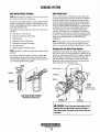
CARBURETOR ADJUSTMENTS
CARBURETOR
Carburetor Filter Screen
The carburetor is a single barrel, down-draft type with a
cleanable metal screen air intake filter/spark arrester.
Clean this filter element after the first 50 hours of operation,
then clean and inspect every 250 operating hours. Replace
the screen if necessary.
Tighten the plug and make certain there are no leaks.
The choke is operated by a 12 VDC solenoid. TIris choke
solenoid is activated when the ON switch is depressed and
stays activated. After the engine starts (cold start) the choke
solenoid circuit is kept activated by the oil temperature
switch. Once oil temperature reaches 120 P the switch opens
and the choke solenoid deactivates, opening the choke. This
helps prevent stalling on a cold start.
Idle Mixture Jet
Adjustment is perfonned with the generator operating. Screw
the jet slowly in until it seats, then back it out 1-112 to 2
turns.
0
Note: An idle mixture jet adjusted too far off its seat can
Air Screen/Flame Arrester
induce a sooty exhaust discharge at engine start-up and
shut-down.
The air screen/flame arrester can easily be removed by
releasing the hold-down clamp. Clean after the first 50 hours
of operation, every 100 hours from then on. Clean the air
screen in kerosene.
AIR SGFtEEII-----""""7<fZ-
TO ROCKER
ARM COVER
AIR INTAKE
FLAME ARRESTER
CHOKE
THROTILE
FROM FUEL
LIFT PUMP
IDLE MIXTURE
In---------f-;:-->1fI.C
CARBURETOR
FILTER SCREEN
FUEL
SOLENOID
HEX HD PLUG
CARBURETOR
~
WESTERBEKE
Engines & Generators
19
ENGINE LUBRICATING OIL
DESCRIPTION
A
WARNING: Used engine oil contains hannful
contaminants. Avoid prolonged skin contact. Clean skin
and nails thoroughly using soap and water. Launder or
discard clothing or rags containing used oil. Discard
used oil properly.
Use a heavy duty engine oil with an API classification of SJ.
Change the engine oil after an initial 50 hours of break-in
operation and every 100 hours of operation thereafter. For
recommended oil viscosity see the following chart:
Operating Temperature
Oil Viscosity
Above 68" F (20" C)
SAE 30, 10W-30 or 15W-40
41" - 68" F (5"-20" C)
SAE 20 or 10W-30
Below 41" F (5" C)
SAE 10W-30
A
Replacing the Oil Filter
When removing the used oil filter, you may find it helpful to
punch a hole in the upper and lower portion of the old filter
to drain the oil into a container before removing it. This helps
to lessen spillage. An automotive filter wrench should be
helpful in removing the old oil filter. Place some paper towels
and a plastic bag around the filter when unscrewing it to catch
any oil that's in the filter. Inspect the old oil filter as it is
removed to make sure that the rubber sealing gasket comes
off with the old oil filter. If this rubber seali.ng gasket remains
CAUTION: 00 not allow two or more brands of
engine oil to mix. Each brand contains its own additives; additives of different brands could react in the
mixture to produce properties harmful to your engine.
sealed against the oil filter adapter, gently remove it. When
installing the new oil filter element, wipe the filter gasket's
CHANGING THE ENGINE OIL
sealing surface on the oil filter adapter free of oil and apply a
thin coat of clean engine oil to the rubber sealing gasket on
the oil filter. Screw the filter onto the threaded oil filter stub,
and tighten the filter firmly by hand.
The engine oil should be warm. Remove the oil drain hose
from its attachment bracket and lower it into a container and
allow the oil to drain, or attach a pump to the end of the drain
hose and pump the old oil out. Make sure the oil drain hose
is properly secured in its holder after all of the old oil has
been drained.
NOTE: Use genuine WESTERBEKE oilfilters. Genericfilters
are not recommended.
Always observe the old oil as it is removed. A yellow/gray
emulsion indicates the presence of water in the oil. Although
this condition is rare, it does require prompt attention to
prevent serious damage. Call a competent mechanic if water
is present in the oil. Raw water present in the oil can
be the result of a fault in the exhaust system attached to the
engine and/or a siphoning through the raw water cooling
circuit into the exhaust, filling into the engine.
REFILLING THE DlL SUMP
Add fresh oil through the valve cover. After refilling the oil,
run the engine for a few moments while checking the engine's
oil pressure. Make sure there is no leakage around the new oil
filter or from the oil drain system, and then stop the engine.
Then check the quantity of oil with the lube oil dipstick. Fill
to, but not over, the FULL mark.
6"
~..o--ll'"
FROM OIL
(;AIII-I<>
NPT
APPLY CLEAN OIL
TO SEALING GASKET
TO OIL GALLERY
FILTER
OIL
HOSE
Engines & Generators
20
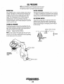
OIL PRESSURE
NOTE: WESTERBEKE recommends that the following engine
adjustments be peifonned by a competent engine mechanic.
The infonnation below is provided to assist the mechanic.
DESCRIPTION
LOW OIL PRESSURE
The lubricating system is a pressure feeding system using an
oil pump. The engine oil is drawn from the oil sump by the
oil pump, which drives the oil, under pressure, through the
oil filter, oil cooler and various lubricating points in the
engine. The oil then returns to the oil sump to repeat the
continuous cycle. When the oil pressure exceeds the
specified pressure, the oil pushes open the relief valve in the
oil pump and returns to the oil sump •. keeping the oil pressure
within its specified range.
The specified safe minimum oil pressure is 4.3 + 1.4 psi (0.3
+ 0.1 kg/cm'). A gradual loss of oil pressure usually indicates
worn bearings. For additional infonnation on low oil pressure
readings, see the ENGINE TROUBLESHOOTING chart.
OIL PRESSURE SWITCH
The generator is fitted with an oil pressure sendor and a
shutdown switch. Should the engine's oil pressure drop
below the safe minimum, the switch will shut the engine
down to prevent damage by interrupting the DC voltage to
the K2 run relay.
TESTING DlL PRESSURE
To test the oil pressure, remove the hex head plug from the
oil manifold and install a mechanical oil pressure gauge in its
place. After warming up the engine, set the engine speed at
1800 rpm and read the oil pressure gauge.
Oil Pressure
NORMALLY OPEN 5 PSI RATED
Between 30 and 40 psi at 1800 rpm.
~~
+
Note: A newly started (cold) engine may have an oil pres-
K2 RELAY
sure up to 70 or 80 psi. A warmed engine can have an oil
pressure as low as 30 psi. Oil pressure will vary depending
on the load placed on the generator:
iBATTERY
....
PRESSURE
MECHANICAL
OIL PRESSURE.
GAUGE
1
\
OIL COOLER
Engines & Generators
21
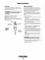
REMOTE OIL FILTER (OPTIONAL)
INSTALLATION
To install, simply remove the engine oil filter and thread on
WESTERBEKE's remote oil filter kit as shown. Always
install this kit with the oil filter facing down as illustrated.
This popular accessory is used to relocate the engine's oil filter from the engine to a more convenient location such as an
engine room bulkhead.
Contact your WESTERBEKE dealer for more information.
NOTE: Refer to ENGINE OIL CHANGE in this manual for
NOTE: Westerbeke is not responsible for engine failure due to
instructions on removing the oilfilter.
incorrect installation of the Remote Oil Filter.
FASTEN SECURELY TO A BULKHEAO
(SCREWS ARE OWNER SUPPlIEO)
• L.
CLEAN OIL TO THE O-RING WHEN
THREAO THE KIT ON. THEN HAND
TIGHTEN AN ADDITIONAl 3/4 TURN AFTER THE O-RING
CONTACTS THE BASE.
n
.............
NOTE THE "IN" AND "OUT" MARKINGS
ON THE ADAPTER WHEN THE HOSES ARE
REMOVED FOR INSTAlLATION SO THEY
WILL BE RECONNECTED CORRECTlY.
APPLY A THIN COAT OF CLEAN OIL TO THE FILTER GASKET WHEN INSTALLING. AmR THE
FIlTER CONTACTS THE BASE, TIGHTEN IT AN
ADDITIONAl 3/4 TURN.
Engines & Generators
22
-- .....
4.5KW /7.0KW BeGB GENERATOR
WIRING DIAGRAM #43864
.
;;
i.16 VIO/WIIT
'14 RH
'=l;;:m ......
416 8Lk
~
'----+-t-----t-H-t-H-t-t---"-'-'''''---*--jll'
tl' R£lHYIO
I
J
I
'---'!.
""
~I
R
"
'-"fN'IWESTERBEKE
I
Engines & Generators
23
/
'".
;;
tit RED/VIO
,!
4.SKW /7 .OKW BeGB GENERATOR
WIRING SCHEMATIC #43864
J
-
12 VDC
r
: BATTERY
, SWITCH
1
1...
STARTER
SOLENOID
1
1
1
1
1
1
.....
r: t-I '20
AMP
(
I CIRCUIT
~I BREAKER
'Kj"Jt1
..."
(
r
•
1
'""I
r
I
I
I
1
I
I
__ ...
BAmu
fUEL PUNP
(HAUER
~
"
..
STOP SW
,
1...
STARTER
r--l
I eKllotC)
I
I
I
I
fUEL SOL.
HOUR METER
COil
"~\,,
,
~
1
L..----- 1
,
I
I
1
1
1
1
o.
f.-wrrc»
L~J
'T~T
,
l
.
..
DIODE
CHOIE SOL.
.
KI~START
IUGOl
L_J
"
CKTZOIO)
;-
EXHAUS~
TEMP ~
SWITCH
I
11$412 0100£
n
SW~CH
;-
DlsnlBUTOR
~
-
K2-RUM
OV£ISPEEll
"
'liDS.
0" \....,~ ,...
$WI reH
nl
."'TER
~
TOO
~~
SWITCHit
I
'''"
K,
,
n
DIODE
"
••
"
JUGOZ
"
~
A~L
PlUs. SWITCH
.o..'"'-L
, -- , _r'L~ • _.12L [~:L ~ fi!I
I!_-.ll !L._
"'" WESTERBEKE
Engines & Generators
24
13
_t~
~
REMOTE PANEL WIRING
SCHEMATIC #043912
REMOTE PANEL
RED
RED
CKT I ' - - - - - - - t - - - i \ ' I
ON SW
WHITE
WHITE
*14 RED/VIO
VIEWED FROM
MATING END
Engines & Generators
25
ENGINE ADJUSTMENTS
NOTE: WESTERBEKE recommends that the following
engine adjustments be peifonned by a competent engine
mechanic. The information below is provided to assist the
mechanic.
ENGINE SPEED (HERTZ) ADJUSTMENT
Governor Maintenance
Governor
1. Periodically lubricate the linkage arm attaching points at
the governor arm and throttle lever. Use a graphite
lubricant or equivalent.
The belt-driven, mechanically operated governor maintains
the engine's rpm under various load conditions. Engine speed
determines the hertz and voltage output of the generator.
NOTE: Free movement of this linkage arm is imponantfor
proper governor/throttle operation.
Governor Adjusbnents
Operate the generator to bring the unit up to operating temperature before adjusting the governor.
2. Governor oil capacity -
3 ounces 10/30 engine oiL
NOTE: lfthe governor is severely out of adjustment, manually
3, Change the governor oil every 250 hours of operation.
NOTE: Do not overfill the governor.
adjust the linkage at no-load to obtain a safe output voltage
before proceeding with the adjustment.
To change the oil, remove the governor from the engine,
remove the oil fill and the fill level plug, and drain all the
oil. Reinstall on the engine and fill with 3 ounces of 10/30
engine oil. Replace the plugs.
There are three adjusting points on the governor (see illustration).
1. IncreaselDecrease Speed Adjustment. This adjusting bolt
sets the no-load speed of the engine. (The linkage arm
between the governor arm and throttle lever should be
adjusted to hold the throttle full open when the engine is
not running.) Make sure this linkage moves freely and
that the ball joint connectors are properly lubricated. Use
graphite lube for this purpose. Disconnect the ball joint
and apply graphite lube to the inside of the joint.
4, Periodically adjust the governor belt tension (see DRIVE
BELTS ADJUSTMENT). Since belts stretch slightly, this
stretching will, to some degree, affect the gavenor's
action.
TORQUING THE CYLINDER HEAD BOLTS
After the initial break-in period (approximately 50 hours). the
cylinder head bolts should be re-torqued.
2. Hunting/Regulation Adjustment. If the variation in
engine speed between no-load and full-load is too great,
adjust this eye bolt to draw the spring closer to the lever
hub. The increase/decrease speed bolt may need to be
adjusted as well.
Tighten the cylinde:r head bolts according to the sequence
shown. Make sure the engine is cold when this is done, and
loosen one head bolt one-half turn and then tighten it
between 43 - 51 lb-ft (60 - 70 Nm). Then proceed to the next
head bolt in the sequence. Tighten the RS (rocker cover stud)
securely.
If the governor surges under load, adjust this eye bolt to
move the spring away from the lever hub (check speed
adjustment).
6
2
4
7
INTAKE SIDE
3. Bumper Screw Adjustment. This screw is used to remove
a no-load surge ONLY. NEVER turn the bumper screw
into the governor so far that it increases the no-load speed.
FRONT OF...-..-.,
ENGINE ~
GOVERNOR
LINKAGE
FILL
BUMPER SCREW
LEVER
8
HUNTING
ADJUSTMENT
SPEED ADJUSTMENT
(UNDER)
Engines & Generators
26
1
5
ENGINE ADJUSTMENTS
SPARK PLUGS
DRIVE BELT ADJUSTMENT
The spark plugs should be cleaned and regapped after the
fIrst 50 hour break-in period, then inspected every 250 hours
thereafter and replaced as needed.
The drive belt must be properly tensioned. Excessive drive
belt tension can cause rapid wear of the belt and reduce the
service life of the fresh water pump's bearing. A slack belt or
the presence of oil on the belt can cause belt slipping,
resulting in high operating temperatures.
A WARNING: 00 not remove the spark plugs while
The BCGB generator has two drive belts, one drives the
the engine is hot. Allow the engine to cool before
removing them.
governor and alternator and the other drives the raw water
pump. The tension adjustment procedure for both belts is as
follows:
Spark plug gap: 0.031 +/_ 0.0002 in. (0.8 - 0.05 mm).
1. Remove the belt guard.
Spark plug torque: 10 -15 Ib-tt (1.5 - 2.31 kg-m).
2. To adjust the governor drive belt, loosen the two governor
mounting bolts.
NOTE: Loctite Anti-Seize applied to the threaded portion of
To adjust the raw water pump/fresh water pump drive
belt, loosen the two raw water pump mounting bolts.
the spark plugs will retard corrosion, making future removal
of the spark plugs easier.
3. With the belt(s) loose, inspect for wear, cracks and frayed
edges, and rep1ace if necessary.
GAP
INSPECT FOR
WEAR & r",MJ"/
INSPECT FOR
DAMAGE
4. To loosen or tighten the governor drive belt, slide the
governor in or out as required, then retighten its mounting
bolts.
To loosen or tighten the raw water pump/fresh water
pump drive belt, slide the raw water pump in or out as
required, then retighten its mounting bolts.
INSPECTING
THE SPARK
PLUGS
~:::t"-----NJ<rVFOR
DETERIORATION
AND DAMAGE
5. The drive belts are properly adjusted if it can be deflected
no less than 3/8 inch (1Omm) and no more than 112 inch
(12mm) as the belt is depressed with the thumb at the
midpoint between the two pulleys on the longest span of
the belt.
NOTE: Maintain a 22 lb pressure to the belt's outer face
for proper belt operation. Spare belts should always be
carried on board
A WARNING: Never attempt to check or adjust a
drive belt's tension while the engine is in operation.
6. Operate the generator for aboUl 5 minutes, then shut down
the generator and recheck the belt(s) tension.
7. Replace the belt guard.
Engines & Generators
27
ENGINE ADJUSTMENTS
NOTE: WESTERBEKE recommends that the following engine
adjustments be peiformed by a competent engine mechanic.
The injonnation below is provided to assist the mechanic.
VALVE CLEARANCE ADJUSTMENT
IGNITION TIMING
NOTE: Retorque the cylinder head bolts before adjusting the
1. Attach a timing light to the #1 spark plug and mark the
front timing pointer to indicate 1'5°. Locate the timing
mark on the crankshaft pulley and mark it with white
chalk or a crayon.
engine~
valves (see TORQUING THE CYLINDER HEAD
BOLTS).
1. Remove the rocker cover and gasket.
2. Rotate the crankshaft in the normal direction of rotation,
2. Start the engine and warm it up to its normal operating
temperature. Make sure the generator is operating without
a load on it.
placing the No. I piston at the top of its compression
stroke with the exhaust and intake valves completely
closed. Adjust the intake and exhaust valves for No. I
cylinder, the exhaust valve for No.2 cylinder, and the
intake valve for No.3 cylinder (see chart).
3. Using the timing light, align the timing mark in the front
crankshaft pulley so it is just slightly before the first timing pointer. Do this by loosening and slowly rotating the
distributor body. Use the following timing specifications:
3. Rotate the crankshaft 1800 in its normal direction of
rotation. Locate the piston in No. I cylinder at the top of
its exhaust stroke. Adjust the intake valve for No.2
cylinder and the exhaust valve for No.3 cylinder (see
chart).
Timing Specifications: 1:f
(no load on generalor)
±
.5° BTDC at 1800 rpm
. IGNITION TIMING
CYLINDER #
CRANK ANGLE
1
When No. 1 piston is set at top of
compression stroke
When No. 1 piston is positioned
at top of exhaust stroke
IN
EX
IN
EX
2
3
•• • •
•
•
4.. Replace the rocker cover along with a new rocker cover
gasket..
CHOKE SOLENOID
Rockercover torque: 2.9-5.1 Ib-ft (4 - 7 Nm)
The choke solenoid is a 12 volt DC operated unit that functions to close the choke plate in the carburetor when the ON
switch is depressed during engine start-up.
The choke solenoid de-energises once the engine starts and
the ON switch is released. Some unstable running may be
present when the engine starts cold but should smooth out as
the engine reaches operating temperature.
Keep this solenoid dry and periodically lubricate the linkage
between the solenoid and the choke lever.
VALVE
CLEARANCE
Valve Clearance:
Intake
Exhaust
0.20mm (.008 inches)
0.30mm (.0012 inches)
CHOKE
SOLENOID
-...v'
WESTERBEKE
Engines & Generators
28
ENGINE ADJUSTMENTS
NOTE: WESTERBEKE recommends that the following engine
adjustments be peiformed by a competent engine mechanic.
The infonnation below is provided to assist the mechanic.
TIMING BELT INSPECTION AND REPLACEMENT
5. Remove the timing belt.
NOTE: If the timing belt is to be reused, draw an arrow on
the belt back to indicate the direction of rotation (clockwise).
Timing Belt Removal
A CAUTION: Water Dr oil on the timing belt severely
reduces the service life of the belt. Keep the timing
belt sprocket and tellSioner free of oil and grease.
7bese parts should never be cleaned. Replace if seriously contaminated with dirt Dr oil. If oil is evident on
these parts, check tbe front case, oil pump oil seals,
and camshaft oil seals for a possible oil leak.
1. Turn the crankshaft clockwise to align-the timing mark on
the camshaft sprocket and timing belt rear cover.
Camshaft Sprocket Removal
NOTE: always tum the crankshaft clockwise.
1. Remove the bolt without turning the camshaft.
TIMING
MARK
2. Remove the plug on the left surface of the cylinder block
and insert a rod with a diameter of 8mm (0.3lin.) to lock
the counterbalance shaft.
NOTE: Be sure to use an inserting rod with a diameter of
8mm (0.31 in.).
2.6 IN (65MM) --:J~~~*:::::1
ROO
Oil Pump Sprocket Flange Nut Removal.
1. Remove the plug from the left side of the cylinder block.
CYLINDER
BLOCK
2. Insert an 8 mm (0.31 in.) diameter round bar to lock the
counterbalance shaft.
3. Loosen the timing belt tensioner nut.
3. Remove the nut.
4. Move the timing belt tensioner toward the water pump,
and temporarily tighten the nut to hold the tensioner in
that position.
TIMING BELT TENSIONER
PUMP
OIL PUMP SPROCKET
Engines & Generators
29
NUT
ENGINE ADJUSTMENTS
NOTE: WESTERBEKE recommends that the following engine
adjustments be performed by a competent engine mechanic.
The information below is provided to assist the mechanic.
Crankshaft Bolt Removal
Flange Installation
1. Lock the crankshaft in position.
1. Mount the flange so that its side shown by the heavy
arrow in the illustration faces toward the sprocket.
NOTE: Do not tum the crankshaft.
FLANGE
2. Remove the crankshaft bolt.
WASHER
-~-rrnmniP
Timing Belt Inspection
Replace the belt if any of the following conditions exist:
1. Hardening of back rubber-back side is glossy, without
resilience, and leaves no indent when pressed with finCRANKSHAFT
gernail.
2. Cracks on rubber back.
Crankshaft Bolt Installation
3. Cracks or peeling of canvas.
1. Lock the crank.Shaft.
4. Cracks on tooth bottom.
NOTE: Do not tum the crankshaft.
S. Cracks on belt.
2. Tighten the crankshaft bolt to the specified torque.
6. Abnormal wear of belt sides. The sides are normal if
they are sharp as if cut by a knife.
Oil Pump Sprocket Flange Nut Installation
7. Abnormal wear on teeth.
1. Insert a round bar into the plug hole in the left side of the
8. Tooth missing and canvas fiber exposed.
cylinder block to keep the counterbalance shaft from turning.
~:
Ii
2. Install the oil pump sprocket.
3. Tighten the nut to the specified torque.
1.
2.
CRACKS OR
PEELING
4"'IROlINDI:O
/
EDGE
AIIN(jR.MAL WEAR
IItL'''tT STRANO)
NUT
'OIL PUMP
SPROCKET
Camshaft Sprocket Bolt Installation
5.
6.
7.
1. Tighten the bolt to the specified torque.
TOOTH MISSING
AND CANVAS
EXPOSED
RUBBER
EXPOSED-.-~~~
Bearing Cap Bolt Torque 36 40 HJbs (50 ·55 Nm)
8.
Tensioner Inspection
1. Replace the tensioner if the pulley binds, rattles or is noisy
when turned.
~
WESTERBEKE
Engines & Generators
30
BOLT
ENGINE ADJUSTMENTS
NOTE: WESTERBEKE recommends that the following engine
adjustments be performed by a competent engine mechanic.
The injonnation below is provided to assist the mechanic.
Tensioner Spring/Timing Tensioner Installation
At this time, check that the moveable range of teeth on
the oil pump sprocket is according to specifications.
1. Install the tensioner spring and timing belt tensioner.
Standard value: 4 to 5 teeth in forward direction.
1 to 2 teeth in reverse direction.
2. Hook the tensioner spring onto the bend of the timing belt
tensioner bracket and the stopper pin on the cylinder
block.
3. Move the timing belt tensioner as close as possible to the
water pump; temporarily tighten the tensioner nut.
TIMING BELT
TENSIONER
FORWARD
\
Oil PUMP
SPROCKET
REVERSE
4. If the movable range of the oil pump sprocket exceeds
the specified range, correct as follows:
a. Pull out the round bar from the plug hole in the left
side of the cylinder block.
b. Turn the oil pump sprOCket one turn at a time until
the round bar can again be inserted.
Timing Belt Installation
c. Check that the movable range of the oil pump
sprocket is in the specified value.
1. Align the trIangular marking on the camshaft sprocket
with a marking on the timing belt rear cover.
5. Set the timing belt over the crankshaft sprocket and
then over the oil pump sprocket and camshaft sprocket,
in that order.
2. Align the notch in the crankshaft sprocket flange with
the marking on the front case.
NOTE: Ensure that the tension side of the timing belt is
not slack. Keep the round bar inserted until the timing
belt has been placed. After this step, be sure to remove
the round bar.
3. Align the triangular marking on the oil pump sprocket
with the marking on the front case, and then insert a 65
mm (2.56 in.) or longer, 8 mm (0.31 in.) diameter
round bar into the plug hole in the left side of the
cylinder block.
6. Apply counterclockwise force to the camshaft sprocket
to make the belt taut on the tension side, and make
sure that all timing marks are lined up.
~;;;';;;;;;'3~~-,
MARKING ON
TIMING BELT
REAR COVER
TRIANGULAR MARKING
ON Oil PUMP SPROCKET
CAMSHAFT
SPROCKET
TENSION SIDE
TIMING BELT
TENSIONER
7. Loosen the temperorarily tightened tensioner nut On
the water pump side 1 or 2 turns, and tension the belt
making use of spring force.
TRIANGULAR
MARKING ON
"_O:~;;"<~L CAMSHAFT
SPROCKET
NOTCH IN
CRANKSHAFT
SPROCKET
FLANGE
MARKING
ON FRONT
CASE
1':,.y-=:tWESTERBEKE
Engines & Generators
31
ENGINE ADJUSTMENTS
NOTE: WESTERBEKE recommends that the following engine
adjustments be peiformed by a competent engine mechanic.
The information below is provided to assist the mechanic.
8. Tum the crankshaft clockwise by nine camshaft sprocket
teeth (817) to align the timing mark on the camshaft
sprocket with the tensioner set mark on the timing belt
ENGINE COMPRESSION TEST
1. To check the engine's compression pressure, warm up the
engine then shut it down.
rear cover.
A
2. Remove the three spark plug caps and remove the three
spark plugs.
CAUTION:
This operation is performed to give a
proper tension to the timing belt, so do not turn the
crankshaft counterclockwise and push the belt to
check the tension.
3. Install a compression adapter and gauge in the spark plug
hole.
4. Close off the raw water intake seacock.
5. Crank the engine with the start motor and unplug the
ignition coil and allow the compression gauge to reach a
maximum reading and record.
:::;;;;~;;;;::;;:::- .:n;.~- TENSIONER
SET MARK
6. Measure the compression pressure for all the cylinders .
Ensure that compression pressure differential for each
cylinder is within the specified unit.
Compression pressure should not differ by more than 14 psi (100 Kpa).
7. If a cylinder's compression or pressure differential is
below the limit, add a small amount of engine oil through
the spark plug hole and repeat steps 4 and 5.
9. Make sure that the timing belt teeth are engaged with
the camshaft sprocket teeth along the portion of the
sprocket shown by the curved arrow in the illustration
below. Then tighten the tensioner nut.
(a) If additional of oil causes an increase of pressure, the
piston ring and/or cylinder wan may be worn or damaged.
(b) If additional oil does not increase compression pressure suspect poor valve contact, valve seizure, or valve
wear.
10. Pull the timing belt in the center of the tension side
toward the sealing gasket line for the belt cover, as
illustrated. Make sure that the clearance between the
back of the belt and the sealing line is the standard
value.
S. Reinstall three plugs and ignition wires.
9. Open the raw water thm seacock.
Standard Value: 12mm (0.47in.)
SEALING
LINE
COMPRESSION
GAUGE
(TYPICAL)
"'if---1:!MM (0.47 IN)
11. Pull out a rod from the plug hole on the left surface of
the cylinder block and apply the specified sealant.
Then tighten the plug to the specified torque.
Specified sealant value: 3M AID Part No. 8660 or
equivalent
Tightening torque: 15-22 Nm (11-16 ft.lbs.)
""'" WESTERBEKE
Engines & Generators
32
COMPONENT TESTING
NOTE: WESTERBEKE recommends that the following engine
testing adjustments be perjonned by a competent technician.
GENERAL
All DC voltage measurements are made to the engine battery
negative ground point unless specified otherwise. In making
test measurements, make sure that a good ground for the
meter is established, preferably the point where the negative
battery is connected to the engine. Battery positive voltage is
indicated as B+ and should measure no less than JI.5 volts.
TAP THE GROUND
CONNECTION TO
THE TERMINAL
RELAY SHOULD
~o~o "CLICK" ON.
o
_ _ _
AC voltage measurements should be made with a true
RMS AC meter to insure measurement accuracy.
TO B(+)
TESTING THE RELAY
TERMINALS
GROUND AND 8(+)
CONNECTIONS
---.•",.
RELAYS
The relays used in the control system have coils which are
polarized by the fact that they have internal free wheeling
suppression diodes across them. Relay coil terminal 86 must
be maintained (+), terminal 85(-). The relay coil is rated 12V
DC, and the coil resistance is typically 85 ohms. With B+ on
tenninal 86, direct grounding of tenninal 85 is pennissible
TESTING COIL RESISTANCE
for testing purposes.
RELAYS
RELAY
TERMINALS
REMOVE THIS
RELAY CONNECTOR
~
WESTERBEKE
Engines & Generators
33
ENGINE TROUBLESHOOTING
The following troubleshooting tables are based upon certain
engine problem indicators and the most likely causes of the
problems.
NOTE: The engines control system (electrical system) is
protected by a 20 Ampere manual reset circuit breaker
located on the control panel.
When troubleshooting indicates an electrical problem, see the
ELECTRICAL SYSTEM WIRING DIAGRAM, as these
may reveal other possible causes of the problem which are
not listed below.
Engine does not
crank.
Engine cranks but
fails to start.
PROBLEM
PROBABLE CAUSE
PROBLEM
1. Voltage drop at starter solenoid
terminal.
2. Engine 20A circuit breaker has
tripped.
3. Battery is low or dead.
4. Loose battery connections.
5. Faulty wire connection.
6. Faulty start switch.
7. Faulty start relay (K1).
S. Faulty starter solenoid
9. Raw water filled cylinders.
10. Filters are clogged by contaminated
fuel.
11. Voltage drop at (+) at overspeed
switch.
12. Faulty overspeed switch (reset &
start).
Engine starts, runs
and then shuts
down.
6.
7.
S.
9.
10.
11.
1. Faulty shutdown switch,
2.
3.
4.
5.
6.
7.
Engine starts, runs
but does not come
up to speed.
(oil pressure, water or exhaust
temperature) .
High engine water or exhaust
temperature.
Dirty fuel/water separator filter.
Mechanical check valve at the fuel
supply faulty. (If installed).
Low oil level in sump.
Faulty fuel pump.
Faulty engine temperature
sensor.
1. Fuel line restriction.
2. Mechanical check valve at the
fuel supply is faulty.
3. Throttle plate binding.
4. Faulty fuel pump.
5. Faulty wire connection.
6. Faulty engine temperature
1. Out of fuel.
2. Engine is flooded.
3.
4.
5.
PROBABLE CAUSE
a. Carburetor float needle valve open
or damaged. Clean or replace the
needle valve.
b. Float in carburetor is leaking.
Repair or replace float.
c. Float chamber gasket damaged or
securing screws are loose. Replace
gasket and/or tighten screws.
Fuel pump inoperative.
Worn or faulty spark plugs.
High tension wires grounding
(wet system).
Faulty ignition coil.
Faulty distributor.
Faulty run relay (K2).
Faulty wire connection.
No engine compression.
Faulty idle adjustment.
Engine hunts.
7.
S.
1.
2.
3.
4.
5.
6.
7.
S.
9.
10.
sensor.
AC generator overload.
HiQh exhaust pressure.
Low battery voltage.
Generator is overloaded.
Cracked distributor cap.
Faulty high tension wires.
Faulty fuel pump.
High exhaust back-pressure.
Valves are out of adjustment.
Governor is out of adjustment.
Dirty fuel filters.
Throttle linkage is binding.
NOTE: When troubleshooting a loss of ignition spark and the overspeed switch is suspect: By-pass the switch by lifting the
T3 connector (overspeed terminal board) and connecting it to the vacant T4 spade connector. Start the engine and if the
spark returns, the overspeed switch is at fault. Refer to the OVERSPEED WIRING DIAGRAM.
.....v'
WESTERBEKE
Engines & Generators
34
ENGINE TROUBLESHOOTING
PROBLEM
Engine misfires.
PROBABLE CAUSE
PROBLEM
No DC charge to the
starting battery.
1. Poor quality fuel.
2.
3.
4.
5.
6.
Incorrect timing.
Dirty flame arrester.
Cracked distributor cap.
Faulty ignition wires.
Spark plugs are worn.
7. High exhaust back-pressure.
8. Valve clearances are incorrect.
Engine backfires.
Blue exhaust smoke
1. Lube oil is diluted.
discharge from the
engine.
2. High lube oil level.
3. Crankcase breather hose is clogged.
4. Valves are worn or adjusted
wrong.
incorrectly.
5. Piston rings are worn
or unseated.
flooded under Engine cranks but
tails to start.
4. Dirty flame arrester.
5. Cracked distributor cap.
6. High exhaust back-pressure.
Low oil pressure.
Black exhaust smoke
discharge from the
engine.
1. Dirty flame arrester.
2. Faulty carburetor.
3. Idle mixture jet too rich.
4. Accelerator diaphram leaking.
1. Coolant loss. Pressure test
5. Valves are worn or incorrectly
cooling system.
Faulty raw water pump impeller.
Belts are loose or broken.
Raw water pump worn.
Faulty thermostat.
adjusted.
6. Lube oil is diluted.
7. Piston rings are worn or unseated.
8. Crankcase breather hose is clogged.
1. Low oil level.
2.
3.
4.
5.
6.
Poor performance
at generator speed.
Wrong SAE type oil in the engine.
Wrong type oil filter.
Relief valve is stuck.
Faulty oil pump.
Faulty engine bearings.
1. Main jet clogged. Remove and clean.
2. Carburetor inlet filter clogged.
Remove and clean.
3. Fuel pump clogged. Remove and
replace.
4. Air intake filter screen dirty. Remove
and clean.
7. Faulty oil filter.
High oil pressure.
battery charging control.
windings.
1. Spark plug wires are connected
2.
3.
4.
5.
1. Faulty connections to
2. Faulty battery charging control.
3. Faulty bridge rectifier.
4. Faulty generator charger
2. Incorrect timing.
3. Engine is flooded. See Engine is
Engine overheats.
PROBABLE CAUSE
1. Dirty oil or wrong SAE type oil in the
engine.
2. Relief valve is stuck.
Engines & Generators
35
GENERATOR INFORMATION
USE OF ELECTRIC MOTORS
Generator Frequency Adjustment
The power required to start an electric motor is considerably
more than is required to keep it running after it is started.
Some motors require much more current to start them than
others. Split-phase (AC) motors require more current to start,
under similar circumstances, than other types. They are
commonly used on easy-starting loads, such as washing
machines, or where loads are applied after the motor is
started, such as small power tools. Because they require 5 to
7 times as much current to start as to run, their use should be
avoided, whenever possible, if the electric motor is to be driven by a small generator. Capacitor and repulsion-induction
motors require from 2 to 4 times as much current to start as
to run. The current required to start any motor varies with the
load connected to it. An electric motor connected to an air
compressor, for example, will require more current than a
motor to which no load is connected.
In general, the current required to start 115-Volt motors connected to medium starting loads will be approximately as
follows:
Frequency is a direct result of engine/generator speed, as
indicated by the following:
• When the generator is run at 1800 rpm, the AC voltage
output frequency is 60 Hertz.
• When the generator is run at 1500 rpm, the AC voltage
output frequency is 50 Hertz.
Therefore, to change the generator's frequency, the generator's drive engine's speed must be changed. Along with a
reconfiguring of the AC output connections at the generator,
a regulator board voltage output adjustment must also be
made. See ELECTRONIC GOVERNOR in this manual.
MOTOR SIZE
(HP)
1/6
1/4
1/3
1/2
3/4
1
AMPS FOR
RUNNING
(AMPERES)
3.2
4.6
5.2
7.2
10.2
13
Generator Maintenance
• Maintaining reasonable cleanliness is important.
Connections of terminal boards and rectifiers may become
corroded, and insulation surfaces may start conducting if
salts, dust, engine exhaust, carbon, etc. are allowed to
build up. Clogged ventilation openings may cause excessive heating and reduced life of windings.
• For unusually severe conditions, thin rust-inhibiting
petroleum-base coatings, should be sprayed or brushed
over all surfaces to reduce rusting and corrosion.
• In addition to periodic cleaning, the generator should be
inspected for tightness of all connections, evidence of
overheated terminals and loose or damaged wires.
• The drive discs on single bearing generators should be
checked periodically if possible for tightness of screws
and for any evidence of incipient cracking failure. Discs
should not be allowed to become rusty because rust may
accelerate cracking. The bolts which fasten the drive disc
to the generator shaft must be hardened steel SAE grade
8, identified by 6 radial marks, one at each of the 6 corners of the head.
AMPS FOR
STARTING
(AMPERES)
6.4 to 22.4'
9.2 to 32.2'
10.4 to 72.S'
14.4 to 29.2'
20.4 to 40.S'
26 to 52
'NOTE: In the above table the maximum Amps for Starting is
more for some small motors than for larger ones. The reason
for this is that the hardest starting types (split-phase) are not
made in larger sizes.
Because the heavy surge of current needed for starting
motors is required for only an instant, the generator will not
be damaged if it can bring the motor up to speed in a few
seconds. If difficulty is experienced in starting motors, turn
off all other electrical loads and, if possible, reduce the load
on the electric motor.
• The rear armature bearing is lubricated and sealed; no
maintenance is required. However, if the bearing becomes
noisy or rough-sounding, have it replaced.
• Examine bearing at periodic intervals. No side movement
of shaft should be detected when force is applied. if side
motion is detectable, bearings are wearing or wear on
shaft of bearing socket outside bearing has occurred.
Repair must be made quickly or major components will
rub and cause major damage to generator.
Required Operating Speed
Run the generator first with no load applied, then at half the
generator's capacity, and finally loaded to its full capacity as
indicted on the generator's data plate. The output voltage
should be checked periodically to ensure proper operation of
the generating plant and the appliances it supplies. If an AC
voltmeter or ampmeter is not installed to monitor voltage and
load, check it with a portable meter and ampprobe.
Carbon Monoxide Detector
WES1ERBEKE recommends mounting a carbon
monoxide detector in the vessels living quarters. Carbon
monoxide, even in small amounts is deadly.
The presence of carbon monoxide indicates an exhaust
leak from the engine or generator, from the exhaust
elbow/exhaust hose, or that fumes from a nearby vessel
are entering your boat.
If carbon monoxide is present ventilate the area with clean
air and correct the problem immediately!
NOTE: When the vessel in which the generator is installed
contains AC equipment of 120 volts only, it is recommended
that the generator's AC terminal block be configured to provide one 120 volt AC hat leg for the vessel's distribution
panel. This will ensure good motor starting response from the
generator.
Engines & Generators
36
Be GENERATOR SINGLE PHASE
NOTE: WESTERBEKE recommends that the following generator tests
and adjustments be peiformed by a qualified technician.
DESCRIPTION
Circuit Breaker
The Be generator is a brushless, self-excited generator which
requires only the driving force of the engine to produce an
AC output. The stator houses t:'IXro setS of windings; the main
stator windings and the exciter windings. When the generator
is started, residual magnetism in the four rotating poles
induces a voltage in the stator which then generates an even
larger voltage in the exciter windings. This mutual build up
of voltage in the four rotating poles and in the exciter windings quickly reaches the saturation point of the capacitor(s)
and a regulated energy field is then maintained in the stator.
At the same time, this regulated field produces a steady voltage in the stator windings which can then be drawn off the
generator's AC terminals to operate AC equipment. The
generator is a single-phase, reconnectable 120 volt AC twowire or 240 volt AC three-wire, at 60 hertz; or 115 volt AC
two-wire or 230 volt AC two-wire, at 50 hertz. Refer to the
SPECIFICATIONS section of this manual for generator ratings. The generator's data plate gives the voltage, current and
frequency rating of the generator. An AC wiring decal is
affixed to the inside of the louvered cover at the generator
end. A diagnlIl1 of the various AC voltage connections is provided on the decal. An Integral Controller (IC) is mounted
inside the generator and supplies a continuous DC charge to
the generators starting battery when the generator is running.
For more information see the INTEGRAL CONTROLLER
DC CHARGER section in this manual.
A circuit breaker is installed on all single phase
\VESTERBEKE generators. This circuit breaker will automatically disconnect generator power in case of an electrical
overload. The circuit breaker can be manually shut off when
servicing the generator to ensure that no power is corning
into the boat.
NOTE: This circuit breaker is available as a WESTERBEKE
add-on kit for earlier model generators; contact your
WESTERBEKE dealer.
Circuit Breaker Part Numbers
7.0Kw
S.8Kw
4.5Kw
3.8Kw
#042714
#042713
#042232
#042712
r-----------------------------------------,:
MODEL 4.5 : D
GENERATOR INTERNAL WIRING
SCHEMATIC WITH DC BATTERY
CHARGING CIRCUIT
q lfj------:-:-----------------ffI 6
L------j:1 n!
i
ifr----:
:
::
:;
!DiOD~ i 6::;
[
in m11Q
,,
''
I
:
r---------,I II
I
:
-
I
I I
I
I
!
I
II
!
CEXCITER WINDINGS AND CAPACITDR(S).
DIODE.
B I D DC BAmRY CHARGING CIRCUIT WITH
I
I:
IA
::
2
!
j
1
11
411
1010DE
II,
I
]
I
1
I
A ROTATING FIELD/AUXILIARY WINDINGS
WITH DIODES.
B MAiN STATOR WINDINGS.
II
~
i
~
I
BRIDGE RECTIFIER AND INTEGRAL
CONTROLLER.
I
MODEL 7.0
~I
I I
t- I
5"
I
J
I I
6 I
I ~ ______ - - ____ ...I
1 98
1
H600
Lc:i~I~~_
r"D-- 30AMP---------------------------------l
I
I
I
I
"
r---------,I I,
I
INTEGRAL
CONTROLLER
I
:I
DIDDq
r
II
I,
Bl
-----------
~l
2=:,
iA::
1IIf--------~L-----:
L ________ J
50i:
6050
I"
9898
ic t "PAI~
6
II..
III
t "PAI~
I
:
_ _ _ _ _ _ _ _ _ _ _ _ _ _ _ _ .J
DUAl EXCITER CIRCUIT
Engines & Generators
37
I
:
J
Be GENERATOR SINGLE PHASE
NOTE: WESTERBEKE recommends that the following generator tests
and
be peiformed by a qualified technician.
GROUND
SINGLE EXCITER CIRCUIT
BRIDGE
60Hz 120 VOLT CONFIGURATION ILLUSTRATION
CAPACITOR/
WHITE
NOTE: THE #7 WIRE IS
SHOWN CONNECTED AS
A DEMONSTRATION OF
HOW THESE CONNECTIONSCAN
BE MADE.
,
-<b"-INTEGRAL CONTROLLER
//
[BATTERY CHARGERI
TERMINAL BOARD
SINGLE EXCITER NO-LOAD VOLTAGE ADJUSTMENT
1. Remove the louvered metal plate, at the back of the
generator, covering the AC terminal connections and
the capacitor(s).
2. Start the generator and allow it to run for approximately
five minutes so the engine can wann up. Make Sure the
generator is operating without any equipment drawing AC
current from the generator (that is, shut off all electrical
appliances). Make sure the engine's speed (Hertz) is
correct. Adjust the governor as needed to obtain the
correct engine speed before proceeding.
3. Refer to the AC LOAD CONNECTIONS DIAGRAM for
the correct configuration then check the generator's
no-load voltage by measuring the voltage across the neutrallead and the hot lead with a volt meter. Make sure you
record this reading. The generator's no-load voltage is
115 - 124 volts at 60.5 - 61.5 Hertz. If the voltage output
is higher or lower than specified, proceed.
4. Shut off the generator. Make sure the correct Hertz lead
(60 Hertz #6, or 50 Hertz #5) is plugged into the
capacitor(s).
II
lz
A WARNING: 00 not attempt to make a no-load
voltage adjustment while the generator is operating.
The capacitor can produce a 400-500 volt charge.
Touching any wiring can produce a severe electrical
shock. In addition, attempting to make a no-load voltage adjustment while the generator is operating could
cause your fingers to be caught in the generator's rotor.
5. There are three plugs grouped for the capacitor
tenninal, #7, #8, and #9. If the generator's no-load voltage
is low, then disconnect the lower numbered plug and connect the plug with the next higher number. If the generator's no-load voltage is high, then disconnect the higher
numbered plug and connect the plug with the next lower
number. Note that the plug presently connected to this
terminal may be anyone of the three plugs available.
6. If the generator's no-load voltage cannot be adjusted
because the voltage needs to be increased and the highest
numbered plug is already connected to the right tenninal,
or the voltage needs to be lowered and the lowest numbered plug is connected, refer to the WESTERBEKE BC
Generator Troubleshooting Guide),
A WARNING: Capacitors must be discharged before
handling as they store electricity and can pack a potentially lethal charge even when disconnected from their
power source.
NOTE: Simply cross the capacitor's two terminals with an
insulated (plastic handle) screwdriver. This will discharge
any excess electricity.
Engines & Generators
38
Be GENERATOR SINGLE PHASE
NOTE: WESTERBEKE recommends that the following generator tests
and adjustments be performed by a qualified technician.
DUAL EXCITER CIRCUIT
60 Hz 120 VOLT CONFIGURATION ILLUSTRATION
>.
50Hz
LEAD
/
,
INTEGRAL CONTROLLER
[BATTERY CHARGER!
'-
,fi~if"·./ ......
-;./
~
.....
--)
,
/
TERMINAL BOARD
II
DUAL EXCITER CIRCUIT MODEL
These generators have dual Hertz and no-load voltage adjustment connectors at each capacitor. There are five connectors
available for each capacitor. Two connectors are for Hertz
selection, 60 Hertz or 50 Hertz, and three connectors, #7, #8,
and #9, are for no-load voltage adjusttnent.
When making Hertz change or no-load voltage adjusttnents
proceed as follows:
1. Shut the generator down.
NOTE: Simply cross the capacitor's two tenninals with an
insulated )plastic handle) screwdriver. This will discharge
2. Select the appropriate Hertz connection to plug into each
capacitor #60, 60 Hertz, 1800 RPM or #50 Hertz, 1500
RPM. The three other connectors at each capacitor, #7,
#8, and #9, will have an effect on the no-load voltage
produced by the generator. One connector from each
group can be plugged into each capacitor. No-load voltage
will increase or decrease approximately 8 - 10 volts
between connectors used in any pair combination to
achieve the prescribed no-load voltages illustrationed
above.
NOTE: When changing Hertz produced by the generator, an
A
any excess electricity.
engine speed adjustment at the governor must be made. The
AC output connections on the terminal blocks must be
selected for the voltage and Hertz to be produced. The Hertz
plug connection at the capacitor must be changed for 50
Hertz (#5) or 60 Hertz (#6). Theframe ground wire must be
moved when changing from 115 volts, 50 Hertz to 230 volts,
50 Hertz
A
WARNING: Capacitors must be discharged before
handling as they store electricity and can pack a
potentially lethal charge even when disconnected from
their power sourr:e.
WARNING: Make certain the insulating covers on
the unused leads are in place and are NOT in contact
with each other or in contact with the generator's
Engines_ & Generators
39
AC TERMINAL BOARD CONNECTIONS
ACTERMINAL
L1
N
L1
((W.@£3)
@
®
® @
BLACK
BREAKER
120V/60Hz
230V/50Hz
L1
115V/50Hz
• •
L1
N
N
L1
BATTERY CIRCUITS I RESISTANCE VALUES
MODEL 4.5 r·O----;;AM,---------------------------------l
,,"
,,
fr----:
n:
,
r---------, I
:
" I
iDloofrl !
-
r
I
II
Bl
::.:1
lA
I:
2~1
I
::::1
I
I
i
!
r
J
I
II
II
I
DIODE
r
I
I
L_________ :
I
I 98
CAPACITOR RATINGS
4.5 BC
7.0 BC
25MF
31.5MF
~O 50
:L~ ___
t CA'Tf:::":-"~__
WHEN CHECKING OR REPLACING A
CAPACITOR, CHECK THE RATING ON
THE CAPACITOR AND REPLACE WITH
THE SAME RATING.
ro
•
I
I
WITH DIODES.
BRIDGE RECTIFIER AND INTEGRAL
CONTROLLER.
ffi'
....
ROTATING FIELD/AUXILIARY WINDINGS
B MAIN STATOR WINDINGS.
C EXCITER WINDINGS AND CAPACITOR{S).
D DC BATTERY CHARGING CIRCUIT WITH
---- ________ J
:-0'--------------------------------------1
MODEL 7.0
,I
,,
r---------,, I' .
I
,,
fr----:
,GI': 6
iDloofrl !
I
:;
I
A
,
UI
GlI!64~11
!___'_______§_J
I
GENERATOR INTERNAL WIRING
SCHEMATIC WITH DC BATTERY
CHARGING CIRCUIT
,
,,
II
:A
,
:i
I
II
I
II
I DIODE
I
I
I
II
j
!L'
-----------
~
~
411::E
2
I
5
~
VALUES (OHMS)
ffi
....
---------" :
.
60
8
98
40
~;i~~::
'''"'
7.0BC ROTOR
'"
I
CHARGER
DUAL EXCITER CIRCUIT
Engines & Generators
4.SBC ROTOR
3.8
0.1
0.6
1.9
50i:
!_~i~1i:~t __~IO~t_l
-..v- WESTERBEKE
J
WINDING
RESISTANCE
r-n-------6r:n--- - - --I
6050
I "'
I,
-
r
Sl
!i
I
,,
~~~~~ERR
4.0
0.1
0.4
'2:
Be GENERATOR SINGLE PHASE
TESTING THE EXCITER WINDINGS
Single
Capacitor
1.9 Ohms
3. With an ohmmeter set on the high R scale, place its plus
(+) lead on one capacitor connection and the negative (-)
lead on the other capacitor connection. A resistance
should be read and should rise slowly as the meter
attempts to charge the capacitor. This indicates a
presumably good capacitor.
Dual
Exciter
2.2 Ohms
An AC voltage is induced in these windings by the rotating
field. Checking the residual voltage output from this winding
4. Indications of a defective capacitor:
can detennine the condition of the winding when troubleshoot-
a. Zero resistance or no rise in resistance value (shorted
capacitor).
ing.
RESIDUAl VOLTAGE:
Single Capacilor Model:
Dual Exciter Model:
10· 14 Volls AC from each winding
b. Infinite resistance (open capacitor).
7 - 9 Volts AC from each winding
AC voltage can be measured across the capacilor(s) while the
generator is operating. This voltage may be as high as 400 to
500 volts AC. This voltage buildup is accomplished as the
exciter windings charge the capacitor(s) and the capacitor(s)
discharge back into the exciter windings. This AC voltage
reading is taken between the #60 Hertz connector and the #
connection plugged into the capacitor(s) while the generator
is operating at its rated Hertz (61.5 - 62.0). This flow of saturating AC in the exciter windings produces a phase-imbalance type of field that effects the auxiliary windings: a
beneficial result that produces good motor starting characleristics for this type of generator.
s.
c. No continuity should be found between the capacitor's
connections and the capacitor's case or base.
Capacitor Ratings .(Capacitor meter)
a. Single Capacitor Units: 25.0 microfarads (uP) 5'
b. Dual Capacitor Units: 31.5 microfarads (uP) 5'
NOTE: The capacitor rating is marked on the housing of the
capacitor:
25.0 Microfarad capacitor PN 035985
31.5 Microfarad capacitor PN 035978.
6. 12 volt DC excitation (low or no AC output voltage) the
generator may be excited using 12 volts DC taken from
the engine's starting battery. This voltage is applied
across the #50 and #9 leads of the exciter circuit windings with any other numbered leads unplugged from the
capacitors(s). The generator's reaction during flashing
will help detennine its fault.
To measure the resistance value of the exciter windings,
locate the #9 and the #50 Hertz capacitor connections.
NOTE: Three numbered capacitor connections exist: #7, #8,
and #9; and two Hertz connections, #50 and #60.
Unplug any other connections from the capacitor(s) noting
their position on the capacitor. Place one lead of the ohmmeter on plug connection #9 and the other lead on plug connection #50 Hertz. Measure the resistance value of the exciter
windings. Check to make sure there is no continuity to the
ground/generator case from either of the two leads. Also
check that no continuity exists between either the #50 Hertz
plug or the #9 plug and any of the main stator windings leads
on the AC tenninal block. If continuity is found here, a fault
exists between these two winding groups.
7. During 12 volt excitation, output voltage ranges are as
follows:
Single
Dual
Exciter
Capacitor
22-26VAC 12-14 VAC
a. A slight rise in the output voltage with the loading of
the engine andlor a growling noise from the generator
end will indicate a fault in the main stator windings.
h. No rise or very slight rise in the output voltage will
indicate a fault in the exciter windings.
c. Normal output voltage as specified above, check
exciter circuit capacitor(s).
FIELD-TESTING THE CAPACITOR
1,
(·)12 VDC
(+)12 VDC
With a capacitor meter, test the capacitor following the
instructions included with the meter, and compare the results
with the value shown on the capacitor. \Vhen a capacitor
meter is not available, perform the following simple test:
60Hz
LEAD
50Hz
LEAD
Marking them so they may be reattached correctly.
unplug the connections from the capacitor.
2. With a jumper, short across the two connections exposed
in the previous step. TIris ensures the capacitor is discharged as it would be at shutdown.
Engines & Generators
41
Be GENERATOR SINGLE PHASE
Testing Component Resistance Values
2. Diodes 8 - 9.5 ohms (approximate) using a 260 Simpson
Analog Meter
To check the diode, unsolder the connection from the top
of the diode. Place one ohmmeter lead on the connection
at the top of the diode and the other ohmmeter lead to the
diode's base. Then reverse the position of the ohmmeter
leads.
Rotating Field/Auxiliary Windings and Diodes
Two sets of windings are found in the rotor assembly. An AC
voltage is produced in two groups of windings as the rotor
turns at rated rpm. The AC voltage passes through each of
the two diodes mounted on the isolated fixture just before the
rotor carrier bearing. The AC sine wave is changed to a DC
and this DC voltage is passed through the two groups of
rotating field windings producing a DC field around these
windings. This field affects the AC winding of. the two main
stator groups inducing an AC voltage in these windings that
is available at the AC terminal block connections.
DIODE
H
(+)
LOW RESISTANCE
A low resistance should be found with the leads in one
direction, and infinite resistance (blocking) in the other
direction. Different meters will read different resistance
values through the diode.
DIODE
NOTE: Different meter models may show different ohm
values, but should read the same for both diodes.
Diode Rating: 1600 amps 26 Amps
The diode's rating is far in excess of the circuit's requirements. Most likely a diode failure will result from an
overspeed or load surge.
1. Rotating Field!Auxiliary Windings
Single Capacitor 3.8 Ohm - Dual Excitor _ 4.0 Ohm
Main Stator Windings
To check the resistance values, rotate the engine's crank-
Single
Capacitor
0.6 Ohms
shaft to position the diode(s) on the generator's shaft at
12 0' clock. To make a quick check of these windings,
presume the diode is OK and place one of the ohmmeter's leads on the connection at the top of the diode and
the other lead at the connection at the base of the diode.
Compare readings with the value above. If a distinct difference is noted in the ohm value, carefully unsolder the
lead on the top of the diode and remove the diode from
its isolated heat sink using a thin walled, deep well 7116
in (II mm) socket.
Dual
Excitor
0.5 Ohms
Residual voltage measured between # 1-#3 and #4-#6 will be
2-3 volts AC between each pair of leads at the terntinal
block. This would be an indication that the stator windings
are okay. Check exciter windings and artificially excite the
generator.
NOTE: THE NUMBERED LEADS ON THE
TERMINAL BLOCK ARE NOT IN ANY NUMERICAL
ORDER. THEY ARE AS SHOWN BELOW
NOTE: The aluminum heat sink that the diode threads into
can be bent carefully outboard to make easier access to
the diode.
,
,
3
000
,
2
6
000
With the diode removed, both leads for the first group of
TERMIIIIALliLD.C.K
rotating field/auxiliary windings will be isolated with no
interference from a possibly faulty diode.
Check the resistance value of the rotating windings by
placing the ohmmeter's leads across the two exposed
leads.
Also, verify that no continuity exists between these windings and the rotor shaft by leaving one ohmmeter lead
attached to the winding lead and the other ohmmeter lead
touching the shaft: no continuity should exist. If continuity is found, a short exists ..
Repeat this same check on the second group of windings.
Rotate the engine's crankshaft 1800 to position the second diode and connections at 12 o'clock.
No continuity should be found between these two groups
of windings.
Group #1 - Measure resistance value betw.een terntinal with
lead #1 and terntinal with lead #3. (Check that there is no
continuity of Group #1 windings to the case ground.)
Group #2 - Measure resistance value between terntinal with
lead #4 and terminal with lead #6. (Check that there is no
continuity of Group #2 windings to the case ground.)
Check for a possible short between the two groups of stator
windings by placing one lead of the ohmmeter on the terntinal with the stator lead #3 and the other ohmmeter lead on
the terntinal with stator lead #6. There should be no continuity between the two groups of stator windings.
Engines & Generators
42
Be GENERATOR SINGLE PHASE
INTEGRAL CONTROLLER (I.C.)
Testing the Battery Charging Circuit
The Integral Controller (I.C.) is an encapsulated, solid-state
unit that supplies a DC charging voltage to the generator's
starting battery while the generator is opening.
1. Bridge Rectifier
Normal AC voltage running to the rectifier (while the
engine is operating at 1800 rpm) is measured across the
two AC connections on the bridge rectifier. (As
illustrated).
Charging Voltage: 13.0 - 14.0 volts DC
Charging Amperage: 0 - 17.0 amps DC
A separate group of stator windings supplies AC voltage to a
bridge rectifier which converts the AC current to supply the
I.e. unit. The I.e. unit senses the needs of the starting battery
and supplies a DC charge when one is needed. If you suspect
that the I.C. unit is faulty (that is, if the battery's charge is
low), check the charging circuit and it's components as
described in the following steps. Check all connections for
cleanliness and tightness including the ground before replacing
the I.C. unit.
NOTE: When the generator is first started, the I. C. unit will
produce a low charging rate. This charging rate will n'se as
the generator is operated.
NOTE: New four wire controllers eliminate the ballast resistor
circuit since the ballast resistor's function is now handled
internally. Whenever replacing an early stylr controller with
the newer four wire model, rerrwve the ballast resistor and its
3. Testing the Bridge Rectifier (meter used - Simpson 260)
a. Set your ohmmeter's scale on RXI (+ DC) and set the
needle to zero.
b. Connect the (+) positive lead from the ohmmeter to
point #4. Taking the ohmmeter's negative H lead,
momentarily touch points #1, #2, #3, and #5. The ohmmeter should register no deflection for any of the
points touched.
wiring.
VOLTAGE OUTPUT
ADJUSTMENT
(ON BACK)'
CONTROLLER
VOLT
~
_..J1'-I +
+
_
AC
BRIDGE
RECTIFIER
GND
o
AC
o
c. Remove the positive (+) lead from point #4 and
connect the negative (-) lead; momentarily touch
points #1, #2, and #3. The ohmmeter's needle should
deflect when each point is touched.
d. Leaving the negative ohmmeter (-) lead on point #4,
. touch point #5 with the positive lead. No deflection
should take place.
e. Place the positive (+) lead On point #1 and the negative
(-) lead on point #3. The ohmmeter again should no!
register any deflection (no deflection indicated infinite
resistance). Reverse these connections and the ohmmeter should again register no deflection. If the rectifier
fails any of the previous tests (A-E), replace the rectifier because it is defective.
BLACK
'",.z
'"m
Normal DC voltage running out of the rectifier (in volts
DC) is measured across the two DC connections of the
bridge rectifier; that is + and -.
DC voltage running from the bridge rectifier
(approximate):
No-load off the generator
17.0 volts DC
Full-load off the generator
18.5 volts DC
2. AC winding: 0.10 ohm
Lift the two AC wire leads off the bridge rectifier and
measure, the resistance between these two leads with an
ohmmeter. It should measure 0.10 ohm. No continuity
should exist between these two leads and the ground Or
the main AC stator windings.
The Integral Controller is mounted inside the generator housing in the 12:00 position. There is a voltage output adjustment
on the controller that will allow a DC voltage output adjustment of ± 2 volts.
INTEGRAL
AC voltage running to the bridge rectifier (approximate):
No-load off the generator
16.0 volts AC
Full-load off the generator 17.5 volts AC
YELLOW
NOTE: Different types and/or brands of test meters may
produce opposite test results.
GROUND TO
GENERATOR CASE
POINT #3
NOTE: Earlier model controllers had white/green (-) negative
and whitelblack ground connections that are interchangeable.
POINT #4
POINT 15
MOUNTING HOLE
~
WESTERBEKE
Engines & Generators
43
BATTERY CHARGING CIRCUIT
The DC Circuit on the BCGB functions to start, operate and
stop the generator's engine. The circuit is best understood by
reviewing the DC Wiring Diagram and Wiring Schematic.
The engine's DC wiring is designed with three simple basic
circuits: start, run and stop.
The engine has a 12 volt DC electrical control circuit that is
shown on the Wtring Diagrams. Refer to these diagrams
when troubleshooting or when servicing the DC electrical
system or the engine.
BATTERIES
Battery Maintenance
Review the manufacturer's recommendations and then establish a systematic maintenance schedule for your engine's
starting batteries and house batteries.
• Monitor your voltmeter for proper charging during engine
operation.
• Check the electrolyte level and specific gravity with a
hydrometer.
• Use only distilled water to bring electrolytes to a proper
level.
A CAUTION: To avoid damage to the battery charg-
• Make certain that battery cable connections are clean and
tight to the battery posts (and to your engine).
ing circut, never shut off the engine battery switch
while the engine is running. Shut off the engine battery
switch, however, to avoid electrical shorts when working on the engine's electrical circuit.
• Keep your batteries clean and free of corrosion.
A WARNING: Sulfuric acid in lead batteries can
cause severe burns on skin and damage clothing. Wear
protective gear.
Specifications
The minimum recommended capacity of the battery used in
the engine's 12-volt DC control circuit is 300 CCA.
BATTERY CHARGING
COMPONENT TESTING
The generator supplies a continuous 17 amp charge from its
battery charger to the starting battery.
Refer to COMPONENT TESTING in this section.
TESTING THE CHARGING CIRCUIT
See the next page.
y/
'iNTEGRAL _______
;;t.0NTROllER" //"'-----.
~//
YEllOW (+)
I
~~~
,
RED TO CIRCUIT
BREAKER
NOTE: Should the battery charger or bridge rectifier fail, the
generator windings are protected by a 30 amp fuse.
Engines & Generators
44
TESTING THE BATTERY CHARGING CIRCUIT
BATTERY CHARGER
The generator supplies a continuous 17 amp charge from its
battery charger to the starting battery. To test the battery
charger put a multimeter between the positive (+) and
negative (-) leads to the battery. It should indicate 13.5V to
14V with the engine running. If only the battery voltage is
indicated, check that the battery charger tenninal connections
are tight. With the unit running, test between the (+) and (-)
tenninals for 13.5V to 14Y. If no charge is indicated, replace
the charger.
rI --- - --- -I
I
I
I
I
I
-
--- -
- - - - -- -
-
-
-- -- -
- -
-- -
TO CIRCUIT BREAKER
OR GREEN (-)
TO BRIDGE RECTIFIER
IV'DCHO"
TO GROUND
-
--- - ---,
OC
~~
30A
I.C.
I
I
I
I
I
~m
I
I
CONTROLLER
:
IL__________________
Hz
_____ ____ ...J:
Engines & Generators
45
TESTING THE
BATIERY CHARGER
SHORE POWER TRANSFER SWITCH
120 VOLT/50 HERTZ TWO WIRE CONFIGURATION
Generator
230 VOLT/50 HERTZ TWO WIRE CONFIGURATION
NOTE: Diagram shows connections for a two-
~
wire. 120-Volt system from the generator.
with three_wire,120_Volt boat system.
~
L1
4
o5
3
0
6
2
N
PN 32009
Ship·lo·Shore Switch 13 Pole)
PH 32008
(40Amps/Pole)
;;
~
.'----~}
/-',
~\-+-~N"'e"e!""'a'-'_N
-r;l.....,,/
j
-.G-;ound
(GRN)
Z
(WHT)
II'
'"
•
GENERATOR/SHORE
~
w
PN 32010
:~~~:O-VOlt
PH 32133
zw
'"'"
PN 32009
(80Amps/Pole)
Ships Load
PH 32010
GENERATOR
GROUND
SWITCH
...I
(125 Ampsl Pole)
PN 32133
(200Amps/Pole)
SHIP'S
LOAD
Equipment
,
~
• N
Shore Power
If the installer connects shore power to the vessel's AC
circuit, this must be done by means of the Shore Power
Transfer Switch.. Set the transfer switch shown in the
diagrams to the OFF position. This switch prevents
simultaneous connection of shore power to generator output.
-:;-
\ L1
N )
SHORE
GROUND
_ SHIP'S
- GROUND
SHORE POWER
A
230V 50HZ
CAUTION: Damage to the generator can result if
Switching Shore Power to Generator Power
utility shore power and generator output are connected
at the same time. This type of generator damage is not
covered under the warranty; it is the installer's responsibility to make sure all AC connections are correct.
A
CAUTION: Heavy motor leads should be shut off
I
before switching shore power to generator power or
vice-versa because voltage surges induced by switching
with heavy AC loads on the vessel being operated may
cause damage to the exciter circuit components in the
generator.
Engines & Generators
46
LAY-UP & RECOMMISSIONING
General
Fuel System [Gasoline]
Many owners rely on their boatyards to prepare their craft,
Top off your fuel tanks with unleaded gasoline of 89 octane
or higher. A fuel conditioner such as STABIL gasoline
stabilizer should be added. Change the element in your
gasoline/water separator and clean the metal bowl.
Re-install and make certain there are no leaks. Clean
up any spilled fuel.
including engines and generators, for lay-up during the offseason or for long periods of inactivity. Others prefer to
accomplish lay-up preparation themselves.
The procedures which follow will allow you to perform your
own lay-up and recommissioning, or will serve as a checklist
if others do the procedures.
Fuel System [Diese~
These procedures should provide protection for your
engine/generator during a lay-up and also help familiarize
Top off your fuel tanks with No.2 diesel fuel. Fuel additives
such as BIOBOR and STABIL should be added at this time to
control algae and condition the fuel. Care should be taken
that the additives used are compatible with the primary fuel
filter/water seperator used in the system. Change the element
in your primary fuel filter/water seperator. if the fuel system
has one, and clean the seperator sediment bowl.
you with its maintenance needs.
If you have any questions regarding lay-up procedures, call
your local servicing dealer. He will be more than willing to
provide assistance.
Propeller Shaft Coupling [Propulsion Engine]
Change the fuel filter elements on the engine and bleed the
fuel system, as needed. Start the engine and allow it to run
for 5 - !O minutes to make sure no air is left in the fuel
system. Check for any leaks that may have been created in
The transmission and propeller half couplings should always
be opened up and the bolts removed when the boat is hauled
out of the water or moved from land to water, and during
storage in the cradle. The flexibility of the boat oftens puts a
severe strain on the propeller shaft or coup ling or hath, while
the boat is taken out or put in the water. In some cases, the
shaft has actually been bent by these strains. This does not
apply to small boats that are hauled out of the water when
not in use, unless they have been dry for a considerable
period of time.
the fuel system during this servicing, correcting them as
needed. Operating the engine for 5 - !O minutes will help
allow movement of the treated fuel through the injection
equipment on the engine.
Raw Water Cooling Circuit
Close the through-hull fitting. Remove the raw water intake
hose from the fitting. Place the end of this hose into a five
gallon bucket of clean fresh water. Before starting the engine,
check the zinc anode found in the primary heat exchanger on
the engine and clean or replace it as required and also clean
Fresh Water Cooling Circuit
A 50-50 solution of antifreeze and distilled water is recommended for use in the fresh water cooling system at all times.
This solution may require a higher concentration of antifreeze,
depending on the area's winter climate. Check the solution to
any zinc debis from inside the heat exchanger where the zinc
anode is located. Clean the raw water strainer.
make sure the antifreeze protection is adequate.
Start the engine and allow the raw water pump to draw the
fresh water through the system. When the bucket is empty,
stop the engine and refill the bucket with an antifreeze
Should more antifreeze be needed, drain an appropriate amount
from the engine block and add a more concentrated mixture.Operate the engine to ensure a complete circulation and mixture of the antifreeze concentration throughout the cooling
system. Then recheck the antifreeze solution's strength.
solution slightly stronger than needed for winter freeze
protection in your area.
Start the engine and allow all of this mixture to be drawn
through the raw water system. Once the bucket is empty, stop
Lubrication System
·the engine. This antifreeze mixture should protect the raw
water circuit from freezing during the winter lay-up, as well
as providing corrosion protection.
With the engine warm, drain all the engine oil from the oil
sump. Remove and replace the oil filter and fill the sump with
new oil. Use the correct grade of oil. Refer to the ENGINE
LUBRICATING OIL pages in this manual for "engine oil
Remove the impeller from your raw water pump (some
antifreeze mixture will accompany it, so catch it in a bucket).
Examine the impeller. Get a replacement, if needed, and a
cover gasket. Do not replace the impeller (into the pump)
change",
Run the engine and check for proper oil pressure and make
sure there are no leaks.
until recommissioning, but replace the cover and gasket.
Intake Manifold and Thru-Hull Exhaust
A CAUTION: Do not leave the engine's old engine
Place a clean cloth, lightly soaked in lubricating oil, in the
opening of the intake manifold to block the opening. Do not
shove the cloth out of sight. (If it is not visable at
oil In the sump over the lay-up period. Engine oil and
combustion deposits combine to produce harmful
chemicals which can reduce the life of your engine's
internal parts.
recommissioning, and an attempt is made to start the engine,
you may need assistance of the servicing dealer). Make a
note to remove the cloth prior to start-up. The thru-hull
exhaust port can be blocked in the same manner.
Engines & Generators
47
LAY-UP & RECOMMISSIONING
Starter Motor
Spare Parts
Lubrication and cleaning of the starter drive pinion is advisable,
if access to the starter permits its removal. Make sure the
battery connections are shut off before attempting to remove
the starter. Take care in properly replacing any electrical
Lay-up time provides a good opportunity to inspect your
WESTERBEKE engine to see if external items such as drive
belts or coolant hoses need replacement. Check your basic
spares kit and order items not on hand, or replace those items
used during the lay-up, such as filters and zinc anodes. Refer
to SPARE PARTS section of this manual.
connections removed from the starter.
Cylinder Lubrication
Recommissioning
If you anticipate a long lay-up period (12 months or more)
WESTERBEKE recommends removing the fuel injectors for
access to the cylinders. Squirt light lubricating oil into the
cylinders to prevent the piston rings from sticking to the
cylinder walls.
The recommissioning of your WESTERBEKE engine after a
seasonal lay-up generally follows the same procedures as
those presented in the PREPARATIONS FOR STARTING
section regarding preparation for starting and normal starts.
However, some of the lay-up procedures will need to be
Make sure you have replacements for the injector and return
line sealing washers.
counteracted before starting the engine.
Intake Manifold [Gasoline]
1. Remove the oil-soaked cloths from the intake manifold
Clean the filter screen in the flame arrester, and place a clean
cloth lightly soaked in lube oil around the flame arrester to
block any opening. Also place an oil-soaked cloth in the
through-hull exhaust port. Make a note to remove cloths prior to
start-up!
2. Remove the raw water pump cover and gasket. and discard
the old gasket. Install the raw water pump impeller
removed during lay-up (or a replacement, if required).
Install the raw water pump cover with a new cover gasket.
Cylinder Lubrication [Gasoline]
3. Reinstall the batteries that were removed during the lay-
up, and reconnect the battery cables, making sure the
Spray fogging oil into the open air intake, with the flame
arrestor removed, while the generator is running. The fogging
oil will stall out the engine and coat the valves, cylinders and
spark plugs for winter protection.
terminals are clean and that the connections are tight.
Check to make sure that the batteries are fully charged.
A CAUTION: Wear rubber gloves, a rubber apron,
NOTE: The spark plugs will need to be removed for cleaning
and eye protection when serviCing batteries. Lead acid
batteries emit hydrogen, a highly explosive gas, which
can be ignited by electrical arcing or a lighted
cigarette, cigar, or pipe. Do not smoke or allow an
open flame near the battery being serviced. Shut off all
electrical equipment in the vicinity to prevent
electrical arcing during servicing.
and regapping at spring commissioning.
Batteries
If batteries are to he left on board during the lay-up period,
make sure that they are fully charged, and will remain that
way, to prevent them from freezing. If there is any doubt that
the batteries will not remain fully charged, or that they will
be subjected to severe environmental conditions, remove the
batteries and store them in a wanner, more compatible
4. Remove the spark plugs, wipe clean, re-gap, and install to
environment.
proper tightness [gasoline J.
A WARNING: Lead acid batteries emit hydrogen, a
S. Check the condition of the zinc anode in the raw water
circuit and clean or replace the anode as needed. Note that
it is not necessary to flush the antifreeze/fresh water
solution from the raw water coolant system. When the
engine is put into operation, the system will self-flush in a
short period of time with no adverse affects. It is
highly-explosive gas, which can be ignited by electrical
arcing or a lighted cigarette, cigar, or pipe. Do not
smoke or allow an open flame near the battery being
serviced. Shut off all electrical equipment in the
vicinity to prevent electrical arcing during servicing.
advisable, as either an end of season or recommissioning
service, to inspect the area where the zinc is located in the
heat exchanger and clear any and all zinc debris from that
area.
Transmission [Propulsion Engine]
6. Start the engine in accordance with procedures described
in the PREPARATIONS FOR INmAL START-UP section of
this manual.
Check or change the fluid in the transmission as required.
Wipe off grime and grease and touch up any unpainted areas.
Protect the coupling and the output flange with an anti-
corrosion coating. Check that the transmission vent is open.
Engines & Generators
48
GENERATOR SPECIFICATIONS
ENGINE SPECIFICATIONS
Engine Type
3 cylinde~ 4 cycle, overhead camshaft
w/counterbalance shaft, carbureted water
cooled gasoline engine
Bore & Stroke
2.56 x 2.61 inches (65.0 x 66.3 mm.
General
Total Displacement
40.3 cubic inches (.66 liter)
Bearings
Four main bearings
Combustion Chamber
Semi-spherical
Compression Ratio
9.8 -1
Filing Order
1-3-2
Aspiration
Naturally aspirated
Direction of Rotation
Counterclockwise viewed from the back end
Inclination
Governor
Fresh Water Pump
Centlifugal type, metal impeller, belt-dnven
Raw Water Pump
Positive displacement, rubber impeller,
belt dnven.
Cooling Water Capacity
3.5 qts (3.4 liters)
LUBRICATING SYSTEM
Type
Fon;ed lubocation by gear pump
25° continuous, all directions
30° temporary, aU directions
Oil Fitter
Fuel flow, paper element, spin-on disposals
Oil Capacity
2.7 qts. (2.6 liters)
Mechanical
Oil Grade
API Specification SJ class
AC GENERATOR (SINGLE PHASE)
FUEL SYSTEM
Type
Fuel Pump
Electric fuel pump
Fuel
Unleaded 89 octane or higher gasoline
Distributor
Breakerless distnbutor
. Spark Plugs
Fresh water-cooled block through raw water-
coated heat exchanger circuit
Brush!ess, four pole capacitor,regulated.
1800 rpm/60Hz, 1500 rpm/50Hz
Ratings
4_SKW
120/240 volts, 37.5118.7 amps, 60 Hz
single phase, 4 wire, 1.0 power factor
3_8KW
230 volts, 13 amps, 50 Hz, single phase,
4 wire, 1.0 power factor
7,DKW
120/240 volts, 58.3129.2 amps, 60 Hz,
single phase, 4 wire, 1.0 power factor
S.DKW
230 volts, 21.7 amps, 50 Hz, Single phase,
4 wire, 1.0 power factor
14 mm
Igniution Coil
12vott
Flame Arrester
Metal screen type
Carburetor
Single-barrel downdraft type
ELECTRICAL SYSTEM
Start Motor
12 volt reduction gear with solenoid
Starting Battery
12 volt negative ground
TUNE-UP SPECIFICATIONS
Battery Capacity
150 Cold Cranking Amps(CCA)(min)
Spark Plug Gap
Battery Charging
Integral electnc, 17 amps
Spark Plug Torque
10.8 -15.2Ib-ft
Cylinder Head Torque
60 - 70 Nm 43 - 51 ft-Ibs
BoltTorque
See TORQUING THE CYLINDER HEAD
"'" WESTERBEKE
Engines & Generators
49
0.031 ±.002 inches (0.8±0.05 mm)
STANDARD HARDWARE
BOLT HEAD MARKINGS
80lt strength classes are embossed on the head of each bolt.
Customary (inch) bolls are identifed by markings two to grade eight
(strongest). The marks correspond to two marks less than the actual grade,
Le.; a grade seven bolt will display five embossed marks.
rade2
Metric bolt class numbers identify bolts by their strength with 10.9 the
strongest.
~rade5~ra.
de7
• GradeS
~".""
~
3>P~
""Ii,;::
U
'"
I"
NOTES: 1. Use the torque values listed below when specific torque values are not available.
2. These torques are based on clean, dry threads. Reduce torque by 10% when engine oil is used.
3. Reduce torques by 30% or more, when threading capscrews into aluminum.
STANDARD BOLT & NUT TORQUE SPECIFICATIONS
Cap,rew Body Size
(Inches)· (Thread)
SAE Grade 5
Torque
Ft·Lb (Nm)
SAE Grade 6·7
Torque
A·Lb(Nml
SAE Grade 8
Torque
A·Lb (Nm)
12 (16)
14 (191
8 (11)
10 (14)
10 (141
·28
5116 ·18
·24
17 (23)
19 (26)
19 (26)
24(33)
27 (37)
318 ·16
31 (42)
35 (47)
34 (46)
44 (60)
49(66)
49 (66)
55 (75)
55 (75)
70 (95)
78 (106)
75 (102)
85(115)
85 (115)
·20
105 (142)
120 (163)
9116·12
·18
110 (149)
120 (163)
120 (163)
155 (210)
170 (231)
518·11
·18
150 (203)
170 (231)
167 (226)
210 (285)
240 (325)
314 ·10
270 (366)
295 (400)
280 (380)
375 (508)
420 (569)
395 (536)
435 (590)
440 (597)
·14
605 (820)
675 (915)
1· 8
·14
590 (800)
660 (895)
660 (895)
910 (1234)
990 (1342)
1/4·20
·24
7/16 ·14
·20
1/2 ·13
·16
7/8· 9
METRIC BOLT & NUT TORQUE SPECIFICATIONS
Grade 8.8 • 9.8 Grade 10.9
Ft·Lb(Nm) Ft·Lb (Nm)
Bolt
Dia.
Wrench Size
Grade 4.6
A·Lb (Nm)
Grade 4.8
Ft·Lb (Nm)
M3
M4
M5
5.5mm
7mm
8mm
0.3 (0.5)
0.8 (1.1)
1.5 (2.5
0.5 (0.7)
1 (1.5)
2 (3)
1 (1.3)
2 (3)
4.5 (6)
1.5 (2)
3(4.5)
6.5 (9)
M8
M9
Ml0
10mm
13mm
16mm
3 (4)
7 (9.5)
14 (19)
4 (5.5)
10 (13)
18 (25)
7.5 (10)
18 (25)
37 (50)
11 (15)
35 (26)
55 (75)
M12
M14
M16
18mm
21 mm
24mm
26 (35)
37 (50)
59(80)
33 (45)
55 (75)
85 (115)
63 (85)
103 (140)
159 (215)
97 (130)
151 (205)
232 (315)
M18
M20
M22
27mm
30mm
33mm
81 (110)
118 (160)
159 (215)
118 (160)
166 (225)
225 (305)
225 (305)
321 (435)
435 (590)
321 (435)
457 (620)
620 (840)
M24
M27
M30
36mm
41 mm
46mm
203 (275)
295 (400)
402 (545)
288 (390)
417 (565)
568 (770)
553 (750)
811 (1100)
1103 (1495)
789 (1070)
1154(1565)
1571 (2130)
M33
M36
51 mm
55mm
546 (740)
700 (950)
774 (1050)
992 (1345)
1500 (2035)
1925 (2610)
2139 (2900)
2744 (3720)
NOTE: Formula to convert Ft-Lbs to Metne (M-Kg) IS Ft-Lb x .1383 _ M-Kg
SEALANTS & LUBRICANTS
GASKETSJSEALANTS
Oil based PERMATEX #2 and ifs HIGH TACK equivalent are excellent all
purpose sealers. They are effective in just about any joint in contact with
coolant, raw water, oil or fuel.
A light coating of OIL or LIQUID TEFLON can be used on rubber gaskets
and O·rings.
LOCTITE hydraulic red sealant should be used on oil adapter hoses and the oil
filter assembly.
Coat both surfaces of the oil pan gasket with high temp RED SILICONE sealer.
When installing gaskets that seal around water (coolant) passages, coat both
sides with WHITE SILICONE grease.
High·copper ADHESIVE SPRAYS are useful for holding gaskets in position duro
ing assembly.
Special~ed gasket sealers such as HYLOMAR work well in applications requir·
ing non·hardening properties. HYLOMAR is particlarly effective on
copper cylinder·head gaskets as it resists fuel. oil and water.
Use LIQUID TEFLON for sealing pipe plugs and fillings that connect coolant
passages. Do not use tape sealants!
BOLTS & FASTENERS/ASSEMBUES
Lightly oil head bolts and other fasteners as you assemble them. Bolts and
plugs that penetrate the water jacket should be sealed with PERMATEX #2 or
HIGH TACK.
When assembling the flywheel, coat the bolt threads with LOCTITE blue.
Anti·seize compounds and thread locking adhesives such as LOCTITE protect
threaded components yet allows them to came apart when necessary.
LOCTITE offers levels of locking according to the job.
LITHIUM based grease is waterproof, ideal for water pump bearings and stuff·
ing boxes.
Heavily oil all sliding and reciprocating components when assembling. Always
use clean engine oil!
1'!!"'tIY'~WESTERBEKE
Engines & Generators
50
BeGB GENERATOR HARDWARE TORQUES
liming Belt
Crankshaft bolt
Timing belt cover bolts
Nm
ft.lbs.
135-145
98-105
10-12
7-9
Nm
ft. Ibs.
8-10
6-7
Oil pump cover bolts
8-10
6-7
7-9
Fronl Case, Counterbalance Shaft
Front case bolts
Camshaft sprocket bolts
80-100
58-72
Oil pan bolts
10-12
Oil pump sprocket nuts
50-57
36-41
Oil drain plug
35-45
25-33
Timing tensioner nuts
22-30
16-22
Oil screen bolts
15-22
11-16
Timing belt rear cover bolts
10-12
7-9
Oil pump driven gear bolt
34-40
25-29
Rear cover bolts
10-12
7-9
15 + 90° tum
11 + 90" turn
Oil seal case bolts
10-12
7-9
Bearing cap bolts
50-55
36-40
Rocker Arms and Rocker Shaft
Rocker cover shaft
29-35
21-25
Camshaft thrust plate bolt
10-12
7-9
Rocker ann adjust nut
8-10
6-7
Piston and Connecting Rod
Connecting rod cap nut
Crankshaft, Bearing
Cylinder Head, Valve
Cylinder head bolt (cold engine)
60-70
43-51
Spark plug
15.2
10.8
Rocket cover
12-13
9-10
Cylinder Block
Taper plug 1116
8-12
6-9
Taper plug 118
15-22
11-16
Coolant temperature sender
12-18
9-13
Water drain plug
35-45
25-33
Coolant temperature switch
12-18
9-13
Taper plug 114 NPT
35-45
25-33
Generator mounts
34-47
23-34
Oil pressure switch
12-18
9-13
Oil pressure sender
12-18
9-13
8-10
6-7
Miscellaneous
Exhaust manifold
16-23
12-17
Thermostat housing
8-11
6-8
Water Pump
Water pump
""'" WESTERBEKE
Engines & Generators
51
METRIC CONVERSIONS
MILLIMETERS TO INCHES
INCHES TO MILLIMETERS
Inches
mm
1
2
3
4
5
10
25.40
50.80
76.20
101.60
127.00
254.00
mm
Inches
15
20
25
30
35
40
381.00
508.00
635.00
762.00
889.00
1016.00
mm
Inches
mm
Inches
1
2
3
4
5
10
0.0394
0.0787
0.1181
0.1575
0.1969
0.3937
15
20
25
30
35
40
0.5906
0.7874
0.9843
1.1811
1.3780
1.5748
10 MIlliMETERS = 1 CENTIMETER, 100 CENTIMETERS = 1 METER = 39.37 INCHES (3.3 FEET)
INCHES TO METERS
Inches
Meters
1
2
3
4
5
6
7
8
9
10
11
12
0.0254
0.0508
0.0762
0.1016
0.1270
0.1524
METERS TO INCHES
Meters
Inches
Meters
0.1n8
0.2032
0.2286
0.2540
0.2794
0.3048
Meters
Inches
0.1
0.2
0.3
0.4
0.5
0.6
3.937
7.874
11.811
15.748
19.685
23.622
Inches
0.7
0.8
0.9
1.0
1.1
1.2
27.559
31.496
35.433
39.370
43.307
47.244
TO CONVERT METERS TO CENTIMETERS, MOVE DECIMAL POINT TWO PLACES TO THE RIGHT
YARDS TO METERS
METERS TO YARDS
Yards
Meters
Yards
Meters
Meters
Yards
Meters
1
2
3
4
5
0.91440
1.82880
2.74320
3.65760
4.57200
6
7
8
9
10
5.48640
6.40080
7.31520
8.22960
9.14400
1
2
3
4
5
1.09361
2.18723
3.28084
4.37445
5.46807
6
7
8
9
10
MOVE DECIMAL POINT FOR HIGHER VALUES -
kg
1
2
3
4
5
0.454
0.907
1.361
1.814
2.268
KILOGRAMS TO POUNDS
Gallons
Liters
kg
kg
Ib
kg
Ib
2.722
3.175
3.629
4.082
4.536
1
2
3
4
5
2.205
4.409
6.614
8.818
11.023
6
7
8
9
10
13.228
15.432
17.637
19.842
22.046
Ib
6
7
8
9
10
GALLONS TO LITERS
1
2
3
4
5
3.79
7.57
11.36
15.14
18.93
6.56168
7.65529
8.74891
9.84252
10.93614
e.g. 6,000 METERS = 6,561.68 YARDS
POUNDS TO KILOGRAMS
Ib
Yards
LITERS TO GALLONS
Gallons
Liters
Liters
Gallons
10
20
30
40
50
37.86
75.71
113.57
151.42
189.28
1
2
5
10
20
0.26
0.53
1.32
2.64
5.28
PINTS TO LITERS
Liters
Gallons
60
90
120
150
180
15.66
23.77
31.32
39.62
47.54
LITERS TO PINTS
Pints
Liters
Pints
Liters
Liters
Pints
Liters
1
2
3
4
5
0.47
0.95
1.42
1.89
2.37
6
7
8
9
10
2.84
3.31
3.79
4.26
4.73
1
2
3
4
5
2.11
4.23
6.34
8.45
10.57
6
7
8
9
10
Pints
12.68
14.79
16.91
19.02
21.13
TEMPERATURE
32
40
50
60
70
75
85
95
105
140
I
I
I
I
I
I
I
I
I
I
I
I
I
I
I
I
I
I
I
I
I
I
I
0
5
10
15
20
25
30
35
40
60
80
100
'SlY:
WESTERBEKE
Engines & Generators
52
175 212
OF
I
°C
SUGGESTED SPARE PARTS
WESTERBEKE MARINE GASOLINE GENERATORS
CONTACT YOUR WESTERBEKE DEALER FOR SUGGESTIONS AND ADDITIONAL INFORMATION
DISTRIBUTER CAP WITH WIRES
FUEL LIFT
PUMP
SPARE FUSES
SPARE PARTS KIT - - - - - - WESTERBEKE offers two Spare Parts Kits, each
packaged in a rugged hinged toolbox.
Kit A includes the basic spares.
Kit B is for more extensive off-shore cruising.
KIT B
Impeller Kit
KIT A
Water Pump Repair Kit
Impeller Kit
Heat Exchanger Gasket
Thermostat Kit
Zinc Anodes
Oil Filter
Drive Belt
Complete Gasket Kit
Heat Exchanger Gasket
Zinc Anodes
Oil Filter
Spark Plugs
Drive Belt
Spark Plugs
~
WESTERBEKE
Engines & Generators
53
~
WESIERBEKE
Engines & Generators