1
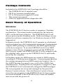
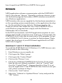
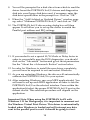
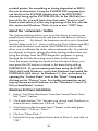
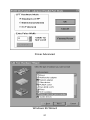
1
Portman 4x4 ™
MANUAL
Table of Contents
FCC Class B and CE Compliance
Features
Package Contents
Basic Theory of Operation
MIDI Modes
SMPTE Modes
Front and Back Panel
Front Panel
Dip Switch Settings
Back Panel
Mechanical Installation
About the Parallel Cable
About Your Printer Port
Running the DOS Diagnostics
1. Internal Hardware Test
2. Internal Buffer Test
Delay Value
3. Transmit/Receive
4. Receive Interrupt Test
5. SMPTE I/O Test
Drivers
Windows 3.1 and 3.11 Driver Installation
About the "<Advanced>" Button
Windows 95 Driver Installation
Remote Control Software
Remote Control Software Windows Installation
Remote Control Windows 95 Installation
Typical System Set-up — Fig. 1
Configuring Applications
SMPTE/MIDI Time Code Tutorial
What is SMPTE (Time Code)?
What is MIDI Time Code (MTC)?
About Frame Rates
What Frame Rate and Settings Should You Use?
SMPTE and MTC User Bits
SMPTE Offset
Flywheeling
3
4
5
5
5
6
8
8
8
9
10
11
13
13
15
15
16
16
17
17
18
18
20
20
22
22
24
23
25
26
26
27
28
29
29
30
31
Syncing to SMPTE
Recording a SMPTE Stripe (Writing SMPTE)
Syncing to a SMPTE Stripe
The Remote Control Software
SMPTE Setup
Patchbay Setup
Menus
File
Hardware
Help
Using the Patchbay Features
Trouble-Shooting
General Trouble-Shooting
Patchbay Trouble-Shooting
Interface Trouble-Shooting
Syncing Trouble-Shooting
Lifetime Limited Warranty
32
32
34
35
35
36
36
36
37
37
38
40
40
40
40
43
45
READ THIS! ...
READ THIS! ....
Included with PORTMAN 4x4/S is a factory diskette containing diagnostic software, Windows drivers and a
Window application. To install these programs, read this
manual and carefully follow the installation procedures.
Please thoroughly read and follow the installation instructions before physically installing your PORTMAN 4x4/S.
FCC Class B and CE Compliance
WARNING: This equipment has been tested and found to comply with the limits for a CLASS B digital device, pursuant to Part 15 of the FCC Rules. These limits are designed to provide reasonable protection against harmful interference in
a residential installation. This equipment generates, uses and can radiate radio
frequency energy and, if not installed and used in accordance with the instructions contained in this manual, may cause harmful interference to radio and television communications. However, there is no guarantee that interference will not
occur in a particular installation.
If this equipment does cause harmful interference to radio or television reception, which can be determined by turning the equipment off and on, the user is
encouraged to try to correct the interference by one or more of the following
measures: 1) reorient or relocate the receiving antenna; 2) increase the separation
between the equipment and the receiver; 3) connect the equipment into an outlet
on a circuit different from that of the receiver; 4) consult the dealer or an experienced audio television technician.
NOTE: Connecting this device to peripheral devices that do not
comply with CLASS B requirements or using an unshielded
peripheral data cable could also result in harmful interference
to radio or television reception.
The user is cautioned that any changes or modifications not expressly approved
by the party responsible for compliance could void the user’s authority to operate this equipment.
To ensure that the use of this product does not contribute to interference, it is
necessary to use shielded I/O cables.
FCC ID#: IMJPORTMAN4
This product also complies with European CE requirements.
3
Features
Thank you for purchasing the Midiman PORTMAN 4x4/S parallel port MIDI interface. The PORTMAN 4x4/S offers professional
MIDI and SMPTE performance in an external interface that
attaches to any standard, bi-directional, ECP or EPP PC parallel
port.
The PORTMAN 4x4/S is a third-generation product based on
proven Midiman PORTMAN and Syncman interface technologies. The PORTMAN 4x4/S has the following features:
•
High-speed proprietary architecture outperforms other
externally-connected MIDI interface boxes.
•
Four independent MIDI Outs and MIDI Ins provide 64
channels of MIDI output and 64 channels of MIDI input.
•
Large high-performance data buffers ensure full MIDI
throughput with absolutely no data loss.
•
Built-in SMPTE Time Code reader/writer/regenerator
supports all standard time code formats.
•
Supports SMPTE User Bits.
•
Adjustable SMPTE flywheel and Jam Sync.
•
Windows driver works with all Windows applications that
are Windows Multimedia Extensions (MME) compliant.
•
Windows driver is multi-client (supports full MIDI bandwidth on all ports -- even when using multiple programs).
•
Completely controllable and configurable via Windows
Remote Control software.
•
Automatically stores and reloads user settings from last
session.
•
Operates as MIDI Patchbay when not in interface mode.
•
Patchbay settings are stored internally so PORTMAN
4x4/S can be used without connection to computer
4
Package Contents
Included in the PORTMAN 4x4/S package should be:
• The PORTMAN 4x4/S interface unit.
• DB-25 to Centronics parallel cable.
• DC 9v 500 ma power supply (US only).
• This instruction manual.
• A drivers, applications and diagnostics disk.
Basic Theory of Operation
MIDI Modes
The PORTMAN 4x4/S has two modes of operation: Patchbay
and Interface. The current mode is indicated by the indicator
LED’s on the left front of the box. The PORTMAN 4x4/S will
always power up into Patchbay mode. Mode switching is accomplished via software command (i.e. by Windows drivers or DOS
diagnostics).
In Interface mode, the PORTMAN 4x4/S operates as a dedicated
multi-port interface with 4 independent inputs and 4 independent
outputs. MIDI patching is controlled by the MIDI application(s)
on the host computer. To use the PORTMAN 4x4/S as a MIDI
interface, turn off your computer’s power and the PORTMAN
4x4/S power, connect the PORTMAN 4x4/S to the computer with
the supplied cable, power up the PORTMAN 4x4/S, and finally
power up the computer.
In Patchbay mode, the MIDI inputs are routed to MIDI outputs
according to 32 different user programs. A user program specifies
the routing/merging between MIDI inputs and outputs. Any of
the 4 MIDI Ins may be routed to any or all of the 4 MIDI Outs
simultaneously. If multiple Ins are assigned to a single Out, then
the PORTMAN 4x4/S automatically merges the MIDI messages.
The user programs are set up and managed by the provided
Remote Control software. Once the Remote Control software
stores the user programs to the PORTMAN 4x4/S, the programs
are stored internally in the PORTMAN 4x4/S and will remain
intact even with the power off.
5
When the PORTMAN 4x4/S powers up, it enters Patchbay mode
and configures itself to Program 00. It may be switched to other
programs via MIDI Program Change messages. The Program
Change messages must be received at MIDI IN4 and on MIDI
Channel 16 only. These program changes only apply to Patchbay
mode and not Interface mode. When sending Program Change
messages to the PORTMAN’s IN4 it will accept program numbers
00 through 31. Above 31, the program numbers wrap-around. For
example, program 32 selects PORTMAN 4x4/S user program 00,
program 33 selects PORTMAN 4x4/S user program 01, etc.
For stand-alone patchbay operation, the PORTMAN 4x4/S may
be left attached to a computer that is turned off. However, the
PORTMAN 4x4/S should always be powered up before the computer. The parallel cable should not be connected or disconnected
while either is powered up.
Important note: Holding the Write Button while powering up
the PORTMAN 4X4/S will reset all internally-stored values to
their factory defaults: all User programs become ALL OUTS =
ALL INS merged, SMPTE User Bits are zeroed, SMPTE
Flywheel is set to 15 and the SMPTE Write Offset is set to
01:00:00:00.
SMPTE Modes
On the right side of the front panel, there are two LEDs which
indicate the current SMPTE mode. When the Read LED is lit, the
PORTMAN 4x4/S has auto-detected the incoming SMPTE format
and is locked to incoming SMPTE time code. The Read LED will
blink rapidly in sync with each frame and therefore blinks slightly
faster for 30/30DF then it does for 24/25 rates. To indicate bad
incoming frames, the LED will blink off for approximately 0.25
seconds for each bad frame.
When the Write LED is lit, the PORTMAN 4x4/S is striping
SMPTE. The Write LED will blink rapidly in sync with each outgoing frame and therefore blinks slightly faster for 30/30DF then
it does for 24/25 rates.
6
When both Read and Write LEDs are blinking, SMPTE Regenerate
mode is selected and the box is waiting to acquire incoming
SMPTE. This mode is selected by setting the “Regen” dip switch
ON. When the “Regen” dip switch is set ON, SMPTE Write is disabled. Once locked to the incoming SMPTE, the Regenerate LED
pair blinks in the same manner as the Read LED blinks in SMPTE
Read mode.
In Write mode, the SMPTE format always matches the format set
up on the SMPTE Format DIP switches. These DIP settings affect
Write mode only. On the other hand, when SMPTE is being Read
or Regenerated, the output format is always the same as the input
format. Automatic format detection will take between 3 and 31
frames, depending on the incoming format and the value of the
first SMPTE frame received. When using the PORTMAN with a
sequencer program synced to MIDI Time Code, at least 5 seconds
of pre-roll (always a good idea, anyway) are recommended for
proper synchronization.
In Patchbay mode, SMPTE can only be regenerated or written. In
interface mode, SMPTE can be read, regenerated or written.
7
Front and Back Panel
Front Panel
Portman 4x4/S
l
(insert Front Panel fig 1. here) W
1
INTER
IN 1
1.
REGEN
MIDI OUT
FORMAT
PC MIDI INTERFACE/SMPTE SYNC
MIDI
PATCH
OUT 1
2.
IN 2
3.
OUT 2
4.
2
3
4
RESET
MIDI IN
5.
6.
READ
RITE
OFF
REGEN
ON
WRITE
7.
8.
9.
10.
2.
Patchbay indicator LED - This LED, when lit, indicates that the
PORTMAN 4x4/S is operating in Patchbay mode.
3.
MIDI Connectors - These connectors are for MIDI In 1, Out 1, In 2,
and Out 2 respectively.
4.
MIDI Out LEDs - These LEDs indicate MIDI Out activity on the
indicated ports (1 through 4).
5.
MIDI In LEDs - These LEDs indicate MIDI In activity on the indicated ports (1 through 4).
6.
Reset switch - This switch, when pushed, will send Note Off and
Controller reset messages on all MIDI ports and channels. It then
returns the PORTMAN 4x4/S to its previous mode.
7.
DIP switches - The right most two dip switches set the SMPTE Write
Format. The left most switch enables and disables SMPTE
Regeneration. Please note: the SMPTE format set on the Format DIP
switches may be overridden by using the PORTMAN 4x4/S Remote
Control software. The SMPTE Write format, as set by the two right
Format dip switches, have the following settings:
FORMAT
Interface indicator LED - This LED, when lit, indicates that the
PORTMAN 4x4/S is operating in MIDI Interface mode.
FORMAT
1.
put dip switch Write format figure here
OFF
OFF
24 Frames
25 Frames
FORMAT
ON
FORMAT
ON
OFF
OFF
30 Drop
30 Non-drop
ON
ON
8
8.
Write switch - Starts and stops the SMPTE writer. When pressed and
immediately released, the SMPTE time code starts writing at the preset start offset. The Writer may be stopped by pressing the Write
switch again. To manually increment the starting offset, press and
hold the Write switch -- this will increment the stored start offset by
1 hour every time the Write LED blinks. Release the Write switch to
start writing at the new offset. This start offset becomes the new
default start offset. SMPTE writer start/stop, plus start offset, are
also controllable via the PORTMAN 4x4/S Remote Control software.
9.
Read LED - This LED, when lit, indicates that the PORTMAN is in
SMPTE read mode. It will blink in sync with the incoming frame
rate. Bad SMPTE frames are indicated by the LED going off for
approximately 1/4 second. When this LED is lit in combination with
the Write LED the PORTMAN is in SMPTE regeneration mode.
10. Write LED - This LED, when lit, indicates that the PORTMAN 4x4/S
is currently writing SMPTE. When this LED is lit in combination
with the Read LED the PORTMAN is in SMPTE regeneration mode.
Back Panel
IN 3
OUT
IN
11.
MIDI
PC PRINTER PORT
(insert Back Panel fig. 2 here)
12.
13.
OUT 3
IN 4
14.
▲
SMPTE
9VDC
OUT 4
15.
11. SMPTE In - This jack connects to the Tape Out or Sync Out of your
tape deck to receive SMPTE Time Code.
12. SMPTE Out - This jack connects to the Tape In or Sync In of your
tape deck to transmit SMPTE Time Code.
13. PC Printer Port - Connects to standard or enhanced Centronics
Parallel ports with the supplied parallel cable.
14. MIDI Connectors - These connectors are for MIDI In 3, Out 3, In 4,
and Out 4 respectively.
15. Power Connector - This connects to the 9v DC 500 ma power supply
included with your PORTMAN 4x4/S. If you ever need to replace
this power supply, make sure that it will supply at least 500 ma and
has the center pin positive.
9
Mechanical Installation
To mechanically attach the PORTMAN 4x4/S to your computer,
do the following:
1. Turn off both your computer and the PORTMAN 4x4/S.
2. Locate the connector for the printer port (LPT1 or LPT2) on
the back of your computer.
3. Attach one end of the supplied parallel cable to the printer
port and the other to the PORTMAN 4x4/S rear connector
labeled “PC Printer Port”. Make sure that the connectors are
firmly joined and that you have tightened the thumbscrews
on the computer side of the cable.
4. Connect the power supply to the PORTMAN 4x4/S and plug
it into a convenient power outlet. Although it won’t hurt your
PORTMAN 4x4/S to leave it plugged in, we recommend having it on a power strip so you can turn it on and off as you
need it.
5. Connect your MIDI gear to the PORTMAN 4x4/S. Remember
to think of these connections in terms of signal flow.
Information goes OUT of your keyboard to the IN of the
PORTMAN, OUT of your PORTMAN and IN to your keyboard.
6. Connect your tape deck or other SMPTE device to the 1/4”
SMPTE phone connectors. Connect the PORTMAN SMPTE
jack labeled “IN” to the proper Tape Out or Sync Out of your
tape deck. Connect the PORTMAN SMPTE jack labeled
“OUT” to the proper Tape In or Sync In jack of your tape deck.
7. Move your computer back to its original position. You may
now turn on your computer.
10
About the Parallel Cable
The PORTMAN 4x4/S ships with a suitable parallel cable.
However, if you need to replace this cable or want a longer one,
there are certain requirements that you should be aware of. A
Centronics cable that works with your printer will usually, but not
always, work with a PORTMAN. There are at least two reasons
why it might not work:
1. The PORTMAN runs at a much higher data rate than a printer, and therefore often prefers a shorter (6 feet or less) and
higher quality cable with all of its ground wires present.
2. The PORTMAN uses some of the signals of the Centronics
port that are unused by the printer. Because of this, the PORTMAN requires a cable that has all 25 wires present and connected according to Centronics specification. Not all printer
cables have all 25 wires connected.
If you are having trouble using the PORTMAN with your present
printer cable and need to purchase one that will work with the
PORTMAN, you can purchase one from MIDIMAN directly,
through a Midiman Dealer or from your local electronics supply
store. Midiman has found at least one easily-obtainable cable that
is fully Centronics-compliant and verified to work with the
PORTMAN:
Manufacturer:
Part #:
GC Electronics
45-201-BU
In the event that you are going to purchase a cable yourself and
you can not locate a GC Electronics cable, use the following chart
as a guide to the Centronics specification:
11
Line Name
-Strobe*
D0
D1
D2
D3
D4
D5
D6
D7
-ACK
Busy
PE
SLCT
-AUTOFD
-Error
-INIT
-SLCT In
Ground
DB25-S (25-pin end)
1
2
3
4
5
6
7
8
9
10
11
12
13
14
15
16
17
18 through 25**
Centronics
1
2
3
4
5
6
7
8
9
10
11
12
13
14
32
31
36
16,19-30,33
*
A dash in front of a line name denotes a line that is functionally active when low.
**
The ground lines on the DB25s end of the cable can tie to any of the ground pins
on the Centronics side, but they must run as separate wires and not share any
pin at the Centronics end (none bridged or tied together.)
Typically, if you ask your dealer for a 6-foot Centronics cable with
ALL 25 wires implemented, you will get a cable that matches the
above table.
Note: Good quality cables with lengths up to 30 feet have been
verified to work successfully with PORTMAN 4x4/S.
12
About Your Printer Port
The driver for the PORTMAN 4x4/S needs to be configured
according to the Port Address and the Interrupt Request Number
(IRQ) of the parallel printer port that you have the PORTMAN
physically connected to. Basically put, this information describes
where the computer should look for the device and the priority of
each device connected to or installed in your computer.
There are a couple of ways to find out what your port's address
and IRQ are. The simplest way is to run the included program
called LPT.EXE as described below. This program must be run
from DOS. If you are presently in Windows, you must quit (Exit
Windows) your Windows session before executing LPT.EXE.
Another way to get information about your computer’s
Centronics port is to consult your computer manual or contact
your manufacturer directly.
Running the DOS Diagnostics
Now that the PORTMAN 4x4/S is connected to the computer,
there are a few short diagnostic programs to run. On the included
diskette there is a directory called 4X4DIAGS which contains the
LPT.EXE and P4X4DIAG.EXE programs. These programs verify
the setup of your computer and the functionality of the PORTMAN 4x4/S.
Important Note: Both of these diagnostic programs must be run
from DOS, since Windows can’t always give access to the lowerlevel functions of the computer. If you are using Windows 3.1x,
you must exit Windows now. If you are using Windows 95, you
must choose Shutdown and then select “Restart in MS-DOS
mode”.
To run these programs, insert the MIDIMAN factory diskette into
your disk drive. Make sure you are accessing the proper disk
drive by typing either “A: <Enter>” or “B: <Enter>” at the DOS
prompt. Next, get into the 4X4DIAGS directory by typing “CD
4X4DIAGS <Enter>“. You will know you’re in the right place
when the prompt reads something like “A:\4X4DIAGS>“. Once
you see this prompt, type in “LPT” and hit the enter key. This pro13
gram will search for the I/O address and IRQ of your parallel
port. While most PCs have the same setting (I/O address 378h,
IRQ 7) for LPT1, enough computers, especially laptops, use different settings that it is a good idea to check first. Just follow the
instructions on the screen and don’t forget to write down the settings the program gives you.
Next, type P4X4DIAG <Enter> at the DOS prompt to execute the
diagnostics program. Once in the program you can press your
computer’s <Enter> key to toggle through the available LPT settings until it matches the setting for your port that you found
when running the LPT program described above.
Next, connect a single MIDI cable from In 1 to Out 1 on the front
connectors of the PORTMAN 4x4/S. This cable will be used to
“loop back” data and verify MIDI transmission and reception of
your PORTMAN.
IMPORTANT: When performing this test be sure that MIDI In 1
is connected to MIDI Out 1 on the front of the PORTMAN, otherwise the diagnostics will indicate that your unit is failing.
Now connect the SMPTE In jack to the SMPTE Out jack using a
standard male-to-male 1/4” phone cable. This cable will be used
to “loop back” and verify SMPTE transmission and reception.
Move the cursor down to the “Run Tests” line and press <Enter>.
The program should run through 5 tests. If it fails any of these
tests, go back and make sure that you have followed these
instructions exactly. Once the first run of tests has passed, toggle
the Loopback settings to other combinations of MIDI Ins and
Outs, move the connecting MIDI loop back cable, and re-run the
tests to make sure that all of your PORTMAN inputs and outputs
are working properly.
When you run P44DIAG.EXE, you will get a title screen showing
the test revision number and a list of parameter settings. By this
time you should know what your Port Address and IRQ settings
are. If you don’t, go back and read the above installation instructions over again. You will need this information to run the diagnostics successfully.
14
The diagnostic software user interface is quite simple. Just use
the arrow keys to move from one line to the next and the <Enter>
key to move through the different options for each line until they
match the desired values. Move the cursor to the “Run Tests” line
and press the “Enter” key. P4X4DIAG.EXE will then test the following four areas:
1. Internal Hardware Test
This will indicate whether the PORTMAN, your computer, and
the Centronics cable are all connected properly and working. If
working successful, the test will return the PORTMAN’s internal
firmware revision number.
If your PORTMAN fails this test, it could mean a bad PORTMAN
or other hardware failure, but most often it means one of a few
very specific things:
a.) You have the incorrect port settings in the diagnostic program.
b.) PORTMAN power is not properly connected.
c.) Your cable is not fully Centronics compatible or is defective.
d.) Your computer’s parallel port is configured incorrectly or is
defective.
e.) You need to adjust the Delay Pulse setting starting at 75 and
run the test again. If it fails then keep adjusting by increments
of 25 until it passes. This is due to the speed of the parallel
port.
2. Internal Buffer Test
This test checks the PORTMAN's ability to handle the flow of
data through its internal circuitry and across the parallel cable. If
it fails, it most often is due to one or more of the following:
a.) Your computer’s parallel port is slightly slower than the
PORTMAN, and you need to compensate by increasing the
Delay Pulse setting in the diagnostic software.
b.) Your computer’s parallel port mode is not set to match the
H/W Mode setting in the diagnostic program.
15
c.) The PORTMAN is defective. This is extremely rare as the
PORTMAN units are tested rigorously at the factory before
shipping. If you think this is the case, please contact MIDIMAN Technical Support.
Delay Value
Due to the lack of standardization among different computer
manufacturer's designs, some parallel ports are slower than others. Because the PORTMAN operates at high data rates, some
computer’s parallel ports are slightly slower than the PORTMAN.
This may be compensated for by increasing the Delay Pulse setting in the diagnostic software to account for your particular parallel port.
Most of the time the Delay Pulse should both be set to 0. If you
find that your computer is testing erratically on the Internal
Buffers test and/or Transmit/Receive test, you should boost the
Delay Pulse value ever so slightly. Changing the Delay Pulse will
not adversely affect your MIDI performance because even with a
huge Delay Pulse setting, the computer-to-PORTMAN speed is
much faster than MIDI.
Printer Port Hardware Modes
Most computers’ parallel printer ports operate in one or more of
the following modes: Compatible, Bi-directional, EPP, and ECP.
The mode is usually manually set in the CMOS setup of the computer (please see your computer’s user guide for more information). While Compatible mode works with almost all printer
ports, it is also the lowest performance. If available, choose ECP
or Bi-directional first. Then when running the diagnostic software
(or drivers), set H/W Mode to match the printer port mode
you’ve selected in your CMOS setup. If the higher performance
settings do not work with your computer, back off to Compatible
Mode, which is adequate for MIDI data rates.
3. Transmit/Receive
If your PORTMAN fails this test, it usually indicates a bad MIDI
connection. It could also be an indication of a specific communication problem.
If this part of the test fails reporting:
16
Transmit/Receive Test: Fail
Tx=0h Rx=Timeout
a.) Make sure that your MIDI cable(s) are good.
b.) Make sure that you have a MIDI cable connected between the
PORTMAN MIDI In and the PORTMAN MIDI Out selected in
the diagnostic program. Your MIDI instruments should not be
connected for this test; it is a closed-loop test with one MIDI
cable connected between the MIDI jacks of the PORTMAN.
c.) Adjust the Delay Pulse setting in the diagnostic program.
d.) Ensure the H/W Mode setting matches your computer’s parallel port mode.
4. Receive Interrupt Test
This test checks the reception of data from the PORTMAN under
interrupt (IRQ) control. If this test fails, it is almost always IRQrelated.
Most computers use IRQ7 for LPT1 and IRQ5 for LPT2. If you
have the PORTMAN connected to LPT1 on your computer, and
have IRQ=7 set in P4X4DIAG.EXE, but it fails the Receive
Interrupt Test, you could have a computer with IRQ5 assigned to
LPT1. Try changing the IRQ setting to IRQ5 in the
P4X4DIAG.EXE program.
If you are unsure what your port IRQ is or how to find out, please
see the section in this manual titled "About Your Printer Port"
which immediately precedes this section, or you can consult your
computer owner's manual.
It is also possible that you have an older computer that by design
does not have an IRQ internally attached to its parallel port. If the
computer is a desktop model, you can usually add an inexpensive
add-on card to give this machine more LPT ports, with IRQs. On
a newer machine, it is possible that the IRQ is disabled on your
parallel port, and simply needs to be switched on. For information regarding this, consult your computer owner's manual, or
computer manufacturer directly.
5. SMPTE I/O Test
This test makes sure that the SMPTE In and Out jacks are functioning properly. If this test fails, make sure that the cable you
17
have looped from SMPTE In to SMPTE Out is good.
Drivers
MIDI application software communicates with the PORTMAN
4x4/S via software “drivers.” Basically, a software driver is a special dedicated program that makes a MIDI interface accessible to
any Windows application.
MIDI interface drivers are supplied by the hardware manufacturer, the operating system manufacturer, or the application developer. On the included factory diskette, Midiman supplies the
Windows drivers that enable the use of the PORTMAN 4x4/S
with Windows programs that comply with the Windows
Multimedia driver standards.
In the DOS environment, each DOS application requires its own
unique (and usually proprietary) set of drivers. Consequently, the
PORTMAN 4x4/S can only be used with a DOS program if a specific PORTMAN 4x4/S driver is written for that program. Please
contact the developer of your DOS-based application for PORTMAN 4x4/S support.
Windows 3.1 and 3.11 Driver Installation
To install the PORTMAN 4x4/S Windows 3.1x MIDI drivers onto
your system do the following:
1. Start Windows as you usually do.
2. Click open the *Main* group.
3. Click open the *Control Panel*.
4. Click on the *Drivers* icon.
5. Check for a Midiman PORTMAN 4x4/S entry. If one exists,
then the driver is already installed—click on “Cancel” and
close the *Control Panel* -- then go directly to Step 13 to set
up your application. If the PORTMAN 4x4/S driver is not present, please continue to Step 6.
6. Click on the “Add” button.
7. Select the “Unlisted or Updated Driver” entry and push the
“OK” button.
18
8. You will be prompted for a disk drive from which to read the
driver. Insert the PORTMAN 4x4/S drivers and diagnostics
disk into your floppy disk drive and, if necessary, enter the
disk drive specification in the prompt box. Click on “OK”.
9. When the “Add Unlisted or Updated Driver” window pops
up, select “Midiman PORTMAN 4x4/S” and click on “OK”.
10. The PORTMAN 4x4/S driver setup dialog box will then
appear. It will allow you to set up the driver to match the
Parallel port address and IRQ settings.
(Insert Driver Setup SNAG 4 screen shot here)
11. If you needed to set a special H/W Mode or Delay factor in
order to successfully pass the DOS diagnostics, you should
click on the “Advanced” button and go set those parameters.
See the “About the <Advanced> Button” section below.
12. In order for Windows to install the new driver completely,
you will now be required to exit and restart Windows.
13. As you are restarting Windows, the driver will automatically
calibrate the PORTMAN 4x4/S to your system.
14. After restarting Windows, run your MIDI application(s). You
will need to set up each MIDI application in order to use the
PORTMAN 4x4/S as the selected interface. From within the
application(s) select the proper PORTMAN 4x4/S port as the
current device. This selection procedure will depend on the
application.
Important Note: When using the PORTMAN 4x4/S with
Windows 3.11 for Workgroups, it is important to comment out
the Windows Virtual Print Driver. This driver is automatically
loaded when Windows is loaded and will intercept any data
sent to the parallel port to see if it should be going to a net19
worked printer. For something as timing dependent as MIDI,
this can be disastrous. Using the SYSEDIT.EXE program (you
can find it in the SYSTEM subdirectory of the WINDOWS
directory) bring up the SYSTEM.INI file. In the [386 Enh] section of the file, you will find a line that reads: “device=*vpd”.
Insert a semi-colon (;) at the very beginning of the line, save the
file, and restart Windows. That’s it, you’re now “VPD” free.
About the "<Advanced>" Button
The Advanced Setup allows you to set the driver to match your
parallel port’s hardware mode, and also to add delay for slower
printer ports.
By default the hardware mode is set to Standard
and the delay is set to 0. Once a valid set of Port Address and IRQ
are set and Windows is reloaded, the PORTMAN driver will
allow you to calibrate the delay values automatically. You should
not attempt to directly change the delay setting without first verifying the settings from the DOS diagnostic program, or going
through the Trouble-Shooting section later in this manual.
Once the proper settings are made in the Advanced Setup, you
may press the OK button to return to the main Setup dialog.
IMPORTANT: If you encounter problems using the PORTMAN 4x4/S with Windows, verify that Windows has loaded the
PORTMAN 4x4/S driver. In Windows 3.1, this can be done by
opening the *Control Panel* icon in the *Main* Group and
clicking on the *Drivers* icon. For further information on setting up drivers under Windows, see the “Windows 3.1 and 3.11
Driver Installation” section.
Windows 95 Driver Installation
1. Select “Add New Hardware” from the Control Panel. Press
the “Next>“ button.
2. Click radio button “No” because you do not want Windows to
search for new hardware. Click on “Next>“.
3. Scroll down in the box and select “Sound, video and game
controllers”. Click on “Next>“.
4. Click on “Have Disk...”.
5. Insert the factory supplied driver disk in Drive A: and click on
“OK”.
20
Driver Advanced
Windows 95 Wizard
21
6. Select the Midiman PORTMAN 4x4/S driver from the list box
and click on “OK”.
7. Click on “Finish”. The rest of the installation is the same as
from Step 10 of the “Windows 3.1 Driver Installation”.
IMPORTANT: With Windows 95 make sure to click on the
“Enable Driver” box. If you fail to do this the PORTMAN 4x4/S
driver will not be enabled.
ATTENTION: If you experience a problem with the Portman
4x4/s not initializing, there’s a setting change you’ll need to
make under the advanced settings of the driver. This is due to
the speed of the system and parallel port. Go to the “Control
Panel,” double click on “Multimedia,” click on the “Advanced”
tab, double click on “Midi Devices and Instruments.” There
you’ll see the outputs for the Portman 4x4/S, highlight output
number one, click on “Properties” and then click on settings.
You will see settings for the driver, click on the advanced button. Adjust the “Extra Pulse Width” to 75 by incrementing up.
Click on OK to get out and then re-boot Windows for this to
take effect. If you still have problems or it’s not initializing then
adjust the Extra Pulse Width by 25. We have seen some systems
requiring settings up to 200.
Remote Control Software
Included with your PORTMAN 4x4/S is Windows Remote
Control software that enables you to configure and control the
PORTMAN 4x4/S SMPTE functions, and set up patchbay programs from your PC. The software enables you to set user bits,
frame format, flywheel and write start time (offset), as well as
start and stop SMPTE writing. Different Remote Control software
settings may be saved to disk as “configurations” and reloaded at
a later time.
Remote Control Software Windows Installation
To install the PORTMAN 4x4/S Remote Control application into
Windows, make sure you are in the Windows Program Manager
and insert the PORTMAN 4x4/S Remote Control diskette into
your disk drive. Next, under the “File” menu select “Run...”.
When prompted to enter a command line type either
22
MIDI In
MIDI Out
PC Computer
Tape In
Tape Out
Tape Deck
Out4 In4 Out3 In3 Printer
MIDI
Port
Out In
SMPTE
23
Portman 4x4/S
(top view)
MIDI
In1 Out1 In2 Out2
MIDI Out
MIDI In
Master Keyboard
(front panel)
MIDI Out
MIDI In
MIDI Out
MIDI In
Master Keyboard
MIDI Sound Module 1
Master Keyboard 2
Master Keyboard
Typical System Set-up — Fig. 1
MIDI Sound Module 2
A:SETUP.EXE if your diskette is in drive A, or type B:SETUP.EXE
if your diskette is in drive B. Now, select the OK button. The
SETUP program will automatically guide you through the installation and create a MIDIMAN group with a PORTMAN 4x4/S
Remote Control icon.
Remote Control Windows 95 Installation
Windows 95 installation is done as follows:
1. From “Settings” in the “Start” menu, choose Control Panel.
2. Click on “Add/Remove Programs”.
3. Click on “Install”.
4. The Wizard should find the SETUP.EXE program on the A:
drive. If it can’t find it, you will have to type “A: SETUP.EXE”
at the prompt.
5. Click on “Finish”. The Wizard should now install the Remote
Control Windows program.
Typical System Set-up
A typical system set-up (see Fig. 1) consists of your computer
with the PORTMAN 4x4/S installed, your sequencing software, a
tape deck, a Master Keyboard, and additional MIDI sound modules or keyboards. This set-up is connected as follows:
•
The MIDI Out of your Master Keyboard is connected to MIDI
In 1 on the front of the PORTMAN 4x4/S.
•
The MIDI Out 1 on the front of the PORTMAN 4x4/S is connected to the MIDI In of your Master Keyboard.
•
The MIDI Out of your Master Keyboard 2 is connected to
MIDI In 4 of the PORTMAN 4x4/S. Why connect a master
keyboard to MIDI In 4, you ask? When you are using the
PORTMAN 4x4/S in patchbay mode, program change messages are received on MIDI In 4, Channel 16. By connecting a
master controller to In 4, you don’t have to change cabling
when using the PORTMAN 4x4/S as a patchbay.
•
The MIDI Out 4 of the PORTMAN 4x4/S is connected to the
MIDI In of your Master Keyboard 2.
24
•
The Tape Recorder Tape Out (or Sync Out) is connected to the
PORTMAN 4x4/S SMPTE jack labeled “IN”.
•
The Tape Recorder Tape In (or Sync In) is connected to the
PORTMAN 4x4/S SMPTE jack labeled “OUT”
•
Up to three additional MIDI sound modules or keyboards
may have their MIDI Ins connected to the remaining PORTMAN 4x4/S MIDI Outs. Optionally, the MIDI Outs of these
additional MIDI units may be connected to the remaining
PORTMAN 4x4/S MIDI Ins.
Configuring Applications
Once the Windows drivers for the PORTMAN 4x4/S have been
installed, you will need to configure your MIDI applications to
take advantage of the PORTMAN 4x4/S drivers. The manner in
which each application does this is different, so it is impossible to
go over all possible scenarios here. However, most Windows
MIDI applications have a configuration or settings dialog box
(sometimes called “MIDI Devices”) that specifies the MIDI input
and output ports the program will be communicating with. If
your PORTMAN 4x4/S drivers are properly installed, you should
see the PORTMAN 4x4/S MIDI and SMPTE ports listed in this
dialog box.
In its factory default configuration, the PORTMAN 4x4/S
looks like ten independent devices, 5 of which are inputs and
5 are outputs. From the application’s configuration dialog,
these devices are:
Inputs
IN1 - PORTMAN 4x4/S
IN2 - PORTMAN 4x4/S
IN3 - PORTMAN 4x4/S
IN4 - PORTMAN 4x4/S
SMPTE/Status - PORTMAN 4x4/S
Outputs
OUT1 - PORTMAN 4x4/S
OUT2 - PORTMAN 4x4/S
OUT3 - PORTMAN 4x4/S
25
OUT4 - PORTMAN 4x4/S
Control - PORTMAN 4x4/S
Inputs 1 through 4 correspond to the physical MIDI In connectors
1 through 4, and the SMPTE/Status corresponds to the 1/4”
SMPTE Input connector. Outputs 1 through 4 correspond to the
physical MIDI Out connectors 1 through 4, and the SMPTE
Control corresponds to the SMPTE processor command port.
Although the SMPTE/Status driver transfers time code data into
the program, the SMPTE Control driver does not actually transfer
SMPTE data out of the program. Instead, it is used by some applications to configure and control (Start Writing, Stop Writing, User
Bits, SMPTE format, Patchbay User Programs, etc.) the processor
that resides in the PORTMAN 4x4/S.
In order to route data between the application and specific ports
on the PORTMAN 4x4/S, select (from within your application)
the appropriate drivers of the above list. Many newer applications
(Cakewalk for Windows for example) will allow you to select and
access all the PORTMAN 4x4/S ports within the same session.
Other applications (for instance, as of this writing, Master Tracks
Pro 6.0 can only handle two MIDI ports) will limit the number of
input and output drivers you may select at one time.
SMPTE/MIDI Time Code Tutorial
This section of the manual gives a brief tutorial on various SMPTE
topics. This section is not by any stretch of the imagination an
exhaustive treatment of time code or syncing. Instead it is included to make the PORTMAN 4x4/S SMPTE functions more understandable.
What is SMPTE (Time Code)?
SMPTE is a time coding standard which was developed in 1967
by the Society of Motion Picture and Television Engineers
(SMPTE) to be used in video editing. SMPTE attaches a unique
time stamp (80 bits of information) to each frame of video or film.
SMPTE readers may then extract that time information and synchronize other devices to it. Because SMPTE may be encoded as
an actual audio signal, it also lends itself to audio applications
26
and can be read from audio tracks for synchronization purposes.
The SMPTE Time Code consists simply of:
Hours : Minutes : Seconds : Frames.
Therefore a typical SMPTE time code reading would be:
01 : 25 : 42 : 17
which represents the time 1 hour : 25 minutes : 42 seconds : 17
frames.
The original SMPTE Time Code was Longitudinal Time Code
(LTC). “Longitudinal” means that the code is laid down in a continuous audio stripe along the length of the tape (longitudinally).
The PORTMAN 4x4/S is designed to write this longitudinal time
code (LTC) as well as read and convert it to MIDI Time Code
(MTC).
What is MIDI Time Code (MTC)?
MIDI Time Code (MTC) is the MIDI implementation of SMPTE.
MTC was first standardized in 1987 as a method of synchronizing
MIDI software and hardware sequencers, as well as drum
machines. Later it was also adopted by digital audio recording
software and hardware manufacturers as a method of synchronizing to audio and video gear. Interfaces such as the PORTMAN
4x4/S perform the essential task of reading longitudinal SMPTE
from a audio and/or video tape and converting it to MTC for use
by MIDI applications.
MTC implements a special System Common MIDI message that is
sent four times per frame (every quarter-frame). Each of these
“quarter-frame” messages is two bytes long and contains one
eighth of a complete time code value. A unit or program receiving
MTC must receive eight of these messages in order to construct a
the complete time. By the time 8 quarter-frame messages are
received and the complete time is constructed, that time value is
two frames old and it would seem that any synchronized program would always be two frames behind. Fortunately, most
sequencer programs add two frames to the received MTC in order
to derive the current time.
As long as a longitudinal SMPTE source is running, time code
may be read. However, what happens when it stops? The LTC is
27
no longer readable and the PORTMAN 4x4/S sends a standard
MTC NAK (signal not acquired) message to the application to
indicate the tape has become idle.
About Frame Rates
All SMPTE time code and MTC carry the same primary information, Hours:Minutes:Seconds:Frames. However, time code can be
written and read at different standard frame rates. These frame
rates designate the number of frames that each second is subdivided into. Different video, film and audio standard frame rates
have been adopted. These various standards and typical applications are:
Frame Rate
Application
24 frames/second
Motion Pictures
25 frames/second
European Video - both B/W & Color
30 drop frame
U.S. Color Video
30 non-drop
U.S. B/W Video and U.S. Audio
Black and white video frame rates were originally derived from
the A/C line frequency of the indigenous country (e.g. 50 Hz in
Europe, 60 Hz in the U.S.). In the U.S. when color video was
introduced, part of the black and white frame information was
used to encode the color information. The result was that the
color frame rate ran at an effectively slower rate of 29.97 frames
per second. This slower rate can be approximated by running at
30 frames per second and skipping 108 frames per hour in the
numbering scheme. This method of “dropping” 108 frames/hour
to slow the effective frame rate was termed “drop frame.” Hence,
the standard frame rate used when doing U.S. color video is
called “30 drop frame”. When running at a true 30 frames per
second, this is known as “30” or sometimes “30 non-drop”.
As listed in the above table, in the U.S. and other “NTSC” countries, black and white (30 non-drop) and color (30 drop) video
have different frame rates. While in Europe and all “PAL” countries, black and white and color video have the same frame rate of
25 frames per second.
28
What Frame Rate and Settings Should You Use?
The following table summarizes the frame rates that we recommend you use when striping SMPTE:
Application
Frame Rate
Audio Only
30 non-drop
Video - Color U.S.
30 drop*
Video - B/W U.S.
30 non-drop
Video - Color Europe
25
Video - B/W Europe
25
*
Note: If you are in the U.S. and using a PORTMAN 4x4/S to do
audio scoring or MIDI sequencing for your own video, then we suggest you use 30 non-drop instead of 30 drop. This is because dropframe is harder to work with since time calculations are more complicated. Non-drop will allow you to sync just as well drop-frame;
drop-frame is really only a necessity for broadcast purposes.
SMPTE and MTC User Bits
The SMPTE and MTC standards provide a means for users to
“stamp” their media with reference numbers of their own choosing. This is accomplished by setting aside some spare data (32
bits) within the time code message to be used as “User Bits.”
SMPTE and MTC allow you to encode these User Bits into the
time code message without affecting the time code itself.
Because there are 32 User Bits available, they can be further subdivided into 8 nibbles (one nibble = 4 bits), each of which can represent a binary- coded decimal (BCD) digit. A typical set of User
Bits might look like this:
04
19
03
12
This could be interpreted as April 19, shot 03, take 12. Although
this is one method of encoding user bit information, you may designate the digits in any way that you desire.
Many inexpensive sync boxes ignore User Bits because they have
no way to set them or read them. The PORTMAN 4x4/S User Bits
can be set via the Remote Control software and may be displayed
with some outboard device such as the MIDIMAN SMPTE Time
Window. The User Bits are also transmitted via MIDI message to
29
the MIDI application you are using. If your sequencer is capable
of displaying User Bits information, then you may read the User
Bits there as well.
The PORTMAN 4x4/S is capable of reading and writing SMPTE
User Bit groups U1 through U8. The values of the User Bits output during writing may be set with the Remote Control software.
When reading User Bits from an incoming source, a MIDI User
Bits message is sent to the application each time sync is acquired
and whenever a change in User Bits is detected.
SMPTE Offset
An “offset” is the starting time of the first frame of time code and
may be set to any time value in the range 00:00:00:00 through
23:59:59:29. Usually, you can set your offset to any value in this
range, but sometimes the production environment will dictate the
offset requirements. The PORTMAN 4x4/S has a default write
offset of 01:00:00:00. If you need to change the offset time, you
may do so via the supplied Windows Remote Control software.
IMPORTANT: Try to avoid high offsets that may wrap around
(from 23:59:59:29 back to 00:00:00:00). Some programs become
confused by this wrap-around. Choose an offset that will allow
your entire session to be striped without rolling over the
24:00:00:00 time code value.
At times, you may be given a tape with SMPTE already on it. The
offset time on the tape you receive will affect the start time that
you set for your MIDI sequencing. For example, if the time code
on the tape starts at 02:00:00:00 (a 2-hour offset) and you need to
start your sequence playing 3 minutes, 30 seconds into the work,
you should set the sequencer start time to 02:03:30:00.
Because MTC requires 8 quarter-frame messages to send a full
frame of time code, a minimum of 2 to 4 frames will be needed for
a sequencer to first sync up to a running SMPTE. Therefore,
when syncing a MIDI sequencer or any program to time code, it is
a good idea to set your sequence start time to a few seconds later
than the offset of the time code on tape. In other words, give your
sequencer some time to acquire sync and stabilize before it begins
playing back. For example, if your tape starting offset is
01:00:00:00, then set the sequence start time to 01:00:05:00, which
30
is 5 seconds later. This is also known as a 5-second “pre-roll.”
Some sequencers will actually allow you to directly set the “preroll” time to a specific number of seconds. These programs will
automatically sync up to an incoming MTC source for that preroll amount, and then start playing.
Flywheeling
Due to the nature of magnetic tape, sometimes drop-outs occur on
the tape and leave gaps in the recorded time code. When a dropout or other media corruption occurs at the sync source and there
is a resulting period of corrupted time code, the PORTMAN
4x4/S continues to “flywheel,” outputting time code from the last
properly received frame and incrementing at the proper frame
rate. This flywheeling continues until valid time code reappears
on the PORTMAN 4x4/S SMPTE input or until a preset time-out
occurs. The length of this time-out period is called the “Flywheel
Time.” The PORTMAN 4x4/S flywheel time may be set to any
amount from 1 to 255 frames, or infinite. It is good practice to use
the shortest Flywheel setting that will work with the amount of
drop-out found on the media you are syncing to. Infinite flywheeling is also known as Jam Sync and may be used to continue
generating time code long after the time code source has expired.
31
Syncing to SMPTE
Recording a SMPTE Stripe (Writing SMPTE)
Before the PORTMAN 4x4/S can be used to synchronize to a
source audio and/or video tape, that tape must be encoded with
SMPTE time code. Sometimes you will be provided with a piece
of source material that already has SMPTE on it. In that case, you
are not required to record another SMPTE stripe and may instead
read the SMPTE as is. If, on the other hand, your source material
has no current time code encoded you will need to record your
own SMPTE time code to one of the tape’s tracks. This is commonly known as “striping the tape.”
To record a SMPTE stripe onto tape, follow these steps:
1. Use the Remote Control software to set the PORTMAN 4x4/S
frame rate to the appropriate SMPTE format, as discussed in
the “About Frame Rates” section of this manual. We recommend you select 30 non-drop for audio, 25 for European (PAL)
video, and, unless you are scoring for commercial release, 30
non-drop for U.S. (NTSC) video.
2. From the Remote Control software, set the SMPTE offset time
to the desired value. SMPTE offset is displayed on a large button and pressing this button will allow you to adjust the offset. If no special offset is required we recommend you use
01:00:00:00 (one hour). Some users want their audio to start
exactly on an even hour boundary -- if that’s your desire, set
the offset to something like 00:59:55:00 which will allow 5 seconds of pre-roll before your sequence starts at 01:00:00:00.
3. Optionally, you may now set the “User Bits.” User Bits are not
a mandatory requirement and if you don’t need to set them,
the PORTMAN 4x4/S will default to standard User Bit settings. User Bits are displayed on the large button to the right
of the offset button and pressing this button will allow you to
adjust the bits.
4. On your tape or video deck, choose the audio channel you
will be striping to. Make sure that the PORTMAN 4x4/S
SMPTE Out is firmly connected to the proper Tape In or Sync
In of your tape deck. When choosing an audio channel on a
multichannel deck, pick one of the end channels (e.g. Channel
32
8 of an 8-track machine). This will minimize cross-talk
between the time code and the other audio tracks of the tape.
5. Put your tape deck into record/pause mode. If you have a
deck with a varispeed adjustment, make sure it is zeroed.
6. Click on the “Start Writer” Button in the Remote Control software. The PORTMAN will start outputting SMPTE time code.
7. Adjust your recording level to between -10 and -5 dB. You
want enough gain to make a good clean recording, but if the
recording is too “hot”, time code noise may bleed over to
other tracks. Also, make sure noise reduction such as DBX or
Dolby is defeated. When writing or reading SMPTE, the data
may be corrupted by noise reduction and the results may be
unacceptable. We recommend that you do NOT use noise
reduction when recording or playing a SMPTE sync track.
8. Click on “Stop Writer” to stop the SMPTE code. You are now
set to begin recording the SMPTE stripe.
9. Take the tape deck out of pause. Allow the tape to pre-roll for
at least 10 seconds. This pre-roll gives the tape transport time
to stabilize and get past the most dropout-prone area of the
tape, the beginning. Click on the “Start Writer” button to start
generating time code.
10. Continue recording several minutes of SMPTE stripe.
Naturally, you will need a stripe that is longer than the piece
you are going to sync. It is safer to record a stripe that is too
long than too short -- you can always record over the end of a
long stripe.
11. When done recording the stripe, click on the Remote Control
software’s “Stop Writer” button to stop generating time code.
12. Take your tape recorder out of record.
13. Rewind your tape to just before where you started recording
the sync stripe.
That’s it—that’s all there is to recording a SMPTE stripe. You now
have a SMPTE stripe to sync to.
33
Syncing to a SMPTE Stripe
With a SMPTE stripe recorded on one track of your tape deck, you
are now ready to sync to tape. Set your sequencer to
SMPTE/MTC clock, making it a slave to the PORTMAN 4x4/S.
Since the PORTMAN 4x4/S auto-detects the frame rate of incoming SMPTE, it is not necessary to set the frame rate of the PORTMAN when syncing. However, you may need to set your
sequencer program to the proper incoming SMPTE format.
Note: The PORTMAN 4x4/S always stores its current configuration when you exit Windows. Therefore, when you restart
Windows, the PORTMAN 4x4/S recalls its last setup and you do
not have to modify it unless you want to change parameters such
as frame format or User Bits.
Make sure the PORTMAN 4x4/S SMPTE In is connected firmly to
the Tape/Sync output of your tape deck.
From your sequencer, you should select the PORTMAN 4x4/S
SMPTE Input as one of your input devices. Some sequencers will
automatically detect MTC streaming in from this port and sync to
it. Others, such as Master Tracks, require you to designate which
input port MTC is coming in on. If this is the case, make sure that
you designate “PORTMAN 4x4/S SMPTE In” as your sync input.
In all sequencers you must set a SMPTE start time at which the
sequence will start playing. This sequencer start time, if not dictated by post production requirements, should be set to a value at
least a few seconds greater than the SMPTE offset you used to
stripe your tape with. For example, if your recorded SMPTE stripe
started at 1 hour you should use a sequencer start time of at least
1 hour and 5 seconds. This small additional time (pre-roll) gives
your sequencer a couple of seconds to lock to SMPTE and stabilize before it has to start playing.
If all of this is done correctly, and you start playing your tape,
your sequencer should start playing exactly at the set sequencer
start time. Your sequencer should stay in perfect sync with the
tape, even if you have a varispeed deck. If you fast forward and
then start playing your tape your sequencer should “chase lock”
exactly to the SMPTE on the tape.
34
The Remote Control Software
If you haven’t worked with SMPTE/MTC sync before, we suggest
you read the section “SMPTE/MIDI Time Code Tutorial” before
reading this section just to familiarize yourself with some basic
ideas and terminology.
SMPTE Setup
The primary screen of the PORTMAN 4x4/s Remote Control
Software gives you complete control over all the SMPTE sync
functions of the interface.
Insert Fig. RCMain
The controls are fairly self-explanatory. Format sets the SMPTE
frame rate for the PORTMAN SMPTE generator. Flywheel sets the
number of frames the reader/regenerator will automatically
advance and correct when receiving either bad or no time code.
The Start Writer button starts and stops the SMPTE generator. The
Start Time and User Bits buttons allow you to set, respectively,
SMPTE start time and user bits.
Insert Fig. Hours
Click on the arrows next to each number to change them to match
the start time you want to use.
Insert Fig. Userbits
35
Change these numbers to match your desired user bits settings.
The <Tab> key will move you to the next field.
Patchbay Setup
From this screen, you can set up all of your patchbay programs to
be stored inside the PORTMAN. Just choose a program number
by clicking on the up/down arrows and then click in the boxes to
setup the signal routing. When you click on “OK”, the program
will store that program in the PORTMAN. The default settings are
all inputs merged to all outputs.
Insert Fig. RCPatch
Menus
Following are brief explanations of the program menu choices.
File
Load Config
Retrieve a previously saved SMPTE configuration. If the “Save
current configuration before loading new one” box is checked, the
current configuration file will be automatically overwritten with
the current settings. If the “Save current configuration before
loading new one” box is not checked, you can lose your current
configuration if you haven’t previously saved it. Be careful.
Insert Fig. Config
Save Config
Save the currently active SMPTE configuration. All aspects of the
SMPTE settings (start time, user bits, etc…) are saved with the
configuration file.
36
Delete Config
Delete a SMPTE configuration from the provided list.
Confirm Exit
If this is checked, you will always be asked to confirm that you
actually want to quit the program (a good choice for people who
are mildly paranoid about losing any of their work). On the other
hand, if you are irritated by the confirmation dialog and don’t
want to be re-asked each time you choose to exit the program,
uncheck this selection.
Exit
Quit the program. If the “Confirm Exit” option is checked (see
above) the program will have you confirm that you want to quit
before it actually closes.
Hardware
Current Status
Gives you the current status of the PORTMAN MIDI drivers, and
displays whether or not the PORTMAN hardware is present and
detected.
Patchbay
Brings up the patchbay setup dialog box. This is where you can
configure your own user programs.
SMPTE Test
Gives you the current status of the SMPTE reader. This pop-up
dialog will tell you whether or not the PORTMAN is currently
locked to SMPTE and what the incoming SMPTE format is. This
feature is very handy if you are experiencing SMPTE synchronization problems. If unable to lock onto an incoming SMPTE
signal from this dialog box, you should check your SMPTE connections and SMPTE source.
Help
About
The usual information: What the program is, what version, who
wrote it, copyright notice, etc…
37
Using the Patchbay Features
Suppose you’ve got a master keyboard and several MIDI tone
modules. When you’re performing, some songs use one module,
some use another, still others use sounds from two or more, layered together. If you’re not using your computer setup live, in
order to make these changes you have to either reconfigure your
gear or re-patch cables. With the PORTMAN 4x4/S, you only
have to send a MIDI program change command from your master
controller, and it will automatically re-patch for you.
The patchbay functions of the PORTMAN 4x4/S are configured
by the Remote Control Software and saved in the internal memory of the PORTMAN 4x4/S. Once you have saved a set of patchbay programs (or even a single one) they are permanently available (at least until you choose to overwrite them) when the PORTMAN 4x4/S is in Patchbay mode. See the section on Using the
Remote Control Software for more details about setting and saving patchbay programs.
Lets look at a couple of examples:
Let’s say you have a Korg M1™ as a master controller, with a
Roland Sound Canvas™ and a Kurzweil K2000R™ as additional
sound sources and they are connected to PORTMAN 4x4/S MIDI
ports 1 and 2 respectively. You want to layer string sounds from
the Roland and the Kurzweil for a particular song. You would set
up a program like this:
Insert Fig. Program1
This program will take the input from your master controller and
send it to both MIDI Out 1 and MIDI Out 2. Note that the Korg
should be connected to MIDI In 4 of the PORTMAN 4x4/S so that
it can send program change messages to the PORTMAN on channel 16.
38
Next, you decide to double the strings with M1 horns on the second chorus. You would create a second program like this:
Insert Fig Program 2
This program adds MIDI Out 4 to the already active MIDI Outs 1
and 2.
There are many more possibilities for the patchbay than we have
space to cover here. As an exercise, create programs for controlling three devices from two controllers, or two devices from three
controllers.
39
Trouble-Shooting
If you are having problems using your PORTMAN 4x4/S, it is
probably a good idea to re-read this manual and make sure you
have properly installed the interface. If you can’t find the source
of your difficulty then check the following typical fixes:
General Trouble-Shooting
Trouble-shooting tip: The unit may not power up properly if a computer is attached and already running. That can be caused by leakage current from the computer’s parallel port into the PORTMAN
4x4/S. In this case, press and release the PORTMAN RESET button.
Patchbay Trouble-Shooting
If any of the MIDI In or MIDI Out indicators glows brightly and
won’t turn off even after pushing RESET, you probably have a
MIDI feedback loop going. In order to track down the source of
the loop, try unplugging the MIDI cables going to the PORTMAN
(one-by-one) or changing the user program.
Interface Trouble-Shooting
SYMPTOM: The computer won’t boot with the interface
installed. Everything is fine without the interface connected to the
computer. (This may include strange error messages.)
SOLUTION: Run through the INSTALL procedure given previously and make sure the interrupt/IRQ you have set the card to is the
same as your parallel port. Also, make sure the interface is recognized at the ADDRESS selected and that all of the diagnostics pass.
SYMPTOM: The diagnostic program’s Internal Hardware Test
fails and reports “Interface Not Found.”
SOLUTION: The Base Address setting in the diagnostic program
probably does not match the Base Address setting of your parallel
port. Set them to the same value. If this does not alleviate the
problem then you probably have another peripheral set to the
same address (See the Physical Installation and Running the DOS
Diagnostics sections).
SOLUTION: Make sure the PORTMAN is properly connected to
your computer, and to the proper LPT port.
SOLUTION: You may be running the diagnostics under Windows.
Quit Windows and run the diagnostics from the DOS prompt.
40
SYMPTOM: The diagnostic program’s Transmit/Receive Test
fails.
SOLUTION: Either you forgot to install the MIDI loopback
cable, or the ports you’ve physically looped-back have not been
properly specified in the diagnostic program. This test transmits
MIDI data out one port and then verifies that it can be properly
read into another.
SYMPTOM: The diagnostic program’s SMPTE Analog I/O Test
fails.
SOLUTION: You may have forgotten to connect the board’s
SMPTE In connector to the SMPTE Out connector using a 1/4”
phone cable. This test uses the cable to write SMPTE back into the
unit and verify that it can be properly read.
SYMPTOM: The diagnostic program passes all tests except for
the “Receive Interrupt” test.
SOLUTION: The IRQ setting in the diagnostic program probably
does not match the IRQ setting of your parallel port. Make sure
they are set to the same value. If this does not alleviate the problem then your port is probably using another IRQ than you think
it is, or you have another peripheral using the same IRQ (See the
Physical Installation and Running the DOS Diagnostics sections).
Important note: Some laptop computers with built-in soundcards may be using IRQ 7 (the usual default for LPT1). Consult
the computer documentation or talk to the computer manufacturer’s tech support department on how to change this setting of
the internal sound hardware.
SOLUTION: You may be running the diagnostics under
Windows. Go ahead and quit Windows before running
P4X4DIAG.EXE. When Windows is running, even in the background, it steals the interrupt/IRQ from the PORTMAN 4x4/S
(even if you run P4X4DIAG.EXE from a DOS window or the DOS
Prompt). Try running the program from DOS it should now work.
If you are running Windows 95 make sure you have chosen
“Restart in MS-DOS Mode” in the shutdown box.
41
SYMPTOM: The PORTMAN transmits MIDI garbage to my
instruments, such as random note errors and streams of program
changes.
SOLUTION: What is most likely happening here is that your
computer, probably a laptop, is not transmitting information as
fast as the PORTMAN is expecting it to. Read the section covering the PORTMAN's diagnostic software and pay special attention to the section on hardware delay settings. This should turn
up the cause and solution to this dilemma.
SYMPTOM: My computer can’t find the interface when I run my
sequencer program.
SOLUTION: You probably don’t have the Windows or DOS driver properly installed, or it is not installed at all. Turn back a couple of pages and follow the instructions for Windows Driver
Installation.
SYMPTOM: The PORTMAN 4x4/S driver is installed but I’m
not getting any sound when I run my sequencer.
SOLUTION: Your Windows application must select the PORTMAN 4x4/S as its MIDI Input and Output device. This is done
from within the application itself.
SYMPTOM: The PORTMAN 4x4/S driver is installed and selected in my application but I’m still not getting any sound when I
run my sequencer.
SOLUTION: The driver may be disabled. Select “Drivers” from
the Windows Control Panel, then highlight the PORTMAN 4x4/S
entry and click on the “Setup” button. For Windows 95 users, the
driver settings are found in (take a deep breath) Settings /
Control Panel / Multimedia / Advanced / MIDI Devices &
Instruments / Midiman PORTMAN 4x4s / Properties / Settings.
The PORTMAN 4x4/S setup dialog box has a check box for
enabling the interface—make sure the check box is checked.
SYMPTOM: The unit works fine with some of my programs but
doesn’t work with others.
SOLUTION: There is probably a set-up problem with the program that isn’t working. It is likely you haven’t selected the
PORTMAN driver from within your application.
42
SYMPTOM: My keyboard shows “MIDI Data Error,” or “MIDI
Buffer Full”.
SOLUTION: Check your MIDI cables and MIDI connections. Be
sure the cables are plugged in all the way. If the problem persists
try new cables.
SYMPTOM: MIDI is being sent and received properly but when
I play my sequencer it lags and bogs down.
SOLUTION: First, make sure you don’t have a MIDI feedback
loop. A MIDI feedback loop can occur if the MIDI Out of the interface card is somehow connected back to the MIDI In through
some external device. This can be avoided by turning off the MIDI
Thru on either your keyboard or in the application software.
SYMPTOM: Several MIDI inputs are merged to one or more of
the MIDI outputs. Whenever long Sys Ex (System Exclusive)
messages come in one port, I get stuck or delayed notes on one or
more of the output ports.
SOLUTION: This is a problem that all mergers have and it is due
to the fact that a Sys Ex message can never be interrupted by note
on/off messages (or other controller messages for that matter).
Once a Sys Ex message begins, all other incoming messages will
have to wait their turn before merging into the output stream. If
you experience stuck notes or controllers while performing Sys Ex
operations, press the RESET button on the front of the PORTMAN
4x4/S. This will transmit Note off and controller reset messages
on all 4 MIDI outs.
SYMPTOM: I’m a programmer and want to program for the
card. Do you have any programming information for the card?
SOLUTION: Contact MIDIMAN by mail, phone, or fax, or contact the MIDIMAN BBS at 626-445-8549 for additional programming information.
Syncing Trouble-Shooting
If you are having trouble syncing to SMPTE you should check the
following:
Are you using a high quality tape deck and tape? Have you tried
using a higher quality Metal or Chrome Tape?
Do you have the PORTMAN 4x4/S SMPTE In connected to the
43
proper Tape Out/Sync Out port of your deck?
Are your SMPTE audio cables good?
Have you discovered the best Input and Output level settings on
your tape deck? You may need to spend some time playing with
different playback and record levels to find the best and most reliable settings. If the signal is too hot or too low during record or
playback you may encounter problems. You should play with the
record and playback levels until you get reliable sync. We have
found that a level of around 10 dB is best.
A SMPTE stripe is essentially data recorded to tape. If your
recorder uses noise reduction, such as DBX or Dolby, when writing or reading SMPTE, the data may be corrupted and the results
may be unacceptable. We recommend that you do NOT use noise
reduction when recording or playing a SMPTE sync track.
If you are recording any kind of a sync stripe and going through a
mixing board to set levels, make sure any EQ is off or flat. If you
EQ a SMPTE signal it may turn to mush.
Are you trying to use SMPTE mode with a sequencer that does
not support MTC or is not set to chase to MIDI Time Code?
With all sequencers you must set a SMPTE song/sequence start
time. Make sure you set this SMPTE start time to a value at least a
couple seconds later than what your SMPTE stripe starts at. For
example, if you recorded a SMPTE stripe starting at 1 hour
(01:00:00:00), you should set your sequencer start time to something like 1 hour and 5 seconds (01:00:05:00).
Make sure your sequencer is set to receive MTC on the Windows
driver which has MIDI Time Code coming over it. This driver is
called “SMPTE/Status - PORTMAN 4x4/S”.
If the SMPTE can be heard on neighboring tracks (i.e. there is
cross-talk), then try striping the tape at a lower level. The PORTMAN 4x4/S SMPTE waveform is specially designed to limit
cross-talk (per the SMPTE specification). However, if it is recorded “too hot”, the signal could bleed into other tracks just as any
other audio signal could.
44
Lifetime Limited Warranty
MIDIMAN warrants that this product is free of defects in materials and
workmanship under normal use so long as the product is owned by the
original purchaser and that purchaser has registered his/her ownership of
the product by sending in the completed warranty card.
In the event that MIDIMAN receives written notice of defects in materials
or workmanship from such an original purchaser, MIDIMAN will either
replace the product, repair the product, or refund the purchase price at its
option. In the event any repair is required, shipment to and from MIDIMAN and a nominal handling charge shall be born by the purchaser. In
the event that repair is required, a Return Authorization number must be
obtained from MIDIMAN. After this number is obtained, the unit should
be shipped back to MIDIMAN in a protective package with a description
of the problem and the Return Authorization clearly written on the package.
In the event that MIDIMAN determines that the product requires repair
because of user misuse or regular wear, it will assess a fair repair or
replacement fee. The customer will have the option to pay this fee and
have the unit repaired and returned, or not pay this fee and have the unit
returned unrepaired.
The remedy for breach of this limited warranty shall not include any other
damages. MIDIMAN will not be liable for consequential, special, indirect,
or similar damages or claims including loss of profit or any other commercial, damage, even if its agents have been advised of the possibility of such
damages, and in no event will MIDIMAN’s liability for any damages to
the purchaser or any other person exceed the price paid for the product,
regardless of any form of the claim. MIDIMAN specifically disclaims all
other warranties, expressed or implied. Specifically, MIDIMAN makes no
warranty that the product is fit for any particular purpose.
This warranty shall be construed, interpreted, and governed by the laws
of the state of California. If any provision of this warranty is found void,
invalid or unenforceable, it will not affect the validity of the balance of the
warranty, which shall remain valid and enforceable according to its terms.
In the event any remedy hereunder is determined to have failed of its
essential purpose, all limitations of liability and exclusion of damages set
forth herein shall remain in full force and effect.
45