1
a
0
SERVICE MANUAL
AWI 140T and 180T
For technical assistance please phone
0845 1303292
INDEX
1)
2)
3)
4)
5)
6)
7)
8)
SAFETY WARNINGS
SPECIFICATIONS
INSTALLATION
OPERATING INSTRUCTIONS
CLEARING MEMORY/OPERATIONS see section 4)7.1and 7.2
WIRING DIAGRAM, OVEN
WIRING DIAGRAM, PCB,KEY PAD AND RELAY BOARD
DECRIPTION OF OPERATION
INCLUDING DOOR SWITCH OPERATION
TESTING COMPONENTS/FAULT FINDING
9)
10) POWER TESTING
11) EXPLODED VIEW
12) PART NUMBER IDENTIFICATION
1
SAFETY FIRST
DO NOT ATTEMPT REPAIRS IF YOU ARE NOT A
QUALIFIED MICROWAVE SERVICE ENGINEER
DANGER HIGH VOLTAGE
This manual is designed to assist qualified microwave service
engineers. Do not attempt to repair this machine before you switch it
off and remove the plug from inlet or if the machine is hard wired
switch it off and isolate at the circuit breaker.
Note: H.V circuitry is live whenever the fan motor is operating (via
relay 3 to operate soft/start system).
DO NOT TOUCH WHEN MACHINE IS PLUGGED IN.
1) Ensure H.V. Capacitors (2) are both discharged using a suitably
insulated discharge tool (AWI part number CSP1).
2) Do not attempt to measure High Voltage (C5000VDC) with the
machine operating.
3) After repairing the machine before reconnecting the mains supply
check the following:
a) All connections are correct and securely fitted.
b) Door interlock operation is correct.
c) Correct rating fuses are fitted and secure.
d) Earth connections are secure.
e) Cables are routed correctly and not rubbing on metal edges.
4) When power is connected check the following:
a) Machine does not emit microwaves until operated.
b) All controls are working correctly.
c) Microwave emissions are below maximum allowable of
5mw/cm measured at 5cm from the machine. Any leakage
in excess of 2mw/cm @5cm distance should be investigated.
d) Power output is within the rated output range of + or – 10%
at rated voltage.
2
SAFTEY FIRST
5) Before putting the oven back into service ensure the
following:
a) Power supply is correct and earth bonding secure.
b) Location is not detrimental to the machine.
c) Ventilation is adequate with 50mm clear all round the
machine.
REMEMBER
MICROWAVE OVENS ARE HIGH VOLTAGE/LOW IMPEDENECE,
HIGH VOLTAGE AND HIGH CURRENT, THEY CAN BE FATAL.
PLEASE TREAT WITH EXTREME CARE WHEN SERVICING.
3
AWI140T and AWI180T Specification
Power Requirement
AWI180t
AWI140T
230-240 ac 50Hz 13.0A Single Phase
Power Consumption
AWI180T
AWI140T
3.1KW
2.5KW
Power Output Microwave 100%
AWI180T
AWI140T
External Dimensions
Height
Width
Depth
335mm
510mm
415mm
Internal Dimensions
Height
Width
Depth
Capacity
210mm
330mm
330mm
23 Litres
Weight
Net
Construction
Settings
Control System
Safety Features
Additional Features
1800W (IEC 705)
1400W (IEC 705)
30kg
Cavity & Case Stainless Steel
Microwave
Timer
100% 75% 50%
Progressive defrost up to 30 ins.
Up to 3 cooking stages of 9 mins 59 secs
each.
Wipe Clean Touch Pad
Direct Readout of time and powerset
10 Pre-programmed cooking sequences
Four door interlock switches
Magnetron and cavity overheat sensors
Manual and easy to use multistage programming
Built to increase magnetron life and for faster
activation
Multiple product facility
INSTALLATION
Power Requirement: This model should be connected to a minimum
13A 230volt single phase and earth supply via either the 3 pin plug
supplied, or a switched fused wall box with a type ‘C’ circuit breaker.
The power supply available should be sufficient to sustain the voltage
during switching and operation. Low voltage will result in lower
microwave output and may damage the equipment.
Air Requirement: Good cooling is essential to good microwave
operations. High internal temperatures due to air restriction will result
in lower microwave output and may damage the equipment.
Allow a minimum of 50mm (2 inches) all around the oven.
When stacking 2 ovens allow a minimum of 150mm (6 inches) above
the microwave ovens.
Remember the higher the machines are in the kitchen the higher the
inlet air temperature and consequently the lower the microwave
output.
DO NOT INSTALL AWI 180T ADJACENT TO OR ABOVE FRYERS,
GRIDDLES, CONVENTIONAL OVENS OR ANY OTHER
SUBSTANTIAL HEAT SOURCE.
DO NOT STACK OVENS WITHOUT USING THE ADAPTER.
DO NOT STACK OVENS ANY MORE THAN 2 HIGH
YOU MUST LEAVE A MINIMUM OF 50MM ALL AROUND THE OVEN
THERE MUST BE NO MORE THAN 2 METERS FROM FLOOR LEVEL
TO THE TOP OF THE HIGHEST AWI 140T or AWI180T
5
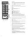
OPERATING INSTRUCTIONS
MEMORY CHECK AUTO
1
COOK
2
4.
MANUAL POWER
X2
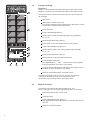
Manual operation
Manual operation is a method in which time and power can
be repeatedly adjusted depending on the type and
composition of the food which is being cooked.
X3
A
4.1
1-stage cooking
Example 1:
2 minutes 15 seconds cooking time with 50% power.
Open door.
B
Place plate or dish in the oven.
The food should be evenly distributed on the plate in
order to ensure a constant heating process.
Close the door.
Press "Manual/Repeat pad"(C).
Set the correct time using pads (B):"2","1","5".
C
D
F
E
Press Power Selection pad (F).
(If this pad is not pressed, the oven will work at full(100%)
power).
Press pad "5" in order to work with 50% power.
Press START button (E). The digital display continuously
displays the remaining cooking time.
Interrupting the cooking process
G
H
I
Opening the door will automatically interrupt the cooking
process. The digital display will display the remaining
cooking time. To continue cooking, close door and press
START button (E).
In order to select a new cooking time/power, press pad
"STOP" (D).
A signal will be heard at the end of the cooking process. It
will stop as soon as the door is opened.
Remove the food from the microwave oven.
In order to allow the oven to cool off, the fan will continue
running for another minute. Do not disconnect the
Microwave oven from the mains during this time.
6
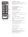
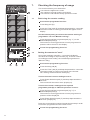
4.2
MEMORY CHECK AUTO
1
COOK
2
2-stage cooking
MANUAL POWER
X2
Example 2:
Stage 1: 5 minutes 30 seconds cooking time with 70% power..
Stage 2: 3 minutes 10 seconds cooking time with 50% power.
X3
A
This will result in a continuous cooking time of 8 minutes and
40 seconds.
Open door.
Place plate or dish in the oven.
The food would be evenly distributed on the plate in order
to ensure a constant heating process.
Close the door.
B
Press "Manual/Repeat"(C).
Set the time for the 1st cooking stage using pads (B):
"5","3","0".
Press Power Selection pad (F).
Press pad "7" in order to operate with 70% power.
Press "Manual/Repeat" pad (C).
C
D
Set the time for the 2nd cooking stage using pads (B)
"3","1","0".
F
E
Press Power Selection pad (F).
Press pad "5" to operate with 50% power.
G
H
Press START button (E).
The digital display
and
shows which cooking stage
of the programme is currently in progress.
I
A signal will be heard at the end of the cooking process. It
will stop as soon as the door is opened.
Remove the food from the microwave oven.
In order to allow the oven to cool off, the fan will continue
running for another minute. Do not disconnect the
microwave oven from the mains during this time.
4.3
Repeat function
For ease of use with the this Microwave Oven, the
same cooking process can be repeated as often as you wish.
Place the plate or dish in the oven.
Close the door.
Press "Manual/Repeat" pad (C).
The digital display will indicate the time/power which was
last set.
Press the "START" button.
7
MEMORY CHECK AUTO
1
COOK
2
5.
MANUAL POWER
X2
Programmed cooking
The programming function is automatically deactivated on
connecting the microwave oven to the mains.
The pads "Memory"(G),"Test"(H) und "Acoustic signal level" (I)
are inoperative.
X3
A
5.1
To activate the programme
1.
2.
3.
4.
5.
B
Close the door and press the Stop pad (D) twice.
Press Memory pad (G).
Press Start pad (E) twice.
Press the "0" pad.
Press Memory pad (G)
("MEMORY" will blink on the display).
The programming is now activated.
5.2
Deactivating the programme
1.Close the door and press the Stop pad (D) three times.
2.Press the pad "0".
C
The programming function is now cancelled. No information
can be programmed.
D
F
E
5.3
Using the Programme Memory
Up to 10 different cooking programmes can be stored in the
Memory.
It is possible to set 1 and 2 stage cooking in the Memory.
G
H
I
Example 1:
A 1-stage cooking programme using Memory space 1.
5 minutes cooking time with 70% power.
1. Activate the programming function.
2. Press the desired programme pad (B), in this instance "1".
3. Press "Manual/Repeat" pad (C).
4. Press pads "5","0","0".
5. Press Power Selection pad (F).
6. Press pad "7" for 70% power.
7. Press Memory pad (G).
To cancel a programming error, press Stop pad (D).
Then repeat steps 2-7.
In order to check whether a programme has been correctly
completed, press pad "Test" and then pad "1".
The programme set under this Memory space number
should appear on the display.
Cancel the programming function.
8
Example 2:
MEMORY CHECK AUTO
1
COOK
2
MANUAL POWER
X2
Set a 2-stage cooking programme in Memory space 2.
Stage 1: 5 minutes 30 seconds cooking time using 100%
Power.
Stage 2: 3 minutes 10 seconds cooking time using 10%
power.
X3
A
Active the programming function.
Press the Programme pad (B), in the present instance:"2".
Stage 1
Press "Manual/Repeat" pad (C).
Press pads "5", "3","0".
B
Stage 2
Press "Manual/Repeat" pad (C).
Press pads "3", "1","0".
Press Power Selection pad (F).
Press pad "1" for 10% power.
Press Memory pad (G).
Cancel the programming function.
In order to use the remaining 8 programming spaces, you
repeat the process for the One-stage and Two-stage
programme as described under the above two examples.
C
D
Used programme pads can simply be overwritten if required.
F
E
5.4
To use the programme function once the microwave has been
programmed follow the instructions below.
Open the door.
G
H
I
Put the food which is to be cooked in the microwave oven
and close the door.
By pressing the desired Programme pad (B) the cooking
process will immediately start up.
An acoustic signal will be given at the end of the cooking
process. The signal continues until the door is opened.
Remove the food from the microwave oven.
In order to allow the oven to cool off, the fan will continue
running for another minute. Do not disconnect the
Microwave oven from the mains during this time.
Interrupting the cooking process
Pressing the Stop pad (D) will interrupt the cooking process.
The remaining cooking time will be shown on the digital
display.
Close the door and press the Start pad (E) to continue the
cooking process.
Cancelling the cooking process
The cooking process will be automatically cancelled by
opening the door. The remaining cooking time is not shown
on the digital display. If you wish to continue select a NEW
PROGRAMME.
9
MEMORY CHECK AUTO
1
COOK
2
6.
MANUAL POWER
X2
x2 / x3 programmed cooking
The multiplication pads "x2" and "x3" are used when the
quantity of food placed in the oven exceeds twice or threetimes the portion specified in the programmed pads.
X3
A
Open the door.
Place the food in the microwave oven and close the door.
Press pad "x2" or "x3" (A).
Press the required programme pad (B).
An acoustic signal will sound at the end of the cooking
process and will continue until the door is opened.
B
Remove the food from the oven.
Should the required cooking time exceed the limit, "EE-1"
will be shown in the display. Hence it will not be possible to
cook the portion of food for that amount of time. Press the
Stop pad (4) and reduce the quantity of food which has been
placed in the oven.
Maximum cooking times for
1-stage cooking: 30minutes.
2-stage cooking: Power >
- 50%-15 min. Per stage.
Power <- 40%-30 min. Per stage.
C
D
F
E
6.1
Altering the pre-set x2 / x3
The standard setting of the multiplication pads
(x2=1.8 times / x3 =2.6 times) can, if desired,
Be changed for each of the Programme pads 1-0.
G
H
I
Example for Programme pad 1:
Change the "x2" pad from a 1.8 setting to a 1.5-times presetting.
1. Activate the programming function.
2. Press Start button (E).
3. Press "x2" pad.
4. Press "1" pad.
5. Press "Manual/Repeat" pad (C).
6. Press pads (B)"1","5" and "0".
7. Press Memory pad (G).
The new setting of the "x2" pad has been stored in the memory.
To check that the programming has been successfully
completed, press the "Test" pad and then pad "x2" and "1".
The x2-value set under this Memory space number should
appear on the display.
Cancel the programming function.
10
MEMORY CHECK AUTO
1
COOK
2
7.
MANUAL POWER
X2
Checking the frequency of usage
This function allows you to determine:
how often the appliance is used
the number of manual cooking processes
how often the individual memory spaces are used.
X3
A
7.1
Retrieving the counter reading
Activate the programme function.
Press Stop pad (D).
Press the "Test" pad (H) and keep depressed for 2 seconds.
The total number of cooking processes will appear on the
display.
B
In order subsequently to retrieve the counter reading of
programmes 1-0 and "Manual cooking":
Press the appropriate programme pad (eg. "1") or the
Manual/Repeat pad (C).
The number of cooking processes of each programme in
question will be shown on the display.
Cancel the programming function.
C
D
F
E
7.2
Setting the counter to "zero"
All counter readings quoted in 7.1 must be individually
cancelled according to requirements (eg. The total number
of cooking process weekly; the individual programmes or
"Manual" daily).
Activate the programming function.
G
H
I
Press the Stop pad (D).
Press the "Test" pad (H) and keep depressed for 2 seconds.
The total number of cooking processes since the last
zero-setting will be shown on the display.
To reset the total counter readings to zero:
Press Power Selection pad (F) and keep depressed for 2
seconds.
The counter will be reset to zero (display=0).
To reset the counter readings of the required
programme pads (B) or "Manual operation" to zero:
Press the appropriate programme pad (eg."1") or
Manual/Repeat pad (C).
The number of cooking processes of each programme in
question will be displayed.
Press Power Selection pad (F) and keep depressed for 2
seconds. (Display=0).
Press the corresponding pad and repeat the last step in order
to set other programme counters back to zero.
Cancel the programming function.
11
MEMORY CHECK AUTO
1
COOK
2
8.
MANUAL POWER
X2
Setting the acoustic signal
Activate the programming function.
Press Stop pad (D).
Press "sound level" (I) until the required acoustic level is
obtained.
Press Memory pad (G).
Cancel the programming function.
X3
A
B
C
D
F
E
G
H
I
9.
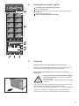
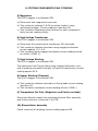
Cleaning
Always remove the mains plug before cleaning!
Remove any spilt food immediately using a damp sponge or
cloth which has been dipped in a mild detergent.
Never use harsh abrasives or scourers for cleaning
purposes.
!
The whole oven area should be thoroughly
cleaned once daily to prevent the appliance
malfunctioning.
The door seals in particular should be carefully
cleaned.
The air filter which is located directly below the door must be
removed and cleaned once a week with hot water.
Do not forget to re-install the filter prior to using the appliance.
Clean the outside of the appliance with a chrome-nickelsteel cleaner of a type recommended by the manufacturer.
12
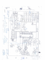
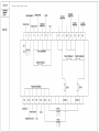
6 WIRING DIAGRAM OVEN
7 WIRING DIAGRAM RELAY BOARD
8) DESCRIPTION OF OPERATION INCLUDING
DOOR SWITCH OPERATION
a) Sequence of circuit.
Refer to wiring diagrams to follow sequence of operation.
When switched supply is connected 240V enters via special 15A fuse
through the noise filter/suppressor to PCB terminal C4, both
magnetron thermal cut outs (120°C), cavity thermal cut out (160°C)
to terminal CN1 on main PCB assembly. Neutral is via noise
filter/suppressor to terminal CN2 on main PCB.CN1 & CN2 supply the
low voltage transformer and machine now powers up. The display
colon illuminates and if the door is opened and closed Relay 3 will
close which will supply 240V to the fan, oven lamp and 2 pairs of 390Ω
soft start resistors via the door switches. These resistors drop the
240V down to approx 160/ 170V before supplying the high voltage
transformers which as a result, produce insufficient high voltage to
switch on the magnetrons. After 60 seconds relay 3 will de-energise if
the machine is not operated and only the display colon will remain
illuminated.
Opening the door will interrupt the supply to the soft start resistors &
high voltage transformers (when relay 3 is energised) via primary and
secondary door switches (normally open contacts).
When the machine is programmed and started relays 5 & 6 operate
and short circuit both pairs of gold resistors there-by allowing full
voltage to the high voltage transformers via the relay board 10A fuses
and terminals CNF1 & CNF2.Lower power operation is controlled by
switching of relays 5 &/or 6.
b) Door Switch Operation
The door switch system is designed to isolate the supply from the high
voltage transformers whenever the door is not fully closed. It is also
designed to fail-safe should contacts on the switch’s fail or levers
become obstructed with food, dust, debris etc.
When the oven door is closed the first switch to operate is the monitor
switch (normally closed contacts) whose contacts open. This is
followed by the primary and secondary interlock switches(normally
open contacts) closing, together with the door sensing switch(normally
open contacts ) to activate the control system. From the wiring
diagram it can be seen that failure to follow this sequence will result in
a short circuit through the monitor switch causing the special 15A fuse
to fail. When the door is opened the switch sequence is reversed. Door
sensing, secondary and primary interlock switches operate first to
isolate supply to the high voltage transformers followed by the monitor
switch which closes its contacts. Again if sequence is incorrect the 15A
fuse will fail. Should the 15A fuse fail due to operation of the monitor
interlock circuit, primary, secondary and monitor switches should all be
replaced.
8) DESCRIPTION OF OPERATION INCLUDING
DOOR SWITCH OPERATION
c) High Voltage Circuit Operation
Each microwave circuit consists of a magnetron and a voltage doubler
circuit. The voltage doubler consists of a special step-up transformer, a
capacitor and a diode. See diagram for an explanation of how the
doubler works.
9) TESTING COMPONENTS/FAULT FINDING
WARNING
NO HIGH VOLTAGE MEASUREMENTS SHOULD BE ATTEMPTED
DISCHARGE THE HIGH VOLTAGE CAPACITOR BEFORE
TESTING PROCEDURES ARE CARRIED OUT.
THE FOLLOWING TESTS ARE ALL CARRIED OUT WITH THE
OVEN ISOLATED FROM MAINS SUPPLY.
1) Membrane Key Assembly
Refer to wiring diagram (Section 7, 2).
Tool multimeter.
a) Unplug membrane from PCB control.
b) Test for continuity between correct terminals when pads pressed.
2) High Voltage Rectifier ( Doubler Diode)
Tool 500V megger or multimeter R9V
a) Disconnect from HV capacitor.
b) Measure continuity in both directions conducts one way only,
infinite resistance the other. Diode is good.
3) Asymmetric Diode Assembly ( Protector Diode)
Tool 500V megger or multimeter R9V
a) Disconnect from HV capacitor.
b) Measure continuity in both directions. Infinite resistance both
ways Asymmetric Diode Good.
4) High Voltage Capacitor DISCONNECT ALL CONNECTIONS
Tool 500V megger or multimeter R9V
a) Test continuity between terminals using multimeter/megger.
Reading should show some continuity initially then as capacitor
charges resistance increases to approx. 10MΩ (leakage resistor
as fitted).
b) Test insulation resistance each terminal to earth (casing) using
megger/multimeter the reading should be infinite (10MΩ +).
9) TESTING COMPONENTS/FAULT FINDING
5) Magnetron
Tool 500V megger or multimeter R9V
a) Disconnect both magnetron terminals.
b) Test continuity between F & FA terminals (heater) using
multimeter/megger. Correct reading is less than 1Ω.
c) Test insulation resistance either terminal to earth (magnetron
body) correct reading infinity.
6) High Voltage Transformer
Tool 500V megger or multimeter R9V
a) Disconnect all connections to transformer 240 terminals.
b) Test continuity between terminals using megger/multimeter
correct reading 1.2-1.4 Ω.
c) Test insulation using megger/multimeter correct reading should
be infinite (10MΩ +).
7) High Voltage Winding
Tool 500V megger or multimeter R9V
Test continuity from Tag to frame using megger/multimeter (one
end of winding connected internally to frame of transformer) correct
reading approx 80 Ω.
8) Heater Winding (Filament)
Tool 500V megger or multimeter R9V
a) Test continuity between terminals on flying leads correct reading
less than 1Ω.
b) Test insulation resistance correct reading infinite (10MΩ+)
9) Temperature Cut Outs (Magnetron and Cavity overheat)
Disconnect Neutral output from suppressors/noise filter assembly
and check continuity to terminal 1 on PCB.
10) Blower Motor Assembly
Check continuity of windings correct reading approx 60Ω.
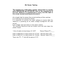
10) Power Testing
This machine is rated with a power output test to comply
with BSEN60335 and IEC60705. Due to the complexity of
the test method it is impractical to carry out this test in
the ovens normal working environment.
As a simple test to assess the correct working of the machine
It is sufficient to proceed as follows.
It is essential to monitor the input voltage to ensure that the
machine is operating at its rated voltage throughout the test
period.
Low voltage input will result in low power output.
The machine should be cold as a warm oven will also lower the
power output
1 litre of water at start temp 10-16°C
Heat in AWI180T on high power for 27 secs
Heat in AWI140T on high power for 33 secs
Temp rise T2 – T1 should be approx 10°C
Record Temp (T1)____
Record Temp (T2)____
Record Temp (T2)____
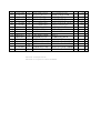
11 EXPLODED VIEW
REPORT NAME: SAMPO CORPRATION PARTS LIST
MODEL: AWI-180T
PRODUCT: V
SERI
FIG.
01
02
03
04
05
06
07
08
09
10
11
12
13
14
15
16
17
18
19
20
21
21-1
21-2
22
23
24
25
26
27
28
29
30
31
32
33
34
35
36
37
NUMBER:
CUSTOM: AWI-UK
EXCHANGE(NT/US):
MOD
PAGE :
FILE NAME:
RELEASE DATE:2005.07.25
VERSION
(US)
ENG_ID NOP. ART NONGLISH DESCRIPTIO
COL
QTY FOB/PC SH
VC120 014
13 LSTP-0007V2-0-GUIDE FOR HANDLE
4
0.08 A
1.07 B
VC120 008
52 JHNDM0163V2F0-- OUTER HANDLE
1
VC120 009
53 JHNDM0164V2F0Y- INTER HANDLE
3.75 A
1
VC120 007
89 HDECM0007V2P0-- MASK OF DOOR
1
7.71
2
0.16 A
VC120 010
75 LANGF0625V2-0-DOOR GLASS HOLDER
3.21 A
VC120 022
22 PGLS-0010V2-0-OUTER GLASS OF DOOR 1
VC120 001
60 GMSKM0008V2T0-- FRAME OF DOOR
1 10.92 A
VC120 011
76 LANGF0630V2P0-- LATCH HOOK SUPPORT
1
0.7 A
1.02 A
VC120 017
38 MLOK-0022V2-0Y- LATCH HOOK
1
VC120 016
38 MLNKM0005V2P0-1 LINK
1
0.53 A
VC120 018
23 MSPR-0038V2-0-A
SPRING
1
0.16 A
1.02 A
VC120 017
38 MLOK-0022V2-0Y- LATCH HOOK
1
VC120 015
40 MLEV-0022V2-0-LEVER OF DOOR
1
0.15 A
VC120 012
55 LANGF0631V2P0-- UP/DOWN HINGE
2
0.36 A
VC120 023
89 PGLS-0016V2-0-INTER GLASS OF DOOR
1
3.34 A
VC120 019
62 PCOVZ0073V2-0-C DOOR COVER
1
3.24 A
VC140 002
65 HDECM0008V2P0-Y SUS PANEL MASK
1
2.05 A
TOUCH
PAD
VC140 007
34 QCTPB1046V2-0-1 10.23 B
VC140 003
85 HDECP0279V2F0-- DISPLAY COVER
1
0.2 A
VC140 004
5
HPNLC0162V2F0-C CONTRAL PANEL
1
1.46 A
VC140 001
49 CPWB-0763V2-0Y1 CONTROL UNIT
1 33.67 B
VD140 001
42 RRLYD1105V2P0M- RELAY
3
1.69 B
C.P.U
VD140 002
51 VSI65404A4805Y1
6.03 B
VC140 005
3
LANGF0632V2P0-1 PANEL SUPPORT
1
0.24 A
VC160 013
1
PGLS-0011V2-0-GLASS TRAY
1
21.7 B
VC195 003
19 NSFTP0013V2-0-SHAFT OF MICA
1
0.13 A
VC195 002
37 NSFTP0012V2-0-SHAFT OF STIRRER
1
0.13 A
VC195 006
74 LSTYP0068V2-0-1
TEFLON WASHER
2
0.11 A
VC195 004
70 PSLD-0009V2-0-MICA PLATE
1
4.03 A
VC195 001
88 NMIX-0003V2-0-A
STIRRER
1
1.02 A
0.37 A
VB100 004
45 LHLD-0218V2-0YHOLDER FOR DECORAT I 1
VB100 002
53 HDECM0009V2P0-- UP DECORATION
1
2.17 A
VC130 002
10 GNETM0035V2T0-- AIR NET
1
1.54 A
VC100 001
77 LCHSM0033V2T0-B CHASSIS
1
7.08 A
VC100 003
60 RPT-J1338-1--OB
H.V.TRANSFORMER
2 27.79 B
VC140 013
28 CPWB-0833V2-0Y- START BOARD
1
1.41 B
VC140 028
58 QFS-J103SV220Y10A FUSE
2
0.2 B
OVEN
CAVITY
VC160 012
40 GOVN-0008V2K0-H
1 43.79 A
VB100 022
15 PSHD-0013V2-0-FILM FOR LAMP
1
0.06 A
37
38
39
40
41
42
43
44
45
46
48
47
49
50
51
52
53
54
55
56
57
58
59
60
61
62
63
64
65
68
71
72
73
74
75
76
77
78
79
80
81
82
83
84
VC140
VC130
VC130
VB100
VC130
VB100
VB100
VC130
VB200
VB200
VB100
VC130
VC130
VC130
VB100
VC180
VC180
VC180
VC180
VC180
VC190
VC190
VC190
VB100
VB100
VB100
VC130
VB100
VC150
VC150
VC150
VC150
VC150
VC150
VC150
VB100
VC190
VC190
VB400
VB100
VC130
VC130
VC130
VD140
006
024
023
003
020
060
061
001
001
003
005
018
022
008
028
001
011
010
009
007
001
002
007
001
029
020
019
010
003
008
004
006
010
011
012
023
011
008
002
042
010
009
003
003
15
76
51
41
71
47
82
76
77
10
27
76
5
7
43
34
1
72
49
25
13
7
38
45
15
69
34
60
23
22
36
18
59
38
70
14
53
23
70
55
26
43
62
62
PSHD-0013V2-0-RLMPN1017-1---QSOCL1008-102-LANGF0636V2-0-PGID-0026V2F0-1
CPWB-0765V2-0YDWPB-0514V2-0YGCOV-0011V2P0-GCABM0008V2P0-A
PDUC-0001V2P0-A
LHLD-0219V2-0YPGID-0024V2P0-2
RFILN0004V2-0YLANGF0742V2P0-RTHM-1009-1NZ-RMOTA1120-1FVY1
LANGF0634V2P0-LANGF0635V2P0-NFANS0001V2-0-PDUC-0002V2F0-LANGF0654V2-0-A
LANGF0728V2-0-RC-EZ0073V2-0YGCABB0173V2P0-B
VVM2M244-M62J1PGID-0023V2P0-PGID-0025V2F0-LPLT-0005V2-0-LHLD-0506V2F0-MSPR-1063V2-0-MLEV-0023V2F0-MLEV-0024V2F0-QSW-M1020-11-1B
QSW-M1021-11-1B
QSW-M1017V2-0-C
QACC-1015V2-0-RC-EZ1167V2-0YVSDHVR32B062H-PCUSU0101V2-0-DDOR-0236V2K0-1
QFSHB1030-1-U-QFS-A153NV220YQFSH-0002V2-0-VVKFV518GN-----
FILM FOR LAMP
1
0.06 A
LAMP
1
0.49 A
LAMPHOLDER
1
0.34 A
LAMP FRAME
1
0.25 A
AIR DUCT
1
0.79 A
THERMISTOR BOARD
2.43 A
TEMPERATIRE FUSE BOARD 0.85 A
LAMP COVER
1
0.52 A
CABIENT
1 22.38 A
AIR DUCT
1
0.56 A
0.37 A
HOLDER FOR DECORAT I 1
UP AIR DUCT
1
1.06 A
NOISE FILTER
1
3.83 B
FRAME OF FILTER
1
0.5 B
THERMOSTAT
2
1.23 B
FAN MOTOR
1 16.85 B
MOTOR SUPPORT
1
0.76 A
AIR DUCT COVER
1
0.36 A
FAN
1
0.53 B
1.02 A
DUCT FOR COOLING FA N 1
CAPACITOR FRAME
1
0.74 A
CAPAUTOR HOLDER
1
0.37 A
H.V.CAPACITOR
1
2.64 B
BACK PLATE
1
2.63 A
MAGNETRON
2 27.47 B
DUCT FOR MGT
1
0.24 A
DUCT
1
0.76 A
DUCT COVER
1
1.18 A
SWITCH HOLDER
1
0.95 A
SPRING
1
0.07 A
1
0.18 A
UPPER LEVEL
LOWER LEVEL
1
0.19 A
MICRO SWITCH
3
0.38 B
MICRO SWITCH
1
0.38 B
MICRO SWITCH
1
0.38 B
PWOER CORD
1
3.04 B
H.V.CAPACITOR
1
2.71 B
H.V.DIODE
2
2.49 B
CUSHION
0.1
ASSEMBLY DOOR UNIT
1
25 D
FUSE HOLDER
0.5 B
1
15A FUSE
1
0.72 B
RESISTOR
2
2.59 A
DISPLAY
1
8.53 B
85
86
87
88
89
90
91
92
93
94
95
96
97
98
99
100
VB200 004
VC180 012
VC130 005
VC130 004
VC130 006
VC130 007
VB400 002
VB400 002
VB100 006
VB100 011
VB100 021
VB100 064
VC190 003
VC190 004
VC190 005
VC190 006
31
10
33
85
70
52
48
63
48
34
56
30
23
84
29
1
PFPFL0007V2P0-A
RC-EZ1128V2-0-LANG-0110V2P0-LANG-0109V2P0-LX-LZ0005V2N0-LX-LZ0006V2N0-SPAKC05384V2R0-TINSE1867V2-0-LHLDK0031V2-0-LX-LZ0007V2N0-PISLM0012V2-0-LBSH-0018V2-0-QTIPW1035-1162B
QTIPW1035-1163B
QTIPW1035-1164QTIPW1035-1165-
HEAT INSULATER
NOISE CAPACITOR
GUIDE PLATE (1)
GUIDE PLATE (2)
BLQCKADE FOR AIR IN L
SCREW FOR INLET
PACKING CASE
OPERATION MANUAL
STOP CORD
RIVET
STIRRER STOPER
FUSE COVER
HIGH VLOTAGE WIRING
HIGH VLOTAGE WIRING
HIGH VLOTAGE WIRING
HIGH VLOTAGE WIRING
AWI140T Touchpad TP140
AWI140T HV Capacitor 85uf 2500WVAC
1
1
1
1
2
2
1
1
1
1
1
1
1
1
1
1
2.52
0.21
0.35
0.21
0.07
0.06
A
B
A
A
A
A
A
A
A
A
A
A
A
A
A
A