1
YAMAHA SINGLE-AXIS ROBOT DRIVER
RD series
User’s Manual
ENGLISH
E
YAMAHA MOTOR CO., LTD.
IM Operations
882 Soude, Naka-ku, Hamamatsu, Shizuoka 435-0054.Japan
URL http://www.yamaha-motor.jp/robot/index.html
E97-Ver. 2.05
Note to the user
Our sincere thanks for purchasing this "YAMAHA single-axis robot driver RD series".
This user's manual describes handling and maintenance of the RD series. Read this
manual thoroughly before using the RD series. Keep this manual handy so that the
operator or maintenance personnel can easily refer to it when needed.
Before starting installation, operation, maintenance or inspection, read this manual
carefully to understand RD series functions and comply with its safety information,
precautions, and operating and handling instructions.
Always use the RD series within the operation range specified in this manual.
Perform correct inspection and maintenance to prevent possible problems.
When using optional products for this robot driver also be sure to carefully read their
instruction manuals.
Please make sure this user's manual and option product manuals are delivered to the end
user.
About this manual
• The contents of this manual are subject to change without prior notice.
• Carefully keep this manual because it will not be reissued.
• This manual must not be reproduced or reprinted in part or in whole without our
permission.
• Every effort was made to ensure that this manual is accurate and complete.
However, please contact us if you notice any errors, omissions or dubious points.
Please note that we accept no responsibility for any results that might occur from use
of this manual or the unit described in it.
MEMO
General Contents
Chapter 1
Safety precautions
1.1
Precautions for use
1-1
1.2
Storage
1-2
1.3
Carrying
1-3
1.4
Installation
1-3
1.5
Wiring
1-4
1.6
Control and operation
1-5
1.7
Maintenance and inspection
1-6
Chapter 2
2.1
Before using the unit
Inspection after unpacking
2.1.1 Checking the product
2.1.2 User's manual
2.2
Product inquiries and warranty
2.2.1 Notes when making an inquiry
2.2.2 Warranty
2-1
2-1
2-2
2-3
2-3
2-3
2.3
External view and part names
2-4
2.4
Robot driver and robot combination
2-5
Chapter 3
3.1
Installation and wiring
Installation
3.1.1 Precautions during installation
3-1
3-2
3.2
Wiring
3-4
3.2.1
3.2.2
3.2.3
3.2.4
3.2.5
Terminal block and connectors
Main circuit wiring
Wiring to the control terminal block (TM2)
Input/output signal wiring
Wiring for position sensor signals
3-4
3-5
3-13
3-14
3-27
Chapter 4
4.1
Operation
Control and operation
4.1.1 Position control by pulse train input
4.2
Test Run
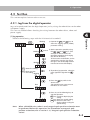
4.2.1 Jog from the digital operator
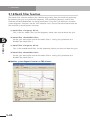
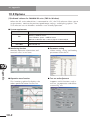
4.2.2 Making a test run using "TOP" software for RD series
4.3
Emergency stop
Chapter 5
4-1
4-2
4-3
4-3
4-4
4-6
Functions
5.1
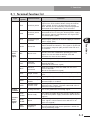
Terminal function list
5-1
5.2
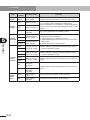
Input terminal functions
5-3
5.3
Output terminal functions
5.4
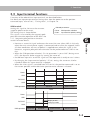
Return-to-origin function
5-10
5.5
Analog output function
5-21
5.6
Pulse train input function
5-22
5.7
Smoothing function
5-25
5.8
Position sensor monitor function
5-26
5.9
Adjusting the control gain
5-27
5.9.1 Basic rules of gain adjustment
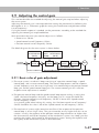
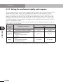
5.9.2 Setting the mechanical rigidity and response
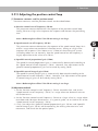
5.9.3 Adjusting the position control loop
5.10 Offline auto-tuning function
5.10.1 Offline auto-tuning method
5.10.2 Offline auto-tuning using the TOP software
5-7
5-27
5-28
5-29
5-30
5-30
5-33
5.11 Gain change function
5-35
5.11.1 Changing the control gain
5-35
5.12 Clearing the alarm log and setting the default values
5-38
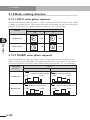
5.13 Motor rotating direction
5-40
5.13.1 FLIP-X series phase sequence
5.13.2 PHASER series phase sequence
5-40
5-40
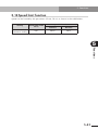
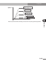
5.14 Speed limit function
5-41
5.15 Fast positioning function
5-42
5.16 Notch filter function
5-44
5.17 Magnetic pole position estimation action
5-45
5.18 Magnetic pole position estimation and parameters
5-46
Chapter 6
6.1
Parameter description
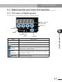
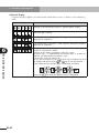
Digital operator part names and operation
6.1.1 Part names of digital operator
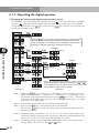
6.1.2 Operating the digital operator
6.2
Function lists
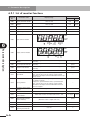
6.2.1 List of monitor functions
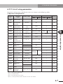
6.2.2 List of setup parameters
6.3
Function description
6-1
6-1
6-2
6-5
6-6
6-7
6-12
6.3.1 Monitor display description
6-12
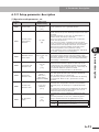
6.3.2 Setup parameter description
6-15
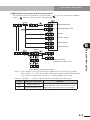
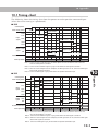
6.3.3 Reference graph for setting the acceleration and position
control cut-off frequency
6-32
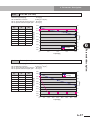
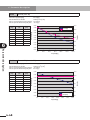
■ RDX …………………………………………………………………………… 6-33
T4H-2 (C4H-2) ……………………………………………………………………… 6-33
T4H-2-BK (C4H-2-BK) ……………………………………………………………… 6-33
T4H-6 (C4H-6) ………………………………………………………………………
T4H-6-BK (C4H-6-BK) ………………………………………………………………
T4H-12 (C4H-12)……………………………………………………………………
T4H-12-BK (C4H-12-BK)……………………………………………………………
T5H-6 (C5H-6) ………………………………………………………………………
T5H-6-BK (C5H-6-BK) ………………………………………………………………
T5H-12 (C5H-12)……………………………………………………………………
T5H-12-BK (C5H-12-BK)……………………………………………………………
T5H-20 ………………………………………………………………………………
T6-6 (C6-6) …………………………………………………………………………
T6-6-BK (C6-6-BK) …………………………………………………………………
T6-12 (C6-12) ………………………………………………………………………
T6-12-BK (C6-12-BK) ………………………………………………………………
T6-20 …………………………………………………………………………………
T7-12 …………………………………………………………………………………
T7-12-BK ……………………………………………………………………………
T9-5 …………………………………………………………………………………
T9-5-BK ………………………………………………………………………………
T9-10 …………………………………………………………………………………
T9-10-BK ……………………………………………………………………………
T9-20 …………………………………………………………………………………
T9-20-BK ……………………………………………………………………………
T9-30 …………………………………………………………………………………
T9H-5 …………………………………………………………………………………
T9H-5-BK ……………………………………………………………………………
T9H-10 ………………………………………………………………………………
T9H-10-BK……………………………………………………………………………
T9H-20 ………………………………………………………………………………
T9H-20-BK……………………………………………………………………………
T9H-30 ………………………………………………………………………………
F8-6 (C8-6) …………………………………………………………………………
F8-6-BK (C8-6-BK) …………………………………………………………………
F8-12 (C8-12) ………………………………………………………………………
F8-12-BK (C8-12-BK) ………………………………………………………………
F8-20 (C8-20) ………………………………………………………………………
F8L-5 (C8L-5) ………………………………………………………………………
F8L-5-BK (C8L-5-BK) ………………………………………………………………
F8L-10 (C8L-10) ……………………………………………………………………
F8L-10-BK (C8L-10-BK) ……………………………………………………………
F8L-20 (C8L-20) ……………………………………………………………………
F8L-20-BK (C8L-20-BK) ……………………………………………………………
F8L-30 ………………………………………………………………………………
F8LH-5 (C8LH-5) ……………………………………………………………………
F8LH-10 (C8LH-10) …………………………………………………………………
F8LH-20 (C8LH-20) …………………………………………………………………
F10-5 (C10-5) ………………………………………………………………………
F10-5-BK (C10-5-BK) ………………………………………………………………
F10-10 (C10-10) ……………………………………………………………………
F10-10-BK (C10-10-BK) ……………………………………………………………
F10-20 (C10-20) ……………………………………………………………………
F10-20-BK (C10-20-BK) ……………………………………………………………
F10-30 ………………………………………………………………………………
F14-5 (C14-5) ………………………………………………………………………
F14-5-BK (C14-5-BK) ………………………………………………………………
F14-10 (C14-10) ……………………………………………………………………
F14-10-BK (C14-10-BK) ……………………………………………………………
6-34
6-34
6-35
6-35
6-36
6-36
6-37
6-37
6-38
6-38
6-39
6-39
6-40
6-40
6-41
6-41
6-42
6-42
6-43
6-43
6-44
6-44
6-45
6-45
6-46
6-46
6-47
6-47
6-48
6-48
6-49
6-49
6-50
6-50
6-51
6-51
6-52
6-52
6-53
6-53
6-54
6-54
6-55
6-55
6-56
6-56
6-57
6-57
6-58
6-58
6-59
6-59
6-60
6-60
6-61
6-61
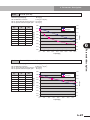
F14-20 (C14-20) ……………………………………………………………………
F14-20-BK (C14-20-BK) ……………………………………………………………
F14-30 ………………………………………………………………………………
F14H-5 (C14H-5) …………………………………………………………………
F14H-5-BK (C14H-5-BK) …………………………………………………………
F14H-10 (C14H-10) ………………………………………………………………
F14H-10-BK (C14H-10-BK) ………………………………………………………
F14H-20 (C14H-20) ………………………………………………………………
F14H-20-BK (C14H-20-BK) ………………………………………………………
F14H-30 ……………………………………………………………………………
F17L-50 (C17L-50) …………………………………………………………………
F17L-50-BK (C17L-50-BK) …………………………………………………………
F17-10 (C17-10) ……………………………………………………………………
F17-10-BK (C17-10-BK) ……………………………………………………………
F17-20 (C17-20) ……………………………………………………………………
F17-20-BK (C17-20-BK) ……………………………………………………………
F17-40 ………………………………………………………………………………
F20-10-BK (C20-10-BK) ……………………………………………………………
F20-20 (C20-20) ……………………………………………………………………
F20-20-BK (C20-20-BK) ……………………………………………………………
F20-40 ………………………………………………………………………………
F20N-20 ……………………………………………………………………………
N15-10 ………………………………………………………………………………
N15-20 ………………………………………………………………………………
N15-30 ………………………………………………………………………………
N18-20 ………………………………………………………………………………
B10 …………………………………………………………………………………
B14 …………………………………………………………………………………
B14H …………………………………………………………………………………
R5 ……………………………………………………………………………………
R10 …………………………………………………………………………………
R20 …………………………………………………………………………………
■ RDP ……………………………………………………………………………
MR12…………………………………………………………………………………
MR16…………………………………………………………………………………
MR16H ………………………………………………………………………………
MR20…………………………………………………………………………………
MR25…………………………………………………………………………………
MF7 …………………………………………………………………………………
MF15 …………………………………………………………………………………
MF20 …………………………………………………………………………………
MF30 …………………………………………………………………………………
MF50 …………………………………………………………………………………
MF75 …………………………………………………………………………………
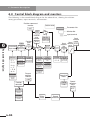
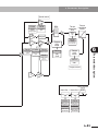
6.4
Control block diagram and monitors
Chapter 7
6-62
6-62
6-63
6-63
6-64
6-64
6-65
6-65
6-66
6-66
6-67
6-67
6-68
6-68
6-69
6-69
6-70
6-70
6-71
6-71
6-72
6-72
6-73
6-73
6-74
6-74
6-75
6-75
6-76
6-76
6-77
6-77
6-78
6-78
6-78
6-79
6-79
6-80
6-80
6-81
6-81
6-82
6-82
6-83
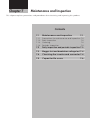
6-84
Maintenance and Inspection
7.1
Maintenance and inspection
7.1.1
7.1.2
7.1.3
7.1.4
Precautions for maintenance and inspection
Daily inspection
Cleaning
Periodic inspection
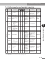
7.2
Daily inspection and periodic inspection
7-1
7-2
7-2
7-2
7-2
7-3
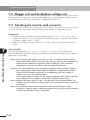
7.3
Megger test and breakdown voltage test
7-4
7.4
Checking the inverter and converter
7-4
7.5
Capacitor life curve
7-6
Chapter 8
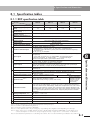
8.1
Specifications and Dimensions
Specification tables
8.1.1 RDP specification table
8.1.2 RDX specification table
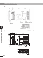
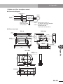
8.2
Robot driver dimensions and mounting holes
Chapter 9
8-1
8-1
8-2
8-3
Troubleshooting
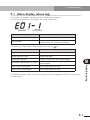
9.1
Alarm display (alarm log)
9-1
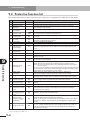
9.2
Protective function list
9-2
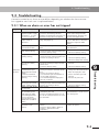
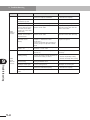
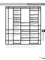
9.3
Troubleshooting
9-3
9.3.1 When an alarm or error has not tripped
9.3.2 When an alarm or error has tripped
Chapter 10
9-3
9-5
Appendix
10.1 Timing chart
10-1
10.2 Options
10-2
10.3 Recommended peripheral devices
10-7
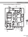
10.4 Internal block diagram of robot driver
10-13
Chapter 1
Safety precautions
To use this unit correctly and safely, always read this manual and all other attached documents
carefully before use. Use this unit only after you are thoroughly familiar with its features and
functions, safety information and precautions.
Contents
1.1
Precautions for use
1-1
1.2
Storage
1-2
1.3
Carrying
1-3
1.4
Installation
1-3
1.5
Wiring
1-4
1.6
Control and operation
1-5
1.7
Maintenance and inspection
1-6
1. Safety precautions
To use this unit correctly and safely, always read this manual and all other attached
documents carefully before use. Use this unit only after you are thoroughly familiar with
its features and functions, safety information and precautions.
w
c
DANGER
INDICATES AN IMMINENTLY HAZARDOUS SITUATION WHICH, IF NOT AVOIDED,
WILL RESULT IN DEATH OR SERIOUS INJURY.
CAUTION
Indicates a potentially hazardous situation which, if not avoided, could result in
minor or moderate injury or damage to the equipment or software.
Note that some items described with "CAUTION" might lead to serious results depending
on the situation. In any case, always observe the above instructions and precautions
since they provide important safety information.
After reading this manual, always store it where the operator can easily refer to it any
time when needed.
Symbols used to indicate a prohibited or mandatory action are explained below.
: Indicates a prohibited action. For example,
indicates "Open flames prohibited
: Indicates a mandatory action. For example,
grounded.
indicates "Must be electrically
1.1 Precautions for use
w
DANGER
IMPROPER HANDLING MAY CAUSE ELECTRICAL SHOCK OR FIRE. ALWAYS OBSERVE
THE FOLLOWING PRECAUTIONS.
1. NEVER TOUCH ANY PART INSIDE THE ROBOT DRIVER.
TOUCHING PARTS MAY CAUSE ELECTRICAL SHOCK OR FIRE.
2. ALWAYS GROUND THE GROUND TERMINAL ON THE ROBOT DRIVER AND
ROBOT.
FAILURE TO DO SO MAY CAUSE ELECTRICAL SHOCK.
3. BEFORE MAKING WIRING CONNECTIONS OR INSPECTION, WAIT AT LEAST 10
MINUTES AFTER TURNING POWER OFF AND MAKE SURE THE CHARGE LAMP ON
THE FRONT PANEL IS OFF.
FAILURE TO DO SO MAY CAUSE ELECTRICAL SHOCK.
4. DO NOT DAMAGE THE CABLES OR APPLY EXCESSIVE STRESS TO THEM. DO NOT
PLACE HEAVY OBJECTS ON THE CABLES OR CRUSH THEM.
USING A DAMAGED CABLE MAY CAUSE ELECTRICAL SHOCK.
5. NEVER TOUCH A MOVING PART OF THE ROBOT DURING OPERATION.
DOING SO MAY CAUSE INJURY.
1-1
1
Safety precautions
This manual classifies safety caution items into the following alert levels, using the signal
words "DANGER" and "CAUTION".
1. Safety precautions
c
1
Safety precautions
CAUTION
1. Use only the specified robot and controller combination.
Using the wrong combination may cause fire or malfunction.
2. Never use this unit in locations subject to water, grinding fluid mist, corrosive
gases, explosive gases or salt damage. Do not use near inflammable
objects or materials.
Doing so may cause fire, malfunction or accidents.
3. The robot driver, robot and peripheral equipment may become hot during
operation. Be careful not to touch them.
Touching them may cause burns.
4. The robot driver's heat-sink fins, regenerative resistor, and robot may
become hot when power is being supplied or shortly after power is turned
off, so do not touch them.
Touching them may cause burns.
5. Allow at least a 5-minute time interval between power on and off.
Failure to do so may cause fire.
6. Install a leakage breaker on the power supply side of the robot driver.
Failure to do so may cause fire.
7. Use a power line, leakage breakers and electromagnetic contacts that
meet the required specifications (ratings).
Failure to do so may cause fire.
8. Do not start/stop operation by turning on or off the electromagnetic contact
installed on the power supply side of the robot driver.
Doing so may cause fire.
1.2 Storage
PROHIBITED
DO NOT STORE THE UNIT IN LOCATIONS EXPOSED TO RAIN, WATER DROPLETS,
GRINDING FLUID MIST OR HARMFUL GASES OR LIQUIDS.
MANDATORY
1. STORE THE UNIT IN LOCATIONS NOT EXPOSED TO DIRECT SUNLIGHT AND
WITHIN THE SPECIFIED HUMIDITY AND TEMPERATURE RANGE (–10 TO +70°C,
20 TO 90% RH WITHOUT CONDENSATION).
2. CONSULT WITH OUR COMPANY IF YOU HAVE STORED THE UNIT OVER AN
EXTENDED PERIOD OF TIME.
1-2
1. Safety precautions
1.3 Carr ying
c
1
Safety precautions
CAUTION
1. Do not carry the robot driver by the cables.
Doing so may cause malfunction or injury.
2. Do not carry the unit by the top cover or by the main circuit terminal block
cover.
Doing so may cause the unit to fall resulting in injury.
MANDATORY
LOAD THE UNITS CORRECTLY AS INDICATED. STACKING TOO MANY UNITS MAY
CAUSE THEM TO FALL OVER.
1.4 Installation
c
CAUTION
1. Do not step or stand on the unit. Do not place heavy objects on the unit.
Doing so may cause injury.
2. Do not block the air intake and exhaust vents. Do not allow foreign matter
or debris to penetrate inside.
Doing so may cause fire.
3. Always use the correct method to install the unit.
The unit may malfunction if not properly installed.
4. Install the robot driver on a straight, vertical wall not subject to vibration.
The unit may fall and injure someone if not properly installed.
5. Install the unit on a surface made of incombustible materials such as metal.
Failure to do so may cause fire.
6. Install the unit at a place strong enough to support the weight of the unit.
The unit may fall and injure someone if not properly installed.
7. Tighten the screws to the specified torque. Make sure that all screws are
securely fastened before operation.
The unit may fall and injure someone if not properly installed.
8. Provide the specified clearance between the robot driver and the inner
surface of the control panel or any other unit.
Failure to do so may cause malfunction.
9. Do not allow foreign matter such as cut wire fragments, welding debris, iron
waste or similar items to penetrate inside.
Doing so may cause fire.
10. Avoid applying strong shock to the unit to prevent malfunction.
11. Do not install the unit if any part is damaged or missing.
Doing so may cause fire or injury.
1-3
1. Safety precautions
1.5 Wiring
1
w
Safety precautions
c
1-4
DANGER
1. WIRING WORK SHOULD BE CARRIED OUT BY QUALIFIED ELECTRICIANS.
IMPROPER WIRING MAY CAUSE ELECTRICAL SHOCK OR FIRE.
2. ALWAYS FIRST INSTALL THE UNIT BEFORE CARRYING OUT WIRING.
FAILURE TO DO SO MAY CAUSE ELECTRICAL SHOCK OR INJURY.
3. MAKE SURE THE POWER IS OFF BEFORE CARRYING OUT WIRING.
FAILURE TO DO SO MAY CAUSE ELECTRICAL SHOCK OR FIRE.
4. BE SURE TO CONNECT THE ROBOT DRIVER'S GROUND TERMINAL TO THE
GROUNDING POINT (CLASS D: 100 OHMS OR LESS).
FAILURE TO DO SO MAY CAUSE ELECTRICAL SHOCK OR FIRE.
CAUTION
1. Make sure that wiring connections are correct.
Wrong connections may cause abnormal robot motion resulting in injury.
2. Cables connecting to the robot driver should be securely fastened near the
robot driver so that no tensile stress is applied to the cables.
Stress on the cables may lead to malfunction.
1. Safety precautions
1.6 Control and operation
c
MANDATORY
INSTALL AN EXTERNAL EMERGENCY STOP CIRCUIT SO THAT YOU CAN
IMMEDIATELY STOP OPERATION AND SHUT OFF POWER WHENEVER NEEDED.
1-5
1
Safety precautions
CAUTION
1. To prevent unstable or erratic operation never make drastic adjustments to
the unit. Doing so may cause injury.
2. Install a safety circuit that actuates an electromagnetic contactor to cut off
the main circuit power supply in case of an alarm.
If an alarm has occurred, eliminate the cause of the alarm and ensure
safety. Then reset the alarm and restart the operation.
Failure to do so may cause injury.
3. If a momentary power outage occurs and power is restored, the unit might
suddenly restart so do not approach the machine at that time. (Design the
machine so that personal safety is ensured even if it suddenly restarts.)
Failure to do so may cause injury.
4. Make sure that the AC power specifications match the product power
specifications.
Using the wrong power specifications may cause injury.
5. While power is being supplied, do not touch any parts inside the robot driver
or its terminals.
Also, do not check the signals or attach/detach the cables.
Doing so may cause electrical shock or injury.
6. While power is being supplied, do not touch any terminals on the robot
driver even if the robot is stopped.
Doing so may cause electrical shock or fire.
7. When moving the robot for debugging the user program, configure a
control circuit that turns off the servo ON terminal in cases where an
emergency stop is required.
Failure to do so may cause injury or damage the machine.
1. Safety precautions
1.7 Maintenance and inspection
1
w
Safety precautions
c
DANGER
AFTER TURNING POWER OFF, WAIT AT LEAST 10 MINUTES BEFORE STARTING
MAINTENANCE AND MAKE SURE THE CHARGE LAMP ON THE DIGITAL OPERATOR
PANEL IS OFF.
FAILURE TO DO SO MAY CAUSE ELECTRICAL SHOCK.
CAUTION
The capacitance of the capacitor on the power supply line drops due to
deterioration. Replacing the capacitor based on its service life curve is
recommended in order to prevent secondary damage resulting from capacitor
failure. (See Chapter 7, "Maintenance and inspection", of this manual.)
Using a deteriorated or defective capacitor may cause malfunction.
PROHIBITED
DO NOT ATTEMPT TO DISASSEMBLE OR REPAIR THE UNIT OR REPLACE ANY PARTS
OF THE UNIT. ONLY QUALIFIED SERVICE PERSONNEL ARE ALLOWED TO DO REPAIR
WORK.
1-6
Chapter 2
Before using the unit
This chapter explains what you need to check after receiving the product you purchased as well as
the warranty and the product part names.
Contents
2.1
Inspection after unpacking
2-1
2.1.1
2.1.2
Checking the product
User's manual
2.2
Product inquiries and warranty
2.2.1
2.2.2
Notes when making an inquiry
Warranty
2.3
External view and part names
2.4
Robot driver and robot combination 2-5
2-1
2-2
2-3
2-3
2-3
2-4
2. Before using the unit
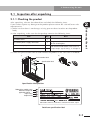
2.1 Inspection after unpacking
2.1.1 Checking the product
After unpacking, take out the robot driver and check the following items.
If you find or suspect any damage to the product please contact our sales office or sales
representative.
2
(1) Make sure that there is no damage, missing parts or dents/scratches on the product
body.
Before using the unit
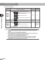
(2) After unpacking, make sure that the package contains the following items.
Item
Qty
1) Robot driver
1
2) Control power supply connector
1
3) Connector plug
1
4) Connector cover non-shielded shell kit
1
Note
Supplied with a wire inserter tool and
B1-B2 shorting bar.
For detailed information, refer to 3.2.4,
"Input/output signal wiring", in Chapter 3.
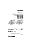
(3) Check the specification label to find whether the product is the same item as ordered.
1)
2)
Serial number label
X
RD
Specification label
Specification label position
Robot driver model name
Maximum output for
applicable motor
Input rating
Output rating
NE
882 Soude, Naka-ku, Hamamatsu, Shizuoka 435-0054, Japan
Details on specification label
2-1
2. Before using the unit
X05 –
05
X
0001
Production number
Production month
2
Robot driver model No.
Before using the unit
X05
X10
X20
P05
P10
P20
P25
RDX-05
RDX-10
RDX-20
RDP-05
RDP-10
RDP-20
RDP-25
1 to 9 January to September
O
October
X
November
Y
December
Production year: Last 2 digits of year
Details on serial number label
2.1.2 User's manual
This user's manual describes how to use the YAMAHA single-axis robot driver RD series.
Before using the RD series, read this manual thoroughly in order to handle and operate it
correctly. Store this manual carefully even after reading it.
2-2
2. Before using the unit
2.2 Product inquiries and warranty
2.2.1 Notes when making an inquir y
If you need to inquire about possible product damage, failures or points that are unclear,
then please contact us with the following information.
2
(1) Robot driver model
Before using the unit
(2) Production number
(3) Date of purchase
(4) Details of your inquiry
• Damaged section and condition, etc.
• Dubious point and description, etc.
2.2.2 Warranty
For information on the product warranty, please contact your local agent where you
purchased your product.
2-3
2. Before using the unit
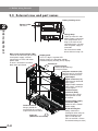
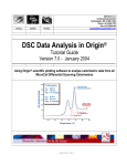
2.3 External view and part names
Battery housing cover
Battery holder
Not used.
2
Before using the unit
Charge lamp
Lights up when the main
power supply is turned on.
This lamp remains lit as
long as the main circuit
capacitor retains a charge
after the power supply is
turned off.
Do not touch the robot
driver while the lamp is lit.
Main circuit terminal block (TM1)
Terminals for connecting to the main
circuit power supply, external
regenerative resistor, and motor
power cable.
A cover is fitted to this terminal
block when purchased.
Display panel
This is a 5-digit 7-segment LED
display used as the operation monitor,
parameter display and trip (alarm) display.
X
RD
Ground terminal
Always ground the
unit through this terminal
to prevent electrical shock.
Intake air
(Natural air convection)
2-4
Exhaust air
Digital operator
Use these operator keys
to set parameters.
Computer connector (PC)
Connects to a PC (personal
computer) for data transfer.
Input/output
signal connector (I/O)
Connector for command
input signals,
programmable controller
input signals, and origin
sensor signals.
Position sensor
connector (ENC)
Connects to the linear
motor position sensor
or resolver.
Control power supply
connector (TM2)
Connects to the control
power supply.
B1-B2 shorting bar
Always connect this
shorting bar when using an
internal braking resistor
(RD*-20 and RDP-25).
(RD*-05 and RD*-10 have
no internal braking resistor.)
2. Before using the unit
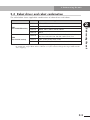
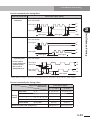
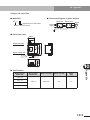
2.4 Robot driver and robot combination
The table below shows applicable combinations of robot drivers and robots.
Robot driver name
RDX
(For FLIP-X series)
Applicable robots
RDP-05
MR12, MR16
RDP-10
MR16H, MR25, MF7
RDP-20
MR20, MF15, MF20, MF30, MF50
RDP-25
MF75
RDX-05
T4H, T5H, T6, T7, T9, F8, F8L, F8LH, F10, F14, B10, B14,
R5, R10, C4H, C5H, C6, C8, C8L, C8LH, C10, C14
RDX-10
T9H, F14H, B14H, R20, C14H
RDX-20
F17, F17L, F20, F20N, N15, N18, C17, C17L, C20
2
Note: Parameters are adjusted at the factory prior to shipping so that the robot driver operates
to control the target robot. Please contact us if you want to change the target robot model
after shipping.
2-5
Before using the unit
RDP
(For PHASER series)
Model No.
MEMO
2-6
Chapter 3
Installation and wiring
This chapter explains how to install the robot driver, as well as how to connect wiring to the main
circuit and input/output signals. Typical connection examples are shown.
Contents
3.1
Installation
3-1
3.1.1
Precautions during installation
3.2
Wiring
3-4
3.2.1
3.2.2
3.2.3
3.2.4
3.2.5
Terminal block and connectors
Main circuit wiring
Wiring to the control terminal block (TM2)
Input/output signal wiring
Wiring for position sensor signals
3-4
3-5
3-13
3-14
3-27
3-2
3. Installation and wiring
3.1 Installation
c
Screw size
Tightening torque (N•m)
M3
0.6 to 0.9
M4
1.5 to 2.1
M5
2.8 to 3.9
M6
4.1 to 5.3
M8
13.9 to 20.0
Note
Mounting screws for robot
driver and peripheral devices
8. Provide the specified clearance between the robot driver and the inner
surface of the control panel or any other unit.
Failure to do so may cause malfunction.
9. Do not allow foreign matter such as cut wire fragments, welding debris, iron
waste or similar items to penetrate inside.
Doing so may cause fire.
10. Avoid applying strong shock to the unit to prevent malfunction.
11. Do not install the unit if any part is damaged or missing.
Doing so may cause fire or injury.
3-1
3
Installation and wiring
CAUTION
1. Do not step or stand on the unit. Do not place heavy objects on the unit.
Doing so may cause injury.
2. Do not block the air intake and exhaust vents. Do not allow foreign matter
or debris to penetrate inside.
Doing so may cause fire.
3. Always use the correct method to install the unit.
The unit may malfunction if not properly installed.
4. Install the robot driver on a perpendicular wall not subject to vibration.
The unit may fall and injure someone if not properly installed.
5. Install the unit on a surface made of incombustible materials such as metal.
Failure to do so may cause fire.
6. Install the unit at a place strong enough to support the weight of the unit.
The unit may fall and injure someone if not properly installed.
7. Tighten the screws to the specified torque. Make sure that all screws are
securely fastened before operation.
The unit may fall and injure someone if not properly installed.
3. Installation and wiring
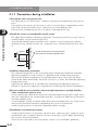
3.1.1 Precautions during installation
3
(1) Precautions when carr ying the unit
The robot driver uses plastic parts. Handle it carefully to avoid damage to the plastic
parts.
Take special care not to carry the unit in such a way that force is applied only to the
front cover or terminal block cover. Otherwise you might drop the unit.
Do not install and operate the unit if any part is damaged or missing.
Installation and wiring
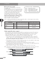
(2) Install the unit on an incombustible (metal) surface.
The robot driver becomes hot during operation. To prevent fire always install it on an
incombustible, straight vertical metal wall.
Also provide enough space around the unit. If there is any heat generating device
(braking resistor, electric reactor, etc.), keep the unit a sufficient distance away from
it.
Provide enough space so that upper/lower
wiring ducts will not block cooling air flow.
Air flow
Robot driver
Wall
(3) Ambient temperature precautions
The ambient temperature in the installation place should not exceed the allowable
operating temperature range (0 to 40˚C) specified in the standard specifications.
Measure the ambient temperature at a position about 50mm away from the lower
center of the robot driver body, and make sure that it is within the allowable operating
temperature range.
Operating the robot driver at a temperature exceeding the allowable range may
shorten its service life (especially, capacitor life) or damage the internal components.
(4) Do not install the unit in locations subject to high temperatures and high humidity
where condensation tends to occur.
Always operate the robot driver within the allowable operating humidity range (20 to
90% RH) specified in the standard specifications. In particular, operate it in locations
free from condensation.
If water droplets formed inside the robot driver due to condensation, this might cause
short-circuits between electronic components that result in malfunction.
Avoid installing the unit in locations exposed to direct sunlight.
(5) Installation environment precautions
Avoid installing the unit in locations subject to dust, corrosive gases, explosive gases,
combustible gases, grinding lubricant mist or salt damage. Dust or debris penetrating
the unit may cause malfunction.
If the unit must be used in very dusty place, house it in a sealed dust-proof box.
3-2
3. Installation and wiring
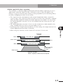
(6) Installation method and direction precautions
Install the robot driver on a vertical surface capable of supporting the weight. Secure
the robot driver firmly by screws or bolts.
If the robot driver is not installed vertically on the wall surface, the cooling capacity
may degrade causing a trip or alarm and/or damaging the internal components.
For mounting hole locations, refer to 8.2, "Robot driver dimensions and mounting
holes".
3
100mm or more
Fan
Fan
Installation and wiring
(7) Precautions when housing robot drivers in a box
When housing multiple robot drivers in a box and using ventilation fans, attach the
fans as shown below in order to ensure a uniform temperature around each robot
driver.
Wiring space of
75mm or more
Robot
driver
100mm or more
40mm or
more
10mm or
more
10mm or
more
10mm or
more
40mm or
more
Install the robot drivers 40mm or more away from the inner side walls of the box and
100mm or more away from the inner top/bottom walls of the box. Allow a clearance
of 10mm or more between adjacent robot drivers.
3-3
3. Installation and wiring
3.2 Wiring
w
3
Installation and wiring
c
DANGER
1. WIRING WORK SHOULD BE CARRIED OUT BY QUALIFIED ELECTRICIANS.
IMPROPER WIRING MAY CAUSE ELECTRICAL SHOCK OR FIRE.
2. ALWAYS FIRST INSTALL THE UNIT BEFORE CARRYING OUT WIRING.
FAILURE TO DO SO MAY CAUSE ELECTRICAL SHOCK OR INJURY.
3. MAKE SURE THE POWER IS OFF BEFORE CARRYING OUT WIRING.
FAILURE TO DO SO MAY CAUSE ELECTRICAL SHOCK OR FIRE.
CAUTION
1. Make sure that wiring connections are correct.
Wrong connections may cause abnormal robot motion resulting in injury.
2. Cables connecting to the robot driver should be securely fastened near the
robot driver so that no tensile stress is applied to the cables.
Stress on the cables may lead to malfunction.
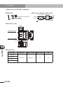
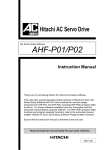
3.2.1 Terminal block and connectors
The terminal block and connectors on the robot driver are shown below.
RDX
FUNC
CHARGE
Main circuit terminal block
(TM1)
SET
Computer connector (PC)
Input/output signal connector (I/O)
Position sensor connector (ENC)
Ground terminal
Control power supply connector (TM2)
3-4
3. Installation and wiring
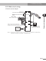
3.2.2 Main circuit wiring
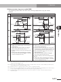
(1) Terminal connection diagram
Shorting bar
(DC reactor connecting terminal)
Regenerative braking resistor
(option)
TM1
TM1
(+)1
U
(+)
V
Robot driver
W
3
RB
(-)
Installation and wiring
Power supply
3-phase 200 to 230 V AC
L1
Note 1)
L2
L3
ELB
MG
ENC
TM2
L1C
L2C
When using external regenerative
braking resistor, disconnect B1-B2 shorting bar.
B1
I/O
Master
controller
PC
B2
PC for parameter setting
and operation monitoring
Origin sensor
Note 1: Regenerative braking resistor is built in RD*-20 and RDP-25 robot drivers.
(Not built into RD*-05 and RD*-10 robot drivers.)
3-5
3. Installation and wiring
(2) Terminal assignment
Terminal
block
connector
Terminal assignment
Shorting
bar
Main
circuit
terminal
block
(TM1)
3
Installation and wiring
(+)1
(+)
RB
(–)
L1
L2
L3
U
V
W
Ground
terminal
Control
power
connector
(TM2)
c
3-6
B1
B2
L1C
L2C
Terminal
width (mm)
M4
8.1
M4
–
DC reactor connection terminal
(Short these terminals when not used.)
External braking resistor connection terminal
DC power input terminal
Main power input terminal
Motor power cable connection terminal
Ground connection terminal
Shorting
bar
Terminal
screw
size
Shorting terminals for internal braking resistor
(Open when external resistor is used.)
Control power input terminal
Note: Diagram is shown as viewed from bottom of
robot driver.
Applicable
wire size:
1.25 to 2.0
mm 2
CAUTION
1. Unplug the control power supply connector from the robot driver before
wiring.
Failure to do so may damage the robot driver.
2. When inserting the wires into the terminal, be careful not to bring the core
wire braid into contact with other conductive parts.
Failure to do so may damage the robot driver.
3. If for some reason the inserted portion of the wire is frayed, cut off that
frayed portion and restrip the wire. Then reconnect the wire securely.
Using frayed wire may damage the robot driver.
3. Installation and wiring
(3) Wiring precautions
Before starting wiring, make sure that the charge lamp is completely off. Use caution
because the capacitor might still be charged with high voltage creating a hazardous
condition. About 10 minutes or more after power-off use a voltmeter or similar
instrument to check that no voltage remains across the (+) and (–) terminals on the
main circuit terminal block, and then start wiring.
1) Main power input terminals (L1, L2, L3)
• Some earth leakage breakers may malfunction due to effects from higher
harmonics, so use one having large current sensitivity at high frequencies.
• Connect an electromagnetic contactor that shuts off the power supply to the robot
driver to prevent a failure or accident from spreading when the robot driver's
protective function is activated.
• Do not attempt to start or stop the robot driver by turning on or off each
electromagnetic contactor provided on the primary side and secondary side of the
robot driver.
• Do not use the robot driver in an open-phase condition.
• Any of the following conditions may damage the converter module so use caution.
The power supply voltage imbalance is 3% or more.
The power supply capacity is 10 times larger than the robot driver capacity or
500kVA or more.
A sudden fluctuation occurs in the power supply.
(Example) Multiple robot drivers are connected to each other by a short bus
line.
In any case, connecting a DC reactor (DCL) is recommended.
• When turning power on or off allow at least a 5-minute time interval between
power on and off in order to avoid damage to the robot driver.
2) Motor cable connection terminals (U, V, W)
• To minimize voltage drops, use thicker wires than normally used.
3) DC reactor (DCL) connection terminals ( (+)1, (+) )
• These terminals are used to connect a DC reactor DCL for power factor
improvement.
A shorting bar is connected across terminals (+)1 and (+) at the factory prior to
shipping. When connecting a DC reactor to these terminals, disconnect the
shorting bar. When not using a DC reactor, leave the shorting bar connected.
3-7
3
Installation and wiring
• Use an earth leakage breaker (ELB) to protect circuit (wiring) between the power
supply and main power input terminals (L1, L2, or L3).
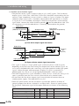
3. Installation and wiring
4) External braking resistor connection terminals ( (+), RB) )
• A regenerative braking circuit and braking resistor are built into the robot drivers
(RD*-20 and RDP-25). To enhance braking capacity, you can connect an optional
external braking resistor to these terminals. In this case, disconnect the shorting
bar from the internal braking resistor terminals (B1, B2). The wiring length should
be 5 meters or less. Wire by twisting the two wires together.
• Install a resistor whose resistance is higher than the R BRmin specified in the
following table.
Installing a resistor whose resistance is lower than specified will damage the
regenerative braking circuit.
3
Installation and wiring
Robot driver model
Built-in braking resistor R BR
Minimum resistance R BRmin
RD*-05
None
100Ω
RD*-10
None
100Ω
RD*-20
30W 75Ω (10W, 0.5%)
50Ω
RDP-25
50W 50Ω (15W, 0.5%)
40Ω
Note: The power (wattage) of built-in braking resistor R BR is the nominal value. The
values in parentheses indicate the available average power (W) and allowable
duty ratio (%).
For details on external braking resistors, refer to 10.1, "Options".
5) DC power input terminals ( (+), (–) )
• Connect a DC power supply to these terminals when supplying DC power from an
external converter. Use a DC power supply that provides 270 to 310V DC and has
sufficient capacity.
• When supplying DC power, do not connect anything to the main power input
terminals (L1, L2, L3).
• When supplying DC power, set the "DC bus power supply" (FA-07) parameter to
"Pn". If this is not set, an open-phase or momentary power failure will be
mistakenly detected.
6) Control power input terminals (L1C, L2C)
• In addition to the main circuit power supply, this robot driver requires a control
power supply. Be sure to connect a single-phase AC power supply to these control
power input terminals (L1C, L2C). Also use a circuit (wiring) protection breaker or
earth leakage breaker along with the control power supply. Some earth leakage
breakers may malfunction due to effects from higher harmonics, so use one having
large current sensitivity at high frequencies. When turning power on or off, allow
at least a 5-minute time interval between power on and off. Turning power on or
off at shorter time intervals may damage the robot driver.
7) Shorting terminals for internal braking resistor (B1, B2)
• When using the internal braking resistor, short the terminals B1 and B2 together.
When using an external braking resistor, disconnect the shorting bar from these
terminals. (The RD*-20 and RDP-25 have an internal braking resistor.)
3-8
3. Installation and wiring
8) Ground terminals (
)
• To prevent electrical shock, be sure to ground the robot driver and the robot
body.
• Connect the ground terminals to a proper grounding point (Class D: 100 ohms or
less).
• The ground wire should be thicker than those generally used and as short as
possible.
3
Note 2: Separate the robot driver signal input cable and position sensor cable at
least 30cm from the main circuit power cable and control power cable. If
those cables must intersect each other, then route them so that they
intersect at right angles as shown below. The robot driver may result in
malfunction if the cables are not separated from each other.
Main circuit power cable
(L1, L2, L3, U, V, W, (+), (+)1, RB)
Control power supply cable
(L1C, L2C)
Cables should intersect at right angles.
Signal input and position sensor cables
30cm or more
3-9
Installation and wiring
Note 1: To connect wiring to the terminal block, use crimp terminals that match
the terminal width. If the crimp terminal width is too wide, then a bad
connection or misconnection may result.
3. Installation and wiring
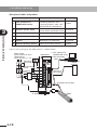
(4) Peripheral cables and products
Name
3
Function
Availability
Installation and wiring
1
TOP (software for
YAMAHA RD series)
Allows setting parameters,
monitoring operation and
displaying graphics from a PC
connected to the robot driver.
Option
2
Position sensor cable
Connects to the robot position
sensor, brake and origin sensor.
Standard
3
Power cable
Supplies power to the robot.
Standard
4
PC connection cable
Connects to a PC.
Option
5
Connector set for I/O
signals
Mating connector and cover for
robot driver I/O connector
Standard
6
External braking resistor
Boosts the braking capacity.
Option
Typical wiring diagram for robot driver is shown below.
Power supply
3-phase 200 V AC class
(Single-phase
200 V AC class: L1, L2)
Robot driver
1. TOP (software for
YAMAHA RD series)
4. PC connection
cable
Earth leakage
breaker (ELB)
PC (IBM PC compatible)
Master
controller
FUNC
SET
CHARGE
6. External braking
resistor
(+)1
I/O
Electromagnetic
contactor
5. Connector set
for I/O signals
2. Position sensor cable
ENC
3. Power cable
3-10
Robot
3. Installation and wiring
(5) Recommended wire size and wiring accessories
• Select optimal breakers by taking their breaking capacity into account.
• Use an earth leakage breaker (ELB) to ensure safety.
• Use an appropriate copper wire with a heat resistant temperature of 75˚C or more.
• Tighten the terminal screws to the specified torque. Insufficient tightening may
result in a short circuit or fire.
• Refer to the following table when selecting wiring size and wiring accessories for
robot drivers.
Robot
driver
model
Main circuit
power cable
L1, L2, L3
(+)1, (+), RB, (–)
Control power
cable
L1C, L2C
Earth leakage
breaker (ELB) *
Electromagnetic
contactor (MC) *
RD*-05
1.25mm 2 or more
0.5mm 2 or more
EX30 (5A)
H10C / HK10
RD*-10
1.25mm 2 or more
0.5mm 2 or more
EX30 (5A)
H10C / HK10
RD*-20
1.25mm 2 or more
0.5mm 2 or more
EX30 (5A)
H10C / HK10
RDP-25
1.25mm 2 or more
0.5mm 2 or more
EX30 (10A)
H10C / HK10
* : ELB and MC models listed in the above table are manufactured by Hitachi Industrial
Equipment Systems Co., Ltd.
(Hitachi standard ELB products manufactured from December 1987 are compatible with
inverters.)
3-11
3
Installation and wiring
• Select the sensitivity current of the earth leakage breaker (ELB) by taking account of
the total wiring length needed to connect between the robot driver and power
supply and also between the robot driver and robot. When the total wiring length is
shorter than 30 meters, use a 15mA sensitivity current (per one robot driver).
Use an earth leakage breaker compatible with inverters. Conventional breakers may
malfunction by high harmonics generated from an inverter. Contact the breaker
manufacturer for details.
3. Installation and wiring
(6) Attaching the cover to the main circuit terminal block (TM1)
1. Insert the bottom hook of the main circuit terminal block cover into the slot in the
robot driver front panel as shown below.
2. Attach the main circuit terminal block cover into place by gently pressing on it
from the front.
3
3. Tighten the screw to fasten the main circuit terminal block cover to the robot
driver.
Installation and wiring
RD
X
2
3
Main circuit terminal block cover
1
3-12
3. Installation and wiring
3.2.3 Wiring to the control terminal block (TM2)
c
(1) Cable termination
Strip the cable sheath as shown in Fig. 1. The cable can then be used as is. Applicable
wire size is as follows:
Solid wire ....... Wire size 1.25 to 2.0mm 2
Stranded wire ... Wire size 1.25 to 2.0mm 2
8 to 9mm
Fig. 1 Control power cable termination
(2) Connection method
Insert the core wire of the cable into the terminal hole of the control power connector
(TM2) shown in Fig. 2 by using either of the following methods of Fig. 3 and Fig. 4.
Make sure the wire does not come loose if pulled.
1) Insert the wire by using the supplied lever as shown in Fig. 3.
2) Insert the wire by using a small flat-blade screwdriver as shown in Fig. 4.
L2C
L1
B1B2
Fig. 2 Control power connector
Fig. 3
Fig. 4
3-13
3
Installation and wiring
CAUTION
1. Unplug the control power supply connector (TM2) from the robot driver
before wiring.
Failure to do so may damage the robot driver.
2. Insert one cable into one terminal hole of the control power connector (TM2).
Failure to follow this instruction may cause the robot driver to malfunction.
3. When inserting the wires into the terminal, be careful not to bring the core
wire braid into contact with other conductive parts.
Failure to do so may damage the robot driver.
4. If for some reason the inserted portion of the wire is frayed, cut off that
frayed portion and restrip the wire. Then reconnect the wire securely.
Using frayed wire might damage the robot driver.
3. Installation and wiring
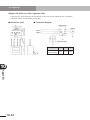
3.2.4 Input/output signal wiring
(1) Input/output signal connector
3
Installation and wiring
Pin No.1 of the input/output signal
connector I/O is located at the upper
left when viewed from the front of the
robot driver as shown on the right.
The table below shows the signal
assignment on the input/output signal
connector I/O (robot driver side).
FUNC
SET
CHARE
1
26
Input/output signal
connector I/O
25
50
Robot driver front view
Pin
No.
Pin
symbol
Signal name
Pin
No.
Pin
symbol
1
P24
Interface power
26
SON
2
PLC
Intelligent input common
27
RS
3
–
28
FOT
–
Signal name
Servo ON
Alarm reset
Forward overtravel
4
TL
Torque limit
29
ROT
Reverse overtravel
5
B24
Brake power input (24V)
30
CM1
Interface power common
6
B0
Brake power input (0V)
31
B0
7
–
32
ORG
–
Brake power input (0V)
Return-to-origin (homing)
8
ORL
Origin sensor
33
PEN
9
CER
Position error clear
34
ALME
10
CM1
Interface power common
35
SRD
11
ALM
Alarm (collector)
36
–
–
12
INP
Positioning complete
(collector)
37
–
–
13
BK
Brake release relay output
38
–
14
–
–
39
Pulse train input enable
Alarm (emitter)
Servo ready (collector)
–
INPE
Positioning complete
(emitter)
15
PLSP
Position command pulse (P)
40
SIGP
Position command sign (P)
16
PLSN
Position command pulse (N)
41
SIGN
Position command sign (N)
17
–
–
42
SRDE
Servo ready (emitter)
18
–
–
43
–
–
19
–
–
44
–
–
Analog input /output
common
45
–
–
20
L
21
OAP
Phase A signal output (P)
46
OBP
Phase B signal output (P)
22
OAN
Phase A signal output (N)
47
OBN
Phase B signal output (N)
23
OZP
Phase Z signal output (P)
48
OZ
24
OZN
Phase Z signal output (N)
49
L
25
AO1
Analog monitor 1
50
AO2
3-14
Phase Z detection
Phase Z detection common
Analog monitor 2
3. Installation and wiring
On the mating input/output signal connector (cable side), pin No.1 is located at the
upper left when viewed from the soldered side (inner side) as shown below.
The following connector is supplied with the controller as the input/output signal
connector (cable side).
Product name
Type No.
Manufacturer
Connector plug
10150-3000PE (soldered)
Sumitomo 3M
Connector cover
non-shield shell kit
10350-52A0-008
Sumitomo 3M
PLC
4
TL
6
BO
8
ORL
10
CM1
12
INP
14
−
16
PLSN
18
−
20
L
22
OAN
24
OZN
3
2
4
6
1
3
5
27
29
31
26
28
30
5
7
9
22
24
23
25
47
49
48
50
11
13
15
Soldered side of
input/output signal connector
17
19
21
23
25
P24
27
RS
29
ROT
31
BO
33
PEN
35
SRD
37
−
39
INPE
41
SIGN
43
−
45
−
47
OBN
49
L
−
B24
−
CER
ALM
BK
PLSP
−
−
OAP
OZP
AO1
26
SON
28
FOT
30
CM1
32
ORG
34
ALME
36
−
38
−
40
SIGP
42
SRDE
44
−
46
OBP
48
OZ
50
AO2
Installation and wiring
1
2
3
Note 1: For robots using an origin sensor or robots equipped with a mechanical
brake, the input/output signal connector is shipped with pin No. 1, 8, 10,
13 and 31 soldered.
Note 2: Brake release relay output (BK) is not available from the RDP.
3-15
3. Installation and wiring
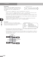
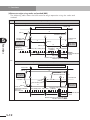
(2) Input/output signal connection diagram
Standard input/output signal connections are shown below.
Robot driver
Pulse train position
command (pulse)
Pulse train position
command (sign)
3
15 PLSP 1507
OAP 21
16 PLSN
OAN 22
40 SIGP 1507
OBP 46
41 SIGN
OBN 47
OZP 23
Installation and wiring
OZN 24
Origin sensor
8 ORL 4.7k7
24V
10 CM1
L 49
DC24V
Interface power
Contact input common
Servo ON
Alarm reset
Torque limit
Forward overtravel
Reverse ovetravel
Return-to-origin
Pulse train input
enable
Position error
counter clear
Interface power common
OZ 48
1 P24
AO1 25
26 SON4.7k7
AO2 50
27 RS 4.7k7
20
Logic ground
L
SRD 35
28 FOT 4.7k7
SRDE 42
ALM 11
29 ROT4.7k7
ALME 34
INP 12
32 ORG4.7k7
33 PEN 4.7k7
9 CER4.7k7
Position sensor
Phase B signal output
Position sensor
Phase Z signal output
Phase Z detection
Phase Z detection common
Logic ground
2 PLC
4 TL 4.7k7
Position sensor
Phase A signal output
INPE 39
Brake release
relay
BK 13
Monitor output 1
Monitor output 2
Analog output common
Servo ready
Alarm
Positioning complete
Brake output and coil
(Note 1)
30 CM1
Br
31.6
BRK
B0
Brake power
DC24V
5
B24
The above diagram shows a sink type output module using a power supply for internal
input.
3-16
3. Installation and wiring
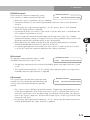
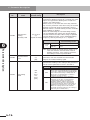
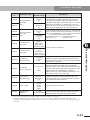
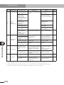
(3) Input/output signal functions
Input/output signal functions are summarized in the following table.
Type
Terminal
symbol
P24
Supplies 24V DC for contact inputs.
Connecting this signal to the PLC
terminal allows using the internal
power supply. Use this terminal only for
contact input. Do not use for controlling
external equipment connected to the
robot driver, such as brakes.
CM1
Interface power
common
PLC
Intelligent input
common
Connect this signal to the power
supply common contact input. Connect
an external supply or internal power
supply (P24).
Servo ON
Setting this signal to ON turns the
servo on (supplies power to motor to
control it). This signal is also used for
estimating magnetic pole position when
FA-90 is set to oFF2.
RS
Alarm reset
After an alarm has tripped, inputting
this signal cancels the alarm. But
before inputting this reset signal, first
set the SON terminal to OFF and
eliminate the cause of the trouble.
TL
Torque limit
When this signal is ON, the torque limit
is enabled.
FOT
Forward overtravel
When this signal is OFF, the robot will
not run in forward direction.
(Forward direction limit signal)
ROT
Reverse overtravel
When this signal is OFF, the robot will
not run in reverse direction.
(Reverse direction limit signal)
ORL
Origin sensor
Input an origin limit switch signal
showing the origin area.
ORG
Return-to-origin
Inputting this signal starts return-toorigin operation.
PEN
Pulse train input
enable
When this signal is turned on, the
pulse train position command input is
enabled.
CER
Position error counter
clear
Inputting this signal clears the position
deviation (position error) counter.
(Position command value is viewed as
current position.)
Analog common
This is the ground for the analog
signal.
L
Electrical
specifications
3
DC +24V±10%
80mA max.
Contact input
Close: ON
Open: OFF
5mA (at 24V)
per input
0 to ±10V
Input
impedance:
approx. 10kΩ
3-17
Installation and wiring
Analog
common
Interface power
Description
This is a ground signal for the power
supply connected to P24. If using the
internal power supply then input a
contact signal between this signal and
the contact-point signal.
SON
Input
signal
Terminal name
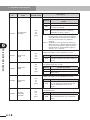
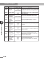
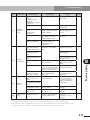
3. Installation and wiring
Type
Terminal
symbol
SRD
SRDE
3
Output
signal
Installation and wiring
Relay
output
INP
INPE
Positioning complete
This signal is output when the deviation
between the command position and
current position is within the preset
positioning range.
BK
(B24)
Brake release relay
output
When the servo is ON, this terminal
outputs a signal to allow releasing the
brake. (FLIP-X series only)
(Note 1)
Outputs speed detection values, torque
commands, etc. as analog signal
voltages for monitoring.
Signals to output are selected by
setting parameters.
These signals are only for monitoring.
Do not use for control.
Monitor output 2
L
Monitor output
common
This is the ground for the monitor
signal.
Position command
pulse
(pulse signal)
Select one of the following signal forms
as the pulse-train position command
input.
(1) Command pulse + direction signal
(2) Forward direction pulse train +
reverse direction pulse train
(3) Phase difference 2-phase pulse
PLSN
SIGP
Position command
pulse
(sign signal)
Position sensor
Phase A signal
Outputs monitor signal obtained by
dividing "phase A" signal of position
sensor.
Position sensor
Phase B signal
Outputs monitor signal obtained by
dividing "phase B" signal of position
sensor.
OZN
Position sensor
Phase Z signal
Outputs monitor signal for position
sensor "phase Z" signal.
OZ
Phase Z detection
L
Phase Z detection
common
B24
Brake power input
Input 24V DC brake power to this
terminal
Brake power common
Common terminal input for brake
power
OAP
OAN
OBP
Brake
power
input
Monitor output 1
AO2
SIGN
Position
sensor
monitor
This signal is output when the servo
is ready to turn on (with main power
supply turned on and no alarms
tripped.)
Alarm
PLSP
Position
command
Servo ready
Description
An alarm signal is output when an
alarm has tripped. (This signal is ON in
normal state and OFF when an alarm
has tripped.)
ALM
ALME
AO1
Monitor
output
Terminal name
OBN
OZP
(Note 1)
B0
(Note 1)
Outputs monitor signal for position
sensor "phase Z" signal.
Note 1:B24, BO and BK are available only with RDX, and not with RDP.
3-18
Electrical
specifications
Open collector
and emitter
signal output
+30V DC or
less, 50mA
max. per
output
24V DC
375mA max.
0 to ±3.0V
Load
impedance:
3kΩ or more
Line driver
input
Line driver
signal output
Open collector
output +30V
DC or less,
50mA max.
24V DC input
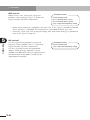
3. Installation and wiring
(4) Brake and origin sensor connector
Among the input/output signals, the brake and origin sensor signals are connected to a
connector that is branched from the input/output signal connector. By connecting this
branched connector to the position sensor cable, the brake can be released and
return-to-origin performed by sensor method.
Use this connector only when using a robot with a mechanical brake or robot's returnto-origin method is sensor method.
Robot driver
3
Host device
SET
CHARGE
(+)1
I/O
Robot driver
BK
Robot
13
1
31
2
1
3
8
4
10
5
ENC
B0
Robot
P24
ORL
CM1
Pin No. on
Terminal
connector side symbol
Signal name
Br
Pin No. on robot
driver side
1
BK
Brake release relay output
13
2
B0
Brake power input (0V)
31
3
P24
Power supply for input signal
1
4
ORL
Origin sensor
8
5
CM1
Power supply (common) for input signal
10
3-19
Installation and wiring
FUNC
3. Installation and wiring
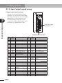
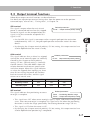
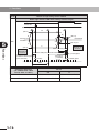
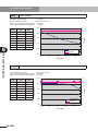
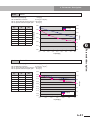
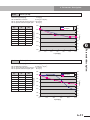
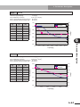
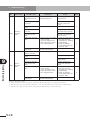
(5) Details of input/output signal wiring
1) Contact input signal
• Contact signals should be input through switches and relays. Figures (a) and (b)
below show wiring diagrams using an external power supply or internal interface
power supply.
Robot driver
P24
External power supply
(DC24V)
PLC
3
Installation and wiring
Switch
Robot driver
Short-circuit P24
DC24V
DC24V
PLC
Switch
Input 4.7k7
CM1
Input 4.7k7
CM1
(a) When using an external power supply
(b) When using the internal power supply
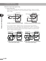
• Use an external power supply for devices requiring power for controlling a
contact output, such as a programmable controller output module. (Do not use
the internal interface power supply of the robot driver.) Figures (c) and (d) below
show examples for connecting the transistor output module (sink type or source
type) of a programmable controller.
Programmable
P24
controller External power
Robot driver
DC24V
Programmable
P24
controller External power
supply (DC24V)
S
Output
Output
control
C
CM1
(c) When using a sink type output module
and an external power supply
3-20
DC24V
supply (DC24V)
PLC
Input 4.7k7
Robot driver
Output
control
C
PLC
Output
Input 4.7k7
S
CM1
(d) When using a source type output module
and an external power supply
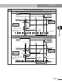
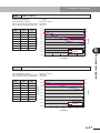
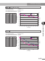
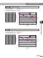
3. Installation and wiring
• When using an external power supply, do not connect to the internal interface
power of the robot driver. If connected, current may flow as shown in figure (e)
below when the external power supply is shut off, causing the input to turn on.
Robot driver
Programmable
controller External power supply P24
DC24V
(DC24V)
PLC
S
Shorted when
Example of sink
power is shut off.
type output module
Input 4.7k7
Output
3
C
CM1
(e) Current flow when external power supply is shut off
• If using switch contacts or relay contacts as the contact input signal, then use
contacts such as crossbar twin contacts that make good contact even at weak
currents or voltages.
• Do not short the internal interface power P24 to CM1. The robot driver may fail.
• The electrical specifications for input signals are shown in the following table.
(Power supply voltage 24V DC)
Item
Unit
Minimum
Maximum
Input impedance
kΩ
4.5
5.7
Input current at OFF
mA
0
0.3
Input current at ON
mA
3.0
5.2
Condition
Power supply voltage
24V DC
3-21
Installation and wiring
Output
control
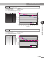
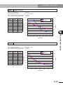
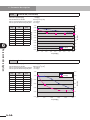
3. Installation and wiring
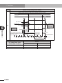
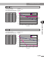
2) Open collector output signal
• Connect a relay coil or the input module of a programmable controller as shown
in Figures (a) and (b) below. When using a relay, connect a diode as a surge
absorber in parallel with the coil. Connect that diode as shown in Figure (a) so
that the current flow direction of the diode is opposite the direction that voltage is
applied to the coil.
Robot driver
3
Programmable
controller
Robot driver
C
Surge-absorbing diode
Installation and wiring
Output
(Collector)
Relay coil
Input
Output
External power
supply
(DC24V)
External power
supply
(DC24V)
(Emitter)
(Emitter)
(a) Relay coil connection
(b) Programmable controller connection
• Prepare an external power supply for output signals. Do not use the internal
interface power supply (P24-CM1) of the robot driver. The robot driver may fail.
• Electrical specifications for contact output signals are shown in the following
table.
3-22
Item
Unit
Minimum
Maximum
Output power supply
voltage
V
–
30
Output current at ON
mA
–
50
Leakage current at
output OFF
mA
–
0.1
Output saturation
voltage at ON
V
0.5
1.5
Condition
Output current 50mA
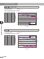
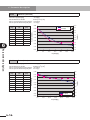
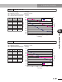
3. Installation and wiring
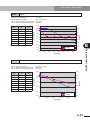
3) Monitor output signal
• Connect a meter (voltmeter) or recorder for monitoring speed detection values
and torque command values as shown in Figure (a) below. Use this signal only for
monitoring and not for commands to other control devices. (Output signal
accuracy is about ±10%.) Each monitor output signal cable should be a shielded,
twisted pair cable with the analog common (L--- connector pin No. 20, 49).
) on the robot driver side. (The I/O
Connect the cable shield to ground (
connector case of the robot driver is internally connected to the ground.)
Robot driver
Installation and wiring
Shielded cable
AO1,
AO2
D/A converter
Voltmeter
L
Connector
case
Logic ground
(a) Monitor output signal connection
• The impedance of the load to connect to this monitor signal should be 3kΩ or
more.
Do not connect the monitor output signal (AO1, AO2) to the common (L) or
another power supply. The robot driver may fail.
• Electrical specifications for monitor output signals are shown in the following
table.
Item
Unit
Specifications
V
0 to ±3.0
Load impedance
kΩ
3.0 or more
Output voltage accuracy
%
±10 or more
Output signal delay time
ms
Approx. 1
Output voltage
3
3-23
3. Installation and wiring
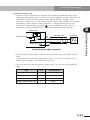
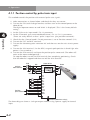
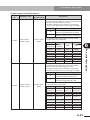
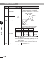
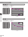
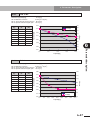
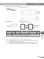
4) Position command signal
• Connect the pulse train signal for position command. As shown in the figure
below, the line receiver receives a pulse train signal output from the line driver
(AM26LS31 or equivalent) of the master controller.
Each position command signal cable should be a shielded, twisted pair cable.
) on the robot driver side. (The I/O
Connect the cable shield to ground (
connector case of the robot driver is internally connected to the ground.)
3
Line driver
(AM26LS31)
Shielded cable
Installation and wiring
PLSP,
SIGP
PLSN,
SIGN
Robot driver
1507
Connector
case
• Electrical specifications and timing chart for position pulse signals are shown in
the following table.
Electrical specifications for position command pulses
Item
Input current of logic 1
• FWD/REV pulse
input
Maximum input
pulse rate
(Frequency)
• Command pulse
+ sign input
• Phase difference
90° pulse input
3-24
Unit
Specifications
Condition
mA
8 to 15
pulses/s
2M
Line driver
signal
pulses/s
500k
Line driver
signal
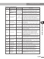
3. Installation and wiring
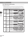
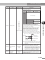
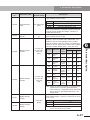
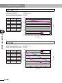
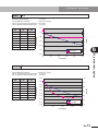
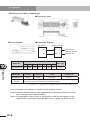
Position command pulse timing chart
Pulse train signal form
(1) Pulse train
command
Pulse train input timing
When FA-11 = P-S (Movement direction is reversed if FA-11 = -P-S.)
See note below.
"1"
PLS signal
t1
t0
"0"
t2
t S4
t S2
"1"
T
SIG signal
t S1
t S3
t3
(2) FWD/REV pulse
"0"
Logic
REV signal
When FA-11 = F-r (Movement direction is reversed if FA-11 = r-F.)
See note below.
"1"
PLS signal
t1
t0
"0"
t2
T
"1"
SIG signal
"0"
t S0
FWD signal
(3) Phase difference
2-phase pulse
REV signal
When FA-11 = A-b (Movement direction is reversed if FA-11 = b-A.)
See note below.
* In the case of
phase difference
2-phase pulse,
the count is
multiplied by 4.
PLS signal
(Phase A)
"1"
t1
"0"
t2
t0
T
SIG signal
(Phase B)
"1"
t5
"0"
t6
FWD signal
REV signal
Note: When at logic 1, the pulse train input current direction is PLSP→PLSN, SIGP→SIGN.
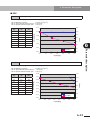
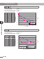
Position command pulse timing values
Pulse train signal form
(See above)
Timing
values
Line driver signal
(1), (2) above
(3) above
Rise time
: t 1, t 3
0.1μs or less
0.1μs or less
Fall time
: t 2, t 4
0.1μs or less
0.1μs or less
Switching time
: t S0, t S1, t S2, t S3, t S4
3μs or more
–
Phase difference : t 5, t 6
Pulse width
: (t 0/T)×100
Maximum pulse rate (frequency)
–
50±10%
50±10%
2M (pulses/s)
500k (pulses/s)
3-25
3
Installation and wiring
FWD signal
t4
3. Installation and wiring
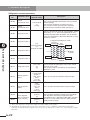
3
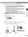
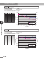
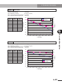
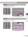
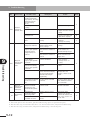
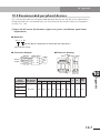
5) Position sensor monitor signal
• The position sensor signal is output as phase A, B, and Z signals. The line driver
output signals (OAP-OAN, OBP-OBN, OZP-OZN) should be connected to the line
receiver (input impedance: 220 to 330 Ω) as shown in Figure (a) below. The open
collector output signal (OZ-L) should be connected to the input device as shown
in Figure (b). Use a shielded, twisted pair cable for each position sensor monitor
) on the robot driver side. (The
signal cable. Connect the cable shield to ground (
I/O connector case of the robot driver is internally connected to the ground.)
Robot driver
Installation and wiring
OAP,
Line driver
(AM26LS31 or equivalent) OBP,
OZP,
OAN,
OBN,
OZN,
Line receiver
(AM26LS32 or equivalent)
Shielded cable
R
R=220
to 3307
L
L
(a) Line driver output signal connection
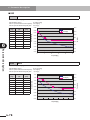
Robot driver
High-speed
2.2k7 photocoupler
Shielded cable
Open collector
SIGN
OZ
External power
supply
(DC24V)
L
Connector
case
Logic ground
(b) Open collector output signal connection
• This signal is output as a high speed signal (1MHz for phase A and B signals)
depending on the division ratio setting for the position sensor monitor signal. So
use a noise-shielded cable and a receiving circuit designed to handle high-speed
signals. When the open collector output of phase Z signal is received by a
photocoupler, be sure to use a high-speed photocoupler (1MHz or more).
• The cable length for this signal should be 3 meters or less. Install this wiring as far
apart as possible from the main circuit cable and the relay control cable.
• Do not short the line driver output signals to each other or connect them to
another power supply. The robot driver may fail.
• Electrical specifications for the line driver signal output conform to those of
general-purpose line drivers (AM26LS31 or equivalent). Electrical specifications
for the phase Z detection signal of the open collector are shown in the following
table.
Item
Unit
Minimum
Maximum
V
4
30
Output current at ON
mA
0
50
Leakage current at output OFF
mA
0
0.1
Output saturation voltage at ON
V
0
0.4
Output power supply voltage
3-26
Condition
Output current 50mA
3. Installation and wiring
3.2.5 Wiring for position sensor signals
(1) Position sensor signal connector
Connector compatible with lead-free solder
Type No.
Manufacturer
54599-1015
Molex
3
• Description of terminal code
Pin No.
Terminal
symbol
Pin No.
Terminal
symbol
1
EP
Position sensor
power supply 5V
2
EG
4
EG
Position sensor
power supply
Common 0V
3
EP
5
SIN+
Sine output (+)
6
SIN–
Sine output (–)
7
COS+
Cosine output (+)
8
COS–
Cosine output (–)
9
Z+
Phase Z (+) output
10
Z–
Phase Z (–) output
Pin No.
Terminal
symbol
Signal name
2
R2
4
R2
Signal name
Installation and wiring
RDP ENC connector terminal symbol
Signal name
RDX ENC connector terminal symbol
Pin No.
Terminal
symbol
1
R1
3
R1
5
S2
S2-S4 coil output
terminal
6
S4
S2-S4 coil output
terminal
7
S1
S1-S3 coil output
terminal
8
S3
S1-S3 coil output
terminal
9
–
10
–
Signal name
Position sensor
excitation input
terminal
–
2
4
EG(R2)
EG(R2)
1
3
EP(R1)
EP(R1)
6
8
SIN-(S4) COS-(S3)
5
7
SIN+(S2) COS+(S1)
Position sensor
excitation input
terminal
–
10
Z–
9
Z+
Numbers in parentheses indicate position sensors used with the RDX.
3-27
MEMO
3-28
Chapter 4
Operation
This chapter explains typical product operation and shows simple trial runs.
Contents
4.1
Control and operation
4.1.1
Position control by pulse train input
4.2
Test Run
4.2.1
4.2.2
Jog from the digital operator
Making a test run using "TOP"
software for RD series
4.3
Emergency stop
4-1
4-2
4-3
4-3
4-4
4-6
4. Operation
4.1 Control and operation
c
MANDATORY
INSTALL AN EXTERNAL EMERGENCY STOP CIRCUIT SO THAT YOU CAN
IMMEDIATELY STOP OPERATION AND SHUT OFF POWER WHENEVER NEEDED.
4-1
4
Operation
CAUTION
1. To prevent unstable or erratic operation never make drastic adjustments to
the unit. Doing so may cause injury.
2. Install a safety circuit that actuates an electromagnetic contactor to cut off
the main circuit power supply in case of an alarm.
3. If an alarm has occurred, eliminate the cause of the alarm and ensure
safety. Then reset the alarm and restart the operation.
Failure to do so may cause injury.
4. If a momentary power outage occurs and power is restored, the unit might
suddenly restart so do not approach the machine at that time. (Design the
machine so that personal safety is ensured even if it suddenly restarts.)
Failure to do so may cause injury.
5. Make sure that the AC power specifications match the product power
specifications.
Using the wrong power specifications may cause injury.
6. While power is being supplied, do not touch any parts inside the robot driver
or its terminals.
Also, do not check the signals or attach/detach the cables.
Doing so may cause electrical shock or injury.
7. While power is being supplied, do not touch any terminals on the robot
driver even if the robot is stopped.
Doing so may cause electrical shock or fire.
8. This product does not incorporate any power failure detection function.
When necessary, install an external power failure detection circuit and
configure an appropriate circuit that stops the operation safely when a
power failure is detected. (Refer to 4.3, "Emergency stop", in this chapter.)
4. Operation
4.1.1 Position control by pulse train input
This method controls the position with external pulse train signals.
1) Make connections as shown below and check that they are correct.
2) Turn on the ELB (earth leakage breaker) and then turn on the control power to the
robot driver.
The digital operator comes on and "d-00" is displayed. (This is the factory default
setting.)
4
3) Set the "Pulse train input mode" (FA-11) parameter.
4) Set the "Electronic gear numerator/denominator" (FA-12, FA-13) parameters.
(These are set by default so that 1 pulse is equal to a 1µm position command.)
Operation
5) Check that the "Control mode" (FA-00) parameter is set to "Position control" (P-S).
6) Turn on the FOT and ROT terminals.
7) Turn on the electromagnetic contactor MC and then turn on the main circuit power
supply.
8) Turn on the SON terminal. (On the RDP, magnetic pole position is found right after
power is first turned on.)
9) Turn on the PEN terminal and input the position pulse command. (The robot will
move to the commanded position.)
To stop the robot, turn off the PEN terminal after completing positioning. Check
that the robot has stopped and then turn off the SON terminal.
ELB
MC
L1
L2
L3
3-phase
200 to 230 V AC
200 to 230V
Robot driver
Digital operator U
L1C
L2C
Robot
V
W
ENC
Down transformer
Position
pulse command
P24
PLC
SON
RS
FOT
ROT
PEN
CER
CM1
PLSP
PLSN
SIGP
SIGN
Ground (100 ohms or less)
The above diagram shows a sink type output module using a power supply for internal
input.
4-2
4. Operation
4.2 Test Run
This section explains how to make a test run.
4.2.1 Jog from the digital operator
Jog can be performed from the digital operator just by wiring the robot driver to the robot
and power supply.
This test run method allows checking the wiring between the robot driver, robot and
power supply.
(1) Jog operation
Blinking
FUNC
Blinking
Blinking
Operation
Perform the following steps with the SON terminal turned off.
1) Operate the FUNC and
keys to
show the "Jogging speed" (Fb-03)
parameter setting.
× 3 times 2) Set the operation speed by using
the
,
and
keys. (The
example on the left shows the
operating procedure for changing
only the run direction.)
To reverse the run direction, set the
or
speed with a negative sign. Enter
the sign in the second digit column
from the left on the LED display.
SET : Saves the setting.
FUNC : Does not save
the setting. Blinking
Run
4
3) To perform jog operation, select the
most significant digit with the
key.
4) Press the
key while in the
above state.
Jog operation now starts to move
the robot, so use caution.
5) Press any of the following keys to
stop the operation.
key: Continues displaying the
setting.
SET key: Saves the speed setting.
FUNC key: Returns to the menu
display without saving the
speed setting.
Note: When a PHASER series robot is used, magnetic pole position estimation must
be performed before this operation. For information on magnetic pole
position estimation,refer to section 5.17, "Magnetic pole position estimation
action".
4-3
4. Operation
4.2.2 Making a test run using "TOP" software for RD series
Jog can be run from a PC. During this jog operation, wiring checks can be made for the
robot driver, robot and power supply because no outside connections to the I/O
connector are needed. For details, refer to the TOP (software for RD series) user's
manual.
There are two types of jog operation: (1) normal jog performed at a specified speed and
(2) pulse feed jog that moves a distance equal to a specified number of pulses.
Each of these is explained below.
4
Operation
Note 1: Do not input any signals through the I/O connector including the SON
terminal during this operation. Doing so runs the operation according to the
input terminal.
Note 2: In this jog operation, the robot moves at an acceleration/deceleration time of
0 seconds and the current settings for control gain and speed limit
parameters.
Note 3: This jog operation cannot be used simultaneously with the TOP monitor
display.
Note 4: When a PHASER series robot is used, magnetic pole position estimation must
be performed before this operation. For information on magnetic pole
position estimation,refer to section 5.17, "Magnetic pole position estimation
action".
(1) Operation in normal jog
In normal jog, the robot moves at a constant speed specified by the speed command
until a stop command is input.
After starting the TOP (software for RD series), run the jog operation as explained
below.
1) After connecting the TOP to the robot driver, click the [Test Run and Adjustment] button on
the opening screen.
(Click the [Jogging] tab.)
2) Enter the speed command for jog operation.
3) Check safety and then click the button that indicates the direction to move the robot.
(The robot will start moving in the specified direction.)
4) Click the [Stop] button to stop operation.
Note: The robot moves during this operation, so check safety before starting
operation.
4-4
4. Operation
(2) Pulse feed jog operation
In this jog operation, the robot moves in position control mode up to the position
specified by the position command.
After starting the TOP software for RD series, run jog operation as explained below.
Refer to the TOP software user's manual for details.
1) Click the [Test Run and Adjustment] button on the opening screen.
(Click the [Jogging] tab.)
2) Enter the number of feed pulses.
3) Check safety and then click the [Forward] or [Reverse] button.
(The robot will start moving in the specified direction and stop at the position specified by
the command.)
4
Operation
4) After positioning is complete, the display returns to the initial screen.
The servo is still ON at this point so click the [Stop] button.
Note: The robot moves during this operation, so check safety before starting
operation.
To stop positioning, click [Stop] button.
4-5
4. Operation
4.3 Emergency stop
To safely stop the robot in case of an emergency, configure an emergency stop circuit
while referring to the explanations below.
For details on input terminal functions and parameters, refer to 5.2, "Input terminal
functions" and 6.3.2, "Setup parameter description".
(1) Ser vo OFF
4
When the SON signal is turned off, the servo is OFF and the braking is applied by the
dynamic brake.
Operation
• The DB Operation selection (FA-16) must be set to "SoF". The braking is not applied
by the dynamic brake unless this selection is set to "SoF".
• When the Servo OFF wait time (FA-24) is set, the servo is OFF and the braking is
applied by the dynamic brake after the SON signal has been turned off and the
servo OFF wait time has elapsed.
(2) How to shorten the braking distance
Shorten the breaking distance by producing the deceleration torque through the servo
control.
Example)
Deceleration torque is produced by clamping the speed command at zero.
• The servo OFF wait time is set, and the SON signal and FOT/ROT signal
are turned off at the same time in case of an emergency.
• The speed command is clamped at zero by the FOT/ROT signal OFF
while the servo OFF is delayed. At this time, the deceleration torque is
produced to shorten the braking distance.
FOT
ROT
SON
Main power
Servo
FA-24
V
Speed command
0
V
Current speed
0
Note 1: If the heavy braking is applied as described in the example shown above
when the payload of the robot is large or offset, the deceleration torque
becomes too large, causing the robot to break. In this case, it is
recommended that the FOT/ROT signal is not turned off and the position
command is changed so that the speed command changes gradually.
Note 2: When the servo is OFF if a trip occurs, the power to the motor is shut down
immediately even when the Servo OFF wait time has been set.
4-6
Chapter 5
Functions
This chapter explains the input/output signal functions of this product and its major control
functions.
Contents
5.1
Terminal function list
5-1
5.2
Input terminal functions
5-3
5.3
Output terminal functions
5-7
5.4
Return-to-origin function
5-10
5.5
Analog output function
5-21
5.6
Pulse train input function
5-22
5.7
Smoothing function
5-25
5.8
Position sensor monitor function
5-26
5.9
Adjusting the control gain
5-27
5.9.1
5.9.2
5.9.3
Basic rules of gain adjustment
Setting the mechanical rigidity and response
Adjusting the position control loop
5.10 Offline auto-tuning function
5.10.1 Offline auto-tuning method
5.10.2 Offline auto-tuning using the TOP software
5-27
5-28
5-29
5-30
5-30
5-33
5.11 Gain change function
5-35
5.11.1 Changing the control gain
5-35
5.12 Clearing the alarm log and setting
the default values
5-38
5.13 Motor rotating direction
5-40
5.13.1 FLIP-X series phase sequence
5.13.2 PHASER series phase sequence
5-40
5-40
5.14 Speed limit function
5-41
5.15 Fast positioning function
5-42
5.16 Notch filter function
5-44
5.17 Magnetic pole position estimation action 5-45
5.18 Magnetic pole position estimation
and parameters
5-46
5. Functions
5.1 Terminal function list
Type
Terminal
symbol
P24
Interface power
CM1
Interface power
common
This is a ground signal for the power supply
connected to P24. If using the internal power supply
then input a contact signal between this signal and
the contact-point signal.
PLC
Intelligent input
common
Connect this signal to the power supply common
contact input. Connect an external supply or internal
power supply (P24).
5
Servo ON
Setting this signal to ON turns the servo on (supplies
power to motor to control it). This signal is also used
for estimating magnetic pole position when FA-90 is
set to oFF2.
RS
Alarm reset
After an alarm has tripped, inputting this signal
cancels the alarm. But before inputting this reset
signal, first set the SON terminal to OFF and
eliminate the cause of the trouble.
Functions
Analog
common
Contact
point
output
signal
Function
Supplies 24V DC for contact inputs. Connecting this
signal to the PLC terminal allows using the internal
power supply. Use this terminal only for contact
input. Do not use for controlling external equipment
connected to the robot driver, such as brakes.
TL
Torque limit
When this signal is ON, the torque limit is enabled.
FOT
Forward
overtravel
When this signal is OFF, the robot will not run in
forward direction.
(Forward direction limit signal)
ROT
Reverse
overtravel
When this signal is OFF, the robot will not run in
reverse direction.
(Reverse direction limit signal)
ORL
Origin sensor
Input an origin limit switch signal showing the origin
area.
ORG
Return-to-origin
Inputting this signal starts return-to-origin operation.
PEN
Pulse train input
enable
When this signal is turned on, the pulse train position
command input is enabled.
CER
Position error
counter clear
Inputting this signal clears the position deviation
(position error) counter. (Position command value is
viewed as current position.)
L
Analog common
This is the ground for the analog signal.
SRD
SRDE
Servo ready
This signal is output when the servo is ready to turn
on (with main power supply turned on and no alarms
tripped.)
ALM
ALME
Alarm
An alarm signal is output when an alarm has tripped.
(This signal is ON in normal state and OFF if an
alarm has tripped.)
INP
INPE
Positioning
complete
This signal is output when the deviation between the
command position and current position is within the
preset positioning range.
SON
Contact
point
input
signal
Terminal name
5-1
5. Functions
Type
Relay
output
Monitor
output
Terminal
symbol
Terminal name
BK
(B24)
Brake release
relay output
AO1
Monitor output 1
AO2
Monitor output 2
L
Monitor output
common
PLSP
5
Position
command
PLSN
SIGP
Functions
SIGN
OAP
OAN
OBP
OBN
Position
sensor
monitor
Brake
power
input
5-2
OZP
OZN
Position
command pulse
(pulse signal)
Function
When the servo is ON, this terminal outputs a signal
to allow releasing the brake. (FLIP-X series only)
Outputs speed detection values, torque commands,
etc. as analog signal voltages for monitoring.
Signals to output are selected by setting parameters.
These signals are only for monitoring. Do not use for
control.
This is the ground for the monitor signal.
Position
command pulse
(sign signal)
Select one of the following signal forms as the pulsetrain position command input.
(1) Command pulse + direction signal
(2) Forward direction pulse train + reverse direction
pulse train
(3) Phase difference 2-phase pulse
Position sensor
"phase A" signal
Outputs monitor signal obtained by dividing "phase
A" signal of position sensor.
Position sensor
"phase B" signal
Outputs monitor signal obtained by dividing "phase
B" signal of position sensor.
Position sensor
"phase Z" signal
Outputs monitor signal for position sensor "phase Z"
signal.
OZ
"Phase Z"
detection
L
"Phase Z"
detection
common
B24
Brake power
input
Input 24V DC brake power to this terminal.
B0
Brake power
common
Common terminal input for brake power.
Outputs monitor signal for position sensor "phase Z"
signal.
5. Functions
5.2 Input terminal functions
Functions of the robot driver input terminals are described below.
For details on input/output terminal timing chart from the power-on to the position
command input, refer to 10.1, “Timing chart”, in Chapter 10.
SON terminal
Setting this signal to ON turns the servo on
(supplies power to the servo).
The timing chart is shown below.
This signal is also used by the magnetic pole
position estimation operation of the RDP. See
5.17, "Magnetic pole position estimation
action" for more details.
Related parameters
FA-16 : DB Operation selection
FC-01 : Input terminal polarity setting
• When the "DB operation selection" (FA-16) parameter is set to "SoF" (during servo
OFF), the dynamic brake engages by turning the servo off.
• Period from input of a servo-ON signal until the operation is ready to start is 20ms.
• By changing the "Input terminal polarity" (FC-01) setting, the servo can also be
turned on when this input terminal is opened.
• When the SON signal is switched from OFF to ON, the position command is set to
the current position and the deviation (position error) counter is cleared.
Power
SRD
10 [ms] or more
1000 [ms] or more
FOT/ROT
SON
RDX operation
Power-off
Servo-off
Normal servo-on
RDX
Power
SRD
10 [ms] or more
1000 [ms] or more
FOT/ROT
SON
RDP operation
Power-off
Servo-off
Magnetic pole
position estimation
Normal servo-on
RDP
5-3
5
Functions
• Receives a servo-ON signal and enters the servo-ON state (when SRD is ON) only
when the main circuit power supply is connected and no alarm has tripped. Unless
all these conditions are met, no power is supplied even when this signal is ON.
However, magnetic pole position estimation can be performed even if SRD is not
ON.
5. Functions
RS terminal
When an alarm has tripped, setting the SON
signal to OFF and this RS signal to ON clears
the tripped alarm state, and operation can
resume.
Related parameters
FC-01 : Input terminal polarity setting
• If no alarm has tripped, this signal is ignored even if set to ON.
• When an alarm has tripped and then this signal is switched from OFF to ON, the
alarm trip state is canceled if the ON state lasts more than 20ms.
• Even if this signal remains at the ON state, reset operation is performed only once.
• By changing the "Input terminal polarity" (FC-01) setting, alarms can also be reset
when this input terminal is opened.
5
• The RS terminal might not always be able to cancel a tripped state, due to the
problem that triggered the alarm. See "9.3 Troubleshooting".
Functions
TL terminal
Setting this terminal to ON enables torque
limit. Use the parameters Fb-07 through Fb-10
to determine the torque limit values.
Related parameters
FA-00
:
FA-17
:
Fb-07 to 10 :
FC-01
:
Control mode
Torque limit mode
Torque limit value 1 to 4
Input terminal polarity setting
• By changing the "Input terminal polarity" (FC-01) setting, torque limit can also be
enabled when this input terminal is opened.
• The parameters Fb-07 through Fb-10 limit the torque in each quadrant as shown in
the figure below. (However, use the absolute value as the torque limit value when
entering the parameters.)
Torque
Second
First
quadrant
quadrant
Fb-08
Fb-07
Speed
Fb-09
5-4
Third
quadrant
Fourth
quadrant
Fb-10
5. Functions
FOT/ROT terminals
These terminals connect to operating range
limit switches in order to prevent overtravel.
Related parameters
FC-01 : Input terminal polarity setting
• When this signal is turned on, drive is allowed.
• To prevent overtravel, the internal speed command limit value in that direction is
set to 0.
• By changing the "Input terminal polarity" (FC-01) setting, drive is also allowed
when this input terminal is opened.
• An overtravel error (E25) occurs if the servo is ON for more than 1 second after the
FOT and ROT were both set to OFF.
• The FOT and ROT terminal function does not change even if the FA-14 (Motor
revolution direction) setting is changed. The FOT always prohibits drive in the CCW
direction and the ROT prohibits drive in the CW direction.
• A magnetic pole position estimation error (E95) occurs if either of the FOT or ROT
is set to OFF while the magnetic pole position is being estimated.
PEN terminal
The position command pulse input is valid
(enabled) only when this signal is ON.
Related parameters
FC-01 : Input terminal polarity setting
• The position command value can be refreshed by pulse train input while this signal
is ON.
• The "Input terminal polarity" (FC-01) setting allows position pulse train input to be
enabled when this input terminal is opened.
CER terminal
This signal clears the deviation (position error)
counter to "0" by setting the position command
value as the current position during position
control.
Related parameters
FC-01 : Input terminal polarity setting
• This signal is only valid during position control. The position command value is set
to the current position value at the instant this signal is switched from OFF to ON.
Since this signal turns on at the pulse edge, the counter clearing does not continue
even if this signal is kept ON. To clear the counter again, set this signal to OFF and
then back ON again.
• By changing the "Input terminal polarity" (FC-01) setting, the deviation counter can
also be cleared when this input terminal is opened.
5-5
5
Functions
• When operating the robot with the RDP, the magnetic pole position estimation
should be performed with the FOT and ROT set to ON.
5. Functions
ORG terminal
When servo is ON, tuning this signal ON
performs return-to-origin. See 5.4, "Return-toorigin function" for more information.
Related parameters
FA-23: Homing mode
Fb-12: Homing speed 1 (fast)
Fb-13: Homing speed 2 (slow)
FC-01: Input terminal polarity setting
• When return-to-origin is complete, INP turns ON. If this signal is turned OFF before
return-to-origin is complete, the movement is interrupted and INP stays OFF.
• Since this signal turns ON at the pulse edge, only one return-to-origin is performed
even if this signal is kept ON.
5
Functions
ORL terminal
Use this signal when performing return-toorigin by sensor method. See 5.4, "Return-toorigin function" for more information.
Use this signal only when the connected
robot's return-to-origin method is sensor
method. No additional wiring is required since
the connection to the robot is made via the
input/output connector.
5-6
Related parameters
FA-23: Homing mode
FC-01: Input terminal polarity setting
5. Functions
5.3 Output terminal functions
Robot driver output terminal functions are described next.
For details on input/output terminal timing chart from the power-on to the position
command input, refer to 10.1, “Timing chart”, in Chapter 10.
SRD terminal
This signal is output when the main circuit
power is connected and no alarm has tripped.
Servo-ON signals can be accepted when this
signal is ON, but cannot be accepted if this
signal is OFF.
Related parameters
FC-02 : Output terminal polarity setting
5
• By changing the "Output terminal polarity" (FC-02) setting, this output terminal can
also be opened when the servo is ready.
ALM terminal
This signal indicates that an alarm has tripped,
and can be set to "normally open" or "normally
closed" by the "Output terminal polarity
setting" (FC-02). (Default setting is "normally
closed" contact.) The table below shows the
relation between each contact specification
and alarm output. When this signal indicates
an alarm has tripped, then inputting an alarm
reset (RS) or turning the power off and then
back on cancels that alarm, and this signal
returns to its normal state.
Related parameters
FC-02 : Output terminal polarity setting
Contact specifications
Power OFF
Normal state
Alarm state
Normally closed
OFF
ON
OFF
Normally open
OFF
OFF
ON
INP terminal
This signal indicates that positioning or returnto-origin is complete.
Related parameters
Fb-23 : Positioning detection range
FC-02 : Output terminal polarity setting
• This signal turns OFF when return-to-origin signal is input, and return-to-origin then
starts. After return-to-origin is complete, this signal turns ON when the positioning
deviation is within the range specified by "Positioning detection range" (Fb-23).
• This signal is OFF when the servo is OFF.
• By changing the "Output terminal polarity" (FC-02) setting, this output terminal can
also be opened when positioning is completed.
5-7
Functions
• On the RDP, this signal is not output unless magnetic pole position estimation
ended correctly. See 5.17, "Magnetic pole position estimation action" for more
details.
5. Functions
BRK terminal (relay contact)
This signal is for controlling an externally
installed brake.
Use this signal only when the connected robot
has a mechanical brake. No additional wiring
is required since the connection to the robot
is made via the input/output connector.
Two methods of brake signal output are
available: output while the motor is stopped
and output while the motor is operating. As
shown in the table below, each setting can be
made to exclude the other setting. Their
output methods are described below.
5
Related parameters
FA-24
FA-26
FA-27
FC-02
:
:
:
:
Servo OFF wait time
Brake operation start speed
Brake operation start time
Output terminal polarity setting
Note: In the case of the RDP, this signal cannot be used as a relay output since no relay
is mounted on the PC board in the RDP.
Functions
Parameter
(1) Brake signal during stop
(2) Brake signal during run
Servo OFF wait time
FA-24
Wait time setting
0
Brake operation start
speed
FA-26
–
Start speed
Brake operation start
time
FA-27
0
Start time
This function will not work correctly unless the exclusive setting is made as shown above.
(1) Brake signal while robot is stopped
In this function, after the brake signal (BRK) has turned on, the servo OFF signal can
be delayed in order to counteract delays in the brake operation. So use this signal
when the robot stops such as when stopped after positioning. Using this signal
frequently while the robot is moving will cause abnormal brake wear.
• This signal turns on simultaneously with servo ON operation when a servo-ON
signal is input. This signal immediately turns off when the servo ON signal turns
off. The servo then turns off after a time preset by the "Servo OFF wait time" (FA-24)
parameter has elapsed. (See figure below.)
• The "Servo OFF wait time" (FA-24) can be set from 0 to 1.00 seconds in 10ms steps,
and operation may have a maximum delay of 1ms.
• If an alarm trips then the servo turns off simultaneously with this signal.
• By changing the "Output terminal polarity" (FC-02) setting, this output terminal can
also be opened when the brake is released.
• When using this function, set the "Brake operation start time" (FA-27) to 0.
Note: Operation is controlled by pulse train input even during the "Servo OFF wait time".
To stop the operation, turn off the PEN input or stop the pulse train input.
SON
Servo ON state
Servo OFF wait time
FA-24
5-8
Servo status
Power being supplied
BRK
Brake OFF state
5. Functions
(2) Brake signal while robot is operating
This function is used when applying the brake while the robot is operating so use in
applications where the robot can slow sufficiently such as when the robot is freerunning. Using this function when moving a heavy payload may cause braking delays,
resulting in dropping hazards so use caution.
• This signal turns on simultaneously with servo ON operation when a servo-ON
signal is input. Also, when the servo turns off or an alarm trips, the brake is applied
when the robot speed falls below the "Brake operation start speed" (FA-26) or after
the "Brake operation start time" (FA-27) has elapsed after the servo turns off. (See
figure below.)
• The "Brake operation start time" (FA-27) can be set from 0 to 1.000 second in 4ms
steps, and operation may have a maximum delay of 1ms.
• By changing the "Output terminal polarity" (FC-02) setting, this output terminal can
also be opened when the brake is released.
SON=OFF
or alarm
SON
Servo status
Servo ON state
Power being supplied
Brake operation start time
FA-27
BRK
Robot speed
Brake OFF status
5
Functions
• When using this function, set the "Servo OFF wait time" (FA-24) to 0.
*
Brake operation
start speed
FA-26
*Operation condition
FA-26 > | Speed | or FA-27 time has elapsed.
5-9
5. Functions
5.4 Return-to-origin function
(1) Return-to-origin using stroke end method (RDX)
The following table shows the RDX return-to-origin operation using the stroke end
method.
FA-23
Return-to-origin using stroke end method
Stroke end
When "Homing back distance" (Fb-35) = 1
2
(Fb-12)
3
1
Reverse run
Position
5
Forward run
7
6
2048
Machine reference (d-18)
{L- {[(Fb-35)-1]×4096+2048}}/4096
t-F
(4) 5
(Machine reference=100%)
Functions
4096
Phase Z
2048
First Z
Homing back distance
counter
L
(Fb-12)
Stroke end
4
When "Homing back distance" (Fb-35) = 2
5
Reverse run
Position
6
(Fb-13)
7
Forward run
{L- {[(Fb-35)-1]×4096+2048}}/4096
(Machine reference=100%) 1
Machine reference (d-18)
2
(Fb-12)
2048
4096
3
t-r
Homing back distance
counter
4096
Phase Z
First Z
2048
[(Fb-35)-1]×4096
L
1. Start return-to-origin.
Operation sequence
2. Robot moves towards stroke end at return-to-origin speed (Fb-12).
3. Reverses movement direction while adjusting speed during acceleration/deceleration time
(Fb-04, Fb-05) when the robot has reached the stroke end, which is determined by detecting (in
first part of this step) a motor current exceeding the rated current and then the specified
"Stroke-end current" (Fb-36). (Note 1)
4. Moves in direction opposite the stroke end at return-to-origin speed (Fb-12). Starts counting
the Homing back distance from the stroke end. (If the "Homing back distance" (Fb-35) is set
to 1, then step 4 is skipped and goes to step 5.)
5. When the Homing back distance count exceeds "[(Fb-35) – 1] × 4096" pulses, the robot starts
slowing down during deceleration time (Fb-05) and moves at slow return-to-origin speed
(Fb-13). (Note 1)
6. Continues moving at slow return-to-origin speed (Fb-13).
7. Stops at first "phase Z" position after the Homing back distance count has exceeded
"[(Fb-35) – 1] × 4096+2048" pulses.
(Machine reference is displayed on d-18, which is calculated as follows:
{ L (distance from stroke end to stop point)–{[(Fb-35) – 1]× 4096+2048}} / 4096)
Note 1: The acceleration/deceleration time parameters specify the time needed to accelerate or decelerate
between 0 and maximum speed.
5-10
5. Functions
(2) Return-to-origin using sensor method (RDX)
The following table shows the RDX return-to-origin operation using the sensor
method.
ORL terminal at start of return-to-origin using sensor method
FA-23
OFF
ON
Sensor
4096 pulses (machine reference=100%) (ORL)
Sensor
(ORL)
4096 pulses (machine reference=100%)
Machine reference (d-18)
Machine reference (d-18)
2
S-F
3
(Fb-12)
4
(Fb-13)
1
(Fb-12)×0.5
5
6
5
Reverse run
Forward run
Position
(Note 3) A
4
Reverse run
A
(Note 3)
3
(Fb-12)×0.5
First phase Z
(Fb-13)
Forward run
7
1 Position
2 First phase Z
Phase Z
Phase Z
Machine reference (d-18)
Reverse run 5
A
S-r
(Fb-13)
4
3
(Fb-12)×0.5
(Note 3)
Forward run
Position
1
2
First phase Z
Operation sequence
Phase Z
Sensor
(ORL)
4096 pulses (machine reference=100%)
Machine reference (d-18)
2
(Fb-12)×0.5
A
3
1
(Note 3)
Reverse run
7
6
5
Forward run
Position
(Fb-12)×0.5
4
First phase Z
Phase Z
1. Start return-to-origin.
1. Start return-to-origin.
2. Robot moves towards origin at return-to-origin
speed (Fb-12).
2. Robot moves away from origin at 50% of
return-to-origin speed (Fb-12).
3. Slows down during deceleration time (Fb-05)
when sensor (ORL terminal) turns on. (Note 5)
3. Reverses movement direction when sensor (ORL
terminal) turns off. (Deceleration/acceleration time
is determined by parameters (Fb-05, Fb-04). (Note 5)
4. Continues moving at slow return-to-origin speed
(Fb-13).
5. Stops at first "phase Z" position after reaching
the slow return-to-origin speed (Fb-13). (Machine
reference displayed on d-18.) (Note 3)
4. Moves back towards origin at 50% of return-toorigin speed (Fb-12). (Note 4)
5. Slows down during deceleration time (Fb-05)
when sensor (ORL terminal) turns on. (Note 5)
6. Continues moving at slow return-to-origin speed
(Fb-13).
7. Stops at first "phase Z" position after reaching
the slow return-to-origin speed (Fb-13). (Machine
reference displayed on d-18.) (Note 3)
Note 1: If the origin sensor (ORL terminal) does not turn off even when the robot has moved a distance of 50,000 pulses
after starting return-to-origin with the origin sensor (ORL terminal) turned on (operation in steps 1 and 2), then an
origin sensor alarm (E80) occurs.
Note 2: If the origin sensor (ORL terminal) does not turn on and the robot comes into contact with the mechanical end
(stroke end), then an overload alarm (E05) occurs.
Note 3: Machine reference is displayed after return-to-origin is completed normally.
Note 4: If the origin sensor (ORL terminal) turns on during acceleration, then the robot immediately slows down and sets
to step 5. (Speed might not always reach 50% of return-to-origin speed (Fb-12) ).
Note 5: Acceleration/deceleration time parameters set the time needed to accelerate or decelerate between 0 and
maximum speed.
5-11
Functions
Sensor
4096 pulses (machine reference=100%)(ORL)
5
5. Functions
(3) Return-to-origin using stroke end method (RDP)
The following table shows the RDP return-to-origin operation using the stroke end
method.
FA-23
Return-to-origin using stroke end method
When phase ZM is between return-to-origin start position and stroke end
When "Homing back distance" (Fb-35) = 2
2
(Fb-12)
3
Reference phase Z
1
Reverse run
Position
7
9
R side
4096
8
When FA-14
is set to CC
(Fb-12)
Phase Z
(Dotted line indicates
phase ZY.)
256(=100H) 768 (=300H) pulses
(R/D converter)
5
Stroke end
Phase ZM
Forward run
4
(Fb-13)
Functions
6
5
[(Fb-35)-1]×4096
1024 pulses 768 (=300H) pulses
(1.024mm)
4096
4096
256(=100H)
d
L side
When FA-14
is set to CC
Homing back distance
counter
Machine reference (d-18)=(d+256)/4096
Machine reference=100%
t-F
When return-to-origin start position is between phase ZM is and stroke end
Stroke end
When "Homing back distance" (Fb-35) = 1
Phase ZM
8
(Fb-12) 7
2
R side
When FA-14
is set to CC
1
3
Reverse run
Position
14
(Fb-13)
6
(Fb-12)
Phase Z
(Dotted line indicates
phase ZY.)
(R/D converter)
Reference phase Z
1024 or more pulses
5
13
12
4096
10 (11)
4
Forward run
L side
When FA-14
is set to CC
1024 pulses 768 (=300H) pulses
768 (=300H) pulses 256(=100H) (1.024mm)
4096
4096
256(=100H)
d
Machine reference (d-18)=(d+256)/4096
Machine reference=100%
5-12
9
Homing back distance
counter
5. Functions
FA-23
Return-to-origin using stroke end method
When phase ZM is between return-to-origin start position and stroke end
Stroke end
When "Homing back distance" (Fb-35) = 2
Phase ZM
Reference phase Z
5
R side
When FA-14
is set to CC
6
(Fb-12)
[(Fb-35)-1]×4096
7
4096
(Fb-13)
4
Reverse run
Position
L side
When FA-14
is set to CC
6
9
Forward run
8
1
3
2
d
Homing back
distance counter
1024 pulses
(1.024mm)
4096
768(=300H)
4096
Machine reference (d-18)=(d+768)/4096
Machine reference=100%
t-r
When return-to-origin start position is between phase ZM and stroke end
Stroke end
When "Homing back distance" (Fb-35) = 1
Phase ZM
1024 or more pulses
4
(Fb-12)
Reference phase Z
R side
When FA-14
is set to CC
10 (11)
Reverse run
Position
12
4096
(Fb-13)
3
1
6
2
7
8
256(=100H)
1024 pulses
768 (=300H) pulses 768(=300H) (1.024mm)
d
L side
When FA-14
is set to CC
Forward run
14
13
9
Homing back
distance counter
5
4096
768(=300H)
(Fb-12)
Phase Z
(Dotted line indicates
phase ZY.)
(R/D converter)
4096
Machine reference (d-18)=(d+768)/4096
Machine reference=100%
5-13
5
Functions
256(=100H)
768 (=300H) pulses
(Fb-12)
Phase Z
(Dotted line indicates
768(=300H) phase ZY.)
(R/D converter)
5. Functions
Return-to-origin using stroke end method
FA-23
Functions
Operation sequence
5
When phase ZM is between return-to-origin start
position and stroke end
1. Start return-to-origin.
2. Robot moves towards stroke end at return-to-origin
speed (Fb-12).
3. Continues moving towards the stroke end at returnto-origin speed (Fb-12).
Starts counting "Homing back distance" after
detecting the sensor signal (phase ZM).
Among phase Z at each 4096 count, the phase Z
detected at a point closest to the stroke end is
regarded as reference phase Z.
4. Reverses movement direction while adjusting speed
during acceleration/deceleration time (Fb-04, Fb-05)
when robot has reached the stroke end, which is
determined by detecting (in first part of this step) a
motor current that exceeded the rated current and
then the specified stroke-end current.
5. Moves in direction opposite the stroke end at returnto-origin speed (Fb-12).
6. Continues moving in direction opposite the stroke end
until reaching the position "[(Fb-35)–1] × 4096]"
pulses away from the reference phase Z.
(If "Homing back distance" (Fb-35) is set to 1, then
step 6 is skipped and goes to step 7.)
7. Moves at slow return-to-origin speed (Fb-13) after
adjusting speed during deceleration time (Fb-05). (Note 1)
8. Temporarily stops at a position 4096 pulses away
from phase Z at the deceleration point.
9. Further moves a distance equal to the following phase
difference between phase Z Y and phase Z, and then
stops there.
When moving to L: 256=100H pulses
When moving to R: 768=300H pulses
Machine reference is displayed on d-18, which is
calculated as follows:
When moving to L: (d-18)=(d+768)/4096
When moving to R: (d-18)=(d+256)/4096
When return-to-origin start position is between
phase ZM is and stroke end
1.
2.
Start return-to-origin.
Robot moves towards stroke end at return-to-origin
speed (Fb-12).
3. Reverses movement direction while adjusting speed
during acceleration/deceleration time (Fb-04, Fb-05)
when robot has reached the stroke end, which is
determined by detecting (in first part of this step) a
motor current that exceeded the rated current and
then the specified stroke-end current (Fb-36). (Note 1)
4. Moves in direction opposite the stroke end at returnto-origin speed (Fb-12).
5. Moves a distance of 1024 pulses after detecting the
sensor signal (phase ZM).
6. Reverses movement direction while adjusting speed
during deceleration time (Fb-05) after checking that
at least 1024 pulses have elapsed. (Note 1)
7. Moves towards the stroke end after changing speed
back to the return-to-origin speed (Fb-12) during
acceleration time (Fb-04).
8. Continues moving towards the stroke end at returnto-origin speed (Fb-12). Starts counting the "Homing
back distance" after detecting the sensor signal
(phase ZM).
Among phase Z at each 4096 count, the phase Z
detected at a point closest to the stroke end is
regarded as reference phase Z.
9. Reverses movement direction while adjusting speed
during acceleration/deceleration time (Fb-04, Fb-05)
when the robot has reached the stroke end, which
is determined by detecting (in first part of this step)
a motor current that exceeded the rated current, and
then the specified stroke-end current.
10. Moves in direction opposite the stroke end at returnto-origin speed (Fb-12).
11. Continues moving in direction opposite the stroke
end until reaching the position "[(Fb-35)–1] × 4096]"
pulses away from the reference phase Z.
(If "Homing back distance" (Fb-35) is set to 1, then
step 11 is skipped and goes to step 12.)
12. Moves at slow return-to-origin speed (Fb-13) after
adjusting speed during deceleration time
(Fb-05). (Note 1)
13. Temporarily stops at a position 4096 pulses away
from phase Z at the deceleration point.
14. Further moves a distance equal to the following
phase difference between phase Z Y and phase Z,
and then stops there.
When moving to L: 256=100H pulses
When moving to R: 768=300H pulses
Machine reference is displayed on d-18, which is
calculated as follows:
When moving to L: (d-18)=(d+768)/4096
When moving to R: (d-18)=(d+256)/4096
Note 1: The acceleration/deceleration time parameters specify the time needed to accelerate or decelerate between 0 and
maximum speed.
Note 2: There are two phase Z types as described below. Be careful not to confuse them.
Phase ZM
: Phase Z signal that is input from the mechanical section via ENC. (This sensor signal is output
from two points at both ends of the mechanical stroke.)
Phase ZM
Phase ZM
PHASER series
One each of phase ZM is
present near both ends of robot.
Phase Z (R/D converter) : Phase Z signal that is output from the resolver or R/D converter. (This is output every 1024 pulses.)
Also note that the ORL terminal is left unconnected when performing the RDP return-to-origin operation using the stroke end method.
Note 3: Phase Z Y is a position offset 768(=300H) pulses from the phase Z (R/D converter) signal.
Machine reference corresponds to the distance between the stroke end and phase Z Y as shown in the operation sequence diagram.
Note 4: The magnetic pole position is determined when phase ZM is passed.
5-14
5. Functions
(4) Return-to-origin using sensor method (RDP)
The following table shows the RDP return-to-origin operation using the sensor method.
FA-23
Return-to-origin using sensor method
When phase ZM is between return-to-origin start position and origin sensor
Origin sensor (ORL)
Phase ZM
Reference phase Z
2
(Fb-12)
3
4
1
5
(Fb-13)
7
5
Functions
Forward run
Reverse run
6
Position
L side
Machine reference (d-18)
R side
When FA-14
d
When FA-14
is set to CC
is set to CC
4096 pulses (machine reference=100%)
256 (=100H) pulses
Phase Z
(Dotted line indicates phase ZY.)
1024 pulses
(R/D converter)
768 (=300H) pulses
256(=100H)
(1.024mm)
4096
When return-to-origin start position is between phase ZM is and origin sensor
S-F
Origin sensor (ORL)
Phase ZM
Reference phase Z
9
8
(Fb-12)
10
2
7
1
(Fb-13)
Reverse run
Position
6
(Fb-12)
R side
When FA-14
is set to CC
11
3
13
Forward run
12
4
5
Machine reference (d-18)
d
1024 pulses 4096 pulses (machine reference=100%)
Phase Z
(Dotted line indicates phase ZY.)
(R/D converter)
256 (=100H)
1024 pulses
(1.024mm)
L side
When FA-14
is set to CC
256 (=100H) pulses
768 (=300H) pulses
4096
5-15
5. Functions
FA-23
Return-to-origin using sensor method
When origin sensor is ON when starting return-to-origin
Origin sensor (ORL)
Phase ZM
Reference phase Z
10
(Fb-12)
11
12
13
9
4
Reverse run
Position
5
5
15
(Fb-13)
Forward run
1
3
S-F
14
(Fb-12)×0.5
8
Functions
L side
When FA-14
is set to CC
7
(Fb-12)
R side
When FA-14
is set to CC
2
6
Machine reference (d-18)
d
1024 pulses 4096 pulses (machine reference=100%)
Phase Z
(Dotted line indicates phase ZY.)
256(=100H)
(R/D converter)
1024 pulses
(1.024mm)
256 (=100H) pulses
768 (=300H) pulses
4096
5-16
Operating direction
(as viewed from cable
carrier side of robot)
CC
C
Forward run
Slider moves to L side
Slider moves to R side
Reverse run
Slider moves to R side
Slider moves to L side
FA-14
5. Functions
FA-23
Return-to-origin using sensor method
When phase ZM is between return-to-origin start position and origin sensor
Origin sensor (ORL)
Phase ZM
Reference phase Z
Reverse run
Position
7
(Fb-13)
R side
When FA-14
is set to CC
Forward run
6
5
L side
When FA-14
is set to CC
1
3
4
2
(Fb-12)
Machine reference (d-18)
5
d
768 (=300H) pulses
4096
When return-to-origin start position is between phase ZM is and origin sensor
S-r
Origin sensor (ORL)
Phase ZM
Reference phase Z
5
Reverse run
13
Position
(Fb-13)
R side
When FA-14
is set to CC
6
Forward run
4
12
3
10
Machine reference (d-18)
L side
When FA-14
7 is set to CC
1
11
2
8
9
d
768 (=300H) pulses
4096 pulses (machine reference=100%)
Phase Z
1024 pulses
(Dotted line indicates phase ZY.)
(1.024mm)
256(=100H)
(R/D converter)
(Fb-12)
1024 pulses
768 (=300H) pulses
4096
5-17
Functions
768 (=300H) pulses
4096 pulses (machine reference=100%)
Phase Z
1024 pulses
(Dotted line indicates phase ZY.)
(1.024mm)
256(=100H)
(R/D converter)
5. Functions
FA-23
Return-to-origin using sensor method
When origin sensor is ON when starting return-to-origin
Origin sensor (ORL)
Phase ZM
Reference phase Z
2
(Fb-12)×0.5
S-r
5
15
Reverse run
Position
(Fb-13)
R side
When FA-14
is set to CC
8
3
1
14
7
6
5
13
Forward run
4
12
11
10
Machine reference (d-18)
Functions
d
768 (=300H) pulses
4096 pulses (machine reference=100%)
Phase Z
1024 pulses
(Dotted line indicates phase ZY.)
256(=100H)
(1.024mm)
(R/D converter)
9
L side
When FA-14
is set to CC
(Fb-12)
1024 pulses
768 (=300H) pulses
4096
5-18
Operating direction
(as viewed from cable
carrier side of robot)
CC
C
Forward run
Slider moves to L side
Slider moves to R side
Reverse run
Slider moves to R side
Slider moves to L side
FA-14
5. Functions
FA-23
Return-to-origin using sensor method
When phase ZM is between return-to-origin start position and origin sensor
1. Start return-to-origin.
2. Robot moves at return-to-origin speed (Fb-12).
3. Continues moving at return-to-origin speed (Fb-12). Starts detecting phase Z at each 4096
count after detecting the sensor (phase ZM) signal.
At this point, phase Z just before detecting the sensor (phase ZM) signal is regarded as
reference phase Z which is the start point to detect phase Z at each 4096 count.
4. Slows down during deceleration time (Fb-05) after detecting that the origin sensor (ORL
terminal) has turned on. (Note 2)
5. Moves at slow return-to-origin speed (Fb-13).
6. After detecting the origin sensor signal, the robot temporarily stops at first "phase Z" position
detected at each 4096 count.
Operation sequence
When return-to-origin start position is between phase ZM is and origin sensor
1.
Start return-to-origin.
2.
Robot moves at return-to-origin speed (Fb-12).
3.
Slows down during deceleration time (Fb-05) after detecting that the origin sensor (ORL
terminal) has turned on. (Note 2)
4.
Reverses movement direction after the motor has stopped, and speeds up during
acceleration time (Fb-04).
5.
Moves at return-to-origin speed (Fb-12) until 1024 pulses have elapsed after detecting the
sensor (phase ZM) signal.
6.
Slows down during deceleration time (Fb-05).
7.
Reverses movement direction after the motor has stopped, and speeds up during
acceleration time (Fb-04).
8.
Moves at return-to-origin speed (Fb-12).
9.
Continues moving at return-to-origin speed (Fb-12). Starts detecting phase Z at each 4096
count after detecting the sensor (phase ZM) signal.
At this point, phase Z just before detecting the sensor (phase ZM) signal is regarded as
reference phase Z which is the start point to detect phase Z at each 4096 count.
10. Slows down during deceleration time (Fb-05) after detecting that the origin sensor (ORL
terminal) has turned on. (Note 2)
11. Moves at slow return-to-origin speed (Fb-13).
12. After detecting the origin sensor signal, the robot temporarily stops at first "phase Z" position
detected at each 4096 count.
13. Further moves a distance equal to the phase difference between phase Z Y and phase Z, and
then stops there.
When moving to L: 256=100H pulses
When moving to R: 768=300H pulses
Machine reference is displayed on d-18, which is calculated as follows:
When moving to L: (d-18)=(d+768)/4096
When moving to R: (d-18)=(d+256)/4096
5-19
5
Functions
7. Further moves a distance equal to the phase difference between phase Z Y and phase Z, and
then stops there.
When moving to L: 256=100H pulses
When moving to R: 768=300H pulses
Machine reference is displayed on d-18, which is calculated as follows:
When moving to L: (d-18)=(d+768)/4096
When moving to R: (d-18)=(d+256)/4096
5. Functions
FA-23
Return-to-origin using sensor method
5
Functions
Operation sequence
When origin sensor is ON when starting return-to-origin
1.
Start return-to-origin.
2.
Robot moves at 50% of return-to-origin speed (Fb-12).
3.
Slows down during deceleration time (Fb-05) after detecting that the origin sensor (ORL
terminal) has turned off. (Note 2)
4.
Reverses movement direction after the motor has stopped, and speeds up during
acceleration time (Fb-04). Then moves at 50% of return-to-origin speed (Fb-12).
5.
Slows down during deceleration time (Fb-05) after detecting that the origin sensor (ORL
terminal) has turned on. (Note 2)
6.
Reverses movement direction after the motor has stopped, and speeds up during
acceleration time (Fb-04). Then moves at return-to-origin speed (Fb-12).
7.
Continue moving at return-to-origin speed (Fb-12) until 1024 pulses have elapsed after
detecting the sensor (phase ZM) signal.
8.
Slows down during deceleration time (Fb-05).
9.
Reverses movement direction after the motor has stopped, and speeds up during
acceleration time (Fb-04).
10. Moves at return-to-origin speed (Fb-12).
11. Continues moving at return-to-origin speed (Fb-12). Starts detecting phase Z at each 4096
count after detecting the sensor (phase ZM) signal.
At this point, phase Z just before detecting the sensor (phase ZM) signal is regarded as
reference phase Z which is the start point to detect phase Z at each 4096 count.
12. Slows down during deceleration time (Fb-05) after detecting that the origin sensor (ORL
terminal) has turned on. (Note 2)
13. Moves at slow return-to-origin speed (Fb-13).
14. After detecting the origin sensor signal, the robot temporarily stops at first "phase Z" position
detected at each 4096 count.
15. Further moves a distance equal to the phase difference between phase Z Y and phase Z, and
then stops there.
When moving to L: 256=100H pulses
When moving to R: 768=300H pulses
Machine reference is displayed on d-18, which is calculated as follows:
When moving to L: (d-18)=(d+768)/4096
When moving to R: (d-18)=(d+256)/4096
Note 1: The acceleration/deceleration time parameters specify the time needed to accelerate or decelerate
between 0 and maximum speed.
Note 2: If the origin sensor (ORL terminal) does not turn on and the robot comes into contact with the
mechanical end (stroke end), then an overload alarm (E05) occurs.
Note 3: There are two phase Z types as described below. Be careful not to confuse them.
Phase ZM
: Phase Z signal that is input from the mechanical section via ENC. (This sensor
signal is output from two points at both ends of the mechanical stroke.)
Phase ZM
Phase ZM
PHASER series
One each of phase
ZM is present near
both ends of robot.
Phase Z (R/D converter) : Phase Z signal that is output from the resolver or R/D converter. (This is
output every 1024 pulses.)
Note 4: Phase Z Y is a position offset 768(=300H) pulses from the phase Z (R/D converter) signal.
Note 5: Connect the origin sensor to the ORL terminal.
Note 6: If the origin sensor (ORL terminal) does not turn off even when the robot has moved a distance of
50,000 pulses after starting return-to-origin with the origin sensor (ORL terminal) turned on, then an
origin sensor alarm (E80) occurs.
Note 7: The magnetic pole position is determined when phase ZM is passed.
5-20
5. Functions
5.5 Analog output function
The robot driver has 2 channels provided with analog monitor output terminals. The
output voltage is from 0 to ±3.0V. The speed detection value (nFb), torque command
value (tqr), speed command value (nrF), speed deviation (nEr), position deviation (PEr),
current value (iFb), command pulse frequency (PFq), and regenerative braking resistor
duty ratio (brd) can be selected with parameters (FC-30, FC-33) on the monitor terminals
AO1, AO2 (common L terminal) for the 2 channels. The monitor output gain can be set
in FC-32 and FC-35. The positive/negative polarity output (0 to ±3.0V) or the absolute
value output (0 to ±3.0V) can be selected with FC-31 and FC-34.
Analog monitor output function
Data name
Maximum monitor output value
(3.0V output value) (Note 1)
nFb
Speed detection value
Maximum speed
tqr
Torque command value
Maximum torque
nrF
Speed command value
Maximum speed
nEr
Speed deviation
Maximum speed
PEr
Position deviation
5 rotations of motor
iFb
Current value
Maximum current
PFq
Command pulse frequency
Maximum speed
brd
Regenerative braking
resistor duty ratio
Alarm level
(FA-08)
Monitor output 1, 2
gain setting range (%)
(FC-32)(FC-35)
0 to 3000.0
(Default: 100%)
Note 1: Monitor output is 3.0V as in the above table when the monitor output gain is 100%.
Note 2: Output signal accuracy is within ±10%.
Note 3: Set the monitor output data for an output of 0 to ±3.0V, or 0 to 3.0V in FC-31 and FC-34.
However, "PFq" and "brd" are only positive outputs.
nFb, tqr, nrF, nEr,
PEr, iFb, PFq, brd
±10%
3.0V
200.0%
100.0%
1.5
50.0%
−(Maximum value) 0
+ (Maximum value)
-1.5
-3.0
Gain setting for monitor outputs 1, 2
(FC-32), (FC-35)
5-21
5
Functions
Setting
5. Functions
5.6 Pulse train input function
(1) Position pulse train input
The pulse train signals (PLS, SIG) for the position command are valid in position
control mode. Position commands from this signal are counted only when the pulse
train input enable signal (PEN) is ON. There are 6 position command count modes as
shown in the table below and these are set by the parameter (FA-11).
FA-11
P-S
(Default)
Signal name
Pulse train
command
5
Functions
F-r
A-b
Forward/
Reverse run
pulse
Phase
difference
two-phase
pulse
Pulse train input
1
0
PLS terminal
(Pulse train command)
SIG terminal
ON : Forward run
OFF: Reverse run
PLS terminal
(Forward run
side command)
Forward run
Reverse run
1
0
1
0
Forward run
SIG terminal
(Reverse run
side command)
1
0
Reverse run
PLS terminal
(Phase difference
two-phase, phase A)
1
0
SIG terminal
(Phase difference
two-phase, phase B)
1
0
Reverse run
Forward run
[ * Count is multiplied by 4.]
-P-S
r-F
b-A
Reverse
pulse train
command
Reverse/
Forward run
pulse
Reverse
phase
difference
two-phase
pulse
1
0
PLS terminal
(Pulse train command)
SIG terminal
ON : Forward run
OFF: Reverse run
PLS terminal
(Reverse run
side command)
Forward run
Reverse run
1
0
Reverse run
SIG terminal
(Forward run
side command)
1
0
Forward run
PLS terminal
(Phase difference
two-phase, phase B)
1
0
SIG terminal
(Phase difference
two-phase, phase A)
1
0
Forward run
Reverse run
[ * Count is multiplied by 4.]
5-22
1
0
5. Functions
The "Command pulse filter time constant" (FC-19) parameter for the pulse train input
circuit hardware can be selected by the command pulse frequency.
Command pulse filter
time constant
FC-19
Filter time constant
(μs)
Recommended command
pulse frequency
Lo
1
Less than 200k pulses/s
Hi (default setting)
0.2
More than 200k pulses/s
Note: When using phase difference two-phase pulse (A, B phase input), the
recommended input frequency is 1/4 of the frequency value in the above
table.
(Position command value) =
(Electronic gear numerator FA-12)
(Electronic gear denominator FA-13)
s (Pulse train input)
The pulse train input is summarized in the following figure.
PLS
SIG
Input form
Pulse train
input circuit
Electronic
gear
Position
command
FA-12
FA-11
FA-13
Note: The FLIP-X series resolution is 16384 pulses per revolution of the motor.
The PHASER series resolution is 1 pulse per micrometer.
5-23
5
Functions
(2) Electronic gear
Position commands input by pulse train signals are processed in the electronic gear
and become the position command value. This electronic gear multiples the input
command value by (FA-12/FA-13) to form the position command value. That relation
is shown in the following formula.
5. Functions
[Calculation examples of electronic gear ratio]
1. To move the MR16 (PHASER series) robot at a speed of 2000 millimeters per
second [mm/s] with input pulses at a frequency of 500kpps:
Here, by setting the resolution [mm/pulse] as a, the input frequency [pps] as P, the
movement speed [mm/s] as V, and the electronic gear ratio as G (=FA-12/FA-13), V
can then be expressed as follows.
V = G × (P × a)
(1)
Since the PHASER series resolution is 1µm and since a=0.001 [mm/pulse] then by
applying formula (1) we obtain:
G=4
So setting an electronic gear ratio of FA-12 : FA-13 = 4 : 1 allows robot movement
at a speed of 2000 [mm/s].
5
Functions
2. To move the F14-20 (FLIP-X series) robot a distance of 1 µm per pulse:
Here, by setting the resolution [mm/pulse] as a, the lead length [mm/rev] as L, and
pulses per motor revolution [pulses/rev] as n, and the electronic gear ratio as
G (=FA-12/FA-13), the resolution a can then be expressed as follows.
a=L/n
(2)
To move the robot 0.001mm per pulse, an electronic gear ratio G that satisfies the
following relation is needed.
0.001 = G × a
(3)
On the F14-20 robot, L=20 [mm/rev] and n=16384 [pulses/rev], so by applying
formulas (2) and (3) we obtain:
G = 16384 / 20000
So setting an electronic gear ratio of FA-12 : FA-13 = 16384 : 20000 allows robot
movement at 1µm per pulse.
Note 1: When the position pulse train signal type is phase difference 2-phase pulse,
the electronic gear ratio should be calculated using the input frequency
multiplied by 4.
Note 2: Do not set a frequency or electronic gear ratio that exceeds the maximum
robot speed.
Note 3: Operation cannot be guaranteed when the electronic gear is set to an extreme
value. Make sure that the setting (FA-12/FA-13) is in a range from 1/20 to 50.
5-24
5. Functions
5.7 Smoothing function
(1) Position command filter
The command pulse rate may cause vibrations when used in combination with a
low-rigidity machine. To prevent this vibration, a filter is added to the position
command so that commands can be changed smoothly.
The filter time constant can be set by parameter (Fd-36). Setting the parameter to 0
disables this function.
Parameter
Function name
Description
Default
setting
Fd-36
Position command
filter time constant
Inserting a filter makes the
position command run smoothly.
0 to 60000ms, 0 = Invalid
0
This function is only valid during position control. The control block is shown below.
1
1+Tds
+
Position
control
Functions
Position
command
5
Speed
command
Current position
Inserting a filter makes the position command run smoothly as shown in the figure
below and vibration can be prevented.
Before filter
insertion
After filter
insertion
Note 1: In position control mode, always set Fd-36 to 0 during unlimited feed in
one way direction, or during synchronous operation of units such as the
conveyor in one way direction. Unless Fd-36 is set to 0, a position
deviation error (E83) will occur.
5-25
5. Functions
5.8 Position sensor monitor function
5
Functions
The position sensor monitor signals OA and OB, which are obtained by dividing the
position sensor "phase A" and "phase B" signals, are output as a line driver output.
The "phase Z" signal is directly output as OZ as a line driver output and an open
collector output.
The position sensor monitor signal is processed by a pulse divider whose division ratio
M/N can be set by the "Position sensor monitor resolution M, N" (FC-09), (FC-10). The
division ratio can be 1/N (N=1 to 64), 2/N (N=3 to 64) or M/8192 (M=1 to 8191). (Note
3) If the division ratio M/N is set in an invalid combination, then no position sensor
monitor signal is output and a mismatch error (E40) occurs. The OZ signal of phase Z is
not divided here. On the FLIP-X series, 1 pulse is output per 1/4 of revolution. On the
PHASER series, an output occurs when the robot passes through phase ZM near both
ends of the robot.
The "phase Z" signal of the position sensor transits the internal circuits within the robot
driver and is output as is (unchanged). Regarding the phase difference between the OA
and OB signals of phase A and phase B and the direction the robot moves, phase B leads
phase A (default setting) during forward run. But this can be changed by setting the
parameter (FC-11) so that phase A leads phase B.
Position sensor
monitor
Phase Z
Phase A
FC-10
M
OA
Phase
direction
decision
circuit
Pulse
Phase B divider
FC-09
OZ
N
OB
Phase
direction
FC-11
M/N setting range
Position sensor monitor
division ratio
M
N
FC-09
FC-10
Invalid combination
1
(Note 1)
1 to 64
1/N
FC-10 = 65 to 8192
2
(Note 1)
3 to 64
2/N
FC-10 = 1, 2, 65 to 8192
1 to 8191
8192
(Note 1)
M/8192
FC-09 = 8192
FC-10 = 1 to 8191
Note 1: The position sensor monitor division ratio is M/8192 in the case of FC-10 = 8192.
When FC-10 is not 8192 then the position monitor sensor division ratio to set to
1/N or 2/N according to the FC-09 setting.
Note 2: If FC-09, FC-10 or FC-11 was changed then turn the control power supply off and
then back on again. The correct waveform is not output unless the power is turned
off and then back on.
Note 3: The position sensor monitor output signals OAP, OAN, OBP, OBN, OZP, OZN
and OZ are not available for about 3 seconds after the control power supply is
turned on. If monitoring from a master control device then start monitoring from
about 3 seconds after turning on the control power supply.
The logic output for each signal is as follows.
Logic
Current path of line driver output
(OAP, OAN, OBP, OBN, OZP, OZN)
Open collector output
Transistor operation (OZ)
1
OAP → OAN OBP → OBN OZP → OZN
ON (closed)
0
OAP ← OAN OBP ← OBN OZP ← OZN
OFF (open)
5-26
5. Functions
5.9 Adjusting the control gain
This section describes the method for adjusting the control gain required when adjusting
the servo system.
Adjusting the control gain is not required when setting the parameters by following the
description in 6.3.3, "Reference graph for setting the acceleration and position control
cut-off frequency".
If a higher motion response is needed, set the parameters according to the methods for
adjusting the control gain explained below.
Main parameter constants you need to adjust are as follows.
• Mover mass (Fd-00)
• Speed control cut-off frequency (Fd-01)
• Position control cut-off frequency (Fd-09)
5
Position control
cut-off frequency
(Fd-09)
Functions
The block diagram for the servo system is shown below.
Mover
Speed control
mass cut-off frequency
(Fd-00)
(Fd-01)
Setting
Position +
command
Position
control
+
Speed
control
+
Current
control
Power
converter
Robot
Current feedback loop
Position feedback loop
Speed feedback loop
Detector
5.9.1 Basic rules of gain adjustment
(1) The servo system is made of 3 loops consisting of a position control loop, a speed
control loop, and a current control loop. The internal loop process and the response
(cut-off frequency) must be set to a high level. You need to adjust the position control
loop gain and the speed control loop gain. The current control gain has sufficient
response so no adjustment is needed.
(2) The position control loop and the speed control loop require making a setting that
yields a balanced response. Basically, set the loop gain in a range that holds the
relation: "Position control cut-off frequency" (Fd-09) is lower than "Speed control
cut-off frequency" (Fd-01).
As a general guide when making this setting, the "Position control cut-off frequency"
(Fd-09) should be less than 1/6th of the "Speed control cut-off frequency" (Fd-01).
(3) The mechanical system might sometimes oscillate if the response of the position
control loop is set to a high value. The gain cannot be set any higher than this so use
caution. Usually, the response of the position control loop cannot be set higher than
the characteristic oscillation frequency of the mechanical system. Set a loop gain that
matches the rigidity and strength of the mechanical system. Setting the response and
the rigidity of the mechanical system is described next.
5-27
5. Functions
5.9.2 Setting the mechanical rigidity and response
Set the response of the servo system according to the rigidity and strength of the machine
connected to the robot. Setting the speed/position control cut-off frequency (Fd-09,
Fd-01) to a high value shortens the response and settling time to a command, but if set
too high, vibration may occur if the rigidity of the mechanical system is low. So set the
speed/position control cut-off frequency (Fd-09, Fd-01) to operate within a stable range.
A general guide for setting response according to the rigidity of the mechanical system is
given in the following table.
Please note that the values are for a general guide only. Oscillation might occur even in
these ranges, so use caution.
5
Rigidity of
mechanical
system
Applicable machines
Low
Functions
Medium
High
Recommended control cut-off frequency
[Hz]
Position (Fd-09)
Speed (Fd-01)
Belt-driven or chain-driven machines
• Conveyors or carrier machines
1 to 5
6 to 30
Machines driven by ball screw
through gear
• General machine tools
• Robots
5 to 10
30 to 60
10 or more
60 or more
Machines directly connected to ball
screw
• Pick & place machines
• Bonding machines
Specific steps for adjusting the speed/position control loop are described next.
5-28
5. Functions
5.9.3 Adjusting the position control loop
(1) Parameter constants used for position control
Parameter constants used for position control are described below.
(a) Position control cut-off frequency (Fd-09)
This parameter constant determines the response of the position control loop.
Setting Fd-09 to a high value improves the response and shortens the positioning
time.
Note 1: Robot might oscillate if the Fd-09 setting is too large.
(b) Speed control cut-off frequency (Fd-01)
(c) Speed PI control proportional gain (Fd-02)
The speed PI control proportional gain is automatically determined according to
the "Speed control cut-off frequency" (Fd-01). However, fine adjustments to the
speed PI control proportional gain can be made by setting Fd-02.
(d) Speed PI control integral gain (Fd-03)
The speed PI control integral gain is automatically determined according to the
"Speed control cut-off frequency" (Fd-01). However, fine adjustments to the speed
PI control integral gain can be made by setting Fd-03.
Note 1: Robot might oscillate if the Fd-03 setting is too large.
(2) Adjustment method
1. Set the "Position control cut-off frequency" (Fd-09) somewhat low, and set the
"Speed control cut-off frequency" (Fd-01) in a range where no abnormal noise or
oscillation occurs.
2. Set the "Position control cut-off frequency" (Fd-09) to a large value in a range where
overshoot and vibrations do not occur. As a general guide, set to 1/6th or less of the
"Speed control cut-off frequency" (Fd-01).
3. Lastly, fine-adjust the "Speed PI control proportional gain" (Fd-02) and "Speed PI
control integral gain" (Fd-03) while monitoring the settling characteristics and
movement, and search for the optimal point.
5-29
5
Functions
This parameter constant determines the response of the speed control loop. Set it
within a range where no mechanical vibration occurs. Setting to a high value
improves the response. If the "Mover mass" (Fd-00) of the mechanical system
(including robot) was set correctly, then the speed control cut-off frequency is
largely equivalent to the value set in Fd-01.
5. Functions
5.10 Offline auto-tuning function
The auto-tuning function is described here.
Offline auto-tuning is a function for automatically adjusting the servo system gain
according to the speed control cutoff frequency.
Offline auto-tuning operates the robot at a pre-determined operating pattern, estimates
the mover mass, and correctly sets the "Mover mass" (Fd-00) parameter. The control gain
is then automatically set from the "Speed control cut-off frequency" (Fd-01) that
determines the response of the speed control loop.
5
Note 1: It is not necessary to use this function when setting the parameters by following
the description in 6.3.3, "Reference graph for setting the acceleration and
position control cut-off frequency".
Functions
Note 2: To use the auto-tuning function, connect the robot to the equipment, and
operate it at the same load as when actually used. The servo system is optimally
adjusted for that load.
Note 3: During auto-tuning, the control mode for the speed control loop must be set to
"Speed PI control". (Cannot be correctly tuned under IP control.)
Note 4: Moment of inertia may not be estimated correctly, depending on the robot
model and operating conditions (load, etc.).
Note 5: During offline auto-tuning, information such as speed settings and torque data
can be checked as graphics on the user PC by using the TOP software for RD
series. So using the TOP software is recommended.
Note 6: When a PHASER series robot is used, magnetic pole position estimation must be
performed before this operation. For information on magnetic pole position
estimation,refer to section 5.17, "Magnetic pole position estimation action".
5.10.1 Offline auto-tuning method
(1) Parameter constants used in offline auto-tuning
Parameter constants used at this time are described below.
(a) Auto-tuning mode (FA-10)
This parameter constant permits you to run auto-tuning. To run auto-tuning, set it
to "oFL".
(b) Speed control cut-off frequency (Fd-01)
This parameter constant sets the response of the speed control loop. Set it within a
range where oscillation does not occur in the mechanical system. Setting this value
higher improves the response.
Note 1: In the case of a large load, the robot might oscillate unless the Fd-01
parameter is set small.
5-30
5. Functions
(2) Offline auto-tuning operation
1. Turning on the FOT and ROT terminals, and then turning on the SON terminal
starts the auto-tuning. The LED indicator on the robot driver shows "Auto".
2. The robot accelerates and decelerates while moving in both the forward and reverse
directions at tuning run speed, centering around the point where auto-tuning
started. This movement is 1 cycle and is repeated to a maximum of 10 cycles. (See
figure below.) The default setting for the tuning run speed is 1000 [min -1]. This
setting can be changed on the TOP software for RD series.
3. Depending on the load condition, the acceleration/deceleration time might be
changed or the operation might terminate before 10 cycles are completed.
4. When auto-tuning ends, the estimated mover mass is written into Fd-00. If autotuning ends correctly, then the LED indicator on the robot driver shows "End".
5. After auto-turning is complete, turn the RS terminal on and then off, to exit autotuning mode.
Speed
Functions
Positive
Time
0
5
Negative
1 cycle
Maximum 10 cycles
Operation pattern during off-line auto-tuning
Note 1: This function cannot be used unless the following conditions are met.
• The acceleration/deceleration torque must be 10% or more of the rated
torque.
• Machine must have high rigidity including the robot and coupling.
• Must have little backlash from gears, etc.
• Must be a task where there are no safety problems even if oscillation occurs
and there is no damage to equipment.
• Auto-tuning can be used with a machine whose mover mass for the load is
less than 20 times the robot unit. If the mover mass of the machine is more
than 20 times then adjust the gain manually.
(See sections 5.9.1 to 5.9.3 in this chapter for information on manual
adjustments.)
• If the tuning speed was set to a low value then set it to a large value within
a range that will not damage the machine.
• Establish an ample drive range in both the forward and reverse directions.
The drive range during turning is shown next.
5-31
5. Functions
Calculating the robot axis rotation during offline auto-tuning
If the tuning speed is Va [min -1] and the accel/decel time is Δt [s], then the robot axis
rotation, S, can be calculated by the following formula.
Calculated example of robot axis rotation
during offline auto-tuning
S= 3·Va ×$t
60
Calculated examples are shown in the
following table. Set an ample drive range for
the values in the table.
The tuning speed and accel/decel time differ
depending on whether operated by the digital
operator or using the TOP software as shown
next.
5
Tuning speed Accel/decel
Va [min -1]
time Δt [s]
Robot axis
rotation S
[rotation]
500
0.05
0.1
1.25
2.5
1000
0.05
0.1
2.5
5.0
1500
0.05
0.1
3.75
7.5
Tuning speed and accel/decel time for off-line auto-tuning
Functions
Tuning speed Va (min -1)
Accel/decel time Δt(s)
Digital operator
1000 (fixed)
0.05 (fixed)
TOP software
Adjustable
Adjustable
Note: The accel/decel time during offline auto-tuning is the time required to reach
the tuning speed from 0 or slow down to 0 from the tuning speed.
(3) Offline auto-tuning sequence
1. To run offline auto-tuning, select "offline auto-tuning" (oFL) on the "Auto-tuning"
(FA-10) parameter, and after writing the value, turn the servo on.
Select "auto-tuning (oFL)"
and write the value.
(FA-10)
Tuning starts. (Auto)
End
Auto-tuning ends (End)
Error occurred (Err)
(a) When auto-tuning ends normally:
The estimated momentum of inertia is written in Fd-00.
(b) When an auto-tuning error occurs:
If any of the following events occurred, then a tuning error results.
• An error/abnormality occurred
• The SON terminal turned off during tuning.
• Resonance or similar phenomenon occurred so auto-tuning could not be
performed correctly.
5-32
5. Functions
2. When tuning ends, turn the SON terminal off, and turn the RS terminal on and then
off, to exit the auto-tuning mode.
Note 1: The tuning might not end normally if the accel/decel torque is less than 10 [%]
of the rated torque. If that happens, use the TOP software for RD series to set
the default value 0.05[s] for the accel/decel time to a smaller value.
Also, if a tuning error occurred, then each gain value returns to the value
prior to tuning. No alarm will trip unless there is an abnormal condition, so
be aware of the need for safety especially during resonance.
Note 2: If you did not turn the RS terminal on and then off in step 2 above after
turning ended, then set the "Auto-tuning mode" (FA-10) to "non".
5.10.2 Offline auto-tuning using the TOP software
The following parameter settings are required for auto-tuning.
(a) Cut-off frequency setting
Set the cut-off frequency for controlling the speed during auto-tuning. Set a
value that will not cause hunting.
Note 1: In the case of a large load, the robot might cause hunting unless this
parameter is set small.
(b) Initial value of tuning mover mass
Set the mover mass at start of auto-tuning. Tuning will end quickly if setting this
to a value that you know will roughly match the mover mass. If you do not
know this value then leave the setting as is. The auto-tuning function will
estimate the mover mass.
(c) Tuning speed
Enter the speed to use for auto-tuning. Enter a speed that will not damage the
machine connected to the robot. If the speed is low then the tuning may fail.
Set it to a higher speed at a level that will not damage the machine.
(d) Accel/decel time
Set an initial value for accel/decel time for pattern operation during autotuning.Set this value to a small value if the accel/decel torque is less than 10%
of the rated torque. (Refer to the torque data shown on the display during
pattern operation.)
(1) Procedure for fully automatic offline auto-tuning
1. Click the [Test run and Adjustment] button on the opening screen.
Click the [Offline tuning] tab on the screen that appears.
2. Set the parameters that are required for auto-tuning.
5-33
5
Functions
The TOP (software for RD series) allows you to run fully automatic offline auto-tuning or
run one at a time while checking each result. A brief description is given below. For
detailed information, refer to the TOP software user's manual.
5. Functions
3. Click the [Continuous pattern tuning start] button.
4. Check safety conditions and then turn on the FOT and ROT terminals, and turn on
the SON terminal. This starts continuous pattern operation and estimates the mover
mass.
5. After estimating the mover mass, the pattern operation waveforms are downloaded
from the robot driver and displayed.
6. After tuning ends, turn the SON terminal off, and turn the RS terminal on and then
off, to exit the auto-tuning mode.
Note 1: This function automatically rewrites the "Mover mass" (Fd-00) parameter.
5
Note 2: When tuning is interrupted before it is complete, turn the SON terminal off,
and turn the RS terminal on and then off, to exit the auto-tuning mode.
Functions
Note 3: If the auto-tuning failed, then see the notes in 5.10.1.
(2) Procedure for offline auto-tuning while checking the result each time
1. Click the [Test run and Adjustment] button on the opening screen.
Click the [Offline tuning] tab on the screen that appears.
2. Set the parameters that are required for auto-tuning.
3. Click the [1 pattern tuning start] button.
4. Check safety conditions and then turn on the FOT and ROT terminals, and turn on
the SON terminal. This starts 1-pattern operation and estimates the mover mass.
5. After estimating the mover mass, the pattern operation waveforms are downloaded
from the robot driver and displayed.
6. Check if the waveform is satisfactory and click the [1-pattern tuning start] button
again if necessary. This runs the 1-pattern operation and estimates the mover mass.
Repeat this to perform tuning while checking one waveform at a time.
7. After tuning ends, turn the SON terminal off, and turn the RS terminal on and then
off, to exit the auto-tuning mode.
Note 1: This function automatically rewrites the "Mover mass" (Fd-00) parameter.
Note 2: When tuning is interrupted before it is complete, turn the SON terminal off,
and turn the RS terminal on and then off, to exit the auto-tuning mode.
5-34
5. Functions
5.11 Gain change function
The gain change function is a function for changing the position and speed control gain
during operation and is used in the following cases.
• To raise the control gain during servo-lock but to lower the gain to reduce noise
during run.
• To raise the control gain during settling to shorten the settling time.
5.11.1 Changing the control gain
A block diagram of the gain change function is shown below.
5
Fd-09
Fd-32
Second position
control cut-off
frequency
Position
command
+
Position
error
Fd-33
Position gain
change time
constant
Position
control
Fd-01
Functions
Position control
cut-off
frequency
Speed control
cut-off
frequency
Speed
command
+
Speed
control
Torque
command
Robot
Speed
Position
Gain
change
Switching signal
Fd-30
No gain change
Auto change
Detector
Gain change
mode
• non
• AUto
Fd-31
Position
error width
for gain
change
FC-40
Input terminal
function
5-35
5. Functions
(1) Parameter constants used for the gain change function
The parameter constants used for changing the gain are explained below.
(a) Speed control cut-off frequency (Fd-01)
Set the response (cutoff frequency) of the speed control system. This is always
enabled.
(b) Position control cut-off frequency (Fd-09)
Set the response (cut-off frequency) of the position control system. This is always
enabled.
5
(c) Gain change mode (Fd-30)
Set whether or not to use the gain change mode.
Functions
• When using "non":
The cut-ff frequency of the position control section is equal to the "Position control
cut-off frequency" (Fd-09), and the cut-off frequency for the speed control section is
equal to the "Speed control cut-off frequency" (Fd-01).
• When using "AUto":
If the position deviation is larger than the "Position error width for gain change" (Fd-31),
then the cut-ff frequency of the position control section is equal to the "Position control
cut-off frequency" (Fd-09), and the cut-off frequency for the speed control section is
equal to the "Speed control cut-off frequency" (Fd-01).
If the position deviation is smaller than the "Position error width for gain change" (Fd-31),
then the cut-ff frequency of the position control section is equal to the "Second position
control cut-off frequency" (Fd-32), and the cut-off frequency for the speed control
section is equal to the "Second speed control cut-off frequency" (Fd-34).
(d) Position error width for gain change (Fd-31)
Set the "position deviation" where you want to start the gain change.
(e) Second position control cut-off frequency (Fd-32)
Set the position control cut-off frequency to use after gain change.
(f) Position gain change time constant (Fd-33)
Set the filter time constant for gain variations during gain change (Fd-09 ⇔ Fd-32).
(g) Second speed control cut-off frequency (Fd-34)
Set the speed control cut-off frequency to use after gain change.
(h) Speed gain change time constant (Fd-35)
Sets the filter time constant for gain variations during gain change (Fd-01 ⇔ Fd-34).
5-36
5. Functions
(2) Procedure for setting the gain change function
1. Set the "Gain change mode" (Fd-30) to "AUto".
• Set the "Position error width for gain change" (Fd-31).
• The position control gain is changed based on the interrelation of "Position error
monitor" (d-09) and "Position error width for gain change" (Fd-31).
2. Set the "Second position control cut-off frequency" (Fd-32) and the "Second speed
control cut-off frequency" (Fd-34).
Default values are:
• The default value for the "Second position control cut-off frequency" (Fd-32) is
double the value (10.00 [Hz]) of the "Position control cut-off frequency" (Fd-09).
• The default value for the "Second speed control cut-off frequency" (Fd-34) is
double the value (60.00 [Hz]) of the "Speed control cut-off frequency" (Fd-01).
• As a general guide set the Fd-32 to 1/6th or less of Fd-34.
Note 1: A large gain difference during the gain change might cause mechanical shocks
to the machine. If that happens, set the "Position gain change time constant"
(Fd-33) and "Speed gain change time constant" (Fd-35) to a large value (the
default value is set to 1 [ms]).
Note 2: If abnormal noise and oscillation occur during servo-lock, then set the
"Second position control cut-off frequency" (Fd-32) and the "Second speed
control cut-off frequency" (Fd-34) to a value low enough so that abnormal
noise and oscillation do not occur.
5-37
Functions
3. After making the settings in 1 and 2 above, turn the servo on.
5
5. Functions
5.12 Clearing the alarm log and setting the default values
The tripped alarm log can be cleared and all parameter data can be initialized.
Note: Data initialization alone does not reset the robot parameters to their default
values. To reset the robot parameters to their default values, generation is
required after data initialization. For details on generation, refer to the TOP
software user's manual.
5
The procedure for this resetting is shown below. If the parameter data has deviated from
the expected value due, for example, by an entry error, then you can clear the alarm log
with the procedure given below or return the parameter to the default value (default
value in the robot driver).
Functions
(1) When initializing from the digital operator
1. Select initializing mode.
1-1
1-2
Open FA-98, and select one of the following items according to the initializing
information.
Clear Trip Log
: CH
Factory Setting
: dAtA
Clear Position Sensor to Zero
: AbS
Press the SET key.
(Display changes to FA-98)
(See Chapter 6, "Parameter description", for information on how to set.)
2. Press the
key.
key for at least 2 seconds while simultaneously holding down the
3. While holding down the above arrow keys, press and release the SET key.
The initializing now starts and the following table appears on the display panel.
Initializing information
LED display
Alarm log clear
HC
Data initializing
JP
Note: Do not shut down the control power for the robot driver during
initialization.
Shutting off the power while data is being written may destroy the EEPROM
data (stored data) within the robot driver, and the robot driver may fail to
operate correctly.
4. After the display panel returns to d-00, turn the control power supply off and then
back on.
Note: After initializing the parameters, always perform generation before
operating the robot.
If the robot is operated in the initialized state, it might malfunction or be
damaged.
5-38
5. Functions
(2) When initializing with the TOP software on the PC
All parameters can be reset to their default values (default values in the robot driver)
by using the tool bar or the pull-down menu on the TOP software screen.
Start up the TOP software to make connection with the robot driver.
on the toolbar on the parameter setup screen.
1. Click
(You can also use the pull-down menu.)
2. The "Initialization setup" screen then appears as shown below. In the "Initialization
mode" drop-down list select the item you want to initialize.
The following items can be selected in the "Initialization mode" drop-down list.
Trip history clear: Clears only the tripped alarm log.
5
Data initialization: Clears only the parameter data.
Functions
3. Click the [Initialization start] button. Initializing then begins.
During initializing, the LED indicator on the robot driver shows:
"HC" → during alarm log clear
"JP"
→ during data initialization
Note: Do not shut down the control power for the robot driver during
initialization.
Shutting off the power while data is being written may destroy the EEPROM
data (stored data) within the robot driver, and the robot driver may fail to
operate correctly.
4. After initializing, the data is automatically loaded into the PC from the robot driver,
and the initializing then ends.
5. After initializing the parameter data, perform generation.
Note: After initializing the parameters, you must perform generation before
operating the robot.
If the robot is operated in the initialized state, it might malfunction or be
damaged.
5-39
5. Functions
5.13 Motor rotating direction
5.13.1 FLIP-X series phase sequence
The forward direction when the RDX is used in combination with the FLIP-X series robot
is shown in the table below. The rotating direction for the robot can be set to the reverse
direction by changing the "Motor revolution direction" (FA-14) parameter.
FA-14
Rotation
CC
5
C
Functions
Forward run
CCW
CW
Reverse run
CW
CCW
5.13.2 PHASER series phase sequence
The forward direction when the RDP is used in combination with the PHASER series
robot is shown in the table below. The movement direction for the robot can be set to
the reverse direction by changing the "Motor revolution direction" (FA-14) parameter.
FA-14
Operating
direction
CC
C
Motor forward direction
Forward run
Slider movement direction
R side
L side
Motor forward direction
Motor forward direction
Slider movement direction
L side
R side
Motor forward direction
Slider movement direction
Slider movement direction
Reverse run
L side
R side
L side
Note1: The above figures are viewed from the cable carrier side of the robot.
5-40
R side
5. Functions
5.14 Speed limit function
Speed can be limited by the parameters (Fb-20, Fb-21) as shown in the table below.
Setting
Fixed value by
parameter setting
Speed limit value
Speed limit mode
FA-20
Forward
Reverse
non
Fb-20
Fb-21
5
Functions
5-41
5. Functions
5.15 Fast positioning function
The fast positioning function shortens the positioning settling time to the minimum time,
and drastically reduces the positioning deviation that occurs during positioning
operation.
Note 1: The Moment of inertia (Fd-00) parameter must be set correctly to use this
function.
5
Note 2: When setting this function to improve the tact time, the following parameters
also need to be adjusted.
• Speed control cut-off frequency (Fd-01)
• Speed control proportional gain (Fd-02)
• Speed control integral gain (Fd-03)
• Position control cut-off frequency (Fd-09)
Functions
Note 3: This function may not show its optimal performance depending on the machine
conditions.
The parameter constants used with this function are described below.
(a) Fast positioning mode (Fd-40)
This parameter specifies how to control the fast positioning. To perform positioning in
the shortest settling time, set this parameter to "FAst" from "non" or "FoL". To perform
positioning while drastically reducing position deviations, use the position deviation
minimizing control by setting this parameter to "FoL". The control operation for each
setting is described below.
• Minimizing the positioning settling time "FAst"
When the fast positioning mode is set to "FAst" from "non" or "FoL", the control
constant parameters are automatically optimized to minimize the positioning
settling time. If the fast positioning mode is already set to "FAst", then set it to "non"
and then back to "FAst" again. Always be sure to first make the other control
parameters (Fd-xx) before setting to "FAst". Making this setting automatically sets
the "Position feed forward gain" (Fd-10) and the "Position feed forward filter time
constant" (Fd-41).
Position overshoot might occur depending on the machine being operated. If that
happens, adjust the "Position feed forward gain" (Fd-10) that was automatically set,
to a new setting where position overshoot does not occur.
• Minimizing the position deviation "FoL"
Setting the fast positioning mode to "FoL" enables the position deviation minimizing
control to work. Position deviation or error which may occur can be adjusted by
the "Position error filter gain" (Fd-42). (See figure below.)
5-42
5. Functions
Position error
(pulses)
Position error filter gain
(Fd-42) = 0 [%]
(Fd-42) = 20 [%]
(Fd-42) = 50 [%]
(Fd-42) = 80 [%]
(Fd-42) = 100 [%]
0
Time [s]
Effects of position deviation minimizing control (Fd-40 = FoL) during positioning operation
5
Functions
5-43
5. Functions
5.16 Notch filter function
The notch filter function reduces the vibration originating from the machine resonance,
by lowering the gain at a particular frequency. The parameter constants used in this
function are described below. Set these parameters using the TOP software's machine
system diagnosis function. See the TOP software user's manual for more information on
the machine system diagnosis function.
(a) Notch filter 1 frequency (Fd-12)
This is the first notch filter. Set the frequency where you want to lower the gain.
(b) Notch filter 1 bandwidth (Fd-13)
5
Set the gain attenuation rate for the notch filter 1. Setting this parameter to 0
disables the notch filter 1.
Functions
(c) Notch filter 2 frequency (Fd-14)
This is the second notch filter. Set the frequency where you want to lower the gain.
(d) Notch filter 2 bandwidth (Fd-15)
Set the gain attenuation rate for the notch filter 2. Setting this parameter to 0
disables the notch filter 2.
■ Machine system diagnosis function on TOP software
5-44
5. Functions
5.17 Magnetic pole position estimation action
On the RDP, magnetic pole position estimation must be performed after power is turned
on when operating a robot in pulse train mode. To perform magnetic pole position
estimation, set FA90 (Hall sensor connection) to oFF2, and follow the sequence shown
below in "Magnetic pole position estimation and terminal states".
The SRD terminal turns "OFF" during magnetic pole estimation, but turns "ON" when the
magnetic pole estimation ends correctly. Also, when magnetic pole estimation ended
correctly, the normal servo-ON state returns, and the servo operates according to the
commands that are input.
To determine the magnetic pole position after magnetic pole position estimation is
complete, perform return-to-origin. For detailed information on return-to-origin, see
section 5.4, "Return-to-origin function".
■ Magnetic pole position estimation and terminal states
ON
SON terminal
OFF
ON
SRD terminal
OFF
ON
FOT/ROT terminal OFF
10 [ms] or more
Robot operation
Magnetic pole
position estimation
Servo-off
No particular instructions
Normal servo-on
First servo-on (magnetic pole
position estimation) after power-on
Servo-off
Normal servo-on
Second and subsequent servo-on
after power-on
Note 1: The magnetic pole position estimation operation relies on speed command
values generated internally in the robot driver so if command values such as
position command pulses are input from outside the robot driver, then the
robot might suddenly start to operate immediately after the magnetic pole
position estimation ends.
So do not enter command values such as position command pulses from
outside the robot driver during magnetic pole position estimation.
Note 2: If the magnetic pole position estimation ends in an error, then a magnetic
pole position estimation error (E95) occurs.
Note 3: The RDP shipped after October 2008 issues an error E95 (magnetic pole
position estimation error) when magnetic pole position estimation starts
unless both FOT and ROT terminals are ON. The RDP shipped before then
does not issue an error, but fails to estimate the magnetic pole position.
5-45
5
Functions
Note: To perform magnetic pole position estimation, set FA-90 (Hall sensor connection)
to oFF2. Do not set FA-90 to oFF.
5. Functions
5.18 Magnetic pole position estimation and parameters
The magnetic pole position estimation is performed by repeatedly generating the speed
patterns automatically within the robot driver, as shown below. The number of repeating
cycles automatically generated in one magnetic pole position estimation ranges from 6 to
13 cycles. (The number of repeating cycles may change according to the robot status.)
If failed to estimate the magnetic pole position correctly, a maximum of 4 retries are
automatically attempted to estimate the magnetic pole position.
Speed
[mm/s]
Fb-40
5
Fb-41
Fb-43
0
Functions
–Fb-40
Fb-43
Fb-41
Twait
Time [s]
Fb-42
1 cycle
6 to 13 cycles (to a maximum of 4 retries)
* Twait (wait time)
The wait time Twait [s] for 1 operation pattern cycle is shown in the formula below.
The wait time Twait [s] under two conditions: (1) Fb-42 [s] ≥ Tstop [s], and
(2) Fb-42 [s] < Tstop [s], are shown below.
= Fb-42 [s]
(1) Fb-42 [s] r Tstop [s]
= Tstop [s]
(2) Fb-42 [s] < Tstop [s]
Twait [s]
Tstop [s]: This is the time in seconds for the speed detection
value of 0 [mm/s] in the robot driver, to converge to
the range of the "Zero speed detection value" (Fb-22) .
<Wait time Twait state (relation between speed command value, speed detection value
within robot driver and wait time Twait [s]>
(1) Fb-42[s] r Tstop[s]
(Twait = Fb-24)
(2) Fb-42[s] < Tstop[s]
(Twait = Tstop)
Speed [mm/s]
Speed [mm/s]
Twait(=Fb-42)
Twait(=Tstop)
Tstop
Fb-42
0
-Fb-22
Time [s]
0
-Fb-22
Speed detection
value within robot driver
Speed command
value within robot driver
5-46
Time [s]
Speed detection
value within robot driver
Speed command
value within robot driver
5. Functions
The distance the motor or slider moves during magnetic pole position estimation can be
derived by the following formula.
Movement distance [mm] = Fb-40 ×(Fb-41 + Fb-43) / 1000
Example: Distance moved with Fb-40=80, Fb-41=10, and Fb-43=10
Movement distance [mm] = 80 ×(10 + 10) / 1000 = 1.6 [mm]
[Mover mass and speed control cut-off frequency for magnetic pole position estimation]
Use Fd-46 (Mover mass for pole position estimation) to set the mover mass for
magnetic pole position estimation. Likewise, use Fd-47 (Speed control cut-off
frequency for pole position estimation) to set the speed control cut-off frequency.
Also use Fd-48 (Gain change time constant after pole position estimation) to set the
time constant of the first-order lag filter for gain switching when shifting to normal
control after estimating the magnetic pole position.
Functions
SON
SRD
Mover mass
Speed control
cut-off frequency
5
Fd-46
Fd-00
Fd-47
Magnetic pole position
estimation operation
Fd-01 (Fd-34)
Fd-48 × 5
or more
Note 1: Fd-46, Fd-47 and Fd-48 cannot be set for RDP that was shipped initially. Use
Fd-00 and Fd-01 to set the mover mass and speed control cut-off frequency for
magnetic pole position estimation and normal control operation.
Note 2: These parameters can be set with the dedicated software TOP (Ver. 6.5.1 or
later). If using an earlier version of TOP, set them from the front panel.
<To shorten the distance moved during magnetic pole position estimation>
Setting the parameters as shown below in (1) through (3) shortens the distance moved
during magnetic pole position estimation.
(1) Set Fb-42 (Pole position estimation wait time) to approximately 300 [ms].
(2) Set as follows to reduce the movement distance.
• Fb-41 (Pole position estimation ACC/DEC time) = 10 [ms]
• Fb-43 (Pole position estimation constant-speed time) = 0 [ms]
(3) To decrease the movement distance, adjust Fb-40 (Pole position estimation speed)
to a small value.
5-47
5. Functions
Note 1: Magnetic pole position estimation might sometimes be unable to accurately
estimate the magnetic pole position due to how the torque is generated during
the magnetic pole position estimation period.
Note 2: If an abnormal movement occurs, adjust the Fd-46, Fd-47 and/or Fd-48
parameters.
Note 3: Depending on the robot load conditions, magnetic pole position estimation may
fail with an error E95 (magnetic pole position estimation error). If this happens,
adjust the pole position estimation parameter to an appropriate value.
Note 4: The center position of the magnetic pole position estimation operation may
shift, depending on the start position.
Note 5: After magnetic pole position estimation is complete, the magnetic pole position
is determined when phase ZM is passed.
5
Functions
5-48
Chapter 6
Parameter description
This chapter describes part names of the digital operator integrated into this product and how to
operate it. This chapter also describes monitor mode and setup parameters.
Contents
6.1
Digital operator part names and operation 6-1
6.1.1
6.1.2
Part names of digital operator
Operating the digital operator
6.2
Function lists
6.2.1
6.2.2
List of monitor functions
List of setup parameters
6-6
6-7
6.3
Function description
6-12
6.3.1
6.3.2
6.3.3
Monitor display description
6-12
Setup parameter description
6-15
Reference graph for setting the acceleration
and position control cut-off frequency
6-32
6-1
6-2
6-5
■ RDX.................................................................... 6-33
T4H-2 (C4H-2) ..............................................................6-33
T4H-2-BK (C4H-2-BK)....................................................6-33
T4H-6 (C4H-6) ..............................................................6-34
T4H-6-BK (C4H-6-BK)....................................................6-34
T4H-12 (C4H-12) ..........................................................6-35
T4H-12-BK (C4H-12-BK) ................................................6-35
T5H-6 (C5H-6) ..............................................................6-36
T5H-6-BK (C5H-6-BK)....................................................6-36
T5H-12 (C5H-12) ..........................................................6-37
T5H-12-BK (C5H-12-BK) ................................................6-37
T5H-20 .........................................................................6-38
T6-6 (C6-6) ..................................................................6-38
T6-6-BK (C6-6-BK) ........................................................6-39
T6-12 (C6-12)...............................................................6-39
T6-12-BK (C6-12-BK) ....................................................6-40
T6-20 ............................................................................6-40
T7-12 ............................................................................6-41
T7-12-BK ......................................................................6-41
T9-5 .............................................................................6-42
T9-5-BK ........................................................................6-42
T9-10 ............................................................................6-43
T9-10-BK ......................................................................6-43
T9-20 ............................................................................6-44
T9-20-BK ......................................................................6-44
T9-30 ............................................................................6-45
T9H-5 ...........................................................................6-45
T9H-5-BK ......................................................................6-46
T9H-10 .........................................................................6-46
T9H-10-BK ....................................................................6-47
T9H-20 .........................................................................6-47
T9H-20-BK ....................................................................6-48
T9H-30 .........................................................................6-48
F8-6 (C8-6) ..................................................................6-49
F8-6-BK (C8-6-BK) ........................................................6-49
F8-12 (C8-12) ..............................................................6-50
F8-12-BK (C8-12-BK) ....................................................6-50
F8-20 (C8-20) ..............................................................6-51
F8L-5 (C8L-5) ...............................................................6-51
F8L-5-BK (C8L-5-BK) .....................................................6-52
F8L-10 (C8L-10) ...........................................................6-52
F8L-10-BK (C8L-10-BK) .................................................6-53
F8L-20 (C8L-20) ...........................................................6-53
F8L-20-BK (C8L-20-BK) .................................................6-54
F8L-30 ..........................................................................6-54
F8LH-5 (C8LH-5) ..........................................................6-55
F8LH-10 (C8LH-10) .......................................................6-55
F8LH-20 (C8LH-20) .......................................................6-56
F10-5 (C10-5) ..............................................................6-56
F10-5-BK (C10-5-BK) ....................................................6-57
F10-10 (C10-10) ...........................................................6-57
F10-10-BK (C10-10-BK) ................................................6-58
F10-20 (C10-20) ...........................................................6-58
F10-20-BK (C10-20-BK) ................................................6-59
F10-30 .........................................................................6-59
F14-5 (C14-5) ..............................................................6-60
F14-5-BK (C14-5-BK) ....................................................6-60
F14-10 (C14-10) ...........................................................6-61
F14-10-BK (C14-10-BK) ................................................6-61
F14-20 (C14-20) ...........................................................6-62
F14-20-BK (C14-20-BK) ................................................6-62
F14-30 .........................................................................6-63
F14H-5 (C14H-5) ..........................................................6-63
F14H-5-BK (C14H-5-BK) ................................................6-64
F14H-10 (C14H-10) ......................................................6-64
F14H-10-BK (C14H-10-BK) ............................................6-65
F14H-20 (C14H-20) ......................................................6-65
F14H-20-BK (C14H-20-BK) ............................................6-66
F14H-30 .......................................................................6-66
F17L-50 (C17L-50) .......................................................6-67
F17L-50-BK (C17L-50-BK) .............................................6-67
F17-10 (C17-10) ...........................................................6-68
F17-10-BK (C17-10-BK) ................................................6-68
F17-20 (C17-20) ...........................................................6-69
F17-20-BK (C17-20-BK) ................................................6-69
F17-40 .........................................................................6-70
F20-10-BK (C20-10-BK) ................................................6-70
F20-20 (C20-20) ...........................................................6-71
F20-20-BK (C20-20-BK) ................................................6-71
F20-40 .........................................................................6-72
F20N-20 .......................................................................6-72
N15-10 .........................................................................6-73
N15-20 .........................................................................6-73
N15-30 .........................................................................6-74
N18-20 .........................................................................6-74
B10 ..............................................................................6-75
B14 ..............................................................................6-75
B14H ............................................................................6-76
R5 ................................................................................6-76
R10 ..............................................................................6-77
R20 ..............................................................................6-77
■ RDP .................................................................... 6-78
MR12 ...........................................................................6-78
MR16 ...........................................................................6-78
MR16H .........................................................................6-79
MR20 ...........................................................................6-79
MR25 ...........................................................................6-80
MF7 .............................................................................6-80
MF15 ...........................................................................6-81
MF20 ...........................................................................6-81
MF30 ...........................................................................6-82
MF50 ...........................................................................6-82
MF75 ...........................................................................6-83
6.4
Control block diagram and monitors 6-84
6. Parameter description
6.1 Digital operator part names and operation
6.1.1 Part names of digital operator
The RD series is operated from the built-in digital operator.
Monitor indicator
(5-digit LED)
Down key
FUNC
Function key
SET
CHARGE
6
Shift key
Parameter description
Charge lamp
Up key
Name
Save key
Description
Monitor indicator
Displays a monitor value or set value.
Charge lamp
Lights up when charge in DC bus capacitor exceeds 30V.
FUNC Function key
Shift key
Up key
Down key
SET Save key
Enters the monitor mode or parameter setting mode.
Moves the indicating digit or setting digit to the left.
Pressing this key at the leftmost digit moves the selected
position to the rightmost digit.
Changes the monitor number, setup parameter number,
or parameter setting.
Saves parameter setting.
6-1
6. Parameter description
6.1.2 Operating the digital operator
(1) Changing the monitor mode display and parameter setting
) or at the side of the up/down
The button marks over/under the right/left arrows (
arrows (
) show that those buttons were pressed. To save data you have entered
always be sure to press the SET key. Pressing the FUNC key will not save the data but
retains the previous value.
FUNC
FUNC SET
When the SET key is pressed in monitor mode (d-xx), the parameter
data displayed at that time will automatically appear the next time
power is turned on. This setting can be cancelled by setting another
parameter in monitor mode or by clearing the alarm log.
Blinking
6
FUNC
FUNC
Parameter description
FUNC
Note 1)
FUNC
SET
Note 3)
Blinking
FUNC
FUNC
FUNC
SET
Blinking
Note 2)
FUNC
Note 3)
FUNC
FUNC
s3
Note 5)
Hierarchy 1
Hierarchy 2
Blinking
To enter a negative value, place the cursor at the leftmost
digit and change the polarity by pressing the
or
key. If the data is 0 at this point, it is not set to "–0" but to
the maximum negative value (–5000).
Hierarchy 3
Note 1: When the FUNC key in hierarchy 1 is held down, the hierarchy changes in
order, from hierarchy 2 → hierarchy 3 → hierarchy 2 → hierarchy 1. The
parameter name displayed after pressing the FUNC key at FA--- (hierarchy 1)
will be the parameter name that was last displayed at hierarchy 3 (if up to
hierarchy 3 was displayed).
Note 2: The blinking digit indicates the current cursor position.
Note 3: Pressing the SET key saves the data you have entered.
Pressing the FUNC key cancels the data you have entered and retains the
previous value.
Note 4: When changing a parameter (FA-12, FA-13, etc.) from "100" to "001", the
minimum setting range prevents changing it from the higher-order digit to
"000". So, first set it to "101" and then change it to "001".
Note 5: To quickly move from the monitor mode display (d-xx) to the parameter
or
keys.
setting mode (FA to Fd) use the
6-2
6. Parameter description
(2) Operating the trip monitor and the trip log monitor
The button marks over/under the right/left arrows (
arrows (
) show that those buttons were pressed.
) or at the side of the up/down
FUNC
Note 2) Speed command
Note 2) Speed detection value
FUNC
Current
DC bus voltage
Input terminal
6
Output terminal
FUNC
……
Shows the same
information as above "d-11".
This indicates no alarm log is stored.
Note 1: The number at the right of the alarm code shows the alarm log number.
The number "1" is the newest data. The larger the log number the older the
log. For more information refer to 9.1, "Alarm display (alarm log)".
Note 2: A period ( . ) in the last digit indicates the following information.
Period
Displayed information
Remarks
No
Speed command
Yes
Speed detection value
Two speed data items (speed command and
speed detection value) are used and can be
identified by the period on the trip monitor.
6-3
Parameter description
Note 1)
FUNC
6. Parameter description
(3) Special display
A special display appears to indicate the robot driver status as shown in the following
table.
Display
Description
Voltage is too low during servo-off. (Control power supply)
No alarm log is stored.
User initialization in-progress. (LED segments within the leftmost
digit light in sequence.)
Log initialization in-progress. (LED segments within the leftmost
digit light in sequence.
Sample display: When setting Fb-14, Fb-16 or Fb-18 to a value
between –10000 and –19999.
Display at left shows a parameter value of –11491.
(A minus sign "-" is appended to the leftmost digit "1" in order to
indicate a 6-digit number including a sign.)
<To set Fb-14, Fb-16 and Fb-18:>
As the basic method, use the
key to select the digit you want
to change and then use the
or
key to set the desired
value. Note that the leftmost digit is displayed as follows:
6
Parameter description
Press the SET key when the desired value is displayed.
6-4
6. Parameter description
6.2 Function lists
This section describes monitor functions and parameters that can be set for the robot
driver. Parameters are divided into several groups as shown in the following table.
Group
d-xx
Description
Allows checking monitor parameters such as speed and position.
FA-xx
Operation mode or protection level parameters
Fb-xx
Operation constant parameters
FC-xx
Input/output terminal parameters
Fd-xx
Control constant parameters such as mover mass and response speed.
"xx" means a parameter number.
6
Parameters for each group are listed on the following pages.
Parameter description
6-5
6. Parameter description
6.2.1 List of monitor functions
Parameter
No.
Parameter name
Units
Display range
RDX
RDP
-1
mm/s
mm/s
d-00
Speed command monitor
-7000 to 7000
min
d-01
Speed detection value
monitor
-7000 to 7000
min -1
d-02
Output current monitor
0 to 400
%
d-03
Torque command monitor
-400 to 400
%
d-04
Output torque monitor
-400 to 400
%
ON
OFF
RS
ORL
SON
6
ROT
PEN
FOT
TL
ORG
Input terminal monitor
CER
d-05
OFF
d-07
Position command
monitor
80000000 (negative maximum) to 7FFFFFFF (positive
maximum)
pulses
d-08
Present position monitor
80000000 (negative maximum) to 7FFFFFFF (positive
maximum)
pulses
d-09
Position error monitor
80000000 (negative maximum) to 7FFFFFFF (positive
maximum)
pulses
d-10
Output voltage monitor
d-11
Trip monitor
Displays the speed command value, speed detection
value, current value, DC bus voltage, input terminal
information, and output terminal information when a trip
(alarm) occurs.
–
d-12
Trip log monitor
Displays the past 3 alarm logs except the latest log, which
are stored in memory.
Displays the speed command value, speed detection
value, current value, DC bus voltage, input terminal
information, and output terminal information when an
alarm has tripped.
–
d-13
Operation control mode
monitor
trq / SPd / PoS
–
d-14
Operation status monitor
non / run / trP / Fot / rot / ot
–
d-15
Detected moment-ofinertia monitor
d-16
Phase Z position monitor
(Magnetic pole position
counter monitor)
d-17
Do not use.
d-18
d-32
6-6
SRD
Output terminal monitor
INP
ALM
d-06
BRK
Parameter description
ON
0 to 400
"Motor rotor inertia" to "motor rotor inertia × 128"
V
×10 -4kg·m 2
0 to 8192
(Maximum value is equal to FC-09.)
pulses
Do not use.
–
Machine reference
0 to 100
%
Regenerative braking
operating ratio monitor
0 to 100
%
×10kg
6. Parameter description
6.2.2 List of setup parameters
Parameter setting ranges and default values are shown in the following tables.
(1) Operation mode parameters
Parameter
No.
FA-00
(Note 3)
Default setting
Parameter
name
Units
Setting range
RDX
Control mode
RDP
RDX
RDP
Change
during
operation
S-P, S-t, P-t,
P-S, t-S, t-P
P-S
–
No
OFF, on
on
–
No
FA-01
Position sensor
wire breaking
detection
FA-02
Allowable time of
power failure
0.00, 0.05 to
1.00
0.00
s
No
FA-03
Overspeed error
detection level
0 to 150
110
%
No
FA-04
Speed error
detection value
0 to maximum
speed
Depends on model
FA-05
Position error
detection value
0.0 to 100.0
20.0
rotation
No
FA-07
DC bus power
supply
L123, Pn
L123
–
No
FA-08
Regenerative
braking
operating ratio
0.0 to 100.0
Depends on model
%
No
FA-09
Overload notice
level
20 to 100
80
%
No
FA-10
Auto tuning
mode
non
–
No
F-r
–
No
–
No
–
No
non, oFL, FFt
onL1, onL2
mm/s
(Note 3)
FA-11
Pulse train input
mode
F-r, P-S, A-b
r-F, -P-S, b-A
FA-12
Electronic gear
numerator
1 to 65535
FA-13
Electronic gear
denominator
1 to 65535
FA-14
Motor revolution
direction
CC, C
Depends on model
–
No
FA-16
DB Operation
selection
non, trP, SoF
SoF
–
No
FA-17
Torque limit
mode
non, A2, oP
non
–
No
non
–
No
non, A1, oP
non
–
No
PLS, Pro, oP
PLS
–
No
(Note 3)
FA-18
FA-20
(Note 3)
FA-22
(Note 3)
Torque bias
mode
Speed limit
mode
Position
command
selection
non, CnS
A2, oP
6
No
Parameter description
(Note 3)
min -1
Depends
on model
1
(Note 3)
Note 1: Displayed on RDP only.
Note 2: Invalid on RDP.
Note 3: Do not change the setting.
Note 4: Set this parameter to the default value for each model.
6-7
6. Parameter description
Parameter
No.
FA-23
Default setting
Parameter
name
Homing mode
Units
Setting range
RDX
L-F, L-r, H1-F,
H1-r, H2-F,
H2-r, CP (Note 3)
RDP
RDX
RDP
Change
during
operation
Depends on model
–
–
t-F, t-r, S-F, S-r
FA-24
Servo OFF wait
time
0.00 to 1.00
0.05
s
No
FA-25
Operation range
at machine
diagnosis
1 to 255
10
rotation
No
FA-26
Brake operation
start speed
0 to maximum
speed
30
Brake operation
start time
0, 0.004 to
1.000
0.000
s
No
Electronic
thermal level
20 to 105
Depends on model
%
No
Position sensor
type selection
inC, AbS
inC
–
No
Position sensor
selection
Stnd, inCE,
AbSE1, AbSE2,
AbSA2, AbSA4
inCE
–
No
Position sensor
resolution
500 to 65535
(FA-81=inCE)
pulses
No
Linear scale
accuracy
0.01 to 655.35
1.00
μm
No
Pole position
offset
8000 to 7FFF
0
–
No
Linear scale
polarity
A, b
b
–
No
Phase angle of
pole position
PHASE, LinE
PHASE
–
No
Preset condition
for pole position
OrLP, OrLn
OrLP
–
No
oFF2
–
No
CH
–
No
(Note 2)
FA-27
(Note 2)
FA-28
6
(Note 4)
FA-80
(Note 3)
Parameter description
FA-81
(Note 3)
FA-82
(Note 4)
FA-85
(Note 1), (Note 3)
FA-86
(Note 1)
FA-87
(Note 1), (Note 3)
FA-88
(Note 1), (Note 3)
FA-89
(Note 1), (Note 3)
FA-90
(Note 1)
FA-98
Hall sensor
connection
oFF2
oFF, CnCt
Initialization
mode selection
Depends
on
model
4096
(Note 3)
Note 1: Displayed on RDP only.
Note 2: Invalid on RDP.
Note 3: Do not change the setting.
Note 4: Set this parameter to the default value for each model.
6-8
mm/s
No
(Note 3)
CH, dAtA
AbS
min -1
6. Parameter description
(2) Operation constant parameters
Parameter
No.
Setting range
Default setting
RDX
RDX
Units
Parameter name
RDP
RDP
RDX
RDP
Change
during
operation
Fb-04
Acceleration time
0.00 to 99.99
10.00
s
Yes
Fb-05
Deceleration time
0.00 to 99.99
10.00
s
Yes
Fb-07
Torque limit value 1
(first quadrant)
0 to
maximum torque
Depends on model
%
Yes
Fb-08
Torque limit value 2
(second quadrant)
0 to
maximum torque
Depends on model
%
Yes
Fb-09
Torque limit value 3
(third quadrant)
0 to
maximum torque
Depends on model
%
Yes
Fb-10
Torque limit value 4
(fourth quadrant)
0 to
maximum torque
Depends on model
%
Yes
Fb-11
Torque bias value
±0 to ±300
0
%
Yes
Homing speed 1 (fast)
Fb-13
Homing speed 2 (slow)
1 to 999
Fb-14
Homing position offset
value (H)
±0 to ±19999
0
pulses
Yes
Fb-15
Homing position offset
value (L)
0 to 99999
0
pulses
Yes
Fb-16
Forward position limit
value (H)
±0 to ±19999
0
pulses
Yes
Fb-17
Forward position limit
value (L)
0 to 99999
0
pulses
Yes
Fb-18
Reverse position limit
value (H)
±0 to ±19999
0
pulses
Yes
Fb-19
Reverse position limit
value (L)
0 to 99999
0
pulses
Yes
Fb-20
Forward speed limit
value
0 to maximum speed
Depends on model
min -1
mm/s
Yes
Fb-21
Reverse speed limit
value
– maximum speed to 0
Depends on model
min -1
mm/s
Yes
Fb-23
Positioning defection
range
1 to 65535
20
pulses
Yes
Fb-24
Positioning interval
time limit
0.00 to 10.00
(in 0.02 steps)
0.00
s
Yes
Fb-25
Up to speed detection
range
0 to 100
10
Fb-30
S-curve ratio
non, SHArP,
rEGLr, LooSE
non
–
Yes
(Note 2)
1 to 100
60
20
min -1
mm/s
Yes
1 to 20
6
5
min -1
mm/s
Yes
min -1
mm/s
Yes
Fb-35
Homing back distance
1 to 255
Depends on model
–
No
Fb-36
Current for striking limit
40 to 100
Depends on model
%
No
Fb-37
Time for striking limit
0.1 to 2.0
0.2
s
No
Fb-40
Pole position estimation
speed
–500 to 500
Depends on model
mm/s
Yes
Pole position estimation
ACC/ DEC time
10 to 500
Depends on model
ms
Yes
Pole position estimation
wait time
0 to 500
100
ms
Yes
Pole position estimation
constant-speed time
0 to 500
Depends on model
ms
Yes
Position sensor wire
breaking detection current
20 to 100
Depends on model
%
Yes
Speed error detection value
at pole position estimation
0 to maximum speed
500
mm/s
No
(Note 1)
Fb-41
(Note 1)
Fb-42
(Note 1)
Fb-43
(Note 1)
Fb-44
(Note 1)
Fb-45
(Note 1)
6
Parameter description
Fb-12
1 to
maximum
speed
Note 1: Displayed on RDP only.
Note 2: Do not change the setting.
6-9
6. Parameter description
(3) Input/output terminal parameters
Parameter
No.
Units
Setting range
RDX
RDP
RDX
RDP
Change
during
operation
FC-01
Input terminal
polarity setting
0000 to 3FFF
0400
–
No
FC-02
Output terminal
polarity setting
0000 to 00FF
0002
–
No
FC-09
Position sensor
monitor resolution M
16 to 8192
1
–
No
FC-10
Position sensor
monitor resolution N
1 to 8192
–
No
FC-11
Position sensor
monitor polarity
A, b
b
–
No
Phase Z output
selection
1PLS, nCunt
ECunt, qFort
1PLS
–
No
Lo, Hi
Hi
–
No
1200, 2400,
4800, 9600,
19200, 38400
19200
bps
No
7, 8
8
bit
No
(Note 1)
FC-12
6
Default setting
Parameter name
(Note 1)
4
1
Parameter description
FC-19
Command pulse
filter time constant
FC-21
Communication
baud rate
FC-22
Communication bit
length
FC-23
Communication
parity
non, odd, EvEn
non
–
No
FC-24
Communication
stop bit
1, 2
2
–
No
FC-30
Monitor output 1
function
nrF, nFb, iFb,
tqr, nEr, PEr,
PFq, brd
nFb
–
No
FC-31
Monitor output 1
polarity
SiGn, AbS
SiGn
–
No
FC-32
Monitor output 1
gain
0.0 to 3000.0
100.0
%
No
FC-33
Monitor output 2
function
nrF, nFb, iFb,
tqr, nEr, PEr,
PFq, brd
tqr
–
No
FC-34
Monitor output 2
polarity
SiGn, AbS
SiGn
–
No
FC-35
Monitor output 2
gain
0.0 to 3000.0
100.0
%
No
FC-40
Input terminal
function
0 to 3FFF
0
–
No
FC-70
Debug mode
selection
0
0
–
–
(Note 1)
Note 1: Do not change the setting.
6-10
6. Parameter description
(4) Control constant parameters
Parameter
No.
Parameter name
Fd-00
Moment of inertia (RDX)
Mover mass (RDP)
Fd-01
Fd-02
Speed control cut-off
frequency
Speed control
proportional gain
Default
setting
RDX
RDP
Change
during
operation
"Motor rotor
inertia" to "motor
rotor inertia × 128"
Depends on model
×10 -4kg·m 2
×10kg
Yes
0.1 to 500.0
Depends on model
Hz
Yes
0.01 to 300.00
Depends on model
%
Yes
0.01 to 300.00
Depends on model
%
Yes
Setting range
Units
Speed control integral gain
Fd-04
P-control gain
0.1 to 99.9
Depends on model
%
Yes
Fd-05
IP-control gain
0.00 to 1.00
Depends on model
–
Yes
0.00 to 500.00
Depends on model
ms
Yes
0.01 to 9.99
Depends on model
–
Yes
0.1 to 999.9
Depends on model
ms
Yes
0.01 to 99.99
Depends on model
Hz
Yes
0.00 to 1.00
Depends on model
–
Yes
3.0 to 1000.0
Depends on model
Hz
Yes
0 to 40
Depends on model
dB
Yes
3.0 to 1000.0
Depends on model
Hz
Yes
0 to 40
Depends on model
dB
Yes
0 to 60000
Depends on model
ms
Yes
non, AUto
GCH (Note 2)
Depends on model
–
Yes
0 to 65535
Depends on model
pulses
Yes
0.01 to 99.99
Depends on model
Hz
Yes
0.0 to 500.0
Depends on model
ms
Yes
0 to 60000
Depends on model
ms
Yes
Fd-06
Fd-07
Fd-08
Fd-09
Fd-10
Fd-12
Fd-13
Fd-14
Fd-15
Fd-20
Fd-30
Fd-31
Fd-32
Fd-33
Fd-36
Torque command filter
time constant
Position phase
compensating ratio
Position phase
compensating time
constant
Position control cutoff frequency
Position feed forward gain
Notch filter 1
frequency
Notch filter 1
bandwidth
Notch filter 2
frequency
Notch filter 2
bandwidth
Speed command filter
time constant
Gain change mode
Position error width
for gain change
Second position
control cut-off
frequency
Position gain change
time constant
Position command
filter time constant
Fd-40
Fast positioning mode
non, FASt, FoL
Depends on model
–
Yes
Fd-41
Position feed forward
filter time constant
0.00 to 500.00
Depends on model
ms
Yes
Fd-42
Position error filter gain
0 to 100
Depends on model
%
Yes
Fd-44
Speed feedback filter
time constant
Mover mass for pole
position estimation
Speed control cutoff frequency for pole
position estimation
Gain change time
constant after pole
position estimation
0.00 to 500.00
Depends on model
ms
No
"Robot mass" to
"robot mass × 128"
Depends on model
×10kg
No
0.1 to 500.0
Depends on model
Hz
No
0.0 to 500.0
Depends on model
ms
No
(Note 1)
Fd-46
(Note 1)
Fd-47
(Note 1)
Fd-48
(Note 1)
Note 1: Displayed on RDP only.
Note 2: Do not change the setting.
6-11
6
Parameter description
Fd-03
6. Parameter description
6.3 Function description
6.3.1 Monitor display description
To automatically display a parameter setting when power is on, display the monitor for
that parameter and press the SET key. This allows setting that parameter to appear when
power is turned on next time. This setting is cancelled when you clear the alarm log.
Display range
d-00
Speed command
monitor
–7000 to 7000
RDX [min -1]
RDP [mm/s]
Displays the signed speed command value
in 1 min -1 units.
d-01
Speed detection
value monitor
–7000 to 7000
RDX [min -1]
RDP [mm/s]
Displays the signed speed detection value
in 1 min -1 units.
d-02
Output current
monitor
d-03
Torque command
monitor
–400 to 400 [%]
Displays the torque command in 1% units.
d-04
Output torque
monitor
–400 to 400 [%]
Displays the output torque in 1% units.
d-05
Input terminal
monitor
Description
0 to 400 [%]
Displays the output current in 1% units.
Displays the input terminal status. (See below.)
d-06
Output terminal
monitor
ON
Black: ON
OFF
White: OFF
RS
ORL
SON
TL
ORG
ROT
PEN
FOT
In this example, SON, FOT, ROT and PEN are ON and the others are OFF.
Displays the output terminal status. (See below.)
6-12
SRD
ALM
INP
In this example, OL1 and TLM are OFF, and the others are ON.
BRK
Parameter description
Monitor name
CER
6
Monitor
No.
ON
Black: ON
OFF
White: OFF
6. Parameter description
Monitor
No.
Description
80000000 (negative maximum)
to
7FFFFFFF (positive maximum)
[pulses]
Displays the position command in
a hexadecimal 32-bit signed (two's
complement) value. Displays the 5 low-order
digits immediately after d-07 is opened.
The display shifts to high-order digits by
pressing
to allow checking high-order
digits.
(A decimal point is placed between highorder word and low-order word.)
80000000 (negative maximum)
to
7FFFFFFF (positive maximum)
[pulses]
Displays the position command in
a hexadecimal 32-bit signed (two's
complement) value. Displays the 5 low-order
digits immediately after d-08 is opened.
The display shifts to high-order digits by
pressing
to allow checking high-order
digits.
(A decimal point is placed between highorder word and low-order word.)
d-09
Position error
monitor
80000000 (negative maximum)
to
7FFFFFFF (positive maximum)
[pulses]
Displays the position command in
a hexadecimal 32-bit signed (two's
complement) value. Displays the 5 low-order
digits immediately after d-09 is opened.
The display shifts to high-order digits by
pressing
to allow checking high-order
digits.
(A decimal point is placed between highorder word and low-order word.)
d-10
Output voltage
monitor
0 to 400 [V]
d-08
d-11
d-12
Position
command
monitor
Present position
monitor
Trip monitor
Trip log monitor
Displays the output voltage in 1V units.
Displays the last alarm, speed command value, speed detection value,
current value, and DC bus voltage. Data is displayed in the following
sequence each time
is pressed.
Alarm number
: E01-1, etc. (Last digit of -1 indicates the latest
information.)
Speed command value
: −5000 (Contains no period.)
Speed detection value
: −5000. (Contains a period.)
Current value
: 4.60A
DC bus voltage
: 270u
Input terminal information : Complies with d-05 display.
Output terminal information : Complies with d-06 display.
Refer to the example shown
on the right.
Displays the past 3 alarm logs except the
latest log. Pressing
or
displays the
alarm number only. Pressing
displays
the alarm information.
Alarm number
: E01-2, etc. (The larger
the last digit, the older
the log.)
Speed command : −5000 (Contains no period.)
value
Speed detection : −5000. (Contains a period.)
value
Current value
: 4.60A
DC bus voltage : 270u
Input terminal
: Complies with d-05 display.
information
Output terminal : Complies with d-06 display.
information
6-13
6
Parameter description
Display range
d-07
Monitor name
6. Parameter description
Monitor
No.
d-13
Monitor name
Operation
control mode
monitor
Display range
trq (torque control)
SPd (speed control)
PoS (position control)
Description
Displays the current operation mode.
Displays the robot driver operation status as
shown below.
d-14
display
non
d-14
Operation status
monitor
6
non (normal stop)
run (run)
trP (error)
Fot (forward overtravel)
rot (reverse overtravel)
ot (run inhibit stop)
Terminal status
SON
OFF
Fot
rot
ON
ON
OFF
ON
ON
OFF
Remarks
Stop status
Servo ON
status
run
ON
ON
ON
trP
−
−
−
Alarm status
ON
Forward run
inhibit and
servo ON
status
Fot
ON
OFF
Parameter description
rot
ON
ON
OFF
Reverse run
inhibit and
servo ON
status
ot
−
OFF
OFF
Forward/
reverse run
inhibit
d-15
Detected
moment-ofinertia monitor
"Motor rotor inertia" to
"motor rotor inertia × 128"
RDX [ × 10 −4kg·m 2]
RDP [ × 10 kg]
Displays the moment-of-inertia and mover
mass specified by parameter Fd-00.
d-16
Phase Z position
monitor
(Magnetic pole
position counter
monitor)
0 to 8192
(Maximum value is equal to
FC-09.)
[pulses]
Displays the position monitor showing the
phase Z position. The position of phase Z is
set to "monitor display = 0".
Count increases in the forward run direction
according to the direction set by FA-14. The
maximum on this monitor is equal to FC-09.
d-17
Do not use.
d-18
Machine
reference
d-32
6-14
Regenerative
braking
operating ratio
monitor
—
Do not use.
0 to 100
[%]
Displays the machine reference after returnto-origin is performed using the sensor
method or stroke end method.
0 to 100
[%]
Displays the duty ratio of the regenerative
braking resistor in 5 seconds with 100%
being equal to the alarm level (set by
FA-08).
Example : When FA-08 is set to 0.5 (%),
an alarm trips if the regenerative
braking resistor works for 25ms
in 5 seconds, (5 × 0.005 = 0.025).
The monitor value shows 100%
at this point.
6. Parameter description
6.3.2 Setup parameter description
(1) Operation mode parameters, etc.
Parameter
No.
FA-00
FA-01
FA-03
FA-04
Control mode
Position sensor
wire breaking
detection
Allowable time of
power failure
Overspeed error
detection level
Speed error
detection value
Setting range
[Default value]
S-P, P-S,S-t,
t-S,t-P, P-t
[P-S]
on, OFF
[on]
0.00, 0.05 to 1.00
(s)
[0.00]
0 to 150
(%)
[110]
0 to maximum
speed *1
RDX (min -1)
RDP (mm/s)
[Depends on model]
FA-05
FA-07
Position error
detection value
DC bus power
supply
0.0 to 100.0
(rotations)
[20.0]
L123
Pn
[L123]
Description
Set this parameter to "P-S (position control)".
Selects whether to make an alarm trip when a position
sensor error occurs (or wire breakage or open circuit fault is
detected).
When this parameter is set to "on", an alarm trips if a
position sensor error (E39) is detected.
When set to "OFF" no alarm will trip even if a position
sensor error (E39) occurs.
Even when set to "OFF", a position sensor error (E39)
occurs if a counter error is detected by the position sensor.
A position sensor error (E39) also occurs at servo ON if
power has been turned on without the position sensor
connected, regardless of this parameter setting.
Set this parameter to "on" in normal operation, and do not
set to "OFF" except in case of emergency.
Sets the allowable time for momentary power outage (main
circuit power supply shut-off, main circuit power supply
open-phase, insufficient main circuit power supply voltage).
When this parameter is set to 0.00, the above momentary
power outage is not detected.
When the detected speed value becomes abnormally high
compared to the maximum speed, an alarm trips as an
overspeed error. This parameter specifies the threshold
level for detecting the overspeed error as a percentage of
the maximum rotational speed of the robot.
When set to 0, overspeed errors are not detected.
When the speed error (difference between speed command
value and speed detection value) becomes abnormally
large, an alarm trips as a speed error.
This parameter specifies the threshold value for detecting
the speed error. When set to 0, speed errors are not
detected.
When the position error (difference between position
command value and position detection value) becomes
abnormally large, an alarm trips as a position deviation
error.
This parameter specifies the threshold value for detecting
the position error in rotation units. When set to 0.0, no
position deviation errors are detected.
This parameter sets the method for supplying the main
power.
When this parameter is set to "Pn", momentary power
outage is not detected. Set this parameter to "L123".
Setting
Method for supplying main power
L123
Supply 3-phase AC power as the main power
from terminals L1, L2 and L3.
*1: This is the maximum speed of the robot. Check the robot specifications.
6-15
6
Parameter description
FA-02
Parameter name
6. Parameter description
Parameter
No.
FA-08
Parameter
name
Regenerative
braking
operating ratio
Setting range
[Default value]
0.0 to 100.0
(%)
[Depends on model]
Description
Use this parameter to set the duty ratio of the
regenerative braking resistor for 5 seconds. An alarm
trips if the regenerative braking time exceeds this
setting. (See table below.)
When set to 0.0, no alarm due to the duty ratio will
trip. Set this parameter value when using an external
braking resistor with overheat protection, which is
different from the external braking resistors available
from YAMAHA as options.
When not connecting an external braking resistor,
set the allowable duty ratio of the internal braking
resistor shown in the table. When using an optional
external braking resistor, set the allowable braking
frequency value by referring to 10.1, "Options".
Robot driver output
6
3-phase
200V
Allowable duty ratio of
internal braking resistor
RD*-05, 10
Other than 0.0%
RD*-20,
RDP-25
0.5%
Parameter description
Note: When making the FA-08 setting, always set a
value that matches the internal or external
braking resistance. If the setting is incorrect,
the braking resistor may break down.
FA-09
Overload notice
level
20 to 100
(%)
[80]
If the overload level exceeds the value set in this
parameter, then the electronic thermal function
outputs an overload warning signal.
Auto-tuning and mechanical system diagnosis are
performed according to the setting of this parameter.
Do not set this parameter to "onL1" and "onL2".
Setting
non
FA-10
Auto tuning
mode
non
oFL
onL1
FFt
onL2
[non]
oFL
FFt
6-16
Description
Does not perform auto-tuning.
Performs offline auto-tuning.
When servo is turned ON with this parameter
set to "oFL", offline auto-tuning automatically
starts. When auto-tuning is completed, the
mover mass is automatically set and this
parameter is reset to "non".
Performs mechanical system diagnosis.
When the servo is turned ON with this
parameter set to "FFt", an FFT analysis
is performed by moving the robot in a
vibrational motion, and the transmission
characteristics of the user’s mechanical
system are displayed. After the operation is
completed, this parameter is reset to “non”.
(Make this setting via the TOP software.
Operation will not be correct if this setting is
made only on the robot driver. )
6. Parameter description
Parameter
No.
Parameter
name
Setting range
[Default value]
Description
Use this parameter to select the pulse train position
command signal mode from among the following 6
modes.
FA-11
FA-13
Electronic gear
numerator
Electronic gear
denominator
1 to 65535
RDX
[Depends on model]
RDP
[1]
Pulse train position command signal
mode
F-r
PLS : Gives the motion amount in the
forward direction in pulse trains.
SIG : Gives the motion amount in the
reverse direction in pulse trains.
P-S
PLS : Gives the motion amount in pulse
trains.
SIG : Set to OFF when moving in the
forward direction or set to ON
when in the reverse direction.
A-b
PLS : Input phase A of phase
difference 2-phase signal.
SIG : Input phase B of phase
difference 2-phase signal.
r-F
PLS : Gives the motion amount in the
reverse direction in pulse trains.
SIG : Gives the motion amount in the
forward direction in pulse trains.
-P-S
PLS : Give the motion amount in pulse
trains.
SIG : Set to ON when moving in the
forward direction or set to OFF
when in the reverse direction.
b-A
PLS : Input phase B of phase
difference 2-phase signal.
SIG : Input phase A of phase
difference 2-phase signal.
6
To input a pulse train position command, set the
electronic gear ratio applied to the command value.
The gear ratio is given by (FA-12) / (FA-13). The
numerator and denominator can be set separately.
The settings must meet the following condition:
1/20 ≤ (FA-12) / (FA-13) ≤ 50
The FLIP-X series resolution is 16384 pulses per
revolution of the motor, and the PHASER series
resolution is 1 pulse per micrometer. The default
values are set so as to issue a command of 1μm per
pulse.
Use this parameter to change the forward direction of
the motor.
FA-14
Motor revolution
direction
CC
C
[Depends on model]
Setting
Forward direction of motor
CC
The counterclockwise direction as
viewed from the motor output shaft end
is specified as the forward direction.
C
The clockwise direction as viewed from
the motor output shaft end is specified
as the forward direction.
6-17
Parameter description
FA-12
Pulse train input
mode
F-r
P-S
A-b
r-F
-P-S
b-A
[F-r]
Setting
6. Parameter description
Parameter
No.
Parameter
name
Setting range
[Default value]
Description
Set the condition for applying the dynamic brake.
Setting
FA-16
DB Operation
selection
non
trP
SoF
[SoF]
6
Parameter description
FA-17
FA-18
Torque limit
mode
Torque bias
mode
non
A2
oP
[non]
non
CnS
A2
oP
[non]
Condition for applying dynamic
brake
non
Does not use the dynamic brake.
trP
Applies the dynamic brake only when
an alarm has tripped.
SoF
Applies the dynamic brake when
the servo ON terminal is turned off
(including an alarm). (Note 1)
Note 1: The dynamic brake is for emergency stop.
Do not perform start or stop by turning the
servo ON terminal to ON or OFF. Always
turn the servo off after the robot has
stopped.
Note 2: Regardless of this parameter setting, the
dynamic brake is applied when the voltage
of the main circuit power supply becomes
too low while the control power supply is
ON.(RD*-5, 10, and 20)
Sets the input source of the torque limit value and the
torque limit mode. Set this parameter to "non".
Setting
Torque limit mode
non
Limits the torque according only to the
4 quadrant torque limit values (Fb-07 to
Fb-10).
Sets the input source of torque bias value. Do not set
this parameter to "A2" or "oP".
Setting
Torque bias mode
non
Does not use a torque bias.
CnS
Applies a bias using the set torque bias
value (Fb-11).
Sets the input source of speed limit value and the
torque limit mode. Set this parameter to "non".
FA-20
FA-22
6-18
Speed limit
mode
Position
command
selection
non
A1
oP
[non]
PLS
Pro
oP
[PLS]
Setting
non
Speed limit mode
Limits the speed according only to
the set forward speed limit value and
reverse speed limit value (Fb-20,
Fb-21).
Sets the input source of position command value. Set this
parameter to "PLS".
Setting
PLS
Input source of position command
Controls the position with the pulse
train command input as the command
value.
6. Parameter description
Parameter
No.
Parameter
name
Setting range
[Default value]
Description
This parameter specifies the homing mode and
return-to-origin direction.
Setting
Return-to-origin
direction
Return-to-origin
operation
L-F
L-r
H1-F
H1-r
Do not change.
H2-F
H2-r
CP
Homing mode
Forward run
t-r
Reverse run
S-F
Forward run
S-r
Reverse run
Stroke end method
Sensor method
When the return-to-origin mode (FA-23) is set
to "stroke end method" (t-F, t-r), the robot driver
determines whether the robot has reached its stroke
end (mechanical end) as follows:
When the robot comes into contact with its stroke
end during return-to-origin operation, the current
increases. When the current exceeds the rated
current Ir and the integrated current reaches the
current Ia specified by the stroke-end current
parameter (Fb-36) as shown below, the robot driver
determines that the robot has reached its stroke end.
(
) ((
¤ Ia 2 - Ir 2 >
Current
Imax ×
(Fb-36)
100
) 2 – lr 2 ) × (Fb-37)
Ia: Stroke end
current (Fb-36)
Ir: Rated current
Time
Note: Return-to-origin operation stops and the servo
locks when the ORG terminal is switched from
ON to OFF.
FA-24
Servo OFF wait
time
0.00 to 1.00
(s)
[0.05]
FA-25
Operation range
at machine
diagnosis
1 to 255
(rotations)
[10]
Sets the time from when Servo ON command is
turned off until servo ON status is actually cleared.
Note: This parameter allows the servo to delay
turning off until the specified wait time elapses
after activating the brake. Set this wait time to
counteract delays in the brake operation. Use
this parameter as needed when stopping the
robot such as after positioning is complete.
Set the allowable rotation range of the robot during
mechanical system diagnosis. Mechanical systems
are diagnosed in the positive/negative range of the
allowable setting range.
6-19
6
Parameter description
FA-23
L-F
L-r
H1-F
H1-r
H2-F
H2-r
CP
t-F
t-r
S-F
S-r
[Depends on model]
t-F
6. Parameter description
Parameter
No.
Parameter
name
Brake operation
start speed
FA-26
* Valid only for
robot with
mechanical
brake.
Brake operation
start time
FA-27
* Valid only for
robot with
mechanical
brake.
Setting range
[Default value]
Description
0 to maximum
speed
RDX (min -1)
RDP (mm/s)
[30]
If the speed becomes lower than the set speed after
the Servo ON command is turned off or an alarm has
tripped, the brake signal (BRK) activates the brake.
If the time set in FA-27 elapses before the speed
becomes lower than the set speed, the BRK signal
also works to activate the brake.
0, 0.004 to 1.000
(s)
[0]
Sets the maximum time from when the Servo ON
command is turned off or an alarm has tripped until
the brake signal (BRK) works to activate the brake.
The time can be set in 4ms steps. If the speed
becomes lower than the setting in FA-26 after turning
off the Servo ON command, then the BRK signal
activates the brake, regardless of this setting (FA-27).
Sets the electronic thermal level. Change the thermal
level so that it matches the ambient temperature and
robot operating conditions. When this parameter is
changed, the asymptotic line can be moved in parallel
with the operation time as shown below.
Set this parameter to the default value for each
model.
Parameter description
FA-28
Electronic
thermal level
20 to 105
(%)
[Depends on model]
Asymptotic line
Operation time (s)
6
1000
Rotating
Servo lock
20
FA-80
FA-81
FA-82
FA-85
6-20
Position sensor
type selection
inC
AbS
[inC]
Position sensor
selection
Stnd
inCE
AbSE1
AbSE2
AbSA2
AbSA4
[inCE]
Position sensor
resolution
500 to 65535
(pulses)
RDX
[4096]
RDP
[Depends on model]
Linear scale
accuracy
* Valid only for
RDP.
0.01 to 655.35
(μm)
[1.00]
105
Torque
When an absolute position sensor is used, this
parameter specifies the position sensor type. Set this
parameter to "inC".
This parameter specifies the position sensor type .
Set this parameter to "inCE".
Note 1: A "Mismatch error (E40)" occurs if this
parameter is set incorrectly.
Note 2: This setting is enabled by turning power off
and then back on.
Note 3: This parameter is not reset by user
initialization.
Sets the number of pulses per rotation of the position
sensor.
Set this parameter to the default value for each
model.
Sets the machine length equivalent to 1 pulse of
×4 signal on the linear scale. Set this parameter to
"1.00".
6. Parameter description
Parameter
No.
FA-86
FA-87
FA-88
Parameter
name
Pole position
offset
* Valid only for
RDP.
Linear scale
polarity
* Valid only for
RDP.
Phase angle of
pole position
Description
8000 to 7FFF
[0]
Specifies the phase Z distance used as the reference
and zero crossing (rising) for the induced voltage
of phase U or across U and V. Set this parameter in
signed hexadecimal of 16-bit length. By quantizing
this setting, the 180° electrical angle of the linear
motor will be H'4000 (hexadecimal).
Use FA-88 to set the type of reference voltage (phase
voltage or line voltage).
A, b
[b]
PHASE,
LinE
[PHASE]
Sets the phase direction in the forward run of the
linear scale. Set this parameter to "b".
Setting
Phase
b
Phase B leads phase A.
Sets whether the phase of magnetic pole position
signal is the same as the phase voltage or line
voltage of the linear motor induced voltage. The
offset specified by parameter FA-86 is relative to this
parameter setting. Set this parameter to "PHASE".
Setting
PHASE
FA-89
Preset condition
for pole position
* Valid only for
RDP.
Phase
• Magnetic pole position signal has the
same phase as phase voltage.
• FA-86 is relative to the induced
voltage of phase U.
Sets the condition for presetting the magnetic pole
position. Set this parameter to "OrLP".
OrLP,
OrLn
[OrLP]
Setting
Preset condition
OrLP
Preset at the first phase Z position after
the ORL signal is switched from OFF to
ON.
Sets the sequence of magnetic pole position
estimation operation. Use this parameter by setting
to "oFF2".
FA-90
Hall sensor
connection
* Valid only for
RDP.
oFF,
CnCt,
oFF2
[oFF2]
Setting
Description
oFF2
Starts magnetic pole position estimation
only when the SON terminal is first
switched from OFF to ON after poweron.
Note 1: When set to "oFF2", the RS terminal is
enabled only when resetting an alarm after it
has tripped.
Use this parameter to select whether to clear the
alarm/trip log or to initialize the user data. Do not set
this parameter to "AbS".
FA-98
Initialization
mode selection
CH
dAtA
AbS
[CH]
Setting
CH
dAtA
Description
Clears the alarm/trip log.
Cancels the monitor of a specific
parameter (d-xx) that is automatically
displayed at power-on.
Initializes the user data.
6-21
6
Parameter description
* Valid only for
RDP.
Setting range
[Default value]
6. Parameter description
(2) Operation constant parameters
Parameter
No.
Parameter name
Fb-04
Speed
acceleration time
Fb-05
Speed
deceleration time
Fb-07
Torque limit value 1
Fb-08
Torque limit value 2
Setting range
[Default value]
0.00 to 99.99
(s)
[10.00]
Description
Sets the acceleration/deceleration time to perform
return-to-origin.
Set the time needed to accelerate from 0 to
the maximum motor speed (or time needed to
decelerate from maximum motor speed to 0).
Sets the torque limit value for each quadrant. Torque
limit values 1, 2, 3, and 4 correspond to the first
quadrant through fourth quadrant. Set an absolute
value for all quadrants. Movement direction is same
for Fb-07 to Fb10.
Torque (Forward direction: CCW)
0 to
maximum torque
(%)
[Depends on model]
6
Parameter description
Fb-09
Torque limit value 3
Fb-10
Torque limit value 4
Fb-11
Fb-12
Fb-13
Torque bias value
First
quadrant
Fb-07
Speed
(CCW)
Fb-09
±0 to ±300
(%)
[0]
Third
quadrant
Fourth
quadrant
Fb-10
When setting the torque bias to a fixed value,
specify it with this parameter. In this case, FA-18
must be set to "CnS".
Set the bias value in the ratio to the rated torque
defined as 100%.
Homing speed 1
(Fast)
RDX
1 to maximum
speed *1
(min -1) [60]
RDP
1 to 100
(mm/s) [20]
Sets the fast speed to perform return-to-origin.
Homing speed 2
(Slow)
RDX
1 to 999
(min -1) [6]
RDP
1 to 20
(mm/s) [5]
Sets the slow speed to perform return-to-origin.
Fb-14
Fb-15
Fb-08
Second
quadrant
Offset position
(H/L) at return-toorigin (homing)
±0 to ±19999 *2
(pulses)
[0]
0 to 99999
(pulses)
[0]
Sets the offset position to perform return-to-origin.
Ten-digit data consisting of high-order digits
specified by Fb-14 and lower-order digits specified
by Fb-15 is used to determine the offset position
during return-to-origin.
*1: This is the maximum speed of the robot. Check the robot specifications.
*2: Methods for displaying and entering these parameter values (–10000 to –19999) differ from other
methods. For the operation method, refer to "(3) Special display" in section 6.1.2, "Operating the digital
operator".
6-22
6. Parameter description
Parameter
No.
Parameter name
Fb-16
Forward position
limit value
(H/L)
Setting range
[Default value]
±0 to ±19999 *2
(pulses)
[0]
Fb-17
0 to 99999
(pulses)
[0]
Fb-18
±0 to ±19999 *2
(pulses)
[0]
Fb-19
Fb-20
Reverse position
limit value
(H/L)
Forward speed
limit value
0 to 99999
(pulses)
[0]
0 to maximum
speed *1
RDX (min -1)
RDP (mm/s)
[Depends on model]
Description
Sets the drive range in the forward (+) direction.
Ten-digit data (number of position sensor pulses)
consisting of high-order digits specified by Fb-16
and lower-order digits specified by Fb-17 is used to
determine the forward (+) position limit value. No
limit is in effect when these parameters are set to 0.
Note: Refer to precautions on Fb-18 and Fb-19.
Sets the drive range in the reverse (–) direction. No
limit is in effect when these parameters are set to 0.
Note: In the following case, the setting is invalid and
the motor operates with no limit.
Position limit value (+) ≤ Position limit value (–)
(Fb-16: Fb-17)
(Fb-18: Fb-19)
6
Sets the upper speed limit.
Reverse speed
limit value
Fb-23
Positioning
detection range
1 to 65535
(pulses)
[20]
Sets the threshold value for position deviation
(difference between position command value and
position detection value) used to determine whether
positioning is complete.
Fb-24
Positioning
interval time limit
0.00 to 10.00
(s)
[0.00]
Sets the threshold value for the time difference
between position command value and position
detection value (time required for position detection
value to reach the position command value) used to
determine whether positioning is complete.
When set to 0.00, no monitoring is performed. This
parameter can be set in 0.02 steps.
Fb-25
Up to speed
detection range
0 to 100
RDX (min -1)
RDP (mm/s)
[10]
Sets the threshold value for the speed deviation
(difference between speed command value and
speed detection value) used to determine whether
the specified speed is reached.
Fb-30
S-curve ratio
non
SHArP
rEGLr
LooSE
[non]
Fb-35
Homing back
distance
1 to 255
[Depends on model]
Set this parameter to "non".
Sets the distance the robot moves back from the
mechanical end after detecting it during return-toorigin operation using the stroke end method.
*1: This is the maximum speed of the robot. Check the robot specifications.
*2: Methods for displaying and entering these parameter values (–10000 to –19999) differ from other
methods. For the operation method, refer to "(3) Special display" in section 6.1.2, "Operating the digital
operator".
6-23
Parameter description
Fb-21
-maximum speed
to 0
RDX (min -1)
RDP (mm/s)
[Depends on model]
6. Parameter description
Parameter
No.
Fb-36
Current for
striking limit
Fb-37
Time for striking
limit
Fb-40
(Note 1)
Fb-41
(Note 1)
6
Parameter name
Pole position
estimation speed
* Valid only for
RDP.
Pole position
estimation ACC/
DEC time
* Valid only for
RDP.
Fb-42
Parameter description
(Note 1)
Setting range
[Default value]
Description
40 to 100
(%)
[Depends on model]
Sets the stroke-end current that is detected when
the robot comes into contact with its mechanical end
during return-to-origin operation using the stroke
end method.
0.1 to 2.0
(s)
[0.2]
Sets the time during which the mechanical end is
detected during return-to-origin operation using the
stroke end method.
–500 to 500
(mm/s)
[Depends on model]
Sets the speed command value during magnetic
pole position estimation.
10 to 500
(ms)
[Depends on model]
Sets the acceleration/deceleration time during
magnetic pole position estimation.
Pole position
estimation wait
time
0 to 500
(ms)
[100]
Sets the time interval during magnetic pole position
estimation.
0 to 500
(ms)
[Depends on model]
Sets the constant-speed time during magnetic pole
position estimation.
20 to 100
(%)
[Depends on model]
Set the current to be applied for detecting the
position sensor wire breakage.
If this parameter is set to 100 [%], then the motor
rated current will be applied.
* Valid only for
RDP.
Fb-43
(Note 1)
Pole position
estimation
constant-speed
time
* Valid only for
RDP.
Fb-44
(Note 1)
Position sensor
wire breaking
detection current
* Valid only for
RDP.
Fb-45
(Note 1)
Speed error
detection value
at pole position
estimation
* Valid only for
RDP.
0 to maximum
speed
(mm/s)
[500]
Note 1: Displayed on the RDP only.
6-24
Set the speed deviation error detection value during
magnetic pole position estimation.
When set to 0, speed deviation errors will not be
detected.
6. Parameter description
(3) Input/output terminal parameters
Parameter
No.
Parameter name
Setting range
[Default value]
Description
Sets the ON/OFF logic for the input terminals.
(Usually the logic is positive so the function turns on
when the external contact is closed.)
The logic setting for each terminal is assigned to
each bit of the parameter to set the logic as follows.
FC-01
Input terminal
polarity setting
0000 to 3FFF
[0400]
Bit setting
Input terminal logic
0
Positive logic: Function turns on
when the external contact is closed.
1
Negative logic: Function turns on
when the external contact is opened.
The following tables show input terminals and bit
assignment by this parameter.
bit 14
bit 13
bit 12
O
Assigned not
O
Assigned not
CER
PEN
bit 11
bit 10
bit 9
bit 8
ORG
ORL
Assigned not
Assigned not
bit 7
bit 6
bit 5
bit 4
Assigned not
Assigned not
ROT
FOT
bit 3
bit 2
bit 1
bit 0
TL
Assigned not
RS
SON
Sets the ON/OFF logic for the output terminals.
(Usually the logic is positive so the contact output
turns on when the output function is ON.)
The logic setting for each terminal is assigned to
each bit of the parameter to set the logic as follows.
FC-02
Output terminal
polarity setting
0000 to 00FF
[0002]
Bit setting
Output terminal logic
0
Positive logic: The contact output turns
on when the output function is ON.
1
Negative logic: The contact output turns
off when the output function is ON.
The following tables show output terminals and bit
assignment by this parameter.
bit 15
bit 14
bit 13
bit 12
O
Assigned not
O
Assigned not
O
Assigned not
O
Assigned not
bit 11
bit 10
bit 9
bit 8
O
Assigned not
O
Assigned not
O
Assigned not
O
Assigned not
bit 7
bit 6
bit 5
bit 4
Assigned not
Assigned not
BRK
Assigned not
bit 3
bit 2
bit 1
bit 0
Assigned not
INP
ALM
SRD
6-25
6
Parameter description
bit 15
6. Parameter description
Parameter
No.
FC-09
Parameter name
Position sensor
monitor resolution M
Setting range
[Default value]
16 to 8192
[1]
Description
Sets the division ratio M/N of the position sensor
monitor signal. This setting's description changes in
relation to the type of position sensor. A "Mismatch
error (E40)" occurs without outputting position
sensor monitor signals if invalid combinations are
set as listed in the following table. This parameter is
enabled by turning power off and then back on.
Position Effective range
Position
sensor
sensor
Invalid
M
N
selection
monitor
combination
FC-09 FC-10 division radio
FA-81
(Note 2)
1
(Note 2)
inCE
6
2
1 to 8191
Parameter description
FC-10
FC-11
Position sensor
monitor resolution N
Position sensor
monitor polarity
1 to 8192
RDX [4]
RDP [1]
A
b
[b]
1 to 64
1/N
FC-10=
65 to 8192
3 to 64
2/N
FC-10=
1, 2, 65 to 8192
M/8192
FC-09=8192
FC-10=
1 to 8191
(Note 1)
8192
Note 1: The position sensor monitor division ratio is
set to "M/8192" when FC-10 is not equal to
8192. In all other cases, the position sensor
monitor division ratio is set to "1/N" or "2/N"
according to FC-09.
Note 2: The FLIP-X series resolution is 16384
pulses per revolution of the motor.
The PHASER series resolution is 1 pulse
per micrometer.
This parameter specifies which phase of the
position sensor signal, phase A or phase B, leads
the other phase when the motor runs forward. Set
this parameter to "b".
Setting
Phase relation
b
Phase B leads phase A.
This parameter is enabled by turning power off and
then back on.
FC-12
Phase Z output
selection
FC-19
Command pulse
filter time constant
1PLS
nCunt
ECunt
qFort
[1PLS]
Sets the OZP and OZN terminal outputs. Set this
parameter to "1PLS".
Sets the pulse train filter time constant as follows.
Lo
Hi
[Hi]
FC-21
Communication
baud rate
1200, 2400,
4800, 9600,
19200, 38400
[bps]
[19200]
FC-22
Communication
bit length
7,8
[bit]
[8]
6-26
Setting
Lo
Hi
Filter time constant
1 μs
0.2 μs
Sets the baud rate used to communicate with the
PC (TOP software for RD series).
Sets the bit length used to communicate with the PC
(TOP software for RD series).
6. Parameter description
Parameter
No.
Parameter name
Setting range
[Default value]
Description
Sets the parity f used to communicate with the PC
(TOP software for RD series).
FC-23
Communication
parity
non, odd, EvEn
[non]
Setting
Description
non
Communication parity: none
odd
Communication parity: odd
EvEn
Communication parity: even
After this parameter is changed, turn power off and
then back on to enable the change. Otherwise, a
malfunction will occur.
FC-24
Communication
stop bit
1, 2
[2]
Sets the stop bit used to communicate with the PC
(TOP software for RD series).
Sets the data items to be output as the monitor
outputs 1 and 2 as shown in the table below. "yes"
indicates that the corresponding value is output,
and "no" indicates that 0V is output. The data items
shown in the "3V output value" column are available
when the monitor output gains 1 and 2 are 100.0.
FC-30
tqr, nEr, PEr,
PFq, brd
[nFb]
nrF, nFb, iFb,
FC-33
Monitor output 2
function
tqr, nEr, PEr,
PFq, brd
[tqr]
Setting
Data item
3.0V
output
value
Control mode
Position Speed Torque
nFb
Speed
detection
value
Maximum
speed
yes
yes
yes
tqr
Torque
command
value
Maximum
torque
yes
yes
yes
nrF
Speed
command
value
Maximum
speed
yes
yes
no
nEr
Speed
deviation
Maximum
speed
yes
yes
no
PEr
Position
deviation
Five
motor
rotations
yes
no
no
iFb
Current
value
Maximum
current
yes
yes
yes
PFq
Command
pulse
frequency
Maximum
speed
yes
no
no
brd
Regenerative
braking
resistor duty
ratio
Trip
level
(FA-08)
yes
yes
yes
Note: When an alarm has tripped, 0V is output from
all data items except the speed detection
value. However, if a position sensor error (E39)
occurs then the speed detection value is no
longer fixed.
FC-31
This parameter specifies whether to output data
from monitor outputs 1 and 2 in a range of 0 to ±3.0V
or 0 to 3.0V.
Monitor output 1
polarity
SiGn, AbS
[SiGn]
FC-34
Monitor output 2
polarity
Setting
SiGn
AbS
Description
0 to ±3.0V
(Note)
0 to 3.0V
Note: The output is positive only when FC-30 and
FC-33 are set to "PFq" or "brd".
6-27
Parameter description
nrF, nFb, iFb,
Monitor output 1
function
6
6. Parameter description
Parameter
No.
FC-32
Parameter name
Setting range
[Default value]
Description
Use these parameters to set the gain of monitor
outputs 1 and 2. When set to 100.0, the voltage
shown in the table for FC-30 and FC-33 is output.
The following graph shows the relation between
gain and output voltage (when FC-30 and FC-33 are
set to "tqr").
Monitor output 1
gain
Torque command value
200.0%
3.0V
100.0%
0.0 to 3000.0
(%)
[100.0]
50.0%
Minimum
value %
FC-35
0
0
Monitor output 2
gain
Maximum
value %
6
Parameter description
-3.0V
0 to 3FFF
[0]
Setting
b13
b12
b11
b10
b9
b8
0
CER
PEN
ORG
ORL
–
–
–
–
1
FC-40
Input terminal
function
This parameter specifies which of 1st function
and 2nd function of the input terminal should be
enabled. (0 = 1st function, 1 = 2nd function)
Does not function.
Setting
b7
b6
b5
b4
b3
b2
b1
b0
0
–
–
ROT
FOT
TL
–
RS
SON
1
–
–
FOT
ROT
Does
not
function.
–
Does not
function.
Note 1: When either of b4 or b5 of FC40 is set to 1, b4 functions as
FOT and b5 as FOT.
Note 2: The FOT and ROT terminal functions do not change even if the
FA-14 (Motor revolution direction) setting is changed. FOT
prohibits counterclockwise direction and ROT prohibits
clockwise direction.
Note 3: After FA-14 or FC-40 setting is changed, turn power off and
then back on to enable the change.
FC-70
6-28
Debug mode
selection
0
[0]
Set this parameter to "0".
6. Parameter description
(4) Control constant parameter
Parameter
No.
Parameter name
Moment of inertia
(RDX)
Fd-00
Mover mass
(RDP)
Setting range
[Default value]
"Motor rotor
inertia" to "motor
rotor inertia × 128"
RDX (×10 -4kg·m 2)
RDP (×10kg)
[Depends on model]
Description
Use this parameter to set the entire mover mass
including both rotary motor and load. This parameter
can also be set automatically by auto-tuning.
Use this parameter to set the entire mover mass
including both linear motor and load. This parameter
can also be set automatically by auto-tuning.
0.1 to 500.0
(Hz)
[Depends on model]
Fd-02
Speed control
proportional gain
0.01 to 300.00
(%)
[Depends on model]
Set this parameter to adjust the proportional gain
used for speed PI control. When set to 100%, the
proportional gain is set to the constant specified in
Fd-00 and Fd-01.
(Proportional gain) ∝ (Fd-00) × (Fd-01) × Fd-02 / 100
Fd-03
Speed control
integral gain
0.01 to 300.00
(%)
[Depends on model]
Set this parameter to adjust the integral gain used for
speed PI control. When set to 100%, the integral gain
is set to the constant specified in Fd-00 and Fd-01.
(Integral gain) ∝ (Fd-00) × (Fd-01) 2 × Fd-03 / 100
Fd-04
P-control gain
0.1 to 99.9
(%)
[Depends on model]
Set the gain used for speed P control. Set it by the
torque (rated torque) to be output when a 1% speed
deviation is provided.
Fd-01
Fd-05
IP-control gain
0.00 to 1.00
[Depends on model]
Use this parameter to continuously switch the
speed feedback loop between PI and IP. When
this parameter is set to 0, ordinary PI control
is performed. At 1.00, IP control is performed.
However, if this parameter (Fd-05) is set to a
large value while Fd-00 and Fd-01 are large, then
oscillation might occur. In this case, reduce Fd-02
to avoid such oscillation.
Fd-06
Torque command
filter time constant
0.00 to 500.00
(ms)
[Depends on model]
This parameter sets the time constant for the first-order
lag filter to be applied to the torque command value.
When this parameter is set to 0, no filtering is performed.
Fd-07
Position phase
compensating
ratio
0.01 to 9.99
[Depends on model]
Sets the compensation ratio for the phase lag filter
to apply to the speed command value serving as the
position control loop output.
When this parameter exceeds 1, a phase lag occurs.
Fd-08
Position phase
compensating
time constant
0.1 to 999.9
(ms)
[Depends on model]
Sets the compensation time constant for the phase
lag filter to apply to the speed command serving as
the position control loop output.
Fd-09
Position control
cut-off frequency
0.01 to 99.99
(Hz)
[Depends on model]
Sets the response frequency of the position
feedback loop. Usually set this parameter to about
1/6 of the speed control cut-off frequency.
Fd-10
Position feed
forward gain
0.00 to 1.00
[Depends on model]
Sets the ratio used to perform feed-forward
compensation for the position control.
Fd-12
Notch filter 1
frequency
3.0 to 1000.0
(Hz)
[Depends on model]
Sets the resonance frequency of notch filter 1.
(Use TOP software to set this parameter.)
Fd-13
Notch filter 1
bandwidth
0 to 40
(dB)
[Depends on model]
Sets the bandwidth of notch filter 1 at the resonance
frequency.
(Use TOP software to set this parameter.)
6-29
6
Parameter description
Speed control cutoff frequency
The speed control gain for speed PI control is
calculated from the mover mass and this parameter
setting. Usually set this parameter to a value close
to the 3dB cut-off frequency obtained by measuring
the frequency characteristic with a repetitive
waveform when the speed control section performs
PI control. When IP control is specified in Fd-05, the
response speed becomes lower than the set value.
6. Parameter description
Parameter
No.
Setting range
[Default value]
Description
Fd-14
Notch filter 2
frequency
3.0 to 1000.0
(Hz)
[Depends on model]
Sets the resonance frequency of notch filter 1.
(Use TOP software to set this parameter.)
Fd-15
Notch filter 2
bandwidth
0 to 40
(dB)
[Depends on model]
Set the bandwidth of notch filter 2 at the resonance
frequency.
(Use TOP software to set this parameter.)
Fd-20
Speed command
filter time constant
0 to 60000
(ms)
[Depends on model]
Sets the time constant for the first-order lag filter
to apply to the speed command value. When this
parameter is set to 0, no filtering is performed.
Gain change
mode
non
AUto
GCH
[Depends on model]
Fd-30
6
Parameter name
Fd-31
Position error
width for gain
change
0 to 65535
[pulses]
[Depends on model]
Sets the switching function in gain switch mode. Do
not set this parameter to "GCH".
Setting
Description
non
Gain does not change.
AUto
Gain changes automatically.
Parameter description
Sets the threshold value of the position error width
(difference between position command value and
position detection value) used to start automatic
gain change (Fd-30: AUto) in position control mode.
Set this parameter in units of the number of position
sensor pulses.
Sets the second position control cut-off frequency to
perform gain change in position control mode.
Fd-32
Fd-33
Fd-36
Fd-40
Second position
control cut-off
frequency
Position gain
change time
constant
Position command
filter time constant
Fast positioning
mode
0.01 to 99.99
(Hz)
[Depends on model]
Fd-30
setting
Position error
(d-09)
Cut-off
frequency
AUto
(d-09) ≤ Fd-31
(d-09) > Fd-31
(Fd-32)
(Fd-09)
0.0 to 500.0
(ms)
[Depends on model]
Sets the gain change time constant to perform
gain change in position control mode. When this
parameter is set to 0, the gain changes immediately.
0 to 60000
(ms)
[Depends on model]
Sets the time constant for the first-order lag filter
to apply to a position command value. When this
parameter is set to 0, no filtering is performed.
Always set to 0 when performing -one-way
continuous operation or one-way synchronous
conveyor operation in position control mode. If not
set to 0, a position error fault (E83) will occur.
non
FASt
FoL
[Depends on model]
Sets the fast positioning mode to perform fast
positioning in position control mode. When setting
this parameter to "FASt" or "FoL", set the Moment
of inertia (Fd-00) correctly.
Setting
Description
non
Performs normal position control
FASt
Shortens the positioning settling time.
FoL
Performs minimum position error control.
Fd-41
Position feed
forward filter time
constant
0.00 to 500.00
(ms)
[Depends on model]
Sets the time constant for the first-order lag filter
used for position feed forward compensation in
position control. When this parameter is set to 0, no
filtering is performed.
Fd-42
Position error
filter gain
0 to 100
(%)
[Depends on model]
Use this parameter to adjust the amount of position
error which may occur during "minimum position
error control" in position control mode.
Fd-44
Speed feedback
filter time constant
0.00 to 500.00
(ms)
[Depends on model]
Set the time constant for the first-order lag filter
used for speed detection values.
When this parameter is set to 0, no filtering is
performed.
(Note 1)
6-30
6. Parameter description
Parameter
No.
Fd-46
(Note 1)
Fd-47
(Note 1)
Fd-48
(Note 1)
Parameter name
Setting range
[Default value]
Description
Mover mass for
pole position
estimation
"Robot mass" to
"robot mass × 128"
(× 10kg)
[Depends on model]
Sets the mover mass during for pole position
estimation.
Speed control
cut-off frequency
for pole position
estimation
0.1 to 500.0
(Hz)
[Depends on model]
Sets the speed control cut-off frequency for
magnetic pole position estimation.
Gain change time
constant after
pole position
estimation
0.0 to 500.0
(ms)
[Depends on model
Sets the time constant of the first-order lag filter
to reduce switching shock during control gain
switching after the magnetic pole position estimation
is completed.
Note 1: Displayed on RDP only.
6
Parameter description
6-31
6. Parameter description
6.3.3 Reference graph for setting the acceleration and
position control cut-off frequency
For your reference, the following graphs show payload, acceleration, and position
control cut-off frequency (Fd-09), plotted when the moment of inertia or mover mass
(Fd-00), speed control cut-off frequency (Fd-01), and speed control integral gain (Fd-03)
parameters are set to the specified values for each robot model. By referring to these
graphs, set the position control cut-off frequency (Fd-09) and acceleration that match the
required payload.
How to read graph
Example: T7-12
Model
T7-12
Maximum payload [kg]
6
8.0 [kg]
Fd-00 Moment of inertia
0.125 [×10 -4kg •m 2]
Fd-01 Speed control cut-off frequency 100.0 [Hz]
Fd-03 Speed control integral gain
65.0 [%]
0.60
Fd-09
[Hz]
0.55
11.6
2.0
0.49
8.8
4.0
0.43
7.0
6.0
0.37
5.9
8.0
0.31
5.0
12.0
Fd-09[Hz]
0.50
0.46[G]
10.0
0.40
7.85[Hz]
8.0
0.30
6.0
0.20
4.0
0.10
The above table shows
examples for setting accelerations and position control
cut-off frequencies (Fd-09)
that match different
payloads. If the required
payload is not listed in this
table, refer to the graph on
the right.
6-32
2.0
0.00
0.0
0.0
1.0
2.0
3.0
4.0
5.0
6.0
Payload[kg]
Example: If a payload of 3kg is required,
then the acceleration is 0.46 [G]
and the position control cut-off
frequency (Fd-09) is 7.85 [Hz].
7.0
8.0
Fd-09[Hz]
0.0
14.0
Acceleration[G]
Acceleration[G]
Parameter description
Payload Acceleration
[kg]
[G]
6. Parameter description
■ RDX
T4H-2 (C4H-2)
Maximum payload [kg]
6.0 [kg]
Payload
[kg]
Acceleration
[G]
Fd-09
[Hz]
0.0
0.10
12.0
2.0
0.10
8.5
4.0
0.10
6.5
6.0
0.10
4.5
Acceleration[G]
Fd-00 Moment of inertia
Fd-01 Speed control cut-off frequency
Fd-03 Speed control integral gain
0.029 [×10 -4kg•m 2]
100.0 [Hz]
100.0 [%]
0.12
14.0
0.10
12.0
10.0
0.08
8.0
0.06
6.0
Fd-09[Hz]
Model
0.04
6
4.0
0.02
Acceleration[G]
2.0
Parameter description
Fd-09[Hz]
0.0
0.00
0.0
1.0
2.0
3.0
4.0
5.0
6.0
Payload[kg]
T4H-2-BK (C4H-2-BK)
Maximum payload [kg]
7.2 [kg]
Fd-00 Moment of inertia
Fd-01 Speed control cut-off frequency
Fd-03 Speed control integral gain
Acceleration
[G]
Fd-09
[Hz]
0.0
0.07
10.0
2.0
0.07
8.5
4.0
0.07
7.0
6.0
0.07
6.0
7.2
0.05
5.0
12.0
0.08
0.07
10.0
0.06
Acceleration[G]
Payload
[kg]
0.049 [×10 -4kg•m 2]
70.0 [Hz]
100.0 [%]
8.0
0.05
6.0
0.04
0.03
Fd-09[Hz]
Model
4.0
0.02
Acceleration[G]
0.01
2.0
Fd-09[Hz]
0.0
0.00
0.0
1.0
2.0
3.0
4.0
5.0
6.0
7.0
Payload[kg]
6-33
6. Parameter description
Model
T4H-6 (C4H-6)
Maximum payload [kg]
6.0 [kg]
Fd-00 Moment of inertia
0.044 [×10 -4kg•m 2]
Fd-01 Speed control cut-off frequency 80.0 [Hz]
Fd-03 Speed control integral gain 100.0 [%]
Fd-09
[Hz]
0.0
0.31
10.5
2.0
0.31
8.5
4.0
0.21
6.0
6.0
0.21
5.0
12.0
0.35
0.30
10.0
0.25
8.0
0.20
6.0
0.15
Fd-09[Hz]
Acceleration
[G]
Acceleration[G]
Payload
[kg]
4.0
0.10
6
2.0
Acceleration[G]
0.05
Fd-09[Hz]
0.0
0.0
1.0
2.0
3.0
4.0
5.0
6.0
Payload[kg]
Model
T4H-6-BK (C4H-6-BK)
Maximum payload [kg]
2.4 [kg]
Payload
[kg]
Acceleration
[G]
Fd-09
[Hz]
0.0
0.31
6.1
1.0
0.31
5.4
2.0
0.31
4.8
2.4
0.31
4.4
0.35
7.0
0.30
6.0
0.25
5.0
0.20
4.0
0.15
3.0
0.10
2.0
Acceleration[G]
0.05
Fd-09[Hz]
0.00
0.0
0.0
0.5
1.0
1.5
Payload[kg]
6-34
1.0
2.0
Fd-09[Hz]
Fd-00 Moment of inertia
0.044 [×10 -4kg•m 2]
Fd-01 Speed control cut-off frequency 55.0 [Hz]
Fd-03 Speed control integral gain
60.0 [%]
Acceleration[G]
Parameter description
0.00
6. Parameter description
Model
T4H-12 (C4H-12)
Maximum payload [kg]
4.5 [kg]
Fd-00 Moment of inertia
0.038 [×10 -4kg•m 2]
Fd-01 Speed control cut-off frequency 100.0 [Hz]
Fd-03 Speed control integral gain
65.0 [%]
Fd-09
[Hz]
0.0
0.61
9.2
1.0
0.61
6.4
2.0
0.43
5.0
3.0
0.43
5.0
4.5
0.31
5.0
0.70
10.0
9.0
0.60
8.0
0.50
7.0
6.0
0.40
5.0
0.30
4.0
Fd-09[Hz]
Acceleration
[G]
Acceleration[G]
Payload
[kg]
3.0
0.20
Acceleration[G]
0.10
Fd-09[Hz]
6
2.0
1.0
0.0
1.0
2.0
3.0
Parameter description
0.0
0.00
4.0
Payload[kg]
Model
T4H-12-BK (C4H-12-BK)
Maximum payload [kg]
1.2 [kg]
Acceleration
[G]
Fd-09
[Hz]
0.0
0.61
6.0
1.2
0.61
6.0
0.70
7.0
0.60
6.0
0.50
5.0
0.40
4.0
0.30
3.0
0.20
2.0
Acceleration[G]
0.10
Fd-09[Hz]
Payload
[kg]
Acceleration[G]
Fd-00 Moment of inertia
0.044 [×10 -4kg•m 2]
Fd-01 Speed control cut-off frequency 80.0 [Hz]
Fd-03 Speed control integral gain 100.0 [%]
1.0
Fd-09[Hz]
0.00
0.0
0.0
0.2
0.4
0.6
0.8
1.0
1.2
Payload[kg]
6-35
6. Parameter description
Model
T5H-6 (C5H-6)
Maximum payload [kg]
9.0 [kg]
Fd-00 Moment of inertia
0.063 [×10 -4kg•m 2]
Fd-01 Speed control cut-off frequency 85.0 [Hz]
Fd-03 Speed control integral gain
70.0 [%]
Fd-09
[Hz]
0.0
0.21
8.0
1.0
0.20
8.0
3.0
0.17
8.0
5.0
0.14
8.0
7.0
0.12
8.0
9.0
0.10
8.0
0.25
9.0
8.0
0.20
7.0
6.0
0.15
5.0
4.0
0.10
Fd-09[Hz]
Acceleration
[G]
Acceleration[G]
Payload
[kg]
3.0
6
2.0
0.05
Acceleration[G]
1.0
Fd-09[Hz]
0.0
0.0
2.0
4.0
6.0
8.0
Payload[kg]
Model
T5H-6-BK (C5H-6-BK)
Maximum payload [kg]
2.4 [kg]
Fd-00 Moment of inertia
0.074 [×10 -4kg•m 2]
Fd-01 Speed control cut-off frequency 80.0 [Hz]
Fd-03 Speed control integral gain 100.0 [%]
Acceleration
[G]
Fd-09
[Hz]
0.0
0.21
8.0
1.0
0.21
8.0
2.0
0.18
8.0
2.4
0.14
8.0
9.0
0.25
8.0
0.20
7.0
6.0
0.15
5.0
4.0
0.10
3.0
0.05
Acceleration[G]
Fd-09[Hz]
1.0
0.0
0.00
0.0
0.5
1.0
Payload[kg]
6-36
2.0
1.5
2.0
Fd-09[Hz]
Payload
[kg]
Acceleration[G]
Parameter description
0.00
6. Parameter description
Model
T5H-12 (C5H-12)
Maximum payload [kg]
5.0 [kg]
Fd-00 Moment of inertia
0.067 [×10 -4kg•m 2]
Fd-01 Speed control cut-off frequency 100.0 [Hz]
Fd-03 Speed control integral gain 100.0 [%]
Fd-09
[Hz]
0.0
0.43
6.0
1.0
0.40
5.1
3.0
0.26
4.5
5.0
0.21
4.5
7.0
0.50
0.45
6.0
0.40
5.0
0.35
0.30
4.0
0.25
3.0
0.20
0.15
Fd-09[Hz]
Acceleration
[G]
Acceleration[G]
Payload
[kg]
2.0
0.10
Acceleration[G]
0.05
Fd-09[Hz]
6
1.0
0.0
1.0
2.0
3.0
4.0
Parameter description
0.0
0.00
5.0
Payload[kg]
Model
T5H-12-BK (C5H-12-BK)
Maximum payload [kg]
1.2 [kg]
Fd-00 Moment of inertia
0.087 [×10 -4kg•m 2]
Fd-01 Speed control cut-off frequency 80.0 [Hz]
Fd-03 Speed control integral gain 100.0 [%]
Fd-09
[Hz]
0.0
0.37
10.0
1.2
0.24
10.0
12.0
0.40
0.35
10.0
0.30
8.0
0.25
0.20
6.0
Fd-09[Hz]
Acceleration
[G]
Acceleration[G]
Payload
[kg]
0.15
4.0
0.10
2.0
Acceleration[G]
0.05
Fd-09[Hz]
0.00
0.0
0.0
0.2
0.4
0.6
0.8
1.0
1.2
Payload[kg]
6-37
6. Parameter description
Model
T5H-20
Maximum payload [kg]
3.0 [kg]
Acceleration
[G]
Fd-09
[Hz]
0.0
0.32
6.0
1.0
0.32
6.0
2.0
0.24
6.0
3.0
0.19
6.0
6
0.35
7.0
0.30
6.0
0.25
5.0
0.20
4.0
0.15
3.0
0.10
2.0
Acceleration[G]
0.05
Fd-09[Hz]
Payload
[kg]
Acceleration[G]
Fd-00 Moment of inertia
0.100 [×10 -4kg•m 2]
Fd-01 Speed control cut-off frequency 70.0 [Hz]
Fd-03 Speed control integral gain
60.0 [%]
1.0
Fd-09[Hz]
0.0
0.5
1.0
1.5
2.0
2.5
3.0
Payload[kg]
Model
T6-6 (C6-6)
Maximum payload [kg]
30.0 [kg]
Fd-00 Moment of inertia
0.092 [×10 -4kg•m 2]
Fd-01 Speed control cut-off frequency 120.0 [Hz]
Fd-03 Speed control integral gain
65.0 [%]
Acceleration
[G]
Fd-09
[Hz]
0.0
0.23
10.0
5.0
0.20
8.3
10.0
0.17
7.1
15.0
0.14
6.2
20.0
0.13
6.0
25.0
0.11
6.0
30.0
0.10
6.0
0.25
12.0
10.0
0.20
8.0
0.15
6.0
0.10
4.0
0.05
Acceleration[G]
2.0
Fd-09[Hz]
0.00
0.0
5.0
10.0
15.0
Payload[kg]
6-38
20.0
25.0
0.0
30.0
Fd-09[Hz]
Payload
[kg]
Acceleration[G]
Parameter description
0.0
0.00
6. Parameter description
Model
T6-6-BK (C6-6-BK)
Maximum payload [kg]
8.0 [kg]
Fd-00 Moment of inertia
0.092 [×10 -4kg•m 2]
Fd-01 Speed control cut-off frequency 120.0 [Hz]
Fd-03 Speed control integral gain
65.0 [%]
Fd-09
[Hz]
0.0
0.20
7.5
2.0
0.19
7.0
4.0
0.18
6.6
6.0
0.16
6.1
8.0
0.14
6.0
8.0
0.25
7.0
0.20
6.0
5.0
0.15
4.0
0.10
Fd-09[Hz]
Acceleration
[G]
Acceleration[G]
Payload
[kg]
3.0
2.0
0.05
Acceleration[G]
6
1.0
Fd-09[Hz]
Parameter description
0.0
0.00
0.0
1.0
2.0
3.0
4.0
5.0
6.0
7.0
8.0
Payload[kg]
Model
T6-12 (C6-12)
Maximum payload [kg]
12.0 [kg]
Fd-00 Moment of inertia
0.110 [×10 -4kg•m 2]
Fd-01 Speed control cut-off frequency 100.0 [Hz]
Fd-03 Speed control integral gain
65.0 [%]
Fd-09
[Hz]
0.0
0.46
8.3
2.0
0.40
6.5
4.0
0.34
5.4
6.0
0.30
5.0
8.0
0.26
5.0
10.0
0.23
5.0
12.0
0.18
5.0
0.50
9.0
0.45
8.0
0.40
7.0
0.35
6.0
0.30
5.0
0.25
4.0
0.20
Fd-09[Hz]
Acceleration
[G]
Acceleration[G]
Payload
[kg]
3.0
0.15
2.0
0.10
Acceleration[G]
0.05
Fd-09[Hz]
0.00
0.0
2.0
4.0
6.0
8.0
10.0
1.0
0.0
12.0
Payload[kg]
6-39
6. Parameter description
Model
T6-12-BK (C6-12-BK)
Maximum payload [kg]
4.0 [kg]
Fd-00 Moment of inertia
0.110 [×10 -4kg•m 2]
Fd-01 Speed control cut-off frequency 100.0 [Hz]
Fd-03 Speed control integral gain
65.0 [%]
Fd-09
[Hz]
0.0
0.40
6.6
1.0
0.40
5.8
2.0
0.37
5.2
3.0
0.34
5.0
4.0
0.31
5.0
7.0
0.45
0.40
6.0
0.35
5.0
0.30
0.25
4.0
0.20
3.0
Fd-09[Hz]
Acceleration
[G]
Acceleration[G]
Payload
[kg]
0.15
2.0
6
0.10
Parameter description
0.00
Acceleration[G]
0.05
1.0
Fd-09[Hz]
0.0
0.0
0.5
1.0
1.5
2.0
2.5
3.0
3.5
4.0
Payload[kg]
Model
T6-20
Maximum payload [kg]
10.0 [kg]
Fd-00 Moment of inertia
0.110 [×10 -4kg•m 2]
Fd-01 Speed control cut-off frequency 120.0 [Hz]
Fd-03 Speed control integral gain
45.0 [%]
Fd-09
[Hz]
0.0
1.05
5.2
3.0
0.94
4.5
5.0
0.84
4.5
7.0
0.79
4.5
10.0
0.68
4.5
1.20
5.3
Acceleration[G]
Fd-09[Hz]
1.00
5.2
5.1
0.80
5.0
4.9
0.60
4.8
0.40
4.7
4.6
0.20
4.5
0.00
0.0
2.0
4.0
6.0
Payload[kg]
6-40
8.0
4.4
10.0
Fd-09[Hz]
Acceleration
[G]
Acceleration[G]
Payload
[kg]
6. Parameter description
Model
T7-12
Maximum payload [kg]
8.0 [kg]
Fd-00 Moment of inertia
0.125 [×10 -4kg•m 2]
Fd-01 Speed control cut-off frequency 100.0 [Hz]
Fd-03 Speed control integral gain
65.0 [%]
Fd-09
[Hz]
0.0
0.55
11.6
2.0
0.49
8.8
4.0
0.43
7.0
6.0
0.37
5.9
8.0
0.31
5.0
14.0
0.60
Acceleration[G]
12.0
Fd-09[Hz]
0.50
10.0
0.40
8.0
0.30
6.0
Fd-09[Hz]
Acceleration
[G]
Acceleration[G]
Payload
[kg]
0.20
4.0
0.10
6
2.0
Parameter description
0.0
0.00
0.0
1.0
2.0
3.0
4.0
5.0
6.0
7.0
8.0
Payload[kg]
Model
T7-12-BK
Maximum payload [kg]
3.0 [kg]
Fd-00 Moment of inertia
0.134 [×10 -4kg•m 2]
Fd-01 Speed control cut-off frequency 100.0 [Hz]
Fd-03 Speed control integral gain
65.0 [%]
Fd-09
[Hz]
0.0
0.43
10.4
1.0
0.40
8.9
2.0
0.37
7.7
3.0
0.34
6.9
12.0
0.50
0.45
10.0
0.40
0.35
8.0
0.30
6.0
0.25
0.20
Fd-09[Hz]
Acceleration
[G]
Acceleration[G]
Payload
[kg]
4.0
0.15
0.10
Acceleration[G]
0.05
Fd-09[Hz]
2.0
0.0
0.00
0.0
0.5
1.0
1.5
2.0
2.5
3.0
Payload[kg]
6-41
6. Parameter description
Model
T9-5
Maximum payload [kg]
80.0 [kg]
Fd-00 Moment of inertia
0.282 [×10 -4kg•m 2]
Fd-01 Speed control cut-off frequency 100.0 [Hz]
Fd-03 Speed control integral gain
60.0 [%]
Fd-09
[Hz]
0.0
0.17
8.4
20.0
0.14
7.1
40.0
0.12
6.1
60.0
0.09
6.0
80.0
0.08
6.0
0.18
9.0
Acceleration[G]
0.16
Fd-09[Hz]
8.0
7.0
0.12
6.0
0.10
5.0
0.08
4.0
0.06
3.0
6
0.04
2.0
0.02
1.0
0.00
Acceleration[G]
0.14
0.0
10.0
20.0
30.0
40.0
50.0
60.0
70.0
Fd-09[Hz]
Acceleration
[G]
Parameter description
Payload
[kg]
0.0
80.0
Payload[kg]
Model
T9-5-BK
Maximum payload [kg]
20.0 [kg]
Fd-00 Moment of inertia
0.282 [×10 -4kg•m 2]
Fd-01 Speed control cut-off frequency 100.0 [Hz]
Fd-03 Speed control integral gain
60.0 [%]
Fd-09
[Hz]
0.0
0.17
6.8
5.0
0.15
6.5
10.0
0.14
6.3
15.0
0.13
6.0
20.0
0.11
6.0
0.18
6.9
Acceleration[G]
0.16
6.7
0.14
6.6
0.12
6.5
0.10
6.4
0.08
6.3
0.06
6.2
0.04
6.1
0.02
6.0
0.00
0.0
5.0
10.0
Payload[kg]
6-42
6.8
Fd-09[Hz]
15.0
5.9
20.0
Fd-09[Hz]
Acceleration
[G]
Acceleration[G]
Payload
[kg]
6. Parameter description
Model
T9-10
Maximum payload [kg]
55.0 [kg]
Fd-00 Moment of inertia
0.304 [×10 -4kg•m 2]
Fd-01 Speed control cut-off frequency 100.0 [Hz]
Fd-03 Speed control integral gain
60.0 [%]
Fd-09
[Hz]
0.0
0.46
8.3
10.0
0.39
6.1
20.0
0.33
6.0
30.0
0.28
6.0
40.0
0.22
6.0
55.0
0.16
6.0
0.50
9.0
Acceleration[G]
0.45
Fd-09[Hz]
0.40
8.0
7.0
0.35
6.0
0.30
5.0
0.25
4.0
0.20
Fd-09[Hz]
Acceleration
[G]
Acceleration[G]
Payload
[kg]
3.0
0.15
6
2.0
0.10
1.0
0.05
Parameter description
0.00
0.0
0.0
10.0
20.0
30.0
40.0
50.0
Payload[kg]
Model
T9-10-BK
Maximum payload [kg]
10.0 [kg]
Fd-00 Moment of inertia
0.304 [×10 -4kg•m 2]
Fd-01 Speed control cut-off frequency 100.0 [Hz]
Fd-03 Speed control integral gain
60.0 [%]
Fd-09
[Hz]
0.0
0.49
6.9
2.0
0.45
6.4
4.0
0.41
6.0
6.0
0.37
6.0
8.0
0.33
6.0
10.0
0.29
6.0
7.0
0.60
Acceleration[G]
Fd-09[Hz]
0.50
6.9
6.8
6.7
0.40
6.6
6.5
0.30
6.4
Fd-09[Hz]
Acceleration
[G]
Acceleration[G]
Payload
[kg]
6.3
0.20
6.2
6.1
0.10
6.0
0.00
0.0
2.0
4.0
6.0
8.0
5.9
10.0
Payload[kg]
6-43
6. Parameter description
Model
T9-20
Maximum payload [kg]
30.0 [kg]
Fd-00 Moment of inertia
0.399 [×10 -4kg•m 2]
Fd-01 Speed control cut-off frequency 80.0 [Hz]
Fd-03 Speed control integral gain
60.0 [%]
Fd-09
[Hz]
0.0
0.87
6.5
5.0
0.67
5.5
10.0
0.51
5.5
15.0
0.41
5.5
20.0
0.36
5.5
25.0
0.25
5.5
30.0
0.20
5.5
1.00
7.0
0.90
6.0
0.80
5.0
0.70
0.60
4.0
0.50
3.0
0.40
0.30
6
Fd-09[Hz]
Acceleration
[G]
Acceleration[G]
Payload
[kg]
2.0
0.20
Acceleration[G]
0.10
Fd-09[Hz]
1.0
0.0
5.0
10.0
15.0
20.0
25.0
0.0
30.0
Payload[kg]
Model
T9-20-BK
Maximum payload [kg]
4.0 [kg]
Fd-00 Moment of inertia
0.399 [×10 -4kg•m 2]
Fd-01 Speed control cut-off frequency 80.0 [Hz]
Fd-03 Speed control integral gain
70.0 [%]
Acceleration
[G]
Fd-09
[Hz]
0.0
0.87
7.0
1.0
0.75
7.0
2.0
0.65
7.0
3.0
0.56
7.0
4.0
0.50
7.0
8.0
1.00
0.90
7.0
0.80
6.0
0.70
5.0
0.60
0.50
4.0
0.40
3.0
0.30
2.0
0.20
Acceleration[G]
0.10
1.0
Fd-09[Hz]
0.0
0.00
0.0
0.5
1.0
1.5
2.0
Payload[kg]
6-44
2.5
3.0
3.5
4.0
Fd-09[Hz]
Payload
[kg]
Acceleration[G]
Parameter description
0.00
6. Parameter description
Model
T9-30
Maximum payload [kg]
15.0 [kg]
Fd-00 Moment of inertia
0.501 [×10 -4kg•m 2]
Fd-01 Speed control cut-off frequency 90.0 [Hz]
Fd-03 Speed control integral gain
90.0 [%]
Fd-09
[Hz]
0.0
0.81
5.9
3.0
0.81
4.0
6.0
0.68
4.0
9.0
0.50
4.0
12.0
0.40
4.0
15.0
0.34
4.0
7.0
0.90
0.80
6.0
0.70
5.0
0.60
0.50
4.0
0.40
3.0
Fd-09[Hz]
Acceleration
[G]
Acceleration[G]
Payload
[kg]
0.30
2.0
6
0.20
Acceleration[G]
0.10
1.0
Fd-09[Hz]
Parameter description
0.00
0.0
0.0
2.0
4.0
6.0
8.0
10.0
12.0
14.0
Payload[kg]
Model
T9H-5
Maximum payload [kg]
100.0 [kg]
Fd-00 Moment of inertia
0.600 [×10 -4kg•m 2]
Fd-01 Speed control cut-off frequency 50.0 [Hz]
Fd-03 Speed control integral gain 100.0 [%]
Fd-09
[Hz]
0.0
0.23
12.0
20.0
0.19
11.4
40.0
0.16
9.9
60.0
0.13
8.8
80.0
0.10
7.9
100.0
0.09
7.1
0.25
14.0
12.0
0.20
10.0
0.15
8.0
6.0
0.10
Fd-09[Hz]
Acceleration
[G]
Acceleration[G]
Payload
[kg]
4.0
0.05
Acceleration[G]
2.0
Fd-09[Hz]
0.00
0.0
20.0
40.0
60.0
80.0
0.0
100.0
Payload[kg]
6-45
6. Parameter description
Model
T9H-5-BK
Maximum payload [kg]
30.0 [kg]
Fd-00 Moment of inertia
0.416 [×10 -4kg•m 2]
Fd-01 Speed control cut-off frequency 70.0 [Hz]
Fd-03 Speed control integral gain 100.0 [%]
Fd-09
[Hz]
0.0
0.19
7.5
10.0
0.17
7.0
20.0
0.14
6.5
30.0
0.11
6.1
8.0
0.20
0.18
7.0
0.16
6.0
0.14
5.0
0.12
0.10
4.0
0.08
Fd-09[Hz]
Acceleration
[G]
Acceleration[G]
Payload
[kg]
3.0
0.06
2.0
6
0.04
Acceleration[G]
0.02
Fd-09[Hz]
0.0
5.0
10.0
15.0
20.0
25.0
0.0
30.0
Payload[kg]
Model
T9H-10
Maximum payload [kg]
80.0 [kg]
Fd-00 Moment of inertia
0.424 [×10 -4kg•m 2]
Fd-01 Speed control cut-off frequency 80.0 [Hz]
Fd-03 Speed control integral gain 100.0 [%]
Acceleration
[G]
Fd-09
[Hz]
0.0
0.51
9.3
20.0
0.38
5.6
40.0
0.28
4.5
60.0
0.20
4.5
80.0
0.15
4.5
0.60
10.0
Acceleration[G]
9.0
Fd-09[Hz]
0.50
8.0
7.0
0.40
6.0
5.0
0.30
4.0
0.20
3.0
2.0
0.10
1.0
0.00
0.0
10.0
20.0
30.0
40.0
50.0
Payload[kg]
6-46
60.0
70.0
0.0
80.0
Fd-09[Hz]
Payload
[kg]
Acceleration[G]
Parameter description
0.00
1.0
6. Parameter description
Model
T9H-10-BK
Maximum payload [kg]
20.0 [kg]
Fd-00 Moment of inertia
0.424 [×10 -4kg•m 2]
Fd-01 Speed control cut-off frequency 80.0 [Hz]
Fd-03 Speed control integral gain 100.0 [%]
Fd-09
[Hz]
0.0
0.33
7.9
5.0
0.32
6.8
10.0
0.31
6.0
15.0
0.30
5.4
20.0
0.28
4.9
0.34
9.0
Acceleration[G]
0.33
Fd-09[Hz]
8.0
7.0
0.32
6.0
0.31
5.0
0.30
4.0
Fd-09[Hz]
Acceleration
[G]
Acceleration[G]
Payload
[kg]
3.0
0.29
6
2.0
0.28
1.0
0.0
5.0
10.0
Parameter description
0.27
0.0
20.0
15.0
Payload[kg]
Model
T9H-20
Maximum payload [kg]
40.0 [kg]
Acceleration
[G]
Fd-09
[Hz]
0.0
0.67
12.0
10.0
0.61
6.7
20.0
0.56
4.5
30.0
0.51
4.5
40.0
0.46
4.5
0.80
14.0
0.70
12.0
0.60
10.0
0.50
8.0
0.40
6.0
Fd-09[Hz]
Payload
[kg]
Acceleration[G]
Fd-00 Moment of inertia
0.926 [×10 -4kg•m 2]
Fd-01 Speed control cut-off frequency 40.0 [Hz]
Fd-03 Speed control integral gain 100.0 [%]
0.30
4.0
0.20
Acceleration[G]
0.10
2.0
Fd-09[Hz]
0.00
0.0
5.0
10.0
15.0
20.0
25.0
30.0
35.0
0.0
40.0
Payload[kg]
6-47
6. Parameter description
Model
T9H-20-BK
Maximum payload [kg]
8.0 [kg]
Fd-00 Moment of inertia
0.564 [×10 -4kg•m 2]
Fd-01 Speed control cut-off frequency 60.0 [Hz]
Fd-03 Speed control integral gain 100.0 [%]
Fd-09
[Hz]
0.0
0.91
6.7
2.0
0.86
5.6
4.0
0.81
5.5
6.0
0.76
5.5
8.0
0.71
5.5
7.0
1.00
0.90
6.0
0.80
5.0
0.70
0.60
4.0
0.50
3.0
0.40
0.30
6
Fd-09[Hz]
Acceleration
[G]
Acceleration[G]
Payload
[kg]
2.0
0.20
Acceleration[G]
0.10
1.0
Fd-09[Hz]
0.0
1.0
2.0
3.0
4.0
5.0
6.0
7.0
8.0
Payload[kg]
Model
T9H-30
Maximum payload [kg]
25.0 [kg]
Fd-00 Moment of inertia
0.715 [×10 -4kg•m 2]
Fd-01 Speed control cut-off frequency 100.0 [Hz]
Fd-03 Speed control integral gain
90.0 [%]
Acceleration
[G]
Fd-09
[Hz]
0.0
1.00
11.1
5.0
1.00
5.9
10.0
0.86
4.0
15.0
0.64
3.0
20.0
0.48
2.5
25.0
0.28
2.5
12.0
1.20
Acceleration[G]
Fd-09[Hz]
1.00
0.80
8.0
0.60
6.0
0.40
4.0
0.20
2.0
0.00
0.0
5.0
10.0
15.0
Payload[kg]
6-48
10.0
20.0
0.0
25.0
Fd-09[Hz]
Payload
[kg]
Acceleration[G]
Parameter description
0.0
0.00
6. Parameter description
Model
F8-6 (C8-6)
Maximum payload [kg]
40.0 [kg]
Fd-00 Moment of inertia
0.109 [×10 -4kg•m 2]
Fd-01 Speed control cut-off frequency 110.0 [Hz]
Fd-03 Speed control integral gain
80.0 [%]
Fd-09
[Hz]
0.0
0.31
9.0
10.0
0.25
7.5
20.0
0.19
6.4
30.0
0.14
5.2
40.0
0.07
5.0
10.0
0.35
Acceleration[G]
9.0
Fd-09[Hz]
0.30
8.0
0.25
7.0
6.0
0.20
5.0
0.15
4.0
Fd-09[Hz]
Acceleration
[G]
Acceleration[G]
Payload
[kg]
3.0
0.10
6
2.0
0.05
1.0
0.0
5.0
10.0
15.0
20.0
25.0
30.0
35.0
0.0
40.0
Parameter description
0.00
Payload[kg]
Model
F8-6-BK (C8-6-BK)
Maximum payload [kg]
8.0 [kg]
Fd-00 Moment of inertia
0.154 [×10 -4kg•m 2]
Fd-01 Speed control cut-off frequency 110.0 [Hz]
Fd-03 Speed control integral gain
65.0 [%]
Fd-09
[Hz]
0.0
0.34
11.0
2.0
0.31
10.5
4.0
0.28
10.5
6.0
0.25
10.0
8.0
0.22
9.0
12.0
0.40
0.35
10.0
0.30
8.0
0.25
6.0
0.20
Acceleration[G]
0.15
Fd-09[Hz]
Acceleration
[G]
Acceleration[G]
Payload
[kg]
4.0
Fd-09[Hz]
0.10
2.0
0.05
0.00
0.0
0.0
1.0
2.0
3.0
4.0
5.0
6.0
7.0
8.0
Payload[kg]
6-49
6. Parameter description
Model
F8-12 (C8-12)
Maximum payload [kg]
20.0 [kg]
Fd-00 Moment of inertia
0.124 [×10 -4kg•m 2]
Fd-01 Speed control cut-off frequency 120.0 [Hz]
Fd-03 Speed control integral gain
80.0 [%]
Fd-09
[Hz]
0.0
0.43
9.0
5.0
0.37
7.2
10.0
0.27
5.0
15.0
0.22
4.5
20.0
0.19
4.5
0.50
10.0
Acceleration[G]
0.45
6
9.0
Fd-09[Hz]
0.40
8.0
0.35
7.0
0.30
6.0
0.25
5.0
0.20
4.0
0.15
3.0
0.10
2.0
0.05
1.0
0.0
5.0
10.0
0.0
20.0
15.0
Payload[kg]
Model
F8-12-BK (C8-12-BK)
Maximum payload [kg]
4.0 [kg]
Payload
[kg]
Acceleration
[G]
Fd-09
[Hz]
0.0
0.49
11.0
1.0
0.47
11.0
2.0
0.45
10.0
3.0
0.42
9.5
4.0
0.40
8.8
0.60
12.0
0.50
10.0
0.40
8.0
0.30
6.0
0.20
4.0
Acceleration[G]
0.10
2.0
Fd-09[Hz]
0.00
0.0
0.0
0.5
1.0
1.5
2.0
Payload[kg]
6-50
2.5
3.0
3.5
4.0
Fd-09[Hz]
Fd-00 Moment of inertia
0.169 [×10 -4kg•m 2]
Fd-01 Speed control cut-off frequency 110.0 [Hz]
Fd-03 Speed control integral gain
70.0 [%]
Acceleration[G]
Parameter description
0.00
Fd-09[Hz]
Acceleration
[G]
Acceleration[G]
Payload
[kg]
6. Parameter description
Model
F8-20 (C8-20)
Maximum payload [kg]
12.0 [kg]
Fd-00 Moment of inertia
0.160 [×10 -4kg•m 2]
Fd-01 Speed control cut-off frequency 130.0 [Hz]
Fd-03 Speed control integral gain
90.0 [%]
Fd-09
[Hz]
0.0
0.52
7.0
5.0
0.41
5.0
10.0
0.31
4.5
12.0
0.27
4.5
0.60
8.0
Acceleration[G]
Fd-09[Hz]
0.50
7.0
6.0
0.40
5.0
0.30
4.0
Fd-09[Hz]
Acceleration
[G]
Acceleration[G]
Payload
[kg]
3.0
0.20
2.0
0.10
6
1.0
0.0
2.0
4.0
6.0
8.0
10.0
Parameter description
0.00
0.0
12.0
Payload[kg]
Model
F8L-5 (C8L-5)
Maximum payload [kg]
50.0 [kg]
Fd-00 Moment of inertia
0.168 [×10 -4kg•m 2]
Fd-01 Speed control cut-off frequency 110.0 [Hz]
Fd-03 Speed control integral gain
80.0 [%]
Fd-09
[Hz]
0.0
0.31
8.7
10.0
0.31
7.6
20.0
0.31
6.7
30.0
0.23
6.0
40.0
0.13
5.5
50.0
0.09
5.0
10.0
0.35
Acceleration[G]
Fd-09[Hz]
0.30
9.0
8.0
0.25
7.0
6.0
0.20
5.0
0.15
4.0
Fd-09[Hz]
Acceleration
[G]
Acceleration[G]
Payload
[kg]
3.0
0.10
2.0
0.05
1.0
0.00
0.0
10.0
20.0
30.0
40.0
0.0
50.0
Payload[kg]
6-51
6. Parameter description
Model
F8L-5-BK (C8L-5-BK)
Maximum payload [kg]
16.0 [kg]
Fd-00 Moment of inertia
0.213 [×10 -4kg•m 2]
Fd-01 Speed control cut-off frequency 100.0 [Hz]
Fd-03 Speed control integral gain
65.0 [%]
Fd-09
[Hz]
0.0
0.26
9.1
5.0
0.23
8.5
10.0
0.21
8.0
15.0
0.18
7.6
16.0
0.18
7.5
10.0
0.30
9.0
0.25
8.0
7.0
0.20
6.0
5.0
0.15
4.0
0.10
6
Fd-09[Hz]
Acceleration
[G]
Acceleration[G]
Payload
[kg]
3.0
Acceleration[G]
0.05
Fd-09[Hz]
2.0
1.0
0.0
2.0
4.0
6.0
8.0
10.0
12.0
14.0
0.0
16.0
Payload[kg]
Model
F8L-10 (C8L-10)
Maximum payload [kg]
40.0 [kg]
Fd-00 Moment of inertia
0.184 [×10 -4kg•m 2]
Fd-01 Speed control cut-off frequency 110.0 [Hz]
Fd-03 Speed control integral gain
90.0 [%]
Acceleration
[G]
Fd-09
[Hz]
0.0
0.62
8.9
10.0
0.41
5.7
20.0
0.31
4.2
30.0
0.22
4.0
40.0
0.16
4.0
10.0
0.70
Acceleration[G]
Fd-09[Hz]
0.60
9.0
8.0
0.50
7.0
6.0
0.40
5.0
0.30
4.0
3.0
0.20
2.0
0.10
1.0
0.00
0.0
5.0
10.0
15.0
20.0
Payload[kg]
6-52
25.0
30.0
35.0
0.0
40.0
Fd-09[Hz]
Payload
[kg]
Acceleration[G]
Parameter description
0.00
6. Parameter description
Model
F8L-10-BK (C8L-10-BK)
Maximum payload [kg]
8.0 [kg]
Fd-00 Moment of inertia
0.229 [×10 -4kg•m 2]
Fd-01 Speed control cut-off frequency 100.0 [Hz]
Fd-03 Speed control integral gain
60.0 [%]
Fd-09
[Hz]
0.0
0.57
9.1
2.0
0.52
8.3
4.0
0.46
7.6
6.0
0.41
7.0
8.0
0.36
6.5
10.0
0.60
Acceleration[G]
9.0
Fd-09[Hz]
0.50
8.0
7.0
0.40
6.0
5.0
0.30
4.0
0.20
Fd-09[Hz]
Acceleration
[G]
Acceleration[G]
Payload
[kg]
3.0
6
2.0
0.10
1.0
Parameter description
0.00
0.0
0.0
1.0
2.0
3.0
4.0
5.0
6.0
7.0
8.0
Payload[kg]
Model
F8L-20 (C8L-20)
Maximum payload [kg]
20.0 [kg]
Fd-00 Moment of inertia
0.254 [×10 -4kg•m 2]
Fd-01 Speed control cut-off frequency 110.0 [Hz]
Fd-03 Speed control integral gain
80.0 [%]
Fd-09
[Hz]
0.0
0.72
9.2
5.0
0.62
5.0
10.0
0.41
3.5
15.0
0.31
3.0
20.0
0.21
3.0
10.0
0.80
Acceleration[G]
0.70
Fd-09[Hz]
9.0
8.0
0.60
7.0
0.50
6.0
5.0
0.40
4.0
0.30
Fd-09[Hz]
Acceleration
[G]
Acceleration[G]
Payload
[kg]
3.0
0.20
2.0
0.10
1.0
0.00
0.0
5.0
10.0
15.0
0.0
20.0
Payload[kg]
6-53
6. Parameter description
Model
F8L-20-BK (C8L-20-BK)
Maximum payload [kg]
4.0 [kg]
Fd-00 Moment of inertia
0.299 [×10 -4kg•m 2]
Fd-01 Speed control cut-off frequency 100.0 [Hz]
Fd-03 Speed control integral gain
65.0 [%]
Fd-09
[Hz]
0.0
0.62
9.2
1.0
0.58
8.0
2.0
0.54
7.0
3.0
0.50
7.0
4.0
0.46
7.0
0.70
10.0
Acceleration[G]
9.0
Fd-09[Hz]
0.60
8.0
0.50
7.0
6.0
0.40
5.0
0.30
4.0
3.0
0.20
6
Fd-09[Hz]
Acceleration
[G]
Acceleration[G]
Payload
[kg]
2.0
0.10
1.0
0.0
0.0
0.5
1.0
1.5
2.0
2.5
3.0
3.5
4.0
Payload[kg]
Model
F8L-30
Maximum payload [kg]
10.0 [kg]
Fd-00 Moment of inertia
0.368 [×10 -4kg•m 2]
Fd-01 Speed control cut-off frequency 110.0 [Hz]
Fd-03 Speed control integral gain
80.0 [%]
Acceleration
[G]
Fd-09
[Hz]
0.0
0.71
7.0
2.0
0.65
6.0
4.0
0.59
4.6
6.0
0.53
4.0
8.0
0.47
4.0
10.0
0.40
4.0
0.80
8.0
Acceleration[G]
0.70
Fd-09[Hz]
0.60
6.0
0.50
5.0
0.40
4.0
0.30
3.0
0.20
2.0
0.10
1.0
0.00
0.0
2.0
4.0
6.0
Payload[kg]
6-54
7.0
8.0
0.0
10.0
Fd-09[Hz]
Payload
[kg]
Acceleration[G]
Parameter description
0.00
6. Parameter description
Model
F8LH-5 (C8LH-5)
Maximum payload [kg]
80.0 [kg]
Fd-00 Moment of inertia
0.171 [×10 -4kg•m 2]
Fd-01 Speed control cut-off frequency 120.0 [Hz]
Fd-03 Speed control integral gain
70.0 [%]
Fd-09
[Hz]
0.0
0.31
9.7
20.0
0.31
7.4
40.0
0.13
6.0
60.0
0.08
5.0
80.0
0.08
5.0
12.0
0.35
Acceleration[G]
Fd-09[Hz]
0.30
10.0
0.25
8.0
0.20
6.0
0.15
Fd-09[Hz]
Acceleration
[G]
Acceleration[G]
Payload
[kg]
4.0
0.10
6
2.0
0.05
0.0
10.0
20.0
30.0
40.0
50.0
60.0
70.0
0.0
80.0
Parameter description
0.00
Payload[kg]
Model
F8LH-10 (C8LH-10)
Maximum payload [kg]
60.0 [kg]
Fd-00 Moment of inertia
0.193 [×10 -4kg•m 2]
Fd-01 Speed control cut-off frequency 120.0 [Hz]
Fd-03 Speed control integral gain
60.0 [%]
Fd-09
[Hz]
0.0
0.62
9.8
20.0
0.31
4.7
40.0
0.16
3.1
60.0
0.10
3.0
12.0
0.70
Acceleration[G]
Fd-09[Hz]
0.60
10.0
0.50
8.0
0.40
6.0
0.30
Fd-09[Hz]
Acceleration
[G]
Acceleration[G]
Payload
[kg]
4.0
0.20
2.0
0.10
0.00
0.0
10.0
20.0
30.0
40.0
50.0
0.0
60.0
Payload[kg]
6-55
6. Parameter description
Model
F8LH-20 (C8LH-20)
Maximum payload [kg]
30.0 [kg]
Fd-00 Moment of inertia
0.292 [×10 -4kg•m 2]
Fd-01 Speed control cut-off frequency 120.0 [Hz]
Fd-03 Speed control integral gain
60.0 [%]
Fd-09
[Hz]
0.0
0.72
9.0
10.0
0.41
4.1
20.0
0.21
3.0
30.0
0.15
3.0
10.0
0.80
Acceleration[G]
0.70
9.0
Fd-09[Hz]
8.0
0.60
7.0
0.50
6.0
5.0
0.40
4.0
0.30
Fd-09[Hz]
Acceleration
[G]
Acceleration[G]
Payload
[kg]
3.0
6
0.20
Parameter description
0.00
2.0
0.10
1.0
0.0
5.0
10.0
15.0
20.0
25.0
0.0
30.0
Payload[kg]
Model
F10-5 (C10-5)
Maximum payload [kg]
60.0 [kg]
Fd-00 Moment of inertia
0.289 [×10 -4kg•m 2]
Fd-01 Speed control cut-off frequency 80.0 [Hz]
Fd-03 Speed control integral gain 100.0 [%]
Fd-09
[Hz]
0.0
0.17
7.2
10.0
0.15
6.5
20.0
0.14
6.0
30.0
0.13
6.0
40.0
0.12
6.0
50.0
0.11
6.0
60.0
0.10
6.0
0.18
8.0
0.16
7.0
0.14
6.0
0.12
5.0
0.10
4.0
0.08
3.0
0.06
2.0
0.04
Acceleration[G]
0.02
Fd-09[Hz]
0.00
0.0
10.0
20.0
30.0
Payload[kg]
6-56
40.0
50.0
1.0
0.0
60.0
Fd-09[Hz]
Acceleration
[G]
Acceleration[G]
Payload
[kg]
6. Parameter description
Model
F10-5-BK (C10-5-BK)
Maximum payload [kg]
20.0 [kg]
Fd-00 Moment of inertia
0.289 [×10 -4kg•m 2]
Fd-01 Speed control cut-off frequency 80.0 [Hz]
Fd-03 Speed control integral gain 100.0 [%]
Fd-09
[Hz]
0.0
0.17
6.0
5.0
0.15
6.0
10.0
0.14
6.0
15.0
0.13
6.0
20.0
0.11
6.0
7.0
0.18
0.16
6.0
0.14
5.0
0.12
0.10
4.0
0.08
3.0
Fd-09[Hz]
Acceleration
[G]
Acceleration[G]
Payload
[kg]
0.06
2.0
6
0.04
Acceleration[G]
0.02
1.0
Fd-09[Hz]
0.0
5.0
10.0
Parameter description
0.00
0.0
20.0
15.0
Payload[kg]
Model
F10-10 (C10-10)
Maximum payload [kg]
40.0 [kg]
Fd-00 Moment of inertia
0.304 [×10 -4kg•m 2]
Fd-01 Speed control cut-off frequency 80.0 [Hz]
Fd-03 Speed control integral gain 100.0 [%]
Fd-09
[Hz]
0.0
0.46
7.0
10.0
0.39
6.0
20.0
0.33
6.0
30.0
0.28
6.0
40.0
0.22
6.0
7.2
0.50
Acceleration[G]
0.45
Fd-09[Hz]
7.0
0.40
6.8
0.35
0.30
6.6
0.25
6.4
0.20
0.15
Fd-09[Hz]
Acceleration
[G]
Acceleration[G]
Payload
[kg]
6.2
0.10
6.0
0.05
0.00
0.0
5.0
10.0
15.0
20.0
25.0
30.0
35.0
5.8
40.0
Payload[kg]
6-57
6. Parameter description
Model
F10-10-BK (C10-10-BK)
Maximum payload [kg]
10.0 [kg]
Fd-00 Moment of inertia
0.304 [×10 -4kg•m 2]
Fd-01 Speed control cut-off frequency 100.0 [Hz]
Fd-03 Speed control integral gain
60.0 [%]
Fd-09
[Hz]
0.0
0.38
7.1
2.0
0.35
6.7
4.0
0.32
6.3
6.0
0.29
6.0
8.0
0.27
6.0
10.0
0.24
6.0
7.2
0.40
Acceleration[G]
0.35
Fd-09[Hz]
0.30
7.0
6.8
0.25
6.6
0.20
6.4
Fd-09[Hz]
Acceleration
[G]
Acceleration[G]
Payload
[kg]
0.15
6
0.10
Parameter description
0.00
6.2
6.0
0.05
0.0
2.0
4.0
6.0
8.0
5.8
10.0
Payload[kg]
Model
F10-20 (C10-20)
Maximum payload [kg]
20.0 [kg]
Fd-00 Moment of inertia
0.399 [×10 -4kg•m 2]
Fd-01 Speed control cut-off frequency 80.0 [Hz]
Fd-03 Speed control integral gain
60.0 [%]
Fd-09
[Hz]
0.0
0.61
7.4
5.0
0.49
5.5
10.0
0.39
5.5
15.0
0.31
5.5
20.0
0.26
5.5
8.0
0.70
Acceleration[G]
0.60
Fd-09[Hz]
7.0
6.0
0.50
5.0
0.40
4.0
0.30
3.0
0.20
2.0
0.10
1.0
0.00
0.0
5.0
10.0
Payload[kg]
6-58
15.0
0.0
20.0
Fd-09[Hz]
Acceleration
[G]
Acceleration[G]
Payload
[kg]
6. Parameter description
Model
F10-20-BK (C10-20-BK)
Maximum payload [kg]
4.0 [kg]
Fd-00 Moment of inertia
0.399 [×10 -4kg•m 2]
Fd-01 Speed control cut-off frequency 80.0 [Hz]
Fd-03 Speed control integral gain
60.0 [%]
Fd-09
[Hz]
0.0
0.87
6.3
1.0
0.75
5.7
2.0
0.64
5.2
3.0
0.56
5.0
4.0
0.50
5.0
7.0
1.00
Acceleration[G]
0.90
6.0
Fd-09[Hz]
0.80
5.0
0.70
0.60
4.0
0.50
3.0
0.40
0.30
Fd-09[Hz]
Acceleration
[G]
Acceleration[G]
Payload
[kg]
2.0
6
0.20
1.0
0.10
Parameter description
0.00
0.0
0.0
0.5
1.0
1.5
2.0
2.5
3.0
3.5
4.0
Payload[kg]
Model
F10-30
Maximum payload [kg]
15.0 [kg]
Fd-00 Moment of inertia
0.553 [×10 -4kg•m 2]
Fd-01 Speed control cut-off frequency 90.0 [Hz]
Fd-03 Speed control integral gain
60.0 [%]
Fd-09
[Hz]
0.0
0.77
8.8
5.0
0.77
5.0
10.0
0.37
5.0
15.0
0.24
5.0
0.90
10.0
Acceleration[G]
0.80
9.0
Fd-09[Hz]
8.0
0.70
7.0
0.60
6.0
0.50
5.0
0.40
4.0
0.30
Fd-09[Hz]
Acceleration
[G]
Acceleration[G]
Payload
[kg]
3.0
0.20
2.0
0.10
1.0
0.00
0.0
0.0
2.0
4.0
6.0
8.0
10.0
12.0
14.0
Payload[kg]
6-59
6. Parameter description
Model
F14-5 (C14-5)
Maximum payload [kg]
80.0 [kg]
Fd-00 Moment of inertia
0.282 [×10 -4kg•m 2]
Fd-01 Speed control cut-off frequency 100.0 [Hz]
Fd-03 Speed control integral gain
60.0 [%]
Fd-09
[Hz]
0.0
0.17
8.8
20.0
0.14
7.4
40.0
0.12
6.3
60.0
0.09
6.0
80.0
0.08
6.0
0.18
10.0
Acceleration[G]
0.16
9.0
Fd-09[Hz]
8.0
0.14
7.0
0.12
6.0
0.10
5.0
0.08
4.0
0.06
6
0.04
Parameter description
0.00
Fd-09[Hz]
Acceleration
[G]
Acceleration[G]
Payload
[kg]
3.0
2.0
0.02
1.0
0.0
10.0
20.0
30.0
40.0
50.0
60.0
70.0
0.0
80.0
Payload[kg]
Model
F14-5-BK (C14-5-BK)
Maximum payload [kg]
20.0 [kg]
Fd-00 Moment of inertia
0.282 [×10 -4kg•m 2]
Fd-01 Speed control cut-off frequency 100.0 [Hz]
Fd-03 Speed control integral gain
60.0 [%]
Fd-09
[Hz]
0.0
0.17
7.1
5.0
0.15
6.8
10.0
0.14
6.5
15.0
0.13
6.3
20.0
0.11
6.0
7.2
0.18
Acceleration[G]
0.16
Fd-09[Hz]
7.0
0.14
6.8
0.12
0.10
6.6
0.08
6.4
0.06
6.2
0.04
6.0
0.02
0.00
0.0
5.0
10.0
Payload[kg]
6-60
15.0
5.8
20.0
Fd-09[Hz]
Acceleration
[G]
Acceleration[G]
Payload
[kg]
6. Parameter description
Model
F14-10 (C14-10)
Maximum payload [kg]
55.0 [kg]
Fd-00 Moment of inertia
0.304 [×10 -4kg•m 2]
Fd-01 Speed control cut-off frequency 100.0 [Hz]
Fd-03 Speed control integral gain
60.0 [%]
Fd-09
[Hz]
0.0
0.46
9.0
10.0
0.39
6.5
20.0
0.33
6.0
30.0
0.28
6.0
40.0
0.22
6.0
55.0
0.16
6.0
0.50
10.0
Acceleration[G]
0.45
9.0
Fd-09[Hz]
0.40
8.0
0.35
7.0
0.30
6.0
0.25
5.0
0.20
4.0
0.15
3.0
0.10
2.0
0.05
1.0
6
Parameter description
0.00
Fd-09[Hz]
Acceleration
[G]
Acceleration[G]
Payload
[kg]
0.0
0.0
10.0
20.0
30.0
40.0
50.0
Payload[kg]
Model
F14-10-BK (C14-10-BK)
Maximum payload [kg]
10.0 [kg]
Fd-00 Moment of inertia
0.304 [×10 -4kg•m 2]
Fd-01 Speed control cut-off frequency 100.0 [Hz]
Fd-03 Speed control integral gain
60.0 [%]
Fd-09
[Hz]
0.0
0.49
7.3
3.0
0.43
6.6
5.0
0.39
6.2
8.0
0.33
6.0
10.0
0.29
6.0
0.60
8.0
7.0
0.50
6.0
0.40
5.0
0.30
4.0
Fd-09[Hz]
Acceleration
[G]
Acceleration[G]
Payload
[kg]
3.0
0.20
2.0
0.10
Acceleration[G]
Fd-09[Hz]
0.00
0.0
2.0
4.0
6.0
8.0
1.0
0.0
10.0
Payload[kg]
6-61
6. Parameter description
Model
F14-20 (C14-20)
Maximum payload [kg]
30.0 [kg]
Fd-00 Moment of inertia
0.399 [×10 -4kg•m 2]
Fd-01 Speed control cut-off frequency 80.0 [Hz]
Fd-03 Speed control integral gain
60.0 [%]
0.0
0.87
7.5
1.0
0.83
6.7
5.0
0.67
5.5
10.0
0.51
5.5
15.0
0.41
5.5
20.0
0.36
5.5
25.0
0.25
5.5
30.0
0.20
5.5
8.0
1.00
Acceleration[G]
0.90
7.0
Fd-09[Hz]
0.80
6.0
0.70
5.0
0.60
4.0
0.50
0.40
Fd-09[Hz]
Fd-09
[Hz]
Acceleration[G]
Acceleration
[G]
3.0
0.30
2.0
0.20
1.0
0.10
0.0
5.0
10.0
15.0
20.0
25.0
0.0
30.0
Payload[kg]
Model
F14-20-BK (C14-20-BK)
Maximum payload [kg]
4.0 [kg]
Fd-00 Moment of inertia
0.399 [×10 -4kg•m 2]
Fd-01 Speed control cut-off frequency 80.0 [Hz]
Fd-03 Speed control integral gain
70.0 [%]
Payload
[kg]
Acceleration
[G]
Fd-09
[Hz]
0.0
0.87
7.0
1.0
0.75
7.0
2.0
0.64
7.0
3.0
0.56
7.0
4.0
0.50
7.0
1.00
8.0
0.90
7.0
0.80
6.0
0.70
0.60
5.0
0.50
4.0
0.40
3.0
0.30
2.0
0.20
Acceleration[G]
0.10
1.0
Fd-09[Hz]
0.00
0.0
0.0
0.5
1.0
1.5
2.0
Payload[kg]
6-62
2.5
3.0
3.5
4.0
Fd-09[Hz]
Parameter description
0.00
Acceleration[G]
6
Payload
[kg]
6. Parameter description
Model
F14-30
Maximum payload [kg]
15.0 [kg]
Fd-00 Moment of inertia
0.501 [×10 -4kg•m 2]
Fd-01 Speed control cut-off frequency 90.0 [Hz]
Fd-03 Speed control integral gain
90.0 [%]
Fd-09
[Hz]
0.0
1.03
7.2
3.0
1.03
4.5
6.0
0.68
4.0
9.0
0.50
4.0
12.0
0.40
4.0
15.0
0.34
4.0
8.0
1.20
Acceleration[G]
7.0
Fd-09[Hz]
1.00
6.0
0.80
5.0
4.0
0.60
Fd-09[Hz]
Acceleration
[G]
Acceleration[G]
Payload
[kg]
3.0
0.40
2.0
0.20
6
1.0
Parameter description
0.0
0.00
0.0
2.0
4.0
6.0
8.0
10.0
12.0
14.0
Payload[kg]
Model
F14H-5 (C14H-5)
Maximum payload [kg]
100.0 [kg]
Fd-00 Moment of inertia
0.600 [×10 -4kg•m 2]
Fd-01 Speed control cut-off frequency 50.0 [Hz]
Fd-03 Speed control integral gain 100.0 [%]
Fd-09
[Hz]
0.0
0.23
12.0
20.0
0.19
10.7
40.0
0.16
9.3
60.0
0.13
8.3
80.0
0.10
7.4
100.0
0.09
6.7
0.25
14.0
Acceleration[G]
Fd-09[Hz]
12.0
0.20
10.0
0.15
8.0
6.0
0.10
Fd-09[Hz]
Acceleration
[G]
Acceleration[G]
Payload
[kg]
4.0
0.05
2.0
0.00
0.0
20.0
40.0
60.0
80.0
0.0
100.0
Payload[kg]
6-63
6. Parameter description
Model
F14H-5-BK (C14H-5-BK)
Maximum payload [kg]
30.0 [kg]
Fd-00 Moment of inertia
0.388 [×10 -4kg•m 2]
Fd-01 Speed control cut-off frequency 70.0 [Hz]
Fd-03 Speed control integral gain 100.0 [%]
Fd-09
[Hz]
0.0
0.19
6.2
10.0
0.17
5.7
20.0
0.14
5.3
30.0
0.11
5.0
7.0
0.20
0.18
6.0
0.16
5.0
0.14
0.12
4.0
0.10
3.0
0.08
0.06
6
Fd-09[Hz]
Acceleration
[G]
Acceleration[G]
Payload
[kg]
2.0
0.04
Acceleration[G]
0.02
1.0
Fd-09[Hz]
0.0
5.0
10.0
15.0
20.0
25.0
0.0
30.0
Payload[kg]
Model
F14H-10 (C14H-10)
Maximum payload [kg]
80.0 [kg]
Fd-00 Moment of inertia
0.424 [×10 -4kg•m 2]
Fd-01 Speed control cut-off frequency 80.0 [Hz]
Fd-03 Speed control integral gain 100.0 [%]
Acceleration
[G]
Fd-09
[Hz]
0.0
0.51
8.5
20.0
0.38
5.2
40.0
0.28
4.5
60.0
0.20
4.5
80.0
0.15
4.5
0.60
9.0
Acceleration[G]
Fd-09[Hz]
0.50
8.0
7.0
0.40
6.0
5.0
0.30
4.0
0.20
3.0
2.0
0.10
1.0
0.00
0.0
10.0
20.0
30.0
40.0
Payload[kg]
6-64
50.0
60.0
70.0
0.0
80.0
Fd-09[Hz]
Payload
[kg]
Acceleration[G]
Parameter description
0.00
6. Parameter description
Model
F14H-10-BK (C14H-10-BK)
Maximum payload [kg]
20.0 [kg]
Fd-00 Moment of inertia
0.424 [×10 -4kg•m 2]
Fd-01 Speed control cut-off frequency 80.0 [Hz]
Fd-03 Speed control integral gain 100.0 [%]
8.0
0.34
Fd-09
[Hz]
0.0
0.33
7.3
5.0
0.32
6.3
10.0
0.31
5.6
15.0
0.30
5.0
20.0
0.28
4.5
Acceleration[G]
0.33
Fd-09[Hz]
7.0
6.0
0.32
5.0
0.31
4.0
0.30
Fd-09[Hz]
Acceleration
[G]
Acceleration[G]
Payload
[kg]
3.0
0.29
2.0
0.28
6
1.0
0.0
5.0
10.0
15.0
Parameter description
0.0
20.0
0.27
Payload[kg]
Model
F14H-20 (C14H-20)
Maximum payload [kg]
40.0 [kg]
Fd-00 Moment of inertia
0.557 [×10 -4kg•m 2]
Fd-01 Speed control cut-off frequency 40.0 [Hz]
Fd-03 Speed control integral gain 100.0 [%]
Payload
[kg]
Acceleration
[G]
Fd-09
[Hz]
1.20
0.0
1.02
7.0
1.00
10.0
0.82
6.5
20.0
0.67
6.0
30.0
0.56
5.0
40.0
0.46
5.0
8.0
Fd-09[Hz]
7.0
6.0
0.80
5.0
0.60
4.0
Fd-09[Hz]
Acceleration[G]
Acceleration[G]
3.0
0.40
2.0
0.20
1.0
0.00
0
5
10
15
20
25
30
35
0.0
40
Payload[kg]
6-65
6. Parameter description
Model
F14H-20-BK (C14H-20-BK)
Maximum payload [kg]
8.0 [kg]
Fd-00 Moment of inertia
0.620 [×10 -4kg•m 2]
Fd-01 Speed control cut-off frequency 60.0 [Hz]
Fd-03 Speed control integral gain 100.0 [%]
Fd-09
[Hz]
0.0
0.91
7.0
2.0
0.86
5.8
4.0
0.81
5.5
6.0
0.76
5.5
8.0
0.71
5.5
8.0
1.00
0.90
7.0
0.80
6.0
0.70
5.0
0.60
0.50
4.0
0.40
Fd-09[Hz]
Acceleration
[G]
Acceleration[G]
Payload
[kg]
3.0
0.30
6
2.0
0.20
Acceleration[G]
0.10
1.0
Fd-09[Hz]
0.0
0.0
1.0
2.0
3.0
4.0
5.0
6.0
7.0
8.0
Payload[kg]
Model
F14H-30
Maximum payload [kg]
25.0 [kg]
Fd-00 Moment of inertia
0.823 [×10 -4kg•m 2]
Fd-01 Speed control cut-off frequency 90.0 [Hz]
Fd-03 Speed control integral gain
60.0 [%]
Acceleration
[G]
Fd-09
[Hz]
0.0
1.00
10.6
5.0
1.00
5.8
10.0
0.86
4.0
15.0
0.64
3.1
20.0
0.50
3.0
25.0
0.31
3.0
1.20
12.0
Acceleration[G]
Fd-09[Hz]
1.00
0.80
8.0
0.60
6.0
0.40
4.0
0.20
2.0
0.00
0.0
5.0
10.0
15.0
Payload[kg]
6-66
10.0
20.0
0.0
25.0
Fd-09[Hz]
Payload
[kg]
Acceleration[G]
Parameter description
0.00
6. Parameter description
Model
F17L-50 (C17L-50)
Maximum payload [kg]
50.0 [kg]
Fd-00 Moment of inertia
6.080 [×10 -4kg•m 2]
Fd-01 Speed control cut-off frequency 100.0 [Hz]
Fd-03 Speed control integral gain
60.0 [%]
Fd-09
[Hz]
0.0
0.77
6.5
10.0
0.55
6.5
20.0
0.37
5.9
30.0
0.24
4.5
40.0
0.16
3.6
50.0
0.16
3.5
7.0
0.90
Acceleration[G]
0.80
6.0
Fd-09[Hz]
0.70
5.0
0.60
0.50
4.0
0.40
3.0
Fd-09[Hz]
Acceleration
[G]
Acceleration[G]
Payload
[kg]
0.30
2.0
6
0.20
1.0
0.10
Parameter description
0.00
0.0
0
10
20
30
40
50
Payload[kg]
Model
F17L-50-BK (C17L-50-BK)
Maximum payload [kg]
10.0 [kg]
Acceleration
[G]
Fd-09
[Hz]
0.0
0.94
6.4
5.0
0.57
6.0
10.0
0.28
6.0
1.00
7.0
0.90
6.8
0.80
6.6
0.70
6.4
0.60
6.2
0.50
6.0
0.40
5.8
0.30
5.6
0.20
Acceleration[G]
5.4
0.10
Fd-09[Hz]
5.2
0.00
0.0
2.0
4.0
6.0
8.0
Fd-09[Hz]
Payload
[kg]
Acceleration[G]
Fd-00 Moment of inertia
6.420 [×10 -4kg•m 2]
Fd-01 Speed control cut-off frequency 50.0 [Hz]
Fd-03 Speed control integral gain 100.0 [%]
5.0
10.0
Payload[kg]
6-67
6. Parameter description
Model
F17-10 (C17-10)
Maximum payload [kg]
120.0 [kg]
Fd-00 Moment of inertia
1.480 [×10 -4kg•m 2]
Fd-01 Speed control cut-off frequency 110.0 [Hz]
Fd-03 Speed control integral gain
90.0 [%]
Fd-09
[Hz]
0.0
0.47
11.4
30.0
0.36
9.1
60.0
0.26
7.6
90.0
0.20
6.5
120.0
0.15
5.7
0.50
12.0
Acceleration[G]
0.45
Fd-09[Hz]
0.40
0.35
8.0
0.30
0.25
6.0
0.20
4.0
0.15
6
10.0
Fd-09[Hz]
Acceleration
[G]
Acceleration[G]
Payload
[kg]
0.10
2.0
0.05
0.0
20.0
40.0
60.0
80.0
100.0
0.0
120.0
Payload[kg]
Model
F17-10-BK (C17-10-BK)
Maximum payload [kg]
35.0 [kg]
Fd-00 Moment of inertia
1.480 [×10 -4kg•m 2]
Fd-01 Speed control cut-off frequency 90.0 [Hz]
Fd-03 Speed control integral gain 100.0 [%]
Acceleration
[G]
Fd-09
[Hz]
0.0
0.38
10.0
5.0
0.36
10.0
10.0
0.33
10.0
15.0
0.31
10.0
20.0
0.28
10.0
25.0
0.26
10.0
30.0
0.23
10.0
35.0
0.20
10.0
0.40
12.0
0.35
10.0
0.30
8.0
0.25
0.20
6.0
0.15
4.0
0.10
Acceleration[G]
0.05
2.0
Fd-09[Hz]
0.00
0.0
5.0
10.0
15.0
20.0
Payload[kg]
6-68
25.0
30.0
0.0
35.0
Fd-09[Hz]
Payload
[kg]
Acceleration[G]
Parameter description
0.00
6. Parameter description
Model
F17-20 (C17-20)
Maximum payload [kg]
80.0 [kg]
Fd-00 Moment of inertia
1.720 [×10 -4kg•m 2]
Fd-01 Speed control cut-off frequency 110.0 [Hz]
Fd-03 Speed control integral gain 100.0 [%]
Fd-09
[Hz]
0.0
0.72
11.8
1.0
0.72
11.5
10.0
0.67
9.1
20.0
0.61
7.3
40.0
0.51
5.3
60.0
0.41
4.2
80.0
0.31
14.0
0.80
Acceleration[G]
0.70
12.0
Fd-09[Hz]
0.60
10.0
0.50
8.0
0.40
6.0
Fd-09[Hz]
Acceleration
[G]
Acceleration[G]
Payload
[kg]
0.30
3.5
4.0
0.20
6
2.0
0.10
0.0
10.0
20.0
30.0
40.0
50.0
60.0
70.0
Parameter description
0.00
0.0
80.0
Payload[kg]
Model
F17-20-BK (C17-20-BK)
Maximum payload [kg]
15.0 [kg]
Fd-00 Moment of inertia
2.060 [×10 -4kg•m 2]
Fd-01 Speed control cut-off frequency 100.0 [Hz]
Fd-03 Speed control integral gain
85.0 [%]
Fd-09
[Hz]
0.0
0.81
11.6
5.0
0.68
10.2
10.0
0.55
9.1
15.0
0.44
8.2
14.0
0.90
Acceleration[G]
0.80
12.0
Fd-09[Hz]
0.70
10.0
0.60
0.50
8.0
0.40
6.0
Fd-09[Hz]
Acceleration
[G]
Acceleration[G]
Payload
[kg]
0.30
4.0
0.20
2.0
0.10
0.00
0.0
0.0
2.0
4.0
6.0
8.0
10.0
12.0
14.0
Payload[kg]
6-69
6. Parameter description
Model
F17-40
Maximum payload [kg]
40.0 [kg]
Acceleration
[G]
Fd-09
[Hz]
0.0
0.74
6.1
10.0
0.74
5.0
20.0
0.49
5.0
30.0
0.37
5.0
40.0
0.29
5.0
0.80
7.0
0.70
6.0
0.60
5.0
0.50
4.0
0.40
3.0
Fd-09[Hz]
Payload
[kg]
Acceleration[G]
Fd-00 Moment of inertia
1.930 [×10 -4kg•m 2]
Fd-01 Speed control cut-off frequency 100.0 [Hz]
Fd-03 Speed control integral gain 100.0 [%]
0.30
6
0.20
Parameter description
0.00
2.0
Acceleration[G]
0.10
1.0
Fd-09[Hz]
0.0
5.0
10.0
15.0
20.0
25.0
30.0
35.0
0.0
40.0
Payload[kg]
Model
F20-10-BK (C20-10-BK)
Maximum payload [kg]
45.0 [kg]
Acceleration
[G]
Fd-09
[Hz]
0.0
0.38
8.5
10.0
0.33
8.0
20.0
0.28
7.5
30.0
0.23
7.1
40.0
0.18
6.7
45.0
0.15
6.5
0.40
9.0
0.35
8.0
7.0
0.30
6.0
0.25
5.0
0.20
4.0
0.15
3.0
0.10
2.0
Acceleration[G]
0.05
1.0
Fd-09[Hz]
0.0
0.00
0.0
10.0
20.0
Payload[kg]
6-70
30.0
40.0
Fd-09[Hz]
Payload
[kg]
Acceleration[G]
Fd-00 Moment of inertia
2.210 [×10 -4kg•m 2]
Fd-01 Speed control cut-off frequency 70.0 [Hz]
Fd-03 Speed control integral gain 100.0 [%]
6. Parameter description
Model
F20-20 (C20-20)
Maximum payload [kg]
120.0 [kg]
Fd-00 Moment of inertia
2.250 [×10 -4kg•m 2]
Fd-01 Speed control cut-off frequency 70.0 [Hz]
Fd-03 Speed control integral gain 100.0 [%]
Fd-09
[Hz]
0.0
0.82
8.3
20.0
0.62
5.5
40.0
0.46
4.1
60.0
0.33
3.5
80.0
0.22
3.5
100.0
0.14
3.5
120.0
0.10
3.5
0.90
9.0
Acceleration[G]
0.80
Fd-09[Hz]
8.0
0.70
7.0
0.60
6.0
0.50
5.0
0.40
4.0
0.30
3.0
0.20
2.0
0.10
1.0
0.0
20.0
40.0
60.0
80.0
100.0
6
Parameter description
0.00
Fd-09[Hz]
Acceleration
[G]
Acceleration[G]
Payload
[kg]
0.0
120.0
Payload[kg]
Model
F20-20-BK (C20-20-BK)
Maximum payload [kg]
25.0 [kg]
Fd-00 Moment of inertia
2.460 [×10 -4kg•m 2]
Fd-01 Speed control cut-off frequency 70.0 [Hz]
Fd-03 Speed control integral gain 100.0 [%]
Fd-09
[Hz]
0.0
1.01
9.4
10.0
0.74
7.5
20.0
0.50
7.5
25.0
0.40
7.5
1.20
10.0
9.0
1.00
8.0
7.0
0.80
6.0
5.0
0.60
4.0
0.40
Fd-09[Hz]
Acceleration
[G]
Acceleration[G]
Payload
[kg]
3.0
Acceleration[G]
0.20
Fd-09[Hz]
0.00
0.0
5.0
10.0
15.0
20.0
2.0
1.0
0.0
25.0
Payload[kg]
6-71
6. Parameter description
Model
F20-40
Maximum payload [kg]
60.0 [kg]
Fd-00 Moment of inertia
4.710 [×10 -4kg•m 2]
Fd-01 Speed control cut-off frequency 65.0 [Hz]
Fd-03 Speed control integral gain
55.0 [%]
Fd-09
[Hz]
0.0
0.98
12.0
20.0
0.67
5.8
40.0
0.36
4.0
60.0
0.21
4.0
14.0
1.20
Acceleration[G]
1.00
Fd-09[Hz]
12.0
10.0
0.80
8.0
0.60
6.0
Fd-09[Hz]
Acceleration
[G]
Acceleration[G]
Payload
[kg]
0.40
4.0
6
0.20
2.0
0.0
10.0
20.0
30.0
40.0
50.0
0.0
60.0
Payload[kg]
Model
F20N-20
Maximum payload [kg]
80.0 [kg]
Fd-00 Moment of inertia
1.720 [×10 -4kg•m 2]
Fd-01 Speed control cut-off frequency 110.0 [Hz]
Fd-03 Speed control integral gain 100.0 [%]
Acceleration
[G]
Fd-09
[Hz]
0.0
0.82
12.0
20.0
0.63
9.9
40.0
0.46
6.5
60.0
0.33
5.0
80.0
0.22
5.0
0.90
14.0
Acceleration[G]
0.80
Fd-09[Hz]
12.0
0.70
10.0
0.60
0.50
8.0
0.40
6.0
0.30
4.0
0.20
2.0
0.10
0.00
0.0
10.0
20.0
30.0
40.0
50.0
Payload[kg]
6-72
60.0
70.0
0.0
80.0
Fd-09[Hz]
Payload
[kg]
Acceleration[G]
Parameter description
0.00
6. Parameter description
Model
N15-10
Maximum payload [kg]
80.0 [kg]
Fd-00 Moment of inertia
2.940 [×10 -4kg•m 2]
Fd-01 Speed control cut-off frequency 70.0 [Hz]
Fd-03 Speed control integral gain 100.0 [%]
Fd-09
[Hz]
0.0
0.51
11.7
20.0
0.38
10.0
40.0
0.28
8.7
60.0
0.20
7.7
80.0
0.14
6.9
0.60
14.0
Acceleration [G]
Fd-09 [Hz]
0.50
12.0
10.0
0.40
8.0
0.30
6.0
Fd-09[Hz]
Acceleration
[G]
Acceleration[G]
Payload
[kg]
0.20
4.0
0.10
6
2.0
0.0
10.0
20.0
30.0
40.0
50.0
60.0
70.0
Parameter description
0.00
0.0
80.0
Payload[kg]
Model
N15-20
Maximum payload [kg]
50.0 [kg]
Fd-00 Moment of inertia
3.220 [×10 -4kg•m 2]
Fd-01 Speed control cut-off frequency 70.0 [Hz]
Fd-03 Speed control integral gain 100.0 [%]
Fd-09
[Hz]
0.0
1.02
12.0
10.0
0.82
10.4
20.0
0.67
8.4
30.0
0.56
7.1
40.0
0.46
6.1
50.0
0.40
6.0
14.0
1.20
Acceleration[G]
Fd-09[Hz]
1.00
12.0
10.0
0.80
8.0
0.60
6.0
Fd-09[Hz]
Acceleration
[G]
Acceleration[G]
Payload
[kg]
0.40
4.0
0.20
2.0
0.00
0.0
10.0
20.0
30.0
40.0
0.0
50.0
Payload[kg]
6-73
6. Parameter description
Model
N15-30
Maximum payload [kg]
30.0 [kg]
Fd-00 Moment of inertia
3.720 [×10 -4kg•m 2]
Fd-01 Speed control cut-off frequency 45.0 [Hz]
Fd-03 Speed control integral gain 100.0 [%]
Fd-09
[Hz]
0.0
0.99
8.5
10.0
0.86
5.4
20.0
0.50
5.0
30.0
0.36
5.0
9.0
1.20
Acceleration [G]
8.0
Fd-09 [Hz]
1.00
7.0
0.80
6.0
5.0
0.60
4.0
0.40
6
Fd-09[Hz]
Acceleration
[G]
Acceleration[G]
Payload
[kg]
3.0
2.0
0.20
1.0
0.0
5.0
10.0
15.0
20.0
25.0
0.0
30.0
Payload[kg]
Model
N18-20
Maximum payload [kg]
80.0 [kg]
Fd-00 Moment of inertia
5.240 [×10 -4kg•m 2]
Fd-01 Speed control cut-off frequency 70.0 [Hz]
Fd-03 Speed control integral gain
70.0 [%]
Acceleration
[G]
Fd-09
[Hz]
0.0
0.82
12.0
20.0
0.56
9.4
40.0
0.43
7.4
60.0
0.35
6.1
80.0
0.29
5.2
0.90
14.0
Acceleration[G]
0.80
Fd-09[Hz]
12.0
0.70
10.0
0.60
0.50
8.0
0.40
6.0
0.30
4.0
0.20
2.0
0.10
0.00
0.0
10.0
20.0
30.0
40.0
50.0
Payload[kg]
6-74
60.0
70.0
0.0
80.0
Fd-09[Hz]
Payload
[kg]
Acceleration[G]
Parameter description
0.00
6. Parameter description
Model
B10
Maximum payload [kg]
10.0 [kg]
Fd-00 Moment of inertia
0.451 [×10 -4kg•m 2]
Fd-01 Speed control cut-off frequency 100.0 [Hz]
Fd-03 Speed control integral gain
75.0 [%]
Payload
[kg]
Acceleration
[G]
Fd-09
[Hz]
1.20
0.0
0.97
8.5
1.00
2.0
0.87
6.0
4.0
0.74
6.0
6.0
0.63
6.0
8.0
0.52
6.0
10.0
0.43
6.0
9.0
8.0
0.80
6.0
5.0
0.60
4.0
Fd-09[Hz]
Acceleration[G]
7.0
3.0
0.40
Acceleration[G]
0.20
Fd-09[Hz]
0.0
2.0
4.0
6.0
8.0
1.0
Parameter description
0.00
6
2.0
0.0
10.0
Payload[kg]
Model
B14
Maximum payload [kg]
20.0 [kg]
Fd-00 Moment of inertia
0.643 [×10 -4kg•m 2]
Fd-01 Speed control cut-off frequency 70.0 [Hz]
Fd-03 Speed control integral gain
70.0 [%]
Acceleration
[G]
Fd-09
[Hz]
0.0
0.77
11.2
12.0
0.90
0.80
10.0
0.60
5.7
10.0
0.47
3.8
0.60
15.0
0.36
3.5
20.0
0.29
3.5
Acceleration[G]
5.0
0.70
8.0
0.50
6.0
0.40
Fd-09[Hz]
Payload
[kg]
4.0
0.30
0.20
Acceleration[G]
0.10
2.0
Fd-09[Hz]
0.00
0.0
5.0
10.0
15.0
0.0
20.0
Payload[kg]
6-75
6. Parameter description
Model
B14H
Maximum payload [kg]
30.0 [kg]
Fd-00 Moment of inertia
0.800 [×10 -4kg•m 2]
Fd-01 Speed control cut-off frequency 80.0 [Hz]
Fd-03 Speed control integral gain
40.0 [%]
Payload
[kg]
Acceleration
[G]
Fd-09
[Hz]
1.20
0.0
1.07
12.0
1.00
5.0
0.82
7.3
10.0
0.69
5.0
15.0
0.56
3.8
20.0
0.45
3.1
25.0
0.41
3.0
30.0
0.38
3.0
14.0
12.0
8.0
0.60
6.0
Fd-09[Hz]
Acceleration[G]
10.0
0.80
0.40
4.0
6
0.20
Acceleration[G]
2.0
Fd-09[Hz]
0.0
5.0
10.0
15.0
20.0
25.0
0.0
30.0
Payload[kg]
Model
R5
Moment of inertia of maximum allowable load 1.22 [kgf•cm•sec 2]
Moment of
Acceleration Fd-09
inertia of load
[Hz]
[deg/sec2]
2
[kgf•cm•sec ]
0.00
3243
12.0
0.24
2880
6.6
0.49
2535
6.0
0.73
2169
6.0
0.98
1800
6.0
1.22
1440
6.0
3500
14.0
3000
12.0
2500
10.0
2000
8.0
1500
6.0
1000
4.0
Acceleration[deg/sec 2 ]
500
2.0
Fd-09[Hz]
0
0.00
0.20
0.40
0.60
0.80
1.00
Moment of Inertia[kgf•cm•sec 2 ]
6-76
1.20
0.0
1.40
Fd-09[Hz]
Fd-00 Moment of inertia
0.235 [×10 -4kg•m 2]
Fd-01 Speed control cut-off frequency 60.0 [Hz]
Fd-03 Speed control integral gain 100.0 [%]
Acceleration[deg/sec 2 ]
Parameter description
0.00
6. Parameter description
Model
R10
Moment of inertia of maximum allowable load 3.71 [kgf•cm•sec 2]
Fd-00 Moment of inertia
0.239 [×10 -4kg•m 2]
Fd-01 Speed control cut-off frequency 110.0 [Hz]
Fd-03 Speed control integral gain
60.0 [%]
3600
12.0
0.25
3429
10.8
1.24
2707
4.0
2.47
1800
4.0
3.71
898
4.0
14.0
3500
12.0
3000
Acceleration[deg/sec 2 ]
0.00
4000
10.0
2500
8.0
2000
6.0
Fd-09[Hz]
Moment of
Acceleration Fd-09
inertia of load
[Hz]
[deg/sec2]
2
[kgf•cm•sec ]
1500
4.0
1000
Acceleration[deg/sec 2 ]
500
6
2.0
0
0.00
0.50
1.00
1.50
2.00
2.50
3.00
3.50
Parameter description
Fd-09[Hz]
0.0
4.00
Moment of Inertia[kgf•cm•sec 2 ]
Model
R20
Moment of inertia of maximum allowable load 18.70 [kgf•cm•sec 2]
Fd-00 Moment of inertia
Fd-01 Speed control cut-off frequency
Fd-03 Speed control integral gain
2500
Moment of
Acceleration Fd-09
inertia of load
[Hz]
[deg/sec2]
[kgf•cm•sec2]
12.0
0.93
2022
12.0
6.50
1622
3.0
12.10
1259
3.0
18.70
791
3.0
Acceleration[deg/sec 2 ]
12.0
2000
10.0
1500
8.0
6.0
1000
Fd-09[Hz]
2093
14.0
Fd-09[Hz]
Acceleration[deg/sec 2 ]
0.00
0.644 [×10 -4kg•m 2]
150.0 [Hz]
30.0 [%]
4.0
500
2.0
0
0.0
0.00
5.00
10.00
15.00
Moment of Inertia[kgf•cm•sec 2 ]
6-77
6. Parameter description
■ RDP
Model
MR12
Maximum payload [kg]
5.0 [kg]
Fd-00 Mover mass
0.108 [×10kg]
Fd-01 Speed control cut-off frequency 120.0 [Hz]
Fd-03 Speed control integral gain 100.0 [%]
Fd-09
[Hz]
0
0.82
12.0
1
0.48
8.4
2
0.36
7.0
3
0.29
7.0
4
0.23
7.0
5
0.20
7.0
0.90
14.0
Acceleration[G]
0.80
12.0
Fd-09[Hz]
0.70
10.0
0.60
0.50
8.0
0.40
6.0
6
0.30
Parameter description
0.10
Fd-09[Hz]
Acceleration
[G]
Acceleration[G]
Payload
[kg]
4.0
0.20
2.0
0.00
0.0
0
1
2
3
4
5
Payload[kg]
Model
MR16
Maximum payload [kg]
7.0 [kg]
Fd-00 Mover mass
0.151 [×10kg]
Fd-01 Speed control cut-off frequency 130.0 [Hz]
Fd-03 Speed control integral gain
50.0 [%]
Fd-09
[Hz]
0
1.34
12.0
1
0.93
11.2
3
0.55
7.1
5
0.36
6.0
7
0.31
6.0
14.0
1.60
Acceleration[G]
1.40
12.0
Fd-09[Hz]
1.20
10.0
1.00
8.0
0.80
6.0
0.60
4.0
0.40
2.0
0.20
0.0
0.00
0
1
2
3
4
Payload[kg]
6-78
5
6
7
Fd-09[Hz]
Acceleration
[G]
Acceleration[G]
Payload
[kg]
6. Parameter description
Model
MR16H
Maximum payload [kg]
9.0 [kg]
Fd-00 Mover mass
0.182 [×10kg]
Fd-01 Speed control cut-off frequency 130.0 [Hz]
Fd-03 Speed control integral gain
65.0 [%]
Fd-09
[Hz]
0
1.92
12.0
1
1.36
12.0
3
0.82
8.1
5
0.55
6.1
7
0.43
6.0
9
0.35
6.0
2.50
14.0
Acceleration[G]
12.0
Fd-09[Hz]
2.00
10.0
1.50
8.0
6.0
1.00
Fd-09[Hz]
Acceleration
[G]
Acceleration[G]
Payload
[kg]
4.0
6
0.50
2.0
Parameter description
0.00
0.0
0
2
4
6
8
Payload[kg]
Model
MR20
Maximum payload [kg]
17.0 [kg]
Fd-00 Mover mass
0.370 [×10kg]
Fd-01 Speed control cut-off frequency 110.0 [Hz]
Fd-03 Speed control integral gain
70.0 [%]
14.0
2.50
Fd-09
[Hz]
0
2.07
12.0
1
1.57
12.0
3
1.16
10.6
5
0.96
8.4
9
0.70
6.0
15
0.52
6.0
17
0.47
6.0
Acceleration[G]
Fd-09[Hz]
12.0
2.00
10.0
1.50
8.0
6.0
1.00
Fd-09[Hz]
Acceleration
[G]
Acceleration[G]
Payload
[kg]
4.0
0.50
2.0
0.0
0.00
0
5
10
15
Payload[kg]
6-79
6. Parameter description
Model
MR25
Maximum payload [kg]
23.0 [kg]
Fd-00 Mover mass
0.386 [×10kg]
Fd-01 Speed control cut-off frequency 120.0 [Hz]
Fd-03 Speed control integral gain 100.0 [%]
Fd-09
[Hz]
0
1.82
12.0
5
0.88
9.4
10
0.59
6.2
15
0.36
5.5
20
0.29
5.5
23
0.28
5.5
14.0
2.00
Acceleration[G]
1.80
12.0
Fd-09[Hz]
1.60
10.0
1.40
1.20
8.0
1.00
6.0
0.80
0.60
6
Fd-09[Hz]
Acceleration
[G]
Acceleration[G]
Payload
[kg]
4.0
0.40
2.0
0.20
0.0
0
5
10
15
20
Payload[kg]
Model
MF7
Maximum payload [kg]
7.0 [kg]
Fd-00 Mover mass
0.150 [×10kg]
Fd-01 Speed control cut-off frequency 130.0 [Hz]
Fd-03 Speed control integral gain
90.0 [%]
Acceleration
[G]
Fd-09
[Hz]
0
1.00
11.0
2
0.67
8.5
4
0.46
7.0
6
0.37
6.0
7
0.34
6.0
12.0
1.20
Acceleration [G]
1.00
10.0
Fd-09 [Hz]
0.80
8.0
0.60
6.0
0.40
4.0
0.20
2.0
0.0
0.00
0
1
2
3
4
Payload[kg]
6-80
5
6
7
Fd-09[Hz]
Payload
[kg]
Acceleration[G]
Parameter description
0.00
6. Parameter description
Model
MF15
Maximum payload [kg]
15.0 [kg]
Fd-00 Mover mass
0.180 [×10kg]
Fd-01 Speed control cut-off frequency 140.0 [Hz]
Fd-03 Speed control integral gain
80.0 [%]
Fd-09
[Hz]
0
1.95
12.0
5
0.77
7.1
10
0.47
4.5
15
0.30
4.5
2.50
14.0
Acceleration [G]
12.0
Fd-09 [Hz]
2.00
10.0
1.50
8.0
6.0
1.00
Fd-09[Hz]
Acceleration
[G]
Acceleration[G]
Payload
[kg]
4.0
6
0.50
2.0
Parameter description
0.00
0.0
0
2
4
6
8
10
12
14
Payload[kg]
Model
MF20
Maximum payload [kg]
20.0 [kg]
Fd-00 Mover mass
0.290 [×10kg]
Fd-01 Speed control cut-off frequency 150.0 [Hz]
Fd-03 Speed control integral gain
75.0 [%]
Fd-09
[Hz]
0
1.95
12.0
5
1.02
9.8
10
0.62
6.3
15
0.45
5.5
20
0.36
5.5
2.50
14.0
Acceleration[G]
12.0
Fd-09[Hz]
2.00
10.0
1.50
8.0
6.0
1.00
Fd-09[Hz]
Acceleration
[G]
Acceleration[G]
Payload
[kg]
4.0
0.50
2.0
0.00
0.0
0
5
10
15
20
Payload[kg]
6-81
6. Parameter description
Model
MF30
Maximum payload [kg]
30.0 [kg]
Fd-00 Mover mass
0.310 [×10kg]
Fd-01 Speed control cut-off frequency 150.0 [Hz]
Fd-03 Speed control integral gain
90.0 [%]
Fd-09
[Hz]
0
2.33
12.0
10
1.06
7
20
0.68
4.5
30
0.51
4.5
2.50
14
Acceleration[G]
12
Fd-09[Hz]
2.00
10
1.50
8
6
1.00
Fd-09[Hz]
Acceleration
[G]
Acceleration[G]
Payload
[kg]
4
6
0.50
2
0
0
5
10
15
20
25
30
Payload[kg]
Model
MF50
Maximum payload [kg]
50.0 [kg]
Fd-00 Mover mass
0.790 [×10kg]
Fd-01 Speed control cut-off frequency 130.0 [Hz]
Fd-03 Speed control integral gain
80.0 [%]
Acceleration
[G]
Fd-09
[Hz]
0
1.89
12.0
10
0.85
10.9
20
0.51
7.1
30
0.39
6.0
40
0.30
6.0
50
0.26
6.0
14.0
2.00
Acceleration[G]
1.80
12.0
Fd-09[Hz]
1.60
10.0
1.40
1.20
8.0
1.00
6.0
0.80
0.60
4.0
0.40
2.0
0.20
0.0
0.00
0
10
20
30
Payload[kg]
6-82
40
50
Fd-09[Hz]
Payload
[kg]
Acceleration[G]
Parameter description
0.00
6. Parameter description
Model
MF75
Maximum payload [kg]
75.0 [kg]
Fd-00 Mover mass
0.840 [×10kg]
Fd-01 Speed control cut-off frequency 135.0 [Hz]
Fd-03 Speed control integral gain
90.0 [%]
Fd-09
[Hz]
0.0
1.88
12.0
25.0
0.82
6.6
50.0
0.47
4.5
75.0
0.33
4.5
2.00
14.0
1.80
Acceleration[G]
1.60
Fd-09[Hz]
12.0
10.0
1.40
1.20
8.0
1.00
6.0
0.80
0.60
Fd-09[Hz]
Acceleration
[G]
Acceleration[G]
Payload
[kg]
4.0
0.40
2.0
0.20
0.0
0
10
20
30
40
50
60
70
Payload[kg]
6-83
Parameter description
0.00
6
6. Parameter description
6.4 Control block diagram and monitors
The following is the control block diagram for the robot driver, showing the relation
among parameters, input terminals, and monitors.
0OSITIONCOMMAND
monitor
0OSITIONCONTROL
0ARAMETER.O
d-07
$IFFER
ential
)NPUTTERMINAL
Position
error
monitor
6
EGR2
0ULSETRAIN
INPUTMODE
Parameter description
FA-11
Position
error
FILTER
Electronic
gear
numerator/
denominator
Firstorder
lag
FA-12
Fd-36
%LECTRONICGEAR
Position
numerator
COMMANDFILTER
TIMECONSTANT
s&R
s03
FA-13
s!B
sR&
Fd-10
0OSITIONFEED
FORWARDGAIN
d-09
0HASE
COMPEN
sation
Position
control
Fd-09
Fd-07
FA-00
Fd-20
s03
3PEED
COMMANDFILTER
TIMECONSTANT
0OSITIONCONTROL 0OSITIONPHASE
CUTOFF
COMPENSATING
FREQUENCY
ratio
&IRSTORDER
lag
Fd-08
3ECONDPOSITION 0OSITIONPHASE
COMPENSATING
CONTROLCUTOFF
TIMECONSTANT
FREQUENCY
Fd-33
s03
sB!
0RESENT
POSITION
monitor
FC-19
#OMMANDPULSE
FILTERTIME
constant
0OSITIONGAIN
CHANGETIME
constant
3PEEDLIMIT
mode
d-08
Position
detection
FA-20
sNON
0OSITIONSENSOR
selection
FA-82
0OSITIONSENSOR
resolution
3PEED
detection
value
monitor
d-01
FA-81
6-84
3PEED
command
3PEED monitor
3PEED COMMAND d-00
COMMAND limiter
FILTER
+PP
Fd-32
%LECTRONICGEAR
denominator -ONITOR.O
+PF
$IFFER
ential
3PEED
detection
6. Parameter description
Speed control
Kspp
Fd-03
Fd-04
Speed
control
integral gain
P-control
gain
PPI
Torque
command
filter
Proportional
control
switching
Torque
command
limiter
Firstorder
lag
Integral
Ksi
Fd-06
Ksp
1-α
Fd-05
IP-control
gain
Torque
command filter
time constant
Torque
bias
mode
Fd-00
Fd-02
Fd-01
Speed control
cut-off
frequency
6
Torque
limit
mode
FA-18
snon
sCnS
Parameter description
Speed control
proportional Mover mass
gain
FA-17
snon
Torque control
α
Ksp
Torque command
monitor
Notch filter 1 Notch filter 2 d-03
Fd-12
Fd-14
Notch filter 1
frequency
Notch filter 2
frequency
Fd-13
Fd-15
Notch filter 1
bandwidth
Notch filter 2
bandwidth
6-85
MEMO
6-86
Chapter 7
Maintenance and Inspection
This chapter explains precautions and procedures for maintaining and inspecting this product.
Contents
7.1
Maintenance and inspection
7-1
7.1.1
7.1.2
7.1.3
7.1.4
Precautions for maintenance and inspection 7-2
Daily inspection
7-2
Cleaning
7-2
Periodic inspection
7-2
7.2
Daily inspection and periodic inspection 7-3
7.3
Megger test and breakdown voltage test 7-4
7.4
Checking the inverter and converter 7-4
7.5
Capacitor life curve
7-6
7. Maintenance and Inspection
7.1 Maintenance and inspection
w
c
DANGER
AFTER TURNING POWER OFF, WAIT AT LEAST 10 MINUTES BEFORE STARTING
MAINTENANCE AND MAKE SURE THE CHARGE LAMP ON THE DIGITAL OPERATOR
PANEL IS OFF.
FAILURE TO DO SO MAY CAUSE ELECTRICAL SHOCK.
CAUTION
The capacitance of the capacitor on the power supply line drops due to
deterioration.Replacing the capacitor based on its service life curve is
recommended in order to prevent secondary damage resulting from capacitor
failure. (See section 7.5 in this chapter.)
Using a deteriorated or defective capacitor may cause malfunction.
PROHIBITED
DO NOT ATTEMPT TO DISASSEMBLE OR REPAIR THE UNIT OR REPLACE ANY PARTS
OF THE UNIT. ONLY QUALIFIED SERVICE PERSONNEL ARE ALLOWED TO DO REPAIR
WORK.
7
Maintenance and Inspection
7-1
7. Maintenance and Inspection
7.1.1 Precautions for maintenance and inspection
(1) After turning power off, wait at least 10 minutes before starting maintenance and make
sure the charge lamp on the digital operator panel is off.
(2) Do not attempt to disassemble or repair the unit.
(3) Do not perform a megger test or voltage breakdown test on the robot driver.
7.1.2 Daily inspection
• Check for any abnormal conditions or operation such as listed below:
1. Check if the robot operates correctly according to the settings.
2. Check if the environment where the unit is installed conforms to the specifications.
3. Check the cooling system for abnormal conditions. (Control box, air filters, cooling
fans, etc.)
4. Check for abnormal vibration or noise.
5. Check for overheating or discoloration.
7
6. Check for unusual odors.
Maintenance and Inspection
• Check the input voltage to the robot driver with a voltmeter during operation.
1. Check if power supply voltage fluctuates frequently.
2. Check if the line voltage is balanced.
7.1.3 Cleaning
• Always operate the robot driver in a clean condition.
• To clean the unit, wipe it gently with a soft cloth moistened with neutral detergent.
Note: Solvents such as acetone, benzene, toluene and alcohol can dissolve the
robot driver surface or peel the paint. Do not use such solvents. Using
detergent or alcohol might damage the display panel on the digital operator.
Do not use them to clean the display panel.
7.1.4 Periodic inspection
• Check the following points or sections that cannot be inspected during operation or
that require periodic inspection.
1. Check the cooling system for abnormal conditions.
... Check the fan for operation.
2. Check the screws for tightness and retighten if necessary. ... The screws and bolts
might loosen due to vibration or temperature changes. Carefully check that they are
securely tightened.
3. Check the conductors and insulators for corrosion or damage.
4. Measure the insulation resistance.
5. Check the cooling fan and replace if necessary.
7-2
7. Maintenance and Inspection
7.2 Daily inspection and periodic inspection
General
Check
point
Check item
Ambient
environment
Check ambient
temperature, humidity,
dust.
O
Overall
equipment
Check for abnormal
vibration or noise.
O
Check the main and
Power supply
control power circuit
voltage
voltage.
O
General
Main circuit
Terminal
block
(1) Check connections
for tightness.
(2) Check for evidence
of overheating in
various
components.
(3) Cleaning
Note: Do not perform a
megger test.
(1) Check the
conductors for
deformation.
(2) Check the cable
sheath for wear or
damage.
Check the terminal
block for damage.
Inverter,
converter
Check resistance
between terminals.
Smoothing
capacitor
(1) Check for liquid
leakage.
(2) Check for bulging.
Relay
Check for chattering
noise at on/off.
Braking
resistor
Check for wire
breakage.
Indicator
(1) Check if the
7-segment LED and
charge lamp light up
correctly.
(2) Cleaning
Check method
Refer to Chapter
3, "Installation
and Wiring".
Visual and aural
inspection
Measure the
voltage between
L1, L2 and L3 on
the robot driver
main circuit, and
between L1C
and L2C on the
control circuit.
Criteria
Ambient temperature
should be 0°C or
more without freezing.
Ambient humidity
should be 90% or less
without condensation.
Instrument
Thermometer,
hygrometer,
recorder
No abnormalities.
Voltage should be
within the specified AC
voltage.
Tester
and digital
multimeter
O
O
(1) Retighten.
(2) Visual
inspection
(1)(2) No abnormalities.
O
7
O
O
(1)(2) Visual
inspection
(1)(2) No abnormalities.
O
Visual inspection
No abnormalities.
O
O
O
O
O
Disconnect the
cables from
the robot driver
and measure
the resistance
between terminals
L1, L2 or L3 and
(+) or (–), and
between U, V or
W and (+) or (–)
with a tester or
multimeter of ×1
Ω range.
(1)(2) Visual
inspection
(Check for
evidence of liquid
leakage and
deformation of the
case.)
Refer to the procedure
described in 7.4,
"Checking the converter
Analog tester
and inverter", in this
or multimeter
chapter.
Typical inverter
replacement interval:
10 6 start/stop cycles.
(1)(2) No abnormalities.
Typical replacement
intervals: 5 years
(See capacitor life
curve.)
O
Aural inspection
O
Remove the
shorting bar
or wire from
control power
Error should be within
connectors B1-B2
±10% of specified
(200V class),
resistance value.
and measure
the resistance
with a tester or
multimeter.
(1) Visual
inspection
(2) Clean with
wiping cloth.
No abnormalities.
Tester or digital
multimeter
(1) Check if the LED
and lamp light up
correctly.
Note 1: The capacitor life is affected by ambient temperature. Refer to 7.5, "Capacitor life curve", as a general guide for
replacement.
Note 2: Refer to the robot user's manual for information regarding the robot.
7-3
Maintenance and Inspection
Connection
conductors
and cables
Indicator
Check interval
Regular
Daily
1
2
year years
Check item
7. Maintenance and Inspection
7.3 Megger test and breakdown voltage test
Do not perform a megger test or voltage breakdown test. Semiconductor devices used in
the inverter main circuit may deteriorate if subjected to such a test.
7.4 Checking the inverter and converter
• Use a tester or multimeter to check whether the module will operate correctly.
[Preparation]
1. Disconnect the externally connected power cables (L1, L2, L3, L1C, L2C), motor
connection cables (U, V, W), regenerative braking resistor (+) and RB, and external
DC power supply cables (+) and (–).
2. Prepare an analog tester or multimeter. (Use the 1-ohm resistance measurement
range.)
7
Maintenance and Inspection
[Check method]
Measure the continuity at L1, L2, L3, U, V, W, RB, (+), and (–) on the robot driver
terminal block by alternately changing the polarity on the tester to determine if module
operation is satisfactory.
Note 1: First, measure the voltage across the (+) and (–) terminals on the terminal
block of the robot driver by using the DC voltage range on the multimeter to
make sure the smoothing capacitor is fully discharged. Then switch the
multimeter to measure resistance and start making the checks.
Note 2: In the non-conducting state, the reading should be nearly infinite. However,
the reading might not be infinite due to momentary conduction caused by
effects of the smoothing capacitor. In a conducting state, the reading is
usually several to several dozen ohms.
The reading might not always be the same depending on the device type and
tester. However, the reading is satisfactory if equal to other values.
Note 3: Remove the cables from (+) and (–) on the main circuit terminal block (all
models) and also remove the shorting bar or wire connected across terminals
B1 and B2.
Note 4: The robot driver has an internal DB circuit between the main circuit
terminals U and W, so the reading measured across the main circuit terminals
is different from those shown in the table.
7-4
7. Maintenance and Inspection
Tester polarity *1
Converter (+)1(+) RB
Reading
D1
Converter
D2
D3
D4
D5
D6
TR1
Inverter
TR3
TR4
TR5
BR section
TR6
TR7
TR1
(red)
(black)
L1
(+)1
Non-conducting
L1
(+)1
L1
Conducting
L2
L2
(+)1
Non-conducting
L3
(+)1
L2
Conducting
L3
(+)1
Non-conducting
(+)1
L3
Conducting
L1
(−)
Conducting
(−)
L1
Non-conducting
L2
(−)
Conducting
(−)
L2
Non-conducting
L3
(−)
Conducting
(−)
L3
Non-conducting
U
(+)
Non-conducting
(+)
U
Conducting
V
(+)
Non-conducting
(+)
V
Conducting
W
(+)
Non-conducting
(+)
W
Conducting
U
(−)
Conducting
(−)
U
Non-conducting
V
(−)
Conducting
(−)
V
Non-conducting
W
(−)
Conducting
(−)
W
Non-conducting
RB
(+)
Non-conducting
(+)
RB
Conducting
RB
(−)
Non-conducting
(−)
RB
Non-conducting
TR2
TR3
D1 D2 D3
U
V
C+
W
TR7
D4 D5 D6
TR4
TR5
TR6
(–)
*1: Tester polarity may have to be reversed
depending on the tester or multimeter type.
7
Maintenance and Inspection
TR2
Inverter
7-5
7. Maintenance and Inspection
7.5 Capacitor life cur ve
Ambient
temperature
(°C)
50
12-hour daily operation
40
30
20
10
24-hour daily operation
0
-10
1
7
2
3
4
5
6
7
8
9
10
Capacitor life (year)
Note 1: Ambient temperature is the temperature around the robot driver.
When the robot driver is housed in a box, it is the temperature in the box.
Maintenance and Inspection
Note 2: The smoothing capacitor wears out due to internal chemical reaction and
should usually be replaced at 5 year intervals. Note, however, that the
capacitor life will shorten drastically if the ambient temperature of the robot
driver is high.
Note 3: Replacing the smoothing capacitor is not easy due to the robot driver
structure. If servicing is needed, please contact our sales office or sales
representative.
7-6
Chapter 8
Specifications and Dimensions
This chapter explains the specifications and dimensions of this product.
Contents
8.1
Specification tables
8-1
8.1.1
8.1.2
RDP specification table
RDX specification table
8-1
8-2
8.2
Robot driver dimensions and mounting holes 8-3
8. Specifications and Dimensions
8.1 Specification tables
8.1.1 RDP specification table
Robot driver
Item
RDP-05
RDP-10
RDP-20
RDP-25
Basic specifications
Applicable motor specifications 200V, 100W or less 200V, 200W or less 200V, 400W or less 200V, 750W or less
Power supply capacity
(KVA)
Input power supply
(main circuit)
Input power supply
(control circuit)
Maximum speed (min/s)
0.3
0.5
Single-phase 200 to 230V AC +10%, –15%, 50/60Hz ± 5%
(Note
3.0
6)
Protective structure
(Note 3)
Control system
Open type (IP00)
Sine-wave PWM (pulse width modulation)
Position control
Position detection method
Input signal
Output signal
Position sensor monitor
signal output
Monitor output
Magnetic linear scale
Line driver signal (2M pulses/s or less)
(1) Forward pulse + reverse pulse (2) Sign pulse + Command pulse
(3) 90-degree phase difference 2-phase pulse command (maximum frequency:
500k pulses/s.)
One of (1) to (3) is selectable.
24V DC contact point signal input (usable for sink/source) (24V DC power supply
incorporated)
(1) Servo ON (2) Alarm reset (3) Torque limit (4) Forward overtravel
(5) Reverse overtravel (6) Origin sensor (Note 5) (7) Return-to-origin
(8)Pulse train input enable (9) Deviation counter clear
Open collector signal output (usable for sink/source)
(1) Servo ready (2) Alarm (3) Positioning complete
Phase A, B signal output: Line driver signal output
Phase Z signal output: Line driver signal output / open collector signal output
N/8192 (N=1 to 8191), 1/N (N=1 to 64) or 2/N (N=3 to 64)
Selectable items: 2 ch, 0 to ±3V voltage output, speed detection value, torque
command, etc.
Built-in operator
5-digit number indicator, key input × 5
External operator
Connectable to PC running on Windows 95/98/Me, Windows NT/2000/XP
(via RS-232C port)
Regenerative braking circuit
Dynamic brake
(Note 4)
Protective function
Built-in (without a braking resistor)
Built-in (operating
condition settable)
(with DB resistor,
wiring: 2-phase
short circuit)
Overcurrent, overload, braking resistor overload, main circuit overvoltage, memory
error, main circuit undervoltage, CT error, CPU error 1, ground fault detection at
servo ON, control circuit undervoltage, robot driver temperature error, CPU error 2,
overtravel error, PM error, resolver error, mismatch error, position deviation error,
speed deviation error, overspeed error, drive range error, position monitor timeout
error, magnetic pole position estimation error, magnetic pole position estimation
incomplete
Built-in (operating condition settable)
(without DB resistor, wiring: 2-phase short circuit)
Ambient temperature/
storage temperature (Note 1)
0 to +40°C / –10 to +70°C
Humidity
20 to 90% RH or less (no condensation)
Vibration
(Note 2)
Installation location
Approximate mass (kg)
Note
Note
Note
Note
Note
Built-in
5.9m/s 2 (0.6G) 10 to 55Hz
1000 meters or less above sea level, indoor place (free from corrosive gas and dust)
0.8
1.0
1.4
1:
2:
3:
4:
5:
Storage temperature is the short-term temperature during transport.
Conforms to JIS C0040 testing method.
Protective system conforms to JEM1030.
Use the dynamic brake only for emergency stop. Braking effect might be small depending on robot type.
As the origin sensor, GX-F8B (made by SUNX) or FL7M-1P5B6-Z (made by YAMATAKE) is used. Origin sensor
current consumption is 15mA or less (at open output) and only 1 origin sensor is connected to 1 robot driver.
Note 6: Calculated from parameters for controlling robot driver. This is not the maximum speed that the robot will move.
8-1
8
Specifications and Dimensions
Input/output functions
Position command input
Internal functions
1.3
Three-phase 200 to 230V AC +10%, –15%, 50/60Hz ± 5%
Control mode
Environment
0.9
8. Specifications and Dimensions
8.1.2 RDX specification table
Robot driver
Item
Applicable motor
specifications
Basic specifications
Power supply capacity (KVA)
Input power supply
(main circuit)
Input power supply
(control circuit)
RDX-05
RDX-10
RDX-20
200V, 100W or less
200V, 200W or less
200V, 400W or less
0.3
0.5
0.9
Three-phase 200 to 230V AC +10%, –15%, 50/60Hz ± 5%
Single-phase 200 to 230V AC +10%, –15%, 50/60Hz ± 5%
Brake power input
24V DC ± 10%
Maximum speed (min -1)
Protective structure
5000
(Note 3)
Control system
Open type (IP00)
Sine-wave PWM (pulse width modulation)
Control mode
Position control
Position detection method
Input signal
Output signal
Monitor output
Internal functions
Specifications and Dimensions
Relay output signal
Position sensor monitor
signal output
Environment
8
Input/output functions
Position command input
8-2
Line driver signal (2M pulses/s or less)
(1) Forward pulse + reverse pulse (2) Sign pulse + Command pulse
(3) 90-degree phase difference 2-phase pulse command (maximum frequency:
500k pulses/s.)
One of (1) to (3) is selectable.
24V DC contact point signal input (usable for sink/source) (24V DC power
supply incorporated)
(1) Servo ON (2) Alarm reset (3) Torque limit (4) Forward overtravel
(5) Reverse overtravel (6) Origin sensor (Note 5) (7) Return-to-origin
(8)Pulse train input enable (9) Deviation counter clear
Open collector signal output (usable for sink/source)
(1) Servo ready (2) Alarm (3) Positioning complete
Brake release signal (24V, 375mA)
Phase A, B signal output: Line driver signal output
Phase Z signal output: Line driver signal output / open collector signal output
N/8192 (N=1 to 8191), 1/N (N=1 to 64) or 2/N (N=3 to 64)
Selectable items: 2ch, 0 to ±3V voltage output, speed detection value, torque
command, etc.
Built-in operator
5-digit number indicator, key input × 5
External operator
Connectable to PC running on Windows 95/98/Me, Windows NT/2000/XP (via
RS-232C port)
Regenerative braking circuit
Dynamic brake
(Note 4)
Protective function
Built-in (without a braking resistor)
Built-in
Built-in (operating condition settable)
(without DB resistor, wiring: 2-phase short circuit)
Overcurrent, overload, braking resistor overload, main circuit overvoltage,
memory error, main circuit undervoltage, CT error, CPU error 1, ground fault
detection at servo ON, control circuit undervoltage, robot driver temperature
error, CPU error 2, overtravel error, PM error, resolver error, mismatch error,
position deviation error, speed deviation error, overspeed error, drive range
error, position monitor timeout error, origin sensor error
Ambient temperature/ storage
0 to +40°C / –10 to +70°C
temperature (Note 1)
Humidity
Vibration
20 to 90% RH or less (no condensation)
(Note 2)
Installation location
Approximate mass (kg)
Note
Note
Note
Note
Note
Resolver
1:
2:
3:
4:
5:
5.9m/s 2 (0.6G) 10 to 55Hz
1000 meters or less above sea level, indoor place (free from corrosive gas and
dust)
0.8
1.0
Storage temperature is the short-term temperature during transport.
Conforms to JIS C0040 testing method.
Protective system conforms to JEM1030.
Use the dynamic brake only for emergency stop.
As the origin sensor, GX-F8B (made by SUNX) or FL7M-1P5B6-Z (made by YAMATAKE) is used. Origin sensor
current consumption is 15mA or less (at open output) and only 1 origin sensor is connected to 1 robot driver.
(Future specifications)
8. Specifications and Dimensions
8.2 Robot driver dimensions and mounting holes
Model name
RDP
(For PHASER series)
RDX
(For FLIP-X series)
Model No.
Drawing
RDP-05
Fig. 1
RDP-10
Fig. 1
RDP-20
Fig. 2
RDP-25
Fig. 3
RDX-05
Fig. 1
RDX-10
Fig. 1
RDX-20
Fig. 2
Fig. 1
8
Specifications and Dimensions
8-3
8. Specifications and Dimensions
Fig. 2
8
70
(14)
170
φ6
5
160
(75)
56
150±0.5(*)
FUNC
SET
CHARGE
(+)1
PC
(+)
RB
I/O
(−)
L1
L2
L3
(16)
U
V
W
ENC
6
(5)
Specifications and Dimensions
Fig. 3
NAME PLATE
MAIN TERMINAL
CONNECTOR OF CONTROL SUPPLY
(*)MOUNTING HOLE PITCH
8-4
(4)
DIMENSION in mm
8. Specifications and Dimensions
Terminal block and mounting hole drawing
W
D1
100W
200W
57
5
400W
65
9
750W
70
14
8
Specifications and Dimensions
Output
8-5
MEMO
8-6
Chapter 9
Troubleshooting
This chapter explains the protective functions, alarm display, and troubleshooting of this product.
Contents
9.1
Alarm display (alarm log)
9-1
9.2
Protective function list
9-2
9.3
Troubleshooting
9-3
9.3.1
9.3.2
When an alarm or error has not tripped
When an alarm or error has tripped
9-3
9-5
9. Troubleshooting
9.1 Alarm display (alarm log)
If an alarm has tripped, a display like that shown below appears.
The trip log monitor d-12 also shows the same information.
Alarm code
Alarm number
Display
Description
Alarm code (error number)
See section 9.2 in this chapter.
Alarm number
1 to 4: Number "1" is the latest alarm. A total
of four alarms are saved in the memory.
The following information is displayed by pressing the
Information
key.
Description
Speed command value when alarm tripped
Speed detection value
Speed detection value when alarm tripped
(decimal display)
Output current value
Output current value when alarm tripped
DC voltage value between (+) and (–)
DC bus voltage between (+) and (–) when
alarm tripped
Input terminal information
See the description of d-05.
Output terminal information
See the description of d-06.
9
The above example shows that an overcurrent alarm has tripped or the latest alarm log is
an overcurrent.
9-1
Troubleshooting
Speed command value
9. Troubleshooting
9.2 Protective function list
The table below shows alarms and errors that might occur to protect the robot driver and robot.
No.
9
Alarm name
Alarm code
Description (cause of error)
1
Overcurrent
E01
Motor current higher than the specified value
2
Overload
E05
Overload current for longer than the specified time
3
Braking resistor
overload
E06
The duty ratio of internal regenerative braking resistor exceeded the
specified duty ratio (FA-08).
4
Main power
overvoltage
E07
Main circuit DC bus voltage exceeded the specified value.
5
Memory error
E08
A check sum error occurred in the internal EEPROM of the robot driver due
to external noise or abnormal temperature rise.
6
Main power
undervoltage
E09
Main circuit DC bus voltage dropped below the specified value during
servo-on.
7
CT error
E10
An abnormal offset value or out-of-range output value appeared in current
detection CT output during servo-off.
8
CPU error 1
E11
A CPU watchdog error occurred.
9
Ground fault
E14
A motor output ground fault occurred when the servo was switched from OFF to ON.
10
Control power
undervoltage
E20
The servo was turned off due to the control power supply voltage dropping
below the specified value and the power then recovered before internal
reset.
11
Abnormal
temperature
E21
Power module temperature in the robot driver increased to abnormal levels.
12
CPU error 2
E22
A communication error with the CPU.
13
Overtravel error
E25
Both FOT and ROT were simultaneously enabled for 1 second or more
during servo-on.
14
Power module
error (Note 1)
E31
Overcurrent was detected by the power module, or power supply voltage
for the base circuit dropped.
Troubleshooting
15
Position sensor
signal error
E39
The following error was detected during constant monitoring.
RDX: An error was detected by the ERR signal for the R/D converter.
RDP: An error was detected by the wire breakage detection circuit signal
for the resolver.
Or, in the case of the RDP, an error occurred due to wire breakage detected
by the "position sensor wire breaking detection" function which works when
FA-90 (Hall sensor connection) is set to "oFF2".
16
Motor power
mismatch
E40
Motor output or supply voltage does not match the robot driver.
This error cannot be cleared from the RS (alarm reset) terminal.
17
Position error fault
E83
The difference between the position command value and the position
detection value is larger than the "Position error detection value" (FA-05).
18
Speed error fault
E84
The difference between the speed command value and the speed detection
value is larger than the "Speed error detection value" (FA-04).
19
Overspeed error
E85
Detection speed increased over the specified speed (maximum speed ×
FA-03).
20
Driving range error
E88
Position detection value was outside the specified range (Fb-16 to Fb-19).
21
Position
monitoring timeout
error
E89
Time required for the position error to enter positioning range after a position
command value reached a certain position exceeded the "Positioning
interval time limit" (Fb-24).
22
Magnetic pole
position estimation
error (Note 2)
E95
Magnetic pole position estimation failed.
23
Magnetic pole
position estimation
incomplete (Note 2)
E96
When in FA-90=oFF, the servo was turned on without performing any
magnetic pole position estimation after power-on.
When in FA-90=oFF, the SON terminal was turned on with the RS terminal
turned on, in order to start mechanical system diagnosis or offline autotuning.
E80
After starting return-to-origin with the "Homing mode" (FA-23) set to "S-F"
or "S-r" (sensor method) while the sensor (ORL terminal) was 0=ON, the
ORL terminal did not turn off even when the robot moved a distance of
50,000 pulses or more.
24
Origin sensor error
Note 1: To clear the tripped alarm, shut off the power.
Note 2: Displayed on RDP only.
9-2
9. Troubleshooting
9.3 Troubleshooting
Corrective action for an alarm or error differs depending on whether the alarm or error
has tripped or not. Each case is explained below.
9.3.1 When an alarm or error has not tripped
Symptom
Possible cause
Checkpoint
Rated voltage was not
applied to power supply
terminals L1, L2, and
L3, or L1C and L2C.
• Check the voltage with a tester.
• Check the earth leakage breaker
winding, electromagnetic contactor, etc.
Also check if any alarm has tripped.
Correct failure or miswiring
of the earth leakage breaker,
electromagnetic contactor, etc.,
or clear the tripped alarm.
Robot driver power
input section is
defective.
After checking the above, check if the
charge lamp lights up.
If the charge lamp does not light
up, the robot driver is defective.
Replace or repair the robot
driver.
Miswiring or poor
connection to robot
Check the phase sequence or contact
failure.
Correct the phase sequence or
misconnection.
SON terminal is not
ON. (Wrong polarity)
• Check if the SON terminal is ON, by
viewing the input terminal monitor d-05.
• Check the polarity setting.
• Turn on the SON terminal.
• Check if the TL terminal is ON, by
viewing the input terminal monitor d-05.
• Check if the setting is correct.
• Turn off the TL terminal.
FOT and ROT terminals
are not ON. (Wrong
polarity)
• Check if the FOT and ROT terminals
are ON, by viewing the input terminal
monitor d-05.
• Check the polarity setting.
• Turn on the FOT and ROT
terminals.
No pulse train
command was input
during position control
mode.
(Incorrect command
format setting or wrong
polarity)
• Check if the command is input, by
viewing the Position command monitor
d-07.
• Check if the setting is correct.
• Is the electronic gear ratio too low to
see any robot movement?
• Is the command position input pulse
train rate is too low?
• Input the pulse train command.
• Change the command format to
match the input pulse train.
PEN terminal is not ON
during position control
mode. (Wrong polarity)
• Check if the PEN terminal is ON, by
viewing the input terminal monitor d-05.
• Check if the setting is correct.
• Turn on the PEN terminal.
Robot is locked. (Brake
is activated.)
Check the lock.
Release the shaft.
Servo was not turned
on immediately after
DB, before the robot
speed dropped below
0.5% of the rated
speed. (When using a
robot driver of 5kW or
more)
• Check if the servo was turned on
immediately after DB.
• Check if the robot speed was 0.5% or
less of the rated speed when the servo
was turned on.
Turn on the servo after the robot
speed becomes 0.5% or less of
the rated speed.
Robot driver failure
(Position sensor
failure)
• Make sure this is not due to the above
causes.
• Check the power module. (Refer to
Chapter 7, "Maintenance and
Inspection".)
If the robot driver is defective,
replace or repair it.
Torque limit is in effect.
(Wrong polarity)
• Correct the polarity setting.
• Correct the polarity setting.
• Correct the torque limit setting.
• Correct the polarity setting.
• Set the electronic gear ratio
correctly.
• Increase the pulse rate.
• Correct the polarity setting.
9-3
9
Troubleshooting
Robot does
not move.
Action
9. Troubleshooting
Symptom
Robot
motion is
unstable.
9
Robot
speed
does not
increase.
Troubleshooting
9-4
Possible cause
Checkpoint
Action
Large load variation
• Check the load variation.
• Check the capacity calculation.
• Reduce the load variation.
• Increase the capacity.
Large backlash of the
mechanical system
Check the backlash.
Reduce the backlash.
Improper control gain
Check the parameter settings.
Readjust the control gain.
Signal cable or position
sensor cable intersects
the main circuit cable.
(These are in the same
cable duct.)
Check the routing of the signal cable and
position sensor cable.
Separate the signal cable and
position sensor cable from the
main circuit cable.
Shield wire of the
position sensor cable is
not connected.
Check the shield wire connection on
position sensor cable.
Connect the shield wire of the
position sensor cable correctly.
Robot driver failure
(Position sensor
failure)
• Check the power module. (Refer to
Chapter 7, "Maintenance and
Inspection".)
• Check the position count function, by
viewing the present position monitor
d-08.
If the robot driver is defective,
replace or repair it.
Offline auto-tuning
mode is set.
Check if the "Auto tuning mode" (FA-10)
parameter is set to "non".
Set FA-10 to "non".
Speed limit is applied.
• Check the parameter settings (Fb-20
and Fb-21).
Set the speed limit value
correctly.
Torque limit is in effect.
(Wrong polarity)
• Check if the TL terminal is ON, by
viewing the Input terminal monitor d-05.
• Check if the setting is correct.
• Disconnect the TL terminal.
Incorrect command
speed setting
Check the speed command input by
viewing the Monitor d-00.
Correct the command setting.
Improper control gain
Check if hunting occurs.
Readjust the control gain.
Load is heavy.
• Check the load.
• Check the calculated capacity.
• Reduce the load.
• Increase the capacity.
Brake is applied to the
robot.
Check the brake.
Release the brake.
• Correct the polarity setting.
• Correct the torque limit setting.
9. Troubleshooting
9.3.2 When an alarm or error has tripped
When an alarm or error has tripped, clear the alarm or error by inputting a reset signal
through the RS terminal and take corrective action as shown in the following table. Then
turn the servo on. (For clearing the tripped alarm, refer to the RS terminal description in
section 5.2, "Input terminal functions".)
Alarm
No.
E01
Alarm name
Overcurrent
Possible cause
Checkpoint
• Output terminal is
shorted.
• Ground fault
• Incorrect motor phase
sequence
Check the cable connection.
Correct the cable
connection.
Sudden motor lock
Check the load.
Adjust the brake timing to
avoid a lock.
• Power supply voltage
is low.
• Power supply
fluctuates.
Check the power supply
voltage. (Check the power
supply capacity.)
Correct the power supply
voltage, capacity, and
wiring.
Position sensor failure
Check the count by viewing
the present position monitor
(d-08).
If defective, replace or
repair it.
Power (inverter)
module is damaged.
Check the power module.
(Refer to Chapter 7,
"Maintenance and
Inspection".)
DB relay failure
Disconnect the motor
cables from the robot driver
and check the resistance
between U, V and W, using
an ohmmeter or multimeter.
Check the load.
Motor is locked.
E05
E06
Overload
Braking
resistor
overload
Reset
A
C
A
9
Reduce the load.
B
Adjust the brake timing to
avoid a lock.
C
A
Incorrect robot phase
sequence
Check the cable connection.
Correct the cable
connection.
Robot's position sensor
failure
Check if the counter
correctly works, by viewing
the present position monitor
d-08.
If the sensor is defective,
replace or repair it.
Regenerative load is
too heavy.
Balance weight is so
large that continuous
regeneration is applied.
Check the regenerative
load.
• Reduce the load.
• Shorten the deceleration
time.
C
A
Insufficient
regenerative capacity
Review the regenerative
resistance.
Deceleration time is too
short.
Check if an alarm tripped
during deceleration.
Increase the deceleration
time.
B
Power supply voltage
is high.
Check the power supply
voltage.
Adjust the power supply
voltage correctly.
A
Regenerative braking
operating ratio is set to
a small value.
Check if the duty ratio
matches the regenerative
resistance.
Set a correct duty ratio.
B
Letters in the Reset column:
A: Shut off the power to the robot driver, perform troubleshooting, replace or repair defective parts.
B: After the robot stops, wait until the robot driver cools. Then short RS to P24, and perform troubleshooting.
C: After the robot stops, short RS to P24, and perform troubleshooting or shut off the power.
9-5
Troubleshooting
Load is too heavy.
Action
9. Troubleshooting
Alarm
No.
Alarm name
Possible cause
Regenerative
resistance is large.
E07
E08
Main power
overvoltage
Memory
error
Checkpoint
Check the regenerative
resistance.
Action
Reset
Reduce the regenerative
resistance to the
minimum (R BRmin). (Refer
to (3) of section 3.2.2,
"Main circuit wiring".
A
Deceleration time is too
short.
Check the deceleration
time.
Increase the deceleration
time.
Robot was put into
hunting and momentary
regeneration occurred.
Check if the robot was
placed in hunting (abnormal
noise).
Adjust the position/speed
control gain correctly.
Regenerative resistor
is not connected, or is
open or damaged.
Check the regenerative
resistor connection or the
regenerative resistance.
• Connect the
regenerative resistor
correctly.
• Replace the
regenerative resistor.
A
Received power voltage
is too high or a ground
fault has occurred.
• Check the power supply
voltage.
• Check the connection.
• Reduce the voltage.
Sum error in the
internal EEPROM of
robot driver
Check if all settings for the
robot driver are correct.
• After clearing the
tripped alarm, return the
parameters to the
factory settings, and
then restart operation.
• If defective, replace or
repair it.
C
• Remove the noise
source.
• After clearing the
tripped alarm, return the
parameters to the
factory settings, and
then restart operation.
A
An EEPROM write or
read error was caused
by noise.
9
• Check if any noise source
exists near the robot
driver.
• Check if the set values
are correct.
• Correct the connection.
Troubleshooting
Letters in the Reset column:
A: Shut off the power to the robot driver, perform troubleshooting, replace or repair defective parts.
B: After the robot stops, wait until the robot driver cools. Then short RS to P24, and perform troubleshooting.
C: After the robot stops, short RS to P24, and perform troubleshooting or shut off the power.
9-6
C
9. Troubleshooting
Alarm
No.
Alarm name
Possible cause
Main circuit power
supply voltage is low.
E09
E10
E14
CT error
Increase the power
supply voltage.
A unit in the power
supply system is
drawing a heavy
current that lowers the
voltage while that unit
is operating.
Isolate the power supply
system into separate
units and the robot driver.
Chattering occurs in
the electromagnetic
contactor on power
supply side.
Replace the
electromagnetic
contactor.
Poor connection in
power supply system
Repair the poor
connection.
Insufficient power
supply capacity
Provide larger power
supply capacity.
Only control power
supply is provided.
Connect wiring to the
main circuit.
SON terminal turns
on before the power
voltage of the main
circuit becomes stable.
Check the SON terminal
input timing.
Turn on the SON terminal
1 second or longer after
the main power has
turned on.
• Main circuit power
supply voltage is
lowered.
• A momentary power
failure occurred.
Check if the symptom
shown at left has occurred.
After clearing the tripped
alarm, restart operation.
• Current detector
failure
• Current detector
malfunction caused
by noise
Turn off and on the power
supply again.
If the CT is defective,
contact us for repair.
Check if there is any noise
source near the robot
driver.
Isolate the noise source
away from the robot
driver.
Microcomputer in robot
driver is out of control
due to noise.
Check if there is any noise
source (including a solenoid
coil and electromagnetic
contactor) near the robot
driver.
• Isolate the noise source
away from the robot
driver.
• Install a noise filter or
surge absorber.
Turn off and on the power
supply again and check the
condition.
If the CPU is defective,
contact us for repair.
Disconnect the cables and
check the ground fault point
by megger test.
Correct the ground fault
point.
CPU error 1
Ground fault
at servo-on
Check the power supply
system.
Action
A ground fault occurred
in the robot or between
the robot and robot
driver.
Robot driver is at fault.
Reset
C
A
C
A
A
A
Contact us for repair.
Letters in the Reset column:
A: Shut off the power to the robot driver, perform troubleshooting, replace or repair defective parts.
B: After the robot stops, wait until the robot driver cools. Then short RS to P24, and perform troubleshooting.
C: After the robot stops, short RS to P24, and perform troubleshooting or shut off the power.
9-7
9
Troubleshooting
E11
Main power
undervoltage
Checkpoint
9. Troubleshooting
Alarm
No.
Alarm name
Possible cause
Control circuit power
supply voltage is low.
E20
E21
Control
power
undervoltage
Robot driver
overheat
9
Troubleshooting
E22
E25
CPU error 2
Overtravel
Checkpoint
Check the power supply
system.
Action
Increase the power
supply voltage.
A unit in the power
supply system is
drawing a heavy
current that lowers the
voltage while that unit
is operating.
Isolate the power supply
system into separate
units and the robot driver.
Chattering in
electromagnetic
contactor on power
supply side
Replace the
electromagnetic
contactor.
Poor connection in
power supply system
Repair the poor
connection.
Insufficient power
supply capacity
Provide larger power
supply capacity.
Control circuit power
supply voltage is
lowered.
A momentary power
failure occurred.
Check if the symptom
shown at left has occurred.
The load is too heavy.
Check the load.
Check the ambient
temperature.
• Clear the tripped alarm
after the robot driver
cools down, or lower the
ambient temperature.
Motor shaft is locked.
Visual check.
Unlock the motor.
The duty ratio of the
built-in regenerative
braking resistor is high.
Check the regenerative
capacity.
Use an external braking
resistor.
Microcomputer in
robot driver cannot
communicate due to
noise.
Check if there is any noise
source (including a solenoid
coil and electromagnetic
contactor) near the robot
driver.
• Isolate the noise source
away from the robot
driver.
• Install a noise filter or
surge absorber.
Problem in
communication circuit
Turn off and on the power
supply again and check the
condition.
If the circuit is defective,
contact us for repair.
Wrong terminal
connection
Check the cable connection.
Correct the cable
connection.
FOT/ROT terminals
were not ON (closed)
at servo-on.
Check if the FOT/ROT
terminals are ON, by
viewing the Input terminal
monitor d-05.
Turn on both or at least
one terminal of the FOT
and ROT terminals.
Ambient temperature
of robot driver is higher
than 55°C.
C
A
After clearing the tripped
alarm, restart operation.
C
Letters in the Reset column:
A: Shut off the power to the robot driver, perform troubleshooting, replace or repair defective parts.
B: After the robot stops, wait until the robot driver cools. Then short RS to P24, and perform troubleshooting.
C: After the robot stops, short RS to P24, and perform troubleshooting or shut off the power.
9-8
Reset
B or C
A
A
A
C
9. Troubleshooting
Alarm
No.
E31
E39
E80
PM (power
module)
error
Position
sensor error
Mismatch
error
Origin sensor
error
Possible cause
Checkpoint
Action
Output terminal is
shorted.
A ground fault has
occurred.
Robot phase sequence
is incorrect.
Check the cable connection.
Correct the cable
connection.
Sudden motor lock
Check the load.
Adjust the brake timing to
avoid a lock.
Power supply voltage
is low.
Power supply
fluctuates.
Check the power supply
voltage. (Check the power
supply capacity.)
Correct the power supply
voltage, capacity, and
wiring.
Position sensor failure
Check if the count is correct
by viewing the present
position monitor (d-08).
If defective, contact us
for repair.
Power (inverter)
module is damaged.
Check the power module.
(Refer to Chapter 7,
"Maintenance and
Inspection".)
Wire breakage or poor
connector mating of
position sensor cable.
Check the cable, connector,
shield wire, and ground
wire.
A
Correct the wire breakage
or connector mating.
Inadequate cable
shielding or ground
wire.
Strengthen the shielding
and grounding.
Position sensor cable
is routed along power
cable.
Isolate the position
sensor cable away from
the power cable.
Malfunction caused by
noise
Check if there is any noise
source nearby.
Isolate the noise source
away from the robot
driver.
Position sensor failure
While moving the motor
shaft with servo turned off,
check if the Current position
counter (d-08) changes.
If the sensor is defective,
contact us for repair.
Position sensor was
not connected when
power was turned on.
Check whether the sensor
was connected before
power-on.
Turn on the power while
the position sensor is
connected.
Robot driver output
does not match the
robot.
Check the position sensor
cable connection.
Connect the position
sensor cable correctly
and select a correct
robot and robot driver
combination.
Voltage levels of robot
and robot driver do not
match.
Reset
A
A
Position sensor
combination is wrong.
Check the parameters
(FA-81, FA-82).
Correct the parameter
settings.
Position sensor division
ratio is wrong.
Check the parameters
(FC-09, FC-10).
Correct the parameter
settings.
Origin sensor is not
operating correctly.
Check if the ORL terminal
is ON by viewing the Input
terminal monitor d-05.
• Turn on the ORL
terminal.
• Replace the origin
sensor.
9
Troubleshooting
E40
Alarm name
Letters in the Reset column:
A: Shut off the power to the robot driver, perform troubleshooting, replace or repair defective parts.
B: After the robot stops, wait until the robot driver cools. Then short RS to P24, and perform troubleshooting.
C: After the robot stops, short RS to P24, and perform troubleshooting or shut off the power.
9-9
9. Troubleshooting
Alarm
No.
Alarm name
Possible cause
Checkpoint
Pulse position
command rate is too
fast.
Check the position
command input rate.
Electronic gear setting
is incorrect.
Control gain does not
match.
E83
Position
deviation
error
Troubleshooting
E84
Speed
deviation
error
Set the electronic gear
correctly (reduce the
ratio).
Check the setting.
Adjust the control gain.
Set (increase) the speed
or torque limiter correctly.
Position error detection
level setting is too
small.
Set (increase) the
position error detection
level correctly.
• Check if there is any noise
source nearby.
• Check the routing of the
cable, connectors, shield
wire, and ground wire.
• Isolate the noise source
away from the drive.
• Strengthen the shielding
and grounding.
• Isolate the position
sensor cable away from
the power cable.
Moment of load inertia
is too heavy.
Check relation of load to
position command rate.
Reduce the load.
Speed command input
setting is incorrect.
Check the setting.
Correct the input setting.
Control gain does not
match.
Adjust the control gain.
Torque limiter is too
low.
Correct (increase) the
torque limiter.
Speed error detection
level setting is too
small.
Correct (increase) the
speed error detection
value.
Malfunction caused by
noise
Moment of load inertia
is too heavy.
• Check if there is any noise
source nearby.
• Check the routing of the
cable, connectors, shield
wire, and ground wire.
• Isolate the noise source
away from the drive.
• Strengthen the shielding
and grounding.
• Isolate the position
sensor cable away from
the power cable.
Check relation of load to
position command rate.
Reduce the load.
Letters in the Reset column:
A: Shut off the power to the robot driver, perform troubleshooting, replace or repair defective parts.
B: After the robot stops, wait until the robot driver cools. Then short RS to P24, and perform troubleshooting.
C: After the robot stops, short RS to P24, and perform troubleshooting or shut off the power.
9-10
Reset
Lower the pulse position
command rate.
Speed or torque limiter
is too low.
Malfunction caused by
noise
9
Action
C
A
C
A
9. Troubleshooting
Alarm
No.
Alarm name
Possible cause
Speed command input
setting is wrong.
Torque limiter is too
low.
Correct (increase) the
torque limiter correctly.
Overspeed error
detection level setting
is too low.
Set the overspeed error
detection level correctly
(increase).
• Isolate the noise source
away from the drive.
• Strengthen the shielding
and grounding.
• Isolate the position
sensor cable away from
the power cable.
Moment of load inertia
is too heavy.
Check if overshooting has
occurred.
Reduce the load.
Wrong motor cable
connection
Check the connection.
Correct the connection.
Position sensor failure
While rotating the motor
shaft, check if the display
on the present position
monitor d-08 changes
sequentially.
If the sensor is defective,
contact us for repair.
• Pulse train position
command was
mistakenly input.
• Origin position is
wrong.
• Operated outside the
drive range.
Check the master control
unit.
After removing the cause
of trouble, clear the
tripped alarm and restart
operation.
Needs larger operating
margin outside the
drive range
Check if a load moved the
robot near the drive range
limit.
• Review the setting
outside the drive range.
• Adjust or remove the
load so that it will not
move the robot.
Electronic gear setting
is incorrect.
Check the control device.
Correct the setting.
C
A
C
A
C
Torque limiter is too
low.
Control gain does not
match.
Adjust the control gain.
Letters in the Reset column:
A: Shut off the power to the robot driver, perform troubleshooting, replace or repair defective parts.
B: After the robot stops, wait until the robot driver cools. Then short RS to P24, and perform troubleshooting.
C: After the robot stops, short RS to P24, and perform troubleshooting or shut off the power.
9-11
9
Troubleshooting
E88
• Check if there is any noise
source nearby.
• Check the routing of the
cable, connectors, shield
wire, and ground wire.
Reset
Correct the input setting.
Adjust the control gain.
Overspeed
error
Drive range
error
Check the setting.
Action
Control gain does not
match.
Malfunction caused by
noise
E85
Checkpoint
9. Troubleshooting
Alarm
No.
Alarm name
Possible cause
Control gain,
Positioning detection
range (Fb-23), or wrong
positioning interval
time-limit setting
(Fb-24).
E89
Position
monitoring
timeout error
Checkpoint
Check the setting.
E95
Troubleshooting
E96
_ _Err
Magnetic
pole position
estimation
error
Magnetic
pole position
estimation
incomplete
Auto-tuning
error
Adjust each setting.
Correct the setting.
Check the load.
Load is larger than the
estimated level.
9
• Unlock the robot.
• Adjust the brake release
timing.
• Reduce the load.
• Increase the robot and
robot driver capacity.
A
C
Torque limiter is in
effect.
Check the TL terminal and
setting.
• Disconnect the TL
terminal.
• Change the setting.
Related parameter
settings are incorrect.
Check the parameter
(FA-82, FA-85, FA-87,
Fd-00) settings.
Correct the parameter
settings.
Parameter settings for
magnetic pole position
estimation (Fb-40
through Fb-43) are
incorrect.
Torque during magnetic
pole position estimation is
small.
Adjust Fb-40 through
Fb-43 to make the
generated torque larger.
Torque during magnetic
pole position estimation is
limited.
Adjust Fb-40 through
Fb-43 to eliminate the
torque limit.
FOT and ROT terminals
turn off during
magnetic pole position
estimation.
Check the FOT and ROT
terminal conditions.
• Turn on the FOT and
ROT terminals.
• Change the FC-01
setting.
Rotor was moved by
external force during
magnetic pole position
estimation.
Check if external force is
applied.
• Remove the external
force.
Position sensor failure
While rotating the motor
shaft, check if the display
on the present position
monitor d-08 changes
sequentially.
If the sensor is defective
(display does not
change), contact us for
repair.
SON terminal and the
FOT and ROT terminals
turn on at the same
time.
Check the input timing of
the FOT, ROT, and SON
terminals.
Turn on the SON terminal
10 [ms] or longer after the
FOT and ROT terminals
have turned on.
Any magnetic pole
position estimation
operation was not
performed after poweron.
Check that the SRD
terminal is ON.
Perform magnetic pole
position estimation.
Operation was
performed in offline
auto-tuning mode.
Check if FA-10 is set to
"non".
Moment of load inertia
exceeded 128 times.
Check the moment of load
inertia.
A
A
Turn off the SON
terminal, turn the RS
terminal on and off, and
then check that FA-10 is
set to "non".
Letters in the Reset column:
A: Shut off the power to the robot driver, perform troubleshooting, replace or repair defective parts.
B: After the robot stops, wait until the robot driver cools. Then short RS to P24, and perform troubleshooting.
C: After the robot stops, short RS to P24, and perform troubleshooting or shut off the power.
9-12
Reset
C
Electronic gear setting
is wrong.
Robot is locked.
Action
C
Chapter 10
Appendix
This chapter explains the options for this product.
Contents
10.1 Timing chart
10-1
10.2 Options
10-2
10.3 Recommended peripheral devices 10-7
10.4 Internal block diagram of robot driver 10-13
10. Appendix
10.1 Timing chart
The following shows the timing chart from the power-on to the position command input
(when the return-to-origin is performed).
■ RDX
Control power
Main circuit power
(Note 1)
1000 [ms] or more
10 [ms] or more
SON
(Note 2)
FOT
Input
signal ROT
(Note 2)
50 [ms] or more (Note 3)
ORG
(Note 4)
PEN
Output SRD
signal
INP
approx.10[ms]
approx.50[ms]
approx.10[ms]
position command input
Position command
RDX operation
Power-off
Servo-off
Servo-on Return-to-origin
Servo-on
Operation
Note 1: Turn on the main circuit power after the control power has been turned on or at the same time
when the control power is turned on.
Note 2: Turn on the FOT and ROT signals 10 [ms] or more before the SON signal is turned on.
Note 3: When the return-to-origin has been completed, the INP signal turns on. So, turn off the ORG signal
after the INP signal has turned on.
Note 4: Turn on the PEN signal 10 [ms] or more before the position command is input.
■ RDP
Main circuit power
(Note 1)
Appendix
Control power
1000 [ms] or more
10 [ms] or more
SON
FOT
(Note 2)
Input
signal ROT
(Note 2)
(Note 3)
ORG
(Note 4)
PEN
Output SRD
signal
INP
approx.10[ms]
position command input
Position command
RDP operation Power-off
Servo-off
10
Magnetic pole
position estimation Servo-on Return-to-origin
Servo-on
Operation
Note 1: Turn on the main circuit power after the control power has been turned on or at the same time
when the control power is turned on.
Note 2: Turn on the FOT and ROT signals 10 [ms] or more before the SON signal is turned on.
Note 3: When the return-to-origin has been completed, the INP signal turns on. So, turn off the ORG signal
after the INP signal has turned on.
Note 4: Turn on the PEN signal 10 [ms] or more before the position command is input.
10-1
10. Appendix
10.2 Options
(1) Dedicated software for YAMAHA RD series (TOP for Windows)
When the RD series robot driver is connected to a PC, the TOP software allows you to
set parameters, monitor the position/speed/torque settings, and display graphics. The
TOP software runs on Windows and offers user-friendly operation.
■ System requirements
Item
Condition
PC
IBM PC compatible computer
Memory: 32MB or more
Free hard disc space : 30MB or more
Monitor resolution: 800 × 600 or higher recommended.
OS
Windows 95/98/Me, Windows NT, Windows 2000, Windows XP
PC cable
KBH-M538F-00
■ Monitoring function
Monitors operation information and
terminal status in real time.
■ Parameter setting
Allows setting, saving and loading
parameters from the PC.
■ Operation trace function
This function graphically displays the
robot speed and motor current, etc.
■ Test run and adjustment
Supports useful functions such as
test run, jog operation and offline
auto-tuning, etc.
10
Appendix
10-2
10. Appendix
(2) Cables
■ PC cable
Length L
Description
Robot driver side
PC side
Wiring and pin
assignment are
shown below.
2m
8-pin modular connector
9-pin D-Sub connector
Connection of PC cable
Robot driver side
1
8
8-pin modular
connector
1
2
3
4
5
6
7
8
GND
ER2
SD
RD
DR
RS
8 pins
PC side
1
2
3
4
5
6
7
8
9
DCD
RxD
TxD
DTR
GND
DSR
RTS
CTS
–
9 pins
■ Connection to a PC with no serial port (RS-232C)
When running the TOP software on a PC with no RS-232C port and connecting the PC
to the RD series robot driver, you may use the following PC card or USB-serial
converter. Use these devices at your own risk.
10
< PC card >
PC Card Standard Type II RS-232C PC Card
Manufacturer
RATOC Systems
Type No.
REX-5056V
Accessory
9-pin D-sub (male) cable (50 cm)
Appendix
Product name
< USB-serial converter >
Product name
USB Serial Converter
Manufacturer
RATOC Systems
Type No.
REX-USB60F
Connector
USB (type A)
OS
Windows XP, Windows 2000, Windows 98 SE
For detailed information, you can access RATOC Systems website: http://www.rexpccard.
co.jp
Operation under different software usage conditions such as effects due to the installation
environment at the site or different PC types has not been confirmed. Usage under such
conditions is the responsibility of the customer.
10-3
10. Appendix
(3) Precautions for braking resistor
c
10
Appendix
10-4
CAUTION
• Install the braking resistor on a noncombustible object, such as metal.
Failure to do so may cause fire.
• Do not place the braking resistor close to a combustible object. Doing so
may cause fire.
• Do not install the braking resistor in an ambient environment where the
temperature is high, the humidity is high, or dew condensation occurs
easily or a place where dust, corrosive gas, explosive gas, flammable gas,
coolant mist, or salt damage exists. Always install the braking resistor in a
well-ventilated indoor place where it is not exposed to the direct sunlight.
Failure to do so may cause fire.
• The braking resistor generates heat by itself. So, install the braking resistor
far away from the robot driver or cables.
Additionally, carefully check the ventilation and dimensions so that the
ambient temperature of the robot driver does not exceed its operating
range. Failure to do so may cause fire.
• When installing the braking resistor in a place where it may be in contact
with a human body, cover it with breathable protective metal fixtures so
that it is not directly in contact with a human body. Failure to do so may
cause personal injury.
10. Appendix
(4) Braking resistor RBR1 (small type)
■ Dimensions (mm)
■ Connection diagram
■ Circuit diagram
1
2
P
RB
Robot driver
Braking resistor
(+)
P
1
Alarm contact
(Normally closed)
RB
RB
2
Normally ON
Model No.
Rated
wattage
Resistance
Allowable braking ratio
(%ED)
Allowable continuous
braking time
Mass
(kg)
KBH-M5850-00
120W
100Ω
2.5% (1.5%)*
12 sec.
0.27
* : Value in ( ) indicates the allowable braking ratio for 400V class.
Note 1:Thermal relay and fuse are built into the braking resistor.
Note 2: Internal thermal fuse prevents excessive heat generation which may occur
due to misoperation (unrecoverable).
Note 3: An appropriate safety circuit is configured so that the main power of the
robot driver is turned off if the thermal relay is tripped (an alarm occurs).
10-5
Appendix
Error detection Internal thermal relay (contact capacity, AC 240V, 2A max, Normally ON
function
(b-contact), internal thermal fuse (unrecoverable)
10
10. Appendix
(5) Braking resistor RBR2 (standard type)
■ Dimensions (mm)
■ Connection diagram
■ Circuit diagram
Robot driver
1
2
P
RB
Braking resistor
(+)
P
1
Alarm contact
(Normally closed)
RB
RB
2
Normally ON
Dimensions (mm)
Model No.
10
Mass (kg)
L1
L2
L3
H1
H2
W
T
KBH-M5850-10 310
295
160
67
12
64
1.6
0.97
Appendix
Model No.
Rated
wattage
Resistance
Allowable braking ratio
(%ED)
Allowable continuous
braking time
KBH-M5850-10
200W
100Ω
7.5% (3%)*
30 sec.
Error detection Internal thermal relay (contact capacity, AC 240V, 2A max, Normally ON
function
(b-contact), internal thermal fuse (unrecoverable)
* : Value in ( ) indicates the allowable braking ratio for 400V class.
Note 1: Thermal relay and fuse are built into the braking resistor.
Note 2: Internal thermal fuse prevents abnormal heat generation which may occur
due to misoperation (unrecoverable).
Note 3: An appropriate safety circuit is configured so that the main power of the
robot driver is turned off if the thermal relay is tripped (an alarm occurs).
10-6
10. Appendix
10.3 Recommended peripheral devices
This section describes the recommended optional devices for the RD series robot drivers.
All optional devices introduced here are manufactured by Hitachi Industrial Equipment
Systems Co., Ltd.
(1) Input side AC reactor (for harmonic suppression, power coordination, power factor
improvement)
■ Model No.
A L I– 2 . 5 L
Capacity (See the table below for interrelation with robot driver.)
Input side AC reactor
■ Dimension drawing
■ Connection diagram
6-M K
Dmax. Emax.
Amax.
Robot driver
R
L1
S
L2
T L3
Robot
U
V
W
M
Hmax.
Reactor
R0
Power S0
supply
T0
Y
Cmax.
X
10
4-φJ
Input side
AC reactor
model No.
A
C
D
E
H
X
Y
ALI-2.5L
130
82
60
40
150
50
67
Dimensions (mm)
J
K
Mass
(kg)
6
4
2.4
Appendix
Robot
driver
model No.
RD*-05
RD*-10
RD*-20
RDP-25
10-7
10. Appendix
(2) DC reactor (for harmonic suppression, power coordination, power factor improvement)
■ Connection diagram
■ Model No.
DCL-L-0.2
P DC reactor
PD
Capacity
(See the table below for
interrelation with robot driver.)
(+)1
Power
supply
(+)
L1
U
Robot
L2
V
M
L3
W
Robot driver
D
Y±1
■ Dimensions (mm)
X±1
W
4-C
Bmax.
2-K
Appendix
Hmax.
10
Caution label
Dimensions (mm)
Robot driver
model No.
DC reactor
model No.
W
D
H
B
X
Y
C
K
Mass
(kg)
RD*-05
DCL-L-0.2
66
90
98
85
56
72
5.2×8
M4
0.8
RD*-10
DCL-L-0.4
66
90
98
95
56
72
5.2×8
M4
1.0
RD*-20
DCL-L-0.7
66
90
98
105
56
72
5.2×8
M4
1.3
RDP-25
DCL-L-1.5
66
90
98
115
56
72
5.2×8
M4
1.6
10-8
10. Appendix
(3) Input side noise filter
■ Model No.
■ Connection diagram (3-phase product)
NF-L 6
Rated current of noise filter
Series name (NF series)
Power
supply
Noise filter
L1 L1’
L2 L2’
L3 L3’
Robot driver
L1 U
L2 V
L3 W
Robot
M
■ Dimensions (mm)
66±3
52±1
(10)
Robot drive side
Product
label
Power supply side
L3 L2 L1
10
M4
(15)
67MAX
2-φ5.0
(84)
100±1
117±2
L3’L2’L1’
10
Robot driver
model No.
Noise filter
model No.
Rated voltage
Rated current
Mass
(kg)
NF-L6
250V AC
6A
0.5
Appendix
■ Specifications
RD*-05
RD*-10
RD*-20
RDP-25
10-9
10. Appendix
(4) Input side noise filter (EMC compliance)
■ Connection diagram (3-phase filter)
■ Model No
NF – CEH 7
Rated current of noise filter
EMC compliance
Series name (NF series)
Power
supply
Noise filter Robot driver
L1 U
L1 L1’
L2 L2’
L2 V
L3 L3’
L3 W
■ Dimensions (mm)
74±3
56±2
5
Robot drive side
Product
label
(95)
130±2
144±2
L3’L2’L1’
L3 L2 L1
Power supply side
11
M4
(15)
73±3
φ5
10
Appendix
■ Specifications
Robot driver
model No.
Noise filter
model No.
Rated voltage
Rated current
Mass
(kg)
NF-CEH7
480V AC
7A
0.7
RD*-05
RD*-10
RD*-20
RDP-25
10-10
Robot
M
10. Appendix
(5) Radio noise filter (zero-phase reactor)
■ Connection diagram
Radio noise
filter
Robot
R
L1
Power S
supply
T
L2
U
Robot
V
driver
W
L3
M
Note 1: Wind 3-phase wires L1,
L2 and L3 in the same direction.
Note 2: This filter can be used
on both input and
output sides of robot driver.
Should be as
close as possible
to robot driver.
■ Dimensions (mm)
ZCL–A
ZCL–B40
3
83
35
85
160
180
3-M4
95 max
80±0.5
26
max
2-F5.5 (M5)
10
Appendix
12.5±0.3
Cable
through-hole
Cable
through-hole
39.5min
129
7±0.5
F7
mounting hole
78max.
72±0.5
32
7×14
ZCL–B75
112
75
Cable
through-hole
161 MAX
140±0.5
7±0.5
32
R3.5±0.3
10-11
10. Appendix
(6) Input-side radio noise filter (capacitor filter)
Connect this filter directly to the power terminals on the robot driver to reduce
radiation noise emitted from the cable.
■ Dimensions (mm)
■ Connection diagram
Robot driver
L1
L2
L3
Power
supply
U
V
W
Robot
M
Capacitor filter
10
Appendix
10-12
Model No.
W
H
T
CFI-L
(250V rating)
48.0
35.0
26.0
PC
(TOP for Windows)
TM2
I/O
L2C
L1C
(serial communication)
RS232C
I/O interface
(bit input/output)
A/D
Pulse train
Robot driver
Data processing, etc.
Auto tuning, etc.
Servo sequence control
Speed
control
R/D
converter
DB circuit
U
ENC
W
V
Sensor
M
Note 1: For 750W to 1.5kW type
At 750W or more, a thyristor is used as relay 84.
Operator
A/D
PWM
Position sensor
signal
processing
Current
signal
processing
Current
control
Gate driver
Power amplifier (inverter)
Protective circuit
Note 1)
(Not provided
for 100W and
200W type)
RBR
Position
control
L2
L3
CHARGE
84
Regenerate
braking circuit
(–)
PC
B1
Power rectifier (rectifier circuit)
TM2
L1
(+)1
(Bit input/output) Servo ON
etc.
I/O
Origin sensor
Monitor
Sensor output
Position command
Regenerative
braking resistor
(option)
(+)
RB
B2
Control power
supply
Appendix
Single-phase/
3-phase 200 V
10. Appendix
10.4 Internal block diagram of robot driver
10
10-13
Revision record
Manual version Issue date
Description
Ver. 2.00
Dec. 2009
Addition of RDP-25 and applicable robot type. Addition and
correction of reference graph for setting the position control
cut-off frequency. Modification in "5.17 Magnetic pole position
estimation action". The address and other information were
added to the front cover.
Ver. 2.01
Mar. 2010
Addition of parameter (Fd-44) and modification in other
parameters in accordance with the addition.
Ver. 2.02
Aug. 2010
Addition of reference graph for setting the acceleration and
position control cut-off frequency in accordance with addition
of applicable robot (MF7). Modification of serial number label.
Addition of "4.3 Emergency stop", etc.
Ver. 2.03
Jan. 2011
The description regarding "Warranty" was changed, etc.
Ver. 2.04
May 2011
Correction of reference graph for setting the acceleration and
position control cut-off frequency. Clerical error corrections.
Ver. 2.05
Dec. 2011
The timing chart regarding servo-on was added. The description
regarding error codes (E09 and E95) was added and corrected.
The cautions on regenerative braking resistor were added. “10.1
Timing chart” was added, etc.
User's Manual
Robot Driver
RD series
Dec. 2011
Ver. 2.05
This manual is based on Ver. 2.05 of Japanese manual.
© YAMAHA MOTOR CO., LTD.
IM Operations
All rights reserved. No part of this publication may be reproduced in
any form without the permission of YAMAHA MOTOR CO., LTD.
Information furnished by YAMAHA in this manual is believed to be
reliable. However, no responsibility is assumed for possible
inaccuracies or omissions. If you find any part unclear in this manual,
please contact YAMAHA or YAMAHA sales representatives.