1
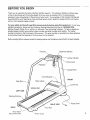
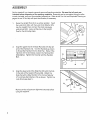
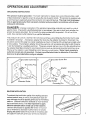
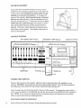
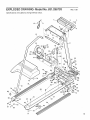
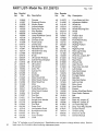
TM
rPROGRAMMABLE
SPEED
rAUTOINCLINE
Model No. 831.296703
Serial No.
I
rial Number
Decal
QUESTIONS?
As a manufacturer,
we are
committed to providing you
complete customer satisfaction. ff you have questions,
or find there are missing or
damaged parts, we will
guarantee
you complete
satisfaction
through direct
assistance from our factory.
TO AVOID UNNECESSARY
DELAYS, PLEASE CALL
DIRECT
TO OUR TOLL-FREE
CUSTOMER
HOT LINE.
The trained technicians on
our Customer Hot Line will
provide immediate assistance, free of charge to you.
CUSTOMER
HOT LINE:
1-800-999-3756
Mon.-Fri.,
6 a.m.-6 p.m. MST.
CAUTION:
Read all safety
and instructions
precautions
in this man-
ual carefully before using
this equipment.
Save this
manual for future reference.
SEAIRS
OWNER'S MANUAL
FULL 90 DAY WARRANTY ON PARTS
For 90 days from the date of purchase,
when proper assembly
and maintenance
procedures
detailed in the Owner's Manual are followed, Sears will, free of charge, repair or replace
install a replacement
part for any defective part, when the Programmable
Speed, Auto
Incline Treadmill is used in a normal manner.
This warranty
for commercial
does not apply when the Programmable
Speed,
Auto Incline Treadmill
and
is used
or rental purposes.
SERVICE IS AVAILABLE
CENTER!DEPARTMENT
BY SIMPLY CONTACTING
IN THE UNITED STATES.
This warranty gives you specific
from state to state.
SEARS,
ROEBUCK
YOUR NEAREST
SEARS
SERVICE
legal rights, and you may also have other rights which vary
AND CO., DEPT. 731CR-W,
CHICAGOI
1L 60684
m
TM
rAUTOINCLINE
rPROGRAMMABLE
SPEED
TABLE OF CONTENTS
Warranty .............
_ .........................
Important Safety Precautions ......................
Before You Begin ...............................
Assembly
.....................................
Operation and Adjustment
............
Trouble-Shooting
and Maintenance
......
Conditioning
Guidelines
..........................
Part List .......................................
: ...........
, ..........
Exploded Drawing ..............................
Ordering Replacement
Parts ......................
WARNING:
Before
beginning
2
4
5
6
7
10
13
14
15
Back Cover
this or any exercise
program
consult
your
physician.
is especially
important
for individuals
over the age of 35 or persons with pre-existing
health
problems.
Read all instructions
before using.
Sears assumes
no responsibility
for personal
injury or property
damage sustained
by or through
the use of this product.
This
3
IMPORTANT SAFETY PRECAUTIONS
WARNING:
following
1.
important
Position
treadmill.
operate
.
To reduce
safety
the treadmill
the risk of burns,
precautions
on a level surface,
Do not place the treadmill
where aerosol
Plug the power
products
cord directly
fire, electric
and information
shock or injury to persons,
before
operating
with at least 8 feet of clearance
on thick carpet,
into a grounded
behind
near water or outdoors.
are used or where oxygen
circuit carrying
read the
the treadmill.
the
Do not
is being administered.
12 or more amps.
No other
appliance
should be on the same circuit. (See the OPERATION
AND ADJUSTMENT
section
of this manual for proper grounding
instructions.)
Keep the power cord away from heated
surfaces.
If an extension cord is required,
use only a 14-gauge, general-purpose
cord of
approximately
five feet in length
with
a three-wire
conductor.
3.
Never move the walking belt while the power is turned off. Do not operate the treadmill
if
the power cord or plug are damaged, or if the treadmill is not working properly.
(Refer to
the BEFORE YOU BEGIN section of this manual if the treadmill
is not working property.)
4.
The roller guards
roller guards,
.
6.
must be 1/8 inch from
.
10.
when
while you are standing
exercising
the
on the walking
belt.
Always
hold the
on the treadmill.
Never allow more than one person on the treadmill at a time. Use the treadmill only as
described in this manual.
Keep small children away from
unattended while it is running.
the treadmill during operation.
Never leave the treadmill
Always turn the power off when the treadmill
is not in use.
Never
into any opening.
Always
drop or insert any object
unplug
the power cord before
procedures
described
do so by an authorized
manual
11.
off and adjust
Wear appropriate
exercise attire when using the treadmill.
Do not wear loose clothing that
could become caught in the treadmill.
Always wear running or aerobic shoes. Never use
the treadmill with bare feet, wearing only stockings, or in sandals.
Athletic support clothes
are recommended
for both men and women.
handrail
.
Turn the power
if necessary.
Never start the treadmill
1
the rear roller.
should
This treadmill
performing
the maintenance
and adjustment
in this manual. Never remove the motor hood unless instructed to
service representative.
Servicing other than the procedures
in this
be performed
is capable
by an authorized
of high speeds.
speed.
SAVE THESE INSTRUCTIONS
service representative
Adjust
only.
the speed slowly to avoid sudden
jumps
in
BEFORE YOU BEGIN
Thank you for selecting the Sears Lifestyler 3500ps treadmill. The Lifes_ter 3500ps combines
of-the-art technology with innovative design to let you enjoy an excellent form of cardiovascular
state-
exercise at your convenience,
in the privacy of your home. Your exercise on the Lifestyler 3500ps will
be enhanced by such features as a key-activated
power switch, electronic speed control, auto incline
control, and a programmable
console:
For your safety and benefit, read this manual carefully before using this equipment.
If you have
additional questions, please call our Customer Service Department toll-free at 1-800-999-3756,
Monday through Friday, 6 a.m. until 6 p.m. Mountain Time (excluding holidays). To help us assist you
quickly, please mention your product model number and serial number when calling. The model
number is printed on the front cover of this manual. The serial number
to the product (see the drawing on the front cover for the location).
Before reading
further, please
review the drawing
below and familiarize
Console
_.
is recorded
yourself
/
on a decal attached
with the parts labeled.
Electronic
Monitor
Incline Indicator
:line Lever
/
Handrail
/
ht Post
Circuit Breaker
FRONT
Side
Motor Hood \
Knob
Walking
Belt
LEFT SIDE
Walking Platform \
\
RIG HT SIDE
Power
Cord
\ Foot Rail
BACK
Rear Roller
Adjustment
Bolts
\' Roller Guard
5
ASSEMBLY
Set the treadmill in a cteared area and remove all packing materials.
Be sure that all parts are
included
before disposing
of the packing
materials.
Assembly can be completed using the allen
wrench included, and your own standard screwdriver.
Refer to the Part List and Exploded Drawing on
pages
.
14 and 15 for help with part identification,
if necessary.
Raise the Upright Post (9) to a vertical position.
Insert
the Lock Knob (38), with the Lock Knob Washer (37),
into the Upright Post, and turn the Knob clockwise
until almost tight. Leave a little play in the Upright
Post for the following steps.
37
.
Align the upper end of the Side Rail (72) with the left
end of the Handrail (14). Turn the Handrail as shown
to thread the Handrail into the Side Rail. (Note: If the
Handrail will not turn easily, loosen the Handrail Bolt
[16] slightly.) Tighten the Handrail and the Handrail
Bolt.
,
Align the lower end of the Side Rail (72)with the hole
in the side of the treadmill Frame (58). Attach the
Side Rail with a Side Rail Bolt (70), Formed Washer
(71) and Side Rail Washer
Lock Knob (see step 1).
(73) as shown:
Tighten the
7O
73
Make sure that all parts are tightened
using the treadmill.
6
securely
before
71
58
38
OPERATION
GROUNDING
AND ADJUSTMENT
INSTRUCTIONS
This product
must be grounded.
If it should malfunction or break down, grounding provides a path
of least resistance for electric current to reduce the risk of electric shock. This product is equipped with
a cord having an equipment-grounding
conductor and a grounding plug. The plug must be plugged
into an appropriate
outlet that is properly installed
and grounded
in accordance
with all local
codes and ordinances.
DANG ER:
improper connection of the equipment-grounding conductor can result in a risk of
electric shock. Check with a qualified electrician Orserviceman if you are in doubt as to whether the
product is properly grounded. Do not modify the plug provided with the product - if it will not fit the
outlet, have a proper outlet installed by a qualified electrician.
This product is for use on a nominal 120-volt circuit, and has a grounding plug that looks like the plug
illustrated in Drawing 1. A temporary adapter that looks like the adapter illustrated in Drawing 2 may
be used to connect this plug to a 2-pole receptacle as shown in Drawing 2 if a properly grounded outlet
is not available.
The temporary adapter should be used only until a properly grounded outlet (Drawing
1) can be installed by a qualified electrician.
The green colored rigid ear, tug, or the like extending from
the adapter must be connected to a permanent ground such as a properly grounded outlet box cover.
Whenever the adapter is used it must be held in place by a metal screw. Some 2-pole receptacle
outlet box covers are not grounded.
Contact a qualified
electrician
to determine
if the outlet
box cover is grounded
before using an adapter.
Grounded
Outlet
Grounding
Box
2
Grounded
Outlet
Box
Plug
Grounding
+ounding Pit
ted Outlet
SILICONE
APPLICATION
To maintain the low-friction quality of the walking belt and
reduce treadmill wear, a non-oil, non-petroleum
base silicone lubricant should be applied generously to the walking
platform. (Silicone lubricant is available at most hardware
and automotive stores.) It is very important
to apply
silicone lubricant
before initial use of the treadmill.
Lubricant should
use or whenever
also be applied after every 10 hours of
a decrease in performance
is noticed.
Unplug the power cord, lift each side of the walking belt
and apply the lubricant generously to the area indicated.
Plug
INCLINEADJUSTMENT
Tovary the level of exerciseintensity,the inclineof the
treadmillcan be changedusingthe leveron the right side
of the console. Do not adjust the incline while you are
walking or running on the treadmill. Toincreasethe
inclineof the treadmill,stand toward the rear of the foot
rails and pull backthe lever. Whenthe desiredinclineis
reached,releasethe lever. Todecreasethe incline,stand
toward the front of the foot rails, lean forward if necessary, and pull back the lever until the desired incline is
reached.
There is an incline indicator located above the
incline
lever on the console.
The indicator
measures
the
incline of the treadmill.
CONSOLE
D_AGRAM
MAX SPEED
SET Display
l SEGMENT
[--PROGRAM
SEGMENTS
T'MER
Display
[ Electronic
Disp!ay._
_.x-I1x-t -
-- -
ii
ia la n I
H I
I
, PROGRAM
: STOP
USER Keys
THE POWER
'lI
B § H
mm
TURNING
Monitor
START
Key
Key
MANUAL Key
Clip
ON
Stand on the foot rails of the treadmill.
Attach the clip on the safety key to the waistband of your
clothing. CAUTION:
Always wear the clip when operating the treadmill.
If you fall while exercising,
the safety key will be pulled from the console, instantly turning the power off.
Insert the safety key into the power switch in the front of the console. The electronic monitor display
will turn on, the indicator on the MANUAL key will light and one bar in the SPEED ADJUST display will
light. NOTE: If you remove the safety key from the console,
cessor to power down before re-inserting the key.
ELECTRONIC
8
MONITOR
See the Electronic
wait for ten secondsfor
OPERATION
Monitor Operation
Guide accompanying
this manual.
the micropro-
MANUAL
SPEED
MODE
When the power is turned on, the console will be in the manual mode and the walking belt will be
stationary. The speed of the walking belt can be controlledwith
the plus (+) and minus (-) keys in the
SPEED ADJUST display. Each time the plus key is pressed, a tone will sound and the speed of the
walking belt will increase.
Every fourth time the key is pressed, an additional bar in the display wi!l
light. The minus key functions in the same manner to decrease the speed. (The keys can be held
down to change the speed quickly.) CAUTION:
It will take a few seconds for the walking belt to reach
the selected speed. Adjust the speed gradually until you are familiar with the treadmill.
Press the plus key until the walking belt begins to move at slow speed. Step carefully onto the walking
belt and begin exercising.
Adjust the speed as desired by pressing the plus or minus keys.
To stop the walking
pressing
belt, hold down the minus key. The belt can be stopped
the STOP key.
PROGRAMMABLE
It will take a few seconds
SPEED
quickly, if desired,
by
for the belt to stop fully.
MODE
When the console is in the programmable
mode, the speed of the walking belt will be controlled
automatically
by workout programs you create. Up to four workout programs can be stored in memory,
and recalled for future workouts.
To create a program,
first press one of the four USER keys.
Next, press the plus (+) or minus (-) keys
in the MAX SPEED SET display to set the maximum speed you want the walking belt to move during
the program.
Each time one of the keys is pressed, the maximum speed setting will change by 0.5
miles per hour. The maximum speed setting must be at least 4.0 miles per hour. (The maximum
speed
setting cannot be set quickly
by holding down the keys.)
Ten speed settings should now be programmed
on the PROGRAM SEGMENTS display. The display
is divided into ten vertical segments, each with a plus (+) and minus (-) key and eight bars. One speed
setting can be programmed
on each segment.
The bars in each segment show the speed setting of
that segment.
If one bar is lighted, the segment is PrOgrammed for the minimum speed. If all eight
bars are lighted, the segment is programmed
for the maximum speed. (If a program has not previously
been created, four bars will be lighted in each segment.)
To program a speed setting on the first
segment (at far left), press the plus or minus keys in that segment.
Each time the plus key is pressed,
a tone will sound and the speed setting will increase. Every fourth time the plus key is pressed, an
additional
speed
setting
on the
setting
bar in the segment
will light. The minus key functions
in the same manner to decrease
the
setting. (The keys can be held down to program a speed setting quickly.) Program speed
s on the remaining nine segments in the same manner. You may wish to program a low setting
first segment for awarm-up,
a combination of higher settings on the middle segments, and a low
on the final segment for a cool-down.
An endless variety of "profiles" can be created.
Next, press the plus (+) or minus (-) keys in the SEGMENT TIMER display to set the length of time you
want each segment to last. (All segments will last for the same length of time.) Each segment can be
set to last for a minimum of 30 seconds, up to a maximum of 9 minutes, 50 seconds.
Each time one of
the keys is pressed,
the time quickly.)
To start the program,
the time displayed
wit! change
press the PROGRAM
to flash, and after a few seconds
segment. Step onto the walking
by 10 seconds.
(The keys can be held down to set
START key. The lighted bars in the first segment
will begin
the walking belt wilt begin to move at the speed setting of the first
belt and begin exercising.
The SEGMENT TIMER display will show
the time remaining in the first segment.
When no time remains, the lighted bars in the second segment
will begin to flash, the speed of the walking belt will change to the setting of the second segment, and
the SEGMENT TIMER display will show the time remaining in the second segment.
After allten segmentshavebeencompleted,the walkingbelt witlslow to a
stop and the program will
end. Note: If you wish to stop the walking belt before the program has ended, press the STOP key.
The console will then be in the same state as if the program had ended,
IMPORTANT:
If you want to change
any program
settings
after the program
has been started, press
the STOP key, and then make the desired changes.
The program can be restarted by pressing the
PROGRAM START key. Changing settings while the program is running could cause the speed of the
walking belt to increase suddenly.
After the program
has ended, the program
can be restarted,
a different
program
can be selected
by
pressing one of the other USER keys or the console can be switched to the manual mode by pressing
the MANUAL key. When the console is switched to the manual mode, or the power is turned off, the
current settings of the ten segments will be stored in memory. Programs will be stored as long as the
power cord remains plugged in. When the power cord is unplugged,
programs
will be erased,
TURNING
THE POWER
OFF
To turn the power off, remove the safety key from the console. Store the safety key in a secure location to prevent small children from operating the treadmill.
NOTE: After removing the safety key from
the console, wait for ten seconds for the microprocessor
to power down before re:inserting the key.
TROUBLE-SHOOTING
AND MAINTENANCE
Most treadmill problems can be solved by following
the simple steps below.
Find the symptom
that applies, and follow the steps listed. If further assistance is necessary, please call our Customer
Service Department toll-free at 1-800-999-3756,
Monday through Friday, 6 a.m, until 6 p.m. Mountain
-tqme (excluding holidays).
1. SYMPTOM:
a.
C.
DOES NOT TURN
ON
Make sure the power cord is plugged into a properly grounded outlet. (See OPERATION AND
ADJUSTMENT
in this manual.)
If an extension cord is necessary, use only a 14-gauge, general
• purpose
b.
THE POWER
cord of approximately
five feet in length.
Make sure the safety key is fully inserted into the console. Various indicators
should light. (See OPERATION AND ADJUSTMENT
in this manual.)
Check the circuit breaker
located on the treadmill
on the console
frame
near the power cord. If the switch protrudes as shown,
the circuit breaker has tripped. To reset the circuit
breaker, wait for five minutes and then press the switch
back in.
3"ripped
10
Reset
2. SYMPTOM:
a.
THE POWER
TURNS
OFF DURING
Check the circuit breaker located on the treadmill frame near the power cord. If the switch
protrudes, the circuit breaker has tripped. To reset the circuit breaker, wait for five minutes
then pl'ess the switch back in. (See the drawing
b.
Make sure the power cord is plugged
c.
Remove the safety key from the console.
fully into the console.
3. SYMPTOM:
a.
Various
THE ELECTRONIC
4. SYMPTOM:
THE CONSOLE
DOES NOT FUNCTION
5. SYMPTOM:
THE PULSE
PROPERLY
Guide:)
UP
from the console,
EARCLIP
light.
the two screws attaching the electronic monitor and gently
Make sure the power and speed wires are plugged fully into
Monitor Operation
LOCKS
and then reinsert the safety key
on the console should
Unplug the power cord, wait for 10 seconds,
safety key is removed
above.)
Wait for ten seconds
MONITOR
(See the Electronic
and
in.
indicators
Using a small screwdriver, remove
pry the monitor out of the console.
the monitor.
a.
USE
and plug the power cord back in. Each time the
wa t for 10 seconds
DOES NOT FUNCTION
before reinserting
the key.
PROPERLY
a. Make sure the pulse earclip is plugged fully into the electronic monitor. Attach the clothes clip to
your collar. Rub your left ear lobe and reposition the earclip.
b.
Try standing still while measuring your pulse. The pulse earclip is not a medically
device. External factors such as movement may affect heart rate readings.
c.
The pulse
earclip
may need to be cleaned.
circles inside the earclip,
6. SYMPTOM:
a.
Co
using a cotton swab saturated
BELT SLOWS
open, and wipe the two clear
with denatured
WHEN WALKED
alcohol,
ON
Silicone lubricant should be applied to the walking platform before use. Lubricant should b_
reapplied after every 10 hours of use, and whenever a decrease in performance is noticed. UNI
SPORT Silicone Spray is recommended.
CAUTION:
ALWAYS TURN THE POWER OFF
WHEN APPLYING LUBRICANT.
(See OPERATION AND ADJUSTMENT
in this manual for
application
b.
THE WALKING
Press the earclip
certified
instructions.)
If an extension cord is necessary,
five feet in length.
use only a 14-gauge
general-purpose
cord of approximately
If the walking belt is overtightened,
treadmill performance may be reduced.
TURN THE POWER OFF.
Turn both rear roller adjustment bolts counterclockwise,
1/4 of a turn. Repeat as necessary until the tension of
the walking belt is correct: When the tension is correct,
you should be able to lift each side df the walking belt
2-3 in. off of the walking platform.
The center of the
walking belt should remain just at the surface of the
walking platform.
Be careful to keep the walking belt
centered on the walking platform.
11
7. SYMPTOM:
THE WALKING
BELT IS OFF-CENTER
If the walking belt has shifted to the left, first TURN
a.
OR SLIPS WHEN WALKED
ON
THE
POWER OFF. Turn the left rear roller adjustment bolt
clockwise, and the right bolt counterclockwise,
1/4 of a
turn each. Repeat as necessary until the walking belt is
centered.
b.
If the walking belt has shifted to the right, first TURN
THE POWER OFF. Turn the left rear roller adjustment
bolt counterclockwise,
and the right belt clockwise,
of a turn each. Repeat as necessary
belt is centered.
until the walking
If the walking
belt slips when walked on, first TURN
THE POWER
OFF. Turn both rear roller adjustment
c.
1/4
bolts clockwise, 1/4 of a turn. Repeat as necessary until
the tension of the walking belt is correct. When the
tension is correct, you should be able to lift each side of
the walking belt 2-3 in. off of the walking platform.
The
center of the walking belt should remain just at the
surface of the walking platform.
Be careful to keep the
walking belt centered on the walking platform.
8. SYMPTOM:
a.
DOES NOT INCLINE
Stand at the back of the foot rails while increasing the incline. Stand at the front of the foot rails
and lean forward while decreasing the incline. (See OPERATION AND ADJUSTMENT
in this
manual.)
9. SYMPTOM:
a.
THE TREADMILL
THE INCLINE
INDICATOR
NEEDS
ADJUSTMENT
Lower the treadmill fully. (See OPERATION
AND ADJUSTMENT
adjustment instructions.)
Gently press the ends of the indicator,
until the bubble in the indicator shows level 1.
in this manual for incline
using a pen or similar object,
STORAGE
Always
position,
washers
unplug the power cord when the treadmill
the treadmill
to the storage
first remove the bolt and washers from the lower end of the side rail. Keep the bolt and
in a secure location. Remove the side rail from the handrail. Loosen the lock knob and lower
the upright
12
is not in use. To convert
post onto the walking
belt. Lay the side rail on the treadmill.
EXPLODED DRAWING'
Specifications
are subject
to change
Model No. 831.296703
without
Rev. 11/£1
notice.
13
14
15
32
38
39
76
75
4O
55
29
74
5_:
56
73
\
20 84
52
51
57
58
2O
63
59
\
61
15
PART LIST- Model No. 831.296703
14
Key
Reorder
Key
No.
No.
Qty.
1
2
3
104546
104327
013509
4
5
6
7
Rev.
11/91
Reorder
Description
No.
No.
Qty.
1
1
2
Console
Electronic Monitor
Monitor Screw
46
47
48
013275
014063
012108
1
3
2
Front Roller Adj. Bolt
Adjustment Washer
Wheel Nut
088015
106593
102250
088005
1
I
1
1
Incline Indicator
Safety Key/Clip
Wire Harness
Incline Cable
49
50
51
52
102214
013399
052014
012179
1
2
2
2
Incline Leg
Wheel Mounting
Wheel
U-Nut
8
102249
I
Jump Wire/Motor
53
100691
6
Platform
Control
Description
Bolt
Bolt
9
102103
I
Upright Post
54
104533
1
Safety
10
11
12
13
104626
101508
054013
102116
5
1
1
1
Console Screw
Pulse Earclip
Clothes Clip
Side Rail Foam Grip
55
56
57
58
102599
102100
053025
NSP
1
1
1
1
Front Roller/Pulley
Walking Belt
Walking Platform
Frame
14
15
101941
102107
1
1
Handrail/Foam
Handrail Foam Grip
59
60
107406
040156
1
2
Right Foot Rail
Rear Leg Endcap
16
17
18
19
013496
054016
088004
008149
1
1
1
1
Handrail Bolt
E-Clip
Lift Cylinder Release
Cylinder Mount Bracket
61
62
63
64
101362
102248
010206
070084
1
1
2
1
Right Endcap
White AC Jumper,
Roller Guard
Rear Roller
20
21
013162
059019
28
1
Small Screw
Lift Cushion
65
66
016028
045010
1
1
Wrench Clip
Allen Wrench
22
23
24
25
26
27
043036
106334
015045
031238
101757
013445
1
1
1
1
1
4
Lift Cylinder
Cotter Pin
Cylinder Pin
Choke
Controller
Motor Mount Bolt
67
68
69
70
71
72
013206
101361
040201
106279
014094
101942
2
1
1
1
1
1
Rear Roller Adj. Bolt
Left Endcap
Side Rail Endcap
Side Rail Bolt
Formed Washer
Side Rail
28
29
30
101630
012082
101629
4
5
1
Motor Mount Washer
Motor Mount Nut
Motor
73
74
75
014086
107405
103585
1
1
1
Side Rail Washer
LeftFoot
Rail
Motor Hood
31
103321
1
Jump Wire
76
013586
4
Hood Screw
32
33
100147
102087
1
1
Pulley/Flywhee!/Fan
Motor Mount Bracket
77
78
033066
100335
1
1
Magnet
Sensor Wire/Reed
34
35
36
104624
012037
014101
2
1
2
Shaft Bolt
Pivot Nut
Pivot Washer
79
80
81
062035
101004
019084
1
1
1
Reed Switch
Belt
Grommet
37
38
39
40
41
014156
017103
013543
031229
107816
1
1
1
1
1
Upright Knob Washer
Upright Knob
Pivot Bolt
Power Cord
Link/Isolation
Board
82
83
84
85
86
102247
102246
013303
102115
014041
1
1
2
2
1
Black AC Jumper, 2F
White AC Jumper, 2F
Uft Frame Mtg. Bolt
Snap Track Mtg. Bracket
Tension Washer
42
43
44
45
008148
016055
031036
103855
4
4
1
1
Hood Mount Anchor
Wire Clip
Circuit Breaker
J-Bolt
87
#
#
104514
089036
107772
1
1
1
Tension Spring
Electronic Guide
Owner's Manual
Note:- "#" indicates a non-illustrated
part. Specifications
are subject to change
back cover for information about ordering replacement parts.
Cover
without
M/F
Switch
Fastener
notice.
See the
EXPLODED DRAWING= Model No. 831.296703
Specifications
are subject
to change
without
Rev. 11/91
notice•
14
10.
15
32
29
19
2(
i. J
25
I
i
221
I 35
"'-._.33
38
I
I
39
I
_--,..83
144...j_
"'1.
,I_
78"_L
43
-
4O
75
29
74
5,_
72
49
70.
56
73
69
20 84
52
51
57
2O
_63
58
63
59
67
.
61
15
' J ,RS SERVlCE
ORDERING
is at YOUR SERVICE
REPLACEMENT
PARTS
Each TREADMILL
has its own MODEL
requesting
or repair parts for your TREADMILL.
service
All parts listed herein may be ordered
most SEARS RETAIL STORES.
NUMBER.
through
Always
SEARS,
mention this MODEL
ROEBUCK
AND CO. SERVICE
If parts you need are not stocked locally, your order will be electronically
PARTS DISTRIBUTION
CENTER for expedited handling.
WHEN
ORDERING
1. The MODEL
REPAIR
NUMBER
PARTS, ALWAYS
of the product
2. The NAME of the product (Sears
3. The REORDER
NUMBER
4. The DESCRIPTION
transmitted
GIVE THE FOLLOWING
when
CENTERS
and
to a SEARS
INFORMATION:
(831.296703).
Lifestyler
of the part(s)
of the part(s),
NUMBER
3500ps
Treadmill).
from page 14 of this manual.
from page 14 of this manual.
Your Sears merchandise
has added value when you consider that Sears has service units nationwide
staffed with Sears trained technicians specifically trained on Sears products, having the parts, tools
and the equipment
to insure that we meet our pledge to you: we service
SOLD
ROEBUCK
BY SEARS,
Part No.'107772
11/91 Printed
AND CO., CHICAGO,
in U.S.A. @1991 Sears,
what we sell.
IL 60684
Roebuck
and Co.