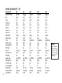
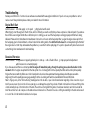
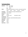
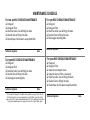
1
COMPETITION SERIES
ENGINES
*NOT EPA COMPLIANT
ULTIMA COMPANY LLC
Ultima Company LLC is not a representative of any other motorcycle manufacturer and the parts we sell are not necessarily recommended by any other
motorcycle manufacturer.
All words used in this catalog denoting any motorcycle manufacturer, models or motorcycle, or part numbers are intended for use as reference only.
Although our replacement engines are not original factory equipment for some manufacturers, our intention is to provide an exceptional quality
replacement part that will outperform the original equipment of many OEM manufacturers.
Harley-Davidson® Parts: Harley® and Harley-Davidson® and other model names of Harley® motorcycles are used as a reference only. Some H-D®
part numbers are also used as reference only. We are not an authorized Harley® dealer and in no way do we have, or intend to imply any kind of business
relationship with Harley-Davidson Motor Company®. Our intention is to provide products that can be used on a Harley-Davidson® motorcycle.
Names and words that are registered trademarks of Harley-Davidson® Inc. Milwaukee, WI, such as Evolution®, Harley-Davidson®, Harley®, H-D®,
HD®, and Softail® are not intended to imply that they are Harley-Davidson® original equipment by their use in connection with Harley-Davidson®
factory part numbers.
The following model designations for Harley-Davidson® motorcycles are used in this catalog for reference only: EL, FL, FLH, FLHR, FLHS, FLHT, FLHTC,
FLHTC-I, FLHTC Ultra Classic, FLHX, FLST, FLSTC, FLSTF, FLSTN, FLSTS, FLT, FLTC, FLTC Ultra Classic, FXB, FXD, FXDB, FXDC, FXDG, FXDL, FXDS, FXDSConv., FXDWG, FXE, FXEF, FXLR, FXR, FXRC, FXRD, FXRDG, FXRP, FXRS, FXRSE, FXRS-Conv., FXRS-SP, FXRT, FXS, FXSB, FXST, FXSTC, FXSTS, FXSTSB,
FXWG, GE, K, KH, WL, WLA, XL, XLCH, XLCR, XLH, XLH 883, XLH 1100, XLH 1200, XLR, XLS, XLT, XLX AND XR-1000.
All other trademarks, registered trademarks and brand names used in this catalog are the property of their respective holders.
WARNING
Serious injury, death and property damage can result from the improper use, control, alteration, or maintenance of motorcycles. The dealer and dealers
customers must exercise good judgement in the use, control, alteration, part selection and installation, and maintenance of motorcycles. Ultima® has
no control over the judgement of others and assumes no responsibility or liability of any nature for the failure of others to use good judgement.
COPYRIGHT ULTIMA® COMPANY LLC 2008
REV 08/01/08
1
ULTIMA® COMPETITION SERIES ENGINES
DISTRIBUTED EXCLUSIVELY BY MIDWEST MOTORCYCLE SUPPLY
Failure to read and comply with this document completely may Void Warranty.
COMPETITION SERIES ENGINE WARRANTY:
Ultima’s Complete Assembled Competition Series engines are guaranteed to the original purchaser to be free of manufacturing defects in
materials and workmanship for a period of 12 months from the date of purchase on 80, 96, 100, 107 & 113 CI Engines & 6 months from the date
of purchase on 120 and 127 CI Engines configurations.
All Unassembled Engines and Long Blocks are guaranteed to the original purchaser to be free of manufacturing defects in materials and
workmanship for a period of 12 months from the date of purchase.
Merchandise that fails to conform to these conditions will be repaired by Ultima if the parts are returned to Midwest Motorcycle Supply by the
purchaser within the specified warranty period or within 10 days thereafter. Cost associated with removing or installation of complete engines
are not covered under this warranty. This warranty covers Ultima® parts only and no other associated expenses.
In the event that any warranty service is required, the original purchaser must call or write Midwest Motorcycle Supply immediately with the
problem. Many problems can be rectified by a telephone call and need no further course of action. Merchandise that is suspected of being
defective must not be replaced by a Dealer or End User without prior authorization from Midwest Motorcycle Supply. If it is deemed necessary
for Ultima to make an evaluation to determine whether the part was defective, it must be packaged properly to prevent further damage and be
returned prepaid to Midwest Motorcycle Supply. You must include a copy of the original invoice and a detailed letter outlining the nature of the
problem. You must also outline how the part was used and the circumstances at the time of failure. If, after an evaluation has been made by
Ultima and the part was found to be defective, repair to the existing part or replacement will be granted at Ultima’s discretion. Engines that
have been modified in any way from the original purchased configuration will have the warranty void.
For any warranty issues please contact: Ultima Company LLC • 2100 Highway Z, Pevely, MO 63070 • 314-773-3064 • [email protected]
2
LONG ROD SERIES ENGINES 130 & 140 CI
Ultima’s Complete Assembled, Unassembled and Long Blocks in the Long Rod Series of Engines have no warranty expressed or implied,
however, engines that are suspect of being defective may qualify for limited warranty assistance. Due to the nature of these engines ultimate
use and performance level we feel it is impossible to express a comprehensive warranty and any claims will be handled strictly at Ultima’s
discretion.
ENGINE COMPONENTS
All of Ultima’s individual engine components or kits including long blocks, fuel systems and ignition systems are covered by a 12 Month
Warranty. This warranty covers part replacement only and no other associated expenses. In the event that any warranty service is required,
the original purchaser must call or write Midwest Motorcycle Supply immediately with the problem. Many problems can be rectified by a
telephone call and need no further course of action. Merchandise that is suspected of being defective must not be replaced by a Dealer or End
User without prior authorization from Midwest Motorcycle Supply. If it is deemed necessary for Ultima to make an evaluation to determine
whether the part was defective, it must be packaged properly to prevent further damage and be returned prepaid to Midwest Motorcycle
Supply. You must also include a copy of the original invoice and detailed letter outlining the nature of the problem. You must also outline how
the part was used and the circumstances at the time of failure. If, after an evaluation has been made by Ultima and the part was found to be
defective, repair to the existing part or replacement will be granted at Ultima’s discretion.
ADDITIONAL WARRANTY PROVISIONS:
1. Ultima® shall have no obligation in the event an Ultima® part is modified by any other person or organization.
2. Ultima® shall have no obligation in the event an Ultima® part becomes defective in whole or in part as a result of improper installation,
improper maintenance, improper use, abnormal operation, or any other misuse or mistreatment of the Ultima® part.
3. Ultima® shall not be liable for any consequential or incidental damage resulting from the failure of an Ultima® part, the breach of any
warranties, the failure to deliver, delay in delivery, delivery in non-conforming condition, or for any other breach of contract or duty between
Ultima® and a customer.
4. Ultima® parts are designed exclusively for use in Harley-Davidson® type motorcycles. Ultima® shall have no warranty
or liability obligation if an Ultima® part is used in any other application.
3
General Specifications 80” - 113”
4
Displacement CI
Displacement CC/CI
80Ci
1340/81.8
96Ci
1564/95.5
100Ci
1643/100.2
107Ci
1751/106.8
113Ci
1853/113.1
Bore
Stroke
Compression
Valve : Int
Valve: Ex
Cam Lift: Int
Cam Lift: Ex
Cam Duration
Pushrod Length
Piston
Cylinder Length
Case Deck Height
Rod Length
Flywheel
Case Spigot bore
Pump Type
Breather Type
Cam Cover Type
Rocker Box Type
Rocker Arm/ Ratio
Engine Height
Rated power RW
Engine Weight
3.498”
4.25”
8.75:1
1.850”
1.625”
.490”
.490”
242/252
Stock
Cast
5.550
5.375
7.44
Forged 5 Pc
3.680”
92/L
92/L (NOTE 1)
84/89
93/L
1.63
Stock
75hp/80 tq
145 Lb
3.625”
4.625”
9.8:1
1.850”
1.625”
.520”
.520”
262/272
Stock
Forged
5.565
5.375
7.44
Forged 5Pc
3.880”
92/L
92/L (NOTE 1)
84/89
93/L
1.63
.015” Taller
100hp/100tq
150 Lb
3.875”
4.250”
9.6:1
2.100”
1.700”
.625”
.600”
248/252
Stock
Forged Dome
4.995
5.875
7.44
Forged 5Pc
4.255”
92/L
92/L (NOTE 1)
84/89
93/L
1.7
.010” Taller
110hp/110tq
165 Lb
4.000”
4.250”
10:1
2.100”
1.700”
.625”
.600”
248
Stock
Forged Dome
4.995
5.875
7.44
Forged 5Pc
4.255”
92/L
92/L (NOTE 1)
84/89
93/L
1.7
.010” Taller
115hp/115tq
165 Lb
4.000”
4.500”
10.2:1
2.100”
1.700”
.640”
.600”
264/268
Stock
Forged Dome
4.995
5.875
7.44
Forged 5Pc
4.255”
92/L
92/L (NOTE 1)
84/89
93/L
1.7
.010” Taller
120hp/120tq
165 Lb
NOTE (1)
Ultima® engines are
supplied with 93/L
breathers operating
but the early 84/92
system is present
but plugged.
General Specifications
Displacement CI
Displacement CC/CI
120 Ci
1976/120.6
127 Ci
2092/127.7
130Ci
2118/129.3
140 Ci
2305/140.6
Bore
Stroke
Compression
Valve : Int
Valve: Ex
Cam Lift: Int
Cam Lift: Ex
Cam Duration
Pushrod Length
Piston
Cylinder Length
Case Deck Height
Rod Length
Flywheel
Case Spigot bore
Pump Type
Breather Type
Cam Cover Type
Rocker Box Type
Rocker Arm/ Ratio
Engine Height
Rated power RW
Engine Weight
4.250”
4.250”
9.8:1
2.100”
1.700”
.640”
.600”
264/268
+.250 Longer
Forged Flat
5.030
5.975
7.700”
Forged 3 Pc
4.500”
92/L
92/L (NOTE 1)
84/89 Ultima®
93/L
1.7
.125” Taller
130hp/135tq**
168 lb
4.250”
4.50”
10.2:1
2.100”
1.700”
.640”
.600”
264/268
+.250 Longer
Forged Flat
5.030
5.975
7.700”
Forged 3 Pc
4.500”
92/L
92/L (NOTE 1)
84/89 Ultima®
93/L
1.7
.125” Taller
140hp/145tq**
168 lb
4.400
4.250
10.0:1
2.300”
1.800”
.640”
.600”
264/268
+.500 Longer
Forged Flat
5.340
6.152
8”
Forged 3 pc
4.625”
92/L
92/L (NOTE 1)
84/89 Ultima®
93/L Billet Reed Valve
1.7
.625” Taller
150hp/160tq**
170 lb
4.400”
4.625”
10.8:1
2.300”
1.800”
.640”
.600”
264/268
+.500 Longer
Forged Flat
5.340
6.152
8”
Forged 3 Pc
4.625”
92/L
92/L (NOTE 1)
84/89 Ultima®
93/L Billet Reed Valve
1.7
.625” Taller
160hp/175tq**
170 lb
NOTE (1)
Ultima® engines are supplied with
92/L breathers operating but the
early 84/91 system is present but
plugged.
** Horsepower ratings on 120, 127
and 140 will be lower if the ‘G’
Carb or 45mm Mikuni is used without
modification or replaced by a larger
bore Carburetor. Horsepower ratings
on all Engines will also be greatly
affected by Exhaust systems selected.
5
Cam Information All Models
96 CI engines: MW 520 Cam
Timing information is Open/Close @ .053
Int 28/54
262 Dur
Lift .520
TDC .209
Ex 69/23
272 Dur
Lift .520
TDC .194
Lobe Sep 108
Overlap 51
100 and 107 CI engines: MW 248 Cam (1.69 rocker arm ratio)
Timing information is Open/Close @ .053
Int 18/50
248 Dur
Lift .625
TDC .181
Ex 54/18
252 Dur
Lift .600 TDC .171
Lobe Sep 107
Overlap 36
113-120-127 CI engines: MW 264 Cam (1.69 rocker arm ratio)
Timing information is Open/Close @ .053
Int 24/60
264 Dur
Lift .640 TDC .218
Ex 68/20
268 Dur
Lift .600 TDC .200
Lobe Sep 111
Overlap 44
6
Lobe Center 103
Lobe Center 113
Lobe Center 106
Lobe Center 108
Lobe Center 108
Lobe Center 114
Installation Notes:
Ultima® Engines should be installed by a trained professional mechanic into a motorcycle for which its use was intended. Failure to do so
may result in injury and even death. It is the customer’s responsibility to insure their mechanic has proper training.
Fitment and Clearance Issues:
Every effort has been made to insure these engines will install into most available frame models without modifications. Some of the known
fitment issues we have encountered are listed below. Please read these carefully as they will aid in installation.
Fitment Issues: All Crank Cases
1. Ultima® crank cases are designed to fit most OEM motorcycles built from 1984-1999 using Evolution® style engines. On rubber mounted
engines please check that the front engine mount bracket weld or tab does not interfere with the case before final torque of the engine
mount bolts — clearance the bracket if needed.
2. On most FXR® or bikes using midshift controls it may be necessary to clearance the case for the inner shift arm.
Fitment Issues: Cylinder 100-107-113-120-127 Ci
1. On some frames using offset engines and forward controls it may be necessary to space the inner shift arm or the shifter mounting bracket
away from the front cylinder fins to provide adequate clearance between the shift arm or rod and the cylinder fins.
Fitment Issues: Cylinder Heads 100-107-113-120-127 Ci
1. If installing these engines into a Stock Style Softail® type frames it will be necessary to relocate the coil and bracket.
Fitment Issues: All 130 & 140 Ci
1. The Ultima® 130 Ci and 140 Ci engines are over 5/8” taller than a stock engine. These engines will fit in most Ultima® frames but other
aftermarket manufactured frames must be checked for fitment. All fitment issues for 113Ci thru 127 Ci engines apply to the 130 Ci and 140 Ci.
The Ultima® 130 Ci and 140 Ci will require VERY heavy duty drive train components.
7
CRANKCASE
VENT
Oil Pump Fittings Identification:
®
Ultima engines use a 1992 & later style oil pump as shown in Figure 2.
1. The feed line is mounted in the center of the outer cover of the pump and is
pointing up.
2. The return line is mounted to the very bottom of the outer cover and is pointed
forward. This line goes to the Filter Input. See Figure 5.
3. The Crank case vent is mounted to the engine case just above the oil pump.
4. The feed line can be moved by removing the plug at the bottom of the outer
pump cover and reinstalling the fittings.
OIL FEED
FROM TANK
OIL RETURN
TO FILTER
Oil Line Routing
Figure 3 Tank cutaway shows the oil line identification for Stock FXST® type tanks and
Ultima® brand FXST® type oil tanks.
Figure 4 Tank cutaway shows the oil line identification for Ultima® brand round oil tanks.
As you can see, both tanks have an internal return line that goes to the far side of the
tank to improve oil circulation. If you are using this type of tank you must have the
return line connected to the correct fitting. NEVER ASSUME YOUR OIL TANK IS CLEAN
ENOUGH.
OUTSIDE LINE
VENT
INSIDE LINE (NEAR SEAT
POST) RETURN
FEED LINE POINTS
TOWARD TRANS
8
FIG. 3
THESE LINES
MUST BE
CONNECTED
PROPERLY
TO THE
OIL TANK
AND FILTER
HOUSING
OR
ENGINE FAILURE
CAN
OCCUR!!!
OPTIONAL FEED
LOCATION (NEXT
TO RETURN)
FIG. 2
DRAIN
PLUG
FEED
LINE
RETURN
LINE
VENT
LINE
FIG. 4
Oil Recommendations
For the first 500 miles of operation we recommend using high quality petroleum
based API service SJ rated motor oils, such as Ultima 20W50, MW# 103-114. The
oil’s viscosity should be matched with the climate conditions but in most cases
Ultima 20w50 motor oil will work fine. After initial break-in (over 500 miles) we
recommend using Ultima full synthetic motor oil, MW#103-115.
Oil Filters
All Ultima® engines require oil filters. Oil filter mounting bolts are located on the
right side of the engine case made to accept 92/99 FXST® style filter mounts.
When using this type of filter housing make sure the lines are routed as shown in
Figure 5. Any of our high quality 40 Micron Ultima® filters can be used with any
style of filter mount.
Oil Coolers
Ultima recommends oil coolers in applications where heavy loads are pulled or
ambient temperatures exceed 90˚F or oil temps exceed 210˚F. When choosing an
oil cooler, it is best to choose one that is finned & forward mounted on the frame.
When using oil coolers in cold temperatures, either install a thermostat or a cover
to insure the oil temperature makes it to a minimum operating temperature of
150˚F.
FIG. 5
INSIDE LINE = FROM OIL
PUMP (RETURN)
OUTSIDE LINE = GOES
TO COOLER AND
BACK TO TANK
Charging system selection
Ultima® engines are supplied with MW part #98-360 main seal spacer for use with 32 amp charging systems. This spacer was used on most 19
through 32 amp-charging systems supplied on Shovelhead® and Evolution® engines (except 1995 & later FLT®). If you use a higher output 38, 40
or 44 amp system you must change the spacer to that system’s specific spacer or the Stator Rotor will contact the crankcase. You will also have
to replace the engine main seal, MW# 95-805. All charging systems are available through Midwest Motorcycle Supply.
9
General Information
Compression Release Valves 100-107-113-120-127-130-140 CI
All Ultima® 100 CI and larger engines are supplied with manually
operated push button compression release valves. These valves aid in
starting your engine and can greatly increase your starter and battery
life. To operate these simply depress the Top Cap as shown in Figure 1
and they will pop back up automatically once the engine is cranking.
These are designed to help the starter to begin spinning the engine by
providing a small bypass hole to relieve compression as the engine is
rotated. When the cylinder pressure overcomes the CR valves spring
tension it automatically shuts. After prolonged use valves can become
sticky and closing can be slow. A slight blip of the throttle while the
engine is running should shut the valves immediately.
FIG. 1
PCV System and Rocker Boxes:
All Ultima® engines are designed to use 1993 & later style PCV systems (Rocker Boxes). Proper installation and free operation of the Cylinder
Head Vent lines are very important to your engine’s oiling system and overall performance. We recommend using only this late style breather
system and not opening the lower case breathers, which come plugged from the factory.
10
Clutch and Driveline Considerations:
When installing any performance engine you should consider upgrading your clutch and inspecting or replacing your Primary Chain and
adjuster. Increased power levels and aggressive riding styles can cause stock or worn components to fail or work poorly and they may need to
be upgraded. Ultima® recommends Midwest part#96-730 high performance clutch for use on 98’-06’ HD® chassis & Midwest part#96-731 for
use on 90’-97’ HD® chassis. For custom applications, Ultima® recommends using industry proven Ultima® belt drives.
Primary Belt Drive Considerations:
When installing belt drives on Ultima engines it is recommended
that RTV silicone be applied behind the stator where the casting
meets the steel liner & between the crankshaft splines & the rotor
spacer. Be sure to clean area thoroughly beforehand to insure
adhesion & curing of the silicone. See Fig 1. & Fig 2.
After applying the silicone. Install the stator onto the motor case. It
is also recommended that a liberal amount of blue loctite (med.
Strength) be applied to the stator bolts. See fig 3. & 4.
FIG 1.
FIG 3.
FIG 2.
FIG 4.
11
Gearing Considerations:
When installing a performance engine selecting the proper gearing is very important in achieving the performance levels you desire. In many
cases engines with less power that are geared properly can outperform more powerful engines that are geared poorly for particular
applications. Another important factor is gross vehicle weight. Motorcycles that are heavy should not be geared with highway gears and a Six
Speed unless the engine used is very, very powerful. On these types of bikes a 3.2-3.37 ratio will give much better acceleration. On most late
model motorcycles the factory gearing is a good choice for all around riding. In lighter bikes we recommend a 2.92 to 3.15 overall ratio for
highway riding. On heavier bikes used for highway riding or lighter bikes wanting quick acceleration for around town riding use 3.23 to 3.37
overall ratio. The following rpm/mph figures are based on a rear tire diameter of 26" or 12.5" from the ground to the center of your axle.
Changing tire diameter 1" = approx. 2.6 mph.
Some common gear ratios are:
12
Stock 1995 FLH® models 36t clutch basket divided by 25t engine sprocket = 1.44
70t rear pulley divided by 32t transmission pulley = 2.19
1.44 x 2.19 = 3.15 overall
3000 rpm @ 74mph
Stock 1995 Softails®
36t clutch basket divided by 25t engine sprocket = 1.44
65t rear pulley divided by 32t transmission pulley = 2.03
1.44 x 2.03 = 2.92 overall
3000 rpm @ 79mph
Stock 1991 all models
37t clutch basket divided by 24t engine sprocket = 1.54
70t rear pulley divided by 32t transmission pulley = 2.19
1.54 x 2.19 = 3.37 overall
3000 rpm @ 69mph
Ultima® belt drives
with chain rear
71t clutch basket divided by 45t engine pulley = 1.6
48t rear sprocket divided by 24t transmission sprocket = 2
1.6 x 2 = 3.20 overall
3000 rpm@ 73mph
Exhaust System Selection
Ultima® engines can be very exhaust-system sensitive and proper selection of exhaust system will yield the highest power levels. Ultima®
horsepower and torque tests were done with Hooker Step Tuned drag pipes and Hooker 2 into 1 systems. When selecting exhaust systems
avoid large diameter pipes that do not have a smaller primary pipe that exits the head for at least 4-8” and avoid installing torque cones as
these were made for small cubic inch engines (80ci-96ci). Overall the owner’s satisfaction of the selected pipe is most important but it can
also have a negative effect on rated power levels. For peak power levels a good stepped exhaust (1-3/4” Primary 4”-8” long to 2” pipe 12”16” long to 2-1/4” pipe for the balance) drag pipe 32”-38” long will yield the highest numbers. For all around rideability select a free flowing
staggered dual muffler set or the 2 into 1 systems. There are many exhaust systems out there with just as many opinions on what works.
Contact your exhaust manufacturer for suggestions on which exhaust system would best work for your size engine.
Starter and Battery Considerations
Ultima® 80 thru 113 CI configurations will typically have no starting problems when using components with comparable power ratings as
used on OEM motorcycles built after 1989. Ultima® starters, batteries & battery cables are recommended when upgrading from the stock
components. Typically an Ultima Thunderfire® starter with a 1.4 to 1.75kw rating when used with an Ultima® AGM battery & high quality
Ultima® cables will give the best performance on our 80 thru 113CI engines. An Ultima Thunderfire® starter with a 2.0 to 2.4kw rating when
used with an Ultima® AGM battery & high quality Ultima® cables will give the best performance on our 120, 127, 130 & 140CI engines.
ULTIMA® PREMIUM
BATTERY CABLES
ULTIMA® THUNDERVOLT AGM
HIGH POWER BATTERIES
ULTIMA® THUNDERFIRE
HIGH OUTPUT STARTERS
13
Ignition Systems
All complete assembled Ultima® engines come with an Ultima Fixed Curve Single Fire Ignition System (by Dynatek) with advance Curves and
the Rev Limiter preset from the factory and do not require further adjustment. Rev limiter is set at 6,000 RPM. Modifying or tampering with
the ignition settings during the engines warranty period will result in your warranty being void.
COILS: 2.5 - 3.5 OHM
REAR
CYLINDER
COIL
STATUS
PINK
BLUE
STATUS
REAR
CYL
14
FRONT
CYLINDER
COIL
GREEN
VIOLET
WHITE
GREEN
VIOLET
COILS: 2.5 - 3.5 OHM
NOTE:
OUTPUTS CAN BE REVERSED
FOR BEST SPARK PLUG WIRE
ROUTING BY SWAPPING PINK
AND BLUE PRIMARY
CONNECTIONS.
WHITE
(+12)
PINK
(TACH)
WHITE
(+12V)
VIOLET
(VOES)
SINGLE-FIRE/DUAL COIL
WIRING DIAGRAM
PINK
(TACH)
SINGLE-FIRE/SINGLE COIL
WIRING DIAGRAM
VIOLET
(VOES)
• INSTALLATION NOTES
**IMPORTANT** Coil primary resistance must be in the range of 2.5 to 3.5 ohms.
**IMPORTANT** Carbon, graphite or spiral core type suppression spark plug wires are required.
Do not use metal core wires. Ultima® high performance spark plug wires w/300 ohms of resistance per foot produce
the best results when using an Ultima® ignition system.
**IMPORTANT** This Ultima Ignition requires the gold colored timing rotor used on 1983 and later EVO® motors (Midwest part no. 53-14).
The earlier silver colored cup will not work properly. Bikes originally equipped with points (except distributors) or early
electronic ignition will accept the later model cup without modification.
FRONT
CYL
PINK
WHITE
BLUE
Setting Aftermarket Ignition Systems
These instructions are provided for professional mechanics when replacing the OEM Ultima® fixed curved ignitions after warranty, or for
proper settings when assembling long blocks only. Installing aftermarket ignitions during the warranty period on any Ultima® competition
series engines will void your warranty. (For Total TIMING use the information supplied in this book and not from any ignition manufacturer
other than Ultima®.)
Timing Marks
Ultima® Engines are supplied with 4 reference timing marks on the flywheel to identify crankshaft location when viewed through the timing
hole plug. These marks are as follows:
80-113
120-140
T:F
3 0
2 5
R.
1.
R 2. A
R 2. A
3.
4.
Mark 1. = (T:F) Top Dead Center on the Front cylinder—The TDC mark is used for most electronic ignitions as the reference point to begin the
static timing process. When using this mark for timing you must be on the compression stroke on the front cylinder and both valves
should be closed. This mark is also used when checking total timing with a Dial Back type timing light.
Mark 2. = (NOTE 1) Advanced Timing mark for the front cylinder — This mark is used for ignitions that have mechanical advance weights as
the reference point to begin the static timing process. (You must still rotate the point cam or trigger rotor to full advance to use this
mark and static time properly.)
This mark is also the reference when using a regular timing light to check total timing for all ignitions. When checking timing with a light you
must use the front cylinder plug wire and turn off any multi spark functions your ignition may have. You must also rev the engine high enough
to bring the system to full advance to check properly. Some ignitions have very slow curves that may require you to rev the engine to 5000 rpm
before it gets to full advance. We do not recommend these. Instead we prefer to select a point from the manufacturers’ advertised curve at
3000 to 3500 rpm max to verify this type of curve. This can give you an idea of how close the curve is to advertised data. On larger cubic inch
engines the total timing is very important to engine life and performance. If your ignition does not meet the advertised curve be very cautious
and replace or reset the part immediately.
Mark 3. = (R) (NOTE 1) Advanced timing mark for Rear Cylinder. This mark is only a reference and is rarely used for ignition timing. Some
ignitions offer an adjustment for rear cylinder and front cylinder timing spreads where this mark can be useful. An example of
15
this is a Dyna S single fire ignition and Crane HI4. We recommend you verify the rear cylinder timing if using these ignitions.
Mark 4. = ( ) TDC on the rear cylinder. This mark is rarely used for ignition timing and is only listed as a reference for professional engine
builders or when checking timing on the rear cylinder with a dial back type timing light.
NOTE 1: All 80-113 Ci engines have 30˚ reference marks and 120-140Ci configurations use 25˚ reference marks.
Range of timing hole: Shown with Mark (2). When timing an engine with a 30˚ mark on the flywheel, if the mark is to the front of the hole the
total timing is Retarded to 26 degrees. If the mark is to the rear of the hole the total timing is advanced to 34 degrees. When in the center of
the hole this mark represents 30 degrees of advance for the front cylinder. This can also be useful when using certain ignitions on larger
engines where the slowest curve still advances the timing past the recommendations below. Many Electronic Ignitions have good curves but
with too much total timing. You can retard the base timing and change the entire curve by moving the TDC mark to the Retard side of the
timing hole prior to the static timing process to make the advertised curve produce the desired total timing. When setting the timing on any
engine we recommend using a timing light to verify the ignition timing is accurate.
Initial timing of the ignition system
Engine Displacement
80”
96”
100”
107”
113”
120”
127”
130”
140”
Total Timing @
32-34 32-34
30-32
30-32
30-32
25-28
25-28
24-26
24-26
Full Advance
With the variety of ignitions available it is difficult to explain this process for all ignitions. If you do not have instructions for your ignition
please contact the manufacturer and get this important information. Some of these are listed at www.ultimaproducts.com.
On ignitions such as Ultima®, Crane, Dyna 2000 and Compu-Fire that have adjustable advance curves, do not select the most aggressive curves
for break in. On some Ignitions only a few curves offered will provide the proper timing at full advance and some will advance more than 26-28
degrees on the least aggressive curve. If you cannot get the full advance timing needed, shown in the chart above, you will need to retard the
base timing the amount needed or replace the unit with one that has the proper total timing at full advance.. We have found in most cases
these engines will accept full timing before 2500 rpm and this is the best choice for most engines. If you have excessive Spark Knock or
detonation go to a slower curve, Colder Spark Plug, Richer Jets or better fuel. Whatever tuning you need to do to get rid of this condition must
be done. Higher elevations typically require more advance timing than lower elevations. Use the chart above for the range to stay within.
If you have any doubt that your timing is not set correctly or that your ignition system may be faulty have it checked by a professional Mechanic
and bring this booklet in for their reference.
After your engine’s break in procedure has been strictly adhered to we recommend that you have your engine dyno tuned with
16 timing and advance curves set for optimum performance.
Example for settings on Ultima & Dyna 2000i Programmable Ignitions
1.
Follow the Manufacturers instruction to set the Static timing and understand the instructions.
Make sure you have the engine on TDC (TF on the Flywheel) on the Front Cylinder on the
compression stroke before you begin.
2.
Set the ignition to the Normal VOES mode but do not install the VOES switch. Instead tape up
the wire (violet) — Do NOT Ground this wire.
3.
Set the Rev Limit to Minimum for Break-in. (Switch 4 & 5 off)
4.
Look in the Manufacturers instructions at the Curves produced by the ignition when in the
Normal VOES mode. Look at the curves you will get when no VOES switch is present.
The instructions show 4 different advance curves for this scenario. Select the curve with the proper
total timing shown in this book for your engine size. Ultima Ignitions have preset curves for
each engine size and will get you close by static timing the engine at TDC. Dyna 2000 Ignitions
will require you to modify the base timing on most engines so the total advance is not too
excessive. Refer to “Range of timing hole”, earlier in this booklet. Read and understand ignition
manufacturer settings before running your engine. Both Ultima and Dyna 2000 2KI Ignitions
can be custom programmed using a tuners kit.
17
Example for settings on Ultima SF Hi-Perf. & Crane HI4 Ignitions
1.
Follow the Manufacturers instruction to set the Static timing and understand the
instructions. Make sure you have the engine on TDC (TF on the Flywheel) on the Front
Cylinder on the compression stroke before you begin. The ignition will be nearly vertical
— slightly to the 1 o’clock position if you got it right.
2.
Set the ignition to the OEM with VOES mode but do not install the VOES switch. Instead
tape up the wire — Do NOT Ground this wire on the HI4 System or Ultima ignition system.
3.
Put the ignition in Kick Start Mode as they will fire on the first revolution and typically
start much easier this way.
4.
Set the Rev Limit to Minimum for Break-in.
5.
Set the Rear Cylinder Advance to “O”.
6.
Look in the Manufacturers instructions at the Curves produced by the ignition when in the
OEM with VOES mode. Look at the Low vacuum
set of curve as this is what you will get when no VOES switch is present. The instructions
show a MAX advance curve and a MIN advance curve for this scenario. When you turn the
Spark Advance dial on the face of the ignition to MIN you will get the curves shown
as MIN and as you turn the dial towards MAX you will get something linear between MIN
and MAX. As you can see the MIN is around 26 degrees and the MAX is about 30 Degrees
full advanced. For a 120 or 127 set the Advance slope dial to MIN for a total advance of 26
degrees. For a 113 set the Spark Advance dial between 3/4 to full advance for approximately
28-30 degrees of total advance.
18
Rev Limiters
During break-in we suggest setting Rev Limiters to the lowest setting (5,500 or less) to insure over revving will not occur. Most Ultima® engines
will not produce power beyond 6,000 rpm and little if anything is gained by revving these engines past this rpm when in the stock
configuration. A major contributor to a shortened engine life is high RPM.
Spark plugs Recommendations:
There are a variety of spark plug manufacturers who make the proper style and heat range plugs for these engines. While OEM H-D® plug heat
ranges will work perfect in most cases on our smaller engines, we recommend using a colder heat range plug on some 113 CI engines pulling
heavy loads and all 120, 127, 130 and 140 CI engines. Engines that have excessive spark knock may require a colder heat range and or richer
air/fuel mixtures and retard the timing. We also recommend using the coldest plug your combination/environment and fuel will allow for best
overall engine life and performance. Plugs that are too cold may foul easily under certain conditions and plugs that are too hot can cause spark
knock and detonation. Some popular manufacturers and heat ranges are listed below. Also consider that many manufacturers offer the same
heat range plug with a 13/16 hex or a 5/8 hex. If you prefer the 5/8 hex for example in a Champion RN11YC you need to change to a RC11YC for
this option. Follow your plug manufacturer’s recommendations for proper plug gap.
113/120/127
113/120/127
80/96/100/107/113
Ultima® Engine 130/140
12mm Colder Plug 14mm Colder Plug 14mm Mid Heat Plug 14 mm Hotter Plug
Champion
Autolite
NGK
RA8HC
4164
DCPR7E
RN9YC
4263
BPR6ES
RN11YC
4264
BPR6ES
RN12YC
4265
FR4*/BP5EA
19
Carburetors and Initial Tuning
Your Ultima® engine has been supplied with a Mikuni Carburetor that will require initial setting to be made prior to Initial start-up. Typically higher
elevations or hotter climates will require different jetting and ignition timing than those shown in this guideline. At any elevation it is
important that your initial tune is not excessively rich, which is indicated by excessive black smoke, and equally important, avoid running the
engine lean for the initial break in as this condition creates heat fast. Prior to starting your engine you should check your carburetor’s initial
idle mixture setting and fuel pump setting recommended by the manufacturer. Ultima® provides the proper base line jetting for each engines
size but idle mixture and fuel pump setting must be done on an individual basis. When selecting the initial jetting for your engine remember
that exhaust systems and ignition settings can have a great effect on the engine’s fuel demands.
An experienced tuner should make the final decision for your particular jetting and timing needs with your combination and at your elevation.
Thoroughly read and understand your carburetor instructions before installing it or starting your engine.
Baseline Jetting Suggestions
Mikuni 42mm
Mikuni 45mm
Mikuni 48mm
S&S ‘G’
S&S ‘D’
20
80 CI
96 CI
100 CI
107 CI
113 CI
120 CI
127 CI
130 CI
140 CI
160/22.5
72/28
-
160/22.5
74/29.5
-
165/22.5
170/22.5
76/29.5
-
165/22.5
170/22.5
78/29.5
-
170/25
175/27.5
175/25
78/31
82/31
185/32.5
185/32.5
80/31
84/33
185/32.5
190/35
84/31
88/33
185/35
190/37.5
84/33
90/33
195/40.0
92/36
START UP AND BREAK IN RECOMMENDATIONS
To give your engine maximum life and performance please read these recommendations thoroughly. These recommendations are assuming
that your engine has been installed by a professional mechanic and all aspects of proper engine installation have been addressed.
Pre-Start Checks
Oil System:
Some things that you should not do prior to starting your engine are:
1. Never assume your oil tank is clean enough:
Oil is your engine’s life blood and installing a new engine in a motorcycle that has not had the oil system (tank, cooler, filter housing)
thoroughly cleaned with new oil lines installed is definitely something not to do. All new tanks and coolers should be inspected and cleaned
prior to installation.
2. Never assume your oil lines are on correctly:
Double check that your feed line, return line and crank case vent line are routed to their proper fittings. If you are unsure contact the
components manufacturer or professional mechanic for proper routing.
3. Never run your engine without an oil filter installed. Oil filters prolong engine life and are a must for performance engines.
21
Priming the oil system prior to Start-up
All engines should be checked for oil pressure prior to start up. Oil pressure should be
visible at the top end feed screen plug, which is located to the rear of the rear lifter block on
the cam cover side. See Figure 6.
To verify that you have pressure before running your engine follow these steps:
Make sure you have filled your oil tank with clean engine oil and no oil lines are crimped.
1. Remove the top end feed screen plug.
2. Disconnect all wires from the coil.
3. Remove spark plugs from engine.
4. With the motorcycle in neutral, turn on the ignition and crank
the engine in 5 second intervals until oil pressure is present at
the top end feed screen plug. If oil pressure is not visible repeat
this process until oil is present. After oil is present reinstall the
OIL PUMP
top end feed screen plug.
CHECK BALL FITTING
5. Continue to crank the engine for approx. 20 seconds total. You
will now have oil to the lifters and can start the engine.
FIG. 6
TOP END FEED SCREEN
Note: If you have difficulty priming your engine’s oil pump you can remove the oil pump’s check ball (see Figure 6) and fill the check ball cavity
with engine oil and then reinstall the check ball. By doing this you are removing air pockets in the pump and flooding the pump’s feed
gears with oil. Generally this will greatly speed the priming process.
Fuel Recommendations:
High quality fuel will have a direct effect on your engine’s performance.
Ultima® engines are designed to run on a Minimum of 92 octane fuel. Higher octane fuels will be beneficial to your engine only up to a point
and above about 100-105 octane you can lose performance as the engine’s fuel requirements and ignition timing requirements with these
fuels will change. Search out the best fuels in your area. There are large variations in fuel quality nationwide.
22
INSTALLATION INSTRUCTIONS - ULTIMA PERFORMANCE AIR CLEANER
Step 1: Install the head
breather/spacer into the head
using a quality pipe thread sealant
on the 1/2-13 threads. Do not
overtighten.
Step 2: Install carb to
manifold seal onto the
manifold.
Step 3: Install carb into the
manifold. Lightly lubing the seal
beforehand will aid in seating
the carb fully into the manifold.
Leave enrichener facing forward.
Step 4: Install coupling onto the air
filter backing plate after installing
both 3” hose clamps onto the
coupling. Larger I.D. on coupler goes
to the backing plate.
Step 5: Install enrichener knob onto the backing plate. Do
not fully tighten at this time.
Step 6: Install backing plate/coupler onto the carburetor.
Lightly lubing the coupler will aid in fully seating assembly
onto the carb. Do not tighten hose clamps at this time.
23
Step 7: Insert & thread the 5/16-18
bolts with their washers through the
top holes of the backing plate &
tighten. Do not over torque. Use blue
threadlocker (med strength). Always
check that the 5/16-18 bolts have a
hole drilled through them. This
allows the motor to breathe.
Step 8: At this time tighten both hose
clamps on coupler & tighten
enrichener knob nut to the backing
plate. Make sure carb & coupler are
correctly & fully seated.
24
Step 9: Install the air filter onto the
backing plate. Flat side goes in
towards backing plate. Contoured
side faces out towards Air filter cover.
Step 10: Install Air filter cover with
the 1/4-20 countersunk head bolts.
Use blue threadlocker (medium
strength)
130 & 140 EL BRUTO
NOTE: Due to the cylinder height & spread of the 130 & 140 El Bruto motors, an adapter is required
& provided to properly mount the Ultima air cleaner assembly.
Between the Steps 1 & 2 you will need to mount the 140 adapter
to the rear cylinder. Make sure the 5/16-18 bolt that goes through
the adapter into the breather/spacer has a hole drilled through it
to allow the head to breath into the atmosphere. The secondary
hole (w/integrated nut) in the adapter will allow for you to
mount the backing plate as described in Step 7. It is important
that the 5/16-18 bolts that are fastened to the head have the hole
drilled through them. This will allow the motor to breath
properly.
Initial Start Up
One of the most important parts of the break-in procedure is the initial starting of your engine!!!!
Read this completely before starting the engine!!!!!!
1. Remove the Air Filter Cover.
2. Twist the throttle wide open and make sure that the fuel pump is working.
3. Give the engine 2 full fuel squirts and full enrichment or choke.
4. Leave the throttle shut and start the engine.
Upon start of the engine, immediately set the idle at approx. 1000-1200 rpm and let the engine idle while initial idle mixture or air bleed
settings are adjusted, if needed, to allow the engine to idle properly.
Some of the things you should not do to a new engine are:
Do not start the engine without first going though the oil pump/lifter priming process described earlier.
Do not start the engine without a large fan pointed at the engine and on its highest setting.
Do not rev the engine or blip the throttle repeatedly.
Do not let the engine idle for long periods.
While these things may seem unimportant please consider that new engines create much more heat than engines that have been broke in.
Remember these are Air Cooled engines.
On the initial start we recommend letting the engine run approx. 2 minutes then letting it cool before repeating this procedure. Do overall
checks before restarting. Do not over heat the engine! For each 2 minute cycle, run the engine at idle 10-15 seconds then at 2000-2600 rpm
for 10-15 seconds. Check and verify that your engine has adequate oil pressure and is returning oil to the oil tank.
After you have run the engine for approx. 4-5 minutes, verify that no intake air leaks or oil leaks are present.
Do not let the engine get excessively hot! You can now TAKE YOUR FIRST RIDE!
25
Break-in procedures for Ultima® Engines
Follow these guidelines closely or you may void your warranty.
Avoid over heating your engine!!!!!!!!!!!
The heat of a new engine can be directly related to engine rpm, load and friction.
Do not lug the engine. If you have a 6-speed transmission do not run your bike in 6th gear during break-in. We strongly recommend you keep
the engine rpm above 2400 and below 3500 rpm for the first 500 miles and run the engine at varying speeds. Setting the Idle at a minimum
of 900-1100 rpm during break–in is desired.
Short trips under 10 miles and not in traffic on the first 2 rides are preferred. Try to ride on cool evenings and do not idle the bike very long.
Keep air moving around the engine to keep it cool. Making the next 3-4 trips fewer than 30 miles will help to keep the heat down. When taking
your initial rides on your new engine do so riding solo to avoid lugging the engine. If the engine feels like it is getting excessively hot shut it
down and let it cool. Typical engine oil operating temperatures are 165°F-205°F degrees and should not be exceeded.
If an engine overheats during break-in due to improper ignition timing, improper jetting, or excessive heat you can collapse or (stick) a
piston which may not be covered under warranty.
During the first 500 miles of operation we highly recommend running the engines on open road at varying engine speeds. If you have an oil
temperature gauge try to keep your engine oil temperature below 200°F degrees even after break-in.
For the first 1000-1500 miles you should monitor your engine temperature and always avoid prolonged idling or sitting in traffic. If you get
stuck in traffic pull over and take a break. DO NOT break-in your engine at Daytona or Sturgis or any other rally.
After 2000 miles avoid running your engine above 5500 rpm and if your ignition has a rev limiter, set it to work at this RPM. In most stock
Ultima® engines no additional power is made above 5500 rpm and running the engines at these higher rpm’s will only shorten engine life
especially on poorly tuned engines.
26
Break-In Service and Hardware Re-torquing
With a new engine we feel the first oil/filter change should occur after the first 50-100 miles and all cover bolts and engine-mounting bolts
should be checked for proper torque. Keeping your engine oil clean is very important to the overall life of the engine. During the Break-In, or
look at it as the “Wear-In” period, engines produce very small metallic pieces that need a good filter to remove them. We do not recommend
extremely fine 10-micron filters during this time as they can clog quickly and begin to by-pass oil instead of filtering it. Use the 40 Micron
Filters during break-in and for the life of the engine. Ultima® recommends Ultima® Oil Filters, some examples are Midwest part# 25-78 & 25-79.
Checking cover bolts and engine mounting bolts is just good preventative maintenance during this period.
See Torque Specifications on the following page for Specifications.
Dyno Tuning
After your engine’s break-in procedure has been strictly adhered to we recommend that you have your engine dyno tuned for optimum
performance. Typically a new engine will have different fuel demands than an engine that has been through the break-in procedure and
additional tuning may be required for optimal performance.
27
Troubleshooting
Below you will find a list of common issues we have encountered with new engine installations. If you do not see your problem or cannot
resolve one of these problems please contact your dealer for more information.
Engine Won’t Start
Common causes: 1. No fuel supply. 2. No spark. 3. Engine has been flooded.
When trying to start the engine for the first time, and it is difficult, you need to verify that you have compression, fuel and spark. If you remove
the air filter cover and give the throttle 1-2 full turns prior to starting you can see if the fuel pump is working properly and that fuel is being
delivered. Please refer to the Carburetor manufacturers instruction on how to set the fuel pump. After you give the engine a few squirts from
the fuel pump, give it a full enrichment or choke for best initial starting and do this with the throttle closed. Do not keep twisting the throttle if
the engine does not start. Stop and evaluate the problem or you can Gas Foul the spark plugs. If no spark is present verify all connections and
contact the ignition manufacturer for technical help.
Excessive lifter noise
Common causes: 1. Engine was not properly primed prior to start-up. 2. No oil feed to lifters. 3. Improper pushrod adjustment.
4. Oil lines are not connected properly.
If you have excessive lifter noise at start-up shut the engine off immediately and go through the priming process described earlier in this
document. Ultima® engines are primed from the factory but if no oil is being fed from the oil pump the lifters will lose their prime quickly.
Engines that are run with dry lifters are at risk to bend pushrods and can have permanent damage. Always check the pressure when
diagnosing this with a quality pressure gauge reading from the oil-sending unit feed hole located behind the rear lifter block.
Refer to Figure 3 and 4, in the “Oil Line Routing” heading earlier in this booklet, or your oil tank’s manufacturer regarding oil line connections to your
tank if you are unsure. If you hook the oil lines up wrong you can damage the engine!! A good rule of thumb is the feed line is the lowest fitting in the
oil tank and will pick up oil from the bottom of the tank. The vent line is the highest fitting and oil should never be able to reach the line inside the
tank. The vent line has to be in airspace in the tank and never immersed in oil. The return line is also a fitting mounted high in the tank and can work
in or out of the oil in the tank but should also be in airspace.
28
Lifter Adjustment procedure for Ultima® Engines
When performing any service work always disconnect the battery!!!
Remove the spark plugs and pushrod tube clips to access the pushrods. With a stable lift get the rear wheel of the bike off of the ground and put the
bike in 5th gear. Use the rear wheel to rotate the engine slowly.
Never rotate the engine with the Starter motor while adjusting pushrods.
1. Rotate the engine until you are on the compression stroke for the cylinder you are adjusting. This occurs after the cylinder to be adjusted has had
its Intake lifter go to full lift and back to Zero lift during forward rotation of the engine. At this time the piston will be coming up and both valves
will be closed at Top Dead Center. Put the piston at the very top of its stroke ( TDC). You can now adjust both pushrods for that cylinder.
2. Loosen both pushrods until there is play between the lifter and pushrod.
3. With your Fingers rotate the adjuster until there is no play between the lifter and pushrod (zero lash) but with no load on the lifter.
4. Extend the adjuster another 3 full turns beyond zero lash and lock the jam nut tight. (This applies to pushrods with 18 threads per inch. If the
pushrods are not the stock Ultima® pushrods use the manufacturer’s recommended setting.)
5. Wait until you can turn both of the pushrods with your fingers (30 seconds to 15 minute wait). You can then roll the engine over and repeat the
process for the next cylinder. Do not roll the engine before you can turn the pushrods by hand or you can cause damage to the engine. The
engine should rotate and not want to stop at any point when adjusting pushrods. If the engine wants to stop at any point do not force the
rotation. Stop and reset that pushrod or you can cause damage to the engine.
6. Repeat this procedure for the remaining pushrod for that cylinder.
29
Oil blowing out of Cylinder Head Breather Vents:
Common causes:
1. Oil tank is over filled.
2. Oil Tank vent lines and return lines are crossed.
3. Oil filter lines are crossed or plugged.
4. Filter has a check valve and lines are crossed (this will sometimes cause the filter to burst).
Typically this problem occurs when either the engine is not returning oil or the crankcase vent is not open to the oil tank. The most common
cause is when Softail® style tanks are used and get over filled. Do not fill these tanks up to the bottom of the filler. Most tanks have oil lines
internally that bring the vent and return to the top side so it will be in airspace and not immersed in oil which is very important to be correct.
Some tanks have the return side routed to the far side of the tank to improve oil circulation. These tanks must have the return line on the
proper hose barb or when they are hooked up as a vent they can be immersed in oil when on the kickstand which can also cause the problem.
Also be careful of oil filter housings. If you have over filled your oil tank and have this problem you must drain the engine’s crankcase before
refilling. Ultima® Cases have a drain plug located at the bottom of the engine and you can drain the case if needed. When refilling the oil tank
only put in about 2.5-3 quarts before starting the engine and add additional oil cautiously. Unfortunately it is hard to say how much oil your
tank will hold without this happening again so if you experience this be precise on the amount you add to your tank on the refill during oil
changes.
We have seen some aftermarket housings that were not drilled from the factory causing the return side to be completely blocked. We have also
seen directional filters, which will only work with oil flowing in the proper direction. Be sure that your filter and housing are routed properly
and passages are not blocked.
30
General Torque Specs and Adjustments
Rocker Box Bolts
Head Bolts
Pushrod Adjustment
Cam Cover/Lifter Block
Oil Pump Bolts
Case Bolts
Inner Primary to Engine
Alternator Plug Retainer
Engine Sprocket Bolt
Motor Mount bolts
Spark Plugs
Compression Releases
Lower
(1/4-20 120-140 In Lb)
(5/16-18 15-22 Ft Lb)
Upper
80-120 In lb
Antiseize or Lubricated Thread and bolt washer — Torque in 5 steps — twice per sequence. Torque in X Pattern.
(1) 60In Lb
(2) 10ft Lb
(3) 20 Ft Lb
(4) 28-30 Ft Lb
(5) 40-42 Ft Lb
3 full turns extended beyond zero lash using Crane or Ultima® Speedrods® pushrods.
1/4-20 bolts 120-150 In Lb
120-140 In Lb
All 5/16-18 bolts 14-18 Ft Lb
Torque 1/4-20 bolt last 90-110 In Lb
22-25 Ft Lb
Use anaerobic Sealant — Tighten to flush with Case Machined surface and Stake
150-165 Ft Lb
34-38 Ft Lb
18-20 Ft Lb
108-130 In Lb
31
MAINTENANCE SCHEDULE
First 100-150 MILE SCHEDULED MAINTENANCE
First 500 MILE SCHEDULED MAINTENANCE
Change oil
Change oil filter
Check fuel valve, lines & fittings for leaks
Check oil lines & fittings for leaks
Check torque of all fasteners except head bolts
Change oil
Change oil filter
Check fuel valve, lines & fittings for leaks
Check oil lines & fittings for leaks
Check engine mounting bolts
❑
❑
❑
❑
❑
Technician Signature
❑
❑
❑
❑
❑
Date
❑
❑
❑
❑
❑
❑
❑
Change oil
Change oil filter
Check fuel valve, lines & fittings for leaks
Check oil lines & fittings for leaks
Check engine mounting bolts
Technician Signature
Date
First 3000 MILE SCHEDULED MAINTENANCE
First 1500 MILE SCHEDULED MAINTENANCE
❑
❑
❑
❑
❑
Technician Signature
Change oil
Change oil filter
Inspect & clean tappet screen
Inspect & clean air filter as necessary
Check fuel valve, lines & fittings for leaks
Check oil lines & fittings for leaks
Check torque of all fasteners except head bolts
Date
Ultima requires following the scheduled maint. guidelines every 3000 miles after the
first initial 3000 miles. In an event warranty is needed, Ultima reserves the right to
request copies of the signed scheduled maintenance lists. These guidelines are provided
to give you maximum engine life, enjoyment & service life of your Ultima engine.
Technician Signature
Date
MAINTENANCE SCHEDULE
9000 MILE SCHEDULED MAINTENANCE
6000 MILE SCHEDULED MAINTENANCE
❑
❑
❑
❑
❑
❑
❑
❑
❑
❑
❑
❑
❑
Change oil
Change oil filter
Inspect & clean air filter as necessary
Check fuel valve, lines & fittings for leaks
Check oil lines & fittings for leaks
Check engine mounting bolts
Technician Signature
Date
Change oil
Change oil filter
Inspect & clean tappet screen
Inspect & clean air filter as necessary
Check fuel valve, lines & fittings for leaks
Check oil lines & fittings for leaks
Check torque of all fasteners except head bolts
Technician Signature
Date
12,000 MILE SCHEDULED MAINTENANCE
❑
❑
❑
❑
❑
❑
Change oil
Change oil filter
Inspect & clean air filter as necessary
Check fuel valve, lines & fittings for leaks
Check oil lines & fittings for leaks
Check engine mounting bolts
Technician Signature
15,000 MILE SCHEDULED MAINTENANCE
Date
Ultima requires following the scheduled maint. guidelines every 3000 miles after the first
initial 3000 miles. In an event warranty is needed, Ultima reserves the right to request
copies of the signed scheduled maintenance lists. These guidelines are provided to give
you maximum engine life, enjoyment & service life of your Ultima engine.
❑
❑
❑
❑
❑
❑
❑
❑
Change oil
Change oil filter
Inspect & clean tappet screen
Replace air filter
Replace spark plugs
Check fuel valve, lines & fittings for leaks
Check oil lines & fittings for leaks
Check torque of all fasteners except head bolts
Technician Signature
Date
NOTES
NOTES
NOTES
WARRANTY REGISTRATION CARD
THIS CARD MUST BE FILLED OUT AND MAILED TO THE ULTIMA WARRANTY DEPARTMENT WITHIN 30 DAYS OF ORIGINAL
PURCHASE BY THE END USER.
ENGINE SERIAL #:
DISPLACEMENT:
CUT & DETACH HERE
DATE OF PURCHASE:
END USER:
PHONE NUMBER:
ADDRESS:
COMPETITION SERIES
I, the undersigned, agree and understand that this Ultima® engine is not EPA compliant and is meant for competition and/or
off-road use only. I also agree to & understand the warranty terms outlined in this Ultima® Owners Manual.
PURCHASER SIGNATURE _________________________________ DATE: ____________
AFFIX
STAMP
HERE
ULTIMA COMPANY., LLC
WARRANTY DEPARTMENT
2100 HIGHWAY Z
PEVELY, MO 63070