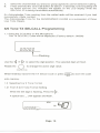
1
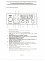
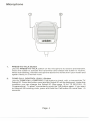
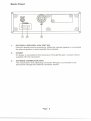
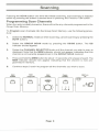
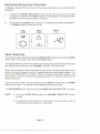
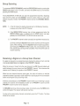
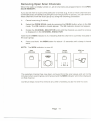
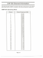
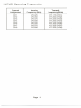
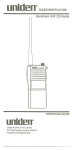
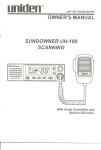
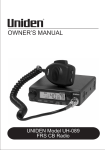
unidE!n$
UHF CB TRANSCEIVER
OWNER'S MANUAL
SUNDOWNER UH-O99
SCANNING
unldm
UH-099
SCAN
11
D D
0 0
Sun downer
gQ
~~
-
OSlGS
ID
CAL MEMCUP1SQ
SRF
os
" ""1
""a"DD_",
L,l L,l
r"""'j",,
GS
SCN
00
~ o~
With Built-in SELCALL
Contents
Controls/lndicators/Connections
FrontPanelControls
FrontPanelIndicators
"
Microphone
"
Back Panel
...
Getting Started
"...5
6
Mobile Station Installation
Choosing an Antenna
Ground System
6
6
6
Operation
7
Howto Receive
"
7
,
How to Transmit
7
Scanning
8
Programming Scan Channels
Removing Group Scan Channels
Open Scanning
Group Scanning
Receiving a Signal on a Group Scan Channel
Removing Open Scan Channels
Reinstalling Channels into the Scan Group
8
9
9
10
10
11
12
Selective Calling
13
Outline
ReceiverQuieting
"
13
14
."
Call Receiving
Tone Squelch Scanning.
Tone Calling
5/6 Tone TX SELCALL Programming
Group Calling
14
14
15
16
17
"
5/6 Tone SELCALL Programming
Receiver SELCALL ID
Tone Period
Lead-in Delay
Lead-in Tone
Alarm Mode
19
...
"
"
...,
"
,
Care and Maintenance
Notice
Preventive Maintenance
Troubleshooting ."
Memory Backup
20
22
24
25
27
29
...
,..
"
,.
,
..,.
UHF Channel Information
Specifications.
Warranty
2
2
3
4
29
29
...29
29
30
......
... ...
Page 1
32
35
Contro 15/1nd icators/Con nactio ns
Front Panel Controls
unldl!l1
UH-099
@
@
SCAN
OSIGS
DD
MEM
,-,,.,,j ,-,,-,,-,
000.000
11Hz PII
GS
SCN
D'
L..ENT-'
Oo~
oLJ
L '
L..~-'
CD
1.
2.
3.
4.
5.
6.
7.
G)
@
@
-- --
ID
CALMEMCUPTSQ "
SRF
os
rJ)
@
@
"
l 1l 1
~
@)
CHANNEL SELECTOR
Selects the desired channel for transmission and reception.
SCAN CONTROL (SCAN)
Scans channels programmed in the selected SCAN mode.
NOTE: The radio will not scan if the selected Scan Memory has not been
programmed.
OPEN SCAN/GROUP SCAN CONTROL (OS/GS)
Selects the desired SCAN mode. Press the button once to toggle between
OPEN SCAN and GROUP SCAN modes.
TONESQUELCH CONTROL (T.SQ)
Turns on or off the T.Sa channel memory when the button is pressed for 1.5
seconds. (Any channel can be set.)
BACKLIGHT CONTROL H).i
Changes the backlight intensity to BRIGHT, MEDIUM or OFF when the
button is momentarily pressed. Changes the backlight color to either green or
amber when the -:Q-button is pressed for 1.5 seconds.
DUPLEX CONTROL
Programs semi-duplex operations for channels 1 through 8.
MEMORY CONTROL (MEM)
Places channel numbers into the memory scan list (OS or GS), when pressed
for 1.5 seconds while in the NORMAL mode, and removes channel numbers
from the memory list when pressed again for 1.5 seconds.
Page 2
@
8.
SQUELCH
CONTROL
Eliminates received background noise in the absence of an incoming signal.
Turn the control knob fully counter-clockwise and then slowly rotate clockwise
until the received noise is eliminated.
9.
VOLUMECONTROL
10.
Turns the radio on and increases the volume level when turned clockwise.
Decreases the volume level and turns the radio off when turned counterclockwise.
MICROPHONE SOCKET
11.
The microphone plug is inserted into this socket.
LIQUID CRYSTAL DISPLAY (LCD)
Uses several indicators to show the current operational mode. The two digits at
the right indicate the selected channel. The smaller two and three letter displays
indicate which feature is currently active.
FRONT PANEL INDICATORS
IJ3I
SRF
CAL MEM DUP TSQ
...11111
'f 'f 'f 'f'f 'f
0 0 O. 0 0 0 MHz
OS
GS
PAl SCN
TX INDICATOR (TX)
The "TX" and "RF" icons appear during transmission.
CAL INDICATOR (CAL)
The "CAL" icon appears when an incoming tone code successfully opened the
Tone Squelch, or when TX SELCALL codes are being transmitted.
MEMORY INDICATOR (MEM)
In the normal mode (Scan Mode Off) the "M EM" icon appears when the channel
indicated by the CHANNEL INDICATOR is programmed in the selected
scan memory.
DUPLEX INDICATOR (DUP)
The "DUP" icon appears when the Duplex Channel Operation is selected.
SIGNAL/RF LEVEL INDICATOR
Indicates the relative signal strength level (S) when receiving, or the relative TX
power (RF) level when transmitting.
TONE SQUELCH INDICATOR (TSQ)
The "TSO" icon appears when the Tone Squelch has been activated.
OPEN SCAN INDICATOR (OS)
The "OS" icon appears when the Open Scan Mode is selected.
GROUP SCAN INDICATOR (GS)
The "GS" icon appears when the Group Scan Mode is selected.
SCAN INDICATOR (SCAN)
The "SCN" icon appears when Scan is activated.
PRIORITY INDICATOR (PRI)
The "PRI" icon appears only when in the GS Mode and Scanning, either when
the PRI channel becomes active or when the channel knob is rotated to select
a new PRI channel.
Page 3
Microphone
1
1.
2
PRESS- TO-TALK Button
Use the PRESS- TO-TALK button on the microphone to receive and transmit.
Press the button to activate the transmitter and release the button to receive.
When transmitting, hold the microphone about two inches from your mouth and
speak clearly in a normal voice.
2.
TONE CALL CONTROL (CALL) Button
Use the TONE CALL CONTROL (Call) button to check, edit, or transmit the TX
Selcalll D. Press the button once and the Selcalll D will be displayed. Under this
condition you can change the Selcall ID (See page 16 for TX SELCALL ID
Programming). To abort, momentarily press the Call button again. If you want
to transmit the existing code, press and hold the Call button for more than 1.5
seconds.
Page 4
Back Panel
...
IIXI'
~
(8)
3
1.
EXTERNAL SPEAKER JACK (EXT.SP)
Used for remote receiver monitoring. When the external speaker is connected
the internal speaker is automatically disconnected.
2.
POWER
DC power is connected to the transceiver through this jack. A power cord is
supplied with the transceiver.
3.
ANTENNA CONNECTOR (ANT)
The transmission line cable plug connector (M-type) is connected to the
transceiver through this antenna connector socket.
Page 5
Getting Started
Mobile Station Installation
Select the location of the transceiver and microphone bracket before starting the
installation. The location should be convenient and should not interfere with the driver
or passenger in the vehicle. The transceiver should be securely fastened to a solid
face, using the mounting bracket and self-tapping screws which are provided.
Choosing an Antenna
Since the maximum allowable power output of the transmitter is limited by the
Spectrum Management Agency (SMA), the antenna is a very important factor for
transmission distance. For this reason, the installation of a quality antenna is strongly
recommended. The SundownerUH-O99
is a superior transceiver, however, installing
an inferior antenna may cause a reduction in performance.
Only a properly matched antenna system will allow maximum power transfer from the
50-ohm transmission line to the radiating element. Your Uniden dealer is qualified to
assist you in the selection of a compatible antenna to meet your application
requirements.
For automobile installation, the whip antenna is recommended. The most efficient and
practical installation is a full quarter wave whip antenna mounted on the rear deck
midway between the rear window and bumper.
A short "loaded" whip antenna is easier to install on an automobile.
as efficient as a full quarter wave whip antenna.
However it is not
For marine installation, consult your dealer for information regarding an adequate
grounding system and prevention of electrolysis between fittings in the hull and the
water.
Ground System
Connect the red DC power cord from the transceiver to the positive (+) battery terminal
or another convenient point and connect the black power lead to the vehicle frame,
or the negative (-) battery terminal.
Page 6
Operation
How to Receive
1.
Confirm that the power source, antenna, and microphone are connected
properly before proceeding to the following steps.
2.
Turn the unit ON by rotating the VOLUME control clockwise.
3.
Set the CHANNEL CONTROL knob to the desired channel.
4.
Set the VOLUME control to a comfortable
5.
listening level.
Listen to the background noise from the speaker. Turn the SQUELCH control
slowly clockwise just until the noise is eliminated (no signal should be present).
Leave the control at this setting. The Squelch is now properly adjusted. The
receiver will remain quiet until a signal is actually received. Do not advance the
control too far, or some of the weaker signals will not be heard.
How to Transmit
1.
Carefully read the SMA Rules and Regulations prior to operating the transmitter.
2.
Select the desired channel.
3.
To transmit, press the PRESS- TO-TALK button on the microphone. Hold the
microphone 2-4 inches from your mouth and slightly to one side so that your
voice does not project directly into the microphone (this provides the best
results). Speak at a normal level. Never raise your voice or shout into the
microphone. Whenever the PRESS- TO-TALK button is pressed, the TX indicator will light.
~
ill
WARNING
The Transceiver Voltage Standing Wave Ratio (V.S.WR.)
measurement must be performed prior to the use of the
transmitter. A V.S.WR. ratio in excess of2:1 may damage the
transmitter.
Page 7
Scanning
Pressing the SCAN button one time will initiate scanning, and scanning is stopped
either by pressing the button a second time or pressing the Press-to- Talk button.
Programming Scan Channels
When the radio is initially turned on, there will not be any channels programmed in the
Group Scan Memory.
To Program
dure:
1.
2.
3.
4.
5.
scan channels into the Group Scan Memory, use the following proce-
Select the NORMAL
SCAN button.)
mode (or when scanning, cancel scanning by pressing the
Select the GROUP SCAN mode by pressing the OS/GS button. The GS
indicator should appear.
Rotate the CHANNEL SELECTOR knob until the channel you wish to scan is
displayed. Note that the MEM indicator should not appear, indicating that this
channel is not currently programmed in the GROUP SCAN memory.
Press and hold the MEM button for about 1.5 seconds until a beep is heard. The
MEM indicator should now appear indicating that the channel is now programmed in memory.
Continue steps 3 and 4 to program all the channels you wish to scan.
Select
Group
SCAN
Select
NORMAL
SCAN
Select
CHANNEL
IdII!n
OSIGS
D
D
1+1
Program
CHANNEL
Mal
'MEM'lcon
...u,.
"Ef(11\
ON
D
1+
1+
(0)
Page 8
I) I
.... BEEP!'"
U',
GS
,'-'
Removing Group Scan Channels
To Delete a programmed channel from the Group Scan Memory, use the following
procedure:
1.
2.
Rotate the CHANNEL SELECTOR knob until the channel you wish to remove
is displayed. Note that the MEM indicator should appear, indicating that this
channel is currently programmed in memory.
Press and hold the MEM button for about 1.5 seconds until a beep is heard twice.
The MEM indicator should now be off.
Remove
CHANNEL
Select
CHANNEL
I81Iden
MEM
+
(0)
'MEM'
Icon
OFF
D
UII
GS
1)) t
.-. BEEPI'"
,Ll
Open Scanning
To commence open scanning, select the OPEN SCAN mode by pressing the OSlGS
button when in GS mode. Then press the SCAN button.
The SUNDOWNER UH-099 will commence scanning the programmed channels, and
will indicate each channel on the CHANNEL indicator as it is scanned.
When a busy channel is found, the radio will 'lock' onto it, and will remain there for as
long as the signal is present, and for 3 seconds after the transmission ceases. This
allows the SUNDOWNER UH-099 to hold the channel during short breaks in the
conversation. Once the channel has remained clear for 3 seconds, the radio will
resume scanning.
If you do not wish to listen to a busy channel, you can SKIP over it by pressing the MEM
button on the radio. The receiver will immediately resume scanning.
The SCAN MODE will be cleared when the PRESS- TO-TALK
NOTE:
BUTTON is pressed.
1. During the OPEN SCAN mode, the CHANNEL SELECTOR knob is
ignored.
2. The scan rate in this mode is 0.1 second per channel. In other words, all
40 channels can be scanned in 4 seconds.
Page 9
Group Scanning
TocommenceGROUP SCANNING, select the GROUP SCAN mode by pressing the
OS/GS button when in the OS mode, and select the SCAN mode by momentarily
pressing the SCAN button.
The SUNDOWNER UH-O99 will now scan the programmed channels, displaying
each channel number and the PRIORITY channel number. Before it scans each
channel, it quickly "checks" the PRIORITY channel (set by the CHANNEL SELECTOR).
NOTE:
1. In the GS mode, the starting channel prior to GS Memory Scanning
is always set as the Initial PRI Channel.
2. If the GROUP SCAN memory has not been programmed when the
GROUP SCAN mode is selected and the SCAN button has been
pressed, the SUNDOWN ER UH-O99will emit an error tone.
3. The PRIORITY channel number can easily be read when necessary by:
(a) Simply turning the Squelch knob counter-clockwise until the squelch
opens. After checking, return the Squelch knob to the previous position.
(b) Pressing the PRESS- TO-TALK button, the unit will transmit on the
PRI channel and scanning will be cancelled. Press the SCAN button to
resume scanning.
Receiving
a Signal on a Group Scan Channel
If a signal is received on a programmed scan channel, the radio will 'lock' onto that
channel provided there is no signal on the PRIORITYchannel.
When the receiver is 'locked' onto the scan channel, the LCD Channel Indicator will
switch between the scan channel and the PRIORITY channel. This is because the
receiver is still 'listening' for signals on the PRIORITY channel.
When the scan channel becomes quiet again, the radio will continue to hold the
channel for another 3 seconds in order to allow for a natural pause inthe conversation
before resuming the Group Scanning mode.
If there is a transmission on the PRIORITY channel while you are listening to a scan
channel, the receiver will immediately transfer to the PRIORITY channel and the
PRIORITY channel number will be displayed.
To RESUME scanning, while receiving a signal, momentarily
on the front panel. The receiver will resume scanning.
press the MEM button
To stay on the current active channel, momentarily press the PTT button. The Scan
Mode will be cleared.
Page 10
Removing Open Scan Channels
When the radio is initially turned on, all 40 channels are programmed in the OPEN
SCAN MEMORY.
If you do not wish to scan some particular channels (e.g. if one or more channels are
continually busy and always causing the scanning function to pause), you can remove
these channels from the scan group by using the following procedure:
1.
2.
3.
Cancel scal)ning (if active).
Select the OPEN SCAN mode by pressing the OS/GS button when in the GS
mode. The OS indicator should appear. The GS indicator should not appear.
Rotate the CHANNEL SELECTOR knob until the channel you wish to remove
is displayed on the CHANNEL INDICATOR.
Note that the MEM indicator is lit, indicating that this channel is currently included in
the scan group.
4.
Press and hold the MEM button for about 1.5 seconds until a beep is heard
twice.
MEM indicator IS
. now off.
NOTE: The
Select
'MEM'Icon
OFF
Remove
CHANNEL
Select
CHANNEL
MEM
lLJ
1 )) I
1=1 OS
LID
.... BEEPI'"
The selected channel has now been removed from the scan group and will not be
included when scanning has commenced and the MEM indicator will not be displayed
on that channel.
Continue steps 3 and 4 to remove any other channels you do not wish to scan.
Page
11
Reinstalling Channels into the Scan Group
To reinstall previously deleted channels into the scan group, simply repeat steps 3 and
4. However, this time note that a beep will be heard when the MEM button is pressed,
and the MEM indicator will light, indicating that the selected channel is now included
in the scan group.
Select
CHANNEL
I81kII!n
Reinstall
CHANNEL
MEM
lJH.O99
,I,
,..
~E~-
'MEM'
Icon
ON
11'
os
(0)
1) t
U"
"-'
BEEPI'"
When finished, rotate the CHANNEL SELECTOR dial and notice that the MEM icon
is indicating which channels are programmed and which have been removed.
Page 12
Selective Calling
Outline
Selective Calling (SELCALL) is a special Sequential Tone Squelch System that
allows the user to receive/transmit calls selectively from/to an individual or a group,
on a shared busy channel.
The SUNDOWNER UH-O99 has a specially built-in Selective Calling (SELCALL)
system. Exceptional features like Receiver Quieting, Tone Squelch Scanning, Tone
and Group Calling make the SUNDOWNER UH-O99superior to any transceivers in
its class.
Receiver Quieting (Tone Squelch)
When activated, automatically mutes the receiver audio circuit of the radio. It will stay
in this "Quief' mode as long as the SELCALL tone code (SELCALL ID) required to
open the muting circuit is not received.
Call Alarm
When a received code matches to your SelcalllD,
you that a caller is on the channel.
Tone Squelch Scanning
Scans only Tone Squelched
Channels.
Tone Calling
Allows you to selectively
call other radios.
Group Calling Capability
Transmits and Responds to Group Calls.
Page 13
an alarm will be emitted informing
Receiver Quieting
Puts the receiver in the "Ouiet" mode (also known as the "Tone Squelch"
mode). When activated, the transceiver prevents any unwanted conversations
in the channel from being heard unless the call is specifically directed to you
and the SELCALL ID required to open the "Ouiet" condition has been received.
To activate:
1.
Select the channel you want to put in Quiet mode using the Channel Selector
knob.
2.
Press the T.SO button for about 1.5 seconds. One beep is heard and the T.Sa
indicator appears on the LCD display. Under this condition, the PRESS- TOTALK button is temporarily disabled. If you wish to use the same channel for
normal communication simply remove the channel from Quiet mode.
Note: Channels that are stored in either OS or GS (MEM), when put in the Quiet
condition, will be skipped during OS/GS Memory Scanning
If GS Scanning is used and the starting channel is a T.SO Channel, the PRI
Channel will not be set. Rotate the channel knob to set a new PRI channel.
To deactivate the Quiet Condition:
1.
2.
Manually select the Tone Squelched
Channel.
Press the T.Sa button for about 1.5 seconds. Two beeps are heard and the
T.SO indicator disappears from the LCD display.
Call Receiving
While in the T.SO condition, when UH-099 receives a code matching your
SELCALL ID, it will perform the following operations:
1.
Automatically
2.
Informs you that a caller is on the channel by emitting a CALL ALARM (Default
Alarm Setting: four successive beeps in a regular interval for 10 seconds. Refer
to "Programming
Method" for other alarm settings) and displays the CAL
indicator.
3.
Flashes the T.SO indicator for about 20 seconds allowing you to use the
PRESS-TO-TALK button. Ifyou are not be ableto respondwithin the 20 second
period, T.SO stops flashing and Quiet mode resumes.
responds to the caller by transmitting
Acknowledge
Tones.
Tone Squelch Scanning
If you are using two or more channels in the T.SO mode, you can monitor all
of these channels for selective calls by using the T.SO Scanning feature.
To use this feature:
Page 14
Start the T.Sa Scan by pressing the T.Sa button during Open Scan or Group
Scan.
Unlike Normal Scanning, T.Sa Scanning checks the detected carrier for
SELCALL information. If this information is not found, T.Sa scanning resumes.
When a call is received during T.Sa Scanning, UH-099 follows the same
response as when receiving a call on a Tone Squelch Channel. It differs only
in the following ways.
1.
If the call is not answered within the 20 second period, T .sa Scanning resumes.
The CAL indicator remains on the LCD.
To look for the channel where CALL is received:
a. Cancel T .sa Scanning by pressing the Scan button.
b. Using the Rotary button, browse through the T.Sa Channels.
The CAL indicator marks the channel where the call is received.
2.
When answered, T.Sa scanning is automatically
removed from the auiet Operating mode.
deactivated.
The channel is
To deactivate T.Sa Scanning:
1.
Press the T.Sa button. The unit returns to the Normal Scanning Mode, or
2.
Press the Scan button. The whole scanning operation is cleared.
3.
When a SELCALL is received, press the PRESS-TO-TALK
button.
Note: The chance of receiving and decoding SELCALLs effectively during T.Sa
Scanning can be increased in manydifferent ways. You can either decrease
the number of channels to be scanned thus increasing the scanning speed,
or change some of the SELCALL parameters (refer to "Other SELCALL
Parameters" on page 21).
Be sure that each member of your group uses the same configuration,
otherwise, the chance of selectively calling each other will be
decreased.
Tone Calling
Tone Calling allows you to selectively call other radios.
To do this, the SELCALL ID of the radio you are going to call should be in the
Transmitter's SELCALL ID memory (refer to "5/6 Tone TX SELCALL
Programming" on page 16).
To Call:
Page 15
1.
2.
Select the
Press and
be heard
SELCALL
channel that you and your group agreed to use for Selective Calling.
hold the Tone Call Button for about 1.5 seconds. One long beep will
and the CAL indicator will appear on the LCD display while the
ID is being transmitted automatically.
An Acknowledge Tone coming from the called radio will be received if you had
successfully made contact.
The Acknowledge Tone for the SUNDOWNER UH-099 is a succession of three
Low Tone Beeps.
5/6 Tone TX SELCALL Programming
1.1 Press the TC Button on the Microphone.
The TX SELCALL Code will be displayed. (Factory default:
00000)
"""""
L-fL-fL-fL-fU
LFlaShing
Use the <] or t> to select the digit position. The selected digit will flash.
Rotate the
0
to change the active digit value.
Channel Knob
When finished, transmit the TX Selcall Code or press
I ENT Ito store
MEM
onto memory.
1.2 Selecting 5 or 6 Tone Format
1.21 From 5 to 6 Tone Format Setting
While the 5th digit is flashing,
A space bar [-]
Press the t> .
will appear and flash.
MEM
,; n ,; ,; ,-..\ I I.~'LL~!b~!.!..=.. /1\
1-'
os ~ l- I
Page16
the code
Assign a SELCALL number on this position. Follow procedure 1.1 for further
TX SELCALL ID editing. When finished, press
I ENT I or transmit
MEM
the code
to save the new setting onto memory.
1.22
From 6 to 5 Tone Format Setting
Select the 6th digit position, change the setting from the assigned SELCALL
number to a space bar [-].
Example
MEM
L1
S
1:"1-.
_,11
le-tUC"i"""
..J '-"".0.,-
os
11
l I
-
To
MEM
'~-IY,
'1..
-
S
c"
LA
,1/
-~
os
...-
,-
-
11
l I
Follow procedure 1.1 for further TX SELCALL editing. When finished, press
I ENT Ior transmit
MEM
the code to save the new setting onto memory.
Group Calling
The SUNDOWNER UH-O99 has the capability to respond to Group Calling and
to transmit Group Calling Codes.
Group Calling allows you to call members of your group simultaneously.
However, to do this, you need to follow a certain format when programming
your TX SELCALL ID.
Page 17
TX SELCALL ID Format
To call
Transmitter SELCALL ID
10 radios
100 radios
1000 radios
10000 radios
[xl
[xl
[xl
[xl
[xl
[xl
[xl
[AJ
[xl
[xl
[AJ
[AJ
[xl
[AJ
[AJ
[AJ
[AJ
[AJ
[AJ
[AJ
where: [xl is a common SELCALL ID prefix of your group and,
[AJ is the CCIR Assigned Group Tone Code
example:
If one group comprises
10 members with SELCALL
IDs.
ranging from
[1 J [2J [3J [4J [0],
[1J [2J [3J [4J [1],
[1 J [2J [3J [4J [2],
[1 J [2J [3J [4J [3J,
to
[1J [2J [3] [4J [9],
All in T.SQ mode at CH20.
If someone transmits [1J [2J [3J [4J [AJ on CH20, all of the above units will open
their Tone Squelched Receiver.
Group Calls and ordinary SELCALLs can be differentiated in the following
manner.
Group Call Ordinary Selcall
Note:
Low tone beeps
tone beeps
- High
Acknowledge tones will not be received when a Group Call code is transmitted. If all radios respond, acknowledge tones would only "litter" the channel
with crisscrossing signals.
To use the Group CalJing Feature effectively, your RX SELCALL ID should be
well arranged and assigned.
Page 18
5/6 TONE SELCALL PROGRAMMING
Since UH-O99 can support either a 5 or 6 tone signalling format, you and your
group must decide which format to use. The following is a basic outline of
SELCALL Programming.
Press and Hold
I I on Power
TSQ
ON
RECEIVER CODE
PROGRAMMING
Press
ITSQ I
Press
I I
Press
I I
TSQ
TONE PERIOD
PROGRAMMING
Press
I I
TSQ
ALARM MODE
PROGRAMMING
Press
LEAD-IN DELAY
PROGRAMMING
I I
TSQ
To select, press
LEAD-IN TONE
PROGRAMMING
I MEM
I
ENT
To save new a setting after programming,
press
To deselect, momentarily, press ITSQI
The unit goes to the next programmable
I I
I MEM
I
ENT
parameter.
To exit, press and hold TSQ for more than 1 .5seconds.
The unit goes to Normal Operating mode.
Page
19
TSQ
Receiver SELCALL ID
To program your own receiver SELCALL ID, perform the following procedure.
I
Press and Hold
TSQ
I, then
turn on the Power.
1.1 Initial Display and Status (factory default: 00000)
RX SELCALL Code Programming
TSQ
,~
"~
~
,-, It ,-, ,-, ,-,
UUUUf-t
1.2 When the
I ENT Ikey
MEM
I
is pressed while in this condition, the last digit will begin
to flash and RX Tone Editing is possible.
I
TSQ
,~
"~
~
,-, ,-, ,-, ,-, ,-,
f-tf-tf-tf-tU
LFlaShing
Use the <J or [> to select the digit position. The selected digit will flash.
Rotate the
0
to change the active digit value.
Channel Knob
When finished, press
The programmed
Press
Or
press
ITSQ
MEM
the RX Code into memory.
code flashes and three successive
I Ifor about
TSQ
I ENT I to store
beeps are heard.
1.5 seconds to exit. The radio returns to normal operation.
I momentarily
to go to the next programmable
parameter.
1.3 Selecting 5 or 6 Tone Format
1.31 From 5 to 6 Tone Format Setting
While the 5th digit is flashing, press
[>.
A space bar [ -]
flash.
Page 20
will appear and
I
TSQ
,-"
~
~
" " " " ,~\I1
"
- -
Uf-If-IUY
11\
Assign a SELCALL number on this position. Follow procedure 1.2 for further
RX SELCALL ID editing. When finished, press
I ENTI to save
MEM
the new
setting.
1.32 From 6 to 5 Tone Format Setting
Select the 6th digit position, change its setting from the assigned SELCALL
number to a space bar [-].
Example
TSQ
l--
\Lt
I 1 1 U ,-., '"
IC:J , ",CI,"
II'
I
D
To
I
TSQ
I1
l---
IU,-\II
IC:J ,' -"11\
l'
r..-
Follow procedure 1.2 for further RX SELCALL IDediting. When finished press
I MEM
Ito save
ENT
the new setting.
Other SELCALL Parameters
Aside from the Transmitter and Receiver lDs, you should also be familiar with some
of the other SELCALL Parameters. This section outlines the following programming
modes.
- Tune Period
- Lead-in Delay
- Lead-in Tone
- Alarm
RX SelcalllD, Tone Period, Lead-in Delay, Lead-in Tone, and Alarm Programming
are mentioned separately from the TX SELCALL Programming because they are not
frequently changed. Special procedures have been designed to prevent accidental
programming.
Page 21
Tone Period
Tone Period is the duration of one tone in a SELCALL ID sequence. The setting of this
parameter depends on the type of application. On long distance communications for
example, where the signal strength of the transmitted information is greatly reduced
and affected by noise, it is advisable to use a longer Tone Period. A long Tone Period
gives the decoder more time and information to check and evaluate the code.
However, be sure that all radios in your group use the same tone period setting.
Otherwise you will not be able to selectively call one another.
The Sundowner UH-099 allows you to select which tone period is best for you. The
four most commonly used tone settings (20, 40, 70, or 100 mSec) are available. With
the freedom to change this parameter, you can easily adapt to the existing system in
your group without the inconvenience of having the unit serviced by the dealer.
2.1 From the Initial Display Status (1.1), press
appear.
I Iand the following
TSQ
mode will
Tone Period Programming
TSQ
" ,-,
u '-Iu
2.2 Next press
I ENT I and
MEM
"
,-- "--
I
O'-fO (factory default setting) will flash and Tone Period
Editing is possible.
TSQ
",-,,-,
U
'L'
l
"--
,
Flashing
Page 22
~
I
l-- 1
Rotate the
0
to change the Tone Period value.
Channel Knob
[
[
100
1SQ
TSQ
020
When finished, press
[
,Odj
c:
I ENT Ito store
ME M
"
..71
,- I..lJ
040
-PdJ
TS4PdJ
onto memory. The displayed Tone Period
stops flashing and three successive beeps will be heard. PreSSITSQI for about 1.5
seconds to exit. The radio returns to normal operation. Or press
momentarily
to go to the next programmable
parameter.
Page 23
I I
TSQ
Lead-in Delay
Lead-in Delay is a SELCALL transmission parameter that "wakes-up" and helps the
receiver of the other radio to lock onto the incoming signal. Each time a SELCALL ID
is transmitted, the Lead-in Delay attaches itself to the beginning of the code sequence
and cause the transmitter to be on for a longer period prior to the code transmission.
This makes for a stronger communication link between the transmitter and the other
receiver.
One major advantage to having the longer Lead-in Delay is when selectively calling
another radio via a repeater station. A long Lead-in Delay helps to stabilize both the
communication link from your radio to the repeater station and from the repeater
station to the other radio.
3.1 Lead-in Delay Programming
I I
From the Tone Period Programming Status (2.1), press the Tsa button and the
following mode appears.
Lead-in Delay Programming
"ISO'
,- ,-,,-,
='~I~'
--'
L I_I
Note: 500 mSec is the factory default setting of UH-099 for Lead-in Delay.
3.2 Next press
Use the
0
Channel
I MEM
ENT I and Lead-in
Delay Editing is possible.
to change the Lead-in Delay value.
Knob
1SQ
SDD
/[ 1SQ
'-IDDD
I
L Ll
I
L
I
dJ\
,nnn
'uuu
\
1SQ
I _,
L Ll
/-
1SQ
nnn
3 uuu
I
I
L Ll
500,1000,2000,3000,4000
Page 24
mSec
When finished,
pressl MEMIto store onto memory. The displayed Lead-in Delay
ENT
stops flashing and three successive
beeps will be heard. pressl TSQI for about 1.5
seconds to exit. The radio returns to normal operation. Or press
to go to the next programmable
I Imomentarily
TSQ
parameter.
Lead-in Tone
The Lead-in Tone, when programmed, "rides" on the Lead-in Delay. Hence, when
transmitting a SELCALL ID, a continuous tone will be heard for the duration of the
Lead-in Delay.
The main purpose of the Lead-in Tone is to increase the probability of contact between
your unit and another radio when TSQ Scanning.
Normally during TSQ Scanning, if a carrier is detected and the unit does not notice
SELCALL information on its first "glance" of the particular signal, scanning resumes.
But if a Lead-in Tone is present, the unit continues
received.
4.1 From the Lead-in Delay Status (3.1), press
appears.
to wait until the SELCALL
I
TOO
,- ,- ,,
,O'rC
TSQ
Iand the following
mode
I ,~
LI
Note: Tone _1 is the factory default setting of the UH-O99 for Lead-in Tone.
4.2 Next press
I ENT Iand
MEM
,-
,onc
,-
Lead-in Tone Editing is possible.
I,
L-
Usethe
0
TOO
I ,~
LI
Flashing
to change the Lead-in Tone value.
Channel Knob
Page 25
ID is
T$O
~one_1
T$O
~.n.
T$O
Gone_F
..
..
1 11
T$O
L ,~
-
GJ1I\e_o
T$O
[TOnem2
1 TI
Ll
T$O
1 11
..
..
LI~
[TO80m3
1 11
L ,~
T$O
1 'J
LI
[Tone A
[ToneB
T$O
T$O
T$O
LI
1 1-1
LI
1 I-]
LI
1 I-]
If you want to remove the Lead-in Tone, choose
the Space [-] Bar.
When finished press
flashing
1 11
L ,~
[Tone 9
[Tone C
Note:
1 11
L ,~
and
three
I ENT I to store
MEM
successive
beeps
onto memory. The selected Lead-in Tone stops
will
be
heard.
Press
to exit. The radio returns to normal operation. Or press
I
TSQ
Ifor
about
I Imomentarily
TSQ
1.5
seconds
to go to the
next programmable parameter.
Note: Make sure that all members of your group use the same Lead-in Tone.
Otherwise, you will lessen the probability of receiving and successfully
decoding a SELCALL call while TSQ Scanning
Page 26
Alarm Mode
5.1 From the Lead-in Tone condition
(4.1) press
I Iand the following
mode
TSQ
appears.
5.2 Next press
I ENT I and Alarm
MEM
TOO
(
TSQ
,- ,L-a,-"
"L
Mode Editing is possible.
'~JI,,'-'u' a
L.
"
"
I
"
TSQ
't , , ,'tU' Q
I
L-
"
"
Flashing
I
L..
TOO
I
I , L-
AUra
J
"~
Call Alarm Continue Mode
t
Flashing
Use the
0
Call
Alam>
A"'<><>II
Mode
to change the Alarm Mode.
Channel Knob
When finished, press the
I ENT Ito store
MEM
onto memory. The selected Alarm mode
stops flashing and three successive beeps will be heard. Press
I Ifor about 1.5
TSQ
seconds to exit. The radio returns to normal operation.
When a received
Call Alarm
code matches to your
Receiver SELCALL IDand you selected the:
Auto Mode
1. The unit will transmit an Acknowledge Tone to the Caller.
2. Emits CALL Alarm for 10 seconds only.
3. Resumes Quiet condition automatically after 20 seconds if the call is not answered.
4. The unit will start decoding again when the 20 second period elapsed and the call
remained unanswered.
Page 27
Call Alarm Continue
Mode
1. The unit will transmit an Acknowledge Tone to the Caller.
2. Initially emits an alarm of four successive beeps for 20 seconds and then two
successive beeps every four seconds continuously unless answered.
3. Never resumes the Quiet Condition.
4. Continues to check if incoming codes have your Receiver SelcalllD even though
the Quiet Condition is already opened. When detected, it will send an Acknowledge
Tone to the caller and then resets the Call Alarm.
.
: For both of the above mentioned modes, transmission
by using the Press-to- Talk
button is possible when the "TSQ" icon is flashing.
Default Setting (Factory Default)
A. RX SELCALL ID:
B. TX SELCALL ID:
C. Tone Period:
D. Lead-in Delay:
E. Lead-in Tone:
F. Alarm:
00000
00000
40msec
500msec
Tone "1"
Auto
IMPORTANT
Be sure that the Tone Format (5 Tone or 6 Tone), Tone Period Setting and the
Lead-in Tone for all of the radios in your group are all the same. Otherwise you
will not be able to selectively callone anothereffectively.
Page 28
Care and Maintenance
Notice
If the UH-099 has been subjected to extreme high .temperature (above 60°C) for a
prolonged period of time, blackening of the Liquid Crystal Display (LCD) may occur.
This is not a fault. Normal LCD operation resumes when the temperature stabilises
back to proper operating conditions (0 to 55°C).
Preventive Maintenance
The following system checks should be made every six to twelve months:
1.
Check the Standing Wave Ratio (SWR).
2.
Inspect the tightness of all electrical connections.
3.
Inspect the antenna coaxial cable for wear or breaks on the shielding.
4.
Inspect the tightness of all screws and other mounting hardware.
Troubleshooting
Should the unit malfunction or perform poorly, follow the procedures indicated below:
1.
If the transceiver is completely inoperative
* Check the power cord and fuse.
2.
If there is trouble with receiving ...
* Check the VOLUME control setting.
* Be sure the SQUELCH is adjusted properly. Possibly the radio is oversquelched.
* Check that the radio is in an operational mode.
3.
If there is trouble with transmitting ...
* Check that the transmission line (coaxial cable) is securely connected to the
ANTENNA connector.
*
*
...
Check that the antenna is fully extended for proper operation.
Check that all transmission line (coaxial cable) connections are secure and
free of corrosion.
Memory Backup
A built-in capacitor protects the channels stored in the SUNDOWNER UH-099
memory for up to 2 weeks after the DC power cable is disconnected.
Page 29
UHF CB Channel Information
This radio has been designed to provide a high level of performance in the Citizens
Band Radio Service, which is comprised of the following frequency assignments:
SIMPLEX Operating Mode
Channel
Channel Frequency in MHz
1
2
3
4
5
6
7
8
9
10
11
12
13
14
15
16
17
18
19
20
21
22
23
24
25
26
27
28
29
30
31
32
33
34
35
36
37
38
39
40
476.425
476.450
476.475
476.500
476.525
476.550
476.575
476.600
476.625
476.650
476.675
476.700
476.725
476.750
476.775
476.800
476.825
476.850
476.875
476.900
476.925
476.950
476.975
477.000
477.025
477.050
477.075
477.100
477.125
477.150
477.175
477.200
477.225
477.250
477.275
477.300
477.325
477.350
477.375
477.400
Page 30
DUPLEX Operating Frequencies
Channel
Assignment
CH1
CH2
CH3
CH4
CH5
CH6
CH7
CH8
Receive
Frequency (MHz)
Transmit
Frequency (MHz)
476.425
476.450
476.475
476.500
476.525
476.550
476.575
476.600
477.175 (CH31)
477.200 (CH32)
477.225 (CH33)
477.250 (CH34)
477.275 (CH35)
477.300 (CH36)
477.325 (CH37)
477.350 (CH38)
Page 31
Specifications
General
Channels
Frequency Range
Crystal Oscillator
Microphone
Speaker
Antenna Connector
Jacks & Connectors
Controls
Indicators
Cabinet Size
Weight
Operating Temperature
Power Requirements
SMA Approval
Accessories
: 40
: 476.425MHzto 477.40MHz
:3
: 600 ohm, Dynamic Type
: 8 ohm, 3W
: M-Type
: Mic4P Metal
EXT SP 3.50
DC Power 3P Type
: PRESS-TO-TALK Button (Microphone)
TONE CALL Button (Microphone)
SCAN/SEEK Button
OPEN SCAN/GROUP Button
BACK LIGHT CONTROL Button
OFFNOLUME Control
SQUELCH Control
DUPLEX Button
TONE SQUELCH Button
CHANNEL SELECTOR Knob
: DUPLEX Indicator
TX Indicator
CALL Indicator
TSQ Indicator
GROUP SCAN Indicator
MEMORY Indicator
OPEN SCAN Indicator
CHANNEL Indicator
PRllndicator
S/RF Level Indicator
SCAN Indicator
TX/RX FREQUENCY, 5/6 Digit SELCALL ID Indicator
: W: 154.5 mm
H: 52.5 mm
0: 173 mm
: 1.2 kg
: 0° to +55°C
: 13.8 VDC Nominal
: Type accepted under SMAS250
: DC power cable with built-in-fuse, microphone, microphone hanger mounting bracket screw (2), washer (2)
for microphone hanger screw (2),washer (2)for mounting bracket
Page 32
Measurement Conditions
Power Source
Antenna Impedance
Test Temperature
Modulation Frequency:
Mean Signal Input Level:
Reference Audio Output
Power
Reference Modulation
Deviation
Audio Output Load
: 13.8V (DC)
: 50 ohm
: 25°C
1 kHz (RXITX)
1000 ~V
: 500mW
: 1:3 kHz deviation
: 8 ohms resistive
Transmitter Section
Frequency Tolerance at 25°C
(5 minutes after
turning on)
: 1:0.5kHz
Carrier Power
: 5W (max)
Spurious Emission
: -30dBm
Current Drain
: 1700mA
Modulation Frequency Response (1 kHz, 0 dB reference, at 1kHz deviation)
Lower at 500 Hz
: -6 dB
Upper at 2.0 kHz
: +6 dB
Microphone Sensitivity
: 1mV
for 3 kHz Deviation
Maximum Deviation
: 1:4.75
at 1 kHz
at 6 kHz
: 1:1.5 kHz (max)
Receiver Section
Sensitivity at 12 dB SINAD: 0.25~V or better
Overall Audio Fidelity
(1 kHz, 0 dB reference)
: +3 dB
Lower at 500 Hz
Upper at 2 kHz
Adjacent Channel
Selectivity (1:25 kHz)
Maximum Audio Output
Power
Audio Output Power at
10% THD
Hum & Noise Ratio at
Input 1mV
Squelch Sensitivity at
Threshold
Squelch Sensitivity at
Tight
Image Rejection Ratio
IF Rejection Ratio
Oscillator Dropout
Voltage
: -6 dB
: 65 dB
: 3W
: 2W
: 40 dB
: 0.1~V
: 1~V
: 60 dB
: 70 dB
: 9V
Page 33
Current Drain at No
Signal
Current Drain at
Maximum Output
: 300mA
: 600mA
SELCALL
Standard
Encode/Decode Format
Transmit Tones
Receive Tones
Tone Periods
Lead-In Delay
Lead-In Tone
: CCIR International
: 5 or 6 Tones
: 0-9, A-D, F
: 0-9
: 20, 40, 70, 100mSec
: 500mSec, 1, 2, 3, 4Sec
: 0-9, A-F
Page 34
Warranty
Uniden Sundowner UH-O99UHF CB Radio
Australian One Year Warranty
Note: Please keep your sales docket as it provides evidence
WARRANTOR:
UNIDEN Australia
ELEMENTSOFWARRANTY:
DURATION:
Pty. Limited ACN 001 865498
UNIDEN warrants tothe original retail owner for the duration of this
warranty, its Sundowner UH-099
Product) to be free from defects
exclusions set out below.
WARRANTY
of warranty.
UHF CB Transceiver Radio (hereinafter referred to as the
in materials and craftsmanship
with only the limitations or
This warranty to the original retail owner only, shall terminate and be
of no further effect ONE (1) Year after the date of original retail sale. This warranty will be deemed
invalid if the product is; (A) Damaged or not maintained as reasonable and necessary,
Modified, altered or used as part of any conversion kits, subassemblies, or any configurations
(B)
not
sold by Uniden, (C) Improperly installed, (D) Repaired by someone other than an authorized
Uniden Repair Agent for a defect or malfunction covered by this warranty, (E) Used in conjunction
with any equipment
or parts or as part of a system not manufactured
by Uniden, (F) Installed,
programmed or serviced by anyone other than an authorized Uniden Repair Agent, or (G) Where
the Serial Number label of the product has been removed or damaged beyond recognition.
PARTS COVERED:
This warranty covers for 1 year, the Sundowner
Unit only. All accessories,
UH-099 UHF CB Transceiver
mounting bracket, DC cable, fuse, and microphone
are covered for 90
days.
STATEMENT
OF REMEDY: In the event that the product does not conform to this warranty at any
time while this warranty is in effect, the warrantor
at its discretion, will repair the defect or replace
the product and return it to you without charge for parts and service. THIS WARRANTY DOES
NOT COVER OR PROVIDE FOR THE REIMBURSEMENT
OR PAYMENT OF INCIDENTAL OR
CONSEQUENTIAL
DAMAGES.
WARRANTY CARD: If a warranty card has been included with this product, please fill it in and
return it to us within 14 days of purchase. Your name and serial number of the product will then
be registered in our database and this will help us process your claim with greater speed and
efficiency should you require warranty service.
PROCEDURE FOR OBTAINING PERFORMANCE OR WARRANTY: Inthe event.
that the Product does not conform to this warranty, the Product should be shipped or
delivered, freight prepaid, with evidence of original purchase, (egl a copy of the sales
docket), to the warrantor at:
UNIDEN AUSTRALIA
SERVICE
PTY. LIMITED
DIVISION
345 Princes Highway, Rockdale, NSW 2216
Ph (02) 599 3100 FAX (02) 599 3278
Customers
in other states should ship or deliver the Product
freight pre-paid to the nearest Uniden Authorized
(Contact
Uniden
for the Warranty
Page 35
Agent
Repair Centre.
nearest
you.)
~
-~"~"-:
---L-
)
uniden@
Australia Pty. Ltd.
345 Princess Highway, Rockdale, N.S.W. 2216
Phone: (02) 599 3100
Fax: (02) 599 3278
Unlden@ is a registered trademark of Uniden Corporation.
Features, specifications, and availability of optional accessories are all
subject to change without notice.
UTZZ01858ZA
-..;;;;:-
@ Copyright 1994 Uniden Australia Pty. Ltd.
- --"
------..------
7'
---+--