1
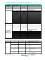
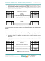
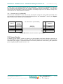
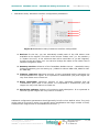
IntesisBox® Modbus Server Mitsubishi Heavy Industries Air Conditioning User’s Manual Issue Date: 14/05/2012 r1.0 eng Order Code: MH-AC-MBS-48 MH-AC-MBS-128 IntesisBox® Modbus Server – Mitsubishi Heavy Industries AC User’s Manual r1.0 eng © Intesis Software S.L. 2012 All Rights Reserved. Information in this document is subject to change without notice. The software described in this document is furnished under a license agreement or nondisclosure agreement. The software may be used only in accordance with the terms of those agreements. No part of this publication may be reproduced, stored in a retrieval system or transmitted in any form or any means electronic or mechanical, including photocopying and recording for any purpose other than the purchaser’s personal use without the written permission of Intesis Software S.L. Intesis Software S.L. Milà i Fontanals, 1 bis 08700 Igualada Spain TRADEMARKS All trademarks and trade names used in this document are acknowledged to be the copyright of their respective holders. © Intesis Software S.L. - All rights reserved This information is subject to change without notice ® IntesisBox is a registered trademark of Intesis Software SL URL Email tel http://www.intesis.com [email protected] +34 938047134 2 / 26 IntesisBox® Modbus Server – Mitsubishi Heavy Industries AC User’s Manual r1.0 eng Gateway for integration of Mitsubishi Heavy Industries air conditioning systems into Modbus (RTU and TCP) systems. Two models are available for this gateway, with the following Order Codes: MH-AC-MBS-48 Model supporting up to 48 indoor units. MH-AC-MBS-128 Model supporting up to 128 indoor units. © Intesis Software S.L. - All rights reserved This information is subject to change without notice ® IntesisBox is a registered trademark of Intesis Software SL URL Email tel http://www.intesis.com [email protected] +34 938047134 3 / 26 IntesisBox® Modbus Server – Mitsubishi Heavy Industries AC User’s Manual r1.0 eng Index 1. Description ...................................................................................................... 5 Introduction................................................................................................... 5 Integration signals .......................................................................................... 5 Functionality .................................................................................................. 6 Capacity of IntesisBox® ................................................................................... 7 2. Modbus interface of IntesisBox® ......................................................................... 8 2.1 Description .................................................................................................... 8 2.2 Functions supported ........................................................................................ 8 2.3 Modbus RTU .................................................................................................. 8 2.4 Modbus TCP ................................................................................................... 8 2.5 Address Map .................................................................................................. 8 2.5.1 Modbus addresses related to IntesisBox® ..................................................... 9 2.5.2 Modbus addresses related to each Indoor Unit .............................................. 9 2.5.3 Modbus addresses related to ALL indoor units ............................................. 10 3. IntesisBox® Device Connections ........................................................................ 11 3.1 Connect to Mitsubishi Heavy Industries Interface .............................................. 12 3.2 Connect to Modbus Interface .......................................................................... 12 3.2.1 Connect to Modbus RTU ........................................................................... 12 3.2.2 Connect to Modbus TCP ........................................................................... 13 3.2.3 Connect to PC (LinkBoxMB) ...................................................................... 14 3.3 Power Device ............................................................................................... 14 4. LinkBoxMB. Configuration & monitoring tool for IntesisBox® Modbus Server series ... 15 4.1 Introduction................................................................................................. 15 4.2 Connections configuration .............................................................................. 15 4.2.1 Configuration tab .................................................................................... 15 4.2.2 Modbus map tab ..................................................................................... 18 4.3 Sending the configuration to IntesisBox® ......................................................... 18 4.4 Signals viewer.............................................................................................. 19 4.5 Files ........................................................................................................... 20 5. Setup process and troubleshooting.................................................................... 21 5.1 Pre-requisites .............................................................................................. 21 5.2 Setup procedure ........................................................................................... 21 5.3 Troubleshooting ........................................................................................... 22 5.3.1 Physical checking .................................................................................... 22 5.3.2 Software checking .................................................................................. 22 6. Functional characteristics summary ................................................................... 23 7. Mechanical & Electrical characteristics ............................................................... 24 8. AC Unit Types compatibility.............................................................................. 25 9. Error codes .................................................................................................... 26 1.1 1.2 1.3 1.4 © Intesis Software S.L. - All rights reserved This information is subject to change without notice ® IntesisBox is a registered trademark of Intesis Software SL URL Email tel http://www.intesis.com [email protected] +34 938047134 4 / 26 IntesisBox® Modbus Server – Mitsubishi Heavy Industries AC User’s Manual r1.0 eng 1. Description 1.1 Introduction IntesisBox® Modbus Server – Mitsubishi Heavy Industries AC is a communication gateway for Mitsubishi Heavy Industries air conditioning (AC) systems to Modbus slave (RTU and TCP). This gateway allows integrating a Mitsubishi Heavy Industries AC system inside a supervision/control/automation system through PLC, SCADA and, in general, through any device or system with Modbus mastering (TCP or RTU) interface. The aim of this integration is to make accessible several Mitsubishi Heavy Industries air conditioning indoor units communicating with the Superlink protocol as if they were part of a Modbus system. Therefore, the IntesisBox® Modbus Server acts as a Modbus slave in the Modbus interface, allowing the Modbus master read and write in the Modbus registers. Moreover, IntesisBox® includes all hardware required to manage/control Mitsubishi Heavy Industries indoor units without extra components needed. 1.2 Integration signals Following is the list of parameters that can be monitored/controlled on the indoor units using IntesisBox®: For each indoor unit in the system: o Communication Status (read-only) o On/Off (R/W) o Operation Mode (R/W) o SetPoint Temperature (R/W) o Fan Speed (R/W) o Remote Controller Lock/Unlock (R/W) o Louver Control (R/W) o Room Temperature (read-only) o Filter Sign Status (read-only) o Error Code (read-only) o Compressor Status (read-only) o Filter Sign Reset (write-only) o Remote Controller Error Reset (write-only) o Thermo On/Off Status (read-only) Apart from these, the IntesisBox® also implements some extra signals (functions): 1 For all indoor units1 in the system: o HW Communication Status (read-only) o On/Off (write-only) o Operation Mode (write-only) o SetPoint Temperature (write-only) o Fan Speed (write-only) o Remote Controller Lock/Unlock (write-only) These signals work as master signals controlling all connected units at the same time © Intesis Software S.L. - All rights reserved This information is subject to change without notice ® IntesisBox is a registered trademark of Intesis Software SL URL Email tel http://www.intesis.com [email protected] +34 938047134 5 / 26 IntesisBox® Modbus Server – Mitsubishi Heavy Industries AC User’s Manual r1.0 eng 1.3 Functionality Each of the mentioned signals in section 1.2 is associated to a predefined and fixed Modbus address. Therefore, all the system is seen as a single Modbus slave unit with a fixed Modbus address map from the Modbus system point of view. 2-wire no polarity Superlink 0 1 EIA232/EIA485 IntesisBox Modbus Server 47 EIA232 TCP/IP 127 Figure 1.1 Integration of Mitsubishi Heavy Industries AC into Modbus system using IntesisBox® Two Modbus mode connection types can be active in IntesisBox®: Modbus RTU or Modbus TCP, or both simultaneously. IntesisBox® continuously polls all signals provided by each indoor unit and maintains the updated values to be served in Modbus. In the continuous polling of each indoor unit, if no response of a certain device is detected, the corresponding virtual signal inside the gateway will be activated indicating communication error between the gateway and that precise device (see 0). When a write order is done from Modbus in a gateway's write-enabled Modbus address, the corresponding order is sent to the associated Mitsubishi Heavy Industries signal (Superlink). Each Mitsubishi Heavy Industries Indoor Unit has a unique address (0 to 127). These addresses need to be configured inside IntesisBox® using the LinkBoxMB tool (see 4.2.2). IntesisBox® is capable of managing up to two simultaneous Modbus master connections. IntesisBox® includes all hardware needed to connect directly with the Mitsubishi Heavy Industries indoor units connecting with Superlink network. © Intesis Software S.L. - All rights reserved This information is subject to change without notice ® IntesisBox is a registered trademark of Intesis Software SL URL Email tel http://www.intesis.com [email protected] +34 938047134 6 / 26 IntesisBox® Modbus Server – Mitsubishi Heavy Industries AC User’s Manual r1.0 eng 1.4 Capacity of IntesisBox® Element Max. Number of indoor units 128 * Number of points per indoor unit Maximum number of points 14 1797* Maximum TCP master connections 2 Maximum RTU master connections 1 Notes Maximum number of AC indoor units that can be controlled Modbus addresses per indoor unit Valid Modbus addresses Maximum number of TCP simultaneous Modbus Master connections Maximum number of RTU simultaneous Modbus Master connections Table 1.1 IntesisBox® capacity * There are two different models of IntesisBox® Modbus Server – Mitsubishi Heavy Industries AC each one with different capacity. The table above shows the capacity for the top model (with maximum capacity). Their order codes are: MH-AC-MBS-48: Model supporting up to 48 indoor units For Superlink-I (Previous Superlink) or Superlink-II (New Superlink). Indoor Unit actual address range is 00 to 47 MH-AC-MBS-128: Model supporting up to 128 indoor units For Superlink-II (New Superlink) Indoor Unit actual address range is 000 to 127 Check available combination of Mitsubishi Heavy Industries Central Control and BMS interface units in the next tables. In the case of SL2NA or SL3NA, it is necessary to erase registration of non-connected indoor unit. For SL2NA and SL3NA, change is required for the setup deprived of the rights of instruction of Remocon control Lock/Unlock. New Superlink connections: MH-AC-MBS-128 MH-AC-KNX-128 SC-LGWNA-A SC-BGWNA-A/B etc. 1 Non connect MH-AC-MBS-48 MH-AC-KNX-48 SC-LGWNA-A SC-BGWNA-A/B etc. 1 Non connect SC-SL3NA-AE/BE etc. SC-SL2NA-E etc. SC-SL1N-E etc. Max Indoor Units Address No. 2 1 0 0 0-2 0-4 0-8 128 000-127 SC-SL3NA-AE/BE etc. SC-SL2NA-E etc. SC-SL1N-E etc. Max Indoor Units Address No. 2 1 0 0 0-2 0-4 0-8 48 00-47 Max Indoor Units Address No. Previous Superlink connections: MH-AC-MBS-48/128 MH-AC-KNX-48/128 SC-LGWNA-A SC-BGWNA-A/B etc. SC-SL3NAAE/BE etc. 1 Non connect Non connect © Intesis Software S.L. - All rights reserved This information is subject to change without notice ® IntesisBox is a registered trademark of Intesis Software SL SC-SL2NAE etc. 1 0 0 SC-SL1N-E etc. 0 1,2 0 URL Email tel 32 00-47 48 http://www.intesis.com [email protected] +34 938047134 7 / 26 IntesisBox® Modbus Server – Mitsubishi Heavy Industries AC User’s Manual r1.0 eng 2. Modbus interface of IntesisBox® 2.1 Description IntesisBox® acts as a slave device in the Modbus interface. The physical interface can be either Ethernet, if using Modbus TCP, or the EIA485 (or EIA232), if using Modbus RTU. 2.2 Functions supported This part is common for Modbus RTU and TCP: Modbus functions 03 and 04 (read holding registers and read input registers) can be used to read Modbus registers. Modbus function 06 (Single Multiple Holding Registers) must be used to write Modbus registers. As per Modbus standard specification, register contents are always expressed in MSB..LSB (Bid Endian). Modbus error codes are fully supported, they will be sent whenever a non-valid Modbus action or address is required (see section 9). 2.3 Modbus RTU Baud rate can be selected from 1200, 2400, 4800, 9600, 19200 and 38400. Information structure: Data Bits: 8 Parity Bit: Selectable from non, even, odd or second stop bit (2stop). Stop Bit: 1 Modbus slave number can be configured. Physical connection (EIA232 or EIA485) can also be selected. Only the lines RX, TX and GND of the EIA232 connector are used (TX and RX for EIA485). 2.4 Modbus TCP The TCP port to use can be configured (by default 502 is used). The IP address, subnet mask and default gateway address to use by IntesisBox® can be also configured. 2.5 Address Map Address map is fixed for each indoor unit and can be consulted as explained in the following tables. Please, remember that in the tables R/W stands for Read and Write, R stands for Read Only and W stands for Write Only. © Intesis Software S.L. - All rights reserved This information is subject to change without notice ® IntesisBox is a registered trademark of Intesis Software SL URL Email tel http://www.intesis.com [email protected] +34 938047134 8 / 26 IntesisBox® Modbus Server – Mitsubishi Heavy Industries AC User’s Manual r1.0 eng 2.5.1 Modbus addresses related to IntesisBox® (base addr is 1) Modbus register type (R/W) 2995 R Modbus address Signal description and values Hw Communication Status 0: No Hardware Communication Error 1: Hardware Communication Error 2.5.2 Modbus addresses related to each Indoor Unit1 Indoor unit number (base addr is 1) Modbus register type (R/W) 1 R 2 R/W Modbus address Signal description and values Communication Status 0: Communication OK 1: Communication ERROR Indoor Unit On/Off 0: Off 1: On Operation Mode 3 R/W 4 R/W 0: 1: 2: 3: 4: SetPoint Temperature Celsius value (16ºC to 30ºC) Fan Speed 5 R/W 6 R/W Cool Heat Fan Auto Dry 0: 1: 2: 3: Low Medium High Powerful Remote Controller Lock/Unlock 0: Remote Controller Locked 1: Remote Controller Unlocked Louver Control2 0 … 1 2 3 7 R/W 8 R 9 R 10 R 11 R 12 W 13 W 14 R … … 0: 1: 2: 3: 4: Swing Pos1 Pos2 Pos3 Pos4 Room Temperature Celsius value (0ºC to 30ºC) Filter Sign status 0:Off 1:On Error Code 0: No Error 0-99: Error Code3 Compressor Status 0: Off 1: On Filter Sign Reset 1: Clear Filter Alarm (When reading, always 0) Remote Controller Error Reset 1: Clear Remote Controller Error (When reading, always 0) Thermo On/Off Status (Inverter Type Only) 0: Off 1: On … Supported number of indoor units varies according to IntesisBox® model During transition between positions, Swing signal will turn on indicating the Louver is moving See list of indoor unit error codes and their meaning in section 9 © Intesis Software S.L. - All rights reserved This information is subject to change without notice ® IntesisBox is a registered trademark of Intesis Software SL URL Email tel http://www.intesis.com [email protected] +34 938047134 9 / 26 IntesisBox® Modbus Server – Mitsubishi Heavy Industries AC User’s Manual r1.0 eng Indoor unit number Modbus address (base addr is 1) Modbus register type (R/W) Signal description and values … … … … n* ( n*) x 20 + 1 ( n*) x 20 + 2 ( n*) x 20 + 3 ( n*) x 20 + 4 ( n*) x 20 + 5 ( n*) x 20 + 6 ( n*) x 20 + 7 ( n*) x 20 + 8 ( n*) x 20 + 9 ( n*) x 20 + 10 ( n*) x 20 + 11 ( n*) x 20 + 12 ( n*) x 20 + 13 ( n*) x 20 + 14 R R/W R/W R/W R/W R/W R/W R R R R W W R … … 2541 2542 2543 2544 2545 2546 2547 2548 2549 2550 2551 2552 2553 2554 R R/W R/W R/W R/W R/W R/W R R R R W W R … 127 (max number of supported indoor units depends on IntesisBox model) Communication Status Indoor Unit On/Off Operation Mode SetPoint Temperature Fan Speed Remote Controller Lock/Unlock Louver Control Room Temperature Filter Sign status Indoor Unit Error Code Compressor Status Filter Sign Reset Remote Control Error Reset Thermo Status (Inverter Type Only) … Communication Status Indoor Unit On/Off Operation Mode SetPoint Temperature Fan Speed Remote Controller Lock/Unlock Louver Control Room Temperature Filter Sign status Indoor Unit Error Code Compressor Status Filter Sign Reset Remote Control Error Reset Thermo Status (Inverter Type Only) *n is the indoor unit address number. 2.5.3 Modbus addresses related to ALL indoor units Indoor unit number Modbus address (base addr is 1) Modbus register type (R/W) 2996 W Signal description and values All Indoor Units On/Off 0: Off 1: On All Indoor Units Operation Mode ALL 2997 W 2998 W 0: 1: 2: 3: 4: Cool Heat Fan Auto Dry All Indoor Units SetPoint Temperature Celsius value (16ºC to 30ºC) All Indoor Units Fan Speed 2999 W 3000 W © Intesis Software S.L. - All rights reserved This information is subject to change without notice ® IntesisBox is a registered trademark of Intesis Software SL 0: 1: 2: 3: Low Medium High Powerful All Indoor Units Remote Controller Lock/Unlock 0: Remote Controller Locked 1: Remote Controller Unlocked URL Email tel http://www.intesis.com [email protected] +34 938047134 10 / 26 IntesisBox® Modbus Server – Mitsubishi Heavy Industries AC User’s Manual r1.0 eng 3. IntesisBox® Device Connections 4 5 6 7 8 9 10 3 11 2 1 Figure 3.1 IntesisBox® device front view 100-240VAC~ 50-60Hz 5W max FUSE: 250V 1.5A(T) 20x5mm 12 14 13 Figure 3.2 IntesisBox® device back view Next, there is the list with the device physical interface connector’s description 1.- Modbus RTU master EIA485 (C1) 2.- Modbus RTU master EIA232 (C2) 8.- Reset button (Non supported) 9.- Superlink selector (SLK) New: Superlink-II Old: Superlink-I 3.- Console serial port EIA232 10.- A-B connector 4.- Operation LED 11.- Modbus TCP master Ethernet (ETH) 5.- Error LED 12.- Power supply On/Off button 6.- Host LED 13.- Power supply fuse (250V, 1.5A) 7.- Pac LED 14.- Power supply connector © Intesis Software S.L. - All rights reserved This information is subject to change without notice ® IntesisBox is a registered trademark of Intesis Software SL (for Superlink, no polarity) URL Email tel http://www.intesis.com [email protected] +34 938047134 11 / 26 IntesisBox® Modbus Server – Mitsubishi Heavy Industries AC User’s Manual r1.0 eng 3.1 Connect to Mitsubishi Heavy Industries Interface Use the A-B connector in the right top corner of the front side of the IntesisBox® device in order to connect the Mitsubishi Heavy Industries network (Superlink) to the IntesisBox®. Recommended specifications of the cable for the Superlink are shown as follows: Size of cable : 0.75 to 1.25 square mm Max length of wiring : total 1000m (loop wiring is not allowed) Cable materials : Twisted Vinyl Cabtyre Cable Twisted Vinyl Cabtyre Cable Twisted Vinyl Cable for Control VCTF 2 core 0.75 to 1.25 square mm VCT 2 core 0.75 to 1.25 square mm CVV 2 core 0.75 to 1.25 square mm Table 3.1 Cable types recommended for Superlink connection For prevention of electromagnetic noise malfunctions, parallel wiring with the power line should be avoided Select the appropriate Superlink mode in the SLK selector. If you are using latest Air Conditioner of the Mitsubishi Heavy Industries network (New Superlink) select NEW, if not select OLD. LEDs placed in the top left corner will show connection status as follows: LED OP ERR HOST PAC Status Blinking Off Blinking Blinking IntesisBox® behavior Power supply OK No error Internal communication OK Communication with the Superlink network OK Table 3.2 IntesisBox® LED status information OP LED behavior must defer depending on the Superlink version, as shown in Figure 3.3 On Superlink-II Off On Superlink-I Off 1 sec Figure 3.3 OP LED blinking behavior depending on Superlink version If LEDs (except ERR) are not in the states described above, check section 5.3. For further information about the Superlink network, look up the Mitsubishi Heavy Industries Manual or contact your nearest Mitsubishi Heavy Industries supplier. 3.2 Connect to Modbus Interface 3.2.1 Connect to Modbus RTU Connect the communication cable coming from the Modbus RTU network to IntesisBox® device (see Figure 3.1). There are 2 existing modes available: © Intesis Software S.L. - All rights reserved This information is subject to change without notice ® IntesisBox is a registered trademark of Intesis Software SL URL Email tel http://www.intesis.com [email protected] +34 938047134 12 / 26 IntesisBox® Modbus Server – Mitsubishi Heavy Industries AC User’s Manual r1.0 eng EIA485 connection: Use the C1 connector (see Figure 3.1) if the Modbus interface is a 2-wire EIA485 connector. Connect the + and – to the respective port in the master device and in the IntesisBox® device (polarity matters). EIA232 connection: Use the C2 connector (see Figure 3.1) if the Modbus interface is point-to-point to one single master. IntesisBox (DB9 M) Cable (DB9 F) RX TX GND C2 Modbus RTU Connection EIA232 (Crossed) 2 3 5 2 3 5 Master RTU (DB9 M) Cable (DB9 F) RX TX GND Table 3.3 EIA232 cable pin assign Cable (2-wire) TX/RX+ TX/RX- EIA485 TX/RX+ TX/RXTable 3.4 EIA485 cable pin assign To check connectivity and correct functioning, use LinkBoxMB software (see LinkBoxMB User Manual). 3.2.2 Connect to Modbus TCP Connect the communication cable coming from the hub, switch or device of the Modbus Ethernet network to the ETH connector from the IntesisBox® device (see Figure 3.1). The cable to be used may vary depending on where the IntesisBox® is being connected: Connecting directly to a Modbus TCP master device: Crossover Ethernet UTP/FTP CAT5 cable. Connecting to a hub or switch of the LAN of the building: Straight Ethernet UTP/FTP CAT5 cable. IntesisBox (RJ45 F) Cable (RJ45 M) ETH Modbus TCP Connection Master TCP (RJ45 F) Cable (RJ45 M) 1 device Modbus master Ethernet Cable UTP/FTP Cat5 Crossover Cable UTP/FTP Cat5 Straight Hub N devices Modbus master Table 3.5 TCP cable connection © Intesis Software S.L. - All rights reserved This information is subject to change without notice ® IntesisBox is a registered trademark of Intesis Software SL URL Email tel http://www.intesis.com [email protected] +34 938047134 13 / 26 IntesisBox® Modbus Server – Mitsubishi Heavy Industries AC User’s Manual r1.0 eng In case there is no communication with the IntesisBox®, check that the Modbus TCP devices are operative and reachable from the network connection used by IntesisBox®. You can also check that the IntesisBox® Ethernet interface is sending Pings to its IP address using a PC connected to the same Ethernet network. 3.2.3 Connect to PC (LinkBoxMB) Connect the IntesisBox® device to the PC serial port using the serial cable provided. One end should be connected to the Console EIA232 port of the IntesisBox® device (see Figure 3.1) and the other end to the PC serial port. IntesisBox (DB9 F) Cable (DB9 M) TX RX GND EIA232 Serial Console PC Connection (LinkBoxMB) PC (DB9 M) EIA232 (Straight) Cable (DB9 F) RX TX GND 2 3 5 2 3 5 Table 3.6 EIA232 serial connection pin assign 3.3 Power Device To power up the device, what you need is to plug properly the Power Supply connector to the IntesisBox® device using a proper cable and connecting one end to the power supply connector (see Figure 3.2) and the other end to the power line. After that, just press the power supply On/Off button to turn it on. © Intesis Software S.L. - All rights reserved This information is subject to change without notice ® IntesisBox is a registered trademark of Intesis Software SL URL Email tel http://www.intesis.com [email protected] +34 938047134 14 / 26 IntesisBox® Modbus Server – Mitsubishi Heavy Industries AC User’s Manual r1.0 eng 4. LinkBoxMB. Configuration & monitoring tool for IntesisBox® Modbus Server series 4.1 Introduction LinkBoxMB is a Windows® compatible software developed specifically to monitor and configure IntesisBox® Modbus Server series. The installation procedure and main functions are explained in the LinkBoxMB User Manual. This document can be found in the Doc folder, or can be downloaded from the link indicated in the installation sheet supplied with the IntesisBox® device. In this section, only the specific case of Mitsubishi Heavy Industries indoor unit’s integration to Modbus networks will be covered. 4.2 Connections configuration To configure the IntesisBox®'s connection parameters and to see the points list, press on the Config button in the menu bar (see Figure 4.1). The Mitsubishi Heavy Industries Configuration window will open (see Figure 4.2). For integrations with large number of points, there is available an alternative CSV installation procedure explained in the LinkBoxMB User Manual. Figure 4.1 LinkBoxMB menu bar 4.2.1 Configuration tab Select the Connection tab to configure the connection parameters. Two subsets of information are shown in this window: Modbus RTU, Modbus TCP and Mitsubishi Heavy Industries interfaces parameters (see Figure 4.2). MHI interface configuration Modbus interface configuration Figure 4.2 LinkBoxMB configuration tab © Intesis Software S.L. - All rights reserved This information is subject to change without notice ® IntesisBox is a registered trademark of Intesis Software SL URL Email tel http://www.intesis.com [email protected] +34 938047134 15 / 26 IntesisBox® Modbus Server – Mitsubishi Heavy Industries AC User’s Manual r1.0 eng Next, there is an explanation for each of the configuration parameters in each mode. Modbus interface configuration parameters: 2 3 4 5 6 1 7 8 9 10 Figure 4.3 Modbus interface configuration 1. Select the type of Modbus communication to use (TCP, RTU or both). If Modbus TCP is selected, then: 2. IP IntesisBox: Enter the IP address for IntesisBox®. 3. Net Mask: Enter the IP netmask for IntesisBox®. 4. Gateway: Enter the default gateway address for IntesisBox®; leave it blank if no router is needed. 5. Port: Enter the TCP port to use (default for Modbus TCP is 502). 6. Timeout Keep Alive: Enter the time (expressed in seconds) that IntesisBox® will wait, upon no TCP activity, to send a Keep Alive packet. Enter 0 if you don’t want IntesisBox® to send any Keep Alive packet (default 30 seconds). If Modbus RTU is selected, then: 7. Connection: Select the physical media (EIA232 or EIA485)1. 8. Baud rate: Enter the baud rate of the serial communication. 9. Parity: Enter the byte parity of the serial communication. 10. Slave: Introduce the Slave number for the Modbus interface. 1 In the LinkboxMB this connection is labeled as RS232 and RS485 respectively. © Intesis Software S.L. - All rights reserved This information is subject to change without notice ® IntesisBox is a registered trademark of Intesis Software SL URL Email tel http://www.intesis.com [email protected] +34 938047134 16 / 26 IntesisBox® Modbus Server – Mitsubishi Heavy Industries AC User’s Manual r1.0 eng Mitsubishi Heavy Industries interface configuration parameters: 1 2 3 4 5 Figure 4.4 Mitsubishi Heavy Industries interface configuration 1. Devices: In this list, you can individually enable each of the 128 indoor units available on the system. The index in the column “Indoor unit” (i.e. the number x in “Indoor Unit xxx”) is the reference that will be used later on (in tab “Signals”) to refer to this AC indoor unit. You can also change the name of the indoor Unit to facilitate integration tasks. 2. Gateway version: Selection of the IntesisBox Modbus Server – Mitsubishi Heavy Industries gateway you are setting up. (128AC for MH-AC-MBS-128, 48AC for MHAC-MBS-48) 3. Timeout response: Maximum amount of time permitted before activating the Communication Error signal. It is expressed in milliseconds (ms) and ranges can vary from 2000 ms to 10000 ms. 4. Delay interframe: Maximum amount of time permitted between End Of Transmission (EOT) and a new frame. It is expressed in milliseconds (ms) and ranges can vary from 500 ms to 3000 ms. 5. Monitoring cadence: Cadence of monitoring and subscription. It is expressed in seconds (s) and ranges can vary from 60 s to 600 s. Additional configuration parameters should generally be left to their default value. They only might need to be tuned in some very specific cases (installations with large number of units, scenarios with large bursts of commands sent at once …) © Intesis Software S.L. - All rights reserved This information is subject to change without notice ® IntesisBox is a registered trademark of Intesis Software SL URL Email tel http://www.intesis.com [email protected] +34 938047134 17 / 26 IntesisBox® Modbus Server – Mitsubishi Heavy Industries AC User’s Manual r1.0 eng 4.2.2 Modbus map tab In order to know the Modbus map that is going to be used by the interface, the Modbus map tab can be consulted. Content in this tab is just informative: no information has to be set up. 1 2 3 4 Figure 4.5 Modbus signal list 1. Address Formula: Formula used by IntesisBox® to define the Modbus address for the point. Use this address (obtained with this formula) to access the point from your Modbus master device. 2. R/W: Indicates if the signal is read-only, or if it can be read and written (from the Modbus system point of view). 3. Signal: Signal description. 4. Values: Possible values for the signal. See section 2.5 for further detail on address mapping and the possible values on each signal. 4.3 Sending the configuration to IntesisBox® When the configuration is finished, follow the next steps. 1.- Click on Save button to save the project to the project folder on your hard disk (more information in LinkBoxMB User Manual). 2.- You will be prompted to generate the configuration file to be sent to the gateway. a.- If Yes is selected, the binary file (MHI.Lbox) containing the configuration for the gateway will be generated and saved also into the project folder. © Intesis Software S.L. - All rights reserved This information is subject to change without notice ® IntesisBox is a registered trademark of Intesis Software SL URL Email tel http://www.intesis.com [email protected] +34 938047134 18 / 26 IntesisBox® Modbus Server – Mitsubishi Heavy Industries AC User’s Manual r1.0 eng b.- If NO is selected, remember that the binary file with the project needs to be generated before the IntesisBox® starts to work as expected. 3.- Once in the configuration window again, click on exit. Configuration file is ready to be sent to the IntesisBox® device. 4.- Press the Send File button to send the binary file to the IntesisBox® device. The process of file transmission can be monitored in the IntesisBox® Communication Console window. IntesisBox will reboot automatically once the new configuration is loaded. After any configuration change, do not forget to send the configuration file to the IntesisBox® using button Send File. 4.4 Signals viewer Once the gateway is running with the correct configuration, to supervise the status of the configured signals, press the Signals button on the menu bar (see Figure 4.1). The Signals Viewer window will open (see Figure 4.6). This window shows all signals active within the gateway with its main configuration parameters and its real time value1 in the Value column. Figure 4.6 LinkBoxMB Signals Viewer The signals viewer can be used even though only one system is connected to the IntesisBox®, Modbus or Mitsubishi Heavy Industries AC. Therefore, it becomes convenient for supervision and testing the system. 1 In case you connect to the IntesisBox® when it’s been running for a certain time, you should press the Refresh button to get updated values. After pressing Refresh, all signal values will keep continuously updated until the connection is closed. © Intesis Software S.L. - All rights reserved This information is subject to change without notice ® IntesisBox is a registered trademark of Intesis Software SL URL Email tel http://www.intesis.com [email protected] +34 938047134 19 / 26 IntesisBox® Modbus Server – Mitsubishi Heavy Industries AC User’s Manual r1.0 eng In order to force a specific value to a signal, double-click its row in the table. This will display a dialog in which the desired value can be entered (see Figure 4.7). Changing its value in this way, will make: The content of the corresponding Modbus address will be changed to this value. If the signal is write-enabled, it will trigger a suitable command to Mitsubishi Heavy Industries AC system. Figure 4.7 Signal value change window 4.5 Files LinkBoxMB saves the integration configuration in the following files inside the project folder: PROJECT.INI INI file containing general information related to the project INI file containing information related with the values configured through the “Connection” tab in IntesisBox® configuration Binary file created from the information in the files described above. This is the file downloaded to the IntesisBox®. MHI.INI MHI.LBOX Table 4.1 LinkBoxMB generated files during Project creation It is strongly media, once configuration the hard disk recommended to back up the project folder containing these files in external the installation process is finished. This way you will be able to do future changes in case of reinstallation of LinkBoxMB due, for example, to a failure of in the PC where LinkBoxMB was installed. The configuration cannot be uploaded from the gateway to LinkBoxMB, it can only be downloaded. © Intesis Software S.L. - All rights reserved This information is subject to change without notice ® IntesisBox is a registered trademark of Intesis Software SL URL Email tel http://www.intesis.com [email protected] +34 938047134 20 / 26 IntesisBox® Modbus Server – Mitsubishi Heavy Industries AC User’s Manual r1.0 eng 5. Setup process and troubleshooting 5.1 Pre-requisites It is necessary to have the Modbus master device operative and well connected to the Modbus port of IntesisBox®. If using EIA232 communication, remember to respect the maximum of 15 meters cable distance. Connectors, connection cables, PC for LinkBoxMB, and other auxiliary material, if needed, are not supplied by Intesis Software for this standard integration. Items supplied by Intesis Software for this integration are: IntesisBox® Modbus Server device with full Mitsubishi Heavy Industries AC compatibility without extra components. Standard plug-in power supply 220Vac 50Hz to power IntesisBox® (European plug type). Access to LinkBoxMB software download site to configure IntesisBox®. Console cable needed to download the configuration to IntesisBox®. Product documentation. 5.2 Setup procedure 1. Install LinkBoxMB on your laptop, use the setup program supplied for this and follow the instructions given by the Installation wizard. 2. Install IntesisBox® in the desired installation site. For your convenience, check external enclosure measures (see 7) before deciding where to place the IntesisBox® device. 3. Connect the communication cable coming from the Modbus master device to the IntesisBox® port. Depending on the type of communication protocol: If EIA232 is used, connect it to C2. If EIA485 is used, connect it to C1. If Ethernet is used, connect it to ETH. (See 3.2 for more information on connection procedure) Remember that IntesisBox® can handle up to two simultaneous Modbus master connections. 4. Connect the Superlink network cable to the IntesisBox port marked as AB (see 3.1). 5. Select the appropriate Superlink mode in the SLK selector. If you are using latest Air Conditioner of the Mitsubishi Heavy Industries network select NEW, if not select OLD. Contact your nearest Mitsubishi Heavy Industries supplier in case of doubt. 6. Connect the IntesisBox® device to the power line (see 3.3) and press the On/Off button to turn it on. 7. Connect the communication cable coming from the serial port of your laptop/desktop PC to the IntesisBox® port marked as EIA232 Console (see 3.2.3). 8. Open LinkBoxMB and proceed as explained in section 4. © Intesis Software S.L. - All rights reserved This information is subject to change without notice ® IntesisBox is a registered trademark of Intesis Software SL URL Email tel http://www.intesis.com [email protected] +34 938047134 21 / 26 IntesisBox® Modbus Server – Mitsubishi Heavy Industries AC User’s Manual r1.0 eng 5.3 Troubleshooting If IntesisBox® is not working properly or even not working at all, please check the following conditions to be accomplished. 5.3.1 Physical checking First point to look at to make sure that IntesisBox® is not working properly is to check physical connections: 1.- Make sure that the power plug is correctly connected and current is available in the power line. 2.- Check IntesisBox® LED status: LED Status OP Off Blinking once perdiodicaly ERR HOST Off PAC Off Explanation Solution No power reaching the internal device Superlink communication failure Configuration error Check power connection Check fuse status (see 13 in Figure 3.2) Check Superlink cables and terminals (connectors, length of cables, etc.) Communication error in the Superlink network Check the Mitsubishi Heavy Industries Superlink network and its connections Download the binary file again (see 4.3) Table 5.1 IntesisBox® LED status information 5.3.2 Software checking Once physical connections have been checked, if functioning problems still remain, please use the LinkBoxMB tool to monitor the working status of the device. To check the Modbus communication status, click on the Modbus button in the menu bar (see Figure 4.1). To check the MHI communication status, click on the MHI button, also in the menu bar (see Figure 4.1). To check the signal values in the Modbus registers, click on the Signals button, also in the menu bar (see Figure 4.1). Further information regarding the monitoring procedure and the information provided in each window can be consulted in the LinkBoxMB Manual. © Intesis Software S.L. - All rights reserved This information is subject to change without notice ® IntesisBox is a registered trademark of Intesis Software SL URL Email tel http://www.intesis.com [email protected] +34 938047134 22 / 26 IntesisBox® Modbus Server – Mitsubishi Heavy Industries AC User’s Manual r1.0 eng 6. Functional characteristics summary General Max. Number of Mitsubishi Heavy Industries interfaces Virtual signals Modbus interface Device type Modbus modes supported Modbus TCP configuration parameters Modbus RTU configuration parameters Points Configuration Supported Modbus function codes Two different versions of IntesisBox® available, supporting a maximum of 128 and 48 indoor units respectively. One communication error virtual signal per every single Mitsubishi Heavy Industries AC All these virtual signals are available from Modbus. Slave. TCP, RTU EIA232 or EIA485. IP address. Subnet mask. Default gateway address. TCP port. EIA232/EIA485. Baud rate. Parity. Slave number. AC system related fields. Indoor unit main address: Main Address of the indoor each AC indoor unit Modbus memory block relates to. Read functions: 3- Read holding registers. 4- Read input registers. Write functions: 6- Write single registers. If poll records are used to read multiple records, the range of addresses requested must contain valid addresses, otherwise the corresponding Modbus error code will be responded. Modbus data coding All the point's values are coded in 2 byte registers (even if their possible values are 0 and 1). They are expressed in MSB..LSB format (Big Endian) © Intesis Software S.L. - All rights reserved This information is subject to change without notice ® IntesisBox is a registered trademark of Intesis Software SL URL Email tel http://www.intesis.com [email protected] +34 938047134 23 / 26 IntesisBox® Modbus Server – Mitsubishi Heavy Industries AC User’s Manual r1.0 eng 7. Mechanical & Electrical characteristics 179 mm 65 mm 215 mm 61 mm 167 mm Figure 7.1 External dimensions – Perspective view 61 mm 65 mm 4 mm Figure 7.2 External dimensions – Front view 195 mm Ø 5 mm 15 mm 138 mm 10 mm Figure 7.3 Top view1 (screw holes size) 1 Device can be installed in any position. © Intesis Software S.L. - All rights reserved This information is subject to change without notice ® IntesisBox is a registered trademark of Intesis Software SL URL Email tel http://www.intesis.com [email protected] +34 938047134 24 / 26 IntesisBox® Modbus Server – Mitsubishi Heavy Industries AC User’s Manual r1.0 eng Mounting Industrial sheet metal. Size: 215mm x 167mm x 61mm. Weight: 2.025 Kg Gray metalized. 100 to 240VAC~ 50 to 60Hz 5W max. Power connector: C14 (male) 1 250V 1.5A Dimensions: 20x5mm Per terminal: solid wires or stranded wires (twisted or with ferrule) 1 core: 0.75 … 1.25mm2 2 cores: 0.75 … 1.25mm2 3 cores: not permitted Wall (see Figure 7.3) Modbus TCP port 1 x Ethernet 10Base-T (RJ45). Enclosure Color Power Fuse Terminal wiring (for low-voltage signals) Modbus RTU ports A-B port LED indicators Push buttons Selectors Console port Configuration Firmware Operational temperature range Operational humidity range Protection RoHS conformity Norms and standards 1 x Serial EIA232 (DB9 male DTE). SELV 1 x Serial EIA485 (Plug-in screw terminal block 2 poles). SELV 1 x Superlink terminals (Plug-in screw terminal block 2 poles “A” “B”). SELV 2 x Ethernet port link and activity (LNK, ACT). 4 x MHI Interface (OP, ERR, HOST, PAC) 1 x Reset Device 1 x SLK selector EIA232. (DB9 female DCE). SELV Via console port. 2 Allows upgrades via console port. 0°C to +40°C 5% to 95%, non condensing IP20 (IEC60529). Compliant with RoHS directive (2002/95/CE). CE conformity to EMC directive (2004/108/EC) and Low-voltage directive (2006/95/EC) EN 61000-6-2 EN 61000-6-3 EN 60950-1 EN 50491-3 Table 7.1 IntesisBox® Mechanical and Electrical Characteristics 8. AC Unit Types compatibility Indoor units compatible with the IntesisBox® Modbus – Server are those included in the Mitsubishi Heavy Industries KX family and so on. 1 2 A power cable with connector C14 male 1.6 meters long is supplied with the device. Standard cable DB9male-DB9female 1.8 meters long is supplied with the device for connection to a PC COM port for configuring ® and monitoring the device. The configuration software, compatible with Windows operating systems, is also supplied. © Intesis Software S.L. - All rights reserved This information is subject to change without notice ® IntesisBox is a registered trademark of Intesis Software SL URL Email tel http://www.intesis.com [email protected] +34 938047134 25 / 26 IntesisBox® Modbus Server – Mitsubishi Heavy Industries AC User’s Manual r1.0 eng 9. Error codes This list contains all possible values shown in Modbus registers for “Error Code” for each indoor unit. Error Code Modbus 0 1 2 3 5 6 7 8 9 Error in Remote Controller N/A E1 E2 E3 E5 E6 E7 E8 E9 10 E10 12 14 16 19 28 30 31 32 33 35 36 37 38 39 40 41 42 43 45 46 47 48 49 51 53 54 55 56 57 58 59 60 61 63 E12 E14 E16 E19 E28 E30 E31 E32 E33 E35 E36 E37 E38 E39 E40 E41 E42 E43 E45 E46 E47 E48 E49 E51 E53 E54 E55 E56 E57 E58 E59 E60 E61 E63 Error Description No active error Remote controller communication error Duplicated indoor unit address Outdoor unit signal line error Communication error during operation Indoor heat exchanger temperature thermistor anomaly Indoor return air temperature thermistor anomaly Heating overload operation Drain trouble Excessive number of indoor units (more than 17) by controlling one remote controller Address setting error by mixed setting method Communication error between master and slave indoor units Indoor fan motor anomaly Indoor unit operation check, drain motor check setting error Remote controller temperature thermistor anomaly Unmatched connection of indoor and outdoor unit Duplicated outdoor unit address No. Open L3 Phase on power supply at primary side Inverter primary current error Cooling overload operation Discharge pipe temperature error Outdoor heat exchanger temperature thermistor anomaly Outdoor/Ambient air temperature thermistor anomaly Discharge pipe temperature thermistor anomaly High pressure error Power transistor overheat Current cut Excessive number of indoor units connected, excessive total capacity of connection Communication error between inverter PCB and outdoor control PCB Mixed address setting methods coexistent in same network Inverter over-current error Outdoor DC fan motor anomaly Low pressure anomaly Inverter anomaly Suction pipe temperature thermistor anomaly High/Low pressure sensor anomaly Underneath temperature thermistor anomaly Power transistor temperature thermistor anomaly Insufficient in refrigerant amount or detection of service valve closure Anomalous compressor by loss of synchronism Compressor startup failure Rotor position detection failure / Anomalous compressor rotor lock Communication error between the master unit and slave units Emergency stop Table 9.1 Error codes In case you detect an error code not listed, contact your nearest MITSUBISHI HEAVY INDUSTRIES technical support service. © Intesis Software S.L. - All rights reserved This information is subject to change without notice ® IntesisBox is a registered trademark of Intesis Software SL URL Email tel http://www.intesis.com [email protected] +34 938047134 26 / 26