1
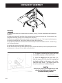
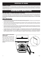
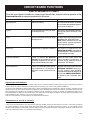
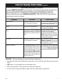
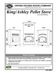
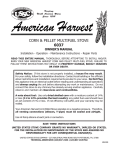
Keeping
North America W arm
Since 1869
CORN & PELLET MULTIFUEL STOVE
6039, 6039T
OWNER’S MANUAL
Installation - Operation - Maintenance Instructions - Repair Parts
READ THIS ENTIRE MANUAL, THOROUGHLY, BEFORE ATTEMPTING TO INSTALL AND/OR
BURN YOUR NEW AMERICAN HARVEST CORN AND PELLET MULTI-FUEL STOVE. FAILURE TO
FOLLOW THESE INSTRUCTIONS MAY RESULT IN PROPERTY DAMAGE, BODILY INJURIES
OR EVEN DEATH.
Safety Notice: If this stove is not properly installed, a house fire may result.
For your safety, follow the installation directions. Contact local building or fire officials
about restrictions and installation requirements peculiar to your area. Do Not Plug
this appliance into an electrical outlet before reading and understanding all operations
and always unplug the unit before attempting any work or maintenance. Do not
connect this stove to any chimney flue already serving another appliance. Carefully
observe and maintain all clearances to combustibles.
A note about fuel: Use only dried shelled corn with a moisture content of 14%
or less (11 to 12% provides the best results); any pellet fuel used should have
an ash content of 1% or less. If not, efficiency will suffer, and your warranty may be
voided.
Your American Harvest Corn/Pellet Stove operates on a negative pressure. Therefore,
all venting connections (elbows, T-pipe) must be sealed and airtight.
Use Hi-Temp silicone at each joint or connection.
SAVE THESE INSTRUCTIONS
UNITED STATES STOVE COMPANY GRANTS NO WARRANTY, IMPLIED OR STATED,
FOR THE INSTALLATION OR MAINTENANCE OF THE STOVE AND ASSUMES NO
RESPONSIBILITY FOR ANY CONSEQUENTIAL DAMAGE(S).
UNITED STATES STOVE COMPANY - 227 INDUSTRIAL PARK ROAD-SOUTH PITTSBURG, TN. 37380
TECHNICAL ASSISTANCE (423) 837-2100 - (423) 837-2109 FAX
USSC
851621B1
CONGRATULATIONS!
You've purchased one of America's Finest Multifuel Burning
Stoves. By heating with fuels such as corn and pellets, you're
helping CONSERVE AMERICA'S ENERGY!
NOTE: YOUR UNIT MUST BE INSTALLED BY A
QUALIFIED INSTALLER, such as an NFI Certified
Specialist
We strongly suggest installing smoke detectors in your home if not already installed.
Initial burn off may cause slight smoke and odor the first few hours of operation.
Operate outside if possible
SPECIFICATIONS
United States Stove Company (manufacturer of the American Harvest Multifuel Pellet
Stove) reserves the right to alter products, specifications and price without notice.
Safety Tested & Listed to ASTM- E 1509, ULC-C 1482, (UM) 84-HUD, by OMNI Test Laboratories,
Inc., Beaverton, Oregon USA
Heat Input, Maixmum
52,200 BTU/HR
Heat Output, Maximum ,
48,280 BTU/HR
Heating Capacity
1,200 Sq. Ft 0
Fuel Storage Capacity
60 Lbs.
Width
29 in./737mm
Height
31 in./787mm
Depth
28 in./711mm
, BTU output will vary, depending on the brand, type and quality of fuel and the moisture content. Consult your dealer
for best results.
0 Based on post 1982 home construction, requiring 35 BTU/Hr per Sq. Ft.
Remember, this stove should not be used as the only source of heat in the house. Power outages
and periodic maintenance will result in a total loss of heat.
2
USSC
6039&6039T ASSEMBLY
Assembly
1. Unpack unit and make sure all components are included; (4) Legs, (2) Ash Pan Guide Rails and all hardware for
installation.
2. Inside the unit are two(2) Ash Dump Covers located to the left and right of the burnpot. Remove these for leg
and guiderail assembly. (See pg. 15 for ash dump cover desciption)
3. Fold the corner padding from the carton and lay it on the floor behind the unit. This is used to hold the heater up
off the floor to install the legs. Gently tilt the heater on its back, door opening up.
4. Assemble the guiderails to the heater with the bottom flanges turned to the outside as shown. Use the four(4)
#10 Tek Screws provided.
5. Assemble the legs using the eight(8) Bolts as shown.
6. After all bolts and screws have been tightened properly, set the heater back up on the legs and replace the two
ash dump covers. (See pg. 15 for ash dump cover placement)
1. The Auger is packed in the hopper and must
be installed properly as illustrated below.
2. Insert the Auger into the auger tube. Rotate the auger until it fits into the coupling that
is already installed on the auger motor drive.
Seat the auger firmly. The Auger cannot be
turned by hand once installed properly.
NOTE:
Initial burn off may cause slight smoke and
odor the first few hours of operation.
Operate outside if possible
Continue with Installation
USSC
3
SAFETY STEPS
IMPORTANT: Proper installation of this stove is necessary for safe and efficient operation.
Installing this product improperly may result in a house fire and personal injury. All applicable
building codes for your location must be followed. In areas where building codes require additional
steps to the installation of this product not included in this manual the building codes will take
precedent and must be followed. Contact your local building inspector to obtain any necessary
permits or inspection guidelines before installing the product.
•
The American Harvest stove is designed to burn dry shelled corn, cherry pits, or pelletized fuel such as
wood pellets. The burning of other solid fuels such as cord wood or wood chips in this stove is not
permitted.
•
This product requires simple periodic maintenance for proper operation and long life of the stove. Read
and follow the maintenance schedule closely.
•
DISCONNECT THE POWER CORD BEFORE SERVICING THIS STOVE!
•
A power surge protector is required. The unit must be plugged in to a grounded 110-volt power
source. Circuit Boards are very expensive - protect yours!
•
Always route the power cord away from the unit. Do not route cord in foot traffic areas. Do not pinch
cord under furniture.
•
A working smoke detector must be installed in the same room as this product.
•
Flammable or explosive liquids such as gasoline, naphtha, alcohol or engine oil must NEVER be used in or
around this stove. These liquids must be stored well away from this stove as the open flame in the
burner chamber could ignite the fumes of such liquids. Do not burn garbage in this unit.
•
The moving parts of this stove are propelled by high torque electric motors. The auger and Fuel Agitator
can cause severe injury to body parts that may get near them. Keep all body parts away from the
auger and Fuel Agitator while the stove is plugged into an electrical outlet. These moving parts may
begin to move at any time while the stove is plugged in.
•
According to HUD requirements, when installed in a mobile home, this stove must be grounded directly to
the steel chassis of the mobile home and bolted to the floor. Direct air access must be provided - Use
67FAK Fresh Air Kit
•
This stove is not intended for use in commercial installations.
•
Do not connect this stove to “B” vent. Use UL Listed Pell Vent ONLY!
BURNING SOLID FUELS
Ashes will have to be Removed from the stove periodically. See cleaning procedure.
Your American Harvest stove, due to the nature of solid fuels, will require brief periodic attention. Please do not expect
to light your stove and walk away from it. A few moments of adjustment and cleaning from time to time is an important part
of burning solid fuels, due to the vast differences in fuel, humidity and outside temperature.
The American Harvest stove has been designed to burn dry shelled corn, wood pellets and other pelletized fuels that meet
Association of Pellet Fuel Industries standards.
4
USSC
BURNING SOLID FUELS
continued...
SHELLED CORN (Dry, preferably corn with 11- 12% moisture content)
•
Corn must contain less than 14% moisture content. Wet corn will rapidly deteriorate stove components, reduce
efficiency and void all warranties. Purchase a moisture tester if in doubt.
•
Corn must be clean and free from debris. Never burn corn right from the field. Damage caused by dirty corn is not
covered by the product warranty. Ask for clean filtered bagged corn only. Stalk parts, excessive fines and cob
remnants will clog the auger.
•
NEVER BURN SEED CORN IN YOUR STOVE. Seed corn is treated with chemical pesticides that are harmful or fatal if
swallowed, therefore, seed corn is dangerous to have in the house, especially where children can reach it.
•
Never burn “Deer Corn.” It frequently contains molasses/sugars.
•
Store your corn supply in a dry place and keep bags or container sealed to prevent your corn from absorbing excess
moisture. Test the moisture content periodically to ensure the proper dryness.
•
There are many varieties of corn grown around the world. Each variety has unique characteristics including the shape
and size of the kernel. Your stove will burn more consistently with a small to midsize kernel corn. If the kernel size of
the corn varies greatly or if you switch sources frequently, you will get a less consistent burn. Therefore, purchasing
corn from the same source will help achieve a more consistent burn. DO NOT USE CORN WITH A HIGH WAX
CONTENT!
WOOD PELLETS
•
As with corn, be consistent in your pellet supplier. Pellets will vary in content and burn characteristics from supplier to
supplier. A consistent supply of pellets will result in a more consistant and effencient burn.
•
Check your pellets for foreign objects. Your stove warranty will not cover damage done to your stove due to foreign
objects in the fuel supply.
•
Store your pellets in a dry place to prevent them from absorbing added moisture.
•
To decrease sawdust buildup, the hopper will need to be vacuumed out after every 6-8 bags of pellets or more often if
the pellets are poor quality. You may have to screen each bag of pellets if sawdust becomes a problem.
•
Wood Pellets vary in size and ash content from less than 1% to 3% or more. Your stove will burn more efficiently with
small to midsize pellets. Low ash content pellets will allow you to burn the stove longer between cleanings. Only wood
pellets manufactured to the Association of Pellet Fuel Industries (A.P.F.I.) standard for residential pellets fuels are
recommended. Performance will suffer if nonstandard pellets are used. Consult your local American Harvest reseller
for more information on approved wood pellet fuel.
CAUTION: DO NOT PLACE SUCH FUELS WITHIN THE SPACE HEATER’S INSTALLATION CLEARANCES OR WITHIN THE SPACE REQUIRED FOR CHARGING AND ASH
REMOVAL.
INSTALLATION REQUIREMENTS
FLOOR PROTECTION
The American Harvest Multifuel Stove may be installed on a combustible floor, with proper floor protection, or
on a masonry hearth. The hearth or noncombustible floor protector must extend a minimum of (6) inches (152mm)in
front and (6) inches (152mm) from each side of the ash removal door.
USSC
5
CLEARANCES TO COMBUSTIBLES
The stove must be installed with the following minimum clearances to side and back wall combustible materials. NOTE:
These are minimum clearances to combustible walls established by the testing lab. The amount of room needed on the left
side of the unit to access the electrical panel is (6) six inches (152mm).
PARALLEL - A BCDECORNER - F G-
Left Sidewall to Top Edge of Unit
Sidewall to Flue
Backwall to Flue
Backwall to Unit
Right Sidewall to Top Edge of Unit
Adjacent Wall to Flue
Adjacent Wall to Unit
6 in./152mm
5 in./127mm
3 in./75mm
9 in./228mm
2 in./50mm
3 in./75mm
4 in./100mm
BACK WALL
SIDE WALL
SIDE WALL
BACK WALL
Backwall / Sidewall
Parallel
Corner Installation
NOTE:
Allow sufficient space to remove the left and right side panels for maintenance purposes.
6”
min.
6”
min.
HEARTH PROTECTION
6”
min.
These clearances must be maintained and may only be reduced by means approved by the regulatory authority
6
USSC
GUIDELINES FOR EXHAUST VENTING SYSTEMS DESIGN
It is recommended that only an authorized installer install your pellet/corn stove, preferably an NFI certified
specialist. The following installation guidelines must be followed to ensure conformity with both the safety listing of this
stove and to local building codes.
INSTALL VENT AT CLEARANCES SPECIFIED BY THE VENT MANUFACTURER.
•
A UL listed 3” or 4” type “PL” pellet vent exhaust system must be used for installation and attached to the pipe connector
provided on the back of the stove. Use a 3” to 4” adapter for 4” pipe. A cap must be used at the termination of type “L”
vent chimneys. 4” PL is required for elevations above 2,500 feet above sea level.
•
Do not terminate vent in any enclosed or semi-enclosed area, such as; carports, garage, attic, crawl space, under a
sundeck or porch, narrow walkway or close area, or any location that can build up a concentration of fumes such as a
stairwell, covered breezeway etc.
•
Vent surfaces can get hot enough to cause burns if touched by children. Noncombustible shielding or guards may be
required.
•
Do not install a flue damper in the exhaust vent of this unit.
•
Termination must exhaust above air inlet elevation. Installation MUST include three (3) vertical feet of pellet vent pipe.
This will create some natural draft to prevent the possibility of smoke or odor during appliance shutdown and to keep
exhaust from causing a nuisance or hazard from exposing people or shrubs to high temperatures. Do not connect
this unit to a chimney flue serving another appliance. Do not connect directly to a masonry chimney.
•
The installation must include a cleanout tee to enable collection of fly ash and to permit periodic cleaning of the exhaust
system. 90° elbows accumulate fly ash and soot thereby reducing exhaust flow and performance of the stove. Each
elbow or tee reduces draft potential by 30% to 50%. Use no more than 180 degrees of elbows (two 90-degree elbows,
or two 45-degree and one 90-degree elbow, etc.) to maintain adequate draft. Clean-out tees and elbows should not
be mounted directly to the rear of the stove.
•
Total length of horizontal vent must not exceed 48”(4ft.)/1,200mm. The maximum recommended vertical venting
height is 12-feet for 3-inch type “PL” vent. All joints in the vent system must be fastened by at least 3 screws, and all
joints must be sealed with RTV silicone sealer to be airtight.
•
The area where the vent pipe penetrates to the exterior of the home must be sealed with silicone or other means to
maintain the vapor barrier between the exterior and the interior of the home.
NOTE: These are guidelines only. Proper venting is accomplished by design and common sense. In most
installations 3 inch diameter venting is adequate. If it does not vent properly you will have to change it to
4 inches. You should not exceed 4 inch diameter venting.
DO NOT CONNECT TO ANY AIR DISTRIBUTION DUCT OR SYSTEM
VENT TERMINATION CLEARANCES:
A) Min. 4-ft clearance below or beside any door or window
that opens.
B) Min. 1-ft clearance above any door or window that
opens.
C) Min. 3-ft clearance form any adjacent building.
I
D) Min. 7-ft clearance from any grade when adjacent to
public walkways.
E) Min. 2-ft clearance above any grass, plants, or other
combustible materials.
F) Min. 3-ft clearance from an forced air intake of any
appliance.
G) Min. 2-ft clearance below eves or overhang.
H) Min. 1-ft clearance horizontally from combustible wall.
Must be a minimum of 36-inches above the roof
and 24-inches above the highest point or the roof
within 10-feet.
USSC
A
F
B
C
H
D
A
F
E
7
DESIGN GUIDELINES FOR OUTSIDE COMBUSTION AIR CONNECTION
1) For installations with horizontal through-the-wall exhaust, it is strongly recommended that the stove combustion air be
connected to the outside. If the home is newer or has been tightly insulated it is required to install outside combustion
air.
2) Connection to outside the house is REQUIRED for mobile home installations. We strongly urge use of the 67FAK Fresh
Air Kit.
90 DEGREE BEND TERMINATION
WIND HOOD TERMINATION
Wind Hood
2” Min. Diameter
3”
NOTE:
A wire mesh screen with a
maximum opening size of 3/8”
must be installed.
2”
6”
3) Only noncombustible pipe 2 inches (or greater) in diameter is approved to use for outside air connections (straight or
flexible). PVC pipe is NOT approved and should NEVER be used.
4) If the air inlet is connected to the outside, it MUST be terminated with a vertical 90-degree bend (down) or with a wind
hood. Failure to do so could result in a burn back during high winds blowing directly up the air inlet during a simultaneous power failure (see diagram above).
5) Blockage, excessive length, or extra bends in the air intake pipe will starve the stove of combustion air. A 90-degree
bend is equivalent in restriction to approximately 30 inches of straight inlet pipe.
CAUTION: The operation of exhaust fans such as bath room fans, attic fans, etc. might starve the heater of combustible air
creating a negative pressure in the room. Provide adequate ventilation in the room accompanying the heater. If not, the
pressure switch may shut off operation of the heater. (Due to negative pressure)
8
USSC
INSTALLATION CONFIGURATIONS
Note: Where passage through a wall, or partition of combustible construction is desired, the installation
shall conform to CAN/CSA -B365
The American Harvest Corn/Pellet Stove Model 6039/6039T may be installed as follows:
1) A freestanding unit
MOBILE HOME INSTALLATION REQUIREMENTS
IN ADDITION TO THE STANDARD INSTALLATION INSTRUCTION, THE FOLLOWING
REQUIREMENTS ARE MANDATORY FOR INSTALLATION IN A MOBILE HOME:
WARNING
DO NOT INSTALL IN SLEEPING ROOM
1)
2)
3)
4)
5)
Stove must be permanently bolted to the floor. Remove the Base Trim and bolt thru the base flange.
Stove must have permanent outside air source. (67FAK)
Stove must be permanently electrically grounded to the steel chassis of the mobile home.
All vertical chimney vent must have wall supports.
All exhaust systems must have a spark arrestor.
CAUTION
THE STRUCTURAL INTEGRITY OF THE MOBILE HOME FLOOR, WALL AND CEILING/
ROOF MUST BE MAINTAINED.
Check with your local building official as other codes may apply.
FREESTANDING STOVE INSTALLATION REQUIREMENTS
General Horizontal Exhaust Termination (Follow manufacturer’s instructions):
1) Locate proper position for the type “PL” wall thimble (F).
2) Use a saber saw or keyhole saw to cut a 7 1/4-inch diameter hole through the wall (E) for a 3-inch pipe. For a 4-inch
pipe, cut an 8 1/4-inch hole. Install the wall thimble (F)in the hole. The size of hole opening will vary with brand of wall
thimble.
3) Position stove approximately 12” from the wall on the noncombustible floor pad. Push the type “PL” pipe (B) through the
wall thimble (D). Squeeze a bead of high temperature RTV silicone sealer (A) around the outside of the 3” diameter
exhaust pipe approximately ½” from the stove back panel. Firmly push on a section of type “PL” pipe (B) until the inner
pipe liner pushes up against the bead of RTV sealer. Don’t seal the entire 3” diameter pipe as you will not be able to
disassemble the pipe at a later date. The bead of silicone will act as a gasket right on the end of the 3” pipe (B).
Alternate Method: An approved type “PL” connector back clamp may be used to allow easy disconnect for maintenance. (The RTV sealant must be used in mobile home installation)
4) Push stove with pipe attached towards wall. Pipe (B) will go through the wall thimble (F). Be careful not to dislodge the
thimble. Position stove not closer than 9” to the wall.
5) Install type “PL” termination cap (G) with rodent screen cap (optional) on outside end or pipe. Note: The end of the
exhaust pipe must extend a minimum of 12 inches from the outside of the building. Rodent screen cannot be less than
3/8” opening mesh.
6) If installing with combustion air from outside, cut a separate hole through the wall for the fresh air tube (C). This tube
must be 2” minimum diameter pipe. Connect outside air pipe inlet on stove. This tube must be terminated with a 90
degree elbow or hood.
USSC
9
Note: Always check dimensions on unit before cutting hole in wall
3’ Minimum
Vertical Pipe
6039 - PEDESTAL UNIT
EXHAUST OULET
3" DIA.
12 1/8
10 1/16
6039T - LEG UNIT
COMBUSTION
AIR INTAKE
1 7/8" DIA.
11 3/4
EXHAUST OUTLET
3' DIA
12
10 1/16
COMBUSTION
AIR INTAKE
1 7/8" DIA
11 5/8
Dimensional tolerance
±0.25”
10
USSC
Termination Cap
NOTE:
Vertical Pipe must be
4” PL Above 4’
9” Min.
Support Bracket
Wall Thimble
Tee
6” Min.
Clean Out Cover
Non Combustible Hearth Plate
The Hearth Pad is not required under the unit if the floor is noncombustible but is required 6 inches (152mm) beyond the
front of the unit and 6 inches (152mm) beyond each side of the door if the floor is a combustble floor. wood flooring, carpet,
linoleum, etc.
THROUGH THE WALL, VERTICAL PIPE INSTALLATION WITH TERMINATION CAP
USSC
11
GLASS MAINTENANCE, REMOVAL AND REPLACEMENT
Your American Harvest Corn/Pellet Stove comes to you with the glass door installed in place, ready for use. The
glass is surrounded on the edges with a gasket and seated in a glass channel. It is held in place with four (2) clips.
REMOVAL OF BROKEN OR DAMAGED CERAMIC GLASS
Open the door and lift off of hinges. If the door is tight, tap gently on the bottom of the door with your hand or rubber
hammer. Lay door down on newspaper with glass clips facing you. Using a #2 Phillips screwdriver, loosen the screws
and take off the glass clips. Remove the broken glass carefully and discard.
Reverse the above procedure for replacing new glass with new gasket.
WARNING
Do not operate unit with broken glass.
Do not substitute original factory glass.
You must use only factory authorized glass;
Do not slam door shut.
Do not strike glass.
Do not use abrasive cleaners.
Do not clean when glass is hot.
CLEANING THE GLASS
When the fire is first started, it will produce some smoke. The smoke might accumulate on the glass surface. Before the
fire gets hot, open the door and wipe the glass surface off with a damp rag. Do not touch the surface with your hands.
If after constant use, the glass is dirty, you must clean the glass so that it will not become etched with the fly ash. When
the glass has cooled off, take a damp rag, put a little fly ash from the unit on it and clean the glass. If this does not clean
the glass use a non-abrasive spray; 409 works well.
.
GLASS CLIPS
12
USSC
LIGHTING INSTRUCTIONS
CAUTION: DO NOT USE CHEMICALS OR FLUIDS TO START THE FIRE
HOT WHILE IN OPERATION. KEEP CHILDREN, CLOTHING AND FURNITURE AWAY. CONTACT MAY CAUSE SKIN
BURNS.
Before lighting your American Harvest for the first time, make sure that all items
are out of the hopper, ash pan and firebox area. Press the “On” button and allow
your American Harvest to run for at least 4 minutes, to check for proper operation.
Once your American Harvest is started, you will notice the exhaust blower starts
immediately. If you press the “Heat Setting” button up, the exhaust blower changes
speed, increasing speed the higher the heat setting. After 3 minutes, the auger and
agitator will start rotating. Note: The distribution blower will not operate at this
time, as a temperature of at least 110 degrees must be reached before operating. If
proper operation of your American Harvest is confirmed, you can add fuel to the
hopper and allow the auger to purge the fuel to the firepot.
TO START:
• Turn the American Harvest to the “OFF” position and place a small handful of
wood pellets or fire starting pellets (Pellets that already contain fire starter) in the
firepot.
• Squirt only a small amount of fire starter gel on top of the wood pellets (NOT
necessary if using fire starting pellets).
• Light the fire starter and wait approx. 1-minute for it to start actively burning.
• Press the “On” button and adjust the heat setting to read “2”. This will automatically match your feed rate with the
proper combustion air. As you increase the heat setting, your feed rate and combustion air increase together.
NOTE: Even if you are burning corn or other fuels in your unit, wood pellets make an excellent source of
starter fuel. Corn takes too much starter to get lit and up to temperature.
• Three minutes after turning the stove “On”, the auger will begin feeding fuel into the firepot along with the agitator
turning. You should have the starting fuel completely burning in the firepot as the agitator rotates. NOTE: If the starting
fuel is not burning hot enough, you may see the fire begin to go out as new fuel is being added. If this occurs, pressing
the “C” button will allow the auger to pause for 1 minute. Pressing the “ON” button will resume the auger if 1 min. is to
long. If not enough fuel is the reason for not burning, pressing and holding the “ON” button will allow the auger to run
continuosly until you release the button.
• Once the fuel starts burning aggresively, you can adjust the heat setting to your desired range.
• As you begin to have better understanding of how American Harvest operates and the amount of heat you require, you
can adjust the heat settings up or down to your satisfaction.
• Never use gasoline, gasoline-type lantern fuel, kerosene, charcoal lighter fluid, or similar liquids to start or
‘freshen up’ a fire in this heater. Keep all such liquids well away from the heater while it is in use.
• Overfire Protection - If the heater is being overfired, burned too hot, the heater will automatically shutdown to avoid
damage to components in the heater. Refer to “Lighting Instructions” for proper use.
Air/Fuel Control Adjustment
Your Air/Fuel is adjusted by the digital control board automatically and is preset at the factory for burning corn. As with
burning solid fuel material, differences in combustion properties and moisture can and will effect its burning. While there
are nine “Heat Settings”, you may find some settings burn your fuel better than others. This will only be determined by
actual use of all settings. NOTE: The Air/Fuel is adjustable by using the A, B, C buttons on the control board. Refer to the
Circuit Board Functions Section under Adjusting Air/Fuel Mixture on page 16 of this manual.
Burning Corn
Corn, as does some other fuels, requires more air than wood pellets to burn effeciently. While pellets can be burned at
lower heat settings, corn may not depending on moisture content. The dryer the corn is, the less air it takes to burn.
Normally corn will burn better on settings 4 and higher.
USSC
13
DISPOSAL OF ASHES
Disposal of Ashes
Ashes should be placed in a metal container with a tight fitting lid. The closed container of ashes should be placed on a
noncombustible floor or on the ground, well away from all combustible materials, pending final disposal. If the ashes are
disposed of by burial in soil or otherwise locally dispersed, they should be retained in the closed container until all cinders
have been thoroughly cooled.
MAINTENANCE INSTRUCTIONS
Soot and Flyash - Formation and Need for Removal
The products of combustion will contain small particles of flyash. The flyash will collect in the exhaust venting system and
restrict the flow of flue gases. Incomplete combustion, such as occurs during startup, shutdown, or incorrect operation of
the room heater will lead to some soot formation which will collect in the exhaust venting system. The exhaust venting
system should be inspected at least once per month (of heavy use) to determine if cleaning is necessary. Corn has a high
ash content.
Daily Maintenance
•
Surfaces on the front of the stove will be extremely hot during operation. Always wear heat resistant gloves
to perform periodic maintenance.
•
Using a wooden stick, tap the side heat exchangers that are located on the left and right sides of the firebox. When you
open the door, they are located directly inside to the left and right. When you tap the sides with the wooden stick the
loose fly ash will drop out of these holes.
•
Inspect inside stove for excessive ash build up. You will learn some fuels produce more ash than others. If excessive,
remove the inside ash clean-outs. Once you have cleaned out the ashes, replace the clean-outs. Depending on your fuel
and use, these clean-outs may be removed only weekly.
•
If clinkers develops in the firepot,clean thoroughly. You may have to do this once or twice a day depending on the
moisture content of the corn. If this is not cleaned out, it could cause the fuel stirrer to jam. USSC highly recommends
an additive (see Fuel Additive Pg. 15) be added to your corn to eliminate these clinkers. Contact your local Feed and
Seed for availability and cost. You will need this additive if the agitator “fingers” develop an accumulation or build-up.
SPECIAL CLEANING/OPERATIONAL
INSTRUCTIONS:
After cleaning or when operating the
stove, you need to make sure that
“both” clean-outs are in their proper
position. If left out or placed incorrectly, the combustion air is effected
greatly and the stove will not burn
properly.
14
USSC
Weekly Maintenance
•
Shut down the stove as directed in the operating instructions. Allow the stove to cool to room temperature. Remove the
small clean-out slides in the lower corners of the firebox. Tap the sides of the burn chamber with a wooden stick. Do not
tap the firewall behind the burn box as it may damage the insulation. Scrape the fly ash from the clean-out chambers
toward the front of the burn chamber. Remove the fly ash from the burn chamber and replace the clean-outs.
•
Remove the ash pan and dump the ash into a metal container.
•
Cleaning of the exhaust system will depend upon the ash and debris content of your fuel. If your fuel has a high ash
content and/or significant debris in it, your exhaust system will require weekly cleaning. Cleaner fuels will allow for
monthly cleaning of the exhaust system. Remove the exhaust pipe from the back of your stove and remove any ash that
may have collected in the pipes. Replace the pipes to the stove and seal with high temperature seal tape. If you have
installed proper clean out tees you will not have to take the chimney sections apart.
REMEMBER: A clean unit burns efficiently and will remain trouble free!
SPRING CLEANING:
When the heating season is over make sure that you clean out all of the fuel in the hopper, firebox area, ash pan and firepot
area. Corn and any ash can accumulate moisture over the summer months causing the unit to rust and the fuel to mold.
It is recommended that prior to shutting down the unit in the spring, run the unit on the higher settings for a day to help clean
out the heat exchanger system, venting system and firebox area.
When the unit is cleaned out, take the venting apart, clean out the fly ash, rinse the venting out with a water hose and let dry,
take the draft blower off and clean, clean out all areas such as back heat exchanger and lubricate the auger, auger tube,
firepot area, fuel stirrer shaft and bearings and hopper area with a light oil (something like Pam cooking oil works great to
coat the inside of the unit and the moving parts). Clean the glass, doors and outer cabinet so that you are ready for the next
heating season. Use of a wet/dry vacuum makes all clean out easier and cleaner.
AUTOMATIC SAFETY FEATURES
WARNING
These automatic safety features must not be bypassed
•
Power Outage
During a power outage, the stove will shut down safely. It will not automatically restart when the power returns, unless
the stove is still above the proper operating temperature. (see “Lighting Instructions” page 13).
•
Overheating
A high temperature switch will automatically shut down the stove if it overheats. The stove will need to be manually relit.
Allow 45 minutes before relighting.
FUEL ADDITIVE
Chicken Scratch for my Corn Burner?
Yes - Crazy as it may sound, ground Oyster Shells, (calcium carbonate) same as fed to chickens, is the ideal additive to
promote clean burning, especially when the Corn Fuel is extra high in starch. And it’s available at your local Feed and Seed.
The “average” mixture is 1/2 pound of Oyster Shells (about 2 handfuls) to 60 pound of Corn, a full hopper. IF the “fingers”
on your agitator (stirrer or rouser) have a noticeable buildup of “clinkers” or stubborn deposits, you have either a high starch
fuel OR are burning with too much air for proper combustion and are reaching the “fusion” temperature of the Potassium
and/or Starch in the Corn. You need Oyster Shells - and maybe more than a couple handfuls.
If you notice a heavy accumulation of “whitish powder” in your burn pot, reduce the amount of Oyster Shell Additive.
Remember, using this additive- as necessary - promotes efficiency (higher heat output), reduces maintenance, clinkers and
ash content.
USSC
15
CIRCUIT BOARD FUNCTIONS
START-UP SEQUENCE OF EVENTS
Once the control panel is turned to on, a timer begins that will start, stop and continue operation of the
American Harvest as a preset temperature is achieved.
COMPONENT
OPERATION START
OPERATION END
Exhaust Blower
Starts Immediately
Will continue until shutdown. Shutdown
will occur when the operating temperature is below 90 degrees.
Agitator
Three minutes after starting the agitator will begin to turn
Will continue intermittingly, has determined by the “HEAT SETTING”, until
shutdown
Auger
Three minutes after starting the auger
will begin to turn
The auger will continue at the feed rate
specified by the “HEAT SETTING”.
NOTE: Safety switches, HI limit and
vacuum sensor, must be activated to
continue proper operation.
Room Fan
Begins when 110 degrees is reached.
Will continue to operate until the
AMERICAN HARVEST cools down to
below 90 degrees. This may take several minutes up to an hour.
Automatic Shutdown
If after 15 minutes, the American
Harvest has not reached the preset
operating temperature, the unit will
begin to automatically shut down.
Should the timer expire before the
preset operating temperature is
achieved, simply reset the stove by
pressing the “ON” buttton.
Normal Operation
If after 15 minutes the preset operating temperature of 110 degrees is
achieved, normal operation will continue.
Operation will continue until either the
AMERICAN HARVEST control is to
the “OFF” position, or the operating
temperature falls below 90 degrees. At
such time the AMERICAN HARVEST
will default to the “Automatic Shut
Down”.
Adjusting the Air/Fuel Mixture
The two adjustments necessary for proper air/fuel mixture are the combustion air/blower setting and the auger run time setting. These two
adjustments are the basis for allowing this model the ability to burn many types of fuel in many different installations.
The auger run time adjustment is made by pressing the “A” button and adjusting the nine variables up or down as necessary. This allows the user
ultimate control of the amount of fuel delivered. Increasing the number displayed, feeds more fuel and lowering the number deceases the fuel.
When adjustments are needed for the Combustion air/blower, press “B” and adjust up or down as required. The adjustments made here are
saved automatically and applied to all nine heat ranges. Even though all nine heat ranges are affected, the lower ranges are adjusted the most.
These adjustments allow, “tweaking” your unit for maximum efficiency.
Note: On some models the “A” and “B” buttons are deactivated from the factory.
If activation of “A” and “B” is necessary
• Step 1 turn unit “ON”.
• Step 2 Press and hold the Blower “UP” arrow and the Heat range “DOWN” arrow at the same time for 5 seconds. In most cases, you will see
the numbers displayed in the heat range window and blower window blink. Then release the buttons and press “A” or “B” buttons to check
activation. When activated, pressing either button will display a light above that letter and display a single digit in the blower speed window. The
heat range window will be blank. If not activated, repeat the Step 1.
16
USSC
CIRCUIT BOARD FUNCTIONS continued...
SHUTDOWN SEQUENCE OF EVENTS
Once the AMERICAN HARVEST has reached the normal operating temperature and switched to
the “OFF” position, the unit will continue to operate on a much lower setting for 10 minutes.
(Approximately half of the “1” setting). After 10 minutes the auger will slow down further and
continue at this feed rate until the AMERICAN HARVEST “LOW LIMIT SAFTEY” sensor tells the
control board it is safe to shutdown.
COMPONENT
SHUTDOWN
OPERATION END
Exhaust Blower
Unchanged operation until preset
“OFF” temperature is achieved.
Continues until the operating temperature falls below 90 degrees. May take
several minutes up to an hour.
Agitator
Continues at a lower sequence
Continues until the operating temperature falls below 90 degrees.
Auger
Slows down to a “HALF SETTING” for
10 minutes and then to a “QUARTER
SETTING” for the duration of the shutdown.
The auger will continue at the lower
feed rates until the operating
temperature falls below 90 degrees.
NOTE: Safety switches, HI limit and
vacuum sensor, must be activated to
continue proper operation.
Room Fan
Unchanged operation until preset
“OFF” temperature is achieved.
Will continue to operate until the
AMERICAN HARVEST cools down to
below 90 degrees. This may take several minutes up to an hour.
Automatic Shutdown
If the American Harvest “HI LIMIT”
sensor snaps open, this will cause an
automatic shutdown. This will be evident by the red light above “B” on the
control board flashing. NOTE: “HI LIMIT”
errors are usually the result of operating at the highest heat setting for long
periods of time, room fan failure or
loose wire connection.
It is rare that the HI LIMIT temperature
is reached. However, should this error
occur, let the AMERICAN HARVEST
cool down for an hour then restart.
CAUTION: When performing any internal electrical maintenance
•
Moving parts inside of the cabinet may cause injury. Do not operate unit with panels removed or
open.
•
HOT parts. Do not operate the unit with panel open.
•
Risk of electric shock. Disconnect power before servicing unit.
•
In the event of component failure, replace with the original factory equipment.
USSC
17
TROUBLE SHOOTING
Unplug stove before performing any maintenance
PROBLEM
? Fire burns with a lazy, orange flame
and/or fuel builds up in the firepot.
Glass may become dirty.
CAUSE: Too rich air/fuel mixture
9 Make sure glass door is shut and
sealed tightly. If not, adjust door
handle or replace gasket.
9 Check ash dumps are in place and
sitting flat to assure a proper seal.
9 Check that exhaust fan is running
and venting properly. If not, check
connection and clean or replace.
9 Moisture content above 15%.
Allow fuel to dry or mix with wood
pellets.
? Fire goes out or stove shuts down.
Fuel may stop feeding.
9 Feed rate is too HI for fuel, reduce
heat setting.
9 Inadequate combustion air
available,
add
outside
combustion air.
(Optional kit 67FAK)
CAUSE: Firepot burns out of fuel
9 Hopper empty, refill
9 Auger jams. Remove auger and
clean. (Auger jams can be a problem if poor quality fuel is used. Or
excessive fines (sawdust, corn
cobs or husk) are found in hopper.
Auger jams are evident when the
auger turns but no fuel is delivered.
? Fire goes out or stove shuts down.
Fuel may stop feeding.
9 Check inside stove and exhaust
pipes for blockage. Tap inside
walls of firebox, clean behind
lower access plates (located on
the back inside wall, next to the
firepot) clean firepot and firebox
vent holes above firebrick panel.
9 The control board diagnostics will
illuminate the “A” for a Vacuum
Switch error and illuminate “B” for
a Hi Limit error.
CAUSE: Auger stops turning
9 Auger has come loose. Check to
see if auger motor is turning and
auger is not. NOTE: Auger is held
to the auger motor by a coupler
that is fastened to the auger motor.
Simply slide the auger into the
auger housing and rotate until it
fits into the coupler.
9 Low limit sensor. If the operating
temperature is too low the stove
will shut down.
9 Hi limit sensor. Evident when
stove is extremely hot and the
light above “B” is flashing. Allow
stove to cool for 1 hour and
restart.
9 Vacuum switch tripped. Caused
by exhaust blower not running
or venting blocked. Check
blower, clean or replace. Clean
venting of blockage.
9 Auger motor not operating.
Inspect connection and replace
if necessary.
NOTE: Negative pressure in a home is a serious issue. All American Harvest appliances should
be installed with the optional fresh air kit (67FAK).
18
USSC
WIRING DIAGRAM
LIMIT
USSC
19
REPAIR PARTS DIAGRAM-6039
55
12
54
15
42
40
14
32
44
37
31
46
38
43
26
39
33
41
29
36
5
45
27
35
3
4
16
28
30
34
11
19
8
9
10
18
20
49
21
17
7
23
2
22
8
6
24
13
25
48
53
47
51
52
1
50
USSC
20
USSC
KEY
1
2
3
4
5
6
7
8
9
10
11
12
13
14
15
16
17
18
19
20
21
22
23
24
25
26
27
28
29
30
31
32
33
34
35
36
37
38
39
40
41
42
43
44
45
46
47
48
49
50
51
52
53
54
55
PART #
69516
25080MB
25409MB
69508MB
25451MB
69478MB
891138
25493
25468MB
25471MB
25472MB
69486MB
25412MB
25413MB
25448
25447
69477MB
69503MB
891125
69499
88116
88114
69498
88100
80473
80456
83511
83533
891136
88106
80472
80486
80488
88111
83534
25422
891132
86620
83901
25427
80381
80455
25443
80478
89586
891121
69497MB
891139
25524
891054
86619
891059
83529
80462
80461
DESCRIPTION
Feed Door Assembly
Latch, Door
Pedestal (6039)
Pedestal Bottom Weldment (6039)
Pedestal Back (6039)
Ash Pan Weldment (6039)
Handle, Brass
Corner, Trim (6039)
Pedestal Trim, Front (6039)
Pedestal Trim, Right (6039)
Pedestal Trim, Left (6039)
Left Side Weldment
Cabinet Side, Right
Cabinet Back
Support Frame (Back/Left)
Support Frame (Back/Right)
Top Weldment
Lid Weldment
Latch, Hopper Lid
Hopper Assembly
Insulation, Blanket
Gasket, Exhaust Duct
Exhaust Duct Weldment
Gasket, Exhaust Blower
Blower, Exhaust
Auger Motor
Washer, Rubber
Roll Pin, 1/8” dia X 7/8”
Coupling, Shaft
Gasket, Distribution Blower
Blower, Distribution
Circuit Board
Motor, Drive
Gasket, Agitator Bracket
Ring, Retaining
Bracket, Agitator/Bushing
Bushing, Agitator
Shaft, Agitator Drive
Roll Pin
Retainer, Agitator Motor
Low Limit Switch (F110 Thermodisc- 60T12)
Auger Safety Switch (F250 Thermodisc- 60T11)
Bracket, Pressure Switch
Switch, Pressure
Nipple, Auger
Hose, Silicone
Louver Assembly
Ceramic Brick
Cleanout, Ash
Auger
Burnpot
Agitator
Hairpin
Recepticle, 3 Prong
Power Supply Cord
QTY.
1
1
1
1
1
1
1
2
1
1
1
1
1
1
1
1
1
1
1
1
1
1
1
1
1
1
1
1
1
1
1
1
1
1
1
1
1
1
1
1
1
1
1
1
1
5 Inches
1
1
2
1
1
1
1
1
1
N/S = NOT SHOWN
FOR MODEL: 6039
REPAIR PARTS LIST-6039
21
Parts Diagrams and Parts Lists
7
10
6
5
4
9
1
3
11
8
Parts List
2
Key
1
2
3
4
5
6
Part No.
25491
25492
83506
88112
88087
891131
Descritption
Feed Door
Handle, Door
Roll Pin, 3/8 x 1-1/4
Gasket, 1/2” Sq. Rope
Gasket, Glass (1 x 3/16)
Glass Ceramic
Qty.
1
1
1
5 ft
4 ft
1
Key
7
8
9
10
11
Part No.
83278
25465
25464
83202
89574
Descritption
#10 Flat Washer
Retainer, Bottom Glass
Retainer, Top Glass
Machine Screw
Handle, Spring (Parts Bag)
Qty.
4
1
1
4
1
Parts List
Louver Assembly (Part No.: 69497MB)
2
3
Key
1
2
3
4
5
6
Part No.
86623
83531
83532
83295
25444
25445
Descritption
Louver
Screw, 10-24UNC x 2” long
Spacer
Nut, 10-24UNC
Bracket, Louver (Left)
Bracket, Louver (Right)
Qty.
3
2
4
2
1
1
1
5
6
4
Parts List
6039T Parts Diagram & List
NOTE:
For internal parts, cabinet parts, etc. see pages 21-22
Key
1
1a
2
3
4
Part No.
25523
891216
25425
69483B
891138
Descritption
Leg, Cast Iron
Leg, Steel (alternate to item 1)
Guide Rail, Ash Pan
Ash Pan Weldment
Handle, Brass
Qty.
4
2
1
1
2
3
4
1
22
1a
USSC
Notes
USSC
23
HOW TO ORDER REPAIR PARTS
THIS MANUAL WILL HELP YOU OBTAIN EFFICIENT, DEPENDABLE SERVICE FROM YOUR AMERICAN HARVEST, AND ENABLE YOU TO ORDER REPAIR PARTS CORRECTLY.
KEEP THIS MANUAL IN A SAFE PLACE FOR FUTURE REFERENCE.
WHEN WRITING, ALWAYS GIVE THE FULL MODEL NUMBER
WHICH IS ON THE NAMEPLATE ATTACHED TO THE HEATER.
WHEN ORDERING REPAIR PARTS, ALWAYS GIVE THE
FOLLOWING INFORMATION AS SHOWN IN THIS LIST:
1. THE PART NUMBER
2. THE PART DESCRIPTION
3. THE MODEL NUMBER: 6039
6039T
4. THE SERIAL NUMBER:____________________
United States Stove Company
227 Industrial Park Road
P.O. Box 151
South Pittsburg, TN 37380
(423) 837-2100
WWW.USSTOVE.COM
24
USSC