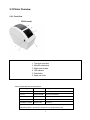
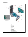
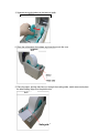
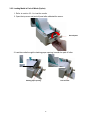
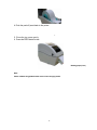
1
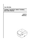
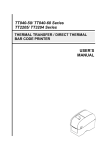
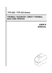
ZG352 DIRECT THERMAL BAR CODE PRINTER USER S MANUAL ’ Contents Copyright Declaration 1. Introduction ii 1.1 Product Introduction 1.2 Compliances 2. Operations Overview ii ii 5 1 2.1 Unpacking and Inspection 1 2.2 Printer Overview .2 2 4 2.2.1 Front View 2.2.2 Interior View 2.2.3 Rear View 3. Setup 3.1 Setting Up the Printer 3.2 Loading the Media 3.2.1 Loading the Media 3.2.2 Loading External Media 3.2.3 Loading Media in Peel-off Mode (Option) 3.2.4 Loading Media in Cutter Mode (Option) 3.3 Diagnostic Tool 3.3.1 Start the Diagnostic Tool 3.3.2 Printer Function (Calibrate sensor, Ethernet setup, RTC setup ) 3.4 Setting Ethernet by Diagnostic Utility 3.4.1 Using USB interface to setup Ethernet interface 3.4.2 Using Ethernet interface to setup Ethernet interface 3.5 Install MicroSD Memory Card 3.6 Mount the Printer on the Wall 4. LED and Button Functions 4.1 LED Indicator. 4.2 Regular Button Function 4.3 Power on Utilities . 4.3.1 Gap/Black Mark Sensor Calibration 4.3.2 Gap/Black Mark Calibration, Self-test and Dump Mode 4.3.3 Printer Initialization i 6 8 .8 .8 8 12 14 16 18 18 19 20 20 21 . 23 . 25 27 . 27 . 27 . 27 28 28 31 4.3.4 Set Black Mark Sensor as Media Sensor and Calibrate the Black 32 Mark Sensor 4.3.5 Set Gap Sensor as Media Sensor and Calibrate the Gap Sensor 32 32 4.3.6 Skip AUTO.BAS 5. Troubleshooting 34 34 5.1 LED Status 5.2 Print Problem 5.3 LCD 6. Maintenance 35 36 37 Revise History 39 ii i 1. Introduction 1.1 Product Introduction Thank you for purchasing a ZG352 bar code printer. Although the printer has a small footprint, it delivers reliable, superior performance. This printer provides direct thermal printing at user selectable speed of: 2.0, 3.0, 4.0 or 5.0 ips. It accepts roll feed, die-cut, and fan-fold media with gap or black mark. All common bar d formats are available. Fonts and bar codes can be printed in 4 directions, 8 different alphanumeric bitmap fonts and built-in scalable font capability. You will enjoy trouble free, high throughput for printing labels with this printer. 1.2 Compliances CE Class B: EN55022: 1998+A1: 2000+A2: 2003 EN55024: 1998+A1: 2001 +A2: 2003 IEC 61 000-4 Series EN61 000-3-2: 2006 & EN61 000-3-3: 1 995+A1: 2001 FCC Part 15, Class B UL, CUL: UL60950-1 C-Tick: CFR 47, Part 15/CISPR 22 3rdEdition: 1997, Class B ANSI C63.4: 2003 Canadian ICES-003 TÜV/Safety: EN60950-1 / IEC 60950-1 Wichtige Sicherheits-Hinweise 1. Bitte lesen Sie diese Hinweis sorgfältig durch. 2. Heben Sie diese Anleitung fűr den späteren Gebrauch auf. 3. Vor jedem Reinigen ist das Gerät vom Stromentz zu trennen. Verwenden Sie keine Flüssig-oder Aerosolreiniger. Am besten eignet sich ein angefeuchtetes Tuch zur Reinigung. 4. Die Netzanschluß-Steckdose soll nahe dem Gerät angebracht und leicht zugänglich sein. 5. Das Gerät ist vor Feuchtigkeit zu schűtzen. 6. Bei der Aufstellung des Gerätes ist auf sicheren Stand zu achten. Ein Kippen oder Fallen könnte Beschädigungen hervorrufen. 7. Beachten Sie beim Anschluß ans Stromnetz die Anschlußwerte. 8. Dieses Gerät kann bis zu einer Außentemperatur von maximal 40 betrieben d CAUTION 1. HAZARDOUS MOVING PARTS IN CUTTER MODULE. KEEP FINGER AND OTHER BODY PARTS AWAY. 2. THE MAIN BOARD INCLUDES REAL TIME CLOCK FEATURE HAS LITHIUM BATTERY CR2032 INSTALLED. RISK OF EXPLOSION IF BATTERY IS REPLACED BY AN INCORRECT TYPE. 3. DISPOSE OF USED BATTERIES ACCORDING TO THE MANUFACTURER INSTRUCTIONS. ii "ORSICHT" Explosionsgetahr bei unsachgemen Austausch der Batterie. Ersatz nur durch denselben oder einem vom Hersteller empfohlenem nlichen Typ. Entsorgung gebrauchter Batteries nach Angaben des Herstellers. WARNUNG! GEFÄHRLICHE BEWEGLICHE TEILE FINGER UND ANDERE KÖRPERTEILE FERNHALTEN! — VORSICHT! EXPLOSIONSGEFAHR BEI ERSATZ DER BATTERIE DURCH UNZULÄSSIGEN TYP. VERBRAUCHTE BATTERIEN IMMER VORSCHRIFTSGEMÄSS ENTSORGEN! Note The maximum printing ratio per dot line is 15% for this printer. To print the full web black line, the maximum black line height is limited to 40 dots, which is 5mm for 203 DPI resolution printer. B 81717 (1-714 1 JA-0.117 17) 171171=-21-714으-T전자파적합등록을한7171T-A1 1---7-11qlIA1=-21 C 1 L ~qlIA1₩}/4 ~수 있습니ry. 0 iii 2. Operations Overview 2.1 Unpacking and Inspection This printer has been specially packaged to withstand damage during shipping. Please carefully inspect the packaging and printer upon receiving the bar code printer. Please retain the packaging materials in case you need to reship the printer. Unpacking the printer, the following items are included in the carton. One printer unit One Windows labeling software/Windows driver CD disk One quick installation guide One power cord One auto switching power supply One USB interface cable One How to create a Logo Manual If any parts are missing, please contact the Customer Service Department of your purchased reseller or distributor. 2.2 Printer Overview 2.2.1 Front View ZG352 model 1. Top cover open lever 2. MicroSD card socket 3. Media view window 4. LED indicator 5. Feed button 6. Paper exit chute * Recommended MicroSD card specification. SD card spec SD card capacity Approved SD card manufacturer V1.0, V1.1 MicroSD 128 MB Transcend, Panasonic V1.0, V1.1 MicroSD 256 MB Transcend, Panasonic V1.0, V1.1 MicroSD 512 MB Transcend, Panasonic V1.0, V1.1 MicroSD 1 GB Transcend, Panasonic V2.0 SDHC CLASS 6 MicroSD 4 GB Transcend - The DOS FAT file system is supported for the SD card. - Folders/files stored in the SD card should be in the 8.3 filename format 2 3 2.2.2 Interior View 1 9 7 2 (ZG352 Model) 3 8 1. Top cover 2. Media holder 3. Media guide 4. Printhead 5. Gap sensor (receiver) 6. Gap sensor (transmitter) 7. Platen roller 8. Black mark sensor 9. Media holder lock switch 4 5 2.2.3 Rear View ZG352 model 4 1 2 3 1. Power switch 2. Power jack socket 3. USB interface 4. Fan-fold paper entrance chute Note: The interface picture here is for reference only. Please refer to the product specification for the interfaces availability. 6 7 3. Setup 3.1 Setting Up the Printer 1. Place the printer on a flat, secure surface. 2. Make sure the power switch is set to “off”. 3. Connect the printer to the computer with the provided USB cable. 4. Plug the power cord into the AC power cord socket at the rear of the printer, and then plug the power cord into a properly grounded power outlet. Note: Please switch OFF printer power switch prior to plug in the power cord to printer power jack. 3.2 Loading the Media 3.2.1 Loading the Media 1. Open the printer top cover by pulling the tabs located on each side towards the front of the printer, and then lift the top cover to the maximum open angle. 2. The media holder can be used for 1” and 1.5” media core by rotating the upper part of label holder 180 degrees clockwise. 1.5” 8 3. Separate the media holders to the label roll width. ZG352 model 4. Place the roll between the holders and close them onto the core. ZG352 5. Place the paper, printing side face up, through the media guides, media sensor and place the label leading edge onto the platen roller. ZG352 9 6. Close the top cover gently and make sure the cover latches securely. ZG352 model 7. Use “Diagnostic Tool” to set the media sensor type and calibrate the selected sensor. (Start the “Diagnostic tool” Select the “Printer Configuration” tab Click the “Calibrate Sensor” button) Note: Please calibrate the gap/black mark sensor when changing media. 10 • Loading path for roll labels ZG352 model 11 3.2.2 Loading External Media 1. Open the printer’s top cover and separate the media holders to fit the media width. 2. Press down the media holder lock switch to fix the media holder. 3. Feeds the media through the rear external label entrance chute. And place the paper, printing side face up, through the media guides, media sensor and place the label leading edge onto the platen roller. Rear external label entrance 4. Close the top cover gently. 5. Use “Diagnostic Tool” to set the media sensor type and calibrate the selected (Start the “Diagnostic tool” Select the “Printer Configuration” tab Sensor” button) Note: Please calibrate the gap/black mark sensor when changing media. 12 Click the “Calibrate Calibrate 13 3.2.3 Loading Media in Peel-off Mode (Option) 1. Refer to section 3.2.1 to load the media. 2. Open the top cover and peel-off panel after calibrated the sensor. Peel-off panel 3. Lead the media through the backing paper opening, beneath the peel-off roller. Backing paper opening Peel-off roller 14 4. Push the peel-off panel back to the printer. 5. Close the top cover gently. 6. Press the FEED button to test. Backing paper (Liner) Note: Please calibrate the gap/black mark sensor when changing media. 15 3.2.4 Loading Media in Cutter Mode (Option) 1. Refer to section 3.2.1 to load the media. 2. Lead the media through the cutter paper opening. Cutter paper opening 3. Close the top cover gently. 4. Use “Diagnostic Tool” to set the media sensor type and calibrate the selected sensor. (Start the “Diagnostic tool” Sensor” button) Select the “Printer Configuration” tab 16 Click the “Calibrate Note: Please calibrate the gap/black mark sensor when changing media. 17 3.3 Diagnostic Tool The Diagnostic Utility is enclosed in the CD disk \Utilities directory from. The Diagnostic Utility is a toolbox that allows users to explore the printer's settings and status; change printer settings; download graphics, fonts, and firmware; create printer bitmap fonts; and to send additional commands to the printer. Using this convenient tool, you can explore the printer status and settings and troubleshoot the printer. Note: This utility works with printer firmware V6.00 and later versions. 3.3.1 Start the Diagnostic Tool to start the software. 1. Double click on the Diagnostic tool icon 2. There are four features (Printer Configuration, File Manager, Bitmap Font Manager, Command Tool) included in the Diagnostic utility. Features tab Interface Printer functions Printer setup Printer Status 18 3.3.2 Printer Function (Calibrate sensor, Ethernet setup, RTC setup ) 1. Select the PC interface connected with bar code printer. 2. Click the “Function” button to setting. 3. The detail functions in the Printer Function Group are listed as below. Function Calibrate Sensor Ethernet Setup Description Calibrate the sensor specified in the Printer Setup group media sensor field Setup the IP address, subnet mask, gateway for the on board Ethernet (Please refer to next section) RTC Time Synchronize printer Real Time Clock with PC Print Test Page Print a test page Reset Printer Reboot printer Factory Default Initialize the printer and restore the settings to factory default. Dump Text To activate the printer dump mode. Ignore AUTO.BAS Ignore the downloaded AUTO.BAS program Configuration Page Print printer configuration Note: For more information about Diagnostic Tool, please refer to the diagnostic utility quick start guide in the CD disk \ Utilities directory. 19 3.4 Setting Ethernet by Diagnostic Utility The Diagnostic Utility is enclosed in the CD disk \Utilities directory . Users can use Diagnostic Tool to setup the Ethernet by USB and Ethernet interfaces. The following contents will instruct users how to configure the Ethernet by these interfaces. 3.4.1 Using USB interface to setup Ethernet interface 1. Connect the USB cable between the computer and the printer. 2. Turn on the printer power. icon. 3. Start the Diagnostic Utility by double clicking on Note: This utility works with printer firmware V6.00 and later versions. 4. The Diagnostic Utility default interface setting is USB interface. If USB interface is connected with printer, no other settings need to be changed in the interface field. 5. Click on the Ethernet Setup button from Printer Function group in Printer Configuration tab to setup the IP address, subnet mask and gateway for the on board Ethernet. “ ” “ 20 ” 3.4.2 Using Ethernet interface to setup Ethernet interface 1. Connect the computer and the printer to the LAN. 2. Turn on the printer power. icon. 3. Start the Diagnostic Utility by double clicks on the Note: This utility works with printer firmware V6.00 and later versions. 4. Select Ethernet as the interface then click on the Setup button to setup the IP address, subnet mask and gateway for the on board Ethernet. “ ” “ ” 5. Click the Discover Device button to explore the printers that exist on the network. “ ” 6. Select the printer in the left side of listed printers, the correspondent IP address will be shown in the right side IP address/Printer Name field. 7. Click Change IP Address to configure the IP address obtained by DHCP or static. “ “ ” ” The default IP address is obtained by DHCP. To change the setting to static IP address, click Static IP radio button then enter the IP address, subnet mask and gateway. Click “ ” 21 Set IP to take effect the settings. “ ” Users can also change the Printer Name by another model name in this fields then click Set Printer Name to take effect this change. Note: After clicking the Set Printer Name or Set IP button, printer will reset to “ “ ” ” “ ” “ ” take effect the settings. 8. Click Exit button to exit the Ethernet interface setup and go back to Diagnostic Tool main screen. “ ” Factory Default button This function will reset the IP, subnet mask, gateway parameters obtained by DHCP and reset the printer name. Web setup button Except to use the Diagnostic Utility to setup the printer, you can also explore d configure the printer settings and status or update the firmware with the IE or Firefox web browser. This feature provides a user friendly setup interface and the capability to manage the printer remotely over a network. 22 3.5 Install MicroSD Memory Card 1. Open the SD memory card cover. 2. Insert the MicroSD card into the socket. 3. Close the memory card cover. * Recommended SD card specification. SD card spec SD card capacity Approved SD card manufacturer V1.0, V1.1 MicroSD 128 MB Transcend, Panasonic V1.0, V1.1 MicroSD 256 MB Transcend, Panasonic V1.0, V1.1 MicroSD 512 MB Transcend, Panasonic V1.0, V1.1 MicroSD 1 GB Transcend, Panasonic V2.0 SDHC CLASS 6 MicroSD 4 GB Transcend - The DOS FAT file system is supported for the SD card. 23 - Folders/files stored in the SD card should be in the 8.3 filename format 24 3.6 Mount the Printer on the Wall There are three holes in the bottom of printer. Printer can be mounted on the wall by the 3.0mm~3.5mm screw head screws. Note: Please hang properly to avoid fall down 25 26 4. LED and Button Functions This printer has one button and one three-color LED indicator. By indicating the LED with different color and pressing the button, printer can feed labels, pause the printing job, select and calibrate the media sensor, print printer self-test report, reset printer to defaults (initialization). Please refer to the button operation below for different functions. 4.1 LED Indicator LED Color Green/ Solid Description This illuminates that the power is on and the device is ready to use. Green/ Flash Amber Red / Solid This illuminates that the system is downloading data from PC to memory or the printer is paused. This illuminates that the system is clearing data from printer. This illuminates printer head open, cutter error. This illuminates a printing error, such as head open, paper Red / Flash empty, paper jam or memory error etc. 4.2 Regular Button Function 1. Feed labels When the printer is ready, press the button to feed one label to the beginning of next label. 2. Pause the printing job When the printer is printing, press the button to pause a printing job. When the printer is paused, the LED will be green blinking. Press the button again to continue the printing job. 4.3 Power on Utilities There are six power-on utilities to set up and test printer hardware. These utilities are activated by pressing FEED button then turning on the printer power simultaneously and release the button at different color of LED. Please follow the steps below for different power-on utilities. 1. Turn off the power switch. 2. Hold on the button then turn on the power switch. 3. Release the button when LED indicates with different color for different functions. 27 Power on utilities The LED color will be changed as following pattern: Amber LED color Red Amber Green Green/Amber Red/Amber Solid green Functions (5 blinks) (5 blinks) (5 blinks) 1. Gap / black mark sensor calibration Release 2. Gap / black mark sensor calibration, (5 blinks) (5 blinks) Release Self-test and enter dump mode 3. Printer initialization Release 4. Set black mark sensor as media Release sensor and calibrate the black mark sensor 5. Set gap sensor as media sensor and Release calibrate the gap sensor 6. Skip AUTO.BAS Release 4.3.1 Gap/Black Mark Sensor Calibration Gap/black mark sensor sensitivity should be calibrated at the following conditions: 1. A brand new printer 2. Change label stock. 3. Printer initialization. Please follow the steps below to calibrate the gap/black mark sensor. 1. Turn off the power switch. 2. Hold on the button then turn on the power switch. 3 Release the button when LED becomes red and blinking. (Any red will do during the 5 blinks). It will calibrate the gap/black mark sensor sensitivity. The LED color will be changed as following order Amber red (5 red/amber (5 blinks) amber (5 blinks) solid green green (5 blinks) green/amber (5 blinks) Note: 1. Sensor calibration can be done by Diagnostic Tool or by power on utility. Please refer to 3.3 “ Diagnostic Tool Section for more information. ” 2. Please select gap or black mark sensor type prior to calibrate the sensor. 28 4.3.2 Gap/Black Mark Calibration, Self-test and Dump Mode While calibrate the gap/black mark sensor, printer will measure the label length, print the internal configuration (self-test) on label and then enter the dump mode. To calibrate gap or black mark sensor, depends on the sensor setting in the last print job. Please follow the steps below to calibrate the sensor. 1 .Turn off the power switch. 2. Hold on the button then turn on the power switch. 3. Release the button when LED becomes amber and blinking. (Any amber will do during the 5 blinks) • The LED color will be changed as following order. green (5 blinks) amber (5 blinks) red (5 Amber solid green red/amber (5 blinks) green/amber (5 blinks) 4. It calibrates the sensor and measures the label length and prints internal settings then enter the dump mode. Note: 1. Sensor calibration can be done by Diagnostic Tool or by power on utility. Please refer to 3.3 “ Diagnostic Tool Section for more information. ” 2. Please select gap or black mark sensor type prior to calibrate the sensor. 29 Self-test Printer will print the printer configuration after gap/black mark sensor calibration. Self-test printout can be used to check if there is any dot damage on the heater element, printer configurations and available memory space. • Dump mode Printer will enter dump mode after printing printer configuration. In the dump mode, all characters will be printed in 2 columns as following. The left side characters are received from your system and right side data are the corresponding hexadecimal value of the characters. It allows users or engineers to verify and debug the program. 30 Hex decimal data related to left column of ASCII data ASCII Data Note: 1. Dump mode requires 2” wide paper width. 2. Turn off / on the power to resume printer for normal printing. 3. Press FEED button to back to the previous menu. 4.3.3 Printer Initialization Printer initialization is used to clear DRAM and restore printer settings to defaults. Printer initialization is activated by the following procedures. 1. Turn off the power switch. 2. Hold on the button then turn on the power switch. 3. Release the button when LED turns green after 5 amber blinks. (Any green will do during the 5 blinks). • The LED color will be changed as following: amber (5 blinks) solid green Amber red (5 red/amber (5 blinks) green (5 blinks) green/amber (5 blinks) Printer configuration will be restore to defaults as below after initialization. Parameter Default setting Speed 127 mm/sec (5 ips) (203DPI) Density 8 Label Width 2” (50.8 mm) Label Height 4” (101.6 mm) Sensor Type Gap sensor Gap Setting 0.12” (3.0 mm) 31 Print Direction 0 Reference Point 0,0 (upper left corner) Offset 0 Tear Mode On Peel off Mode Off Cutter Mode Off Serial Port Settings 9600 bps, none parity, 8 data bits, 1 stop bit Code Page 850 Country Code 001 Clear Flash Memory No IP Address DHCP 4.3.4 Set Black Mark Sensor as Media Sensor and Calibrate the Black Mark Sensor Please follow the steps as below. 1. Turn off the power switch. 2. Hold on the button then turn on the power switch. 3. Release the button when LED turns green/amber after 5 green blinks. (Any green/amber will do during the 5 blinks). The LED color will be changed as following: red (5 Amber red/amber (5 blinks) amber (5 blinks) solid green green (5 blinks) green/amber (5 blinks) 4.3.5 Set Gap Sensor as Media Sensor and Calibrate the Gap Sensor Please follow the steps as below. 1. Turn off the power switch. 2. Hold on the button then turn on the power switch. 3. Release the button when LED turns red/amber after 5 green/amber blinks. (Any red/amber will do during the 5 blinks). The LED color will be changed as following: Amber red (5 blinks) red/amber (5 blinks) amber (5 blinks) solid green green (5 blinks) green/amber (5 blinks) 4.3.6 Skip AUTO.BAS TSPL2 programming language allows user to download an auto execution file to flash memory. Printer will run the AUTO.BAS program immediately when turning on printer power. 32 The AUTO.BAS program can be interrupted without running the program by the power-on utility. Please follow the procedures below to skip an AUTO.BAS program. 1. Turn off printer power. 2. Press the FEED button and then turn on power. 3. Release the FEED button when LED becomes solid green. The LED color will be changed as following: • green (5 blinks) Amber red (5 blinks) amber (5 blinks) solid green red/amber (5 blinks) 4. Printer will be interrupted to run the AUTO.BAS program. 33 green/amber (5 blinks) 5. Troubleshooting The following guide lists the most common problems that may be encountered when operating this bar code printer. If the printer still does not function after all suggested solutions have been invoked, please contact the Customer Service Department of your purchased reseller or distributor for assistance. 5.1 LED Status This section lists the common problems that according to the LED status and other problems you may encounter when operating the printer. Also, it provides solutions. LED Status Printer / Color Status OFF No response Possible Cause No power Recovery Procedure * Turn on the power switch. * Check if the green LED is lit on power supply. If it is not lit on, power supply is broken. * Check both power connections from the power cord to the power supply and from the power supply to the printer power jack if they are connected securely. Solid Green ON The printer is ready to * No action necessary. use Green with Pause The printer is paused * Press the FEED button to resume for printing. blinking Red with blinking Error The out of label or the 1. Out of label printer setting is not * Load a roll of label and follow the instructions in loading the media then press the FEED button to correct resume for printing. 2. Printer setting is not correct * Initialize the printer by instructions in “Power on Utility” or “Diagnostic Tool”. Note: Printer status can be easily shown on the Diagnostic Tool. For more information about the Diagnostic Tool, please refer to the instruction in the software CD disk. 34 5.2 Print Problem Problem Possible Cause Check if interface cable is well Recovery Procedure Re-connect cable to interface. connected to the interface connector. Not Printing The serial port cable pin configuration is Please replace the cable with pin to pin not pin to pin connected. connected. The serial port setting is not consistent Please reset the serial port setting. between host and printer. The port specified in the Windows driver Select the correct printer port in the is not correct. driver. The Ethernet IP, subnet mask, gateway Configure the IP, subnet mask and is not configured properly. gateway. Follow the instructions in loading the No print on the label Label loaded not correctly. Continuous feeding labels media. The printer setting may go wrong. Gap/black mark sensor sensitivity is not Please do the initialization and gap/black mark calibration. Calibrate the gap/black mark sensor. set properly (sensor sensitivity is not enough) Paper Jam Make sure label size is set properly. Set label size exactly as installed paper in the labeling software or program. Labels may be stuck inside the printer Remove the stuck label. mechanism near the sensor area. Top cover is not closed properly. Wrong power supply is connected with printer. Check if supply is loaded correctly. Poor Print Quality Check if dust or adhesives are Close the top cover completely and make sure the right side and left side levers are latched properly. Check if 24V DC output is supplied by the power supply. Reload the supply. Clean the print head. accumulated on the print head. Check if print density is set properly. Check print head test pattern if head element is damaged. 35 Adjust the print density and print speed. Run printer self-test and check the print head test pattern if there is dot missing in the pattern. 5.3 LCD display This section lists the LCD display messages that you may encounter when operating the printer. Also, it provides solutions. Messages Possible Cause No Paper Paper Jam Out of Mem Recovery Procedure * The printer top cover is open. * Please close the top cover. * Running out of label. * The label is installed incorrectly. * Gap/black mark sensor is not calibrated. * Supply a new label roll. * Please refer to the steps in user’s manual to reinstall the label roll. * Calibrate the gap/black mark sensor. * Gap/black mark sensor is not set properly. * Make sure label size is set properly. * Labels may be stuck inside the printer mechanism. Cutter Error * Calibrate the gap/black mark sensor. * Set label size correctly. * The space of FLASH/DRAM or MicroSD card is full. * Delete unused files in the FLASH/DRAM or MicroSD card. * Peel function is enabled. Waiting user to take label away to print the next label. * Please take the label away to print the next label if peeler module is installed. * If peeler module is installed and label is been taken away, but the message remains. Please check if the peeler module connector is connected to main board properly. * If peeler module is not installed, please disable the peeler function. Take Label * Cutter jam. * There is no cutter installed on the printer. * Cutter or cutter driver circuit board is damaged. 36 Head Open * Remove the jammed label. * Make sure the media thickness is equal or less than 0.19mm. * Replace the cutter or cutter driver circuit board. 6. Maintenance This session presents the clean tools and methods to maintain your printer. 1. Please use one of following material to clean the printer. Cotton swab (Head cleaner pen) Lint-free cloth Vacuum / Blower brush 100% ethanol 2. The cleaning process is described as following: Printer Part 1. Always turn off the printer before cleaning Clean the print head when changing a Method Interval new label roll the print head. 2. Allow the print head to cool for a minimum of one minute. 3. Use a cotton swab and 100% ethanol to clean the print head surface. Print Head 1. Turn the power off. 2. Rotate the platen roller and wipe it Platen Roller thoroughly with 100% ethanol and a cotton swab, or lint-free cloth. Use the lint-free cloth with 100% ethanol to Tear Bar/Peel Bar Clean the platen roller when changing a new label roll As needed wipe it. Sensor Compressed air or vacuum Monthly Exterior Wipe it with water-dampened cloth As needed Interior Brush or vacuum As needed Note: Do not touch printer head by hand. If you touch it careless, please use ethanol to clean it. 37 • Please use 100% Ethenol. DO NOT use medical alcohol, which may damage the printer head. Regularly clean the print head and supply sensors once change a new media to keep printer performance and extend printer life. The maximum printing ratio per dot line is 15% for this printer. To print the full web black line, the maximum black line height is limited to 40 dots, which is 5mm for 203 DPI resolution printer. 38 Revise History Date Content Editor 2009/8/10 Revise 2.2.2 section Camille 2009/9/7 Revise 3.3 Diagnostic Tool section Camille 2009/9/15 Add TDP-225W model Camille 2009/9/16 Add 3.4 section Camille 2009/9/18 Add 5.3 section Camille 2009/12/28 Revise 2.2.3 section (Add USB host) Camille Revise 1.2 section Camille *Add 3.7 section (Using the keyboard with USC host interface) Camille 2010/3/3 2010/3/12 *Revise 3.1 & 2.2.3 sections 2010/11/23 Revise 1.2 and 2.2.3 section Camille 2011/1/25 Modify TSC address Camille 39 Avery Weigh-Tronix USA 1000 Armstrong Dr. Fairmont MN 56031 USA Tel: 507-238-4461 FAX: 507-238-4195 Web site: www.wtxweb.com E-mail: [email protected] Avery Weigh-Tronix UK Foundry Lane Smethwick, West Midlands England B66 2LP Tel: +44(0)8453 66 77 88 Fax: 44(0)121 224 8183 Email: [email protected] www.averyweigh-tronix.com 10/12 ZG352_u_en_501060.pdf AWT35-501060