1
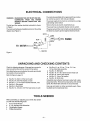
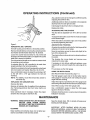
SAVE THIS MANUAL
FOR
FUTURE REFERENCE
OWNER'S
MANUAL
MODEL NO.
351.226712
/£RRFrSHRN®
l x 6" Belt & Disc Sander
CAUTION:
READ ALL
INSTRUCTIONS
CAREFULLY!
• safety instructions
= operating instructions
• replacement parts
Sold by SEARS, ROEBUCK
Part No. 3899.01
AND CO., Chicago,
IL 60684
U.S.A. ©
AUGUST
1993
FULL ONE YEAR WARRANTY ON SEARS/CRAFTSMAN
1 x 6" BELT & DISC SANDER
if within one full year from tile date of purchase, this Sears Craftsman
defect in material or workmanship, Sears will repair it, free of charge.
1 x 6" Belt & Disc Sander fails due to a
WARRANTY SERVICE iS AVAILABLE BY SIMPLY CONTACTING THE NEAREST SEARS STORE OR SERVICE
CENTER THROUGHOUT THE UNITED STATES.
This warranty gives you specific legal rights, and you may have other rights whictl vary from state to state,
SEARS, ROEBUCK AND CO., D817/WA, HOFFMAN ESTATES, IL 60179
GENERAL
SAFETY
INSTRUCTIONS
BEFORE ANY WORK IS DONE READ THE CAUTIONS
LISTED BELOW CAREFULLY, WORKING SAFELY
PREVENTS ACCIDENTS,
e+
f+
Keep all guards in place and in working order.
Keep all parts in working order. Check to determine that the guard or other parts will operate
propedy and perform their' intended function+
g
Check for damaged parts+ Check for atignment of
moving parts, binding of moving parts, breakage of
parts, mounting and any other condition that may
affect a tool's operation
h+ A guard or other part that is damaged should be
properly repaired or replaced. Do not perform
makeshift repairs_ (Use the parts list provided to
+
order replacement parts+)
OPERATOR SHOULD BE PREPARED FOR JOB:
a+
Wear proper apparel+ Do not wear loose clothing,
gloves, neckties, rings, bracelets or other jewelry
which may get caught in moving parts of machine
b. Wear protective hair covering to contain long hair.
c
Wear safety shoeswith non-slip soles+
d.. Wear safety glasses+ Everyday glasses have only
impact resistant lenses+They are not safety glasses
e. Wear face mask or dust mask if sanding operation
is dusty+
f
Be alert and think clearly. Never operate power
tools when tired, intoxicated or when taking medications that cause drowsiness.
OPERATOR SHOULD KNOW HOW TO USE TOOL:
a+
Use right tool for the job. Do not force tool or'
attachment to do a job for which it was not de+
signed.
b. Disconnect tool when changing accessories,
such as belt, disc, miter gauge and the like.
c
Avoid accidental start-up. Make sure that the
machine is in the "off" position before plugging in+
d° Do not force a tool It will work most efficiently at
the rate for which it was designed
e+ Use recommended accessories, Referto page 11.
Use of improper accessories may cause risk of injury
to persons
WORK AREA SHOULD BE READY FOR JOB:
a+
Keep work area clean+ Cluttered work areas and
workbenches invite accidents,,
b+ Do not use power tools in dangerous environmerits+ Do not use power' tools in damp or. wet
locations. Do not expose power tools to rain.
c+ Work area should be properly lighted.
d+ Proper electrical outlet should beavailablefortooL
Three-prong plug should be plugged directly into
properly grounded, three-prong receptacle+
e+ Extension cords should have a grounding prong
and the three wires of the extension cord should be
the correct gauge+
f+ Keep visitors a safe distance from work area+
g+ Keep children out of workplace+ Make workshop
child-proof. Use padlocks, master' switches and
remove starter' keys to prevent any unintentional use
of power tools,
f+
g+
c+
d.
Handle the workpiece correctly. Use m_ter gauge
when required, Protect hands from possibleinjury+
Direction of feed. Feed work into a belt or disc
against direction of rotation of the belt or+disc.
h+ Turn the machine off if it jams. Disconnect plug
from power' source before servicing tool.,
L
Never leave a tool running unattended+ Turn the
power off and do not leave sander until it comes to
a complete stop+
j+ Do not overreach.
Keep proper footing and
balance,
TOOL SHOULD BE MAINTAINED:
a+
b+
FOR POWER TOOLS
Always unplug power tool prior, to inspection.
Consult owner's manual for specific maintainirlg
and adjusting pr.ocedureso
Use clean belts and keep the tool clean for safest
operation+
Remove adjusting keys and wrenches. Form
habit of checking to see that keys and adjusting
wrenches are removed before turning tool on.
k+
Never stand on tool Serious injury could occur if
tool is tipped or' if abrasive belt or disc is unintentionally contacted+
I+
Keep hands away from moving parts and sanding
surfaces+
m+ Know your power tool. Learn itsoperation, application and specific limitations+
-2-
CONTENTS
Warranty ................................
General Safety Instructions
for Power Tools ......................
2
Unpacking and Checking Contents ...........
Tools Needed ............................
Assembly ...............................
Operation ...............................
Maintenance ..........................
Trouble Shooting .........................
Replacement Parts Illustration ..............
Replacement Parts List ....................
2
Safety Instructions
for Belt & Disc Sander .................
Motor Specifications
and Electrical Requirements
............
Electrical Connections
..................
3
4
4& 5
WARNING
5
5
6
6
8 &9
9
10
11
LABEL
This warning label is placed in a specific location so it is
visible to the operator when starting and operating the
belt and disc sander.
The belt and disc sander has been marked with a warning
label that needs to be observed for safe operation. The
operator should be aware of the location and contents
of thts label
WARNING
FOR SAFE OPERATION SEE OWNER'S MANUAL
1_
Always wear safety gog_le_ complying with ANSI Z871
II
When soMctng
M
Suppottwo;kplecewIlhbacksloporwoTklable
H
Maintain
Im
Mount
1116" max
securely
SAFETY INSTRUCTIONS
WARNING:
use anty Identlca, I replacement
clearance
beM, een table and sanding belt ot d_ec
to workbench
FOR l"x
DO NOT ATTEMPT TO OPERATE BELT
& DISC SANDER UNTIL IT IS COMPLETELY ASSEMBLED ACCORDING
TO THE INSTRUCTIONS.
t
Know general power tool safety, Make sure all
precautions are understood and provlded for (page
2.
Secure all fasteners. Frequently check that nuts
and bolts are tight and have not vibrated loose,
3.
Follow operation instructions.
Operate the belt
and disc sander as described in this manual (pages
6 through 8).
4,,
Be sure motor runs clockwise
Abrasive belt must travel down
,,
,
8_
9,
6" BELT & DISC SANDER
10o
Do not grind or polish magnesium.
on fire.
11_
Keep sander maintained. Follow "Maintenance
instructions" (page 9).
12
Disconnect power, Turn :switch off and disconnect
power whenever sander is not in use.
CAUTION:
on disc side.
It could catch
Be certain to follow proper operating
procedures despite familiarity gained
from frequent use of your belt and disc
sander. Always remember that being
careless for even a fraction of a second
is sufficient time to inflict severe injury.
The operation of any power tool can result In foreign
objects being thrown into the eyes, which can result in
severe eye damage,
Perform disc sanding on down side (right side).
The disc should pull work towards the table°
Always wear safety goggles complying with ANSI Z87ot
(shown on package) before commencing power tool
operation° Safety goggles are available at Sears retail or
catalog stores.
Support workpiece. Use backstop or work table
The backstop for the abrasive belt is the belt platen
(Key No. 25) as described in "Operating Instructions" (page 7),,
6_
pads
THINK SAFETY: Safety is a combination of operator
common sense and alertness at alt
times when the belt & disc sander is
being used_
Do not force work° Slowing or stalling the motor
will overheat it,
Do not overheat work. Move metal across the
abrasive and cool it when it becomes hot.
Do not wet grind or polish. Never use a steady
stream of water on the workpieceo Only quench the
workpiece in water to cool it.
-3-
MOTOR SPECIFICATIONS
AND ELECTRICAL REQUIREMENTS
PROPERLY
GROUNDED
MOTOR
The belt and disc sander is assembled with motor and
wiring insta!led as an integral part of the tool..
OUTLET
The 120 Volt AC permanent split capacitor motor' has the
following specifications:
Max..Developed Horsepower ......................
1/2
Voltage .................................................
120
Amperes ..............................................
4
Hertz ..............................................
60
Phase ...........................................
Single
RPM ..........................................
3450
Rotation(viewedfrom left
side)..........Clockwise
POWER SOURCE
CAUTION:
1.
2_
3.
4.
""
PRONG
"_
This toot is intended for' use on a circuit having a nominal
rating tess than I50 volts which has an outlet that looks
tike the one illustrated above.
A temporary adapter', which looks like outlet illustrated
below, may be used to connect this plug to a two-pole
receptacle if a properly grounded outlet is not available.
The temporary adapter should be used only until a
properly grounded outlet can be installed by a qualified
electrician,
Do not connect the belt and disc sander
to the power source until all assembly
steps have been completedo
The green colored grounding lug extending from the
adapter must be connected to a permanent ground such
as a properly grounded outlet box.
The motor is designed for operation on the voltage
and frequency specified on motor nameptatev
Normal loads will be handled safely on voltages not
more than 10% above or below nameplate voltage.
Running the unit on voltages which are not within
range may cause overheating and motor- burn-ouL
Heavy loads require that voltage at motor terminals
be not less than voltage specified on nameplate.
Make
sure
adapter
ts
connectedto a known
grounded receptacle
ADAPTER
3-PRONG PLUG_
GROUNDING INSTRUCTIONS
This tool is equipped with a 3-conductor cord and
ground type plug which has a grounding prong approved by Underwriters Laboratories and the Canadian
Standards Association.
NOTE: The adapter illustrated is for use onIy if you
already have a properly grounded 2-prong
receptacle. Adapter ts not allowed in Canada by
the Canadian Electrical Code.
Do not remove or' alter' the grounding prong in any
manner° In the event of a malfunction or breakdown,
grounding provides a path of least resistance for electrical current to reduce the risk of electrical shock
EXTENSION CORDS
1_ The use of any extension cord wilt cause some drop
in the voltage and loss of power.
2. Wires of extension cord must be sufficient in size to
The plug must be plugged into a matching outlet that is
properly installed and grounded in accordance with all
local codes and ordinances,.
carry current and maintain adequate voltage
Use the table below to determine the minimum wire
size (A.W.G) extension cord°
4. Use only 3-wire extension cords which have 3prong grounding type plugs and 3-pole receptacles
which accept the tool plug.
5. If power cord is worn, cut or damaged in any way,
have it replaced immediately.
Extension cord length
Wire Size A.W.Go
Upto 100ft .........................................
16
NOTE: Using extensioncords over'100 ft.,
long isnot
recommended°
Do not modify the plug provided° If it will not fit In the
outlet, have the proper' outlet installed by a qualified
electrictan_ improper connection of equipment-grounding conductor can result in a rlsk of electrical shock.
The conductor with insulation having an outer surface
which is green ts the equipment grounding conductor.
3,
If repair or replacement of the electrical cord or plug is
necessary, make sure the equipment grounding conductor is not connected to a line terminal.
WARNING:
"_
CHECK WITH A QUALIFIED ELECTRICIAN OR SERVICE PERSONNEL IF THE
GROUNDING INSTRUCTIONS ARE NOT
UNDERSTOOD OR IF IN DOUBT AS TO
WHETHER
TOOL
IS
PROPERLY
GROUNDED,
WARNING:
-4-
DO NOT PERMIT FINGERS TO TOUCH
THE TERMINALS OF PLUGS WHEN INSTALLING OR REMOVING THE PLUG
TO OR FROM OUTLET.
ELECTRICAL CONNECTIONS
WARNING;
The motor is assembled with an approved three conductor cord to be used on 120 volts as indicated,
MAKE SURE THE UNIT IS OFFAND DISCONNECTED
FROM
THE POWER
SOURCE BEFORE INSPECTING ANY
WIRING,
The power supply to the motor is controlled by a single
pole locking rocker switch.
Remove the key to prevent unauthorized use,.
The power lines are inserted directly onto the switch°
The belt and disc sander electrical schematic is shown
in Figure 1.
The motor and wiring are installed as shown in the wiring
diagram (see Figure 1)o
The green ground line must remain securely fastened to
the frame to properly protect against electrical shock.
$WETCH_
BLACK
TO POWER
BLACK
M
_
=
TO
CAPACITOR
Figure I
UNPACKING AND CHECKING
Check for shipping damages. If damage has occurred a
claim should be filed with the carrier for fast action.
Parts listed below are not attached to sander and should
be located and accounted for.
Refer to Figure 4, page 10,
•
e
e
e
e
e
Key No,. 13, 6mm-loO Hex nut, 2 each
Key Noo 54, 6mm Flat washer, 2 each
Key No. 11, 6-1o0 x 20ram Socket head bolt, 2 ea.
Key No. 5, Disc guard
Key No. 8, Dust chute
Key No. 12, #t0-24 x 1/2" Pan head screw, 2 each
TOOLS
While assembling or adjusting your belt & disc sander
you wil! need the following tools:
1. 8and lOmmWrench
2o 3, 4, 6, and 8ram Hex Wrenches
&
Combination Square
4o Phillips Screwdriver
CONTENTS
•
Key Nos. 4-1 ea., 6-2 ea. 7-2 ea., 54- 2 eao,
10-1 ea, Disc table assembly
• Key Nor 47, Belt table
e Key No. 49, 10-1_50 x 25mm Socket head bolt
• Key No. 50, lOmm Lockwasher
e Key No. 51, lOmm Flat washer
• Key No. 48, Work stop
Unpainted steel surfaces have been coated with a shipping preservative. Remove the preservative with mineral
spiritso Non-flammable solvents are recommended°
Use soap and water on rubber and plastic parts° Cleaning fluids tend to deteriorate them..
NEEDED
ASSEMBLY
CAUTION:
DO NOT ATTEMPT
ASSEMBLY IF
PARTS ARE MISSING. US_E OWNER'S
MANUAL TO ORDER REPLACEMENT
PARTS,
Be sure that the gap between the disc and disc table is
1/16" or'less. Secure guard and table position by tightening the socket head bolts and hex nuts (Key Nos. 11, 13
and 9).
Refer to Figure 4o
ASSEMBLE DISC TABLE
ASSEMBLE BELT TABLE
Mount disc table (Key Noo 4) to the disc guard (Key No.
5)_ Slide the pins located at the top, rear of the disc table
into the L-shaped slots on either side of the disc guard.
Sltde the 1/4-20 x 1" carriage bolts (Key No_ 6) into the
square holes on either' side of disc guard and through
the slots in the table, Secure the carriage bolts with
2 each-6mm flat washers and wing nuts (Key Noso
54 and 7)
Slide the disc guard over the 6" disc on the sander'
assembly. With the exhaust port tothe rear of the sander',
slide the dust chute (Key No. 8) onto the disc guard from
below the 6" disc. Be sure that the mounting on the disc
guard and the dust chute are aligned and secure the
assembly with 2 each pan head screws (Key Nov 12) and
2 each socket head bolts, washers and hex nuts (Key
Nos 11,54 and 13)_
Mount the belt table (Key No. 47) to the belt housing
using a socket head bolt, lock washer and fiat washer
(Key Nos. 49, 50 and 51). Be sure that the gap between
the belt table and belt is 1/16" or' less_ Tighten bolt
securely°
OPERATING
SAFETY PRECAUTIONS
WARNING:
ALWAYS OBSERVE THE FOLLOWING
SAFETY PRECAUTIONS°
Whenever adjusting or replacing any parts on the sander
turn switch OFF and remove the plug from power source.
Recheck table locking nuts and bolts_ They must be
tightened securely.
Make sure all guards are properly attached.. All guards
should be fastened securely.
Make sure all moving parts are free and clear of any
intefference_
The work stop (Key No. 48) can be used in place of the
table. Remove table and mount work stop with bolt and
washers. Be sure that the gap between the work stop
and belt is 1/16" or tess.
INSTRUCTIONS
Make sure abrasive belt always tracks properly_ Correct
tracking gives optimum performance.
After turning switch on, always allow the belt to come up
to full speed before sanding or' grinding.
Keep your' hands clear of abrasive belt, disc and all
moving parts.
For optimum performance do not stall motor' or reduce
belt speed. Do not force the work into the abrasive,
Never push a sharp corner of the workpiece
against the belt or disc° The abrasive may tear.
rapidly
With power disconnected, test operation by hand for
clearance and adjust if necessary_
Replace abrasives when they become loaded (glazed)
or frayed°
Always wear eye protection or face shield_
When grinding metal move the workpiece across the
abrasive to prevent heat build up.,
Never attempt wet cutting. If the wor kptece becomes too
hot to handle, cool it in cold water.
TENSIONING ABRASIVE BELT
Tension is created by a sprtng loaded cam shaft (Key Noo
57)_
The tracking wheel is mounted on the opposite side of
the shafL
"['he spring tension is transmitted to the tracking wheel
(Key No_ 56) and maintains the tension on belt
OPERATRNG UNSTRUCTIONS (Continued)
REPLACING ABRASIVE BELT
ABRASIVE BELT FINISHING
Remove belt table (Key No. 47) by removing socket head
bolt, lock washer and flat washer (Key Nos. 49, 50 & 51)_
The abrasive belt can be used to sand wood, deburr
Remove the belt guard (Key No_38) by removing thumb
knobs (Key No. 36)_
Release the tension on the belt by pulling the tension
handle (Key No. 65) forward (towards operator)°
Remove belt.. The abrasive belt may have an arrow
printed on the inside whlch indicates the direction of
travel,.
The belt is most efficient when used with the table, The
1" belt size is convenient for getting into corners and
concave curved edge&
metal, or polish plastic and glass,
ADJUSTING BELT PLATEN
Operating with the belt platen in place will allow the
operator to sand or grind stralght even lines,
The arrow should point down toward the belt table to
ensure that the splice in the belt will not come apart°
Pull on tension handle to install abrasive belt..
The platen should be adjusted so the belt does not ride
on the platen until work is fed into the belt,
Place the abrasive belt squarely on the wheels.
To adjust belt platen, loosen two each socket head bolts
(Key No. 53) and adjust. Tighten bolts securely.
The spring action will tension the beIL
Make sure the belt is tracking correctly. Adjust the tracking if necessary,.
When the belt is tracking properly tt rides on the center
of each wheel.
POLISHING AND CONTOUR SANDING
Replace the belt guard and belt table.
Remove platen (Key Non 52) by removing socket head
bolts and washers (Key Nos. 53 and 54),
TRACKING ABRASIVE
The belt is flexible (no rigid back) and is abte to follow
the contour of curved parts.
Test the tracking., Plug in power cord. Turn switch ON
and immediately OFF.
if the abrasive belt did not move to the right or left, it is
tracking properly.
If the belt moved to the right or left, adjustment is necessary_
Move the workpiece against beltoThe belt will follow the
contour (see Figure 2)_
To adjust the tracking wheel loosen the Iocknut (Key No_
66),
Use a 4mm hex wrench to turn the tracking adjusting bolt
(Key No_ 59)°
If the abrasive belt moves to the left, turn the adjusting
bolt counterclock"wtse.
Lock the position when the belt is tracking properly so
the belt will remain centered on the wheels°
Hold the position of the tracking adjustment screw with
the 4mm hex wrench.
Figure 2
Use a 8mm wrench to tighten locknut to lock positton_
SHARPENING
ADJUSTING BELT TABLE ANGLE
Adjust belt table to the desired sharpening angle and
tighten securely. Use the belt sander to notch the back
of an auxiliary piece of wood.
To adjust the angle of the belt table, loosen the socket
head bolt (Key No_ 49) and adjust to the desired angle,
Use a combination square to set the belt table at 45° or
90 ° to the abrasive belt,
Using a C-clampl attach the auxiliary piece of wood to
the table° It acts as a support while sharpening (see
Figure 3).
Adjust for 1/! 6"clearance between the belt and the table_
When the belt table is at the desired angle, lock It into
position by securely tightening the socket head bolt.
Top edge of the wood should be approximately
from abrasive belt.
-7-
1/16"
OPERATING INSTRUCTIONS
(Continued)
Also, abrasive used can be changed to a different grit by
replacing the aluminum disc.
Additional aluminum discs are available. Use a separate
aluminum disc for each grit size used.
interchange the aluminum disc to change grit size,
Replace disc table°
ADJUSTING DISC TABLE ANGLE
The disc table is adjustable from 45° to 90 ° for beveled
work
To adjust the disc table, loosen the two knobs and adjust
to the desired angle.
When disc table is at desired angle, lock it into position
by securely tightening the knobs.
Figure 3
ABRASIVE DISC FINISHING
HORIZONTAL BELT SANDING
The belt housing can be tilted to a horizontal position.
Abrasive disc sanding is well suited for finishing small flat
surfaces and convex curved edges
Remove the bett tabIe by removing the socket, head bolt,
lock washer and flat washer (Key Nos_49, 50fi& 51)_
Move the workptece across the down side (right) of the
face of the abrasive disc.
Loosen the socket head bolt (Key No. 46); tilt the belt
housing to the horizontal position, and tighten the socket
head bolt to secure the position.
The drive wheel of the belt can be used as contact wheel
for sanding curved surfaces.
The abrasive disc produces almost no abrasive action at
the center.
The abrasive disc moves fastest and removes more
material at the outer edge.
A workstop (Key No. 48) is provided to be used when
straight sanding in the horizontal position.
if workpiece is fed without additional guidance, more
material will be removed towards the outer edge of the
disc.
Attach the workstop to the belt housing with socket head
bolt, lock washer and washer (Key Nos. 49, 50 & 51).
For accuracy use the miter' gauge,
Use a combination square to adjust the workstop at 90°
to the belt with a 1/t6" gap between the belt and
workstop
(See Recommended Accessories, page 11.)
USING THE MITER GAUGE
The miter' gauge is used only on the disc table, Use the
miter gauge for securing work and holding the proper'
angle while disc sanding.
NOTE: For stability, mount the belt and disc sander to
the bench top.
REPLACING THE ABRASIVE DISC
Adjust the angle by repositioning the miter gauge scale
and locking it into place with thumbscrew and flat washer
Remove disc table.
Remove old abrasive disc by peeling it from alumtnum
disc. Removing aluminum disc from motor shaft is not
necessary.,
Check the accuracy of the miter gauge scale.
Clean aluminum disc if necessary,. Select the proper'
abrasive disc and apply to aluminum disc.
Indicator should be at zero. Loosen screw and reposition
indicator if necessary.
Use a combination square to adjust the miter gauge
square to the face of the disc,
MAINTENANCE
WARNING:
MAKE CERTAIN THAT UNIT IS DISCONNECTED
FROM
POWER SOURCE
BEFORE ATTEMPTING TO SERVICE OR
REMOVE ANY COMPONENT.
Keep the wheels clean. Dirt on wheefs will cause poor
tracking and belt slippage_
IMPORTANT: AFTER SANDING WOOD OR NONMETALLIC MATERIAL, ALWAYS CLEAN THE AREA OF
SAWDUST BEFORE GRINDING METAL. THE SPARKS
COULD IGNITE THE DEBRIS AND CAUSE A FIRE.
CLEANING
Keep machine and workshop clean_ Do not allow sawdust to accumulate on belt and disc sander:
-8-
MAUNTENANCE (Continued)
Replace any damaged or missing parts Use the parts
list to order parts.
LUBRICATION
The shieIded ball bearings inthis sander are permanently
lubricated at the factory, They require no further lubrication
Any attempt to repair the motor may create a hazard
unless repair is done by a quatified service technician.
Repair service is available at your nearest Sears store,
KEEP SANDER IN REPAIR
If power cord is worn, cut or damaged in any way, have
it replaced immediately.
Replace worn abrasives when needed°
TROUBLESHOOTING
SYMPTOM
POSSIBLE CAUSE(S)
CORRECTIVE ACTION
Motor will not start,
1,, Low voltage. '
2, Open circuit in motbror
loose cohnections,
1. Check power line for proper voltage_
2o Inspect all lead connecti.ons on motor for
loose or open connection°
Motor will not start;
fuses or circuit
breakers blow.
i
1,, Short circfL_itin line cord or
plug.
2. Short circuit in motor or
1oose connections.
3o Incorrect fuses or circuit
1. Inspect tine cord or plug for damaged
Insulation and shorted wires
2_ Inspect all lead connections on motor for
loose or shorted terminals or worn insulation
on wires.
:3_ Insta!l correct fuses or circuit breakers°
,breakers in powerline,
Motor fails to develop
full power (power output of motor decreases
rapidly with decrease
in voltage at motor
terminals).
t, Power line overloaded with
lights, appliances and other
motors.
2, Undersize wires or circuits
too long,,
& General overloading of
power company's facilities,
2, Increase wire sizes, or reduce length of
wiring.
3, Request a voltage check from the power
companyo
Motor overheats.
1_ Motor overloaded.
1. Reduceload on motor.
2_ Air circulation through the
motor restricted.
2. Clean out motor to provide normal air
circulation through motor,
Motor stalls (resulting
in blown fuses or
tripped circuit).
Machine slows down
while operating.
Abrasive belt runs off
top wheel.
1, Short circuit in motor or
loose connections.
2. Low voltage,
3. incorrect fuses or circuit
breakers in power line.
4, Motor overloaded.
1. Reduce the load on the power line_
Inspect connections in motor for loose or
shorted terminals or worn insulation on wires,
2.
Correct the low line voltage conditions.
Install correct fuses or circuit breakers•
4_ Reduce load on motor_
Applying too much pressure
to workpieceo
Ease up on pressure.
Not tracking properly,
See Operating Instructions section
"Tracking Abrasive Be!t,',',
-9-
4O
38
39
58
9
41
19
29
24
25
19
Figure 4- Replacement Parts Illustration_
10
27
REPLACEMENT PARTS LIST
PART
QTY
KEY
NO.
® Abrasive disc
1
35
160600
Aluminum disc
1
36
8273.00
3 STD502502 "1/4-20 x 1/4" Set screw
1
37
4i
Disc table
t
38
8264.00
Disc guard
6 STD532510 "1/4-20 x 1" Carriage bolt
7 STD541625 "1/4"-20 Wing nut
1
39
8276°00
2
4O
2
1
41
8
KEY i
NO, i NUMBER
1
9.28309
2 ,, 8285.00
8263.00
DESCRIPTION
5
8
8265°00
Dust chute
9 STD511003 *#10-24 x 3/8" Pan head screw
DESCRIPTION
i Capacitor clamp
QTY
1
Knob
2
8274.00
Stand off
2
8275.00
Belt cover
1
Belt housing
1
9 28410
• Abrasive belt 42"
1
331800
Drive wheel
1
42
0065.00
43
0548,00
Wheelflange ..........
1/2"-12 Hex nut
1
1
10
607&00
4-°70 x 12mm Socket head bolt
2
44
3317.00
Stop bracket
1
11
017&00
6-1.0 x 20mm Socket head bolt
2
45
3193,01
12 STD511005 *#10-24 x I/2" Pan head screw
13 STD840610 *6mm-lo0 Hex nut
2
46
0732.00
Lower belt guard
8-1.25 x 30mm Socket head bolt
t
1
3
47i
8277_00
Belt table
1
14
8266.00
Motor housing (left)
1
48
333&00
15
8267.00
49
1002,,00
16
8268,00
Motor housing (right)
5-.80 x t35mm T,L Pan hd. screw
1
17
0067°00
Line cord
18
t601.,00
19
8269°00
20
8172.01
2
Work stop
10-1°50 x 25mm Socket head bolt
50 STD852010 "10mm Lock washer
1
1
1
1
51 STD851010 *10mm Fiat washer
1
Strain relief
I
52J
3319,,00
5-_80 × 142mm Pan head screw
2
53
3806.00
1
2
Strain relief plate
21 STD551210 *#t0 Serrated washer
1
54 STD851006 *6mm Flat washer
6
1
55
8TD582062
22
806&00
1
56
827800
*3AMl-15mm Retaining ring Ext.
Tracking wheel
2
1
23
8270,,00
Switch with key
Armature
1
57
8279B0
Tracking wheel cam
1
24
8271.00
Stator
1
58
8280.00
3
59i
6045°00
Tracking bracket .............
5-.80 x 20mm Socket head bolt
1
1
I
t
60!
3327_01
61
3855°0O
Spring plate
5-.80 x 10ram Socket head bolt
2
4
I
62
3326.00
Tension spring
1
29 STD840407 *4ram-,,70 Hex nut
1
30
1
63
64i
8281o00
104&00
Spring cap
6-1.0 x 8ram Set screw
1
1
2
65
8282,,00
4
Handle assembly
66 STD840508 *5mm-.80 Hex nut
1
1
1
1
25 STD315225 *Bearing 6202ZZ
26
160800
Motor fan
27
28
8t
5449,.00
8272.00
8067.00
Relay
4-,70 x 32ram Pan head screw
Bottom cover
STD511002 *#10-24 x 1/4" Pan head screw
321
•
•
PART
NUMBER
4051.0o ...........
Rubber bumper
........................
028980
Capacitor
1
67
828&00
1607.00
Capacitor cap
2
**
3899.01
See Recommended Accessories (below)
Standard hardware item available locally
**
RECOMMENDED
Belt platen
6-1.0 x 10ram Socket head bolt
Wavy "washer
Owner's Manual
Always order by Part No,; Not by Key No.
Not shown
ACCESSORIES
The Accessories are current and were available at the time this manual was printed°
ABRASIVE BELTS 1 x 42"
ABRASIVE DISCS 6"
FINE ..................................................
_928409
MEDIUM .....................................
9 28410
FINE ...............................
9 28308
MEDIUM ..........................
9_28309
MITER GAUGE .................................
-924215
BELT CLEANER ............................
-922744
COARSE ..........................._928411
COARSE ................. _928310
MULTI PURPOSE STAND .......
_922250
-!1
-
1 X 6"
Belt & Disc Sander
OWNER'S
MANUAL
SERVICE
Thank you for' purchasing your Belt & Disc Sander from
Sears. This unit will provide you with many years of reliable
service. Should the need exist for' repair parts or service,
simply contact any Sears Service Center and most Sears,
Roebuck and Co. stores. Be sure to provide all pertinent facts
when you call or' visit. The model number' of your Belt & Disc
Sander will be found on the front of the unit,
MODEL NO.
351.226712
HOW TO ORDER
REPAIR PARTS
All parts listed may be ordered from any Sears Service
Center and most Sears stores° If the parts you need are not
stocked Iocatly, your order Will be electronically transmitted
to the Sears Repair Parts Distribution Center' for' handling.
Wtlen ordering
information:
repair parts,
always
give the following
NAME OF ITEM: 1 X 6" Belt & Disc Sander'
MODEL NUMBER: 351 226712
PART NUMBER:
PART DESCRIPTION:
Sold by SEARS,
Part No. 3899.01
ROEBUCK
AND CO., Chicago,
IL 60684 U.S.A. ©
AUGUST
1993