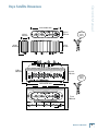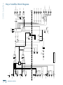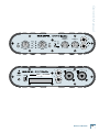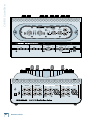
1
PORTABLE RECORDING PREAMP
with 96kHz FIREWIRE INTERFACE
O W N E R ’ S
M A N U A L
ONYX Satellite
Important Safety Instructions
1. Read these instructions. 13.Unplug this apparatus during lightning storms or when unused for long
periods of time.
2. Keep these instructions.
14.Refer all servicing to qualified service personnel. Servicing is required
when the apparatus has been damaged in any way, such as powersupply cord or plug is damaged, liquid has been spilled or objects have
fallen into the apparatus, the apparatus has been exposed to rain or
moisture, does not operate normally, or has been dropped.
3. Heed all warnings.
4. Follow all instructions.
5. Do not use this apparatus near water.
6. Clean only with dry cloth.
7. Do not block any ventilation openings. Install in accordance with the
manufacturer’s instructions.
8. Do not install near any heat sources such as radiators, heat registers,
stoves, or other apparatus (including amplifiers) that produce heat.
9. Do not defeat the safety purpose of the polarized or grounding-type
plug. A polarized plug has two blades with one wider than the other.
A grounding-type plug has two blades and a third grounding prong.
The wide blade or the third prong are provided for your safety. If the
provided plug does not fit into your outlet, consult an electrician for
replacement of the obsolete outlet.
10.Protect the power cord from being walked on or pinched particularly at
plugs, convenience receptacles, and the point where they exit from the
apparatus.
11.Only use attachments/accessories specified by the manufacturer.
12.Use only with a cart, stand, tripod, bracket, or table specified by the
manufacturer, or sold with the apparatus. When a cart is used, use
caution when moving the cart/apparatus combination to avoid injury
from tip-over.
PORTABLE CART WARNING
Carts and stands - The
Component should be used
only with a cart or stand
that is recommended by
the manufacturer.
A Component and cart
combination should be
moved with care. Quick
stops, excessive force, and
uneven surfaces may cause
the Component and cart
combination to overturn.
CAUTION
AVIS
RISK OF ELECTRIC SHOCK
DO NOT OPEN
RISQUE DE CHOC ELECTRIQUE
NE PAS OUVRIR
15.This apparatus shall not be exposed to dripping or splashing, and no
object filled with liquids, such as vases, shall be placed on the apparatus.
16.This apparatus does not exceed the Class A/Class B (whichever is
applicable) limits for radio noise emissions from digital apparatus as
set out in the radio interference regulations of the Canadian Department
of Communications.
ATTENTION — Le présent appareil numérique n’émet pas de bruits
radioélectriques dépassant las limites applicables aux appareils numériques de
class A/de class B (selon le cas) prescrites dans le réglement sur le brouillage
radioélectrique édicté par les ministere des communications du Canada.
17.Exposure to extremely high noise levels may cause permanent hearing
loss. Individuals vary considerably in susceptibility to noise-induced
hearing loss, but nearly everyone will lose some hearing if exposed to
sufficiently intense noise for a period of time. The U.S. Government’s
Occupational Safety and Health Administration (OSHA) has specified
the permissible noise level exposures shown in the following chart.
According to OSHA, any exposure in excess of these permissible limits
could result in some hearing loss. To ensure against potentially dangerous exposure to high sound pressure levels, it is recommended that all
persons exposed to equipment capable of producing high sound pressure levels use hearing protectors while the equipment is in operation.
Ear plugs or protectors in the ear canals or over the ears must be worn
when operating the equipment in order to prevent permanent hearing
loss if exposure is in excess of the limits set forth here.
Duration Per Day
In Hours
Sound Level dBA,
Slow Response
Typical
Example
8
90
6
92
Duo in small club
4
95
Subway Train
3
97
2
100
1.5
102
1
105
0.5 110
0.25 or less
115
Very loud classical music
Tami screaming at Adrian about deadlines
Loudest parts at a rock concert
CAUTION: TO REDUCE THE RISK OF ELECTRIC SHOCK
DO NOT REMOVE COVER (OR BACK)
NO USER-SERVICEABLE PARTS INSIDE
REFER SERVICING TO QUALIFIED PERSONNEL
ATTENTION: POUR EVITER LES RISQUES DE CHOC
ELECTRIQUE, NE PAS ENLEVER LE COUVERCLE. AUCUN
ENTRETIEN DE PIECES INTERIEURES PAR L'USAGER. CONFIER
L'ENTRETIEN AU PERSONNEL QUALIFIE.
AVIS: POUR EVITER LES RISQUES D'INCENDIE OU
D'ELECTROCUTION, N'EXPOSEZ PAS CET ARTICLE
A LA PLUIE OU A L'HUMIDITE
The lightning flash with arrowhead symbol within an equilateral
triangle is intended to alert the user to the presence of uninsulated
"dangerous voltage" within the product's enclosure, that may be
of sufficient magnitude to constitute a risk of electric shock to persons.
Le symbole éclair avec point de flèche à l'intérieur d'un triangle
équilatéral est utilisé pour alerter l'utilisateur de la présence à
l'intérieur du coffret de "voltage dangereux" non isolé d'ampleur
suffisante pour constituer un risque d'éléctrocution.
The exclamation point within an equilateral triangle is intended to
alert the user of the presence of important operating and maintenance
(servicing) instructions in the literature accompanying the appliance.
Le point d'exclamation à l'intérieur d'un triangle équilatéral est
employé pour alerter les utilisateurs de la présence d'instructions
importantes pour le fonctionnement et l'entretien (service) dans le
livret d'instruction accompagnant l'appareil.
ONYX Satellite
WARNING — To reduce the risk of fire or
electric shock, do not expose this apparatus
to rain or moisture.
Owner’s Manual
Table of Contents
Introduction.................................................................................................................................. 5
Onyx Satellite Features.........................................................................................................................................................6
Getting Started............................................................................................................................7
Computer Requirements.......................................................................................................................................................7
Installing the Windows Drivers...........................................................................................................................................7
Macintosh OS X Audio MIDI Setup.....................................................................................................................................7
Installing Tracktion 2.............................................................................................................................................................8
Zero the Controls...................................................................................................................................................................10
Connections.............................................................................................................................................................................10
Set the Levels...........................................................................................................................................................................11
Set the Sample Rate and Latency......................................................................................................................................11
Start Recording to DAW.......................................................................................................................................................12
Hookup Diagrams.......................................................................................................................13
Onyx Satellite Features.............................................................................................................17
Pod Front Panel......................................................................................................................................................................17
1. Channel GAIN...................................................................................................................................................................17
2. Signal Level Indicators..................................................................................................................................................17
3. Instrument Switch..........................................................................................................................................................17
4. POWER Indicator...........................................................................................................................................................17
5. FireWire Indicator..........................................................................................................................................................18
6. 48V Phantom Power Switch and Indicator .....................................................................................................................18
7. CTRL RM/PHONES 1 Level...........................................................................................................................................18
8. PHONES 2 Level..............................................................................................................................................................18
9. PHONES 1 and 2 Outputs..............................................................................................................................................18
Pod Rear Panel........................................................................................................................................................................19
10. MIC/Line Inputs...........................................................................................................................................................19
11. CR OUT.............................................................................................................................................................................19
12. TO DOCK Connector....................................................................................................................................................19
13. FIREWIRE........................................................................................................................................................................19
14. POWER Connector.......................................................................................................................................................19
15. Kensington Security Slot............................................................................................................................................19
Base Station Front Panel.....................................................................................................................................................20
16. MIC Input Select Switch............................................................................................................................................20
17. Instrument Input Select Switch...............................................................................................................................20
Don’t forget to visit our website at www.mackie.com for more
information about this and other Mackie products.
Part No. 0019085 Rev. A 06/06
©2006 LOUD Technologies Inc. All Rights Reserved.
R
Owner’s Manual
ONYX Satellite
18. Line Input 1 Select Switch.........................................................................................................................................20
19. Line Input 2 Select Switch.........................................................................................................................................20
20. Built-in Talkback Mic..................................................................................................................................................21
21. TALKBACK LEVEL Control...........................................................................................................................................21
22. TO PHONES Switch......................................................................................................................................................21
23. TO DAW Switch.............................................................................................................................................................21
24. CONTROL ROOM LEVEL Control.............................................................................................................................21
25. SOURCE Select Switch................................................................................................................................................21
26. A/B Select Switch...................................................................................................................................................... 22
27. 1-2/1-6 Select Switch.................................................................................................................................................. 22
28. Power Switch............................................................................................................................................................... 22
29. Base Station Dock....................................................................................................................................................... 22
Base Station Rear Panel.......................................................................................................................................................23
30. MIC Input.......................................................................................................................................................................23
31. LINE 1 Input.....................................................................................................................................................................23
32. LINE 2 Input....................................................................................................................................................................23
33. Instrument Input..........................................................................................................................................................23
34. INSERT Jacks..................................................................................................................................................................23
35. OUTPUTS 3-6................................................................................................................................................................24
36. CR OUT 1 and 2.............................................................................................................................................................24
37. FIREWIRE.......................................................................................................................................................................24
38. POWER Connector......................................................................................................................................................24
39. Kensington Security Slot...........................................................................................................................................24
Appendix A: Service Information..........................................................................................25
Warranty Service.................................................................................................................................................................. 25
Troubleshooting.................................................................................................................................................................... 25
Repair.......................................................................................................................................................................................26
Appendix B: Connections........................................................................................................27
Appendix C: Technical Info.....................................................................................................30
Onyx Satellite Specifications............................................................................................................................................30
Onyx Satellite Dimensions . ...............................................................................................................................................31
Onyx Satellite Block Diagram............................................................................................................................................32
Onyx Satellite Limited Warranty.......................................................................................... 35
Please write your serial number here for future
reference (i.e., insurance claims, tech support,
return authorization, etc.)
Purchased at:
Date of purchase:
ONYX Satellite
Thank you for choosing the Mackie Onyx Satellite
professional audio interface for studio and mobile
digital audio recording. The Onyx Series computer audio
interfaces are designed for the digital era and offer the
newest features and latest technologies for digital studio recording in a durable, road-worthy package.
The Onyx Satellite is equipped with two of our new
premium precision-engineered studio-grade Onyx mic
preamps. Mackie is renowned for the high-quality mic
preamps used in our mixers, and the Onyx mic pre’s are
better than ever, with specifications rivaling other standalone boutique mic preamplifiers at twice the price.
The Onyx Satellite is designed to be a transparent audio interface for direct tracking and mixdown, using high
performance 24-bit/96 kHz converters to provide wide
dynamic range and low noise. It works with virtually any
ASIO/Core Audio compliant DAW software application on
a PC or Mac as a 2x6 audio interface.
The unique docking feature allows you to set up the
Onyx Satellite in your studio, and leave it connected to
multiple mic, line, and instrument sources and studio
monitors, while “undocking” the portable pod to use
on location. This gives you the freedom to take the pod
into the field for overdubbing projects or live recordings
without having to constantly patch and unpatch the
cables that are connected to the base station.
The pod features a Neutrik™ Combo input connector
on channels 1-2, which allows you to use either a 1/4"
TRS connector or an XLR connector. A global 48V switch
applies phantom power to both XLR input connectors.
Channels 1 and 2 also feature an instrument select
switch, which lets you connect an acoustic, electric,
or bass guitar directly to the 1/4" input, eliminating
the need for an external direct box. The pod also has a
stereo control room output and two stereo headphone
jacks, each with separate level controls (the Control
Room and Phones 1 outputs share a level control), and a
FireWire connector to connect to your laptop.
When the pod is “docked” to the base station, it gains
additional features and expanded input and output capabilities. The base station has a separate XLR connector, two 1/4" TRS line-input connectors, and a 1/4" TS
instrument connector for each channel (channels 1-2),
with select switches for each input source. Insert jacks
are also provided for channels 1-2 to send and return
the signal to an external processor. These are pre-ADC
(Analog-to-Digital Converters) so they work great for
compressors and other dynamic processors.
Owner’s Manual
Introduction
Six channels of analog balanced line outputs are
provided on 1/4" TRS connectors. Two of these can be
used as stereo control room outputs, with an A/B switch
to route the signal to two separate pairs of monitors
for comparison. The built-in talkback microphone can
be routed to the phones/control room output or to the
DAW for slating. A FireWire connector provides a simple
connection to a laptop or desktop computer and allows
the audio to be streamed to and from your software of
choice.
Both units can be powered either directly from the
FireWire bus (when using a six-pin FireWire connector),
or from the 12V DC power supply included in the box.
As a bonus, Tracktion 2 is included with your Onyx
Satellite, our full-featured music production software
application for easy recording, mixing, and mastering on
a PC or Mac.
Pod
OL
-10
GAIN
-2
0
-4
0
POWE
R
GAIN
OL
-10
GAIN
-2
0
-4
0
POWE
R
GAIN
MIC
MIC
1
1
2
MIC
2
MIC
1
2
1
TO
PHON
ES
TO
DAW
2
TO
PHON
ES
TO
DAW
DAW
INPUTS
A
B
ON
Base Station
DAW
INPUTS
A
B
1-2
1-6
1-2
1-6
ON
Docked
Owner’s Manual
ONYX Satellite
HOW TO USE THIS MANUAL
ARCANE MYSTERIES ILLUMINATED
We know that many of you can’t wait to get your new
Onyx Satellite computer interface hooked up, and you’re
probably not going to read the manual first (sigh!). So
the first section after this introduction is a Quick-Start
Guide called “Getting Started” to help you get the Onyx
Satellite set up fast so you can start using it right away.
Right after that are the ever popular hook-up diagrams
that show typical setups for various recording applications.
“Arcane Mysteries” discusses some of the down ‘n’
dirty practical realities of microphones, fixed installations, grounding, and balanced versus unbalanced lines.
It’s a goldmine for the neophyte, and even the seasoned
pro might learn a thing or two.
Then, when you have time, read the Features Description section. This describes every knob, button, and
connection point on the Onyx Satellite.
• Innovative 2-piece FireWire Recording System for
professional recording on a PC or Mac
Throughout this section you’ll find illustrations with
each feature numbered. If you want to know more about
a feature, simply locate it on the appropriate illustration, notice the number attached to it, and find that
number in the nearby paragraphs.
This icon marks information that is
critically important or unique to the
Onyx Satellite. For your own good,
read them and remember them.
They will be on the final test.
This icon leads you to in-depth explanations of features and practical tips.
While not mandatory, they usually
have some valuable nugget of information.
A PLUG FOR THE CONNECTOR SECTION
Appendix B is a section on connectors: XLR connectors, balanced connectors, unbalanced connectors, and
the insert connectors used on the Onyx Satellite.
More resources on our website at www.mackie.com.
THE FAQs
Click on Support to find answers to many of your questions. The FAQ (Frequently Asked Questions) section is
filled with answers to many of the questions our Technical Support staff has fielded over the years.
THE FORUMS
Visit our forums to seek help from our online community of Mackie users.
THE GLOSSARY: A Haven of Non-Techiness for
the Neophyte
The “Glossary of Terms” is a fairly comprehensive
dictionary of pro-audio terms. If terms like “clipping,”
“noise floor,” or “unbalanced” leave you blank, refer to
this glossary for a quick explanation.
ONYX Satellite
Onyx Satellite Features
• Dual Onyx mic preamps for superior sound quality
versus competing interfaces
• 8 inputs for connection of microphones, line
sources, and instruments
• 6 line-level outputs
• 24-bit/96 kHz capable sound quality
• Built-in control room functions include talkback
and A/B monitor switching
• 6-channel volume control allows for surround sound
mixing
• Firewire protocol for low latency real-time recording
• Satellite pod can be bus powered for field use or
externally powered, for added convenience
• Works with all ASIO and Core Audio compatible
software, Mac and PC (also compatible with
GigaSampler GSIF drivers)
• Pod provides 2 in/2 out audio streams; “Docked” pod
and base station provide 2 in/6 out audio streams
• Bundled with full version of Tracktion 2 software for
a complete recording solution on a PC or Mac
• Indestructo Mackie construction holds up to the
rigors of field recording
4. You may get a “Security Warning” about running the
installer. It’s okay. Click “Run.”
READ THIS PAGE!!
Even if you’re one of those people
who never reads manuals, all we
ask is that you read these next few
pages (through page 12) now before
you begin using the Onyx Satellite.
You’ll be glad you did!
If you are using the Onyx Satellite with a PC running
Windows XP®, you need to install the Windows drivers
first. The Macintosh doesn’t require any additional drivers, but you will still want to install Tracktion 2. Refer to
page 8 for instructions on installing Tracktion 2 (page 10
for installing on a Mac).
Computer Requirements
These are the minimum computer requirements for
using the Onyx Satellite and installing Tracktion 2:
For the PC:
• Microsoft Windows XP SP2
• Pentium 4, Celeron, or Athlon XP processor
• 256 MB RAM
For the Mac:
• OS X 10.3.9
• G4 processor
• 256 MB RAM
It is important to note that the processor speed,
amount of RAM installed, and the size and speed of your
hard drive all contribute to the overall performance of
your recording system.
Installing the Windows Drivers
When connecting the Onyx Satellite to a PC, it is necessary to first install the Onyx FireWire Windows drivers
and Satellite Control Panel.
Important: DO NOT connect the Onyx Satellite to
your PC until you are instructed to do so during the
installation procedure.
Owner’s Manual
Getting Started
5. Follow the instructions for the rest of the installation procedure. When it is completed, your Onyx
Satellite is ready to use. The POWER and FireWire
indicators on the Satellite should both be lit.
6. The Onyx Satellite should now appear as a 2x6
audio interface available for any ASIO DAW (or
Gigasampler) application that you have installed on
your computer.
Note: It is still necessary to select the Onyx Satellite
as the audio device in the DAW software application’s
“Settings” window.
Macintosh OS X Audio MIDI
Setup
The Macintosh OS X has its own built-in system level
audio drivers, so you don’t need to install any additional
drivers or a separate control panel to use the Onyx
Satellite with a Macintosh.
OS X has a dedicated setup utility for audio and
MIDI. You can use the Audio Setup utility to change the
default audio input and output and general system settings on your Macintosh.
1. Connect the Onyx Satellite to your Macintosh using
the supplied FireWire cable.
2. Go to the Applications folder and open the Utilities
folder.
1. Insert the CD provided with the Onyx Satellite into
your CD drive.
2. The installation process should start automatically.
If it doesn’t, click “Start > Run > Browse” and navigate to the CD drive. Double-click the file named:
“DoubleClickToInstall.exe.”
3. Click “OK” in the Run window.
Owner’s Manual
ONYX Satellite
3. Double-click “Audio MIDI Setup.”
Installing Tracktion 2
The CD-ROM that came with your Onyx Satellite
also has the full version of Tracktion 2, our easy-to-use
multitrack recording and sequencing software for the PC
and Mac.
Note: After installing Tracktion 2, be sure to check our
website periodically for software updates (www.mackie.
com).
To install Tracktion 2 on a PC running Windows XP:
1. Insert the CD-ROM into the CD-ROM drive.
4. Click the Audio Devices tab, and select Onyx Satellite in the “Properties For” drop-down box.
2. Browse to the CD directory and open the “Tracktion 2”
folder. You can copy the folder called “Tracktion 2
Documentation” to your hard drive if you like, to
make it easier to access.
3. Double-click the file “TracktionSetup.exe”.
4. You may get a “Security Warning” about running the
installer. It’s okay. Click “Run.”
5. Here you can see the settings for the Onyx Satellite.
You can also choose to use the Onyx Satellite as
your default input or output, as well as designate it
to be used for system sound output.
5. The next window allows you to select the language
you want to use with Tracktion 2 (English, French,
German, or Spanish). Make your choice and click
“OK.”
6. You’re ready to go with any Mac OS X Core Audio
host application (i.e., Tracktion, Logic, Cubase,
Nuendo, Live, Digital Performer, etc.).
The Onyx Satellite should now appear as a 2x6 audio
interface available for any DAW application that you
have installed on your computer.
Note: It is still necessary to select the Onyx Satellite
as the audio device in the DAW software application’s
“Settings” window.
ONYX Satellite
9. Next you are asked to select the Start Menu Folder
where you would like the Tracktion shortcuts installed. We recommend you use the default location
used by the installer, but you can choose a different
location if you want by clicking the Browse button.
Then click “Next.”
Owner’s Manual
6. The Tracktion Setup Wizard opens. Click “Next” to
continue.
7. Next you will see the Tracktion License Agreement.
Read through the text and click “I accept the agreement.” Click “Next” to continue.
10. The next window gives you the options of creating
a desktop icon and creating a Quick Launch icon.
Select the additional icons you would like to install,
and click “Next” to continue.
8. The next window lets you choose the Destination
folder for installing the software files. We recommend
you use the default location used by the installer, but
you can choose a different location if you want by
clicking the Browse button. Then click “Next.”
11. The next window gives you a summary of the installation options you have selected. Click “Back” if
you want to make any changes. Click “Install” to
proceed with the installation.
Owner’s Manual
ONYX Satellite
12. When the installer has completed copying the files
into the destination folder, the “Completing the
Tracktion Setup Wizard” window opens. If you want
to launch Tracktion right away, click the “Launch
Tracktion” box. Click “Finish” to complete the
installation.
Authorizing Tracktion 2
There is an authorization code on the sleeve of the
CD-ROM that came with your Onyx Satellite. You can
authorize the software from within Tracktion or by going
to http://my.mackie.com.
From Tracktion 2:
1. Open Tracktion 2.
2. Tracktion detects that the software is unregistered
and notifies you that it is running in Demo Mode.
You can choose to continue or click the “Unlock”
button to authorize the software.
3. Follow the instructions for unlocking Tracktion.
From my.mackie.com:
1. Go to http://my.mackie.com
2. If you haven’t done so already, set up an account
by entering your email address and clicking “No, I
want to create an account.” Then click “Continue.”
13. Double-click the Tracktion.exe file in the destination folder to open Tracktion. (If you selected the
option during the installation, you can double-click
the Tracktion shortcut icon on your desktop.)
To install Tracktion 2 on a Mac running OS X
(version 10.3.9 or later):
1. Insert the CD-ROM into the CD-ROM drive.
3. Enter the information to setup your profile. Then
proceed to register Tracktion by clicking “Mackie
Product Registration.”
4. Select “Software” and “Tracktion v2 Music Production Software.”
5. Click “Click here to register Tracktion v2 online.”
2. Double-click the CD icon on the desktop and
double-click the file named “TracktionSetup.dmg”.
6. Enter the authorization code from the sleeve on
your CD-ROM in the License Number box. Then
click “Authorize.”
3. A Tracktion window opens. Drag the Tracktion icon
from the Tracktion window into the Applications folder.
Once you’ve installed and authorized the software,
proceed as follows:
Zero the Controls
1. Turn down the channel GAIN controls, and the
Control Room and Phones level controls.
2. Set all push button switches to their “out” positions.
3. Turn the POWER switch off.
Connections
4. Double-click the Tracktion file in the Applications
folder to open Tracktion.
Note: This tutorial assumes that you are using the Onyx
Satellite with the pod “docked” to the base station.
This demonstrates how to record guitar to your DAW
for tracking, and then record a vocal while monitoring the
guitar track already laid down:
1. Plug a guitar into channel 1 Instrument input and a
microphone into channel 2 MIC input. Push in the
Instrument switch on channel 1.
10
ONYX Satellite
Set the Sample Rate and Latency
3. If you are using the AC adapter with your Onyx
Satellite, turn on the Power switch.
On a PC:
Note: The Onyx Satellite is equipped
with a 6-pin FireWire connector and
comes with a 6-pin to 6-pin FireWire
cable. If your computer has a 4-pin
FireWire connector, you can use the
6-pin to 4-pin FireWire adapter included in the box
to make the connection, but the Onyx Satellite cannot be powered from the 4-pin connector (the two
missing pins carry the power). You will need to use
the AC adapter included with the Onyx Satellite.
4. If the microphone is a dynamic microphone, leave
the 48V switch out. If it is a condenser microphone,
push in the 48V phantom power button to turn on
the phantom power (applied to XLR inputs 1 and 2).
5. Connect the Control Room A outputs to a pair
of powered studio monitors (or to an amplifier
connected to a pair of monitors). Optionally, you
can connect a pair of headphones to one of the
PHONES jack on the pod to monitor the audio.
Set the Levels
To set the channel GAIN controls (on channels 1-2),
it’s not even necessary to hear what you’re doing in the
monitors. The following steps must be performed one
channel at a time.
1. Open the Onyx Satellite Control Panel (click Start
> Programs > Mackie Satellite > Satellite Console). Select the sample rate of your choice (44.1,
48, 88.2, or 96 kHz) and the latency setting.
Owner’s Manual
2. Connect the FireWire connector from the Onyx Satellite to the FireWire connector on your computer.
These values should be reflected in your DAW
software application, and it is important that they
match. If you are using Tracktion 2, click the “Settings” tab and then click “Audio Devices” to see the
sample rate and latency settings.
On a Mac:
1. Go to the Applications folder and open the Utilities
folder.
2. Double-click “Audio MIDI Setup.”
1. Play something into the selected input, either guitar
(channel 1) or vocal (channel 2). Be sure that the
volume of the input source is the same as it would
be during normal use. If it isn’t, you might have to
readjust these levels later.
2. Adjust the channel’s GAIN control so that the
“–20” and “–10” LEDs light frequently or continuously, and the “OL” LED doesn’t light at all (or only
flashes occasionally).
3. Repeat for each channel.
4. You can also monitor the input level with the input
metering of your DAW software application.
3. Click the Audio Devices tab and select Onyx
FireWire in the “Properties For” drop-down box.
4. You can change the sample rate setting in the Format
drop-down box. There is no latency setting here. That
setting is made in the DAW software application.
Latency (sometimes called buffer
size) describes the amount of time
it takes for audio to get in and out of
your software application. The lower
the latency setting, the faster audio
can get into and out of the software
Owner’s Manual
11
ONYX Satellite
application; in other words, the closer to zero delay you
will experience while recording. However, a low latency
setting requires more resources from your computer,
so you need to find a happy balance between finding
the lowest latency you can attain before the computer
begins to have trouble routing and recording audio (e.g.,
dropouts, pops, distorted audio).
Many DAW software applications have an ASIO control
panel. In Tracktion 2, it is located in the “Audio” window
under the “Settings” tab. Click the “Show ASIO control
panel” button (PC only) to open the ASIO control panel
for the Onyx Satellite. The latency setting in the ASIO
control panel should be the same as the latency selected
in the software application.
Start Recording to DAW
1. Select the Onyx Satellite as the sound device in
your DAW application. Each DAW application
has its own method of doing this, so refer to your
DAW application’s manual if you are not sure. In
Tracktion 2, this is done in the “Audio” window
under the “Settings” tab.
2. Assign the inputs from the Onyx Satellite to tracks
in your DAW.
3. You should now see the signals from the Onyx Satellite appearing on the meters in your DAW. Start
recording the guitar onto a track in the DAW.
4. Playback the recorded audio and assign the DAW
outputs to the Control Room Outputs (1 and 2) on
the Onyx Satellite.
5. Listen to the guitar playback on the headphones
while recording the vocal part. Make sure the Control Room Source Select switch on the Satellite is
out (DAW).
6. You can continue adding tracks to the arrangement,
and listen back over the Control Room monitors (or
headphones) when you are done.
12
ONYX Satellite
Other Nuggets of Wisdom
• You can connect the analog outputs from any
line-level source to the LINE INPUTS on the Onyx
Satellite and use its high-quality analog-to-digital
converters to get your analog signals to your digital
recorder(s).
• When the Pod is docked, the CTRL RM/PHONES 1
knob on the Pod adjusts only the Phones 1 output
(not the Control Room outputs). The CONTROL
ROOM LEVEL knob on the Base Station adjusts the
Control Room outputs. Use this control as close to
the MAX (fully clockwise) position as possible to
experience the best audio quality. Turn down the
input sensitivity control on your active monitors or
your passive monitors’ power amplifier in order to
turn up the CONTROL ROOM LEVEL knob as far as
possible.
• Always turn off the Onyx Satellite before removing
or connecting the Pod to the Base Station.
• When you shut down your equipment, turn off the
amplifiers first. When powering up, turn on the
amplifiers last.
• Never listen to loud music for prolonged periods.
Please see the Safety Instructions on page 2 for
information on hearing protection.
• Save the shipping box! You may need it someday,
and you don’t want to have to pay for another one.
That’s it for the “Getting Started” section. Next comes
the “Hookup” section that shows you some typical ways
that you might use the Onyx Satellite in real applications. After that, you can take the grand tour of the
Onyx Satellite, with descriptions of every knob, button,
input, and output. We encourage you to take the time
to read all of the feature descriptions, but at least you
know it’s there if you have any questions.
Headphones
For Musicians
(From Pod)
Owner’s Manual
Hookup Diagrams
Electric Guitar
Home Studio Recording
Powered
Studio Monitors
(Main)
Keyboard or other
line-level stereo input
Stereo Guitar
Effects
Condenser
Microphone
CR OUT
2/R
A
(BAL/UNBAL)
4
2
INPUT
OUTPUTS
1/L
3
2
LINE
LINE
1
INPUT
2
YX
ON
MIC P
R
LINE
LINE
1
1
YX
ON
E
MIC P
R
E
B
2/R
1/L
5
6
INSERT
INSERT
(TIP=SEND
RING=RETURN)
(TIP=SEND
RING=RETURN)
Electric Guitar
(to Instrument Input)
Bass Guitar
(to Instrument Input)
Powered
Studio Monitors
(Nearfield)
Out In
Out In
Compressor
Equalizer
Remote Recording
Electric Guitar
(Instrument Button In)
Headphones
For Engineer and Musician
(on Front Panel)
Condenser
Microphone
CTRL RM
L
POWER
FW
T59052
ON
YX MIC PRE
2
ON
YX MIC PRE
1
DATE CODE
TO DOCK
R
(BAL/UNBAL)
This example demonstrates how the Satellite can be set up in a home studio application with
multiple input sources connected to the base station along with two sets of monitors and a laptop
connected to the FireWire connection on the Satellite.
The Satellite Pod can then be removed and taken to a second location for overdubbing additional
vocal and guitar tracks, leaving all the connections to the base station intact.
Typical Home Studio Setup/Pod Remote Location Recording
Owner’s Manual
13
ONYX Satellite
Left and Right
Front
Left and Right
Rear
Video Deck 2
Video Deck 1
Condenser
Microphone
CR OUT
2/R
A
INPUT
OUTPUTS
1/L
4
(BAL/UNBAL)
3
2
LINE
LINE
1
2
INPUT
2
LINE
LINE
B
2/R
1/L
6
5
INSERT
(TIP=SEND
RING=RETURN)
INSERT
(TIP=SEND
RING=RETURN)
Digital Audio Workstation
Subwoofer
Center
This illustrates a 5.1 surround sound setup using two video decks connected to Line 1 and 2 on Inputs 1 and 2. A microphone is connected to
the mic input on Input 1 for voiceover.
Onyx Satellite: Post-Production and Surround Mixing
14
ONYX Satellite
1
YX MIC PR
E
ON
YX MIC PR
E
ON
1
Headphones
For Engineer
(Front Panel)
Owner’s Manual
Condenser
Microphones
in X-Y Configuration
for stereo recording
of a choral group or jazz combo
CTRL RM
L
POWER
FW
T59052
ON
YX MIC PRE
2
ON
1
YX MIC PRE
DATE CODE
TO DOCK
R
(BAL/UNBAL)
This illustrates how to use the Satellite Pod to make a live stereo recording
using an X-Y microphone placement. The recording is made to two tracks
in the DAW software on the laptop.
Afterward, you can plug the pod into the base station and play back the
recording through monitors connected to the Control Room outputs.
Condenser
Microphones
in X-Y Configuration
for stereo recording
of a choral group or jazz combo
Headphones
For Engineer
(Front Panel)
CTRL RM
L
POWER
CD Recorder
FW
T59052
ON
YX MIC PRE
2
ON
YX MIC PRE
1
DATE CODE
TO DOCK
R
(BAL/UNBAL)
Same scenario as above, but using the Pod in standalone mode without a
computer. The Control Room outputs are connected to the inputs of a CD
recorder or other recording device to make a stereo recording in the field.
Onyx Satellite Pod Remote Direct-to-2 Track Recording
Owner’s Manual
15
ONYX Satellite
Television
Left and Right
Powered Speakers
L/R Audio Out
L/R Audio Out
CR OUT
2/R
A
INPUT
OUTPUTS
1/L
4
(BAL/UNBAL)
3
2
LINE
LINE
2
1
INPUT
2
LINE
LINE
Dock
MP3 Player
1
1
YX MIC PR
E
ON
YX MIC PR
E
ON
B
2/R
1/L
6
5
INSERT
(TIP=SEND
RING=RETURN)
INSERT
(TIP=SEND
RING=RETURN)
For some just starting out with their own home studio, it may be necessary to use the
home stereo speakers for monitors. But what happens when the engineer in the family
is off somewhere with his laptop? The Satellite can be used as a preamp for a living
room or bedroom stereo system. No laptop required! Simply connect the signal sources
(i.e., the outputs from an MP3 player or the stereo audio output from your television
tuner) to the Satellite inputs, and connect the Control Room outputs to a pair of powered speakers (or to the inputs of an amplifier with speakers connected). Push in the
Control Room Source button (Inputs) and the selected inputs are routed to the Control
Room outputs. Use the Control Room knob to adjust the volume.
Onyx Satellite As Stereo Preamp
16
ONYX Satellite
Pod Front Panel
The Onyx Satellite is uniquely designed to be set up in
your studio with all the inputs and outputs connected,
and allows you to remove the pod from the base station
for portable use in the field.
The pod provides two Neutrik combination Mic/Line
inputs with independent Gain controls, a global 48V
phantom power switch, stereo line-level control room
outputs, two stereo headphone jacks with independent level controls (one shared with the control room
outputs), and a FireWire connector. Each input channel
also has an instrument switch that converts the 1/4" line
input into a high-impedance instrument input so you
can connect electric instruments directly to the Onyx
Satellite without a direct box.
1. Channel GAIN
The GAIN controls adjust the input sensitivity of the
mic and line inputs on channels 1-2. This allows the
signal from the outside world to be adjusted to optimal
internal operating levels.
If a mic-level signal is plugged into the XLR combo
jack, there is 0 dB of gain (unity gain) with the knob
turned all the way down, ramping up to 60 dB of gain
fully up.
When using the balanced line input of the combo jack
(1/4" TRS connector), there is 20 dB of attenuation
all the way down, and 40 dB of gain fully up, with a “U”
(unity gain) mark at about 10:00.
2. Signal Level Indicators
These LEDs indicate the channel’s signal level after
the GAIN control and just after the analog-to-digital
converter.
30
20
40
-10
20
-20dB
60
+40dB
GAIN
-40
U
-20dB
Channels 1 and 2 have a button for switching the
1/4" line input to an instrument input. When the button is out, the 1/4" input accepts normal line-level
signals from low-impedance sources. When the button
is pushed in, the 1/4" input accepts high-impedance
signals from instruments with electric pickups, which
you would normally run through a DI box.
Plugging a guitar straight into a typical line input can result in the loss of
high frequencies, causing an unnatural and dull sound. Normally, you
must use a direct box between a guitar
and a mixer’s or preamplifier’s input,
which serves to convert the impedance of the guitar
from high to low. The Instrument inputs on channels 1
and 2 make the need for a direct box unnecessary.
HOWEVER: The Instrument inputs are unbalanced, so
if you are running a long cord between the instrument
and the Onyx Satellite (say over 20 feet), it is best to use
a direct box with a balanced output to avoid picking up
noise over the length of the cord.
4. POWER Indicator
When power is applied to the pod, either through the
FireWire connection or with the AC adapter, the POWER
LED lights to let you know the unit is operational.
PHONES 2
1
POWER
U
40
-20
U
3. Instrument Switch
CTRL RM/
PHONES 1
30
OL
U
If you’ve followed the “Set the Levels” procedure on
page 11, the –20 and –10 LEDs should light frequently,
and the OL (Overload) LED should not light at all. If
the OL LED is blinking frequently, the signal is probably
distorted from overdriving the input. Either turn down
the GAIN control or turn down the signal at its source.
Owner’s Manual
Onyx Satellite Features
60
+40dB
2
48V
OO
MAX
OO
MAX
GAIN
Owner’s Manual
17
ONYX Satellite
5. FireWire Indicator
8. PHONES 2 Level
This LED illuminates when a valid FireWire connection is made between the Onyx Satellite and a computer.
This knob adjusts the signal level at the PHONES 2
jack [9] on the front panel. It ranges from off (∞) to
maximum gain (MAX).
6. 48V Phantom Power Switch and Indicator
Most professional condenser microphones require
phantom power, which is a low-current DC voltage
delivered to the microphone on pins 2 and 3 of the XLR
microphone connector. Push in the 48V button if your
microphone requires phantom power. An LED lights
next to the button to indicate that phantom power is
active.
This is a global phantom power switch and applies
48V to the XLR input connectors on channels 1 and 2.
Dynamic microphones, like Shure’s SM57 and SM58,
do not require phantom power. However, phantom
power will not harm most dynamic microphones should
you accidentally plug one in while the phantom power
is turned on. Be careful with older ribbon microphones.
Check the manual for your microphone to find out for
sure whether or not phantom power can damage it.
7. CTRL RM/PHONES 1 Level
Use this knob to adjust the signal level at the CTRL
RM Out [11] jacks on the rear panel of the pod. It also
adjusts the signal at the PHONES 1 [9] jack on the
front, since they share the same signal. It ranges from
off (∞) to maximum gain (MAX).
30
20
40
-10
20
-20dB
18
60
+40dB
GAIN
ONYX Satellite
-40
U
-20dB
This is where you plug in your stereo headphones.
These are 1/4" TRS stereo jacks. The same signal appears at both PHONE jacks, but each has its own individual level control [7/8]. The same signal is also routed
to the CONTROL ROOM outputs [11], which share the
level control with the PHONES 1 output.
WARNING: The headphone amps are
designed to drive any standard headphones to a very loud level. We’re not
kidding! They can cause permanent
hearing damage. Even intermediate
levels may be painfully loud with
some headphones.
BE CAREFUL! Always start with the PHONES level
turned all the way down before connecting headphones
to the PHONES jack. Keep it down until you’ve put on
the headphones. Then turn it up slowly. Why? Always
remember: “Engineers who fry their ears, find themselves with short careers.”
PHONES 2
1
POWER
U
40
-20
U
9. PHONES 1 and 2 Outputs
CTRL RM/
PHONES 1
30
OL
U
Having independent level control for each headphone
output means that in an overdub situation, for example,
the musician and the engineer can each adjust their
own headphone volume to taste.
60
+40dB
GAIN
2
48V
OO
MAX
OO
MAX
10. MIC/Line Inputs
These are Neutrik combo connectors, which accept
balanced microphone inputs from an XLR connector, or
balanced line-level or instrument inputs from a 1/4" TRS
connector. The microphone preamps feature our new
Onyx design, with higher fidelity and headroom rivaling
any standalone mic preamp on the market today.
The FireWire interface provides two inputs to your
DAW software application (inputs 1-2). The FireWire
interface on the pod also provides a return for two channels from the DAW, which can be routed back to the control room/phones outputs to monitor the computer audio
through your control room speakers or headphones.
Note: When the pod is docked to the base station, up to
six channels can be returned from the DAW for monitoring purposes.
The FireWire interface works with both PC and Mac.
The XLR inputs are wired as follows:
Pin 1 = Shield or ground
Pin 2 = Positive (+ or hot)
Pin 3 = Negative (– or cold)
The 1/4" inputs are wired as follows and will accept
both balanced and unbalanced inputs:
Sleeve = Shield or ground
Tip = Positive (+ or hot)
Ring = Negative (– or cold)
11. CR OUT
These 1/4" TRS jacks provide a balanced or unbalanced line-level signal that can be used to provide a
monitor mix to a pair of powered studio monitors, or an
additional headphone mix to a headphone amplifier.
The signal at the CR OUTs is the same signal that appears at the PHONES 1 and 2 Out [9].
12. TO DOCK Connector
If your laptop or desktop computer
does not have a FireWire connection,
you can purchase a PCI or PCMCIA
FireWire card and install it in your
computer easily and inexpensively.
Owner’s Manual
Pod Rear Panel
14. POWER Connector
Normally, the Onyx Satellite can be powered from
the FireWire connector (which provides 12V DC for
powering devices). However, if you are using a 4-pin
FireWire connector instead of a 6-pin connector (the
4-pin connector doesn’t provide power), or if you have
two or more devices daisy-chained on a single connector, you need to use the AC adapter that came with
your Onyx Satellite.
Connect the AC adapter to the Onyx Satellite first,
then plug the adapter into a suitable and properly rated
AC outlet.
15. Kensington Security Slot
This multipin connector mates with the base station
docking connector and allows the pod and the base station to share their circuits.
13. FIREWIRE
To help prevent theft, this security slot is designed to
fit the popular Kensington security locks. A variety of
models are available from their website at
www.kensington.com.
FireWire (a.k.a. IEEE 1394) is a high-speed serial I/O
interface for connecting digital devices, with more than
30 times the bandwidth of USB 1.1.
CTRL RM
L
POWER
FW
T59052
ON
YX MIC PRE
2
ON
YX MIC PRE
1
DATE CODE
TO DOCK
R
(BAL/UNBAL)
Owner’s Manual
19
ONYX Satellite
Base Station Front Panel
16. MIC Input Select Switch
When the pod is connected to the base station, some
additional features become available above and beyond
those that are present when using the pod by itself.
Press this button to select the XLR Mic input as the
input source for the channel.
• More inputs are available to select for each channel
(Mic, Instrument, Line 1, and Line 2)
• An insert jack (send/return) is available for each
channel
• An additional stereo control room output is available (A and B)
• A separate control room level control can operate
on just the A/B outputs, or on all six outputs as a
master level control
• The control room source can be switched between
the Core Audio/ASIO streams 1 and 2 from the DAW
software application, and the inputs from the Onyx
Satellite
• A built-in Talkback Mic is available for routing to
the phones and to the DAW application
Note: The base station does not function when the pod is removed. The pod
is the “brains” and the base station
simply provides more connections and
controls than the pod does by itself.
1
1
2
2
MIC
1
2
Press this button to select the Instrument input (
as the input source for the channel.
Note: The instrument switch on the pod must also be
pushed in to select the instrument input.
Press this button to select LINE 1 as the input source
for the channel.
19. Line Input 2 Select Switch
Press this button to select LINE 2 as the input source
for the channel.
Note: You can select and combine the
Mic, Instrument, Line 1, and Line 2
inputs for each channel from the base
station. However, the base station has
no provision for matching the impedances or the input level of the combined signals, so it is best only to combine similar signals
(for example, line-level signals connected to Input 1 and
Input 2), or to select only one input at a time.
TALKBACK
TO
PHONES
MAX
LEVEL
ONYX Satellite
CONTROL ROOM
TO
DAW
OO
20
)
18. Line Input 1 Select Switch
• Four more line-level outputs are available (for a
total of six, including the control room outputs)
MIC
17. Instrument Input Select Switch
DAW
INPUTS
SOURCE
A
B
OO
MAX
LEVEL
1-2
1-6
ON
This is where the built-in talkback microphone is located. This is an omni-directional dynamic microphone,
so it will pick up your voice from anywhere in front
of the unit. In addition, the talkback signal is routed
through a compressor, which allows the talkback signal
to maintain a constant volume regardless of how far you
are from the Onyx Satellite (within reason).
21. TALKBACK LEVEL Control
Use this knob to adjust the level of the talkback signal.
You should start with the TALKBACK LEVEL control
turned down, and then slowly turn it up until you get
confirmation from whoever is listening to the headphones
that they can hear you. Once you have set the level, you
can leave it there for the duration of the session.
If you are using the talkback mic to slate takes in your
DAW, use the meters in your DAW to adjust the TALKBACK LEVEL control.
22. TO PHONES Switch
Press this button to route the talkback signal to both
PHONES outputs on the pod. This is a momentary
switch and is only active as long as you hold the button
down. This allows you to talk to the talent without them
having to remove their headphones.
23. TO DAW Switch
mentary switch and is only active as long as you hold
the button down. This allows you to slate takes as you
record to the DAW.
Note: When you press either of the Talkback switches,
the control room outputs are attenuated momentarily so
the engineer can hear himself or herself talk.
24. CONTROL ROOM LEVEL Control
Use this knob to adjust the signal level at the CR OUT
[36] jacks on the rear panel. It adjusts the signal for
both the left and right Control Room A/B outputs, ranging from off (∞) to maximum gain (MAX).
Owner’s Manual
20. Built-in Talkback Mic
25. SOURCE Select Switch
Use this switch to select the signal source for the
control room outputs. When the switch is up (DAW),
the Core Audio/ASIO streams 1 and 2 from the DAW
application are routed to the control room outputs. Use
this to monitor tracks already recorded and to overdub
additional tracks.
When the switch is down (INPUTS), channels 1 and
2 from the Onyx Satellite are routed to the control room
outputs. This allows you to listen to whatever is connected to the Onyx Satellite without having a computer
connected. Maybe you have a CD player or iPod connected to the Onyx Satellite and you want to listen to
it through your control room monitor speakers. Voila!
This is particularly useful when you have a home studio
setup that does double-duty as a home stereo system.
Press this button to route the talkback signal to
channels 1 and 2 being fed to the DAW. This is a mo-
1
MIC
1
2
2
MIC
1
2
TALKBACK
TO
PHONES
CONTROL ROOM
TO
DAW
OO
MAX
LEVEL
DAW
INPUTS
SOURCE
A
B
OO
1-2
1-6
ON
MAX
LEVEL
Owner’s Manual
21
ONYX Satellite
26. A/B Select Switch
28. Power Switch
This switch determines which pair of control room
outputs is currently active. Only one pair of control
room outputs provides an output signal at any one time.
This allows you to have two sets of monitors connected
to the Onyx Satellite so you can make quick A/B comparisons between them to make sure your mix sounds
good on both pairs of monitor speakers.
This switch turns the power on and off to the Onyx
Satellite. When the power switch is on and power is supplied to the Onxy Satellite, either through the FireWire
connector or the DC power supply, the POWER LED [4]
on the pod lights up.
27. 1-2/1-6 Select Switch
The pod plugs into the base station here. Align the
“TO DOCK” [12] connector on the pod with the connector in the base station dock and push firmly to insure a
secure connection.
When this switch is up (1-2), the CONTROL ROOM
LEVEL control [24] adjusts the level at the CR OUTS
(1-2) on the rear panel of the base station. When the
switch is down (1-6), the CONTROL ROOM LEVEL
control adjusts the level at all six outputs. This is useful
when mixing in surround sound to provide a master
level control for all the surround stems.
29. Base Station Dock
Note: When the select switch is up (1-2), outputs 3-6 are
not adjustable from the Onyx Satellite, but remain fixed.
This is useful for:
• Dialing up some alternate headphone mixes with
aux sends from the DAW, and then sending them to
the line-level inputs of a headphone amplifier
• Sending a recorded track to an outboard analog processor, like a compressor or EQ
• Transferring a mix to an analog recorder for flavor
(like an old reel-to-reel recorder!)
1
MIC
1
2
2
MIC
1
2
TALKBACK
TO
PHONES
OO
MAX
LEVEL
22
ONYX Satellite
CONTROL ROOM
TO
DAW
DAW
INPUTS
SOURCE
A
B
OO
MAX
LEVEL
1-2
1-6
ON
33. Instrument Input
30. MIC Input
This is a 1/4" TS connector that accepts an unbalanced
instrument-level input signal from a high-impedance
instrument like a guitar.
This is a female XLR connector, which accept balanced microphone inputs from almost any type of
microphone. The microphone preamps feature our new
Onyx design, with higher fidelity and headroom rivaling
any standalone mic preamp on the market today.
34. INSERT Jacks
These 1/4" TRS jacks provide a send and return point
for channels 1-2. Use the INSERT jacks to connect serial
effects devices such as compressors, equalizers, de-essers,
or filters to each individual channel.
The XLR inputs are wired as follows:
Pin 1 = Shield or ground
Pin 2 = Positive (+ or hot)
Pin 3 = Negative (– or cold)
The INSERT points are after the GAIN controls, and
just before the analog-to-digital converters. The send
(tip) is low-impedance, capable of driving any device.
The return (ring) is high-impedance and can be driven
by almost any device.
31. LINE 1 Input
This is a 1/4" TRS connector, which accepts a balanced or
unbalanced line-level input signal from almost any source.
Tip: Since the inserts are before the
A/D converters, it’s a good place to
strap a compressor on an unruly singer to avoid overloading the A/D converter without having to turn down
the GAIN control a whole bunch.
When connecting a balanced signal to the LINE
inputs, wire them as follows:
Tip = Positive (+ or hot)
Ring = Negative (– or cold)
Sleeve = Shield or ground
Special insert cables are available, specially designed
for this kind of insert jack. They are wired as follows:
When connecting an unbalanced signal, wire them
as follows:
Tip = Positive (+ or hot)
Sleeve = Shield or ground
tip
SEND to processor
ring
(TRS plug)
sleeve
this plug connects to one of the
mixer’s Channel Insert jacks.
32. LINE 2 Input
This is a 1/4" TRS connector, which provides a second
line-level input for each channel. It works the same as
the LINE 1 input.
CR OUT
2/R
A
4
(BAL/UNBAL)
INPUT
3
2
LINE
“from tip”
“to ring”
RETURN from processor
Tip = Send (output to effects device)
Ring = Return ( input from effects device)
Sleeve = Common ground (connect shield to all three sleeves)
OUTPUTS
1/L
Owner’s Manual
Base Station Rear Panel
LINE
1
2
INPUT
2
YX
ON
MIC P
R
LINE
LINE
YX
ON
E
1
1
MIC P
R
E
B
2/R
1/L
6
5
INSERT
(TIP=SEND
RING=RETURN)
INSERT
(TIP=SEND
RING=RETURN)
Owner’s Manual
23
ONYX Satellite
Besides being used for inserting external devices,
these jacks can also be used as channel direct outputs
(post-GAIN). This is an unbalanced direct out.
Here are three ways you can use the INSERT jacks:
MONO PLUG
Channel Insert jack
Direct out with no signal interruption to master.
Insert only to first “click.”
MONO PLUG
Channel Insert jack
Direct out with signal interruption to master.
Insert all the way in to the second “click.”
STEREO
PLUG
Channel Insert jack
For use as an effects loop.
(TIP = SEND to effect, RING = RETURN from effect)
36. CR OUT 1 and 2
These 1/4" TRS jacks provide a balanced line-level
signal that can be used to provide a monitor mix to a pair
of powered studio monitors, or an additional headphone
mix to a headphone amplifier.
There are two pairs of Control Room outputs labeled
A and B. These are selected using the A/B Select switch
[26] in the Control Room section on the front panel of
the base station. The same signal is routed to both stereo
control room outputs, as well as the PHONES 1 and 2
outputs.
37. FIREWIRE
When the pod is connected to the base station, the
FireWire connector on the base station is activated
and used to connect to your computer. It operates in
the same way as described for the FireWire connector
on the pod [13], except that up to six tracks can be
returned from your DAW to the Onyx Satellite instead of
just two.
38. POWER Connector
35. OUTPUTS 3-6
These 1/4" TRS output connectors provide balanced
or unbalanced line-level analog signals. The signal at
the LINE OUTs are assigned in the DAW application as
follows:
Output 3 = Core Audio/ASIO out 3
Output 4 = Core Audio/ASIO out 4
Output 5 = Core Audio/ASIO out 5
Output 6 = Core Audio/ASIO out 6
Normally, the Onyx Satellite can be powered from the
FireWire connector (which provides 12V DC for powering devices). However, if you are using a 4-pin FireWire
connector instead of a 6-pin connector (the 4-pin
connector doesn’t provide power), or if you have two or
more devices daisy-chained on a single connector, you
need to use the AC adapter that came with your Onyx
Satellite.
Connect the AC adapter to the Onyx Satellite first,
then plug the adapter into a suitable and properly rated
AC outlet.
39. Kensington Security Slot
To help prevent theft, this security slot is designed to
fit the popular Kensington security locks. A variety of
models are available from their website at
www.kensington.com.
CR OUT
2/R
A
INPUT
OUTPUTS
1/L
4
(BAL/UNBAL)
3
2
LINE
LINE
1
2
INPUT
2
YX
ON
MIC P
R
LINE
24
ONYX Satellite
1/L
6
5
INSERT
(TIP=SEND
RING=RETURN)
1
YX
ON
E
B
2/R
LINE
INSERT
(TIP=SEND
RING=RETURN)
MIC P
R
E
1
Warranty Service
Details concerning Warranty Service are spelled out in
the Warranty section on page 35.
• Is the signal source turned up? Make sure the signal
level from the selected input source is high enough
to light up some of the INPUT meter [2] LEDs for
that channel.
• If the pod is docked to the base station, make sure
the Input Select switches [16-19] are in the right
position.
If you think your Onyx Satellite has a problem, please do
everything you can to confirm it before calling for service.
Review the following Troubleshooting section. Visit the
Support page on our website (www.mackie.com) and
check out the FAQs and the users forums for help.
• If the Instrument Input [17] is selected, make sure
the Instrument button [3] is pushed in on the pod.
These may sound obvious to you, but here are some
things you can check. Read on.
• Try the same source signal in the other channel, set
up exactly like the suspect channel.
Troubleshooting
Bad Output
No Power
• If you are using the FireWire connection to power
the Onyx Satellite, make sure it is a six-pin connector (the smaller 4-pin connectors do not provide
power).
• If you are using the AC adapter, make sure the
power cord is securely seated in the POWER socket
[14/38] in the pod or the base station, and plugged
all the way into the AC outlet.
• Make sure the AC outlet is live (check with a tester
or lamp).
• Is the POWER [28] switch on? Make sure the
POWER switch on the front panel of the base station is in the ON position (up).
Note: If you are using the pod by itself, it does not
have a power switch and is powered up whenever
the FireWire or the AC adapter connection is made.
• Is the POWER LED on the pod illuminated? If not,
make sure the AC outlet is live (when using the AC
adapter) or the FireWire connection is good. Try
using another FireWire connection, if available.
• If there are no LEDs illuminated on the front panel,
and you are certain that the AC outlet is live (if
using the AC adapter) or the FireWire connection is
good, it will be necessary to have your Onyx Satellite
serviced. There are no user serviceable parts inside.
Refer to “Repair” at the end of this section to find out
how to proceed.
Bad Channel
• Is the input GAIN control [1] for the channel
turned up?
Owner’s Manual
Appendix A: Service Information
• If another output is working correctly, try switching
the output connections between the working output
and the suspect output. If the working output stops
working, it could be a bad cable or the device to
which it is connected.
Bad Sound
• Is the input connector plugged completely into the
jack?
• Is it loud and distorted? Make sure the input GAIN
control [1] for the channel is set correctly. Reduce
the signal level on the input source if possible.
• If possible, listen to the signal with headphones
plugged into the input source device. If it sounds
bad there, it’s not the Onyx causing the problem.
Noise/Hum
• Turn down each channel, one by one. If the noise
disappears, it’s coming from whatever is plugged
into that channel.
• Check the signal cables between the input sources
and the Onyx. Disconnect them one by one. When
the noise goes away, you’ll know which input source
is causing the problem.
No Audio into your Computer
• Confirm that the Onyx Satellite is receiving mic
or line-level input signals (the meters [2] should
indicate signal is present).
• Make sure the correct driver is selected in the DAW.
In Tracktion, this is selected in the Settings tab
under Audio.
• If the Onyx Satellite seems to be working fine and
you are using Tracktion, click Restart Device in the
Settings tab under Audio. Other DAW applications
may have a similar button.
Owner’s Manual
25
ONYX Satellite
• In Tracktion, be sure the correct inputs are selected
and the tracks are armed.
• Restart your Onyx Satellite and computer.
• Reinstall the drivers from the CD (PC only).
Glitchy/Distorted Audio into your Computer
4. Pack the Onyx Satellite in its original package,
including endcaps and box. This is VERY IMPORTANT. When you call for the Service Request
Number, please let Tech Support know if you need
new packaging. Mackie is not responsible for any
damage that occurs due to non-factory packaging.
• Increase the buffer size. This can be done in the
Onyx Satellite Control Panel or in your DAW application.
5. Include a legible note stating your name, shipping
address (no P.O. boxes), daytime phone number,
Service Request Number, and a detailed description
of the problem, including how we can duplicate it.
Repair
6. Write the Service Request Number in BIG PRINT on
top of the box. Units sent without the Service Request
Number will be refused.
Service for Mackie products is available at a factoryauthorized service center. Service for Mackie products
living outside the United States can be obtained through
local dealers or distributors.
If your Onyx Satellite needs service, follow these instructions:
1. Review the preceding troubleshooting suggestions.
Please.
2. Call Tech Support at 1-800-898-3211, 7 am to 5 pm
PST, to explain the problem and obtain a Service
Request Number. Have your Onyx Satellite’s serial
number ready.
You must have a Service Request Number before
you can obtain factory-authorized service.
3. Keep this owner’s manual and the detachable DC
power supply. We don’t need them to repair the
Onyx Satellite.
7. Tech Support will tell you where to ship the Onyx
Satellite for repair. We suggest insurance for all
forms of cartage.
8. You will need to contact the authorized service
center for their latest turn-around times. The Onyx
Satellite must be packaged in its original packing
box, and must have the Service Request Number on
the box. Once it’s repaired, the authorized service
center will ship it back, pre-paid (if it was a warranty repair).
Note: Under the terms of the warranty, you must
ship or drop-off the unit to an authorized service
center. The return ground shipment is covered for
those units deemed by us to be under warranty.
Note: You must have a sales receipt from an Authorized Mackie Dealer to qualify for a warranty repair.
Need Help?
Visit our website at www.mackie.com and click Support.
Check out the FAQs and the users forums
to find answers to your questions.
If you still need help, email us at [email protected]
or you can reach a technical support representative
Monday through Friday
from 7 AM to 5 PM PST at:
1-800-898-3211
R
26
ONYX Satellite
XLR Connectors
Channels 1-4 accept 3-pin male XLR connectors on
the Neutrik combo inputs. They are wired as follows,
according to standards specified by the AES (Audio
Engineering Society).
2
SHIELD
HOT
COLD
SHIELD
1/4" TS Phone Plugs and Jacks
“TS” stands for Tip-Sleeve, the two connection points
available on a mono 1/4" phone jack or plug. They are
used for unbalanced signals like the high-impedance
instrument inputs on the Onyx Satellite.
1
3
SLEEVE
SLEEVE
Owner’s Manual
Appendix B: Connections
TIP
1
TIP
TIP
COLD 3
HOT
1
3
2
COLD
2
SLEEVE
SHIELD
HOT
XLR Balanced Wiring:
Pin 1 = Shield
Pin 2 = Hot (+)
Pin 3 = Cold (–)
1/4" TRS Phone Plugs and Jacks
“TRS” stands for Tip-Ring-Sleeve, the three connection
points available on a stereo 1/4" or balanced phone
jack or plug. TRS jacks and plugs are used for balanced
signals and stereo headphones.
1/4" TS Unbalanced Wiring:
Sleeve = Shield
Tip = Hot (+)
RCA Plugs and Jacks
RCA-type plugs (also known as phono plugs) and jacks
are often used in home stereo and video equipment, and
to make S/PDIF connections on consumer digital audio
devices (they are not used on the Onyx Satellite). They
are unbalanced and electrically equivalent to a 1/4" TS
phone plug.
Balanced Mono
SLEEVE
RING SLEEVE
TIP SLEEVE
TIP
SLEEVE RING TIP
TIP
RING
TIP
RCA Unbalanced Wiring:
Sleeve = Shield
Tip = Hot (+)
SLEEVE
Unbalancing a Line
1/4" TRS Balanced Mono Wiring:
Sleeve = Shield
Tip = Hot (+)
Ring = Cold (–)
Stereo Headphones
RING SLEEVE
SLEEVE RING TIP
TIP
RING
TIP
SLEEVE
1/4" TRS Stereo Unbalanced Wiring:
Sleeve = Shield
Tip = Left
Ring = Right
In most studio, stage, and sound reinforcement situations, there is a combination of balanced and unbalanced inputs and outputs on the various pieces of
equipment. This usually will not be a problem in making
connections.
• When connecting a balanced output to an unbalanced input, be sure the signal high (hot) connections are wired to each other, and that the balanced
signal low (cold) goes to the ground (earth)
connection at the unbalanced input. In most cases,
the balanced ground (earth) will also be connected
to the ground (earth) at the unbalanced input. If
there are ground-loop problems, this connection
may be left disconnected at the balanced end.
Owner’s Manual
27
ONYX Satellite
• When connecting an unbalanced output to a balanced input, be sure that the signal high (hot)
connections are wired to each other. The unbalanced ground (earth) connection should be wired
to the low (cold) and the ground (earth) connections of the balanced input. If there are ground-loop
problems, try disconnecting the unbalanced ground
(earth) connection from the balanced input ground
(earth) connection, leaving the unbalanced ground
connected to the balanced input low (cold) connection only.
In some cases, you may have to make up special
adapters to interconnect your equipment. For example,
you may need a balanced XLR female connected to an
unbalanced 1/4" TS phone plug. Many common adapters
can be found at your local electronics supply store.
TRS Send/Receive Insert Jacks
Mackie’s single-jack inserts are three-conductor 1/4"
TRS phone jacks. They are unbalanced, but have both
the preamp output (send) and input (return) signals in
one connector.
The sleeve is the common ground (earth) for both
signals. The send from the preamp to the external unit
is carried on the tip, and the return from the unit to the
preamp is on the ring.
tip
ring
SEND to processor
sleeve
(TRS plug)
this plug connects to one of the
mixer’s Channel Insert jacks.
“from tip”
“to ring”
RETURN from processor
Using the Send Only on an Insert Jack
If you insert a 1/4" TS (mono) plug only partially (to
the first click) into a Mackie insert jack, the plug will
not activate the jack switch and will not open the insert
loop in the circuit (thereby allowing the channel signal
to continue on its merry way through the preamp).
This allows you to tap out the channel’s signal at that
point in the circuit without interrupting normal operation.
Note: Do not overload or short-circuit
the signal you are tapping from the
preamp. That will affect the internal
signal.
Y-Cord Splitter
28
ONYX Satellite
If you push the 1/4" TS plug in to the second click,
you will open the jack switch and create a direct out,
which does interrupt the signal in that channel.
MONO PLUG
Channel Insert jack
Direct out with no signal interruption to master.
Insert only to first “click.”
MONO PLUG
Channel Insert jack
Direct out with signal interruption to master.
Insert all the way in to the second “click.”
STEREO
PLUG
Channel Insert jack
For use as an effects loop.
(TIP = SEND to effect, RING = RETURN from effect)
Mults and “Y”s
A mult or “Y” connector allows you to route one output
to two or more inputs by simply providing parallel wiring connections. You can make “Y”s and mults for the
outputs of both unbalanced and balanced circuits.
Remember: Only mult or “Y” an
output into several inputs. If you need
to combine several outputs into one
input, you must use a mixer, not a
mult or a “Y.”
Owner’s Manual
FireWire Connection
The Onyx Satellite is equipped with a 6-pin FireWire
connector and comes with a 6-pin to 6-pin FireWire
cable. This works with Macintosh laptops and desktops,
and most PC desktops with a built-in FireWire connector or with a PCI or PCMCIA FireWire card added.
Many laptop PCs have a 4-pin FireWire connector. If
this is the case, you will need to use the 6-pin to 4-pin
FireWire adapter included with your Onyx Satellite.
Remember, the 4-pin connector does not provide power
to the Onyx Satellite, so you will need to use the AC
adapter to power the unit.
2
4
6
1
3
5
6-pin Male FireWire
6-pin FireWire Wiring:
Pin 1 = Power
Pin 2 = Ground
Pin 3 = TPB–
Pin 4 = TPB+
Pin 5 = TPA–
Pin 6 = TPA+
1
2
3
4
4-pin Male FireWire
4-pin FireWire Wiring:
Pin 1 = TPB–
Pin 2 = TPB+
Pin 3 = TPA–
Pin 4 = TPA+
Owner’s Manual
29
ONYX Satellite
Appendix C: Technical Info
Onyx Satellite Specifications
Frequency Response
Sample Frequency Selections
Mic Input to Line Output (Gain @ unity):
@48 kHz
20 Hz to 20 kHz, ±1 dB
Analog Input Connectors
@96 kHz
20 Hz to 40 kHz, ±1 dB
Distortion (THD & IMD)
Mic Input to Line Output (@ +4 dBu output):
THD+N: < 0.02%, 20 Hz to 20 kHz BW, 1 kHz input @ +4 dBu, preamp at unity gain
Dynamic Range (A-weighted, typical)
103 dB (Mic In to Line Out)
Noise
Signal-to-Noise (A-weighted, typical):
>103 dB (ref. +0 dBu, Mic In to Line Out, Gain @ unity)
Equivalent Input Noise (E.I.N.), 20 Hz to 20 kHz Bandwidth,
150Ω source impedance, typical:
–110 dBu @ +60 dB gain
Common Mode Rejection Ratio (CMRR)
Mic In: >40 dB @ 1 kHz, Gain @ maximum, typical
Crosstalk
Mic Input to Line Output: < –80 dB @ 1 kHz, +10 dBu signal on adjacent input, 150Ω source impedance
Input Gain Control Range
Mic In: 0 dB to +60 dB, ±1 dB
Line In: –20 dB to + 40 dB, ±1 dB
Phantom Power
+48 VDC (±20%)
Rated Output
Line: +4 dBu nominal
Maximum Rated Output: +18 dBu @ Balanced Line-Level Outputs
Input Impedance
Mic Input:
Inst Input:
Line: 2.4 kΩ balanced
1 MΩ 20 kΩ balanced, 10 kΩ unbalanced
Output Impedance
Line: 100 Ω balanced
Signal Level LEDs
30
–40 dB, –20 dB, –10 dB (normal operating level), OL = 0 dB FS
44.1 kHz, 48 kHz, 88.2 kHz, 96 kHz
Pod:
Two balanced XLR/TRS combination mic/line inputs
Base Station:
Two balanced XLR mic inputs
Four balanced 1/4" TRS line inputs
Two 1/4" TS high-impedance instrument inputs
Analog Output Connectors
Pod:
Two balanced 1/4" TRS line-level outputs
Base Station:
Eight balanced 1/4" TRS line-level outputs
Analog Insert Connectors
Base Station:
Two unbalanced 1/4" TRS line-level inputs/outputs
Digital Input/Output Connectors
Pod:
One 6-pin FireWire input/output
Base Station:
One 6-pin FireWire input/output
Power Requirements
Both units can be powered by the 6-pin FireWire connection or
by the DC Power Supply included.
In the U.S.:
120 VAC/60 Hz In
12V DC Out
Outside the U.S.: 100 VAC-240 VAC/50-60 Hz In
12V DC Out
Physical Dimensions and Weight
Pod
Height:
Width:
Depth:
Weight:
Base Station
Height: Width: Depth: Weight: 2.1 in/53 mm
8.0 in/203 mm
4.1 in/104 mm (including front knobs and rear jacks)
1.8 lb/0.8 kg
4.4 in/112 mm (4.6 in/117 mm with feet)
10.8 in/274 mm
7.1 in/180 mm
6.1 lb/2.8 kg
LOUD Technologies Inc. is always striving to improve our products by incorporating new and improved materials, components,
and manufacturing methods. Therefore, we reserve the right to
change these specifications at any time without notice.
“Mackie.”, “Onyx,” and the “Running Man” are registered
trademarks of LOUD Technologies Inc. All other brand names
mentioned are trademarks or registered trademarks of their
respective holders, and are hereby acknowledged.
©2006 LOUD Technologies Inc. All Rights Reserved.
ONYX Satellite
Owner’s Manual
Onyx Satellite Dimensions
8.0 in/203 mm
30
2.1 in/
53 mm
20
40
-10
CTRL RM/
PHONES 1
30
OL
U
20
U
60
+40dB
-40
GAIN
U
-20dB
2.1 in/
53 mm
40
-20
-20dB
1
PHONES 2
POWER
U
2
48V
60
+40dB
OO
MAX
MAX
OO
GAIN
4.1 in/
104 mm
WEIGHT
1.8 lb/
0.8 kg
3.2 in/
81 mm
5.3 in/
135 mm
CR OUT
2/R
INPUT
OUTPUTS
1/L
A
(BAL/UNBAL)
4
3
2
LINE
LINE
2
INPUT
1
2
LINE
1
1
LINE
YX MIC PR
E
ON
YX MIC PR
E
ON
B
2/R
1/L
6
5
INSERT
4.4 in/
112 mm
WEIGHT
7.9 lb/
3.6 kg
INSERT
(TIP=SEND
RING=RETURN)
(TIP=SEND
RING=RETURN)
10.8 in/274 mm
30
20
40
-10
CTRL RM/
PHONES 1
30
OL
U
20
40
-20
U
-20dB
60
+40dB
GAIN
-40
U
-20dB
60
1
2
+40dB
OO
2
MIC
1
7.1 in/
180 mm
2
48V
MAX
MAX
OO
GAIN
1
MIC
1
PHONES 2
POWER
U
2
TALKBACK
TO
PHONES
CONTROL ROOM
TO
DAW
OO
MAX
LEVEL
DAW
INPUTS
SOURCE
A
B
OO
1-2
1-6
ON
MAX
LEVEL
Owner’s Manual
31
32
ONYX Satellite
1
1
1
1
Instrument
Line 2
Line 1
Mic
Channel 2
Phantom
Instrument
Line 2
Line 1
Mic
Channel 1
Phantom
Line
Mic
Channel 2
Phantom
Line
Mic
Channel 1
Phantom
48V
3
2
3
2
3
2
3
2
Phantom
Talkback Mic
Mic/Line
Instrument
Control Logic Signal
Internal switches.
Down when dock
is detected.
Mic/Line
Instrument
Mic: 0 to +60 dB
Line: –20 to +40 dB
-
+
-
+
Talkback
Level
Ch 1 Insert
Ch 2 Insert
N/C
HPF
Mic: 0 to +60 dB
Line: –20 to +40 dB
Gain
-
+
Gain
Compressor
N/C
Talkback
TO DAW
1-2
1-6
DAW
INPUTS
CONTROL
ROOM
LEVEL
Digital Volume
Control for Ctrl Rm
Out A/B and
Outputs 3-6
DIGITAL
BRAIN
Talkback switches Dim
signal to DAW or to Phones when active
Talkback
TO PHONES
Firewire
I/O
Firewire
I/O
ADC
ADC
CHANNEL 1 CHANNEL 2
METER
METER
OL
OL
-10
-10
-20
-20
-40
-40
DAC
DAC
DAC
DAC
DAC
DAC
DAC
DAC
A
B
Control Room Select
PHONES 2
Level
CTRL RM/
PHONES 1
Level
Right
Control Room Out B
Left
Right
Control Room Out A
Left
Output 6
Output 5
Output 4
Output 3
Base Station
Pod
Phones 2
Phones 1
Right
Control Room Out
Left
ONYX Satellite
Onyx Satellite Block Diagram
Owner’s Manual
30
20
OL
U
40
-10
CTRL RM/
PHONES 1
30
20
U
40
-20
U
-20dB
60
+40dB
GAIN
-40
U
-20dB
1
PHONES 2
POWER
60
2
48V
+40dB
OO
MAX
MAX
OO
GAIN
CTRL RM
L
POWER
FW
T59052
ON
YX MIC PRE
2
ON
YX MIC PRE
1
DATE CODE
TO DOCK
R
(BAL/UNBAL)
Owner’s Manual
33
ONYX Satellite
30
20
U
40
-10
CTRL RM/
PHONES 1
30
OL
20
U
40
-20
U
-20dB
60
+40dB
-40
GAIN
U
-20dB
1
2
OO
MAX
1
TALKBACK
TO
PHONES
2
CONTROL ROOM
TO
DAW
OO
DAW
INPUTS
A
B
SOURCE
MAX
CR OUT
A
4
(BAL/UNBAL)
INPUT
3
2
LINE
LINE
1
2
INPUT
2
YX
ON
MIC P
R
LINE
34
ONYX Satellite
1/L
6
5
INSERT
(TIP=SEND
RING=RETURN)
LINE
1
YX
ON
E
B
2/R
ON
LEVEL
OUTPUTS
1/L
1-2
1-6
MAX
OO
LEVEL
2/R
MAX
OO
GAIN
2
MIC
2
48V
60
+40dB
1
MIC
1
PHONES 2
POWER
INSERT
(TIP=SEND
RING=RETURN)
MIC P
R
E
1
Please keep your sales receipt in a safe place.
A. LOUD Technologies Inc. warrants all materials,
workmanship and proper operation of this product for a period
of one year from the original date of purchase. If any defects
are found in the materials or workmanship or if the product
fails to function properly during the applicable warranty
period, LOUD Technologies, at its option, will repair or replace
the product. This warranty applies only to equipment sold
and delivered within the U.S. by LOUD Technologies Inc. or
its authorized dealers.
B. Failure to register online or return the product registration
card will not void the one-year warranty.
C. Service and repairs of Mackie products are to be
performed only at a factory-authorized facility (see D below).
Unauthorized service, repairs, or modification will void this
warranty. To obtain repairs under warranty, you must have a
copy of your sales receipt from the authorized Mackie dealer
where you purchased the product. It is necessary to establish
purchase date and determine whether your Mackie product is
within the warranty period.
D. To obtain factory-authorized service:
1. Call Mackie Technical Support at 800/898-3211, 7
AM to 5 PM Monday through Friday (Pacific Time) to get
a Service Request Number. Products returned without a
Service Request Number will be refused.
2. Pack the product in its original shipping carton. Also
include a note explaining exactly how to duplicate the
problem, a copy of the sales receipt with price and date
showing, and your return street address (no P.O. boxes or
route numbers, please!). If we cannot duplicate the problem
or establish the starting date of your Limited Warranty, we
may, at our option, charge for service time.
3. Ship the product in its original shipping carton, freight
prepaid to the authorized service center. The address of
your closest authorized service center will be given to you
by Technical Support.
IMPORTANT: Make sure that the Service Request
Number is plainly written on the shipping carton.
E. LOUD Technologies reserves the right to inspect any
products that may be the subject of any warranty claims before
repair or replacement is carried out. LOUD Technologies may,
at our option, require proof of the original date of purchase in
the form of a dated copy of the original dealer’s invoice or sales
receipt. Final determination of warranty coverage lies solely
with LOUD Technologies.
F. Any products returned to one of the LOUD Technologies
factory-authorized service centers and deemed eligible for
repair or replacement under the terms of this warranty will
be repaired or replaced within thirty days of receipt. LOUD
Technologies and its authorized service centers may use
refurbished parts for repair or replacement of any product.
Products returned to LOUD Technologies that do not meet the
terms of this Warranty will not be repaired unless payment
is received for labor, materials, return freight, and insurance.
Products repaired under warranty will be returned freight
prepaid by LOUD Technologies to any location within the
boundaries of the USA.
G. LOUD Technologies warrants all repairs performed
for 90 days or for the remainder of the warranty period.
This warranty does not extend to damage resulting from
improper installation, misuse, neglect or abuse, or to exterior
appearance. This warranty is recognized only if the inspection
seals and serial number on the unit have not been defaced or
removed.
H. LOUD Technologies assumes no responsibility for the
quality or timeliness of repairs performed by an authorized
service center.
I. This warranty is extended to the original purchaser and to
anyone who may subsequently purchase this product within
the applicable warranty period. A copy of the original sales
receipt is required to obtain warranty repairs.
J. This is your sole warranty. LOUD Technologies does not
authorize any third party, including any dealer or sales
representative, to assume any liability on behalf of LOUD
Technologies or to make any warranty for LOUD Technologies
Inc.
K. THE WARRANTY GIVEN ON THIS PAGE IS THE SOLE
WARRANTY GIVEN BY LOUD TECHNOLOGIES INC.
AND IS IN LIEU OF ALL OTHER WARRANTIES, EXPRESS
AND IMPLIED, INCLUDING THE WARRANTIES OF
MERCHANTABILITY AND FITNESS FOR A PARTICULAR
PURPOSE. THE WARRANTY GIVEN ON THIS PAGE SHALL BE
STRICTLY LIMITED IN DURATION TO ONE YEAR FROM THE
DATE OF ORIGINAL PURCHASE FROM AN AUTHORIZED
MACKIE DEALER. UPON EXPIRATION OF THE APPLICABLE
WARRANTY PERIOD, LOUD TECHNOLOGIES INC. SHALL
HAVE NO FURTHER WARRANTY OBLIGATION OF ANY
KIND. LOUD TECHNOLOGIES INC. SHALL NOT BE LIABLE
FOR ANY INCIDENTAL, SPECIAL, OR CONSEQUENTIAL
DAMAGES THAT MAY RESULT FROM ANY DEFECT IN THE
MACKIE PRODUCT OR ANY WARRANTY CLAIM. Some states
do not allow exclusion or limitation of incidental, special, or
consequential damages or a limitation on how long warranties
last, so some of the above limitations and exclusions may not
apply to you. This warranty provides specific legal rights and
you may have other rights which vary from state to state.
Owner’s Manual
Owner’s Manual
Onyx Satellite Limited Warranty
35
16220 Wood-Red Road NE • Woodinville, WA 98072 • USA
United States and Canada: 800.898.3211
Europe, Asia, Central and South America: 425.487.4333
Middle East and Africa: 31.20.654.4000
Fax: 425.487.4337 • www.mackie.com
E-mail: [email protected]