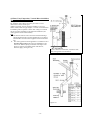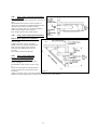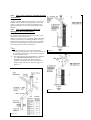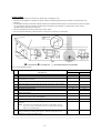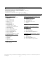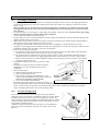
1
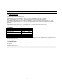
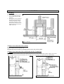
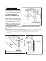
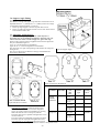
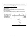
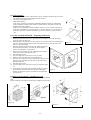
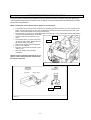
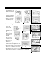
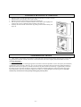
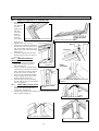
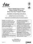
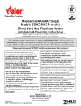
DIRECT VENT GAS FIREPLACE HEATER
MODEL 534 XAN (Natural Gas)
MODEL 534XAP (Propane)
Installation and Owner’s Manual
Please read this manual before installing and operating this heater.
This manual should remain with the homeowner.
WARNING: If the information in these instructions is not
followed exactly, a fire or explosion may result causing
property damage, personal injury or loss of life.
This appliance may be installed in an
aftermarket permanently located,
manufactured (mobile) home, where not
prohibited by local codes.
The appliance is only for use with the type of
gas indicated on the rating plate. This
appliance is not convertible for use with other
gases, unless a certified kit is used.
- Do not store or use gasoline or other flammable
vapors and liquids in the vicinity of this or any
other appliance.
-WHAT TO DO IF YOU SMELL GAS
•
•
Do not try to light any appliance.
Do not touch any electrical switch: do not use
any phone in your building.
• Immediately call your gas supplier from a
neighbor’s phone. Follow the gas supplier’s
instructions.
• If you cannot reach your gas supplier, call the
fire department.
Installation and service must be performed by a
qualified installer, service agency or the gas
supplier.
Massachusetts: the piping and the final gas
connection must be performed by a licensed
plumber or gas fitter in the State of
Massachusetts
This appliance is a domestic room heating
appliance. It must not be used for any other
purpose such as drying clothes etc.
This appliance is suitable for installation in a bedroom
or bed sitting room.
Manufactured by
MILES INDUSTRIES LTD.
British Columbia, Canada
Vous pouvez vous procurer un exemplaire en langue Française de cette brochure chez votre
marchand.
4000307-01
CONTENTS
1.
2.
SAFETY INFORMATION....................................................................................................................................................................3
OPTIONS................................................................................................................................................................................................4
2.1.
Appliance styles .............................................................................................................................................................................4
2.2.
Optional outer trims ......................................................................................................................................................................4
2.3.
Additional optional features .........................................................................................................................................................4
2.4.
Venting options ..............................................................................................................................................................................4
3. GENERAL ..............................................................................................................................................................................................6
3.1.
Approvals & codes.........................................................................................................................................................................6
3.2.
Ratings............................................................................................................................................................................................6
3.3.
Wall Thickness...............................................................................................................................................................................6
4. LOCATION ............................................................................................................................................................................................7
4.1.
Framing ..........................................................................................................................................................................................7
4.2.
Rear Vent Connection. Flat on Wall ............................................................................................................................................7
4.3.
Rear Vent Connection. Flat on Wall with Snorkel Termination ...............................................................................................7
4.4.
Rear Vent Connection, Vertical Vent Rise with Horizontal Rear Termination .......................................................................8
4.5.
Rear Vent Connection, Vertical Vent Rise with Horizontal Snorkel Termination ..................................................................8
4.6.
Corner Location, Rear Vent Connection, Horizontal Vent Run Only ......................................................................................9
4.7.
Corner Location, Rear Vent Connection, Vertical Rise, Horizontal Termination...................................................................9
4.8.
Rear Vent Connection, Vertical Rise, Through the Roof Termination.....................................................................................9
4.9.
Rear Vent Connection, Vertical Rise with Offset, Through the Roof Termination ............................................................... 10
4.10.
Top Vent Connection, Horizontal Rear Termination............................................................................................................... 11
4.11.
Top Vent Connection, Horizontal side termination.................................................................................................................. 12
4.12.
Top Vent Connection, Horizontal Side or Rear Snorkel Termination.................................................................................... 12
4.13.
Top Vent Connection, Corner Location, Horizontal Termination, 45° Pipe Run.................................................................. 12
4.14.
* ........................................................................................................ 13
Top Vent Connection, Offset and Through the Roof Termination* ..................................................................................... 13
Top Vent Connection, Through the Roof Termination
4.15.
4.16.
Vent Location............................................................................................................................................................................... 14
5. SUPPLY GAS ....................................................................................................................................................................................... 15
6. PACK CONTENTS.............................................................................................................................................................................. 15
7. APPLIANCE PREPARATION........................................................................................................................................................... 17
7.1.
Window Removal......................................................................................................................................................................... 17
7.2.
Ignition Spark Check .................................................................................................................................................................. 17
7.3.
Rear Vent Outlet positioning ...................................................................................................................................................... 17
7.4.
# 817VAK Pipe Adapter Fitting ................................................................................................................................................. 17
7.5.
Top heat shield & Stand-off Fitting ........................................................................................................................................... 18
7.6.
Support Angle Fitting.................................................................................................................................................................. 19
7.7.
Attaching Air Restrictors............................................................................................................................................................ 19
7.8.
Attaching Rear Ceramic Support............................................................................................................................................... 20
7.9.
Attaching to the Framing ............................................................................................................................................................ 20
8. INSTALLATIONS WITH HORIZONTAL TERMINATION – INSTALLING TO WALL ........................................................ 21
8.1.
Flat On Wall Installations With Valor #551DVK Terminal .................................................................................................... 21
8.2.
Wall Opening ............................................................................................................................................................................... 22
8.3.
Valor Terminal #551DVK - Preparing Wall Plates .................................................................................................................. 22
8.4.
Dura-vent Terminals – Installing to wall................................................................................................................................... 22
9. INSTALLATIONS WITH THROUGH THE ROOF VERTICAL TERMINATION.................................................................... 23
10. REMOTE CONTROL INSTALLATION ......................................................................................................................................... 24
11. GAS SUPPLY INSTALLATION & AERATION SETTING .......................................................................................................... 25
11.1.
Gas Supply Installation ............................................................................................................................................................... 25
11.2.
Aeration Setting Check ............................................................................................................................................................... 25
12. CERAMIC FUEL BED INSTALLATION........................................................................................................................................ 26
12.1.
Ceramic Walls Installation ......................................................................................................................................................... 26
12.2.
Ceramic Logs Installation ........................................................................................................................................................... 26
13. WINDOW REFITTING & CHECKING .......................................................................................................................................... 27
14. OPERATION CHECKS ..................................................................................................................................................................... 27
15. FRONT INSTALLATION .................................................................................................................................................................. 28
15.1.
Additional Optional 3 or 4 Sided Trims..................................................................................................................................... 28
15.2.
#601SFB Standard Metal Front ................................................................................................................................................. 28
15.3.
#602CFB Cast Iron Front ........................................................................................................................................................... 28
16. OWNERS INFORMATION ............................................................................................................................................................... 29
16.1.
Operating Your Fire.................................................................................................................................................................... 29
16.2.
Cleaning........................................................................................................................................................................................ 30
16.3.
Checks........................................................................................................................................................................................... 32
16.4.
Servicing ....................................................................................................................................................................................... 32
16.5.
General servicing ......................................................................................................................................................................... 32
-2-
1. SAFETY INFORMATION
WARNING: Do not operate the appliance with the
glass front removed, cracked, or broken. Replacement
of the glass should be done by a licensed or qualified
service person.
(The whole window unit may be temporarily removed
by the owner for cleaning the interior of the firebox,
etc.)
Only the authorized Valor replacement window unit
listed in the repair parts booklet must be fitted - never
use substitutes.
If the glass is damaged, search inside and adjacent to
the appliance for any glass fragments.
Due to high temperatures, the appliance should be
located out of traffic and away from furniture and
draperies.
Children and adults should be alerted to the hazards
of high surface temperatures and should stay away to
avoid burns or clothing ignition.
Young children should be carefully supervised when
they are in the same room as the appliance.
Clothing or other flammable material should not be
placed on or near the appliance.
This appliance must be installed and repaired by a
qualified service person. The appliance should be
inspected before use and at least annually by a
professional service person. More frequent cleaning
may be required due to excessive lint from carpeting,
bedding material, etc. It is imperative that control
compartments;
burners
and
circulating
air
passageways of the appliance are kept clean.
Keep curtains, clothing, furniture, and other
flammable materials a safe distance from all parts of
the appliance and its vent system.
Keep the appliance area well clear and free from
combustible materials, gasoline and other flammable
vapors and liquids.
Never attempt to burn paper or any other material in
the appliance.
The venting terminal must not be recessed into a wall
or siding.
The vent terminal on the outside wall must be kept
free from obstructions. No objects should be placed
within 2 feet (60cm) of the vent terminal. The terminal
is hot during operation and requires a guard if it is
accessible to any person. An approved Valor guard is
available from your dealer.
During extreme weather conditions ensure that the
vent outlet is free from ice and snow before attempting
to light.
Do not use this appliance if any part has been under
water. Immediately call a qualified service technician
to inspect the appliance and to replace any part of the
control system and any gas control which has been
under water.
NOTE
When operating your new fireplace for the first time, some vapors may be released due to the burning of curing compounds
used in the manufacture of the appliance. They may cause a slight odor and could cause the flames to be the full height of the
firebox, or even slightly higher, for the first few hours of operation. It is also possible that these vapors could set off any
smoke detection alarms in the immediate vicinity. These vapors are quite normal on new appliances and are totally harmless
but you may wish to open windows into the room to reduce the vapor/odor build up. After a few hours use the vapors will
have disappeared and the flames will be at their normal height.
During the first hour of use, the ceramic firebox walls may go a smoky color. This is not soot. It is a temporary effect lasting
only while the ceramic material becomes stabilized. The walls will revert to their initial color after your fire has been used for
one or two hours.
-3-
2. OPTIONS
Heater engine unit #534XAN is used with all natural gas
installations.
Heater engine unit #534XAP is used with all propane
installations.
2.1. Appliance styles
Standard metal front. Black – Kit #601SFB
Cast iron front. Black – Kit #602CFB.
One of the above kits must be used with each
installation.
2.2. Optional outer trims
Kit #603FSK
3-sided Black –
3-sided Champagne – Kit# 604FSK
Kit #605FSK
4-sided Black –
4-sided Champagne – Kit# 606FSK
2.3. Additional optional features
Circulating fan
Natural Gas
Conversion kit
Having two speeds and
temperature control, it is
designed to boost the natural
convection process through the
appliance. It may be fitted
before the fireplace is installed
or retrofitted at a later date –
Kit #555CFK.
For conversion from propane to
natural gas – Kit #607NGK.
Intended primarily for post
installation conversion in areas
where natural gas was not
available at the time of initial
installation.
-4-
2.4. Venting options
2.4.1.
Direct vent installations
One or more of the accessories listed below must be used
for each installation. See the “Location” section of this
manual.
Kit#
551DVK Valor horizontal terminal kit provides up
to 26” (66cm) horizontal run. Complete
with wall plates and clearance shield
approved for a maximum 14” (36cm)
when fully concealed in a combustible
wall.
817VAK Adapter for Dura-vent pipes
Dura-vent DV GS horizontal square
984
terminal cap
Dura-vent DV GS wall thimble kit
942
45° Dura-vent DV GS elbow
945B
90° Dura-vent DV GS elbow
990B
6” Dura-vent DV GS pipe length
908B
9” Dura-vent DV GS pipe length
907B
12” Dura-vent DV GS pipe length
906B
24” Dura-vent DV GS pipe length
904B
36” Dura-vent DV GS pipe length
903B
48” Dura-vent DV GS pipe length
902B
Adjustable 11”-145/8” Dura-vent DV GS
911B
pipe length
Dura-vent DV GS snorkel termination
981
unit – 36” rise
Dura-vent DV GS snorkel termination
982
unit – 14” rise
Dura-vent DV GS high wind vertical
991
termination cap
Dura-vent DV GS round ceiling support
940
Dura-vent DV GS cathedral ceiling
941
support box
Dura-vent DV GS ceiling fire stop
963
Dura-vent DV GS adjustable roof
943
flashing. Roof pitch 0/12 – 6/12
Dura-vent DV GS steep roof flashing.
943S
Roof pitch 7/12 – 12/12
Dura-vent DV GS storm collar
953
Dura-vent DV GS wall strap
988
Terminal Guard
835TG
Mantle depth “A”
Mantle clearance “B”
1”
(25mm)
7”
(178mm)
2”
(51mm)
8”
(203mm)
3”
4”-5”
(76mm) (102mm- 127mm)
9”
10”
(229mm)
(254mm)
6”
(152mm)
11”
(279mm)
7”
8”–12”
(178mm) (203mm-305mm) max.
12”
14”
(305mm)
(356mm)
Figure 1 Major dimensions & clearances without optional trims (Shown with #601SFB Front)
3 sided trims
4 sided trims
Figure 2 #601SFB Front with optional trims
3 sided trims
4 sided trims
Figure 3 #602CFB Front with optional trims
-5-
3. GENERAL
3.1. Approvals & codes
These appliances are certified by C.S.A. for use in Canada and the USA. These appliances are for installation directly venting
through an outside wall or through the roof.
Model 534XAN is for use with natural gas.
Model 534XAP is for use with propane. It can be converted for use with natural gas with kit #607NGK.
These appliances comply with CGA P.4.1, Testing method for measuring annual fireplace efficiencies.
The installation must conform with local codes or, in the absence of local codes with the National Fuel Gas Code, ANSI
Z223.1or the Canadian installation code CAN/CGA-149. Only qualified licensed or trained personnel should install these
appliances.
These appliances, when installed, must be electrically grounded in accordance with local codes or, in the absence of local
codes, with the National Electrical Code, ANSI/NFPA 70 or the Canadian Electrical Code, CSA C22.1.
3.2. Ratings
534XAN
534XAP
Model
Gas
Natural
Propane
Altitude (Ft)
0-4500 1
Input Max. (Btu/h)
24,000
24,000
Input Min (Btu/h)
6,500
13,000
Manifold pressure (in.w.c.)
3.8-4.2
9.3-9.7
Min. Supply pressure (in. w.c.)
5.0
11.0
Max. Supply pressure (in. w.c.)
10.5
14.0
1
Tested to CAN/CGA - 2.17 Gas fired appliances for use at high altitudes. In the USA, installations may require deration over
2000ft - Check local codes.
3.3. Wall Thickness
The vent system (when horizontally terminated) is approved to pass through combustible wall construction of up to 14”
(36cm) thick.
A non-combustible wall can be any thickness up to the maximum horizontal run of vent pipe allowed for the particular
installation – See section 4.
-6-
4. LOCATION
4.1. Framing
The framing dimensions are shown in figure 4.
• A non-combustible hearth is
not necessary in front of this
appliance.
• Note that the unit is installed at
the framing stage and fixed to
framing using support angles
(see figures 27 and 31). Wall
finish is then installed over the
support angles up to the black
frame on the unit
This is the framing
width.
Wall finish to
32 3/16” wide.
Figure 4 Framing
4.2. Rear Vent Connection. Flat on Wall
See figure 5.
Requires standard vent kit #551DVK only.
The horizontal vent run cannot be extended by the use of any vent accessory pipes.
4.3. Rear Vent Connection. Flat on Wall with Snorkel Termination
See figure 6.
For use on horizontal installations where the outsides ground level is too close to the standard terminal. Adapter #817VAK, a
Dura-vent pipe length and snorkel termination #981 or #982 will be required (See vent options section of this manual).
Figure 6 Rear vent. Flat on wall with Snorkel
Figure 5 Rear vent. Flat on wall
-7-
4.4. Rear Vent Connection, Vertical Vent Rise
with Horizontal Rear Termination
See figure 7.
Can be used with either #551DVK standard vent kit or #984
Dura-vent terminal cap and accessories.
Adapter #817VAK, two 90° vent elbows #990B and Duravent pipe lengths will be required.
(See venting options section of this manual).
The location requirements are shown in the table and graph
below and figure 7.
Minimum Maximum
A: From floor to top of
4ft 3½”
9ft 3½”
vent duct
(131cm)
(283cm)
B: Frame front face to
12ft 5½”
outside wall
(380cm)
C: Frame front face to
2ft 5½”
inside wall
(75cm)
D: Vertical pipe run
12”
6ft
between elbows
(30.5cm)
(183cm)
E1+E2: Total horizontal
10ft
pipe run including
(305cm)
terminal pipe but
With no
excluding adapter and
elbows in
elbows
horizontal
run
F: Clearance to
1”
combustible materials
(12.7cm)
above horizontal pipe run
inside building (Outside
wall shields/thimbles)
G: Clearance to
15/16”
combustible materials
(3.3cm)
below horizontal pipe run
H: Clearance to
2”
combustible materials all
(5.1cm)
round vertical pipe run
and at sides of horizontal
pipe run
Figure 7 Rear vent, vertical rise, rear termination
For installations with a horizontal rear termination, the
combination of horizontal and vertical vent pipes must be
within the allowed area shown in Graph 1. A minimum
vertical pipe run of 12” is necessary.
Graph 1
Example a: If a vertical rise of 3ft is required, the
horizontal run must not be more than 7ft 9”.
Example b: If a horizontal run of 3ft 6” is required, the vertical run must be at least 1ft 9”.
If the horizontal pipe run is redirected using a further 90ºelbow, the maximum total horizontal run allowed is reduced
by 3ft. to 7ft. Redirection using 45º elbows reduces the maximum total horizontal run by 18” per elbow.
4.5. Rear Vent Connection, Vertical Vent Rise with Horizontal Snorkel Termination
For “semi-basement” situations where a snorkel accessory alone does not raise the termination sufficiently above ground
level. The dimensional requirements in section 4.4, figure 7, and graph 1 apply.
Adapter #817VAK, two 90º vent elbows #990B, Dura-vent pipe lengths and a Dura-vent snorkel termination will be required.
#942 Dura-vent thimble kit may also be necessary. (See venting options section of this manual)
-8-
4.6. Corner Location, Rear Vent
Connection, Horizontal Vent Run Only
See figure 8.
Can be used with either #551DVK standard vent kit or
#984 Dura-vent terminal cap and accessories. Adapter
#817VAK and 45º Dura-vent elbow # 945B will be
required. (See venting options section of this manual.)
4.7. Corner Location, Rear Vent
Connection, Vertical Rise, Horizontal
Termination
See figure 9.
Can be used with either #551DVK standard vent kit or
#984 Dura-vent terminal cap and accessories. Adapter
#817VAK, two 90º Dura-vent elbows #990B and Duravent pipe lengths will be required. (See venting options
section of this manual).
All the vent pipe dimensional limits are as section 4.4.
4.8. Rear Vent Connection, Vertical Rise,
Through the Roof Termination
Figure 8 Corner location, rear vent connection, horizontal vent run
See figure 10.
Adapter #817VAK, one 90º-vent elbow #990B, Dura-vent pipe lengths, a vertical vent terminal and roof flashing will be
required. Various other ceiling or roof items may be necessary depending on the particular installation (See venting options
section of this manual).
Note
1. The distance from the roof to the lowest terminal discharge opening depends on the roof pitch and must be in accordance
with the Dura-vent instructions supplied with the termination unit.
2. The venting system for these appliances is considered to be a Special Venting System. The rule in the Installation Code
CAN/CGA–B149 requiring a minimum vent height of 2ft above any portion of a building within 10ft does not,
therefore, apply.
Figure 9 Corner location, rear vent connection, vertical rise,
horizontal vent run
-9-
Figure 10 Rear vent connection, through the roof
termination
4.9. Rear Vent Connection, Vertical Rise with Offset,
Through the Roof Termination
See figure 11.
For situations where offset is necessary in an attic to avoid
obstructions or allow useful space.
Adapter #817VAK, one 90º vent elbow #990B, two 45º vent
elbows #945B, Dura-vent pipe lengths, a vertical vent terminal and
roof flashing will be required. Various other ceiling or roof items
may be necessary depending on the particular installation (See
venting options section of this manual).
Note
1. The distance from the roof to the lowest terminal discharge
opening depends on the roof pitch and must be in accordance
with the Dura-vent instructions supplied with the termination
unit.
2. The venting system for these appliances is considered to be a
Special Venting System. The rule in the Installation Code
CAN/CGA–B149 requiring a minimum vent height of 2ft
above any portion of a building within 10ft does not,
therefore, apply. (See figure 11a)
Figure 11 Rear vent connection, vertical rise with
offset, through thru roof termination
Figure 11a
- 10 -
4.10. Top Vent Connection, Horizontal Rear
Termination
See figure 12.
Can be used with either #551DVK standard vent kit or #984 Dura-vent
terminal cap and accessories.
Adapter #817VAK, one 90° vent elbow #990B and Dura-vent pipe
lengths will be required.
(See venting options section of this manual).
The location requirements are shown in the table and graph below and
figure 12.
A: From floor to top of
vent duct
B: Frame front face to
outside wall
C: Frame front face to
inside wall
D: Vertical pipe run
between elbows
E: Total horizontal pipe
run from elbow (including
terminal pipe)
F: Clearance to
combustible materials
above horizontal pipe run
inside building (Outside
wall shields/thimbles)
G: Clearance to
combustible materials
below horizontal pipe run
H: Clearance to
combustible materials all
round vertical pipe run
and at sides of horizontal
pipe run
Minimum
3ft 79/16”
(111cm)
16”
(75cm)
6”
(15.2cm)
-
1”
(12.7cm)
Maximum
9ft 19/16”
(278cm)
11ft 4”
(345cm)
6ft
(183cm)
10ft
(305cm)
With no
elbows in
horizontal
run
-
15/16”
(3.3cm)
-
2”
(5.1cm)
-
Figure 12
For installations with a horizontal rear termination, the combination Graph 2
of horizontal and vertical vent pipes must be within the allowed area
shown in Graph 2. A minimum vertical pipe run of 6” is necessary.
Example a: If a vertical rise of 2ft 6” is required, the horizontal run
must not be more than 8ft”.
Example b: If a horizontal run of 3ft 6” is required, the vertical run
must be at least 1ft 3”.
The horizontal vent pipe run may be redirected by using
elbows up to a total of 180º but the maximum horizontal
run (E in figure 5 & graph 1) is reduced by 18” for every
45º. For example if two 90º elbows are used as in figure
13 the maximum horizontal run is reduced by 3ft per
elbow –
Total reduction = 6ft.
- 11 -
Figure 13
4.11. Top Vent Connection, Horizontal
side termination
The vent pipe dimensional requirements in section 4.10
apply.
The minimum floor location is shown in figure 14.
Can be used with either #551DVK standard vent kit or
#984 Dura-vent terminal cap and accessories.
Adapter #817VAK, one 90° vent elbow #990B and
Dura-vent pipe lengths will be required.
(See venting options section of this manual).
4.12.
Top Vent Connection, Horizontal
Figure 14
Side or Rear Snorkel Termination
The dimensional requirements in sections 4.10
and 4.11 apply.
Adapter #817VAK, one 90° vent elbow
#990B, a Dura-vent snorkel termination and
Dura-vent pipe lengths will be required.
#942 Dura-vent thimble kit may also be
necessary.
(See venting section of this manual).
4.13. Top Vent Connection,
Corner Location, Horizontal
Termination, 45° Pipe Run
The vent pipe dimensional requirements in
section 4.10 apply.
The minimum corner location is shown in fig.
15.
Can be used with either #551DVK standard
vent kit or #984 Dura-vent terminal cap and
Figure 15
accessories.
Adapter #817VAK, one 90° vent elbow #990B
and Dura-vent pipe lengths will be required. (See venting section of this manual).
- 12 -
4.14.
Top Vent Connection, Through the Roof
Termination*
See figure 16.
Adapter #817VAK, Dura-vent pipe lengths, a vertical vent
terminal, and roof flashing will be required. Various other
ceiling or roof items may be necessary depending on the
particular installation (See venting options section of this
manual).
4.15.
Top Vent Connection, Offset and
Through the Roof Termination*
See figure 17.
For situations where offset is necessary in an attic to avoid
obstructions or allow useful space.
Adapter #817VAK, two 45° vent elbows #945B, wall straps,
a vertical vent terminal, roof flashing and Dura-vent pipe
lengths will be required. Various other ceiling or roof items
may be necessary depending on the particular installation
(See venting options section of this manual).
*Note
1. The distance from the roof to the lowest terminal
discharge opening depends on the roof pitch and must be
in accordance with the Dura-vent instructions supplied
with the termination unit.
2. The venting system for these appliances is considered
to be a Special Venting System. The rule in the
Installation Code CAN/CGA–B149 requiring a
minimum vent height of 2ft above any portion of a
building within 10ft does not, therefore, apply. (see
figure 17a)
Figure 16
4.16.
Figure 17
Figure 17a
- 13 -
Vent Location
• The vent terminal must be located on an outside wall or through the roof.
• This direct vent appliance is designed to operate when an undisturbed airflow hits the outside vent terminal from any
direction.
• The minimum clearances from this terminal that must be maintained when located on an outside wall are shown in figure
18. Any reduction in these clearances could result in a disruption of the airflow or a safety hazard. Local codes or
regulations may require greater clearances.
• The vent terminal must not be recessed into a wall or siding.
• The vent terminal should be positioned where it will not be covered by any snowdrifts.
Fig. 18 Vent terminal locations
KEY
A
B
C
D
E
F
G
H
I
J
K
L
M
Note:
VENT TERMINAL LOCATIONS - MINIMUM DISTANCES
See figure 18
Clearance above grade, verandah, porch, deck or balcony
Clearance to window or door that may be opened
Clearance to permanently closed window (recommended to prevent
condensation on window)
Vertical clearance to ventilated soffit located above the terminal within a
horizontal distance of 2 feet (60 cm) from the center-line of the terminal
Clearance to unventilated soffit
Clearance to outside corner
Clearance to inside corner
Horizontal clearance to center-line of meter/regulator assembly located
below the terminal
Clearance to service regulator vent outlet
Clearance to non-mechanical air supply inlet to the building or the
combustion air inlet to any other appliance
Clearance to a mechanical air supply inlet
Clearance above paved sidewalk or a paved driveway located on public
property.
Note: A vent must not terminate directly above a sidewalk or paved
driveway, which is located between two single-family dwellings
and serves both dwellings.
Clearance under a verandah, porch, deck or balcony
Only permitted if veranda, porch, deck, or balcony is fully open on a
minimum of 2 sides beneath the floor.
Local codes and regulations may require different clearances.
- 14 -
MINIMUM CLEARANCE
Ins
Cms
12
30
12
30
12
30
18
46
12
12
12
36
30
30
30
90
72
12
180
30
72
84
180
210
12
30
5. SUPPLY GAS
Heater engine unit #534XAN is used with all natural gas installations.
Heater engine unit #534XAP is used with all propane installations.
The supply pressure must be between the limits shown in section 3.2 of this manual.
The supply connection is 3/8’’NPT.
The opening for the gas supply line is at the rear left corner of the appliance.
6. PACK CONTENTS
See figure 19
#534XAN or #534XAP Engine unit
1 Appliance engine unit fitted with window
1 Ceramic ash bed
7 Ceramic logs
1 Firebox ceramic rear wall
2 Firebox ceramic sidewalls
1 Port cover
2 Frame side fixing brackets
1 Ash bed rear support
2 Restrictor plates type “A”
2 Restrictor plates type “B”
2 Restrictor plates type “C”
1 Gas inlet pipe connection adapter
1 Top heat shield panel with blanking plate
1 Frame top support angle
2 Stand-off brackets
2 Screws for wall switch plate
4 Screws for frame side fixing brackets
2 Screws for top heat shield panel
3 Screws for frame top support angle
6 Screws for standoff brackets
2 Screws for vent fixing
4 Woodscrews for fixing appliance to studding
1 Deluxe remote control
#601SFB Standard metal front (Alternative)
1 Upper louver unit
1 Lower louver unit
2 Side channels
2 Hinge studs
2 Hinge spacers
2 Magnet counter plates
#551DVK Standard horizontal through the wall vent
kit (Alternative to Dura-vent unit)
1 Vent pipe & terminal unit
2 Wall plates
2 Wall shields (Supplied flat)
12 Thread cutting screws
1 Styrofoam cutting support do-nut
8 Wood screws
8 Wall plugs
#555CFK Circulating fan kit (Additional option)
Details are with the kit
#603FSK Black or #604 Champagne Additional
optional 3 sided trims
1 Top trim
2 Side trims
2 Trim fixing brackets
2 Corner connection plates
8 Grub screws for corner connections
10 Screws for side trims & engine attachment
#605FSK Black or #606FSK Champagne Additional
optional 4 sided trims
2 Top & bottom trims
2 Side trims
2 Trim fixing brackets
4 Corner connection plates
16 Grub screws for corner connections
10 Screws for side trims & engine attachment
#602CFB Cast iron front (Alternative)
1 Top casting unit
1 Bottom casting unit
Take care when removing the contents from the packaging to prevent damage. Check that all the contents are in the packs and
are undamaged.
- 15 -
- 16 -
7. APPLIANCE PREPARATION
7.1. Window Removal
See figure 20.
• Turn the top three spring loaded window bolts through 900 to release the window
from the firebox.
• Remove the bottom three spring-loaded window bolts.
• Detach the chain from the top right corner of the window.
• Carefully lift the window away. Keep the window and bolts in a safe place.
7.2. Ignition Spark Check
The pilot burner and electrode unit is at the left end of the burner.
Push in the lighting knob and turn counter-clockwise through the “IGN” position to
“PILOT”. A spark should flash across from the pilot electrode to the pilot burner shield.
See figure 21.
Figure 20 Window removal
Figure 21 Ignition spark check
7.3. Rear Vent Outlet positioning
If installing with top vent outlet ignore this stage
See figure 22
1. Remove the rear outlet cover plate and seal by unscrewing 12 screws.
Keep the seal and plate for fitting to the top.
2. Remove the top outer vent collar and seal by unscrewing 12 screws.
3. Remove the top inner vent collar and seal by unscrewing 8 screws.
4. Locate the inner collar and seal inside the rear outlet opening. Secure the
inner collar with 8 screws.
5. Fit the outer collar over inner collar. Loosely fit the 12 screws. Place the
Dura-vent adapter #817VAK or Valor terminal unit #551DVK over the
collars to check alignment. Tighten the 12 screws to secure the outer
collar.
6. Fit the cover plate and seal (Removed from the rear) to the top vent
opening with 12 screws.
7.4. # 817VAK Pipe Adapter Fitting
If installing flat on wall with Valor terminal unit #551DVK ignore this
stage.
See figure 23.
1. Fit the Dura-vent adapter #817VAK over the appliance vent collars
pushing on firmly.
2. For rear vent outlet connection, align the adapter so that the seam on
horizontal Dura-vent pipes is not at the bottom – Check by temporarily
fitting a Dura-vent pipe.
3. Drill through the adapter outer tube and appliance outer collar for #6
screws. See figure 40. Make sure that the drill does not penetrate the
inner tubes.
4. Secure the adapter to the outer collar with two #6 thread cutting screws
supplied.
- 17 -
Figure 22
Figure 24 Heat shield
(Shown for top vent outlet)
Figure 23
7.5. Top heat shield & Stand-off Fitting
See figures 24 & 25.
1. If installing appliance with top vent outlet remove the plate covering
the vent hole in the top heat shield by unscrewing four screws. If
installing with rear vent outlet, the plate must remain covering the
hole.
2. Remove the screws at the top rear corner of the case sides.
3. If top vent outlet, locate the heat shield over the vent pipe adapter.
4. Support the front of the shield on the two angle supports.
5. Secure the shield to the case sides by refitting the two screws at the top
rear corners and by two screws from the pack fitted near the front.
6. Bend the two top rear stand-offs and fit to the heat shield with three
screws each – see figure 26.
Figure 25 Top & rear Stand-offs
- 18 -
7.6. Support Angle Fitting
See figure 26
The distance from the wall angles to the front face of the heater case is
adjustable between 3/8” (10mm) and 13/16” (30mm) to allow for a range
of wall finish material thickness (e.g. tile etc).
1. Fit the top angle support to the case top with three screws.
2. Fit the two side angle supports with two screws each. Fit the screws
from inside the heater case.
7.7. Attaching Air Restrictors
No restrictors are required for appliances, which only have a
horizontal vent, run. If installing an appliance, which has rear vent
outlet connection and no vertical vent pipe rise, ignore this stage.
There are three types of restrictor supplied with each #534 engine unit.
They are identified in figure 27.
Type “A” is for horizontal vent termination.
Types “B” & “C” are for through-the-roof termination.
The restrictors cover part of the openings in the firebox rear wall ports –
Figure 26 Support angles
See figure 28.
The correct restrictors to be fitted for each type of installation are
shown in the table below.
Figure 27 Restrictor identification
Vent
terminal
Horizontal
through
wall with
vertical rise
Figure 28 Restrictor locations
Appliance
vent outlet
Top
Rear
To fit type “A” restrictors remove the center screws
from the rear ports and fit the restrictors using these
screws. To set the restrictors at maximum port opening,
Vertical
Top or rear
slacken the bottom screws in the ports, slide the
through roof
restrictors down as far as possible and tighten the screws
over the restrictors.
To set the restrictors at minimum port opening, slide the
restrictors up as far as possible and tighten the screws.
To fit types “B” or “C” restrictors remove the top and
bottom screws from the rear ports and fit the restrictors using these screws.
- 19 -
Vertical
vent
pipe
run
Use
restrictor
type
Port
opening
set at
Less than 3ft
(91cm)
From 3ft
(91cm) to 6ft
(183cm)
Less than 3ft
6” (107cm)
From 3ft 6”
(107cm) to
6ft (183cm)
Less than
20ft (6.1m)
From 20ft
(6.1m) to
40ft (12.2m)
A
Maximum
A
Minimum
A
Maximum
A
Minimum
B
Not
applicable
C
7.8. Attaching Rear Ceramic Support
Fit the rear ceramic support to the firebox back
panel with three screws. See figure 29.
7.9. Attaching to the Framing
1.
2.
3.
Place the heater in position in the framing.
Secure the side support angles to the side
studding through two holes each side with the
woodscrews supplied. The top support angle
should abut the wall finish but is not fixed to
the framing.
Check the wall finish requirements with the
homeowner. If necessary, adjust the position
of the heater so that the distance from the
front of the heater case to the angles is
suitable for the thickness of the wall finish
(e.g. tile, etc.) – see figure 30
Figure 29 Rear ceramic support
Figure 30 Adjustment for wall finish
- 20 -
8. INSTALLATIONS WITH HORIZONTAL TERMINATION – INSTALLING
TO WALL
See section 4 for full range of horizontal termination applications.
8.1. Flat On Wall Installations With Valor #551DVK Terminal
1.
Cut the vent terminal pipe unit to size. See figure 31.
Important! The drain hole must be clearly outside the wall.
a) Measure the wall thickness.
b) Add distance from case rear to wall.
c) Measure this total length along the vent unit from where the termination cap joins the main terminal pipes. Mark the
unit.
d) Insert the Styrofoam support ring and push it as close as possible to the marked position.
e) Cut the vent tubes squarely to length.
f) Make sure that all Styrofoam is removed from the vent unit after cutting.
2. Free the appliance from the frame studding by removing the four screws inside the firebox securing the side angles (See
figure 30). Slide the appliance forward to allow the terminal to be fitted.
3. Fit the vent unit fully over the appliance
inlet and outlet collars pushing on firmly.
Make sure that the drain hole is at the
bottom – the seam will be through the
notch in the wall plates – See figure 34.
4. Drill through the terminal outer tube and
appliance outer collar for #6 screws. See
figure 31. Make sure that the drill does
not penetrate the inner tubes.
5. Secure the terminal to the outer collar
with two #6 thread cutting screws
supplied (Fig. 31).
Figure 31
- 21 -
8.2. Wall Opening
•
•
•
Where applicable, fit all the required Dura-vent DV GS pipes and elbows up to the wall.
See the Dura-vent instructions supplied with the sections.
Check the wall opening position.
Make Wall Opening.
If the wall is constructed of solid non-combustible materials and has no combustible
surface cladding (including wood) inside or outside then the wall plates or Dura-vent
thimbles will not be required.
If the wall has combustible material, mark the wall for a 10”x10” square. If the wall is
totally non-combustible (e.g. masonry block or concrete) mark for a 7” circular hole. In
both cases, the center of the hole should line up with the centerline of the horizontal
vent.
8.3. Valor Terminal #551DVK - Preparing Wall Plates
The wall plates are not used for 7” hole in non-combustible walls.
1. Bend the wall shields and screw to the inside of the wall plates with 6 thread cutting
screws per plate. See figure 32.
2. Bend the inner wall plate tab as shown in figure 34 so that the seam on the terminal tube
will pass clearly through the plate with the wall shield at the top. Place the inner wall
plate over the terminal unit.
3. Slide the appliance/terminal into the wall. Make sure that the
drain hole is at the bottom – the seam will be through the
notch in the wall plates – See figure 34.
4. Slide the inner wall plate up to the wall. Mark the four holes
for the wall screws. Slide the plate away.
5. Drill and plug the wall.
6. Screw the plate to the wall with 4 screws provided.
7. Bend the outer wall plate tab as shown in figure 34.
8. Place the outer wall plate over the terminal unit. Slide the wall
plate up to the wall. Mark the four holes for the wall screws.
Slide the plate away.
9. Drill and plug the wall.
10. Screw the plate to the wall with 4 screws provided. See figure
34.
11. If the appliance was freed from the frame studding, refit with
the four screws inside the firebox securing the side angles.
Figure 33
Position the appliance so that it is suitable for the wall finish
(See figure 30).
8.4. Dura-vent Terminals – Installing to wall
Unless the wall is totally non-combustible, fit Dura-vent wall thimbles
#942.
Install as detailed in the Dura-vent instructions supplied with the pipes.
Figure 33b
Figure 33a
Figure 34
- 22 -
Figure 32
9. INSTALLATIONS WITH THROUGH THE ROOF VERTICAL
TERMINATION
• Check the roof pitch to determine which roof flashing will be needed
- see vent accessories section 2.4.
• The distance from the roof to the lowest terminal discharge opening
(“H” in figure 35) depends on the roof pitch and must be in
accordance with the Dura-vent instructions supplied with the
termination unit.
Note: The venting system for these appliances is considered to be a
Special Venting System. The rule in the Installation Code requiring
a minimum vent height of 2ft above any portion of a building within
10ft does not therefore apply.
• The minimum clearances to combustible materials all round the vent
pipes must be in accordance with the dimensions shown in section 4
of this manual.
• Drop a plumb from the ceiling to the center of the appliance vent
opening. Mark the position on the ceiling. Drill a small hole at the
marked position.
• Determine the position where the vent will pass through the roof. If
directly above the position where it penetrates the ceiling, drop a
plumb from the roof to the small hole in the ceiling and mark the
roof at this spot.
If rafters or other obstructions will prevent a vertical exit or if clear
attic space is desired, the roof outlet can be offset using 45º elbows see fig. 35.
Drill a small hole at the marked position.
• A ceiling fire stop must be installed at the second floor and higher
floors.
A ceiling support should be used below the flat ceiling.
To install the fire stop & support cut and frame a 10” (254mm)
square hole centered on the small hole previously drilled - see fig.
36.
Fig 35 Through the roof installation
• Fit vent accessory elbows and pipe lengths as required
up through ceiling support boxes and fire stops.
If installation includes offset, support the offsetting
pipes every 3 feet (1m) with wall straps (fig. 35).
• Cut a hole in the roof centered on the small hole. The
hole must allow for the minimum clearances to
combustible materials - see section 4.
• Fit pipe lengths through the roof. Fit roof flashing
securing it with roofing nails.
• Fit storm collar and termination cap.
Fig 36 Fire stop hole
- 23 -
10. REMOTE CONTROL INSTALLATION
Caution! Don’t connect the batteries to the remote control receiver until the wires are
connected to the burner control unit, as short circuit could result in destruction of the
electrical components.
When installing the remote please refer to figures 37 and 38 below.
•
•
•
•
•
•
•
Connect the wiring harness to the receiver box, by pushing the wire connector on to the receiver circuit
board. The plug will only go on one way so please ensure that the wires are pointing up and slot in the
board is inline with the tab on the wiring harness plug
Connect wires “A” (with the “L” terminals) to the connectors “B” on the control valve Please note that the
connectors are different sizes, the smaller
one fits to the lower connection on the
“D”
valve.
Connect the wires “C” to the connectors
“B”
“D” on the control valve. (Either wire can
be fitted to either connector).
Remove the remote control receiver lid.
Fit four 1.5V batteries.
Place the remote control receiver on the
“Velcro” pad.
Fit the 9V battery to the handset
transmitter
Remote control operating instructions are on
page 31 of this manual and are supplied with
the remote control kit.
Figure 37 Valve connections
“A”
“C”
Figure 38
- 24 -
11. GAS SUPPLY INSTALLATION & AERATION SETTING
11.1.
Gas Supply Installation
11.2.
Aeration Setting Check
• The gas supply pipe should enter the appliance case through the opening at the rear left side. The supply pipe should be
connected to the appliance gas inlet pipe situated at the left side of the control unit. Supply line connection to the inlet
pipe is 3/8”NPT.
If the circulating fan is to be installed, be aware that the supply pipe run inside the case should be at the same height
as the appliance inlet pipe in order to clear the fan. If intending to fit an internal isolating valve, check that it will be
clear of the fan.
• Use only new black iron or steel pipes or copper tubing if acceptable - check local codes. Note that in USA copper tubing
must be internally tinned for protection against sulfur compounds.
• Unions in gas lines should be of ground joint type.
• The gas supply line must be sized and installed to provide a supply of gas sufficient to meet the maximum demand of the
appliance without undue loss of pressure.
• Sealant used must be resistant to the action of all gas constituents including LP gas. Sealant should be applied lightly to
male threads to ensure excess sealant does not enter gas lines.
• The supply line should include a manual shut-off valve to allow the appliance to be disconnected for servicing.
• A plugged 1/8”NPT tapping must be installed in the line. The tapping must be accessible for test gauge connection and be
immediately upstream of the gas supply connection to the appliance.
• Pressure test the supply line for leaks.
The appliance and its individual shut-off valve must be disconnected from the gas supply piping system during any
pressure testing of that system at test pressures in excess of ½psig (3.5kPa).
The appliance must be isolated from the gas supply piping system by closing its individual manual shut-off valve
during any pressure testing of the gas supply piping system at test pressures equal to or less than ½psig (3.5kPa).
Failure to either disconnect or isolate the appliance during pressure testing may result in regulator or valve damage.
Consult your dealer in this case.
• The minimum supply pressure is given in section 3 of this
manual.
• All piping and connections must be tested for leaks after
installation or servicing. All leaks must be corrected
immediately.
• When testing for leaks:
Make sure that the appliance is turned off.
Open the manual shut-off valve.
Test for leaks by applying a liquid detergent or soap
solution to all joints. Bubbles forming indicate a gas leak.
Never use an open flame to check for leaks.
Correct any leak detected immediately.
Figure 39 Pressure test tapings
• The pressure test tapping locations are shown in figure 39. A
built-in non-adjustable regulator controls the burner manifold pressure. The correct pressure range is shown in the table in
section 3 of this manual. The pressure check should be made with the burner alight and the thermostat at its highest
setting. See lighting instruction section for full operating details.
The air shutter is factory set at an aeration gap that will give optimum
performance for the vast majority of installations. However, in a few unusual
installations performance may be improved by adjusting the aeration. The
need for adjustment should be determined by operating the appliance with the
ceramic fuel effects and window installed. See the “Final checks” section in
this manual for adjustment details.
Adjust the aeration by slackening the aeration plate screw and sliding the
plate. In an extreme circumstance, the plate can be totally removed. See
figure 40.
Figure 40 Aeration setting
- 25 -
12. CERAMIC FUEL BED INSTALLATION
12.1.
1.
2.
3.
Ceramic Walls Installation
Locate the ceramic rear wall
in the channel at back of the
firebox and flat against the
back of the firebox. See
figure 41.
Locate the sidewalls against
the sides of the firebox.
Make sure that they are
behind the raised edges of
the burner module base at
the back corners. See figure
42.
Remove two screws from
under the top front of the
firebox. Using these screws
fit the port cover. See figure
43.
Figure 41 Rear wall
12.2.
1.
2.
3.
4.
5.
6.
7.
Figure 42 Side walls
Figure 43 Port cover
Ceramic Logs Installation
Place the ash bed in
position. The
projections at the
front of the ash bed
locate against the
sloping metal stops
immediately behind
the burner. See figure
Figure 44a
44.
Place wedge piece in
position locating on
the two pins located
in the ash bed. See
figure 44a.
Place the rear log in
position locating the
two pins in the top of
wedge into the holes
in the rear log. See
figure 45.
Place the front log at
Figure 44 Ash bed
the front of the
firebox as shown in figure 46.
Place the right side center log in position locating it
on the two locating pins on the left hand side of the
ash bed with its “nose” resting at the center of the
ash bed as shown in figure 47.
Place the right side center log in position locating on
the two pins on the right hand side of the ash bed
with its nose” resting at the center of the ash bed as
Figure 45 Rear log
shown in figure 48.
Place “branch end” of the cross log on the pin located on the center of the rear log and
the other end in the locating pocket on the left side of the front log as shown in figure
49.
Figure 46 Front log
Figure 47 left centre log
Figure 48 right centre log
Figure 49 Cross log
- 26 -
13. WINDOW REFITTING & CHECKING
1.
2.
3.
4.
5.
Refit the window with the bottom three bolts. The bolts should be screwed in securely.
Refit the chain to the top right corner of the window.
Refit the top three bolts securing by turning them through 90º.
Pull the top of the window forward and release to check that it opens slightly and
returns in the event of a delayed ignition explosion. See figure 50.
Similarly check the bottom of the window by pulling it forward and releasing. See
figure 50.
Figure 50
14. OPERATION CHECKS
• Check ignition, pilot stability, burner flames, and the full range of the thermostat settings using the rotary switch inside
the appliance and all other controls (wall switch, remote hand unit). See owner’s lighting instructions further on in this
manual for full details.
• Aeration adjustment
As described in section 11, for natural gas appliances, the burner aeration is adjustable. For the vast majority of installations,
no adjustment will be necessary. However, in a very few instances, performance may be improved by sliding the shutter to
adjust the aeration by (See figure 46). Evaluate the aeration only after the unit has warmed up – approximately 15 minutes.
Increasing aeration will cause the flame to appear more transparent and blue making the ceramic fuel effects glow more.
Decreasing aeration will cause the flames to appear more yellow or orange making the fuel effects glow less. Too little
aeration may result in black carbon forming and dropping into the firebox.
- 27 -
15. FRONT INSTALLATION
15.1.
1.
2.
3.
4.
Additional Optional 3 or 4 Sided Trims
Slide a corner connection plate into the channels in the top
trim and a side
trim. Butt the
two trims
together. Fit
four grub
screws and
tighten to
secure the
trims and
Figure 51 Trims & corner plate attachment
corner plate.
Figure 52 Trim bracket attachment
See figure 51.
Repeat for the other corner(s).
Attach the two trim fixing brackets to
the side trims with three screws each
side. The brackets must butt up to the
edges of the corner connection plates.
See figure 52.
Attach the complete trim unit to the
firebox with four screws as shown in
figure 53.
15.2. #601SFB Standard
Metal Front
1.
2.
3.
4.
Fit the lower louver unit using the
Figure 53 Trim unit
hinge studs and hinge spacers as
installation
shown in figure 54.
Fix the two adhesive backed magnet
counter plates to the tabs at the firebox
sides, which line up with the magnets
on the lower louver. See figure 54.
Fit the two side channels by hooking
into the openings at the sides of the
firebox as shown in figure 55.
Attach the upper louver by hooking
over the tabs near the top of the firebox
sides. See figure 56.
15.3.
1.
2.
Figure 54 Lower louver & magnet counter plate
installation
#602CFB Cast Iron Front
Figure 55 Side channel
Attach the bottom-casting unit by
installation
hooking over the lower tabs at the
firebox sides. See figure 57.
Attach the top-casting unit by hooking over the four tabs at the firebox
sides as shown in figure 58.
Figure 56 Upper louver installation
Figure 57 Bottom casting installation
Figure 58 Top casting installation
- 28 -
16. OWNERS INFORMATION
Please read the safety information and notes on page 3.
16.1.
Operating Your Fire
The operating instructions are also on a chained plate inside the control access door.
1. For your safety, this appliance is fitted with a flame supervision device, which will shut off the gas supply if, for any
reason, the pilot flames go out. This device incorporates a fixed probe, which senses the heat from the pilot flame. If the
probe is cool, the device will prevent any gas flow unless the burner control knob is kept pushed in at the PILOT position.
See full lighting instructions on next page.
2. The Valorstat Programmable Remote Control
Your Valor Remote Control helps you get the comfort, convenience and aesthetics you want from your Valor Gas Fireplace.
The first thing to do is to set the time:
1. With your left thumb, hold down both the “AUTO” and the “TIMER” button until the temperature symbol flashes.
Let go.
2. Note the digital clock on the bottom right hand corner. The large “up” button (▲) sets the hour; the “down” (▼)
button sets the minutes. Set the time. Note: you must start setting the time while the temperature symbol is flashing.
If it stops flashing, go back to 1.
3. Let go and wait until the flashing stops. The remote tells you the time you set. It also tells you the current
temperature.
The “remote” controls your fireplace in three different ways.
Setting the Temperature
Use this setting when you come in and want to enjoy a certain temperature.
Here’s what you do:
1. Push the “AUTO” button until the temperature reading flashes. Let go.
2. While it is still flashing, push the up and down button to the temperature you want. Let it go.
3. Your Valor will reach that temperature and the remote will check the temperature every five minutes, adjusting the
amount of fuel needed to give you a steady, even heat.
Note: be patient with settings as it can take a few seconds.
Setting the Flame
Use this setting when you want a particular flame level. For instance, you want to watch flames burn at their highest level,
and you don’t mind if the room is too hot.
Here’s what you do:
1. Press either of the large “up” or “down” buttons.
2. The word “man” displays as well as an arrow in the left upper corner. Let go.
3. To raise the flame, press and hold the “up” button until you come to the flame level you want. Let go.
4. To lower the flame, press and hold the down button until you come to the flame you want. Let go.
5. The flame level will remain just as you set it.
Programming Time and Temperature
You can set your Valor to come on before you waken and turn after you leave home and turn on again just before you come
home and turn off after going to bed. You can leave it like this for the heating season.
Here’s what you do:
1. Decide what temperature you want your Valor to be at; also decide what time you want your Valor to turn on and
off; then decide what time you want it to come back on and off in the afternoon or evening. For the first few times
you set the timer, it’s handy to write these times down.
2. Set the temperature (just as you did in the section on “setting the temperature.”
3. Press the “timer” button and hold until “P1*” appears and flashes. Let go. While flashing, push the “up” button to
the hour you want your Valor to turn on in the morning and the “down” to the minute.
4. Press “timer” to P1 (moon) and proceed as in step 3, to turn off time.
5. Press “timer” again, and you get “P2*” to set the time to come back on in the afternoon. Set the time.
6. Press “timer” again to get P2 (moon) to set the time for your Valor to go off in the evening.
7. Do nothing else, and your Valor will give you steady, even heat at the temperatures and times you set.
8. Note: If you want to set your Valor for only 1 time on and off, set P2 for the same times as P1.
9. To temporarily override the timer setting, just press “auto” or “manual”. Press “timer” when you want to go back to
your settings.
3.
When first turned on, the decorative flames will appear predominantly blue. After approximately 15 minutes the flames
will turn yellow.
- 29 -
16.2.
Cleaning
It will be necessary to clean the glass periodically. During startup, condensation, which is normal, forms on the inside of the
glass and causes dust, lint etc. to cling to the glass surface. Initially paint, while curing, may deposit a slight film on the glass.
We therefore recommend that, during the first few weeks of use, the glass is cleaned two or three times with non-abrasive
common household cleaners and warm water. Ammonia based cleaners should not be
used. Subsequently the glass should be cleaned two or three times a season depending
on the circumstances. Do not clean the glass while it is hot.
Always close the window securely before lighting
16.2.1.
To Clean the Inside of the Glass
16.2.2.
Burner
To Clean the Ceramic Fuel Effects, Firebox Walls &
•
Louver Fronts: Lift and unhook the top louver – see figure 59. Lift and unhook
the two side channels – see figure 60. Open the bottom louver – It does not need to be
Figure 59 Louver removal
removed.
•
Cast Iron Fronts: Lift up and unhook the upper casting. The bottom casting does
not need to be removed. See figure 61.
•
Push in the three spring loaded bolts at the top of the window and make a quarter turn so
that the slots in the bolt heads are horizontal. This will release the top of the window. Swing the
top of the window open as far as the chain will allow. The window should be open enough to let
you clean the inside of the glass. See figure 62.
Always securely fasten the window before lighting.
Dust, etc. can be brushed from the ceramic fuel effects and firebox walls after removing the
front unit and completely removing the window.
Dust etc. can also be removed from the burner using a soft brush after removing the ceramic fuel
effects.
• Louver Fronts: Lift and unhook the top louver. Open the bottom louver – It does not need
to be removed. See figure 59.
Cast Iron Fronts: Lift up and unhook the upper casting. Lift up and unhook the
bottom casting. See figure 61.
•
Push in the three spring loaded bolts at the top of the window and make a quarter
turn so that the slots in the bolt heads are horizontal. This will release the top of
the window. See figure 62.
•
Remove the bottom three spring-loaded window bolts. See figure 62.
•
Detach the chain from the top right corner of the window. See figure 62.
•
Carefully lift the window away. Keep the window and bolts in a safe place.
Always completely remove the window before removing the ceramic fuel effects.
When cleaning, make sure that no particles are brushed into the slots in the burner.
Always securely replace the window securely before lighting.
Figure 60 Side channel
removal
Figure 61 Cast top front removal
Figure 62 Window opening & removal
- 30 -
FOR YOUR SAFETY READ BEFORE LIGHTING
WARNING: If you do not follow these instructions exactly, a fire or explosion may result causing
property damage, personal injury or loss of life.
A. This appliance has a pilot, which must be lighted by hand. When lighting the pilot, follow these
instructions exactly.
B. BEFORE LIGHTING smell all around the appliance area for gas. Be sure to smell next to the floor
because some gas is heavier than air and will settle on the floor.
WHAT TO DO IF YOU SMELL GAS
•
Do not try to light any appliance.
•
Do not touch any electric switch; do not use any phone in your building.
•
Immediately call your gas supplier from a neighbor’s phone. Follow the gas supplier’s instructions.
•
If you cannot reach your gas supplier, call the fire department.
C. Use only your hand to push in or turn the control knobs. Never use tools. If the controls will not push in
or turn by hand, don’t try to repair them, call a qualified service technician. Force or attempted repair
may result in a fire or explosion.
D. Do not use this appliance if any part has been under water. Immediately call a qualified service
technician to inspect the appliance and to replace any part of the control system and any gas control,
which has been under water.
LIGHTING INSTRUCTIONS
1. STOP! Read the safety information above.
2. Set the flame adjustment knob as
far clockwise
as possible*.
3. Turn the gas control knob clockwise
to OFF.
NOTE: The knob cannot be turned from PILOT to OFF
unless it is pushed in partially. Do not force.
4. Wait five (5) minutes to clear out any gas, then smell
for gas, including near the floor. If you smell gas,
Flame
STOP! Follow “B” in the safety information above. If
Adjustment
you don’t smell gas, go to the next step.
Knob
5. Find the pilot. It is at the left side of the firebox
viewed through hole in front log.
6. Push in and turn the gas control knob counterclockwise
until resistance is felt just before the
“IGN” position.
7. Keep pushed in for a few seconds to allow gas to flow then, keeping knob depressed, turn to “PILOT”
to light pilot. Hold knob in for a further 5 seconds then release. The knob should pop back out. Pilot
should remain lit. If pilot goes out repeat steps 3 through 7.
• If knob does not pop out when released, stop and immediately call your service technician or gas
supplier.
• If pilot lights but will not stay lit after several tries, turn the gas control knob to “OFF” and call
your service technician or gas supplier.
8. When pilot is lit, partially depress the knob and turn to “ON” position (Burner alight).
• Do not leave knob set between “PILOT” and “ON”.
9. Set the flame height to desired setting*.
TO TURN OFF GAS TO APPLIANCE
1.
Set the flame adjustment knob as far clockwise
2.
Push in gas control knob slightly and turn clockwise
as possible*
to “OFF”. Do not force.
* The flame height can be increased or decreased by depressing the remote control hand set button.
- 31 -
16.3.
•
•
•
•
Checks
A periodic check of the pilot and burner flames should be made. Check
after the fire has been on for at least 30 minutes. The pilot flame must
cover the tip of the thermocouple probe. The main burner flame pattern
will vary from appliance to appliance depending on the type of
installation and climatic conditions. See figures 63 & 64.
The appliance area must always be kept clear and free from combustible
materials, gasoline and other flammable vapors and liquids.
Inspect the vent terminal outdoors regularly to make sure that dirt, snow,
insects, leaves etc, do not obstruct it.
Examine the whole vent system regularly. We recommend annually.
16.4.
Servicing
All appliances use four 1.5V AA batteries for thermostat control.
For Appliances with Wall switch only the batteries are accessible by opening
the bottom access panel.
For Appliances with Remote Control the batteries are accessible
by opening the bottom access panel and removing the lid of the
remote control receiver. The handset has a 9V battery.
16.5.
Figure 63 Pilot flame
General servicing
If you require any attention to your appliance, contact your
supplier quoting the model number. It will be helpful if the
appliance serial number can also be quoted. This is on the rating
plate, which is on a chained, plate accessible by opening the
bottom access panel.
The repair parts are shown in the separate repair parts leaflet.
Please always quote part number and description when
requesting spare parts.
Figure 64 Main flames
- 32 -