1
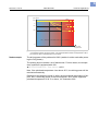
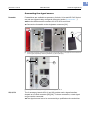
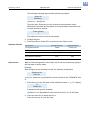
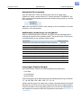
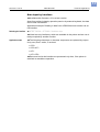
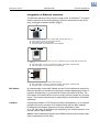
03/10 Rev. 5.04-02
USER MANUAL
AP 4.4 – AP 5.4 – AP 5.6 – AP 7.t – 64-xx – DPM – PEM – ALX 92x – PM 3000
Advanced Applications
Printing with temperature compensation ....... 2
Requirements ............................................ 2
Function description .................................. 2
Printing with start signal ................................ 4
Application notes ....................................... 4
Available interfaces ................................... 4
Connecting the signal source .................... 5
Settings in the parameter menu ................ 7
Standalone Operation ................................... 9
Requirements ............................................ 9
Functional Description ............................. 10
Selecting files from memory card ............ 11
Executing printjobs .................................. 13
Executing firmware files .......................... 13
Automatic file execution .......................... 14
Additionally usable keys on a keyboard .. 14
Insert Input Field in Printjob .................... 14
Example Application ................................ 15
Data input by interface ............................ 17
Data Transmission with Ethernet ................ 18
System Requirements ............................. 18
Integration of Ethernet Interface .............. 19
Setting the IP Parameters ....................... 20
Transmission with Raw Socket Interface 20
Transmission with LPD Server ................ 21
Troubleshooting ...................................... 21
Data transmission with FTP ........................23
Requirements ..........................................23
Function description .................................23
Building up a connection ..........................23
Data transmission with WLAN .....................25
Requirements ..........................................25
Notes .......................................................25
Printer setup ............................................26
Connecting ...............................................26
PC setup ..................................................27
Testing the connection .............................28
Sending a printjob ....................................28
Storing and transferring parameter settings 29
Recommendations ...................................29
Application cases .....................................29
Storing settings on memory card .............30
Loading settings from CF card .................31
Automatic setup loading ..........................31
Verifying Bar Codes with OLV .....................32
System Requirements .............................32
Functional Description .............................32
Setup .......................................................33
Appendix .....................................................35
Example: Setup file for AP 5.4 .................35
2
03/10 Rev. 5.04-02
USER MANUAL
Advanced Applications
AP 4.4 – AP 5.4 – AP 5.6 – AP 7.t – 64-xx – DPM – PEM – ALX 92x – PM 3000
Printing with temperature compensation
Requirements
• Suitable printers: All devices listed in the headline of this document
• Firmware: All versions
Function description
The print contrast is heavily dependent on the temperature of the printhead.
This can be set using the parameter SYSTEM PARAMETERS > Print contrast or in
the online mode after pressing the Esc button.
When the printer is being used for a big print job, the temperature of the printhead and the print contrast increase during printing. This increase is greater,
the larger the printjob and the larger the amount of black to be printed.
In extreme cases, this rise in temperature can lead to smearing in fine structures when printed, e.g. barcodes arranged crosswise to the printing direction.
To avoid this, the firmware constantly checks and corrects the printhead temperature. The precondition for this is that the parameter SYSTEM PARAMETERS
> Temp. reduction is set to a value > 0 (Default: 20%).
¯ The temperature compensation is the greater, the higher the setting of the
parameter SYSTEM PARAMETERS > Temp. reduction is [1].
Parameter
Function
Sets the print contrast, i.e. indirectly, the printhead
SYSTEM PARAMETERS >
temperature (actually adjusts the driving power of
Print contrast
the printhead).
Sets the correction factor for the temperature comSYSTEM PARAMETERS > pensation. The higher the selected setting, the
Temp. reduction
greater the reduction of the driving power when the
printhead temperature rises.
[Tab. 1] Parameters for setting the temperature compensation.
3
03/10 Rev. 5.04-02
USER MANUAL
Advanced Applications
AP 4.4 – AP 5.4 – AP 5.6 – AP 7.t – 64-xx – DPM – PEM – ALX 92x – PM 3000
Drive performance
print head
TR=0
100
%
TR=20%
80
TR=40%
60
TR = “SYSTEM PARAMETERS / Temp. reduction”
0
26
[1]
Readout example
54
°C
Print head
temperature
With the parameter SYSTEM PARAMETERS > Temp. reduction activated, the driving power of the printhead
– and therefore indirectly the print contrast – are reduced. Reduction starts at a temperature of 26°C.
The maximum value is maintained at 54°C and above.
The driving power of the printhead is 100% (setable in online mode after pressing the Prog button).
The printing layout contains a lot of black areas. For this reason, the temperature reduction is activated with 40%.
« SYSTEM PARAMETERS > Temp. reduction = 40%.
Now, if the printhead temperature rises above 26°C, the driving power will be
reduced automatically.
Reading out the diagram results in: With a given printhead temperature of approx. 40°C, the driving power is reduced to approx. 80%; with a supposed
printhead temperature of 54°C or above, it is reduced to 60%.
4
03/10 Rev. 5.04-02
USER MANUAL
Advanced Applications
AP 4.4 – AP 5.4 – AP 5.6 – AP 7.t – 64-xx – DPM – PEM – ALX 92x – PM 3000
Printing with start signal
Application notes
Print-and-Apply systems are normally triggered by an external start signal,
which typically comes from a product sensor placed at the conveyor. In most
cases, after a start signal arrived, a label is printed, dispensed and applied on
the product.
This chapter describes…
• different ways of connecting a start signal source
• required settings in the printer parameter menu
Available interfaces
Singlestart a
USI b
AI c
E/A d
Depending on the printer type and configuration, different interfaces for start
signal input are available (Tab. 2).
64-xx Dispenser
S
O
--
--
64-xx
O
O
--
--
AP 5.4 Dispenser
S
--
--
O
AP 4.4
O
--
--
--
AP 5.4
O
--
--
O
AP 5.6
O
--
--
O
AP 7.t
O
--
--
O
ALX 92x
O
O
O
--
Printer
[Tab. 2] Interfaces for start signal input for the different printer types
(S = Standard; O = Optional; -- = No option)
a)
b)
c)
d)
Singlestart connector on the devices rear side
USI board with signal interface
Applicator Interface with signal interface
I/O board with signal interface
5
03/10 Rev. 5.04-02
USER MANUAL
Advanced Applications
AP 4.4 – AP 5.4 – AP 5.6 – AP 7.t – 64-xx – DPM – PEM – ALX 92x – PM 3000
Connecting the signal source
Footswitch
Footswitches are available as accessory for both, 64-xx and AP 5.4/5.6 printers and are shipped ready configured (see topic section Accessories ).
¯ Note the different article numbers for AP 5.4/5.6 and 64-xx!
« Connect the footswitch to the singlestart connector [2A].
A
A
B
B
[2]
C
Single-start connector (A) and I/O board signal connector (B) at AP 5.4 red (left) and at AP 5.4 black or
AP 5.6 (right) respectively. Matching footswitch (C) with 3-point plug.
A
B
[3]
USI, AI, E/A
USI signal connector (A) and singlestart connector (B) at a 64-xx.
The 3 accessory boards USI, AI and I/O provide each a signal interface
shaped as a D-Sub connector [2B] [3A]. To those connectors, a start signal
source can be connected.
¯ The signal source has to be connected by a qualified service technician.
6
03/10 Rev. 5.04-02
USER MANUAL
Advanced Applications
AP 4.4 – AP 5.4 – AP 5.6 – AP 7.t – 64-xx – DPM – PEM – ALX 92x – PM 3000
For detailed information on connecting a signal source see (Tab. 3):
Board
Cross-Reference
USI
Topic section „Electronics Gen. 3“, chapter „USI board“,
Circuit diagrams for signal inputs on page 23
AI
Topic section „Applicator Interface“, chapter „Interface description“, Circuit diagrams for signal inputs on page 19
I/O
Topic section „Service Electronics“, chapter „I/O board“,
Input/Output Signals on page 19
[Tab. 3] Topic sections with information about connecting the signal sources to be found in the service manual of the appropriate printer.
Light barrier
(64-xx Dispenser type M and AP 5.4/5.6 Dispenser only) This printer type is
shipped with a short dispensing edge [4B] with a light barrier, which serves as
signal source. After printing and dispensing, the label blocks the light barrier
and stopps the printer until the label is taken off. As soon as the light barrier is
clear again, the next label is printed.
« Connect the light barrier to the D-Sub connector at the printer front side
[4A].
A
B
[4]
AP 5.4 Dispenser.
7
03/10 Rev. 5.04-02
USER MANUAL
Advanced Applications
AP 4.4 – AP 5.4 – AP 5.6 – AP 7.t – 64-xx – DPM – PEM – ALX 92x – PM 3000
Settings in the parameter menu
Setting
Interface
Printer
Parameter
Value
Accept start
signals
--
All
SYSTEM PARAMETER >
External signal
Singlestart
64-xx Dispenser
SYSTEM PARAMETER >
Start source
„Foot switch“
64-xx
-- a
--
AP 5.4 Dispenser,
AP 5.6 Dispenser
DISPENSER PARA >
Start source
„Foot switch“
AP 5.4, AP 5.6, AP 7.t
--
--
64-xx Dispenser
SYSTEM PARAMETER >
Start source
„Light barrier“
AP 5.4 r/b Dispenser,
AP 5.6 Dispenser
DISPENSER PARA >
Start source
„Light barrier“
64-xx Dispenser
SYSTEM PARAMETER >
Start source
USI
64-xx, ALX 92x
--
--
I/O
AP 5.4, AP 5.6, AP 7.t
--
--
AI
ALX 92x
--
--
64-xx, AP 5.4, AP 7.t
SYSTEM PARAMETER >
Signal edge
„Rising edge“
64-xx, AP 5.4, AP 7.t
SYSTEM PARAMETER >
Start mode
Edge
AP 5.4 Gen II, AP 5.6
SYSTEM PARAMETER >
Start print mode
„Pulse rising“
USI
64-xx, ALX 92x
DP INTERFACE >
Start print mode
„Pulse rising“
I/O
AP 5.4, AP 5.6, AP 7.t
I/O BOARD >
Start print mode
„Pulse rising“
AI
ALX 92x
APPLICATOR PARA >
Start print mode
„Pulse rising“
Singlestart
input
AP 5.4 Gen II Dispenser,
AP 5.6 Dispenser
DISPENSER PARA >
Start offset
USI
64-xx, ALX 92x
DP INTERFACE >
Start delay
AP 5.4, AP 7.t
I/O BOARD > Start delay
AP 5.4 Gen II, AP 5.6
--
ALX 92x
APPLICATOR PARA >
Start delay
Singlestart
input
Signal
source
Disp. edge
light barrier
USI
Singlestart
input
Signal flange
Start delay
I/O
AI
Enter distance
between start
sensor and dispensing edge
[Tab. 4] Overview on the most important settings for start signal application (Firmware versions 3.33/5.33/7.34 Pre 4081).
a)
„--“ = No setting required.
¯ Further settings for 64-xx Dispenser see user manual 64-xx, topic section
„Setup“, chapter Settings for dispensing printers on page 17.
8
03/10 Rev. 5.04-02
USER MANUAL
Advanced Applications
AP 4.4 – AP 5.4 – AP 5.6 – AP 7.t – 64-xx – DPM – PEM – ALX 92x – PM 3000
¯ Settings for application of ALX 92x with applicator see service manual
ALX 92x, topic section „Applicator Interface“, chapter
Selecting an applicator type on page 4.
9
03/10 Rev. 5.04-02
USER MANUAL
Advanced Applications
AP 4.4 – AP 5.4 – AP 5.6 – AP 7.t – 64-xx – DPM – PEM – ALX 92x – PM 3000
Standalone Operation
Requirements
Printer
Firmware
Suitable printers: all devices listed in the headline of this document, except for
AP 4.4 (which has no card slot)
Printer
64-xx, DPM, PEM, ALX 92x
64-xx, DPM, PEM, ALX 92x
Feature
Gen. 2
Gen.
Firmware version
a
3.0
3b
5.02
PM 3000
--
5.03n
AP 5.4, AP 7.t
--
1.10
MLK
3.34
AP 5.4 Gen II, AP 5.6
[Tab. 5] Minimum firmware requirement for standalone operation.
a)
b)
CPU board
Characteristic feature: No USB interfaces, but Centronics as standard.
Characteristic feature: USB interfaces, Centronics optional.
Printer
Feature
CPU board number
64-xx, DPM, PEM, ALX 92x
Gen. 2
A2292 / A2293
64-xx, DPM, PEM, ALX 92x
Gen. 3
A6621
PM 3000
--
A6621
AP 5.4, AP 7.t
--
A3927
MLK
A100150
AP 5.4 Gen II, AP 5.6
[Tab. 6] Minimum CPU board requirement for standalone operation.
Options board
Is required for the printer types listed below to be able to connect a keyboard.
The order number for the options board can be found in topic section Accessories .
• 64-xx Gen. 2
• DPM Gen. 2
• PEM Gen. 2
• ALX 92x Gen. 2
Memory card
For order number, see the Plugin Card Manual, topic Available Cards .
Card reader
PC or laptop with card reader
10
03/10 Rev. 5.04-02
USER MANUAL
Advanced Applications
AP 4.4 – AP 5.4 – AP 5.6 – AP 7.t – 64-xx – DPM – PEM – ALX 92x – PM 3000
Keyboard
On request, a keyboard can be connected to the printer. This considerably
simplifies entry of variable data, especially when dealing with text.
¯ 64-xx, DPM, PEM and ALX 92x of Generation 2 require an additional board
for connecting the keyboard, see chapter Options board on page 9. The Options board provides a PS/2 connector; an USB-to-PS/2 adapter comes with
the offered keyboards.
Keyboard type
USB-keyboard a
Order #
without numeric keypad, German layout
USB-keyboard a) without numeric keypad, US layout
Numeric keypad, German layout
b
A4056
A4054
A4219
[Tab. 7] Keyboards available as accessory.
a)
b)
Comes with USB-to-PS/2 adapter (required for „AP 5.4 red“ and for „64-xx Gen. 2“)
With PS/2 connector, therefore only suitable for „AP 5.4 red“ and for „64-xx Gen. 2“.
The matching keyboard layout is set with parameter SYSTEM PARAMETER >
keyboard.
¯ Before first use, check if the intended keyboard really works with the
printer.
Functional Description
Standalone operation means the printer can be operated without it needing to
be connected to a host computer. For this purpose, a PC is used to store the
print job on a CompactFlash card (CF card). After this card is plugged into the
card slot at the printer, the operator can start the print jobs on demand. For
this, he uses the printer control panel or a keyboard connected to the printer.
Variable data can also be entered via the control panel or the external keyboard.
The standalone mode can always be accessed from the „normal“ printer operation (with online/offline mode and message mode). To do so, press the
Online and Esc buttons simultaneously.
It is helpfull to imagine two consoles, between which can be switched by pressing Online+Esc.
Console
„Normal operation“
Console
„Standalone operation“
Online mode
Selecting print jobs
Offline mode
Message mode
Parameter menu
Online
Inserting field contents
+
Inserting print amounts
Esc
Starting print jobs
Error messages are faded in
[Tab. 8] Functions and display texts in normal and in standalone operation mode.
11
03/10 Rev. 5.04-02
USER MANUAL
Advanced Applications
AP 4.4 – AP 5.4 – AP 5.6 – AP 7.t – 64-xx – DPM – PEM – ALX 92x – PM 3000
Features
Standalone operation in brief:
• Printing without computer connection
• Data entry via control panel or keyboard
• Reading print job from the CF card
• Entry or selection of field content
• Updating Firmware from CF card
Selecting files from memory card
Requirements
64-xx/DPM/PEM/ALX 92x/PM 3000 (each Gen. 3) with firmware version 5.31
or above, an optional second card slot is supported. The card slot which is
used for standalone operation must provide the drive letter C.
« Set INTERF.PARAM. > DRIVEASSIGNMENT > Drive C to „Compact flash“ or
„Compact flash 2 “ („Compact flash 2“ appears only with the optional 2nd card
slot).
AP 5.4 schwarz, AP 5.6:
« Set INTERF.PARAM. > DRIVEASSIGNMENT > Drive C to „SD card“ (= factory setting).
Other printers: No settng required
Selectable are files with the following extentions:
• „*.FOR“ (printjob)
• „*.S3B“ (firmware)
¯ The files must be stored on CF card in folder „\FORMATS“.
¯ If no file with one of the above listed endings is found in folder „\FORMATS“, or if no CF card is inserted, the following message appears:
Standalone
No files!
Selecting a file
1. Press the Online + Esc buttons to get into the standalone mode. The following is displayed:
Choose a file
Avery.for
„Avery.for“ stands for any printjob file, which is stored in the „FORMATS“
folder.
Assumption: More than one file is stored in the „FORMATS“ folder: In this
case the first file in alphabetical order is displayed.
2. Press the Cut or Feed button to step to the next file.
¯ Press the Esc button to jump back to the first entry of the list.
3. Press the Online button to start proceeding the file
In case of a printjob file, the printjob is started, in case of a firmware file,
the firmware upload starts.
12
03/10 Rev. 5.04-02
USER MANUAL
Advanced Applications
AP 4.4 – AP 5.4 – AP 5.6 – AP 7.t – 64-xx – DPM – PEM – ALX 92x – PM 3000
The following message appears after selecting a printjob:
Avery.for
Executing .
„Avery.for“ = printjob file
The point after „Executing“ moves as long as the interpreter works.
Afterwards, input data are requested. If no input fields are provided, only
the print amount is queried:
Enter quantity
1
The initial print amount is set in the printjob.
4. Change the print
5. Press the buttons Online+Esc to get back to the Online mode.
Key/button functions
Operation
Printer button
Keyboard key
Feed
Cursor Up
Cut (or Apply)
Cursor Down
Online
Enter
Esc
Esc
Go to previous file
Go to next file
Confirm the selection
More than one file: jump back to
the first file in the list
[Tab. 9] Keys for file selection
Quick selection
¯ If an external keyboard is connected, the file can be selected by typing in
the first letter of the file name.
Example:
After changing to the standalone mode, the following is displayed:
Choose a file
Avery.for
„Avery.for“ stands for any printjob file, which is stored in the „FORMATS“ folder.
1. Press the key for the first letter of the wanted file name , e. g. „D“. Display:
D
Default.for
D stands for the typed-in character.
„Default.for“ is in alphabetical order the first file with a „D“ as first letter.
2. Press the enter key to select the file, or
Press the esc key to undo the input.
13
03/10 Rev. 5.04-02
USER MANUAL
Advanced Applications
AP 4.4 – AP 5.4 – AP 5.6 – AP 7.t – 64-xx – DPM – PEM – ALX 92x – PM 3000
Executing printjobs
All input fields are polled, which are defined as such in the print job (see
Example Application on page 15). Next, the print quantity is requested. As
soon as the print quantity is confirmed (online button), the print job is executed.
From now on, all information about the job is displayed in the "Print control"
console. While the print job is processed, it is started newly in the „Standalone“
console. The input fields are polled again, with the previous entries as default.
Alternating with the first input field, the text „Start next job“ is diplayed.
¯ Each printjob file may contain only one printjob. If any printjob file contains
more than one printjobs, only the first printjob is executed.
¯ The new start of the print job can be avoided by setting the parameter SYSTEM PARAMETERS > Single job mode to „deactivated“.
¯ Press the Esc button to go back to the file selection.
Operation
Increase by 1
Decrease by 1
(the predecessor of 0 is 9)
Enter
Delete/Cancel
Printer button
Keyboard key
Feed
Cursor Up
Cut (or Apply)
Cursor Down
Online
Enter
Esc
Esc
[Tab. 10] Keys for entering variable data
¯ It's also possible to enter a single „* “ for the print quantity. This makes the
print quantity „endless“.
Executing firmware files
Files with the extension ".S3B" are firmware files. Selecting a firmware file
means starting a firmware download. As this is a fundamental intervention to
the system, firmware files are not executed immediately. The query "Firmwaredownload ? No/Yes" demands explicit confirmation of the operator.
¯ The same firmware file remamed to the extension „.FOR“ is executed
without querying.
Operation
Printer button
Keyboard key
Switch between Yes/No
Feed
Cursor Up
Switch between Yes/No
Cut (or Apply)
Cursor Down
Online
Enter
Esc
Esc
Confirm the selection
More than one file: jump back to
the first file in the list
[Tab. 11] Keys for loading firmware files
14
03/10 Rev. 5.04-02
USER MANUAL
Advanced Applications
AP 4.4 – AP 5.4 – AP 5.6 – AP 7.t – 64-xx – DPM – PEM – ALX 92x – PM 3000
Automatic file execution
If the file "DEFAULT.FOR" (All letters lower case or all upper case;
„Default.for“ doesn´t work) exists on CF card in the folder "\FORMATS", this
file is executed automatically at system start. Display during power up, until the
file is executed:
Standalone
Initializing
¯ If a file "\AUTOSTRT.FOR" is also existing (in the root directory, not casesensitive), it is executed first.
Additionally usable keys on a keyboard
With an external keyboard connected, the printer can be operated without
touching the buttons of the operation panel. The function keys F5-F8 can be
used alternatively to the operation panel buttons:
Operation
Keyboard key
Delete the current print job (works in both consoles)
Ctrl+Del
Jump to the start (e.g. start of a file selection list)
Ctrl+Home
Jump to the end (e.g. end of a file selection list)
Ctrl+End
Change between Standalone and standard console
Ctrl+Ins
Delete backwards
Backspace
Same function as printer button
F5
Same function as printer button
F6
Same function as printer button
F7
Same function as printer button
F8
[Tab. 12] Additional keys for operating the printer with an external keyboard.
Insert Input Field in Printjob
Input fields can be defined in the following Easy Plug field types:
• Text field
• Counting field
• Barcode field
These field types can be defined through the following Easy Plug commands:
YT, YN, YB, IDM, PDF, MXC, CBF, YC, YS, YG.
Using a special syntax it is made clear in these commands that the text dealt
with here is not a fixed text, but text requested at the time of implementation.
Further information on the input field syntax can be found in the description of
the respective command in the Easy Plug Manual, topic section Description of
commands .
15
03/10 Rev. 5.04-02
USER MANUAL
Advanced Applications
AP 4.4 – AP 5.4 – AP 5.6 – AP 7.t – 64-xx – DPM – PEM – ALX 92x – PM 3000
Example Application
1. Generate two text files with the content shown in the tables below.
¯ Tip: Cut out the content using the Acrobat Reader text selection tool
and copy it to a text file.
Example
#!A1#IMN100/60#ER
#J40#T5#YT107/0///Simple test for
#J30#T5#YN100/0/60///STANDALONE Mode
#Q3/
[Tab. 13] File „TEST1.FOR“
Example
#J10#T5#YT107/0///Fixtext#G
#J40#T5#YN100/0/60///$<Color:>,Lightred
#J40#T5#YN100/0/60///$<Color:>,Lightred
#J20#T5#YT107/0///$<Article number:>,
#!A1#IMN100/60#ER
#Q3/
[Tab. 14] File „AVERY.FOR“
2. Create a directory on the CF card called “\FORMATS”.
3. Store the two text files as “TEST1.FOR” and “AVERY.FOR” on the CF card
in the directory “\FORMATS”.
¯ The file ending must be “*.FOR”!
¯ There is no difference made between uppercase and lowercase letters!
4. Switch off printer.
5. Insert CF card into the printer’s card slot.
6. Turn on printer and switch to online mode.
7. Simultaneously press the Online and ESC keys.
The first file on the CF card is displayed:
Choose a file
AVERY
.FOR
8. Call up the file “TEST1.FOR” by pressing the Cut or Feed keys.
¯ On DPM or ALX 92x , please press the Apply instead of the Cut key!
9. Confirm selection by pressing the Online button.
Now you are asked for the quantity of labels to be printed:
Enter quantity
3
Quantity 3 appears as default, as this was already preset in the printjob. To
increase the quantity to 10, for instance, please perform the following procedure:
16
03/10 Rev. 5.04-02
USER MANUAL
Advanced Applications
AP 4.4 – AP 5.4 – AP 5.6 – AP 7.t – 64-xx – DPM – PEM – ALX 92x – PM 3000
10. Press the ESC key. This erases the 3.
11. Press the Feed button in order to incrementally increase (up to a max. of
9) the quantity of labels to be printed.
¯ Quantity 0 = infinite printing!
12. Press the Online button to move forward by one position. Should you wish
to enter a number with two or more digits, simply increase the second digit
using the Feed button. Should the number only have one digit, press the
Online button again.
The printer will now print the stipulated number of labels.
AVERY.FOR
In case of the “AVERY.FOR” file, this works somewhat differently. Once the
file is called up, the following is displayed:
ONLINE
1 JOBS
Color: Lightred
In the second line the printer will ask for the content for the first data field.
“Color” is a prompt and therefore not printed. The preset content of the printjob
is called “Lightred”.
• Without keyboard you can enter the desired text in characters. Entering letters works in the same way as digit entry (see example “TEST1.FOR”). Using the Cut or Feed buttons, you can scroll through the available set of
characters until the required character appears. Use the Online button to
move forward by one position. After entering the last character, press the
Online button twice.
• With a keyboard you can, after the input prompt “Color:”, simply enter a different content.
¯ The entry may only have a length that ensures the printout does not extend
over the label edge! - otherwise a printer error message is displayed!
The next input field is displayed and then the next etc., until all input fields have
been processed.
At the end you may change the quantity of labels to be printed if required.
17
03/10 Rev. 5.04-02
USER MANUAL
Advanced Applications
AP 4.4 – AP 5.4 – AP 5.6 – AP 7.t – 64-xx – DPM – PEM – ALX 92x – PM 3000
Data input by interface
¯ Available with firmware x.33 or a later version.
Apart from putting in data by operation panel or by external keyboard, the data
can be sent via interface.
Application example: Reading in data from a RS232 barcode scanner via serial interface.
Selecting the interface
« INTERF.PARAM. > OPTIONS > StandAlone Input
¯ Listed are only interfaces, which are available in the printer and are not already occupied by another function.
Application notes
¯ The following characters or character sequences are replaced by respectively one „Enter“ action, if received.
• <CR>
• <CR><LF>
• <LF>
• <LF><CR>
¯ Data received at the interface are processed only then, if the printer is
switched to standalone operation.
18
03/10 Rev. 5.04-02
USER MANUAL
Advanced Applications
AP 4.4 – AP 5.4 – AP 5.6 – AP 7.t – 64-xx – DPM – PEM – ALX 92x – PM 3000
Data Transmission with Ethernet
System Requirements
CAUTION! - Unqualified manipulations of a data network can disturb or stop
its proper functioning.
Connecting a device to a network requires network administrator knowledge.
« Consult your network administrator for assistance, if you don´t have knowledge on this level!
Hardware
• Printer
Printer
Feature
AP 4.4
–
AP 5.4
–
AP 5.6
–
AP 7.t
–
Ethernet connection by
Ethernet connection not possible!
Integrated Ethernet interface
64-xx
DPM
PEM
Gen. 2
CPU board A2292 with integrated Ethernet interface (optional)
Gen. 3
Integrated Ethernet interface
–
Integrated Ethernet interface
ALX 92x
64-xx
DPM
PEM
ALX 92x
PM 3000
[Tab. 15] Equippement of the different printer types witih Ethernet interfaces.
• Ethernet cable: must have quality „Cat. 5E“ and be shielded.
Software
• Firmware:
Printer
Feature
Firmware version
64-xx, DPM, PEM, ALX 92x
Gen. 2
3.0
64-xx, DPM, PEM, ALX 92x
Gen. 3
5.02
PM 3000
--
5.03n
AP 5.4, AP 5.6, AP 7.t
--
alle Versionen
[Tab. 16] Minimum firmware requirement if it is to apply the Ethernet function.
• Network protocol: TCP/IP
19
03/10 Rev. 5.04-02
USER MANUAL
Advanced Applications
AP 4.4 – AP 5.4 – AP 5.6 – AP 7.t – 64-xx – DPM – PEM – ALX 92x – PM 3000
Integration of Ethernet Interface
The Ethernet interface of the printers is layed out as 10/100 Base T. The transmission speed is set by autonegotiation. LEDs are located above the RJ 45
plug, showing the network situation [5][6][7].
B
A
[5]
Position of the signal LEDs at 64-xx, DPM, PEM, ALX 92x (each Gen. 2).
A LED red lights = Printer is connected to network
B LELD yellow flashes = Network traffic
C LED green lights = High transmission rate (100 Mbit/s)
A
[6]
C
B
Position of the signal LEDs at AP 5.4 red, AP 7.t, PM3000 and 64-xx, DPM, PEM, ALX 92x (each
Gen. 3)
A LED yellow lights = Printer is connected to network; LED flashes =Network traffic
B LED green lights = High transmission rate (100 Mbit/s)
B
A
[7]
Position of the signal LEDs at AP 5.4 black and AP 5.6.
A LED yellow lights = Printer is connected to network; LED flashes =Network traffic
B LED green lights = High transmission rate (100 Mbit/s)
MAC Address
An internationally unique MAC (Media Access Control) address is required for
Ethernet operation. It consists of 6 bytes and is usually separated by colons or
hyphens (hexadecimal, e.g. 00:0a:44:02:00:49 or 00-0a-44-02-00-49). The
first 3 bytes are constant 00:0A:44 (Avery code), the last 3 bytes vary for each
device. The product manufacturer is responsible for the allocation of the MAC
addresses.
IP Address
In the printer software a TCP/IP protocol stack is implemented, i.e. for network
purposes the device requires an IP address along with the MAC address.
IP-addresses are always displayed as 4 bytes separated by dots
(e.g. 192.168.1.99). IP addresses are assigned by the network operator, as a
rule the network administrator.
¯ MAC and IP addresses originate from different protocol layers and are generally independent of each other.
20
03/10 Rev. 5.04-02
USER MANUAL
Advanced Applications
AP 4.4 – AP 5.4 – AP 5.6 – AP 7.t – 64-xx – DPM – PEM – ALX 92x – PM 3000
Further information about TCP/IP can be found in the abundance of literature
on the subject.
Setting the IP Parameters
The IP-parameter settings can either be set fix, or they can be requested from
a DHCP server with every start of the printer. To assist the system administrator, the DHCP server is provided a device name on request, which consists of
a combination of printer type + 3 digits from the MAC address. (e.g.
AP_5.4___300dpi_020049). The following values have been preset:
• IP address: 192.168.1.99
• Net mask: 255.255.255.0
• Default gateway: 0.0.0.0
¯ Connection to a name server is not required.
Menu
Parameter
Description
IP addressassign
Here, please set “fixed IP address” or
“DHCP”.
INTERF. PARAM. > IP address
NETWORK PARAM
Net mask
Gateway address
IP parameter input fields, in case “fixed
IP address” was set for the address assign type.
[Tab. 17] Setting the IP parameters in the printer menu
¯ WARNING: The address allocation for each device must be clear and unambiguous. Ask your network administrator for assistance!
Transmission with Raw Socket Interface
Printing data can be transmitted using a parameterisable socket interface
(TCP server socket on port number > 1024).
This protocol is supported by
• all Unix derivatives; a connection similar to that of terminal servers can be
established.
• Windows 2000, Windows XP
A software package from external providers is required for Windows 95,
Windows 98 and Windows NT (e.g. Serial/IP by Tactical Software,
http://www.tacticalsoftware.com).
In this way you can set the Port address in the printer’s parameter menu:
Parameter
Description
Here you can select the port numINTERF. PARAM. > NETWORK PARAM. >
ber of the service in section 1024Port address
65535
Here a TCP/IP socket must be set
INTERF. PARAM. > EASYPLUGINTERPR >
in order to receive printing data at
Interface
the set port number.
[Tab. 18] Setting the port address in the printer´s parameter menu
21
03/10 Rev. 5.04-02
USER MANUAL
Advanced Applications
AP 4.4 – AP 5.4 – AP 5.6 – AP 7.t – 64-xx – DPM – PEM – ALX 92x – PM 3000
Transmission with LPD Server
Printing data can be transmitted to the printer using the LPR/LPD (Line Printer
Daemon) protocol (“BSD Spooler”).
This protocol is supported by
• all Unix derivatives
• Windows NT, Windows 2000 und Windows XP
¯ The print queue of the host must be named „lp“!
Example
1. Set parameter INTERF.PARAM. > EASYPLUGINTERPR > Interface to „LPD server“.
2. Send the printjob file (here: „test.txt“) as illustrated using the „lpr“ command
[8].
[8]
Sending a printjob with the „lpr“ command.
¯ Enter „lpr ?“ to get a list of the admissible command options.
¯ For the use of LPD server under Windows NT or Windows 2000, please
refer to the following link:
http://support.microsoft.com/default.aspx?scid=kb;EN-US;179156
¯ For the use of LPD server under Windows 95 and Windows 98, a software package from external providers is required (e.g. Windows LPR
Spooler, see the following link).
http://home.arcor.de/Heil-Consulting/
Troubleshooting
The following should be checked if a problem occurs:
• Ethernet connection: The yellow LED belonging to the printer network
socket must be illuminated. If this is not the case, possible sources of error
are:
– that the network is not connected to the outlet.
– ISDN outlet: Erroneous, the network cable was connected to an ISDN
instead of a network outlet. Both outlet types do not differ mechanically.
– an incorrect cable (ISDN cable?) is used to connect the printer to the
network outlet.
– a defective hub/switch.
– a defective printer board.
• IP parameter: The defined parameters or parameters set via DHCP are
displayed in the “Printer Status” printout. A “ping” to the set IP address
must return an echo. This also works if a different interface is set in the
Easy Plug Interpreter parameter. Possible source of error: Incorrect configuration of a network participant.
22
03/10 Rev. 5.04-02
USER MANUAL
Advanced Applications
AP 4.4 – AP 5.4 – AP 5.6 – AP 7.t – 64-xx – DPM – PEM – ALX 92x – PM 3000
• On the printer, either “TCP/IP socket” or “LPD server” must be set in the
Easy Plug Interpreter parameter.
23
03/10 Rev. 5.04-02
USER MANUAL
Advanced Applications
AP 4.4 – AP 5.4 – AP 5.6 – AP 7.t – 64-xx – DPM – PEM – ALX 92x – PM 3000
Data transmission with FTP
Requirements
• Suitable printers: All printers listed in the headline, apart from the AP 4.4
(which has no card slot)
• Network connection (see )
• Firmware:
Printer
Feature
Firmware version
64-xx, DPM, PEM, ALX 92x
Gen. 2
3.40
64-xx, DPM, PEM, ALX 92x
Gen. 3
5.02
PM 3000
--
5.03n
AP 5.4, AP 7.t
--
3.0
MLK
3.34
AP 5.4 Gen II, AP 5.6
[Tab. 19] Minimum firmware requirement if it is to apply the FTP client.
• FTP-client is installed on the host computer. The following FTP-clients are
released for communication with the internal FTP-server:
– Microsoft-Internet Explorer (IE) 5.0, 5.5, 6.0 (OS: Windows NT,
Windows 95)
– WS-FTP Pro 5.0 (OS: Windows NT, Windows 95)
– GNU Midnight Commander 4.6.0 (OS: Linux)
Function description
FTP = File Transfer Protocol
By means of the FTP-client on the host computer, files can be transferred between host computer and printer. The transmission can take place in both directions. The files are stored in the printer on the internal RAM-disk or on a CF
card plugged into the printers card slot.
Building up a connection
Activating the
FTP server
« Set INTERF.PARAM. > NETWORK PARAM. > FTP server to „enabled“.
Before a connection can be built up, the IP-address of the printer must be
known. This is either provided automatically by a DHCP-server or set manually
at the printer (parameter INTERF.PARAM. > NETWORK PARAM. > IP Addressassign
and INTERF.PARAM. > NETWORK PARAM. > IP Address).
For details refer to Setting the IP Parameters on page 20.
24
03/10 Rev. 5.04-02
USER MANUAL
Advanced Applications
AP 4.4 – AP 5.4 – AP 5.6 – AP 7.t – 64-xx – DPM – PEM – ALX 92x – PM 3000
Login
Example using IE: Type „ftp://“ into the URL input field, followed by the IP-address, with guiding zeros left away. Given an IP-address of 144.093.028.194,
the input would be ftp://144.93.28.194 [9]
[9]
Example: Input of the printer´s IP-address into the URL field of the IE.
Then, a dialogue box queries user name and password.
• User name: Any you like, if there is at least one character typed in.
• Password: Is set in the printer parameter INTERF.PARAM. > NETWORK PARAM.
> FTP password. Default setting is „avery“.
If the login was successful, the folders which are contained on CF card and
RAM-disk appear in the FTP client (Tab. 7).
Directory structure
Comments
CF
Only visible, if a CF card is plugged in
FONTS
Font directory on CF card
FORMATS
Printjob directory on CF card
GRAPHICS
Graphics directory on CF card
LOGOS
Logo directory on CF card
FONTS
Font directory on the internal RAM-disk
GRAPHICS
Graphics directory on the internal RAM-disk
LOGOS
Logo directory on the internal RAM-disk
[Tab. 20] Directory structure, which is visible in the FTP client, if a CF card is plugged in.
25
03/10 Rev. 5.04-02
USER MANUAL
Advanced Applications
AP 4.4 – AP 5.4 – AP 5.6 – AP 7.t – 64-xx – DPM – PEM – ALX 92x – PM 3000
Data transmission with WLAN
Requirements
Suitable printers
• AP 5.4, AP 7.t: firmware version 3.00 or higher
• 64-xx, DPM, PEM, ALX 92x, PM 3000: firmware version 5.31 or higher
Revision number
CPU board
• AP 5.4, AP 7.t: at least 3 (A3927-03)
• 64-xx, DPM, PEM, ALX 92x, PM 3000: at least 4 (A6621-04)
« Displaying the revision number: SERVICE DATA > CPU BOARD DATA >
CPU identifier
WLAN CF cards
• D-Link „DCF-660W“ (article number A7456)
• Linksys „WCF12“ (no longer availabe)
• Pretec „OC-WLBXX-A“ (no longer availabe) [10A]
A
B
[10] WLAN CF card (A) ; Wireless Access Point (B)
Further requirements
• Access point according to standard IEEE 802.11b station mode „infrastructure“ (e. g. „Netgear Wireless Access Point WG602“ [10B])
• Ethernet crossed link cable (1:1 cable), to connect the access point to the
host computer
• PC with operating system Windows XP
Notes
WLAN = Wireless Local Area Network
This section describes a simple setup, with which data transmission from a
host computer (e. g. PC) via an access point to a label printer can be testet.
This setup doesn´t suit for real network operation.
26
03/10 Rev. 5.04-02
USER MANUAL
Advanced Applications
AP 4.4 – AP 5.4 – AP 5.6 – AP 7.t – 64-xx – DPM – PEM – ALX 92x – PM 3000
Printer setup
CAUTION! - Network manipulations can disturb or avoid proper network
operation.
« Before connecting any device to a network, always ensure the approval of
the network administrator.
1. Insert the WLAN CF card into the printers card slot. Switch the printer on.
In the printer menu INTERF. PARAM. > NETWORK PARAM., additional parameters for WLAN operation show up.
The LED at the card is flashing as long as the card is not logged in at the
access point.
2. Make the following settings in the INTERF. PARAM. > NETWORK PARAM. menu:
Parameter
Setting
Note
IP addressassign
Fixed IP address
IP address
e. g.
192.168.000.999
ask the network administrator
for it; the initial three bytes must
equal the PC address
Net mask
255.255.255.000
= default setting
WLAN SSID
idt
use lower case letters
WLAN WEP
disabled
WLAN default key
0
or any other setting
FTP server
arbitrary setting
WEB Server
arbitrary setting
[Tab. 21] Required parameter settings in the printer menu.
3. Set parameter INTERF. PARAM. > EASYPLUGINTERPR > Interface to
„LPD Server“.
4. Restart printer to activate the settings.
Connecting
1. Connect the access point to the PC using a crossed link cable. Connect
the access point to the mains supply and switch it on.
2. Check, if the LED at the WLAN CF card lights up permanent. If it does not,
check the following points:
– Is the card plugged firmly into the card slot?
– Does the card match one of the supported card types?
– Is the parameter INTERF. PARAM. > NETWORK PARAM. > WLAN SSID set to
„idt“ (small letters!)?
27
03/10 Rev. 5.04-02
USER MANUAL
Advanced Applications
AP 4.4 – AP 5.4 – AP 5.6 – AP 7.t – 64-xx – DPM – PEM – ALX 92x – PM 3000
PC setup
1. In Windows XP call: Start > Settings > System > Network.
2. Click on Configuration, click the right mouse button and select Properties.
Window [11] shows up.
A
B
[11] „Properties of LAN connection“ window.
3. Select the item „Internet protocol (TCP/IP)“ [11A] and click on the „Properties“ button [11B].
Window [12] appears.
A
B
[12] „Properties of internet protocol (TCP/IP)“ window.
4. Activate the input field for fixed IP addresses [12A].
5. Ask the network administrator for suitable IP addresses. Type the
IP address into field [12B] (e. g. 192.168.0.1).
6. Restart the PC to activate the settings.
28
03/10 Rev. 5.04-02
USER MANUAL
Advanced Applications
AP 4.4 – AP 5.4 – AP 5.6 – AP 7.t – 64-xx – DPM – PEM – ALX 92x – PM 3000
Testing the connection
1. Call the input window: Start > Programs > Accessories > Input prompt.
2. Enter the command „ping“ with the printers IP address, e.g.
„ping 192.168.0.99“.
3. If the connection works properly, four answer lines appear in the input
prompt window [13].
[13] Input prompt window after proceeding ping with the printers IP address.
¯ As an additional test, „ping“ can also be called with the IP address of the
access point. The default IP address of the Netgear WG602 is 192.168.0.227
If the printer doesn´t send back an answer, the connection doesn´t work
properly. Measures in this case are:
« Check all the above mentioned settings.
« Contact the network administrator for advice.
Sending a printjob
1. Have an Easy-Plug printjob ready (in this example: „test.txt“).
2. Send the printjob using the command „lpr“ [14].
[14] Sending a printjob using the lpr command
After some seconds, the printer should start printing.
¯ During data transmission, the LED at the WLAN CF card flashes.
29
03/10 Rev. 5.04-02
USER MANUAL
Advanced Applications
AP 4.4 – AP 5.4 – AP 5.6 – AP 7.t – 64-xx – DPM – PEM – ALX 92x – PM 3000
Storing and transferring parameter settings
Recommendations
• Suitable printers: All printers listed in the headline, apart from the AP 4.4
(which has no card slot)
• Firmware:
Printer
Feature
Firmware version
64-xx, DPM, PEM, ALX 92x
Gen. 2
3.40
64-xx, DPM, PEM, ALX 92x
Gen. 3
5.02
PM 3000
--
5.03n
AP 5.4, AP 7.t
--
3.00
MLK
7.34
AP 5.4 Gen II, AP 5.6
[Tab. 22] Minimum firmware requirement if it is to store or transfer parameter settings.
Application cases
Sometimes, it will be necessary to reinstall all parameter settings of a printer
at a time or to transfer the settings to another printer. In those cases, the operator can save time, money and nerves by loading all the parameter settings
completely. The following cases are possible:
• After a printer is being serviced, it is supposed to get the same settings as
before.
• The parameter settings of one printer are supposed to be transferred to another printer of the same type.
• Several printers of the same type should be provided with the same settings.
It is adviseable to read out and to store the parameter settings completely, to
be able to restore them later. To do so, there are two ways:
Easy-Plug
Reading out via the interface by means of appropriate Easy-Plug commands.
This requires sound knowledge of the command language Easy-Plug and is
not further discussed here.
Further information: refer to the Easy-Plug manual, topic section Description
of commands , commands #!PG and #PC.
CF card
Storing the parameter settings on CF card in a text file („setup file“) (see description below).
30
03/10 Rev. 5.04-02
USER MANUAL
Advanced Applications
AP 4.4 – AP 5.4 – AP 5.6 – AP 7.t – 64-xx – DPM – PEM – ALX 92x – PM 3000
Storing settings on memory card
1. Call parameter SPECIAL FUNCTION > Parameter to CF.
¯ AP 5.4 black, AP 5.6: Call SPECIAL FUNCTION > Store parameters.
¯ This parameter is only visible, if a memory card is plugged into the printer card slot.
2. Select a storing option: „With adjust para“ or „Without adj. par“.
– „With adjust para“
(Default setting) Parameters, which carry device specific settings, are
also saved. Examples for this type of settings are the printhead resistance and the sensor settings.
The relevant parameter names are marked with a „* “ in the setup file.
This option is recommended, if the settings are supposed to be reinstalled on the same printer.
– „Without adj. par“
Parameters, which carry device specific settings, are not saved.
This option is recommended, if settings are supposed to be transferred
to another printer of the same type.
3. After having chosen the storing option, the default file name is displayed
(storing location: directory \FORMATS on CF card):
– SETUPALL.FOR for SPECIAL FUNCTION > Parameter to CF = „With adjust
para“
– SETUP.FOR for SPECIAL FUNCTION > Parameter to CF = „Without adj. par“
¯ File names and directory can be modified with the printer operation buttons
or with a connected keyboard.
¯ If a file with the given name already exists, it will be overwritten without further inquiry.
Command ID
Parameter name
Setting
#G Printer System Menu
#PC2001/24.50
#G Head disp dist.
: 24.5 mm
#PC2002/0
#G Speed unit
: Inch/s
#PC2003/36.40
#G Foil end warning
: 36.4 mm
#PC2004/0
#G Display mode
: Job rest quant.
#PC2005/0
#G *Dispense counter
:0
#PC2006/0
#G w/wo magazine
: with
#PC2007/0
#G Autom. dot check
: Off
#PC2008/10
#G Earliest dottest
: after 10 label
#PC2009/0
#G Latest dotcheck
: after 0 label
#PC2010/0
#G Dottestarea from
: 0 mm
#PC2011/104
#G Dottestarea to
: 104 mm
#PC2012/0
#G Print emulation
: Easyplug
#PC2013/9
#G Character Sets
: IBM
[Tab. 23] Example: Detail of a setup file.
31
03/10 Rev. 5.04-02
USER MANUAL
Advanced Applications
AP 4.4 – AP 5.4 – AP 5.6 – AP 7.t – 64-xx – DPM – PEM – ALX 92x – PM 3000
For an example of a complete listing of a setup file, refer to .
Loading settings from CF card
All files with parameter settings, which are stored in the \FORMATS directory,
can be read out using the standalone mode.
¯ The file extension must be „.FOR“, see Selecting files from memory card on page 11.
Automatic setup loading
« Save the setup file as \AUTOSTRT.FOR (in the root directory on CF card).
Loading the settings:
1. Switch the printer off.
2. Insert the CF card.
3. Switch the printer on. The setup loading starts automatically. Display text
when the settings are loaded:
Switch off.
Remove card
32
03/10 Rev. 5.04-02
USER MANUAL
Advanced Applications
AP 4.4 – AP 5.4 – AP 5.6 – AP 7.t – 64-xx – DPM – PEM – ALX 92x – PM 3000
Verifying Bar Codes with OLV
System Requirements
Printer
• Suitable printers: 64-xx / DPM / PEM / ALX 92x.
• Printer firmware: at least version 3.30
¯ With firmware v. 3.30, the OLV can only be connected to Com2, that is,
the option board A2294 must be installed in the printer.
OLV
• SV100 with power supply, interface cable and mounting plate.
Part
Order # (RJS)
Scanner/OLV
002-7973
Installation kit with PC software
and power supply
002-8107
Mounting plate with scanner
bracket
002-4608
[Tab. 24] Ordering numbers of the manufacturer for the SV 100.
• Firmware version: X302
• Manufacturer: RJS www.RJS1.com • Serial data cable (1:1) to connect printer and OLV.
• For use outside of the USA, a country specific power cable is required.
Cable
Order # (Avery)
Serial cable
A1207
Power cable euro norm
90600
Power cable UK
A0635
Power cable switzerland
A0842
Power cable denmark
A3598
[Tab. 25] Accessories for the SV 100 available at Avery
Functional Description
An OLV is a bar code scanner, which is able to rate the scanned bar code in
quality (according to ANSI grades). The OLV is placed in front of the printer,
so that it can read the bar codes directly after printing [15].
¯ Only the OLV „SV100“ by RJS can be used.
¯ Only bar codes can be verified, which are printed with a rotation of 0° or
180°.
33
03/10 Rev. 5.04-02
USER MANUAL
Advanced Applications
AP 4.4 – AP 5.4 – AP 5.6 – AP 7.t – 64-xx – DPM – PEM – ALX 92x – PM 3000
Setup
1. Place the printer on the OLV mounting plate as illustrated.
¯ Operating the OLV at a DPM / PEM / ALX 92x requires a support stand
matching the respective installation situation
2. Connect the OLV to the serial interface of the printer.
¯ After the printer has been switched on, initialization commands are sent
to the OLV. Therefore, the OLV has first to be switched on. These initialization commands switch on the laser beam (among other things).
¯ The sending of the initialization commands can be repeated at any time
by pressing the Feed and Esc buttons (at the printer) simultaneously. This
may be necessary, if the OLV was switched off.
3. Switch on the OLV.
4. Switch on the printer.
5. Set the printer parameter INTERF. PARAM. > OPTIONS > OLV option to
„Serial Com1“ or „Serial Com2“, depending on the port on which the OLV
is connected.
¯ (Firmware 3.30: Set the printer parameter INTERF. PARAM. > COM2 PORT
> Function Option to „Barcode OLV“.)
The data transfer parameters of the interface are automatically set to the
default values required by the SV100 (115 200 baud, 8 data bits, no parity,
2 stop bits, hardware handshake).
6. Position the OLV so, that the distance between laser beam (on the label)
and printhead is as short as possible.
¯ For detailed information on setting the OLV please refer to the SV100
manual.
7. Set the parameters in the OLV PARAMETERS menu (at the printer).
Information about the parameters can be found in topic section Info-Printouts and Parameters .
[15] 64-05 with OLV mounted (front view).
34
03/10 Rev. 5.04-02
USER MANUAL
Advanced Applications
AP 4.4 – AP 5.4 – AP 5.6 – AP 7.t – 64-xx – DPM – PEM – ALX 92x – PM 3000
[16] 64-05 with OLV mounted (side view).
35
03/10 Rev. 5.04-02
USER MANUAL
Advanced Applications
AP 4.4 – AP 5.4 – AP 5.6 – AP 7.t – 64-xx – DPM – PEM – ALX 92x – PM 3000
Appendix
Example: Setup file for AP 5.4
#!A1
#G Machine Setup for AP 5.4
300 Dpi
Version: V3.10
#G Serial number
: A424904304797
#G MAC Address
: 000a.44.02.13.8c
#G Creation date
: 05.05.2006 16:01
#G--------------------------------------------------------------------#G Printer Parameter Menu
#G--------------------------------------------------------------------#PC1001/1
#G Infeed no.
: Nr. 1
#PC1002/8
#G Inf. change spd. : 8 Inch/s
#PC1003/4.0
#G Print speed
: 4 Inch/s
#PC1004/4.0
#G Feed speed
: 4 Inch/s
#PC1005/1
#G Materialtype
: Punched
#PC1006/200.0
#G Materiallength
: 200.0 mm
#PC1007/48.0
#G Materialwidth
: 48.0 mm
#PC1027/0
#G Print direction : Foot first
#PC1008/0.0
#G Punch offset
: 0.0 mm
#PC1009/1
#G Bar code multip. : * 1
#PC1010/0
#G UPC plain-copy
: In line
#PC1011/0
#G EAN Readline
: Standard
#PC1012/0
#G EAN sep. lines
: With readl. only
#PC1013/0
#G Rotated barcodes : Normal
#PC1014/0
#G Cut mode
: Real 1:1 mode
#PC1015/3
#G Cut speed
: 3 Inch/s
#PC1016/105
#G Cut width
: 105 mm
#PC1017/0.0
#G Cut position
: 0.0 mm
#PC1018/0.0
#G Double cut
: 0.0 mm
#PC1019/1
#G Rewind direction : Printing outside
#PC1020/0.0
#G *X - Printadjust : 0.0 mm
#PC1021/0.0
#G *Y - Printadjust : 0.0 mm
#PC1022/0
#G Punchmode
: Automatic
#PC1023/128
#G Punchlevel
: 128
#PC1024/30
#G Matend
: 30
#G--------------------------------------------------------------------#G Easyplug Interpreter
#G--------------------------------------------------------------------#PC1101/2
#G Interface
: TCP/IP SOCKET
#PC1102/0
#G Spooler mode
: Mult. print jobs
#PC1103/1
#G *Printer ID no.
: 1
#PC1104/64
#G Spooler size
: 64 KBytes
#G--------------------------------------------------------------------#G COM1 Port Parameter
#G--------------------------------------------------------------------#PC1201/5
#G Baud rate
: 9600 Baud
#PC1202/8
#G No. of data bits : 8
#PC1203/2
#G Parity
: None
#PC1204/1
#G Stop bits
: 1 Bit
#PC1205/0
#G Data synch.
: RTS/CTS
#PC1206/0
#G Serial port mode : RS232
36
03/10 Rev. 5.04-02
USER MANUAL
Advanced Applications
AP 4.4 – AP 5.4 – AP 5.6 – AP 7.t – 64-xx – DPM – PEM – ALX 92x – PM 3000
#PC1207/1
#G
Frame error
: Display
37
03/10 Rev. 5.04-02
USER MANUAL
Advanced Applications
AP 4.4 – AP 5.4 – AP 5.6 – AP 7.t – 64-xx – DPM – PEM – ALX 92x – PM 3000
#G--------------------------------------------------------------------#G COM2 Port Parameter
#G--------------------------------------------------------------------#PC1302/5
#G Baud rate
: 9600 Baud
#PC1303/8
#G No. of data bits : 8
#PC1304/2
#G Parity
: None
#PC1305/1
#G Stop bits
: 1 Bit
#PC1306/0
#G Data synch.
: RTS/CTS
#PC1307/0
#G Serial port mode : RS232
#PC1308/1
#G Frame error
: Display
#G--------------------------------------------------------------------#G COM3 Port Parameter
#G--------------------------------------------------------------------#PC1351/2
#G Baud rate
: 9600 Baud
#PC1354/1
#G Parity
: None
#PC1356/0
#G Data synch.
: RTS/CTS
#PC1358/1
#G Frame error
: Display
#G--------------------------------------------------------------------#G COM4 Port Parameter
#G--------------------------------------------------------------------#PC1361/2
#G Baud rate
: 9600 Baud
#PC1364/1
#G Parity
: None
#PC1366/0
#G Data synch.
: RTS/CTS
#PC1368/1
#G Frame error
: Display
#G--------------------------------------------------------------------#G Centronics Port Parameter
#G--------------------------------------------------------------------#PC1401/1
#G PnP function
: On
#G--------------------------------------------------------------------#G Ethernet Parameter
#G--------------------------------------------------------------------#PC1501/0
#G IP Addressassign : DHCP
#PC1502/-1872945967 #G *IP address
: 144.093.028.209
#PC1503/-65536
#G *Net mask
: 255.255.000.000
#PC1504/0
#G *Gateway address : 000.000.000.000
#PC1505/9100
#G Port address
: 9100
#PC1506/0
#G Ethernet speed
: Auto negotiation
#PC1521/1
#G SNMP Agent
: Enabled
#PC1522/public#G
#G SNMP password
: public
#PC1507/1
#G FTP server
: Enabled
#PC1508/avery#G
#G FTP Password
: avery
#PC1509/1
#G WEB server
: Enabled
#PC1510/5
#G WEB display refr : 5 s
#PC1511/admin#G
#G WEB admin passw. : admin
#PC1512/supervisor#G
#G WEB supervisor p.: supervisor
#PC1513/AP5.4_300dpi_02138C#G#G DHCP host name
:
AP5.4_300dpi_02138C
#PC1514/idt#G
#G WLAN SSID
: idt
#PC1515/0
#G WLAN WEP
: Disabled
#PC1516/1
#G WLAN default key : 1
#PC1517/123456789aBCd123456789AbcD#G#G WLAN key 1
:
123456789aBCd123456789AbcD
38
03/10 Rev. 5.04-02
USER MANUAL
Advanced Applications
AP 4.4 – AP 5.4 – AP 5.6 – AP 7.t – 64-xx – DPM – PEM – ALX 92x – PM 3000
#PC1518/123456789aBCd123456789AbcD#G#G
123456789aBCd123456789AbcD
#PC1519/123456789aBCd123456789AbcD#G#G
123456789aBCd123456789AbcD
#PC1520/123456789aBCd123456789AbcD#G#G
123456789aBCd123456789AbcD
WLAN key 2
:
WLAN key 3
:
WLAN key 4
:
39
03/10 Rev. 5.04-02
USER MANUAL
Advanced Applications
AP 4.4 – AP 5.4 – AP 5.6 – AP 7.t – 64-xx – DPM – PEM – ALX 92x – PM 3000
#G--------------------------------------------------------------------#G Options Parameter
#G--------------------------------------------------------------------#PC5300/0
#G Remote Display
: Disabled
#G--------------------------------------------------------------------#G Printer System Menu
#G--------------------------------------------------------------------#PC2001/24.5
#G Head disp dist. : 24.5 mm
#PC2002/0
#G Speed unit
: Inch/s
#PC2003/36.4
#G Foil end warning : 36.4 mm
#PC2060/0
#G Foil warn stop
: Disabled
#PC2004/0
#G Display mode
: Job rest quant.
#PC2005/372
#G *Dispense counter : 372
#PC2006/0
#G w/wo magazine
: with
#PC2012/0
#G Print emulation : Easyplug
#PC2013/3
#G Character sets
: Germany
#PC2014/0
#G Character filter : Chars >= 20Hex
#PC2015/0
#G Light sens. type : Punched
#PC2016/0
#G Head-sensor dist :
0 mm
#PC2017/50
#G Sens. punch-LS
: 50 %
#PC2018/0
#G Foil mode
: Thermo transfer
#PC2019/9.9
#G Ribb. eco. limit : 9.9 mm
#PC2058/0
#G Feed mode
: Head up
#PC2020/1
#G Turn-on mode
: Online
#PC2021/0
#G Interface delay :
0 ms
#PC2022/1
#G Error reprint
: Enabled
#PC2023/0
#G Single-job mode : Disabled
#PC2025/1106
#G *Head resistance : 1106 Ohm / 12 Dot
#PC2026/20
#G Temp. reduction : 20 %
#PC2066/1
#G Thin line emphas : On
#PC2027/0
#G Voltage offset
:
0 %
#PC2028/1
#G Logo expansion
: Yes
#PC2029/0
#G Miss. label tol. : 0
#PC2031/1
#G Periph. device
: Cutter
#PC2032/2
#G Infeed module
: 2 infeeds
#PC2033/1
#G Singlestartquant : 1
#PC2035/0
#G Application mode : Save mode
#PC2036/0
#G Appl. waitpos.
:
0 mm
#PC2037/10
#G Applicator speed : 10 Inch/s
#PC2038/0
#G Start mode
: Edge
#PC2039/0
#G Start source
: Light barrier
#PC2057/0
#G Calibration mode : Automatic
#PC2042/0
#G External signal : Disabled
#PC2043/0
#G Signal edge
: Falling edge
#PC2044/1
#G Apply key
: Enabled
#PC2045/99
#G Print contrast
: 99 %
#PC2046/512
#G Ram disk size
: 512 KBytes
#PC2047/256
#G Font downl. area : 256 KBytes
#PC2048/1024
#G Free store size : 1024 KBytes
#PC2049/2
#G Print info mode : Compact right
#PC2050/0
#G Reprint function : Disabled
#PC2051/1
#G Language
: English
#PC2063/1
#G Keyboard
: English
#PC2053/0
#G Access authoriz. : Deactivated
#PC2059/80
#G Max InitFeedback :
80 mm
#PC1026/0
#G Material feed
: for- / backwards
40
03/10 Rev. 5.04-02
USER MANUAL
Advanced Applications
AP 4.4 – AP 5.4 – AP 5.6 – AP 7.t – 64-xx – DPM – PEM – ALX 92x – PM 3000
#G--------------------------------------------------------------------#G Peripheral Parameter Menu
#G--------------------------------------------------------------------#PC2512/1
#G Rewinder Motor
: Generation 2
#PC2501/0
#G Current mode
: Table values
#PC2502/100
#G Min rew. current : 100
#PC2503/250
#G Max rew. current : 250
#PC2504/170
#G Min rew. current : 170 %
#PC2505/170
#G Max rew. current : 170 %
#PC2506/0
#G Start rew. curr. :
0 %
#PC2507/30
#G Start cur. len. :
30 mm
#PC2508/95
#G Pullback current : 95
#PC2509/50
#G Back diameter
:
50 mm
#PC2510/0
#G Break current
: 0
#PC2511/120
#G Break diameter
: 120 mm
#G--------------------------------------------------------------------#G Dispenser Interface
#G--------------------------------------------------------------------#PC3001/0
#G Interface type
: USI interface
#PC3002/0.0
#G Start delay
: 0.0 mm
#PC3003/0
#G Start print mode : Pulse falling
#PC3004/0
#G End print mode
: Mode 0
#PC3005/0
#G Reprint signal
: Disabled
#PC3006/1
#G Ribbon signal
: Enabled
#PC3007/0
#G Material signal : Disabled
#PC3013/60.0
#G Diam. mat. end
: 60.0 mm
#PC3008/0
#G Feed input
: Standard
#PC3012/0
#G Pause input
: Standard
#PC3009/0
#G Start error stop : Off
#PC3010/1
#G Internal inputs : Enabled
#PC3011/0
#G Apply mode
: After start sig.
#G--------------------------------------------------------------------#G Textile Parameter Menu
#G--------------------------------------------------------------------#PC3301/1
#G Changelabel Mode : Always at jobend
#PC3302/1
#G Changelab Print : With print
#PC3303/10
#G Changelab Length : + 10 mm
#PC3304/1
#G Label Eject Mode : Yes, at job end
#PC3305/0
#G Head lift autom. : after 0 labels
#G--------------------------------------------------------------------#G Applicator Parameter Menu
#G--------------------------------------------------------------------#PC3101/0
#G Applicator type : LTP - LTPV
#PC3102/0
#G Apply mode
: After start sig.
#PC3110/2
#G Start print mode : Pulse rising
#PC3103/0
#G Start error stop : Off
#PC3104/0
#G APSF sensor res. :
0 pulses/m
#PC3105/0.0
#G Start delay
: 0.0 mm
#PC3106/1
#G Dwell time
:
1 ms
#PC3107/1
#G Blow on time
:
1 ms
#PC3108/0
#G Restart delay
:
0 ms
#PC3109/2000
#G Position timeout : 2000 ms
#PC3212/0
#G Start error stop : Off
41
03/10 Rev. 5.04-02
USER MANUAL
Advanced Applications
AP 4.4 – AP 5.4 – AP 5.6 – AP 7.t – 64-xx – DPM – PEM – ALX 92x – PM 3000
#G--------------------------------------------------------------------#G I/O Board Parameter Menu
#G--------------------------------------------------------------------#PC3201/0.0
#G Start delay
: 0.0 mm
#PC3202/0
#G APSF sensor res. :
0 pulses/m
#PC3203/0
#G Start print mode : Pulse falling
#PC3204/0
#G Reprint signal
: Disabled
#PC3205/0
#G Feed input
: Disabled
#PC3206/0
#G Pause input
: Disabled
#PC3207/0
#G Error output
: Printer error
#PC3208/0
#G Error polarity
: Level low active
#PC3209/1
#G Status output
: Low ribbon warn.
#PC3210/0
#G Status polarity : Level low active
#PC3211/0
#G End print mode
: Mode0 inactive
#G--------------------------------------------------------------------#G MLI Parameter Menu
#G--------------------------------------------------------------------#PC4002/15
#G Darkness
: 15
#PC4003/126
#G Control Prefix
: 7EH
#PC4004/94
#G Format Prefix
: 5EH
#PC4005/44
#G Delimiter Char
: 2CH
#PC4006/0
#G Label Top
: 0 Dots
#PC4007/0
#G Left Position
: 0 Dots
#PC4009/0
#G Resolution
: 300 DPI
#PC4010/0
#G Error Indication : OFF
#PC4011/0
#G Error Checking
: YES
#PC4012/0
#G 305 DPI Scaling : YES
#PC4013/0
#G Image Save Path : Internal RAM
#PC4014/1
#G Command ^PR
: Enable
#PC4015/1
#G Command ^MT
: Enable
#PC4017/0
#G Label Invert
: Disable
#PC4016/1
#G Command ^JM
: Enable
#G--------------------------------------------------------------------#G Printer Special Menue
#G--------------------------------------------------------------------#PC5001/1
#G *Printer type
: AP 5
#PC5002/1
#G *Printhead type
: KPA 300 DPI
#PC5004/0
#G Command sequence : ‚#G‘
#PC5005/0
#G EasyPl. file log : Disabled
#G--------------------------------------------------------------------#G Printer Service Menu
#G--------------------------------------------------------------------#PC5111/0
#G Spec parameter 1 : 0
#PC5112/0
#G Spec parameter 2 : 0
#PC5113/0
#G EasyPlug Monitor : Disabled
#PC5125/0
#G EP Monitor Mode : Interpreter data
#PC5116/127
#G *Punch adjust
: 127
#PC5117/128
#G *Reflex adjust
: 128
#PC5119/234
#G *Foil adjust
: 234
#PC5120/170
#G *Head sens adjust : 170
#PC5121/0
#G *Optn.1
: 0
#PC5122/0
#G *Optn.2 adjust
: 0
#PC5101/35
#G Matend tolerance :
35 mm
#PC5102/0.0
#G Feed adjust
: 0.0 %
42
03/10 Rev. 5.04-02
USER MANUAL
Advanced Applications
AP 4.4 – AP 5.4 – AP 5.6 – AP 7.t – 64-xx – DPM – PEM – ALX 92x – PM 3000
#PC5103/0.0
#G Foil feed adjust : 0.0 %
#PC5104/0.0
#G *Punch y calibr. : 0.0 mm
#PC5123/31775
#G *Rewinder adjust : 31775
#PC5127/1
#G Debug interface : Serial Com1
#PC5124/0
#G Debug mask
: 0
#PC5128/-1872945986 #G Debug IP address : 144.093.028.190
#G--------------------------------------------------------------------#G Module Firmware Versions
#G--------------------------------------------------------------------#G readonly
ID=30004#G System version
: V3.10
#G readonly
ID=30052#G Peripheraldriver : V 3 - T 3
#G readonly
ID=30057#G Intern. rewinder : V 4 - T 36
43
03/10 Rev. 5.04-02
USER MANUAL
Advanced Applications
AP 4.4 – AP 5.4 – AP 5.6 – AP 7.t – 64-xx – DPM – PEM – ALX 92x – PM 3000
#G--------------------------------------------------------------------#G Operational Data
#G--------------------------------------------------------------------#G readonly
ID=30014#G Serv. operations : 0
#G readonly
ID=30015#G Head number
: 0
#G readonly
ID=30016#G Roll number
: 0
#G readonly
ID=30017#G Cutter number
: 0
#G readonly
ID=30018#G Head run length : 441 m
#G readonly
ID=30019#G Roll run length : 401 m
#G readonly
ID=30020#G Cuts on knife
: 881
#G readonly
ID=30021#G Tot. mat. length : 401 m
#G readonly
ID=30022#G Tot. foil length : 358 m
#G readonly
ID=30023#G Total cuts
: 881
#G readonly
ID=30025#G Head strobes
: 3978688
#G readonly
ID=30026#G Foil diameter
: 67.8 mm
#G readonly
ID=30028#G Operation time
: 209 hours 46 min
#G--------------------------------------------------------------------#G Power supply data
#G--------------------------------------------------------------------#G readonly
ID=30029#G Type
: Blue Mountain
#G--------------------------------------------------------------------#G CPU board data
#G--------------------------------------------------------------------#G readonly
ID=30034#G CPU identifier
: 25-0
#G readonly
ID=30036#G PCB Revision
: REV03
#G readonly
ID=30037#G FPGA version
: 5817
#G readonly
ID=30039#G MAC Address
: 000a.44.02.13.8c
#G readonly
ID=30040#G Serial number
: A424904304797
#G readonly
ID=30041#G Production date : 03.08.2004
#G readonly
ID=30042#G PCB part number : A3407-03
#G readonly
ID=30043#G Board part numb. : A4249-01
#G readonly
ID=30044#G Manufacturer
: Multitech Sys
#G readonly
ID=30045#G Work place
: FCT Test Station
#G readonly
ID=30046#G Company name
: Avery Dennison
#G--------------------------------------------------------------------#G CF card slot status
#G--------------------------------------------------------------------#G readonly
ID=30047#G Card in slot
: Yes
#G readonly
ID=30048#G Card typ
: 3.3 Volt
#G--------------------------------------------------------------------#G Internal Memory Configuration
#G--------------------------------------------------------------------#G readonly
ID=30010#G Space for Jobs
: 7.8 MB
#G readonly
ID=30007#G Ram memory size : 16 MB
#G readonly
ID=30008#G Flash mem size
: 4 MB
FUJ
#G readonly
ID=30009#G Compact flash
: 32 MB
#G readonly
ID=30010#G Space for Jobs
: 7.8 MB
#G readonly
ID=30011#G Max. Labellength : 1984 mm
#G readonly
ID=30013#G Default values
: User defined
#G--------------------------------------------------------------------#G Printer Debug Menu
44
03/10 Rev. 5.04-02
USER MANUAL
Advanced Applications
AP 4.4 – AP 5.4 – AP 5.6 – AP 7.t – 64-xx – DPM – PEM – ALX 92x – PM 3000
#G--------------------------------------------------------------------#PC5403/0
#G Pctrl communica. : Disabled
#PC5402/0
#G Variables
: Disabled
#PC5400/0
#G Label generation : Disabled
#PC5401/0
#G Print handling
: Disabled
#G--------------------------------------------------------------------#G Execute system restart ( 217 parameters )
#G--------------------------------------------------------------------#PC999999/-1#G
45
03/10 Rev. 5.04-02
USER MANUAL
Advanced Applications
AP 4.4 – AP 5.4 – AP 5.6 – AP 7.t – 64-xx – DPM – PEM – ALX 92x – PM 3000
Index
Numerics
10/100 Base T 19
A
Access Point 25
ANSI grades 32
Apply button 15
C
CF card 10
Cut Button 15
E
Easy Plug field types 14
Example, offline function application 15
F
FTP 23
I
IP address 19
ISDN outlet 21
L
LED 19
LPD server 21
M
MAC address 19
N
Network administrator 18
O
OLV 32
P
Parameter settings, storing and loading 29
Printer contrast 2
Printhead driving power 3
R
Raw Socket Interface 20
S
Standalone mode 10
SV100 32
T
TCP/IP 19
W
WLAN 25