1
VARI❋LITE® Control Systems
Virtuoso™ / Virtuoso™ DX
Console User’s Manual
SV 4.2
Express yourself.
VARI❋LITE® - VIRTUOSO™ / VIRTUOSO™ DX CONSOLE USER’S MANUAL
VARI❋LITE®, Artisan®, mini-Artisan®, mini-Artisan®2, Artisan®Plus, mini-Artisan®Plus, VL2®, and VLD® are
trademarks owned by Vari-Lite, Inc., 201 Regal Row, Dallas TX 75247 USA. and are registered in the United States and other
countries.
VL1000™, VL2000™, VL2201™, VL2202™, VL2400™ (and the individual product designations), VL3000™, Virtuoso™,
Virtuoso™ DX, VARI❋LITE Visionary™, VL1™, VL2B™, VL2C™, VL3™, VL4™, VL5™, VL5Arc™, VL5B™, VL6™,
VL6B™, VL6C™, VL7™, VL7B™, VLM™, APS6™, C3™, ArtisanVLQ™, SPC-36™, UDM™, AutoTruss™, SmartDMX™,
Smart Repeater™, Series 100™, Series 200™, Series 300™, Series 2000™, Series 3000™, DICHRO❋WHEEL™,
DICHRO❋TUNE™, VACU❋DEP™, VARI❋IMAGE™, VARI❋BEAM™, and the Vari-Lite Asterisk are also trademarks
owned by Vari-Lite, Inc.
VARI❋LITE® products are protected by one or more of the following patents, and other pending patent applications worldwide:
U. S. Patents No. 6,123,436; 6,113,252; 6,046,861; 6,031,749; 6,011,640; 5,969,868; 5,959,768; 5,934,794; 5,882,107; 5,829,868;
5,825,548; 5,798,619; 5,774,273; 5,769,527; 5,758,956; 5,728,994; 5,640,061; 5,590,954; 5,454,477; 5,432,691; 5,367,444;
5,329,431; 5,307,295; 5,282,121; 5,278,742; 5,209,560; 5,186,536; 5,073,847; 5,010,459; 4,980,806; 4,972,306; 4,800,474;
4,779,176; 4,701,833; 4,602,321;
U. S. Design Patents No. 439,356; 420,332; 417,300; 415,301; 413,995; 377,338; 366,712; 359,574; 350,408; 347,113;
Australia Patents No. 693,691; 683,695; 667,109; 649,264; 646,588; 586,095; 576,400; 546,433;
Australia Design Patents No. 128,796; 128,795;
Canada Patents No. 2,070,670; 2,050,375; 1,270,675; 1,259,058; 1,181,795;
Canada Design Patents No. 81,234; 81,233; 76,046;
European (UK) Patents No. 0 652 400; 0 586 049; 0 565 218; 0 547 732; 0 534 710; 0 495 305; 0 474 202; 0 379 970; 0 253 082;
0 253 081; 0 248 974; 0 192 882; 0 140 994; 0 060 068;
Germany Patents No. 694 25 943.8; 693 14 122.0; 692 08 615.3; 692 07 692.1; 691 31 478.0; 691 21 029.2; 690 33 385.4; 37 89
166.9; 37 68 727.1; 37 51 804.6; 37 50 201.8; 35 87 270.5; 32 79 888.1; 32 74 291.6;
Germany Design Patents No. M 98 01 745.4; M 96 04 515.9; M 96 04 514.0; M 94 07 689.8; M 94 02 951.2; M 499 03 583.6; M
498 11 203.9; G 93 12 884.3;
Spain Patents No. 2 090 191; 2 084 289; 2 020 960; 0 548 328;
Spain Utility Model Patent No. 2.031.748;
Spain Design Patents No. 0.137.502; 0.137.501; 0.133.573;
Greece Patent No. 910.400.544;
Hong Kong Patents No. 965/1990; 285/1987;
Japan Patents No. 2,843,696; 2,059,669; 2,055,324; 2,002,168; 1,966,525; 1,889,481; 1,792,721; 1,770,241; 1,723,825;
1,683,007; 1,533,011;
Japan Design Patents No. 985,985-1; 985,985; 947,552; 945,436-1; 945,436; 1,106,089; 1,077,598; 1,072,598; 1,060,414;
1,002,123;
Korea Patents No. 76,310; 42,639; 283,770; 181,180;
Korea Design Patents No. 209,896; 209,895;
Mexico Patent No. 180,148;
Singapore Patents No. 663/90; 134/87;
Taiwan Patents No. 78,726; 66,975; 65,380; 28,275;
United Kingdom Design Registrations No. 2082526; 2072562; 2056387; 2056386; 2042174; 2038212; 2033108; 2029499.
Apple®, Macintosh®, and FireWire® are registered trademarks of Apple Computer, Inc.
Zip® is a registered trademark of Iomega® Corporation.
All other brand or product names which may be mentioned in this manual are trademarks or registered trademarks of their
respective companies or organizations.
Virtuoso™ / Virtuoso™ DX Console User’s Manual
The information furnished in this manual is for informational use only and is subject to change without notice. Vari-Lite, Inc.
assumes no responsibility or liability for any errors or inaccuracies that may appear in this manual. All information and graphic
representations are property of Vari-Lite, Inc. 201 Regal Row, Dallas, Texas 75247 USA.
Version as of: 23-Sep-02
Printed in the USA.
Part number: 02.9651.0001 C
Virtuoso™ / Virtuoso™ DX Console User’s Manual
© 2001-2002 Vari-Lite, Inc. All Rights Reserved.
ii
23-Sep-02
02. 9651.0 001 C
VARI❋LITE® - VIRTUOSO™ / VIRTUOSO™ DX CONSOLE USER’S MANUAL
End User Software License
PLEASE READ THIS DOCUMENT CAREFULLY BEFORE ACTIVATING, COPYING, INSTALLING,
OR USING THIS SOFTWARE PROVIDED BY VARI-LITE, INC. BY ACTIVATING, COPYING,
INSTALLING, OR USING THIS SOFTWARE, YOU ARE AGREEING TO BE BOUND BY THE TERMS
OF THIS LICENSE. IF YOU DO NOT AGREE TO THE TERMS OF THIS LICENSE, DO NOT ACTIVATE, COPY, INSTALL, OR USE THIS SOFTWARE AND PROMPTLY RETURN IT FOR A REFUND.
1. License. Vari-Lite, Inc. (“Vari-Lite”) hereby grants you a limited license to install and use the
Virtuoso™ DX software and related documentation (collectively, the “Software”) solely with the Virtuoso DX
console sold in conjunction with the Software. Vari-Lite retains all right, title and interest to the Software which
is protected by various proprietary rights, including but not limited to copyrights, trade secrets, or patents
("Proprietary Rights"). No license, right or interest in any trademark, trade name or service mark of Vari-Lite or
any third party is granted under this License.
2. No Implied License. You acknowledge that this License in no way shall be construed to provide an
implied license to use, modify or improve any of Vari-Lite’s patented technology, copyrights, trade secrets,
trademarks, and/or other Proprietary Rights.
3. Restrictions. The Software contains proprietary information that is possibly protected by a
combination of patent, copyright, trade secret, and/or other Proprietary Rights, and constitutes valuable property of
Vari-Lite. You acknowledge that the Software is disclosed in circumstances of confidence and only for use by you
under the terms and conditions of this License and that you do not acquire any rights of ownership or title in the
Software. You may not attempt to create or derive source codes by disassembly, reverse engineering or any other
method, or otherwise reduce the Software to a human-perceivable form. You may not modify or translate any part
of the Software. You may not use, disclose, distribute, make or have made any copies of the Software, in whole or
in part, without the prior written authorization of Vari-Lite. You agree to make reasonable efforts to notify and
inform your employees or agents having access to the Software of your limitations, duties and obligations regarding
non-disclosure and copying of the Software. The Software shall be used only by you, your employees or your
authorized agents. You agree to provide notice to Vari-Lite immediately after learning of or having reason to
suspect a breach of any of the restrictions set forth in this License.
4. Termination. This License is effective until terminated. You may terminate this License at any time
by destroying the Software, and all copies thereof. This License will terminate immediately without notice from
Vari-Lite if you fail to comply with any provision of this License. Upon termination, you must destroy the
Software and all copies thereof.
5. Export Control Requirements. This License, and any technical information supplied during the term of
this License, is made subject to any restrictions concerning the export of products or technical data from the United
States of America which may be imposed upon Vari-Lite or you from time to time by the Government of the United
States of America. Furthermore, you agree that at no time, either during the term of this License or thereafter, will
you knowingly export, directly or indirectly, any United States source technical data acquired from Vari-Lite under
this License or any direct products of that technical data to any country for which the U.S. Government or any
agency thereof at the time of export requires an export license or other governmental approval, without first
obtaining that license or approval when required by applicable United States law.
6. Limited Warranty. Vari-Lite warrants the media on which the Software is recorded to be free from
defects in materials and workmanship under normal use for a period of ninety (90) days from the date of purchase
as evidenced by a copy of your receipt. Vari-Lite’s entire liability and your exclusive remedy will be replacement
of a media that does not meet Vari-Lite’s limited warranty and is returned at your expense, along with a copy of
your receipt, to Vari-Lite customer support or to Vari-Lite’s authorized representative. If replacement of the media
is not reasonably practical or commercially reasonable as determined solely in the discretion of Vari-Lite, Vari-Lite
will refund the purchase price as evidenced by a purchase receipt. Vari-Lite will have no responsibility to replace
media damaged by accident, abuse or misapplication. EXCEPT FOR THE FOREGOING, THE SOFTWARE
AND RELATED DOCUMENTATION ARE PROVIDED "AS IS," WITHOUT ADDITIONAL
WARRANTY OF ANY KIND, AND VARI-LITE EXPRESSLY DISCLAIMS ALL OTHER
WARRANTIES, EXPRESS OR IMPLIED, INCLUDING, BUT NOT LIMITED TO, THE IMPLIED
WARRANTIES OF DESIGN, MERCHANTABILITY, FITNESS FOR A PARTICULAR PURPOSE, OR
TITLE, ANY WARRANTIES ARISING FROM A COURSE OF DEALING, USAGE, OR TRADE
PRACTICE, OR ANY WARRANTIES OF NON-INFRINGEMENT OF ANY THIRD PARTY'S
PATENT(S), TRADE SECRET(S), COPYRIGHT(S) OR OTHER INTELLECTUAL PROPERTY
RIGHTS. VARI-LITE DOES NOT WARRANT THAT THE FUNCTIONS CONTAINED IN THE
SOFTWARE WILL MEET YOUR REQUIREMENTS, OR THAT THE OPERATION OF THE
SOFTWARE WILL BE UNINTERRUPTED OR ERROR-FREE, OR THAT DEFECTS IN THE
SOFTWARE WILL BE CORRECTED. FURTHERMORE, VARI-LITE DOES NOT WARRANT OR
MAKE ANY REPRESENTATIONS REGARDING THE USE OR THE RESULTS OF THE USE OF THE
SOFTWARE OR RELATED DOCUMENTATION IN TERMS OF THEIR CORRECTNESS,
ACCURACY, RELIABILITY, OR OTHERWISE. NO ORAL OR WRITTEN INFORMATION OR
02.9 651.00 01 C
23-Sep-02
iii
VARI❋LITE® - VIRTUOSO™ / VIRTUOSO™ DX CONSOLE USER’S MANUAL
ADVICE GIVEN BY VARI-LITE OR ITS AUTHORIZED REPRESENTATIVE SHALL CREATE ANY
WARRANTY OR IN ANY WAY INCREASE THE SCOPE OF THIS WARRANTY. SHOULD THE
SOFTWARE PROVE DEFECTIVE, YOU (AND NOT VARI-LITE OR ITS AUTHORIZED
REPRESENTATIVE) ASSUME THE ENTIRE COST OF ALL NECESSARY SERVICING, REPAIR OR
CORRECTION. SOME STATES DO NOT ALLOW EXCLUSION OF IMPLIED WARRANTIES, SO
THE ABOVE EXCLUSION MAY NOT APPLY TO YOU. THIS WARRANTY GIVES YOU SPECIFIC
LEGAL RIGHTS, AND YOU MAY ALSO HAVE OTHER RIGHTS WHICH VARY FROM STATE TO
STATE.
7. Limitation Of Liability. UNDER NO CIRCUMSTANCES, INCLUDING NEGLIGENCE,
SHALL VARI-LITE BE LIABLE FOR ANY LOST REVENUE OR PROFITS OR ANY INCIDENTAL,
INDIRECT, SPECIAL, OR CONSEQUENTIAL DAMAGES THAT RESULT FROM THE USE OR
INABILITY TO USE THE SOFTWARE OR RELATED DOCUMENTATION, EVEN IF VARI-LITE OR
ITS AUTHORIZED REPRESENTATIVE HAS BEEN ADVISED OF THE POSSIBILITY OF SUCH
DAMAGES. SOME STATES DO NOT ALLOW THE LIMITATION OR EXCLUSION OF LIABILITY
FOR INCIDENTAL OR CONSEQUENTIAL DAMAGES SO THE ABOVE LIMITATION OR
EXCLUSION MAY NOT APPLY TO YOU. IN NO EVENT SHALL VARI-LITE’S TOTAL LIABILITY
TO YOU FOR ALL DAMAGES, LOSSES, AND CAUSES OF ACTION, WHETHER IN CONTRACT,
TORT (INCLUDING NEGLIGENCE) OR OTHERWISE, EXCEED THE AMOUNT PAID BY YOU FOR
THE SOFTWARE.
8. Arbitration, Jurisdiction, and Venue. You agree that any action at law or in equity arising out of the
License or relating to this Software shall be resolved, individually, through biding arbitration using the then current
rules of the American Arbitration Association, in Dallas, Texas and the resulting decisions may be entered in any
court with proper jurisdiction. This means that if you have a grievance with us, you cannot take us to court, and you
may not join your action with any other party. You can address such grievances through arbitration only and you
are hereby consenting to do it in Dallas, Texas, using Texas' laws (without regard to Texas' conflicts of laws). You
agree that are properly subject to the jurisdiction of the courts of the State of Texas and waive any rights to
challenge personal jurisdiction.
9. Government Licensee. If you are acquiring the Software on behalf of any unit or agency of the United
States Government, the following provisions apply: (a) the Government acknowledges Vari-Lite’s representation
that the Software and its documentation were developed at private expense and no part of them is in the public
domain; (b) the Government acknowledges Vari-Lite’s representation that the Software is "Restricted Computer
Software" as that term is defined in Clause 52.227-19 of the Federal Acquisition Regulations ("FAR") and is
"Commercial Computer Software" as that term is defined in Subpart 227.471 of the Department of Defense Federal
Acquisition Regulation Supplement ("DFARS"). The Government agrees that: (i) if the Software is supplied to the
Department of Defense ("DoD"), the Software is classified as "Commercial Computer Software" and the
Government is acquiring only "limited rights" in the Software and its documentation as that term is defined in
Clause 252.227-7013(a)(13) of the DFARS, and (ii) if the Software is supplied to any unit or agency of the United
States Government other than DoD, the Government’s rights in the Software and its documentation will be as
defined in Clause 52.227-19(c)(2) of the FAR.
10. Indemnity. You agree to indemnify and hold harmless Vari-Lite, and its parents, subsidiaries,
affiliates, officers, directors, shareholders, employees and agents, from and against any costs, losses, liabilities and
expenses, including reasonable attorney’s fees, that Vari-Lite may suffer, incur, or be subjected to by reason of any
claim by a third party due to or arising out of your conduct, your use of the Software, any alleged breach of this
License or the representations and warranties herein, the alleged violation of the rights of any third party, or any
alleged infringement of the intellectual property rights of any third party, including but not limited to your use of
any content, trademarks, service marks, trade names or other intellectual property used in connection with the
Software. Vari-Lite reserves the right to control the exclusive defense of any matter otherwise subject to your
indemnification, which will not excuse your indemnity obligations.
11. Complete Agreement. This License constitutes the entire agreement between the parties with respect
to the use of the Software and supersedes all prior or contemporaneous understandings or agreements, written or
oral, regarding such subject matter.
12. Miscellaneous. If any provision of this License shall be unlawful, void, or for any reason
unenforceable, then that provision shall be deemed severable (or reformable, if necessary), and shall not affect the
validity and enforceability of any remaining provisions. Alternatively, such provision may also be modified to the
extent necessary for its validity.
13.Transfer. This License may be transferred to another party provided the other party reads and agrees to accept
the terms and conditions of this License and you notify Vari-Lite of the transfer in writing.
iv
23-Sep-02
02. 9651.0 001 C
VARI❋LITE® - VIRTUOSO™ / VIRTUOSO™ DX CONSOLE USER’S MANUAL
How To Obtain Warranty Service
A copy of the Vari-Lite, Inc. Limited Warranty was included in the shipping package for this
VARI❋LITE® product.
To obtain warranty service, please contact customer service at 1-877-VARI-LITE
(1-877-827-4548) or [email protected] and request a Return Material Authorization
(RMA) for warranty service. You need to provide the model and serial number of the item
being returned, a description of the problem or failure and the name of the registered user or
organization. If available, you should have your sales invoice to establish the date of sale as
the beginning of the warranty period.
Once you obtain the RMA, pack the product in its original packing material along with a copy
of your invoice (if available) and write the RMA number legibly on or near the shipping
address label. Return the unit, freight prepaid to:
Vari-Lite, Inc.
201 Regal Row
Dallas, TX 75247
Attention: Warranty Service
As stated in the warranty, it is required that the shipment be insured and FOB our service
center.
02.9 651.00 01 C
23-Sep-02
v
VARI❋LITE® - VIRTUOSO™ / VIRTUOSO™ DX CONSOLE USER’S MANUAL
Compliance Notice
FCC
This equipment has been tested and found to comply with the limits for a Class A
digital device pursuant to Part 15 of FCC Rules. These limits are designed to provide
reasonable protection against harmful interference when this equipment is operated in
a commercial environment. This equipment generates, uses, and can radiate radio
frequency energy and, if not installed and used in accordance with Vari-Lite system,
service, and safety guidelines, may cause harmful interference to radio
communications. Operation of this equipment in a residential area is likely to cause
harmful interference, in which case the user will be required to correct the interference
at his/her own expense.
Declaration of Conformity
We declare, under our sole responsibility, that this product complies with the relevant
clauses of the following standards and harmonized documents:
Safety
EN 60950: 1999 Safety Standard for Information Technology Equipment
EMC
EN55022A: 1998 Radiated and Conducted Emissions
EN50082-1: 1997 Generic Immunity Standard
We certify that VARI❋LITE products conform to the protection requirements of
European council directives: 73/23/EEC (LVD) and 89/336/EEC (EMC)
vi
23-Sep-02
02. 9651.0 001 C
VARI❋LITE® - VIRTUOSO™ / VIRTUOSO™ DX CONSOLE USER’S MANUAL
Safety Notice
It is extremely important to read ALL safety information and instructions provided in
this manual and any accompanying documentation before installing and operating the
products described herein. Heed all cautions and warnings during installation and use
of this product.
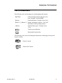
Safety symbols used throughout this manual are as follows:
CAUTION advising of potential damage to product.
WARNING advising of potential injury or death to persons.
GENERAL INFORMATION PERTAINING TO PROTECTION AGAINST FIRE
AND ELECTRICAL SHOCK.
WARNING:
INSTRUCTIONS FOR CONTINUED PROTECTION AGAINST FIRE
1. Replace fuses with same type and rating only.
WARNING:
INSTRUCTIONS FOR CONTINUED PROTECTION AGAINST ELECTRICAL
SHOCK
1. VARI❋LITE® control consoles are designed for dry locations only. Exposure to
rain or moisture may damage the console.
2. Disconnect power before servicing any VARI❋LITE® equipment.
3. Servicing to be performed by qualified personnel only.
WARNING:
RF INTERFERENCE
1. This is a Class A product. In a domestic environment this product may cause radio
interference, in which case, the user may be required to take adequate measures.
02.9 651.00 01 C
23-Sep-02
vii
VARI❋LITE® - VIRTUOSO™ / VIRTUOSO™ DX CONSOLE USER’S MANUAL
Sicherheitshinweise
Es ist äußerst wichtig, ALLE Sicherheitsinformationen und -hinweise in diesem
Handbuch und dem beiliegenden Informationsmaterial zu lesen, bevor Sie die hierin
beschriebenen Produkte installieren bzw. bedienen. Halten Sie bei der Installation und
dem Einsatz dieses Produkts alle Warnhinweise und Vorsichtsmaßnahmen ein.
Folgende Sicherheitssymbole werden in diesem Handbuch verwendet:
VORSICHT - weist auf möglichen Produktschaden hin.
WARNUNG - weist auf mögliche Körperverletzung und Lebensbedrohung hin.
NACHSTEHEND FINDEN SIE ALLGEMEINE HINWEISE ÜBER
SICHERHEITSVORKEHRUNGEN GEGEN FEUER UND ELEKTROSCHOCK.
WARNUNG:
HINWEISE ZUM FEUERSCHUTZ
1. Ersetzen Sie Sicherungen nur mit Sicherungen vom gleichen Typ und gleicher
Stärke.
WARNUNG:
HINWEISE ZUM SCHUTZ GEGEN ELEKTROSCHOCK
1. VARI❋LITE®-Konsole eignen sich ausschließlich für trockene Standorte. Regen
oder Feuchtigkeit können die Konsole beschädigen.
2. Unterbrechen Sie die Stromzufuhr, bevor Sie mit der Arbeit an VARI❋LITE®Geräten beginnen.
3. Die Geräte sollten nur von qualifiziertem Personal gewartet werden.
WARNUNG:
HF-INTERFERENZ
1. Es handelt sich um ein Produkt der Klasse A. In einer Wohnumgebung kann das
Produkt Hochfrequenzstörungen verursachen. In diesem Fall müssen eventuell
geeignete Maßnahmen getroffen werden.
vii i
23-Sep-02
02. 9651.0 001 C
VARI❋LITE® - VIRTUOSO™ / VIRTUOSO™ DX CONSOLE USER’S MANUAL
Notes de sécurité
Avant de procéder à l’installation des produits décrits dans ce guide et de les mettre en
marche, il est extrêmement important de lire TOUS les renseignements et TOUTES
les directives de sécurité contenues dans ce guide ainsi que toute documentation jointe.
Tenir compte de tous les avertissements et suivre toutes les précautions pendant
l’installation et l’utilisation de cet appareil.
Les symboles de sécurité utilisés dans ce guide sont les suivants :
ATTENTION Ce symbole annonce que l’appareil risque d’être
endommagé.
AVERTISSEMENT Ce symbole annonce qu’il y a risque d’accident grave ou même fatal.
CETTE SECTION CONTIENT DES INFORMATIONS GÉNÉRALES POUR SE
PROTÉGER CONTRE LES INCENDIES ET LES DÉCHARGES ÉLECTRIQUES :
AVERTISSEMENT:
DIRECTIVES POUR SE PROTÉGER CONTRE LES INCENDIES
1. Ne remplacer les fusibles qu’avec ceux du même type, ayant les mêmes
caractéristiques.
AVERTISSEMENT:
DIRECTIVES POUR SE PROTÉGER CONTRE LES DÉCHARGES ÉLECTRIQUES
1. Les consoles de commande VARI❋LITE® sont conçues pour une utilisation au
sec uniquement. Une exposition à la pluie et à l’humidité risque d’endommager la
console.
2. Débrancher l’appareil avant de procéder à la révision de tout matériel
VARI❋LITE®.
3. Les révisions doivent être effectuées uniquement par des personnes qualifiées.
AVERTISSEMENT:
INTERFÉRENCE RF
1. Cet appareil est de Classe A. Dans un environnement domestique, cet appareil
peut causer des interférences radio, et si c’est le cas, l’utilisateur peut avoir à
prendre des mesures adéquates.
02.9 651.00 01 C
23-Sep-02
ix
VARI❋LITE® - VIRTUOSO™ / VIRTUOSO™ DX CONSOLE USER’S MANUAL
Aviso sobre Seguridad
Es muy importante leer TODA la información e instrucciones sobre seguridad que se
indica en este manual así como en los documentos adjuntos antes de instalar y operar
los productos descritos. Se debe prestar atención a todos los avisos y advertencias
durante la instalación y uso de este producto.
Los símbolos de seguridad usados en este manual son los siguientes:
CUIDADO, indica posibles daños al producto.
ADVERTENCIA, indica posibles lesiones o muerte a las personas.
LA INFORMACIÓN GENERAL RELACIONADA A LA PROTECCIÓN CONTRA
INCENDIO Y GOLPES DE CORRIENTE ELÉCTRICA:
ADVERTENCIA:
INSTRUCCIONES PARA PROTECCIÓN CONTINUA CONTRA INCENDIO
1. Reemplaze los fusibles solamente con los del mismo tipo y especificación.
ADVERTENCIA:
INSTRUCCIONES PARA PROTECCIÓN CONTINUA CONTRA CHOQUE
ELÉCTRICO
1. Los controles de la consola de VARI❋LITE® están diseñados solamente para
lugares secos. La exposición a la lluvia o humedad pueden dañar la consola.
2. Desconecte la energía antes de dar servicio a cualquier equipo de VARI❋LITE®.
3. El servicio debe ser realizado solamente por personal calificado.
ADVERTENCIA:
INTERFERENCIA RF
1. Este es un producto de Clase A. En el ambiente de la casa este producto puede
ocasionar radiointerferencia, en cuyo caso, el usuario debe tomar las medidas
adecuadas.
x
23-Sep-02
02. 9651.0 001 C
安全性に関する注意事項
ここに記載されている製品を取り扱う場合は、まず本マニュアルおよび付属
のマニュアルの安全性に関する情報と説明をすべてお読みください。また、
実際に本製品を取り付けたり使用する際には、すべての注意事項および警告
に留意して作業してください。
本マニュアルでは、以下の安全マークを使用しています。
注意 : 製品に損傷を与える危険性があります。
警告 : 人身事故につながる危険性があります。
火災防止および感電防止についての一般的な注意事項
警告 :
火災の発生を防ぐためのヒント
1. ヒューズを交換する場合は、同じヒューズ(同じ種類、同じクラス)を使用して
ください。
警告 :
感電を防ぐためのヒント
1. VARI❋LITE® 制御装置は、乾燥した環境で使用するように設計されています。
雨で濡れる場所や湿気の多い場所に取り付けると、制御装置が傷むことがありま
す。
2. VARI❋LITE® 照明器具を修理点検する場合は、必ず先に電源を切ってください。
3. 照明器具の修理点検は、資格を持つ技師のみが行うようにしてください。
警告 :
RF 干渉
1. 本製品は Class A に分類されます。本製品は、家庭環境において無線干渉を起こ
す可能性があります。その場合、使用者は適切な処置を取らなければならないこ
とがあります。
02.9651.0001 C
23-Sep-02
xi
VARI❋LITE® - VIRTUOSO™ / VIRTUOSO™ DX CONSOLE USER’S MANUAL
(This page intentionally blank.)
xii
23-Sep-02
02. 9651.0 001 C
TABLE OF CONTENTS
Table of Contents
Introduction
About This Manual ............................................................................................................. 1
Additional Documentation.................................................................................................. 1
Customer Service ................................................................................................................ 2
Obtaining Additional DMX Profiles................................................................................... 2
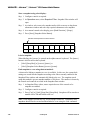
Text Conventions ................................................................................................................ 3
Chapter 1. Descriptions and Overview
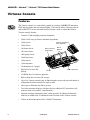
Virtuoso Console
Features ............................................................................................................................... 6
Components ........................................................................................................................ 7
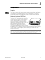
Console......................................................................................................................... 7
Network Interface (NIF) Unit....................................................................................... 7
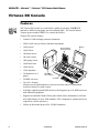
Virtuoso DX Console
Features ............................................................................................................................... 8
Components ........................................................................................................................ 9
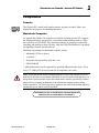
Console......................................................................................................................... 9
Macintosh Computer .................................................................................................... 9
Virtuoso DX Console Accessories List............................................................................. 10
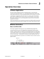
Operation Overview
Virtuoso Application ......................................................................................................... 11
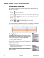
Window Interaction........................................................................................................... 11
Menus and Button Bar................................................................................................ 11
Entering/Editing Window Data .................................................................................. 12
Closing Windows ....................................................................................................... 12
Locating Hidden Windows......................................................................................... 12
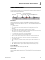
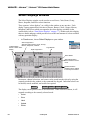
Status Indicator Bar........................................................................................................... 13
Arrange Monitors.............................................................................................................. 14
Chapter 2. Installation
Virtuoso Console
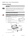
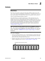
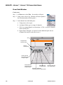
Overview........................................................................................................................... 16
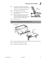
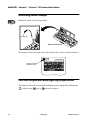
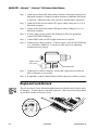
Unpacking Console Road Case......................................................................................... 16
Installing Desk Lamps ...................................................................................................... 18
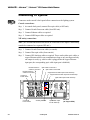
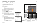
Pull-Out Keyboard Backlighting Adjustment................................................................... 18
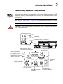
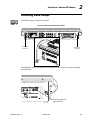
Connecting Optional Components.................................................................................... 19
Connecting To System ...................................................................................................... 20
02.9 651.00 01 C
23-Sep-02
xiii
VARI❋LITE® - VIRTUOSO™ / VIRTUOSO™ DX CONSOLE USER’S MANUAL
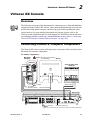
Virtuoso DX Console
Overview ..........................................................................................................................
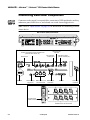
Connecting Console & Computer Components ...............................................................
Keyboard Lock/Unlock ....................................................................................................
Installing Desk Lamps......................................................................................................
Connecting Additional Components ................................................................................
21
21
22
23
24
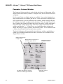
Chapter 3. Power-Up and Patch
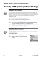
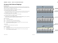
Power Up - DMX Systems (Virtuoso DX Only)
Powering Up Console.......................................................................................................
Powering Down Console..................................................................................................
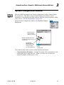
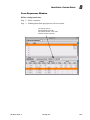
System Configuration Window ........................................................................................
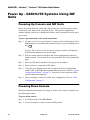
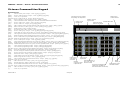
Power Up - VARI❋LITE Systems Using NIF Units
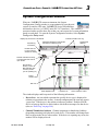
Powering Up Console and NIF Units...............................................................................
Powering Down Console..................................................................................................
System Configuration Window ........................................................................................
Console Naming.........................................................................................................
Store Configuration....................................................................................................
Update Configuration.................................................................................................
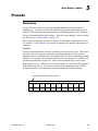
Patch
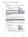
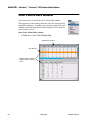
Overview ..........................................................................................................................
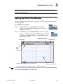
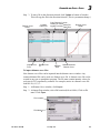
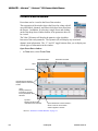
Setting Up Plan View Window.........................................................................................
Plan View Background Picture..................................................................................
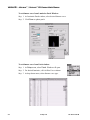
Patching DMX/Conventional Fixtures .............................................................................
Patching VARI❋LITE Series 300 Luminaires .................................................................
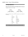
Dimmer Curves ................................................................................................................
Overview....................................................................................................................
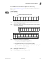
Dimmer Curves Window ...........................................................................................
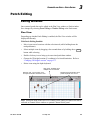
Patch Editing
Editing Windows ..............................................................................................................
Plan View...................................................................................................................
Patch...........................................................................................................................
2D/3D Mode Guidelines...................................................................................................
26
26
27
28
28
29
30
31
31
32
33
34
35
40
42
42
42
45
45
46
47
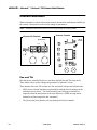
Chapter 4. Manual Control
Channel Select
Overview ..........................................................................................................................
Selecting Channels ...........................................................................................................
From Channel Select Window ...................................................................................
From Keypad .............................................................................................................
From Channel Select Panel........................................................................................
Channel Select Quick Buttons ...................................................................................
[Next] and [Last]........................................................................................................
xiv
23-Sep-02
50
50
51
53
54
56
56
02. 9651.0 001 C
TABLE OF CONTENTS
Lamp Control
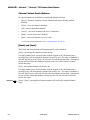
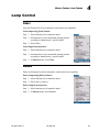
Start ................................................................................................................................... 57
Douse ................................................................................................................................ 57
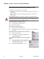
Reset/Recalibration/Erase Luminaire Data....................................................................... 58
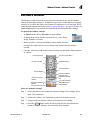
Encoder Control
Overview........................................................................................................................... 59
Console Encoders.............................................................................................................. 60
Pan and Tilt ................................................................................................................ 60
Intensity ...................................................................................................................... 61
Color........................................................................................................................... 61
Beam........................................................................................................................... 61
Image (Gobo) ............................................................................................................. 62
3D ............................................................................................................................... 62
Dynamic States........................................................................................................... 62
Frame (VL7B™ Luminaire Only) ............................................................................. 63
Storing New Default Min/Max Settings..................................................................... 64
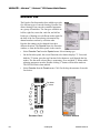
Encoders Window ............................................................................................................. 65
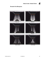
Encoder Fan ...................................................................................................................... 66
Encoder Fan Examples............................................................................................... 67
Keypad Control
Overview........................................................................................................................... 68
Setting Parameters From Keypad ..................................................................................... 69
Intensity ...................................................................................................................... 69
Presets......................................................................................................................... 69
Colors ......................................................................................................................... 69
Beams ......................................................................................................................... 70
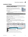
Luminaire Status
Luminaire Status Window ................................................................................................ 71
Parameter Columns Window...................................................................................... 72
Intensity Window .............................................................................................................. 73
Chapter 5. Select Displays
General Operation
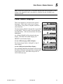
Overview........................................................................................................................... 76
What are Selects? ....................................................................................................... 76
Accessing Selects From Keypad ................................................................................ 76
Standard Beams and Colors ....................................................................................... 76
Panel Select Displays ....................................................................................................... 77
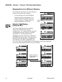
Mapping Selects to Different Displays ...................................................................... 78
[Palette Shift] Button
(Virtuoso DX)............................................................................................................. 78
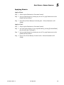
Applying Selects......................................................................................................... 79
02.9 651.00 01 C
23-Sep-02
xv
VARI❋LITE® - VIRTUOSO™ / VIRTUOSO™ DX CONSOLE USER’S MANUAL
Select Displays Window................................................................................................... 80
Store ........................................................................................................................... 81
Label .......................................................................................................................... 81
Update ........................................................................................................................ 81
Delete ......................................................................................................................... 82
Select.......................................................................................................................... 82
Beams
Overview .......................................................................................................................... 83
Beam Palette Data Window.............................................................................................. 84
Storing, Modifying, and Recalling Beams ....................................................................... 85
From Panel Select Displays ....................................................................................... 85
From Select Displays Window ................................................................................. 87
From Keypad ............................................................................................................. 87
Colors
Overview .......................................................................................................................... 89
Color Palette Data Window .............................................................................................. 90
Storing and Recalling Colors............................................................................................ 91
From Panel Select Displays ....................................................................................... 91
From Select Displays Window ................................................................................. 92
From Keypad ............................................................................................................. 92
Presets
Overview .......................................................................................................................... 93
Preset Data Window ......................................................................................................... 94
Storing, Modifying, and Recalling Presets....................................................................... 95
From Panel Select Displays ....................................................................................... 95
From Select Displays Window ................................................................................. 97
From Keypad ............................................................................................................. 97
Groups
Overview .......................................................................................................................... 99
Storing, Modifying, and Recalling Groups ...................................................................... 99
From Panel Select Displays ....................................................................................... 99
From Select Displays Window ............................................................................... 100
From Keypad ........................................................................................................... 100
From Group Select Panel (Virtuoso Console) ......................................................... 101
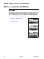
Macros, Snapshots, and Effects
Overview ........................................................................................................................ 102
xvi
23-Sep-02
02. 9651.0 001 C
TABLE OF CONTENTS
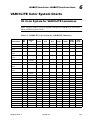
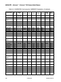
Chapter 6. VARI❋LITE Color System
Color Control
Overview......................................................................................................................... 104
VARI❋LITE Colors........................................................................................................ 104
Applying VARI❋LITE Colors
From VL Color System Window .................................................................................... 105
From Keypad .................................................................................................................. 106
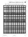
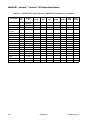
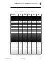
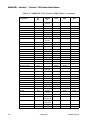
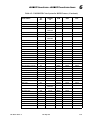
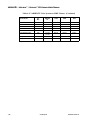
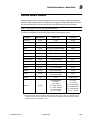
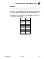
VARI❋LITE Color System Charts
VL Color System for VARI❋LITE Luminaires ............................................................. 107
VL Color System for DMX-Controllable Fixtures......................................................... 111
Chapter 7. Basic Cues
Cue Concepts
What Is a Cue? ................................................................................................................ 116
Creating Cues
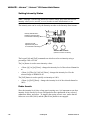
Intensity States ................................................................................................................ 117
The Four Intensity States.......................................................................................... 117
Setting Intensity States ............................................................................................. 118
Fader Levels ............................................................................................................. 118
Storing ............................................................................................................................ 119
Modifying ....................................................................................................................... 119
Deleting........................................................................................................................... 120
Undo................................................................................................................................ 120
Playback
Basic Playback ................................................................................................................ 121
Chapter 8. Basic Effects
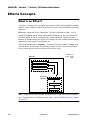
Effects Concepts
What is an Effect? ........................................................................................................... 124
Effects Control Panel and Windows ............................................................................... 125
Effects Control Panel (Virtuoso Console)................................................................ 125
Effects Control Panel (Virtuoso DX Console) ......................................................... 126
Effects Windows ...................................................................................................... 126
Direction, Mode, and Start.............................................................................................. 127
Direction................................................................................................................... 127
Mode......................................................................................................................... 128
Start .......................................................................................................................... 129
Default Settings ........................................................................................................ 129
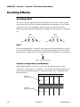
Creating Effects
Creating Sets ................................................................................................................... 130
Set 0.......................................................................................................................... 130
Interlace, Sequential, and Random........................................................................... 130
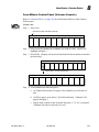
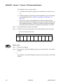
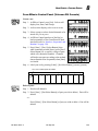
From Effects Control Panel (Virtuoso DX Console) ............................................... 133
From Sets Window................................................................................................... 134
02.9 651.00 01 C
23-Sep-02
xvii
VARI❋LITE® - VIRTUOSO™ / VIRTUOSO™ DX CONSOLE USER’S MANUAL
Creating Sequences ........................................................................................................
From Effects Control Panel (Virtuoso Console)......................................................
From Effects Control Panel (Virtuoso DX Console)...............................................
From Sequences Window ........................................................................................
Background State............................................................................................................
From Effects Select Displays (Virtuoso DX Console) ............................................
From Sequences Window ........................................................................................
Creating Effects ..............................................................................................................
From Keypad ...........................................................................................................
From Effects Select Display (Virtuoso Console).....................................................
From Effects Select Displays (Virtuoso DX Console) ............................................
From Effects Window..............................................................................................
Storing Effects as Cues...................................................................................................
Playback
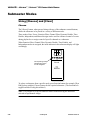
Basic Playback................................................................................................................
Submaster Display ...................................................................................................
136
137
138
140
141
142
143
144
144
145
146
147
148
149
150
Chapter 9. Timing/Filter Displays
Overview
Timing/Filter Features ....................................................................................................
General Touch Screen/Window Operations ...................................................................
Timing Mode
Overview ........................................................................................................................
Time/Speed Formats.......................................................................................................
Time .........................................................................................................................
Delay ........................................................................................................................
Speed........................................................................................................................
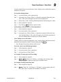
Timing Mode Operation .................................................................................................
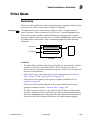
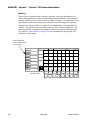
Filter Mode
Overview ........................................................................................................................
Filter Mode Operation ....................................................................................................
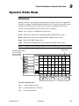
Dynamic State Mode
Overview ........................................................................................................................
Dynamic State Attributes ...............................................................................................
Storing Dynamic States as Cues/Presets ........................................................................
Palette: Store Dynamic Only ..........................................................................................
How To Store Dynamic Only Values ......................................................................
Sneak Mode
Overview ........................................................................................................................
Sneak Mode Values ........................................................................................................
Sneak Mode Operation ...................................................................................................
Templates
Creating Templates .........................................................................................................
From Timing Window .............................................................................................
From Template Select Display (Virtuoso Console).................................................
From Touch Screen (Virtuoso DX Console) ...........................................................
xvii i
23-Sep-02
152
152
154
155
155
155
156
156
159
161
163
164
165
166
167
168
169
170
172
172
172
173
02. 9651.0 001 C
TABLE OF CONTENTS
Chapter 10. Special Features
Ad Hoc Groups
Overview......................................................................................................................... 176
Creating Ad Hoc Groups ................................................................................................ 176
From Keypad............................................................................................................ 176
From Select Displays................................................................................................ 176
From Submasters...................................................................................................... 176
Advanced Control
Manual Timing................................................................................................................ 177
QuickFocus ..................................................................................................................... 177
Park ................................................................................................................................. 178
Data Copy and Move
Copy Channel.................................................................................................................. 179
Copy/Move ..................................................................................................................... 180
Copy Data ....................................................................................................................... 181
Function Keys
Setting Function Key Option .......................................................................................... 182
Using Function Keys....................................................................................................... 182
Chapter 11. Snapshots, Macros, and
Board Cues
Snapshots
Overview......................................................................................................................... 188
Storing Snapshots............................................................................................................ 189
Deleting Snapshots.......................................................................................................... 191
Recalling Snapshots ........................................................................................................ 191
Snapshot Data ................................................................................................................. 192
Macros
Overview......................................................................................................................... 193
Recording Macros........................................................................................................... 194
Using Record Button ................................................................................................ 194
From Keypad............................................................................................................ 195
From Encoders Window........................................................................................... 195
Macros Data Window ..................................................................................................... 196
Recalling Macros ............................................................................................................ 198
Board Cues
Overview......................................................................................................................... 199
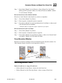
Recording Board Cues .................................................................................................... 200
Using Record Button ................................................................................................ 200
From Keypad............................................................................................................ 200
From Encoders Window........................................................................................... 201
Deleting Board Cues ....................................................................................................... 201
Recalling Board Cues ..................................................................................................... 202
Board Cues Window ....................................................................................................... 203
02.9 651.00 01 C
23-Sep-02
xix
VARI❋LITE® - VIRTUOSO™ / VIRTUOSO™ DX CONSOLE USER’S MANUAL
Chapter 12. Advanced Cue Features
Special Cue Attributes
Overview ........................................................................................................................
Link.................................................................................................................................
Loop................................................................................................................................
Wait/Trail Time...............................................................................................................
Out Time.........................................................................................................................
Advanced Cue Storing and Modifying
How Faders Affect Intensity ..........................................................................................
Grand Master/Black Out ..........................................................................................
Submaster Faders .....................................................................................................
Command-Line Shortcuts...............................................................................................
Using [+] with [Store]..............................................................................................
[Store] [Store] ..........................................................................................................
Submaster Load .......................................................................................................
Cue Store Target ......................................................................................................
Cue Attribute Target ................................................................................................
Miscellaneous Shortcuts ..........................................................................................
Creating Cue Numbers without Storing Data ..........................................................
Locating Stored Cues...............................................................................................
Update.............................................................................................................................
Selective Store ................................................................................................................
Selective Recall ..............................................................................................................
Undo a Delete Command ...............................................................................................
Modifying Cues in a Submaster .....................................................................................
Store, Update, and Selective Store with Submasters ...............................................
Unexpected Behavior...............................................................................................
Submaster Direct Mode..................................................................................................
Cue Windows
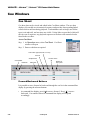
Cue Sheet........................................................................................................................
Forward/Backward Buttons .....................................................................................
Separators.................................................................................................................
Renumbering Cues...................................................................................................
Submasters Track Mode ..........................................................................................
Submasters Autoload ...............................................................................................
Submaster Stop/Step ................................................................................................
Snap Shot Indicator..................................................................................................
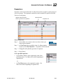
Cue Data .........................................................................................................................
Cue Editing ..............................................................................................................
xx
23-Sep-02
206
207
208
209
210
211
211
212
213
213
213
213
214
214
214
214
215
216
217
218
219
219
220
220
221
222
222
223
224
224
224
224
224
225
226
02. 9651.0 001 C
TABLE OF CONTENTS
Chapter 13. Advanced Effects Features
Advanced Attributes
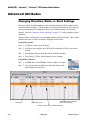
Changing Direction, Mode, or Start Settings.................................................................. 230
Effect Timing
Overview......................................................................................................................... 231
Effect Level Timing ........................................................................................................ 232
Assigning Effects Level Timing ..................................................................................... 233
From Select Displays................................................................................................ 233
From Effects Window .............................................................................................. 234
Sequence Level Timing .................................................................................................. 235
Assigning Sequence Level Timing ................................................................................. 236
From the Effects Panel (Virtuoso Console) ............................................................. 236
From Select Displays (Virtuoso DX Console) ......................................................... 236
From Sequences Window......................................................................................... 236
Advanced Playback
Stop Flags........................................................................................................................ 237
Auto Load ....................................................................................................................... 238
Run/Stop Control ............................................................................................................ 239
Chapter 14. Submasters
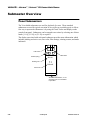
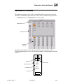
Submaster Overview
Panel Submasters ............................................................................................................ 242
Submasters Window ....................................................................................................... 243
Submaster Modes
Using [Choose] and [Clear] ............................................................................................ 244
Choose ...................................................................................................................... 244
Clear ......................................................................................................................... 245
Rate ................................................................................................................................. 245
Freeze.............................................................................................................................. 246
Function Filter................................................................................................................. 246
Channel Filter.................................................................................................................. 247
Dynamic Disable............................................................................................................. 247
Timing Disable................................................................................................................ 248
Independent..................................................................................................................... 248
Manual Assign ................................................................................................................ 249
Intensity Level with Manual Assign ........................................................................ 250
Bump............................................................................................................................... 250
Board Command Disable................................................................................................ 251
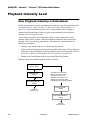
Playback Intensity Level
How Playback Intensity is Determined........................................................................... 252
Example Scenarios.......................................................................................................... 253
Intensity Transitions........................................................................................................ 254
HTP (Highest Takes Precedence) ................................................................................... 254
02.9 651.00 01 C
23-Sep-02
xxi
VARI❋LITE® - VIRTUOSO™ / VIRTUOSO™ DX CONSOLE USER’S MANUAL
Playback
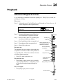
Advanced Playback of Cues........................................................................................... 255
Controlling Linked Playback.......................................................................................... 256
Fade Times for Marked/Zero/Out Cues.......................................................................... 256
Chapter 15. System Setups
Default Options
Settings Window.............................................................................................................
Default Explanations ......................................................................................................
Emergency Action ...................................................................................................
Startup Action ..........................................................................................................
Date/Time Stamp .....................................................................................................
Units.........................................................................................................................
Palette Store Options................................................................................................
Use of Filters with Color Store ................................................................................
Buttons/Keys............................................................................................................
Timecode Autoswitch ..............................................................................................
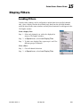
Display Filters
Loading Filters................................................................................................................
Multi-Console Features
Setting Up a Backup Console.........................................................................................
Primary and Secondary Setups ................................................................................
Online Backup .........................................................................................................
Power Up .................................................................................................................
Configuring Multiple Consoles................................................................................
Connecting Virtuoso DX Backup in Standard Ethernet Systems...................................
Disable Console..............................................................................................................
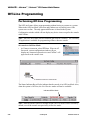
Off-Line Programming
Performing Off-Line Programming................................................................................
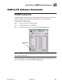
VARI❋LITE Software Downloads
VL2000 Luminaires........................................................................................................
258
259
259
259
259
259
259
260
260
260
261
262
262
262
263
263
264
265
266
267
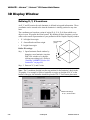
Chapter 16. 3D Graphic Display
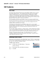
3D Features
Overview ........................................................................................................................
Defining a New Venue....................................................................................................
Importing a Venue ..........................................................................................................
3D Layer Control .....................................................................................................
Exporting a Scene...........................................................................................................
Match 3D ........................................................................................................................
3D Display Window
Defining X, Y, Z Locations ............................................................................................
Changing 3D Height Location .................................................................................
Using 3D Graphic Window ............................................................................................
3D Graphic Settings .......................................................................................................
xxii
23-Sep-02
270
270
271
272
272
273
274
275
276
278
02. 9651.0 001 C
TABLE OF CONTENTS
Live/Preview Mode
Overview......................................................................................................................... 279
Using Preview Mode....................................................................................................... 280
Chapter 17. Show Maintenance
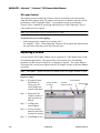
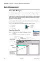
Data Management
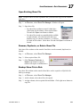
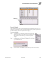
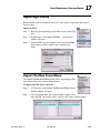
Show File Manager ......................................................................................................... 282
Open New Show File ............................................................................................... 282
Open Existing Show File.......................................................................................... 283
Rename, Duplicate, or Delete Show File ................................................................. 283
Backup Show File to Disk........................................................................................ 283
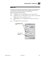
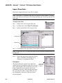
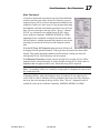
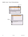
Import Show Data .................................................................................................... 284
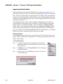
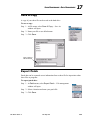
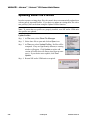
Importing Palette Data.............................................................................................. 286
Save A Copy ................................................................................................................... 289
Export Patch.................................................................................................................... 289
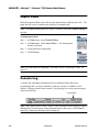
Import Patch.................................................................................................................... 290
Console Log .................................................................................................................... 290
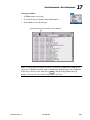
Printing............................................................................................................................ 292
Updating Profiles
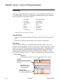
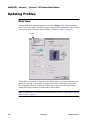
Overview......................................................................................................................... 294
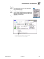
Importing Profiles ........................................................................................................... 295
Import Profiles From Show ............................................................................................ 295
Updating Show File Profiles........................................................................................... 296
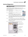
On-Line Diagnostics
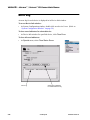
DMX Channel Tests........................................................................................................ 297
Error Log......................................................................................................................... 298
Off-Line Diagnostics
Overview......................................................................................................................... 299
Diagnostic Mode Operation (Virtuoso Console) ............................................................ 299
Switch Diagnostics ................................................................................................... 299
Display Diagnostics.................................................................................................. 299
Fader and Encoder Diagnostics................................................................................ 299
Diagnostic Mode Operation (Virtuoso DX Console)...................................................... 302
Chapter 18. Show Control by External Devices
Concepts
About MIDI/SMPTE....................................................................................................... 304
Input Options .................................................................................................................. 305
MIDI In/Thru/Out..................................................................................................... 305
SMPTE Input............................................................................................................ 305
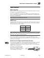
Switch Closure Trigger Input (Virtuoso Console) ................................................... 305
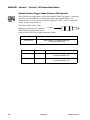
Switch Closure Trigger Input (Virtuoso DX Console) ............................................ 306
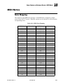
MIDI Notes
Note Mapping ................................................................................................................. 307
02.9 651.00 01 C
23-Sep-02
xxiii
VARI❋LITE® - VIRTUOSO™ / VIRTUOSO™ DX CONSOLE USER’S MANUAL
MIDI/SMPTE Timecode
Overview ........................................................................................................................
Synchronizing Protocol............................................................................................
Recording .......................................................................................................................
Timecode Scripts Window.......................................................................................
MIDI Show Control
Overview ........................................................................................................................
Variables ..................................................................................................................
Commands ...............................................................................................................
Defined [Go] Actions...............................................................................................
309
309
310
311
314
315
316
317
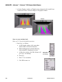
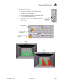
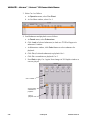
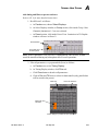
Appendix A. Tutorial
Overview ........................................................................................................................ 319
Basic Tutorial ................................................................................................................. 320
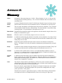
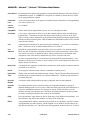
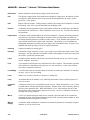
Appendix B. Glossary
......................................................................................................................................... 337
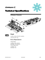
Appendix C. Technical Specifications
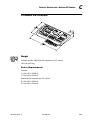
Virtuoso Console ............................................................................................................
Weight......................................................................................................................
Power Requirements ................................................................................................
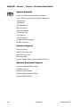
System Capacity.......................................................................................................
Interface Support......................................................................................................
Optional Equipment Support ...................................................................................
Virtuoso DX Console .....................................................................................................
Weight......................................................................................................................
Power Requirements ................................................................................................
System Capacity.......................................................................................................
Interface Support......................................................................................................
Optional Equipment Support ...................................................................................
347
347
347
348
348
348
349
349
349
350
350
350
Appendix D. Index
......................................................................................................................................... 351
xxiv
23-Sep-02
02. 9651.0 001 C
TABLE OF CONTENTS
Appendix E. Reference Fold-Outs
Virtuoso Console Overview .................................................................................................. 359
Virtuoso Channel Select ........................................................................................................ 360
Virtuoso Group Select ........................................................................................................... 361
Virtuoso Manual Control....................................................................................................... 362
Virtuoso Soft Select Displays................................................................................................ 363
Virtuoso Command-Line Keypad ......................................................................................... 364
Virtuoso Submasters.............................................................................................................. 365
Virtuoso Effects..................................................................................................................... 366
Virtuoso Touch Screen & Macro/Snapshot/Template Display ............................................. 367
Virtuoso DX Console Overview ........................................................................................... 368
Virtuoso DX Console Connections ....................................................................................... 369
Virtuoso DX Channel Select/Lamp Status ............................................................................ 370
Virtuoso DX Manual Control................................................................................................ 371
Virtuoso DX Select Displays................................................................................................. 372
Virtuoso DX Command-Line Keypad................................................................................... 373
Virtuoso DX Submasters....................................................................................................... 374
Virtuoso DX Timing/Filter Display ...................................................................................... 375
02.9 651.00 01 C
23-Sep-02
xxv
VARI❋LITE® - VIRTUOSO™ / VIRTUOSO™ DX CONSOLE USER’S MANUAL
Notes
xxvi
23-Sep-02
02. 9651.0 001 C
INTRODUCTION : ABOUT THIS MANUAL
Introduction
About This Manual
This manual provides necessary information regarding product safety, installation, and
operation for VARI❋LITE® Virtuoso™ and Virtuoso™ DX consoles. It contains
instructions for operating Virtuoso console software version 4.2.
WARNING: It is important to read ALL accompanying safety and installation
instructions to avoid damage to the product and potential injury to yourself or others.
Additional Documentation
Service and System Installation
Service manuals for extended maintenance of the consoles and a system installation
manual for Virtuoso systems are available in both printed and electronic (PDF)
formats.
•
Virtuoso™ Console Service Manual (02.9651.0010)
•
Virtuoso™ DX Console Service Manual (02.9668.0010)
•
Virtuoso™ System Installation and Checkout Manual (02.3004.0400)
•
Virtuoso™ Node User’s Guide (02.9669.0001)
Reference
The following VARI❋LITE reference guide is available in electronic (PDF) format
from the Support pages at www.vari-lite.com:
•
Series 200™ DMX Control Reference Guide (02.3004.0202)
For more information on DMX512 systems, refer to the following document available
from United States Institute for Theatre Technology, Inc. (USITT).
•
02.9 651.00 01 C
Digital Data Transmission Standard for Dimmers & Controllers plus AMX 192
Analog Multiplex Data Transmission Standard for Dimmers & Controllers. (A
copy of Recommended Practice for DMX512 is included.)
USITT Inc.
Suite 5A, 10 West 19th St.
New York, NY 10011-4206 USA
Tel : (212) 924 - 9088 Fax : (212) 924 - 9343
www.usitt.org
23-Sep-02
1
VARI❋LITE® - VIRTUOSO™ / VIRTUOSO™ DX CONSOLE USER’S MANUAL
Customer Service
Our Goal
At Vari-Lite, we are committed to providing you the highest quality in customer
service. Our comprehensive resources are available to help your business succeed and
ensure you get the full benefit of being a Vari-Lite customer. Whether your needs are
telephone/troubleshooting assistance, product training or technical service, our fulltime staff of experienced professionals are on-hand to provide support.
How to Reach Us
For assistance in your area, call the dealer from which your product(s) were
purchased.
or
Contact an Authorized Service Center.
or
Contact the Vari-Lite Customer Service Department, 9am - 6pm CST Monday through
Friday, at the following:
phone: 1-877-VARI-LITE (1-877-827-4548)
fax: 214.630.5867
email: [email protected]
Additional Resources
For additional resources and documentation, please visit our website at:
www.vari-lite.com and follow the Support link.
Obtaining Additional DMX Profiles
DMX fixtures are controlled by the console using a profile. The profile includes the
number of DMX channels required to operate the fixture and parameter mapping for
console control. A wide range of profiles are included with the console software,
however, in the event you require additional profiles these can be found on the VariLite website at: www.vari-lite.com/VIPA/. Follow the instructions at this site for
downloading. To request a profile not provided on the website, please call 1-877VARI-LITE (1-877-827-4548) or email [email protected]. Please be prepared
to provide the necessary information to generate the profile as required. (Profiles are
covered in “Updating Profiles” on page 294.)
2
23-Sep-02
02. 9651.0 001 C
INTRODUCTION : TEXT CONVENTIONS
Text Conventions
The following styles and meanings are used throughout this manual:
Arial Font
Software display buttons and menu selections. Example: Click on SAVE.
[Button]
Panel hard button. Example: Press [Cue].
[Button 1 ] / [Button 2]
Button combination sequence. Press and
hold button 1while pressing button 2.
<Button>
Optional button press. Example: Press
<Cue>
Soft
return
Touch screen soft button.
Macintosh® keyboard key.
The following icons are used to distinguish instructions which apply to the specific
console versions:
Virtuoso Console
Virtuoso DX Console
DX
02.9 651.00 01 C
23-Sep-02
3
VARI❋LITE® - VIRTUOSO™ / VIRTUOSO™ DX CONSOLE USER’S MANUAL
Notes
4
23-Sep-02
02. 9651.0 001 C
CHAPTER 1.
Descriptions and Overview
This chapter provides an overview of console features, accessories, and operations.
• Virtuoso Console
• Virtuoso DX Console
• Operation Overview
02.9 651.00 01 C
23-Sep-02
5
VARI❋LITE® - VIRTUOSO™ / VIRTUOSO™ DX CONSOLE USER’S MANUAL
Virtuoso Console
Features
The Virtuoso console is a control desk capable of operating VARI❋LITE luminaires,
DMX moving lights, and conventional lights. The console utilizes Virtuoso protocol
and/or DMX512 (via an associated Network Interface unit) to control the fixtures.
Virtuoso console features:
6
•
Control of 2,000 multiple parameter luminaires.
•
2,000-10,000 cues per fixture (luminaire dependent).
•
1,000 presets.
•
1,000 effects.
•
100 beam selects.
•
300 color selects.
•
1000 group selects.
•
1,000 board cues.
•
1,000 macros.
•
1,200 snapshots.
•
30 submasters (in 3 pages).
•
Zip® drive for show file
backup.
•
CD ROM drive for software upgrades.
•
Built-in hard drive for show file storage.
•
Up to five Virtuoso consoles may be linked together to provide universal shared or
independent localized control of a single system.
•
Fiber optic or Ethernet data link to system.
•
Two built-in monitor displays with ports for two additional VGA monitors. (All
monitors form one seamless, virtual monitor.)
•
Optional Auxiliary Submasters panel, which provides 20 additional submaster
faders to be added to the 10 submasters faders located on the Virtuoso console.
•
Utilizes bi-directional protocol for VL2000™ luminaires.
Auxiliary Submasters
Panel (optional)
Built-in Channel
Select Panel
Built-in
Monitors
Console
23-Sep-02
Built-in Keyboard
02. 9651.0 001 C
DESCRIPTIONS AND OVERVIEW : VIRTUOSO CONSOLE
1
Components
Console
The Virtuoso console itself contains buttons, keypads, encoders, faders, and displays
for the purpose of controlling luminaires. A built-in Macintosh CPU, keyboard,
trackpad and monitors allows integration of menu and window based commands.
Network Interface (NIF) Unit
The Series 300™ Network Interface unit (NIF) is
used in association with the Virtuoso console to
control a lighting system. Power for both the
console(s) and Series 300 luminaires (except
lamp power) is distributed from the NIF unit. All
data communication from the console to
luminaires passes through the NIF unit for
processing and distribution into Virtuoso protocol
and DMX512 protocol. Although a single NIF unit can support two Virtuoso consoles,
a single console can control lighting systems utilizing up to 99 NIF units when
arranged in a data loop.
Note: For more detailed installation and operation instructions for the NIF unit, refer
to the Virtuoso System Installation and Checkout Manual (02.3004.0400)
02.9 651.00 01 C
23-Sep-02
7
VARI❋LITE® - VIRTUOSO™ / VIRTUOSO™ DX CONSOLE USER’S MANUAL
Virtuoso DX Console
Features
DX
The Virtuoso DX console is a control desk capable of operating VARI❋LITE
luminaires, DMX moving lights, and conventional lights. The console utilizes
Virtuoso protocol and/or DMX512 to control the fixtures.
Virtuoso DX console features:
8
•
Control of 2,000 multiple parameter luminaires.
•
2,000-10,000 cues per fixture (luminaire dependent).
•
1,000 presets.
•
1,000 effects.
•
100 beam selects.
•
300 color selects.
•
1000 group selects.
•
1,000 board cues.
•
1,000 macros.
•
1,200 snapshots.
•
30 submasters (in 3
pages).
•
26 DMX universes.
•
Up to five Virtuoso
consoles may be linked together to provide universal shared or independent
localized control of a single system.
•
It includes eight integrated DMX universes and supports up to 26 DMX universes
with additional equipment.
•
Supports an outboard Channel Select panel which allows instantaneous selection
and visible display of up to 2000 channels. (This component is optional and is not
required for console operation.)
•
Utilizes bi-directional protocol for VL2000 luminaires.
Channel Select
Panel (optional)
Monitor
Macintosh
G4 Computer
Console
23-Sep-02
02. 9651.0 001 C
DESCRIPTIONS AND OVERVIEW : VIRTUOSO DX CONSOLE
1
Components
Console
The Virtuoso DX console itself contains buttons, keypads, encoders, faders, and
displays for the purpose of controlling luminaires.
DX
Macintosh Computer
An Apple® Macintosh® G4 computer provides the operating system CPU, supports
the display monitor(s), and provides a removable backup medium (such as a Zip®
drive) and CD or DVD ROM. The removable medium is primarily for importing,
exporting, and backing up show file data, while the CD/DVD ROM drive is primarily
for upgrading Virtuoso console software.
Minimum requirements for Macintosh computer system:
•
Macintosh G4 OS9 or greater
•
A monitor *
•
Removable backup medium (Zip drive, etc.)
•
CD/DVD-ROM
* Additional monitors can be supported by installing additional video cards. Please
call 1-877-VARI-LITE for most recent list of compatible video cards.
Note: Some Macintosh monitors shipped with the Virtuoso DX console have been
modified so that their power button is disabled. It has been discovered that there is a
design defect for this product where the button can be remotely activated by cellular
phone activity, resulting in shutdown of the Macintosh computer system during
console operation. The following sticker applied to the back of the monitor indicates
whether the power button has been disabled:
THE POWER BUTTON ON THIS MONITOR HAS BEEN DISABLED
SEE VIRTUOSO DX USERS MANUAL FOR DETAILS
02.9 651.00 01 C
23-Sep-02
9
VARI❋LITE® - VIRTUOSO™ / VIRTUOSO™ DX CONSOLE USER’S MANUAL
Virtuoso DX Console Accessories List
The following accessories and/or replacement items can be ordered directly from VariLite. (Please order by Vari-Lite part number.)
DX
Vari-Lite Part No.
Accessory
10.9668.0130
CONSOLE DUST COVER
20.9625.0142
CONSOLE ROAD CASE
20.9625.0143
MACINTOSH COMPUTER ROAD CASE
21.9668.0005
CHANNEL SELECT PANEL
52.6616.0780
MINI PHONE .141" MONO SHIELDED
2-COND SOLDER PLUG
71.5001.0003
GOOSENECK HI-INTENSITY DESK LAMP
call for details
MACINTOSH MONITOR
call for details
AUXILIARY MONITOR VIDEO CARD
The following accessories can be purchased from Vari-Lite or on the open market as
required.
10
Manufacturer
Part No.
Accessory
Switchcraft
780
MINI PHONE .141" MONO SHIELDED
2-COND SOLDER PLUG
Digi-Key
SC1057-ND
MINI PHONE .141" MONO SHIELDED
2-COND SOLDER PLUG
23-Sep-02
02. 9651.0 001 C
DESCRIPTIONS AND OVERVIEW : OPERATION OVERVIEW
1
Operation Overview
Virtuoso Application
The same Virtuoso application (software operating system) is used in both the
Virtuoso and Virtuoso DX consoles. As a result, the Macintosh-based windows and
menus operate identically. The only operational difference between these two consoles
is the hardware configuration of the desk itself. For example, if the Channel Select
panel (which is standard for the Virtuoso console) is not available on your Virtuoso
DX console, channels can be selected using another method such as the Macintosh
Channel Select window.
For the most part however, the consoles are operated very similarly and the operational
instructions provided in this manual will apply to all versions unless otherwise noted.
Window Interaction
Menus and Button Bar
The Virtuoso application functions just as any standard Macintosh application.
A menu bar provides access to file management commands and Virtuoso system
windows. Virtuoso windows can also be accessed using the button bar at the bottom
of each installed monitor screen. Clicking the soft button with the cursor will open the
window (in the event it is closed), bring it to the front (if already open, but hidden), or
close it (if in the front). Clicking the far-left button (with the underlined name) will
page through the button bars to provide access to different Virtuoso windows and navigation controls.
Button bar
Click to page
through button bars
02.9 651.00 01 C
23-Sep-02
11
VARI❋LITE® - VIRTUOSO™ / VIRTUOSO™ DX CONSOLE USER’S MANUAL
Entering/Editing Window Data
The Macintosh keyboard can be used to type in alpha-numeric entries or select cells
and fields in the windows.
•
Pressing
e
n
t
e
r
•
Pressing
return
•
Pressing
editing.
Shift
•
Pressing
tab
•
Pressing
Shift
•
Use arrow buttons to move cursor through fields.
closes the entry field.
automatically selects the next cell down in the column for editing.
/
return
automatically selects the next cell up in the column for
selects the next cell or field in a row.
/
tab
selects the previous cell or field in a row.
The trackpad can be used to manipulate the cursor for field/cell editing, clicking radio
buttons, accessing pop-up menus, moving windows, or closing windows.
Closing Windows
As with any Macintosh application, windows can be closed by
clicking the box in their left-hand corner. Windows can also be
closed from the File menu by selecting Close Window.
Locating Hidden Windows
When windows are open but hidden, use the Windows menu to
locate and bring to the front.
To bring window to front:
•
At menu bar select the Windows menu, click on any window
to make it the front active widow.
Note: A checkmark will show which window is currently the
top active window.
12
23-Sep-02
02. 9651.0 001 C
DESCRIPTIONS AND OVERVIEW : OPERATION OVERVIEW
1
Status Indicator Bar
Several indicators available at the lower portion of the screen provide an indication of
current console status and operations.
Patch Edit Enabled/Disabled
Current Showfile
Status / State
Patch On/Off
Live/Preview/Offline Mode
Log Messages
Status/State
Indicates the console state or status in relationship to communication between the
Macintosh CPU and Console Interface Card (CIC). The following indications may be
displayed:
•
P - Primary console.
•
PP - Primary Prep: where the Mac opens the show file and initializes the CIC for
downloads.
•
PL - Primary Load: where the show file is loaded to the CIC and Mac.
•
PS - Primary Select: where a show file back up is being made or other action is occurring
where the CIC is not immediately available for changes.
•
U - Unknown state: where the CIC is no longer responding.
•
** - No CIC reply: where the CIC is not available or ready.
•
NL - Net Listen: where the console checks for other active consoles on the network.
•
ML - Mac Listen: where the CIC checks for a local Mac. (Not usually displayed.)
•
S - Secondary console.
•
SP - Secondary Prep: where the secondary console syncs the show file and saves it to
disk.
•
SL - Secondary Load: where the secondary console loads the show file to the CIC.
•
WP - Waiting for Primary: appears while the Waiting For Primary Dialog is open.
Current Showfile
Displays the name of the currently open show file.
Patch On/Off
Indicates whether patch is turned on or off. (Patch On/Off will be covered in the next
chapter.)
02.9 651.00 01 C
23-Sep-02
13
VARI❋LITE® - VIRTUOSO™ / VIRTUOSO™ DX CONSOLE USER’S MANUAL
Patch Edit Enabled/Disabled
"Patch Edit" is displayed when patch is enabled from the Patch menu.
The box is blank when patch editing is disabled from the Patch menu.
Live/Preview/Offline Mode
Indicates whether the console is in the Live, Preview or Offline mode.
Live
PreView
The Live Mode is used for live editing. While the [Live] button is selected, any
manual control actions or event recalls (cues, effects, dynamic states, etc.) will be
executed, in real time, on stage.
The Preview Mode is used for preview editing. While the [Preview] button is
selected, any manual control actions are stored to the appropriate luminaires, but are
not executed on stage.
Refer to “Live/Preview Mode” on page 279 for complete instructions on these modes.
The Offline Mode allows preprogramming without having to connect to a system.
Refer to “Off-Line Programming” on page 266.
Log Messages
Messages highlighting in the Log Message box are the same messages collected in the
Console Log (refer to “Console Log” on page 290).
Arrange Monitors
The Arrange Monitors option arranges the monitors from left
to right according to the PCI order, sets size of monitors to
800x600 and sets the start up monitor and menu bar for
Monitor 1.
Select Arrange Monitors from the menu to activate.
14
23-Sep-02
02. 9651.0 001 C
CHAPTER 2.
Installation
This chapter provides instructions for installing a Virtuoso console and connecting
additional components.
• Virtuoso Console
• Virtuoso DX Console
02.9 651.00 01 C
23-Sep-02
15
VARI❋LITE® - VIRTUOSO™ / VIRTUOSO™ DX CONSOLE USER’S MANUAL
Virtuoso Console
Overview
The following section provides instructions for connecting power, data and additional
components to the Virtuoso console. These instructions pertain only to the console
itself and do not provide details regarding the entire system hook-up. For more
detailed information on Virtuoso systems, refer to the Virtuoso System Installation
and Checkout Manual (02.3004.0400).
Unpacking Console Road Case
CAUTION: The Virtuoso console and case weighs approximately 400 lbs (182 kg)
and requires a minimum of two people for unpacking.
Unpack console case:
Step 1. Place console case on its side (as shown).
Step 2. Unlatch all latches.
Step 3. Remove case lid and set aside.
Step 4. Pull table partway out of case, raise legs, and
lock into place.
Step 5. Remove table and set upright on flat surface. Ensure that legs are properly
locked and will support weight of console.
Cable storage
Wedge
Auxiliary
Submasters Panel
(not required)
Table
Tilt monitors 45 degrees
before sliding bar forward.
Support Bar
Console
Step 6. Remove wedge and set aside.
16
23-Sep-02
02. 9651.0 001 C
INSTALLATION : VIRTUOSO CONSOLE
Step 7. At console, loosen monitors by flipping
locking bar and reposition monitors at about a
45 degree angle, retightening locking bars.
2
Monitor
Locking Bar
Step 8. Slide support bar to front of case.
Step 9. If included, remove auxiliary submasters
panel and set aside.
Step 10. Using at least two people, remove console
from case and place securely on table
(removing console will require one person to
stand in case in order to lift properly).
Step 11. Remove dust cover.
Note: Recover console when powered down and not in use.
Bar slides forward
Dust Cover
Step 12. Remove cables from wedge compartment and place wedge back inside case.
Step 13. Re-attach case lid and set case aside.
Step 14. Re-adjust console monitors as desired.
02.9 651.00 01 C
23-Sep-02
17
VARI❋LITE® - VIRTUOSO™ / VIRTUOSO™ DX CONSOLE USER’S MANUAL
Installing Desk Lamps
Install desk lamps at console front panel.
Desk Lamp
Virtuoso Front Panel
The intensity of the desk lamps can be adjusted from the console’s pull-out keyboard.
Desk lamp intensity
adjustment knob
Pull-Out Keyboard Backlighting Adjustment
The intensity of the pull-out keyboard backlighting can be adjusted by holding down
FN , while pressing
(up) or
(down) as required.
18
23-Sep-02
02. 9651.0 001 C
INSTALLATION : VIRTUOSO CONSOLE
2
Connecting Optional Components
Connectors at the console’s rear panel allow connection of additional monitors, USB
peripherals, auxiliary submasters panel, MIDI devices, and a board cue switch closure
trigger device.
Note: Refer to “Input Options” on page 305 for information on constructing a switch
closure device.
CAUTION: Monitor power outlets are not always 110VAC. Outlets supply 208VAC
in U.S. on a Delta system.
Additional VGA monitor ports (2)
Fuse holders
110/220VAC outlets for monitors (2)
MIDI connections for prerecorded music synchronizing
Trigger contact closure
for use w/ external board
cue triggering device
In
For Future Use
Thru Out
For Future Use
USB accessory connections
(printer, mouse, etc.)
Main power
breaker
Auxiliary Submasters
panel connections
Ethernet connection
to NIF unit
Optic fiber connection
to NIF unit
02.9 651.00 01 C
23-Sep-02
Neutrik Powercon
AC input from NIF unit
19
VARI❋LITE® - VIRTUOSO™ / VIRTUOSO™ DX CONSOLE USER’S MANUAL
Connecting To System
Connectors at the console’s back panel allow connection to the lighting system.
Console connections:
Step 1. At console back panel, connect fiber optic cable (to NIF unit).
Step 2. Connect Neutrik Powercon cable (from NIF unit).
Step 3. Connect Ethernet cables as required.
Step 4. Connect MIDI input cables as required.
NIF unit(s) connections:
Note: (It is recommended that main console be connected to NIF inputs A and backup
console be connected to a separate NIF unit.)
Step 1. Connect Neutrik Powercon cable (to console).
Step 2. Connect fiber optic cable (from console).
Step 3. Connect NIF data loop cables as required. These can be either optic cables or
copper Ethernet cables in any combination as long as only one input and only
one output is used (e.g. when a cable is plugged into the copper Ethernet
input port, the corresponding optic cable input port is disabled).
Optic cable to Console A
Neutrik Powercon
outlet for Console A
Optic cable to Console B
Neutrik Powercon
Copper Ethernet cable input for NIF data loop
outlet for Console B
Copper Ethernet cable output for NIF data loop
Console A
Power switch
Console B
Power switch
20
Optic cable input for NIF data loop
Auxiliary Ethernet
23-Sep-02
Optic cable output
for NIF data loop
NIF Unit
(w/ Copper Mod)
02. 9651.0 001 C
INSTALLATION : VIRTUOSO DX CONSOLE
2
Virtuoso DX Console
Overview
DX
The following section provides instructions for connecting power, data and additional
components to the Virtuoso DX console. These instructions pertain only to the console
and associated Macintosh computer, and do not provide details regarding the entire
system hook-up. For more detailed information on Virtuoso systems, refer to the
Virtuoso System Installation and Checkout Manual (02.3004.0400). (For instructions
on configuring multiple consoles in a standard Ethernet system, refer to “Connecting
Virtuoso DX Backup in Standard Ethernet Systems” on page 264.)
Connecting Console & Computer Components
The Virtuoso DX console system will require inter-connection of the console desk and
Macintosh G4 computer components.
To connect components:
Macintosh
Computer
Caution: Set voltage selector switch
to proper setting.
Monitor
Channel Select Panel
(optional)
FireWire
USB
To Power
To Optional
Secondary Monitor
Monitor Power/Data
Power Cable
FireWire
DX Console
*
To Power
Expansion Connectors
* Note: Any of the three Aux ports can be used to connect the Channel Select panel.
02.9 651.00 01 C
23-Sep-02
21
VARI❋LITE® - VIRTUOSO™ / VIRTUOSO™ DX CONSOLE USER’S MANUAL
Step 1. Connect power/data cable from primary monitor to first (top) monitor port at
Macintosh computer. (Connect secondary monitors to additional video ports
as required. Additional video cards will not be installed unless requested.)
Step 2. Connect FireWire® from console CPU port to either comm port (1 or 2) at
Macintosh computer.
Step 3. Connect USB cable from console USB port to either USB port (1 or 2) at
Macintosh computer.
Step 4. If used, connect system comm cable (Ethernet or Fiber) to appropriate
console SYSTEM COMM port.
Step 5. Connect DMX cables to DMX output connectors as required.
Step 6. Connect power cable to console. (Console requires: 2.0 A at 120 V 50/60 Hz
or 1.0 A at 240 V 50/60 Hz). Lock power cable in place by tightening
retaining bracket as shown.
Tighten screw to
lock in place
Retaining Bracket
Step 7. Connect power cable to computer. Ensure that voltage selector switch on
back of computer is set correctly.
Step 8. If applicable, connect Channel Select FireWire and power cables to console.
Keyboard Lock/Unlock
DX
The pull-out drawer for the Macintosh alpha-numeric keyboard can be locked in place
for transport. To unlock drawer, turn knob clockwise. (Once drawer has been pushed
in, turn knob counter-clockwise to lock.)
To Unlock
22
23-Sep-02
02. 9651.0 001 C
INSTALLATION : VIRTUOSO DX CONSOLE
2
Installing Desk Lamps
Install desk lamps at console rear panel.
DX
Virtuoso DX Console (Desk) Rear Panel
MFR Date:
TM
VIRTUOSO DX CONTROL CONSOLE
Input Rating:
100−240VAC, 50/60 Hz 2A
R
CONFORMS TO
UL STD 508
CERTIFIED TO
C
LI
ST E
D
2000851
US CSA C22.2 No.14
TYPE 1 ENCLOSURE
201 REGAL ROW
DALLAS, TX. 75247 U.S.A.
1.877.VARILITE
WWW.VARI−LITE.COM
Serial Number:
CAUTION: Hazard of electrical shock. Disconnect power before servicing.
Servicing by qualified personnell only. Refer to service manual before
operating or servicing product. NOT FOR RESIDENTIAL USE.
ATTENTION: Couper Le Courant avant D’entretenir.
THIS DEVICE COMPLIES WITH PART 15 OF THE FCC RULES. OPERATION IS SUBJECT TO
THE FOLLOWING TWO CONDITIONS: (1) THIS DEVICE MAY NOT CAUSE HARMFUL
INTERFERENCE, AND (2) THIS DEVICE MUST ACCEPT ANY INTERFERENCE RECEIVED,
INCLUDING INTERFERENCE THAT MAY CAUSE UNDESIRED OPERATION.
Desk Lamp
Desk Lamp
Connector
Desk Lamp
Connector
The brightness of the desk lamps can be adjusted at the console rear panel using the
intensity knob.
Desk Lamp Brightness
Adjustment Knob
02.9 651.00 01 C
23-Sep-02
23
VARI❋LITE® - VIRTUOSO™ / VIRTUOSO™ DX CONSOLE USER’S MANUAL
Connecting Additional Components
Connectors at the console’s rear panel allow connection of USB peripherals, auxiliary
submasters panel, MIDI devices, and a board cue switch closure trigger device.
DX
Note: Refer to “Input Options” on page 305 for information on constructing a switch
closure device.
DX Console (Desk) Rear Panel
MFR Date:
TM
VIRTUOSO DX CONTROL CONSOLE
Input Rating:
100−240VAC, 50/60 Hz 2A
R
C
S T ED
Serial Number:
THIS DEVICE COMPLIES WITH PART 15 OF THE FCC RULES. OPERATION IS SUBJECT TO
THE FOLLOWING TWO CONDITIONS: (1) THIS DEVICE MAY NOT CAUSE HARMFUL
INTERFERENCE, AND (2) THIS DEVICE MUST ACCEPT ANY INTERFERENCE RECEIVED,
INCLUDING INTERFERENCE THAT MAY CAUSE UNDESIRED OPERATION.
CERTIFIED TO
LI
2000851
201 REGAL ROW
DALLAS, TX. 75247 U.S.A.
1.877.VARILITE
WWW.VARI−LITE.COM
CAUTION: Hazard of electrical shock. Disconnect power before servicing.
Servicing by qualified personnell only. Refer to service manual before
operating or servicing product. NOT FOR RESIDENTIAL USE.
ATTENTION: Couper Le Courant avant D’entretenir.
CONFORMS TO
UL STD 508
US CSA C22.2 No.14
TYPE 1 ENCLOSURE
Detail A
Mac Computer
USB Port
Auxiliary Components Power and Data Ports
(Channel Select Panel, etc.)
Mac Computer
FireWire Port
Ethernet Port
Fiber Port
Switch Closure
Trigger Port
MIDI In, Thru, and
Out Connections
SMPTE Input
Connection
USB Device Ports
(Mouse, trackball, etc.)
reserved
Desk Lamp
Connector
Detail B
Console Power
Cable Connection
DMX512 XLR 5-Pin Connectors
24
23-Sep-02
02. 9651.0 001 C
CHAPTER 3.
Power-Up and Patch
This chapter provides instructions for powering up and patching your system so that
you will have control of the connected devices.
• Power Up - DMX Systems (Virtuoso DX Only)
• Power Up - VARI❋
❋LITE Systems Using NIF Units
• Patch
• Patch Editing
02.9 651.00 01B
16-Apr-02
25
VARI❋LITE® - VIRTUOSO™ / VIRTUOSO™ DX CONSOLE USER’S MANUAL
Power Up - DMX Systems (Virtuoso DX Only)
Powering Up Console
DX
Once your Virtuoso DX console has been connected to the system, you will need to
power up the console and verify status of the connected devices. In the event you are
operating a Virtuoso DX console in a DMX-only system, the information displayed in
the System Configuration window will be different than when operating in a
VARI❋LITE system.
To power up console and verify system connections:
Step 1. At rear of console, set power switch to ON position.
Step 2. At Macintosh computer, press power button.
Step 3. Wait for console panels to initialize and Virtuoso application to launch. A
new show file (or last open show file) will automatically open.
Step 4. Verify that your console appears in System Configuration window. Refer to
“System Configuration Window” on page 27.
Powering Down Console
When powering down the console for storage or in the event a restart is required, use
the following procedure.
DX
To power down console:
Step 1. At Virtuoso menu, select Shut Down.
Step 2. At rear of console, set power switch to OFF
position.
26
16-Apr-02
02.9651.0001B
POWER-UP AND PATCH : POWER UP - DMX SYSTEMS (VIRTUOSO DX ONLY)
3
System Configuration Window
DX
When in a DMX environment, the System Configuration (Config) window displays
the console icon. This allows access to console naming and software version
information. It also displays the offline indicator when the system is running in offline
mode (refer to “Off-Line Programming” on page 266).
To open System Configuration window, select System Config at
Setup menu.
Double-click icon
to open Versions
window for naming
Number indicates how many
consoles have been used to
open the file
Dot indicates
Primary console.
Bold indicates "this"
console (console
you are operating on)
Unique
console name
The window displays and keeps track of the following information:
•
02.9 651.00 01B
Console hardware ID number. A unique ID number will be generated for each
console that opens a single show file. When a new show file is created, the
console ID number will always be (1) one.
16-Apr-02
27
VARI❋LITE® - VIRTUOSO™ / VIRTUOSO™ DX CONSOLE USER’S MANUAL
Power Up - VARI❋LITE Systems Using NIF
Units
Powering Up Console and NIF Units
Once your console has been connected to the system, you will need to power up the
console and verify status of the connected devices. The System Configuration
window displays each device’s thumbwheel address, which can then be used to patch
your system.
To power up console and verify system connections:
Step 1. (Virtuoso console) At rear of console, set power switch to ON position. Press
illuminated power switch beneath console wrist rest or press keyboard power
key
.
(Virtuoso DX console) At rear of console, set power switch to ON position.
At Macintosh computer, press power button.
Step 2. Wait for console panels to initialize and Virtuoso application to launch in
display monitor. A new show file (or last open show file) will automatically
open.
Step 3. Power up NIF unit(s) and allow boot-up process to complete.
Step 4. Power up devices connected to NIF unit(s).
Step 5. Verify that your lighting system devices appear in System Configuration
window (this verifies that data communication is present). Refer to “System
Configuration Window” on page 29. If any devices are not present, check
system connections and power.
Step 6. Once everything is verified as online, store configuration. Refer to “Store
Configuration” on page 31.
Powering Down Console
When powering down the console for storage or in the event a restart is required, use
the following procedure.
To power down console:
Step 1. At Virtuoso menu, select Shut Down.
Step 2. At rear of console, set power switch to OFF position.
28
16-Apr-02
02.9651.0001B
POWER-UP AND PATCH : POWER UP - VARI❋LITE SYSTEMS USING NIF UNITS
3
System Configuration Window
When in a VARI❋LITE comm environment, the System
Configuration (Config) window is a representation of your physical
system of consoles, NIF units, VARI❋LITE Series 300 luminaires,
and interface devices (i.e. UDM™ unit, SPC-36™ interface). The window is
associated with a specific show file so that you can keep track of system information
based on each show. To open the System Configuration window, select System
Config at the Setup menu.
Indicates a break in the ring
Displays by Channel or Thumbwheel
Physical ring
connections
Addresses displayed in red indicate
that device is reporting errors
Thumbwheel
Address
Double-click icon
to open Versions
window for naming
Number indicates how many
consoles have been used to
open the file
Devices missing from a previously stored
configuration will appear “grayed out”
Dot indicates
Primary console.
Bold indicates "this"
console (console
you are operating on)
Unique
console name
NIF Unit
Smart Repeater Unit
Luminaire Icon
Green indicates "online"
The window displays and keeps track of the following information:
•
Device Icon. An icon which represents the specific device type is displayed in
relation to its position in the system. In stored configurations, the icon may appear
“grayed out” if the device is not online to indicate a problem. Double-click the
device to bring up the Device Info window which shows messages for that device
(also see “Error Log” on page 298).
•
Channel/Thumbwheel Address. Channel assignment or thumbwheel address
(depending on setting) is displayed for each device. This number will change from
black to green as the device comes online. If the device is reporting any errors, the
number will be displayed in red.
02.9 651.00 01B
16-Apr-02
29
VARI❋LITE® - VIRTUOSO™ / VIRTUOSO™ DX CONSOLE USER’S MANUAL
•
Console hardware ID number. A unique ID number will be generated for each
console that opens a single show file. When a new show file is created, the
console ID number will always be (1) one.
•
Physical Ring. The System Configuration window represents your system’s
physical "ring" of devices. The consoles and devices are displayed and connected
by cabling lines in their actual order in the system. If a device is off-line or not
communicating, this will be reflected by a break in the ring.
•
NIF Icon. The NIF icon is displayed in color with an indication to show if the
DMX board is not online. If the box in the right-hand corner is red, the board is
not online (or not installed).
Console Naming
The console naming feature is useful when two consoles are connected to a single
system - also refer to “Setting Up a Backup Console” on page 262 - to identify each
console. For example, you could name the consoles "Main" and "Backup." For each
console, the name is displayed in its Versions window and underneath its System
Configuration icon.
Note: A console displays its own name in bold underneath the icon. All others will
appear in a regular font.
Name a console:
Step 1. At System Configuration window, double-click
icon of console to be named or at Virtuoso icon
menu, select Versions... Versions window will
open.
Step 2. At name field, type console name.
Step 3. Close window. (Name can be changed at anytime
by re-opening window and typing in new name.)
Type name for console
30
16-Apr-02
02.9651.0001B
POWER-UP AND PATCH : POWER UP - VARI❋LITE SYSTEMS USING NIF UNITS
3
Store Configuration
Your system setup displayed in the System Configuration window can be stored for
future reference. Once stored, in the event a device is not online when the system is
powered up, the missing device’s icon would appear “grayed out” in the window. This
aids in detecting online problems by showing where an item should be if it is not
reporting back.
Store a system configuration:
•
At Special menu, select Store Configuration.
Clear a stored configuration:
•
At Special menu, select Clear Stored Configuration.
Update Configuration
In the event a new device(s) is added to your system while the
console is powered up, the system can be repolled so that the
new device(s) will appear in the System Configuration
window. (This is not related to the “Stored Configuration”
function.)
Update a configuration:
•
02.9 651.00 01B
At Special menu, select Update Configuration.
16-Apr-02
31
VARI❋LITE® - VIRTUOSO™ / VIRTUOSO™ DX CONSOLE USER’S MANUAL
Patch
Overview
Patching is the simplest way to manage the luminaires connected to the console. Patch
associates a single control channel with a single luminaire so that you can select one
channel at the console and have control of all the luminaire’s parameters (intensity,
color, beam, etc.). The patch operates by creating a look-up table that the console uses
to translate a luminaire’s associated thumbwheel address(es) into a single control
channel.
DMX Fixtures
DMX fixtures must be patched to the Virtuoso DX console using a profile in order to
be controlled. Patching connects the fixture to a DMX universe and allows its
thumbwheel address to be associated to a control channel. A DMX profile includes
the number of DMX channels required to operate a fixture and parameter mapping for
console control. Patching any fixture to the Virtuoso DX console requires a
thumbwheel address. The address is not a setting made at the fixture, but must be
included and must not be used by any other device in the system. This enables fixtures
to be accessed in PATCH OFF mode.
VARI❋
❋LITE Series 300 Luminaires
VARI❋LITE Series 300 luminaires are patched directly by their thumbwheel address.
This address is determined by the port connection at the Smart Repeater™ unit. The
patch logically associates the "soft" thumbwheel address to the control channel.
Luminaire lamp power may be controlled by the SPC-36 interface. In this case, the
patch combines the thumbwheel from the Smart Repeater unit and the corresponding
thumbwheel from the SPC-36 interface to enable start, douse and standby lamp
functions, as well as, all parameter controls when the luminaire’s control channel is
selected.
Patch ON
Patch ON is the default setting when opening a
new show file. Patch must be turned on for
channel selection to operate by channel number
instead of thumbwheel address. The Patch ON
setting is available at the Patch menu.
If patch is turned off,
select “Turn Patch On”
to enable patch again.
The patch indicator lets you know whether patch is currently on or off.
Patch Indicator
32
16-Apr-02
02.9651.0001B
POWER-UP AND PATCH : PATCH
3
Note: PATCH OFF will not allow control of DMX luminaires that have not been
patched into the show file.
Setting Up Plan View Window
Devices are patched using the Plan View window. The Plan View appearance can be
set up as required.
To setup plan view window:
Step 1. At Operation menu, select Plan View. Plan View
window will open and 2D Display menu will become
available on menu bar.
Step 2. At Patch menu, select Enable Editing. Icon bar and grid
will appear in Plan View window and Patch menu selection
will change to “Disable Editing”. “Save Editing” option
will also be activated.
Displays as 2D or 3D
configuration in window*
Zoom Control
Total Channels
Select
Object
Icon Bar
Use pop-up menu to select zoom in or out percent
Grid line
(based on Grid Spacing)
* Refer to “2D/3D Mode Guidelines” on page 47 for more information.
Tip
You can periodically save editing changes to the Plan View without disabling editing,
by selecting Save Editing at the Patch menu.
02.9 651.00 01B
16-Apr-02
33
VARI❋LITE® - VIRTUOSO™ / VIRTUOSO™ DX CONSOLE USER’S MANUAL
Step 3. If required, define plan view drawing size:
a. At 2D Display menu, select Drawing Size...
Drawing Size window will open.
b. Enter size, scale, and point of origin (X/Y
coordinate) for drawing (refer to “Match 3D”
on page 273 for instructions on using this
feature). (The default unit of measure is
English. To configure console for Metric
units, refer to “Settings Window” on
page 258.)
c. Click Ok.
Step 4. If required, define grid size (spacing between
grids):
a. At 2D Display menu, select Grid Size...
Grid Spacing window will open.
b. Enter grid spacing and select inches or
feet at pop-up menu. (The default unit
of measure is English. To configure
console for Metric units, refer to
“Settings Window” on page 258.)
c. Click Ok.
d. At 2D Display menu, enable or disable Snap To Grid
option (enabled when checked).
Step 5. Display luminaire icons in a two-dimensional or threedimensional location mode by clicking on either 2D or 3D. Refer to “2D/3D
Mode Guidelines” on page 47 for important information regarding this
feature.
Plan View Background Picture
A 2D background picture can be imported for use in the Plan View window. The
console will accept the following 1:1 format files:
•
*.dxf
•
*.dwg
To import Plan View background picture:
•
34
At File menu, select Import 2D Background...
16-Apr-02
02.9651.0001B
POWER-UP AND PATCH : PATCH
3
Patching DMX/Conventional Fixtures
The console provides for a maximum of 26 universes (labeled A thru Z), which are
assigned to DMX buses or "hosts" (hardware outputs within the system). This means
that the actual amount of buses available will depend on your system setup. The
Virtuoso DX console contains two DMX cards, each supporting four universes. Other
VARI❋LITE interfaces which include DMX buses are the UDM unit (one bus) and
the NIF unit (two buses). These buses and their starting thumbwheel addresses can be
configured using the DMX Setup window. The DMX Setup Window opens with a
default of eight universes, however, the DMX Host contains a "None" option to clear
this configuration.
To define DMX universes:
Step 1. If necessary, at Patch menu, select Enable Editing. (Must
be enabled to edit window.)
Step 2. At Patch menu, select DMX Setup.
Step 3. For each required universe, do the following:
a. Using cursor, select universe by letter (A-Z).
b. Select DMX Host. (If NIF is selected, also select Bus A or B.)
c. For NIF or UDM units, enter thumbwheel address.
d. Click Set.
DMX Universe (A-Z) Must be assigned to a device
(UDM, NIF, etc.) by thumbwheel address
DMX channel assignments
for selected universe
For use with DMX
diagnostics feature *
Bus
Assignment
DMX Output
Pop-up Menu
* For instructions on using DMX diagnostics, refer to “DMX Channel Tests” on page 297.
02.9 651.00 01B
16-Apr-02
35
VARI❋LITE® - VIRTUOSO™ / VIRTUOSO™ DX CONSOLE USER’S MANUAL
To patch a DMX or conventional fixture:
Note: Depending on whether you are patching a generic DMX fixture or a conventional fixture, a slightly different patch window will open when you drop the respective icon into the Plan View window.
DMX Fixture Icon
Displays as 2D or 3D
configuration in window*
Total Channels
Conventional Fixture Icon
Select
Object
Channel
Number
* Refer to “2D/3D Mode Guidelines” on page 47 for more information.
Step 1. At Plan View window icon bar, select either DMX or conventional fixture
icon as required.
Step 2. At desired location on plan view, click to place icon. Appropriate DMX or
Conventional Patch window will open.
Step 3. At DMX or Conventional Patch window, do the following:
a. At Device pop-up menu, specify fixture profile type.
b. At Address column, enter appropriate channel and thumbwheel information.
c. At Lamp Control column, specify lamp source and preheat level as
required. (Preheat values of 0 to 9 percent may be assigned for incandescent luminaires.)
d. At Focus column, define any special focus instructions as required to
sync mirror fixtures for pan and tilt actions.
36
16-Apr-02
02.9651.0001B
POWER-UP AND PATCH : PATCH
3
e. Do one of the following as required:
1) For automated luminaires: use DMX Base Channel pop-up menu to
assign a DMX universe. Enter luminaire DMX starting address in
field beneath universe setting. (Ending address will be generated
according to profile used.)
2) For conventional luminaires: in DMX Address column, assign DMX
universe. Using range entry fields beneath display column; add,
change or remove addresses. (Left field is for single channel entry.)
To add a scroller, click Add Scroller box beneath device popup menu.
See page 39 for further instructions regarding scrollers.
(Refer to next page for snapshot
of Conventional Patch window)
Select Profile
Define 3D settings
or use defaults
DMX Patch Window
Channel Assignment Channel which will control fixture
Thumbwheel Address Can be any number from
1-2000 as long as it does not
conflict with an existing address
Starting DMX Address
Typically the DMX fixture’s
thumbwheel setting
Specify lamp control
source preheat level
(if required)
Defines special focus instructions
(if available)
02.9 651.00 01B
16-Apr-02
Position luminaire
37
VARI❋LITE® - VIRTUOSO™ / VIRTUOSO™ DX CONSOLE USER’S MANUAL
Note: The next three steps are only required if you intend to use the console’s 3D
graphic features. For more information regarding these coordinates, refer to “Defining
X, Y, Z Locations” on page 274.
f. Use default 3D X, Y, and Z coordinates or enter new ones.
g. Use Position pop-up menu to specify luminaire orientation and location
(i.e. hanging, floor mount, stage left, etc.).
h. Use pointer or Rotate arrows to rotate luminaire to required position.
i. When finished, click Save.
Step 4. Repeat Steps 1-3 for each DMX luminaire in your system.
Step 5. When all luminaires are defined in your patch, at Patch menu, select
Disable Editing. (This prompts a dialog allowing you to save editing.)
Click “Add Scroller” to
highlight Scroller window
(see next page)
Select Profile
Specify lamp control
source preheat level
Channel Assignment Channel which will control fixture
Bus Choice
Define 3D settings
or use defaults
Conventional Patch Window
Define channel range
Position luminaire
Click “Add Scroller” to
highlight Scroller window
Thumbwheel Address (see next page)
Can be any number from
1-2000 as long as it does not
conflict with an existing address
38
16-Apr-02
02.9651.0001B
POWER-UP AND PATCH : PATCH
3
To add a scroller:
Step 1. To add a scroller, click Add Scroller box beneath device popup menu.
Step 2. At Scroller popup menu, select a scroller type in order to define which gel
string it will reference (see below).
Step 3. In DMX Address column, select a DMX bus. Using range entry fields
beneath column; add, change or remove addresses. These addresses will
define which DMX channels control scroller intensity.
Step 4. In Scroller column, select a DMX bus. Using range entry fields beneath
column, add, change or remove addresses. These addresses will define which
channels control scroller color.
Click “Add Scroller” to
highlight Scroller window
Bus Choice (if applicable)
Conventional Patch Window
Define channels for color control
Select scroller type to define its gel string
Define channels for intensity control
Scroller Types
Five scroller type choices are provided in order to allow different scrollers to reference
different gel strings.
•
ChromaQ - Type of scroller which supports 3D colors for the standard gel string.
Supports 16 frames.
•
Scrollers 1-4 - Four additional generic scroller types.
Note: Scroller color control is controlled by the Wheel encoder.
02.9 651.00 01B
16-Apr-02
39
VARI❋LITE® - VIRTUOSO™ / VIRTUOSO™ DX CONSOLE USER’S MANUAL
Patching VARI❋LITE Series 300 Luminaires
Use this procedure to patch VARI❋LITE interface devices, Series 300 luminaires, and
lamp power supplies.
Note: This patch procedure does not work for VL2000™, VL2™ or VL4™
luminaires. Series 200™ luminaires must be patched using the DMX procedure.
Refer to “Patching DMX/Conventional Fixtures” on page 35.
Step 1. At Plan View window icon bar, select a VARI❋LITE luminaire icon as
required.
Step 2. At desired location on plan view, click to place icon. Luminaire Patch
window will open.
VL6 Icon
VL7 Icon
VLM Icon
VL5 Icon
Displays as 2D or 3D
configuration in window*
Total Channels
Select
Object
Channel
Number
* Refer to “2D/3D Mode Guidelines” on page 47 for more information.
Step 3. At luminaire Patch window, do the following:
a. At Device pop-up menu, specify luminaire profile type (VL5™,
VL5Arc™, VL5B™, VL6™, VL7™, etc.).
b. At Address column, enter appropriate channel, thumbwheel, and bulb
thumbwheel information. (Thumbwheel addresses can be obtained from
the System Configuration window if necessary.)
c. Specify lamp source and preheat level as required. (Preheat values of 0
to 9 percent may be assigned for incandescent luminaires).
40
16-Apr-02
02.9651.0001B
POWER-UP AND PATCH : PATCH
3
Note: The following three steps are only required if you intend to use the console’s
3D graphic features. For more information regarding these coordinates, refer to
“Defining X, Y, Z Locations” on page 274.
d. Use default 3D X, Y, and Z coordinates or enter new ones.
e. Use Position pop-up menu to specify luminaire orientation and location
(i.e. hanging, floor mount, stage left, etc.).
f. Use pointer or Rotate arrows to rotate luminaire to required position.
Tip
After the first luminaire’s icon has been placed and its information defined in the
Luminaire Patch window, you can place multiple icons without having the luminaire
patch window open each time. To do this, hold down Option while dropping icons.
g. When finished, click Save.
Select Profile
(VL5Arc, etc.)
Define 3D settings
or use defaults
Define patch data
Specify lamp control
source and preheat level
Position luminaire
Step 4. Repeat Steps 1-3 for each VARI❋LITE luminaire in your system.
Step 5. When all luminaires are defined in your patch, at Patch menu, select
Disable Editing. (This prompts a dialog allowing you to save editing.)
02.9 651.00 01B
16-Apr-02
41
VARI❋LITE® - VIRTUOSO™ / VIRTUOSO™ DX CONSOLE USER’S MANUAL
Check online status:
Verify that the patch is correct by checking the online status of your luminaires. Any
channel that is up and running, communicating, patched, and has all of its show data is
considered online.
Step 1. Press [Online]. All online luminaires will
light in Channel Select window or Channel
Select panel (if available).
Step 2. Press [Online] again to exit status mode.
Note: This can also be done using the menu
command.
Dimmer Curves
Overview
Dimmer curves provide better control of incandescent source luminaires. There are
seven pre-programmed dimmer curves available: Fast Bottom, Fast Top, Full at 1%,
Hot Patch, IES Square Law, Slow Bottom, and Slow Top.
Note: Dimmer curves can also be edited from Luminaire Patch and Patch windows.
Dimmer Curves Window
The Dimmer Curves window allows import, export, updating, and deleting of dimmer
curves. Dates of dimmer curve files are shown for the console and for the show file.
They may be copied easily from the show file to the console, or from the console to the
show file.
To open Dimmer Curves window:
Step 1. Select Libraries/Dimmer Curves from the
File menu.
To move dimmer curve files:
Step 1. At Dimmer Curve window, using trackpad,
select dimmer curve to be moved.
Step 2. Click on Copy Direction column between
Console and Show File column. This column will change from a Bullet, to
left arrow, or a right arrow. Keep clicking until desired direction is displayed.
42
16-Apr-02
02.9651.0001B
POWER-UP AND PATCH : PATCH
3
Step 3. To move file in the direction selected, click Update at bottom of window.
This will copy the file in the direction selected. (This is a permanent change.)
Copy Direction Column
Clicking in column
toggles to arrows. Show File
Date/Time
Console
Date/Time
Dimmer Curve
Name
Imports Files
From
Exports Files
To
Updates
Files
Dimmer Curve
Graph
Deletes Selected
Dimmer Curve
To import dimmer curve files:
New dimmer curve files can be imported into the dimmer curves window. Any
comma-delimited file can be used as a dimmer curve file. A dimmer curve file can be
created in any text or spreadsheet program. The file must contain intensity values for
each step (0-255) separated by commas. For example, entries in a dimmer curve file
look like: 0,0,1,1,2,3....
Step 1. At Dimmer Curve window, click Import.
Step 2. At Import Data window, select file location (disk or folder). Click on file
name. Click Open.
File Location
File Name
02.9 651.00 01B
16-Apr-02
43
VARI❋LITE® - VIRTUOSO™ / VIRTUOSO™ DX CONSOLE USER’S MANUAL
To set dimmer curve from Luminaire Patch Window:
Step 1. At Luminaire Patch window, select desired dimmer curve.
Step 2. Click Save to update patch.
To set dimmer curve from Patch window:
Step 1. At Setup menu, select Patch. Window will open.
Step 2. For desired luminaire, click in Dim Curve column.
Step 3. At drop-down menu, select dimmer curve type.
44
16-Apr-02
02.9651.0001B
3
POWER-UP AND PATCH : PATCH EDITING
Patch Editing
Editing Windows
Once entered, patch data can be edited at the Plan View window or Patch window.
Save changes by selecting Save Editing or Disable Editing at the Patch menu.
Plan View
Depending on whether Patch Editing is enabled, the Plan View window will be
displayed differently.
With Patch Editing Enabled:
•
Move icons to new locations with the selection tool (while holding down the
trackpad button).
•
Select multiple icons by dragging a box around them or by holding down
button while selecting.
•
Double-click any icon to bring up its associated patch data window.
•
Change the 3D height location (Z coordinate) of selected luminaires. Refer to
“Changing 3D Height Location” on page 275.
•
Delete icons using the alpha keyboard.
Shift
Align Tools - Available when
multiple icons are selected
Selection Tool - Use to select, move,
and open information window for icons
Displays fixture information when
pointer is placed over an icon
Note: Selections made in the Plan View window while editing is Enabled will not be
reflected at Channel Select window or optional Channel Select panel.
02.9 651.00 01B
16-Apr-02
45
VARI❋LITE® - VIRTUOSO™ / VIRTUOSO™ DX CONSOLE USER’S MANUAL
With Patch Editing Disabled
•
Use View Select pop-up menu to view status data based on channel, thumbwheel,
or any other parameter data as required. For example, selecting Pan would
display the pan coordinate for each luminaire.
•
Select icons by clicking on them. Select multiple icons by dragging a box around
them or by holding down Shift button while selecting.
•
Selected icons (channels) in the Plan View window (while editing is Disabled) will
also be selected for manual control at the Channel Select panel. Refer to
“Selecting Channels” on page 50. Click in an open space to deselect all icons.
View Select
Pop-Up Menu
Selected icons (channels) will be
reflected on the Channel Select panel
Patch
The Patch window displays patch information in a spreadsheet format. Data can be
viewed at any time and edited when patch editing is enabled.
46
•
At Setup menu, select Patch. Window will open.
•
View and/or edit information as required using cursor and
alpha-numeric keyboard.
•
Click on a column heading block to sort information by that
type.
16-Apr-02
02.9651.0001B
POWER-UP AND PATCH : PATCH EDITING
3
2D/3D Mode Guidelines
The relationship between the 2D and 3D modes are important to understand when
placing icons and editing in the Plan View window.
2D Mode Locates luminaires
by X and Y coordinates
3D Mode Locates luminaires by
X, Y, and Z coordinates
The 2D mode provides an X and Y coordinate for each luminaire (icon) to locate it in
relation to a 2D scheme. The 3D mode provides an additional coordinate, Z, in
addition to X and Y to locate a luminaire in relation to a 3D scheme (refer to “Defining
X, Y, Z Locations” on page 274 for more information on the console’s 3D Graphic
features). The relationship between these modes is as follows:
•
When an icon is initially placed while in 2D mode, its default X and Y coordinates
are provided to its 3D location as well. In other words, X and Y for 2D and 3D are
the same when an icon is first dropped. (They are considered “linked” at this
point.) A default Z (height) value of 20 feet is also included in the 3D location
data for the luminaire.
•
If an icon is moved in the Plan View while in 2D mode, the X and Y coordinates
would be updated in its 2D patch information, but not in the 3D patch. The 3D X
and Y coordinates would still be the default values (given that the icon has not
previously been moved while in 3D mode). (The “link” is considered broken at
this point.)
General Rule. Modifying icon positions in the 2D mode will not be reflected in the
3D patch. Modifying icon positions in the 3D mode will be reflected in the 2D patch.
Note: The Match 3D feature available in the Drawing Size window allows importing
of the size and window positioning coordinates from the 3D graphic into the Plan
View. (This requires that a 3D graphic has been previously imported.) Refer to
“Match 3D” on page 273.
02.9 651.00 01B
16-Apr-02
47
VARI❋LITE® - VIRTUOSO™ / VIRTUOSO™ DX CONSOLE USER’S MANUAL
Notes
48
16-Apr-02
02.9651.0001B
CHAPTER 4.
Manual Control
This chapter provides instructions for controlling luminaires in order to build cues.
• Channel Select
• Lamp Control
• Encoder Control
• Keypad Control
• Luminaire Status
Note: The Select Displays feature is also used for manual control of luminaires,
however, due to the versatility of this feature it is covered in a separate chapter.
02.9 651.00 01 C
23-Sep-02
49
VARI❋LITE® - VIRTUOSO™ / VIRTUOSO™ DX CONSOLE USER’S MANUAL
Channel Select
Overview
When the patch was defined in the previous chapter, each luminaire was assigned to a
control channel. Selecting the channel will give you control of the luminaire’s
parameters in order to build cues or to store as groups of channels.
If the patch is disabled, luminaires must be selected for manual control using their
thumbwheel address. The procedure for selecting a thumbwheel address is the same
as channel selection. (For example, the procedure for selecting channel 301 would be
the same as the procedure for selecting thumbwheel 301.)
Note: We recommend using Patch Disabled mode only when VARI❋LITE luminaires
are present. This is not a recommended state for storing cues, presets, groups, etc.
In addition to the methods of channel selection covered in this section, channels can
also be selected in the Plan View and 3D Graphic windows. However, these methods
are covered along with the respective topics elsewhere in this manual:
•
For selecting channels via the Plan View window, refer to “Plan View” on
page 45.
•
For selecting channels via the 3D Graphic window, refer to “Using 3D Graphic
Window” on page 276.
Selecting Channels
Channel numbers (patch enabled) or thumbwheel numbers (patch disabled) can be
selected or deselected from the Channel Select window, command-line keypad, and/or
Channel Select panel. When selecting channels, the channels will light in the window
on the Channel Select panel and their respective icons will be highlighted in the Plan
View window.
50
23-Sep-02
02. 9651.0 001 C
MANUAL CONTROL : CHANNEL SELECT
4
From Channel Select Window
Open window by selecting Channel Select at the Windows menu.
Deselects current channels and
selects all other patched channels
Selects all
patched channels
Selects all
active channels
Selects all channels
which are in a marked state
Clears all
channel selections
Selects all channels
which are in a zero state
Millennium Button Routes control to first 1000
channels when not active
or second 1000 when active
Selected button
Status Mimic Buttons Highlight buttons of
channels in online, active,
marked, or zero status states
(does not select channels)
Century Buttons (0-900) Routes the 100-button array
to one of ten pages
100-Button Array Represents a group
of 100 channels as
determined by the
millennium and century
buttons
Select a single channel (or multiple single channels):
Step 1. Using cursor, click [1000] as required.
Step 2. Click [0] through [900] as required. Button will light.
Step 3. Click button of channel number to be selected. Button will light.
Step 4. To select multiple single channels, continue clicking on buttons of channel
numbers you wish to add (selections “pile on”).
Example: To select channel 521, ensure that [1000] button is not active, click
the page [500] button and then click [21] on the 100-button array.
Select a range of channels:
Step 1. Using cursor, click [1000] as required.
Step 2. Click [0] through [900] as required. Button will light.
Step 3. Click button of first channel number to be selected. Then, while holding
mouse button, drag across range of channels.
02.9 651.00 01 C
23-Sep-02
51
VARI❋LITE® - VIRTUOSO™ / VIRTUOSO™ DX CONSOLE USER’S MANUAL
Select channels on multiple pages:
Step 1. Using cursor, click [1000] as required.
Step 2. Click [0] through [900] as required. Button will light.
Step 3. Select required channels.
Step 4. Click on next required page ([0] through [900]). First page button will be
dimly highlighted to show that channels are selected on that page.
Step 5. Select required channels on new page.
Step 6. Repeat Steps 4 and 5 as required.
Deselect channels:
•
Press any selected channel button(s) to deselect.
Special Buttons
Six buttons are available in the Channel Select window for simplifying channel
selection.
CLR
INV
MAR
ALL
•
[CLR] - clears all channel selections.
•
[ALL] - selects all patched channels.
•
[INV] - (Invert) deselects currently selected channels and selects all other patched
channels.
•
[ACT] - selects all channels with active* luminaires.
•
[MAR] - selects all marked* channels.
•
[Z] - selects all channels in a zero* state.
ACT
Z
* Active - luminaires with intensity greater than zero (1-100%).
* Marked - luminaires with an intensity state of “marked.”
* Zero - luminaires with an intensity state of zero ("hard zero", 0% level).
(For a more in-depth explanation, refer to “Intensity States” on page 117).
52
23-Sep-02
02. 9651.0 001 C
MANUAL CONTROL : CHANNEL SELECT
4
Status Mimic
These four buttons located at the top right portion of the Channel Select window are
referred to as “status mimic” buttons. Here channel select buttons illuminate in purple
as an indicator rather than as a selection tool.
ON
LIN
ACT
MAR
Z
[On Lin] - Indicates all online luminaires.
[Act] - Indicates all luminaires that are active*.
[Mar] - Indicates all luminaires that are marked*.
[Z] - Indicates all luminaires that are in a zero* state.
* Active - luminaires with intensity greater than zero (1-100%).
* Marked - luminaires with an intensity state of “marked.”
* Zero - luminaires with an intensity state of zero ("hard zero", 0% level).
(For a more in-depth explanation, refer to “Intensity States” on page 117).
From Keypad
Channel selection guidelines:
•
Any combinations of [ + ], [ - ], and [Thru] are allowed.
•
Thru lists (channel ranges) must be entered in ascending order only.
•
[Enter] terminates the selection process and sets the keypad so that the next entry
is automatically accepted (pressing [Clear] to reset the command-line keypad is
not required.)
•
Because the keypad always defaults to channel entry mode, use of the [Chan]
(channel) button is optional.
I F E
C B G
ready (channel)
Select a single channel:
•
<Chan> [ n ] [Enter].
Select multiple channels:
•
<Chan> [m] [+] [n] [Enter].
Select a range of channels:
•
<Chan> [ m ] [ Thru ] [ q ] [Enter].
Other examples:
•
<Chan> [ m ] [ + ] [ s ] [ Thru ] [ w ] [Enter].
•
<Chan> [ m ] [ + ] [ s ] [ Thru ] [ w] [ - ] [t ] [Enter].
02.9 651.00 01 C
23-Sep-02
53
VARI❋LITE® - VIRTUOSO™ / VIRTUOSO™ DX CONSOLE USER’S MANUAL
[Clear]
[Clear] functions as a backspace key when used during command-line construction.
For example, <Chan> [n] [Thru] [t] [Clear] [s] [Enter] results in the selection of
channels n thru s. When [Clear] is used after an [Enter] (fully terminated command
line), the command line is cleared.
The only thing that clears a syntax error on the command line is [Clear]. Any other
keypad entry is ignored until the error condition is cleared.
Shortcut
Holding down [Clear] will clear an entire unterminated command line.
From Channel Select Panel
Selecting channels from the Channel Select panel (if available) is basically the same as
selecting channels in the Channel Select window.
Millennium Buttons "000" routes control to first
1000 channels
"1000" routes control to
second 1000 channels
(When lit, indicates range
selected)
Century Buttons (0-900) Routes the 100-button array
to one of ten pages
000
1000
0
1
2
3
4
5
6
7
8
9
10
100
11
12
13
14
15
16
17
18
19
20
200
21
22
23
24
25
26
27
28
29
30
300
31
32
33
34
35
36
37
38
39
40
400
41
42
43
44
45
46
47
48
49
50
500
51
52
53
54
55
56
57
58
59
60
600
61
62
63
64
65
66
67
68
69
70
700
71
72
73
74
75
76
77
78
79
80
800
81
82
83
84
85
86
87
88
89
90
900
91
92
93
94
95
96
97
98
99
100
100-Button Array Represents a group
of 100 channels as
determined by the
millennium and century
buttons
Note: The Virtuoso console is not equipped with the [000] button. In this case, when
the [1000] button is inactive, the channel select routes control to channels 1-1000.
When the [1000] button is lit, control is routed to channels 1001-2000.
Select a single channel (or multiple single channels):
Step 1. Press [000] or [1000] as required.
Step 2. Press [0] through [900] as required. Button will light.
Step 3. Press button of channel number to be selected. Button will light.
Step 4. To select multiple single channels, continue selecting channels (channel
selections “pile on”).
Example:
To select channel 521, ensure that [000] button is not active, press the page
[500] button and then press [21] on the 100-button array.
54
23-Sep-02
02. 9651.0 001 C
MANUAL CONTROL : CHANNEL SELECT
4
Select a range of channels:
Step 1. Press [000] or [1000] as required.
Step 2. Press [0] through [900] as required. Button will light.
Step 3. Press button of first channel number to be selected. Then, while holding
down first button, press button of last number in range. First and last buttons
will light, as will all those in-between.
Select channels on multiple pages:
Step 1. Press [000] or [1000] as required.
Step 2. Press [0] through [900] as required. Button will light.
Step 3. Press button of first channel number to be selected. Then, while holding
down first button, press button of last number in range. First and last buttons
will light, as will all those in-between.
Step 4. Press next required page ([0] through [900]). First page number button will
flash to show that channels are selected on that page.
Step 5. Press buttons for channels to be selected.
Step 6. Repeat Steps 3 through 5 as required.
Deselect a single channel (or multiple single channels):
•
Press any selected channel button(s) to deselect.
Deselect a range of channels:
•
Shortcut
Press button of first selected channel button to be deselected. Then, while holding
down first button, press button of last number in range. The range will be
deselected.
To select a single channel and deselect all others, double-click on any channel button.
02.9 651.00 01 C
23-Sep-02
55
VARI❋LITE® - VIRTUOSO™ / VIRTUOSO™ DX CONSOLE USER’S MANUAL
Channel Select Quick Buttons
Six special buttons are available for simplifying channel selection.
•
[Invert] - deselects currently selected channels and selects all other patched
channels.
•
[Clear] - clears all channel selections.
•
[All] - selects all patched channels.
•
[Active] - selects all channels with active* luminaires.
•
[Mark] - selects all marked* channels.
•
[Zero] - selects all channels in a zero* state.
* For a more in-depth explanation, refer to “Intensity States” on page 117.
[Next] and [Last]
The [Next] and [Last] buttons will step through all on-line channels.
[Next] - increments the channel selection by one.
If a single channel were selected (either with the keypad or the 100 button array),
pressing [Next] will increment the channel selection by one. If a range of channels is
selected, the first press of [Next] will select the first channel in that range. Subsequent
presses will increment the channel selection by one, but will not select a channel
outside the range.
[Last] - decrements channel selection by one.
If a single channel were selected (either with the keypad or the 100 button array),
pressing [Last] will decrement the channel selection by one. If a range of channels is
selected, the first press of [Last] will select the last channel in that range. Subsequent
presses will decrement the channel selection by one, but will not select a channel
outside the range.
Shortcut
56
[Next] / [Last] - pressing these buttons together will reselect the original channel
range.
23-Sep-02
02. 9651.0 001 C
MANUAL CONTROL : LAMP CONTROL
4
Lamp Control
Start
Start will function for all arc luminaires with remote start capability.
Start lamps using [Start] button:
Step 1. Select luminaire(s) for manual control.
Step 2. Set luminaire(s) in recommended starting position
according to manufacturer’s specifications.
Step 3. Press [Start].
Start lamps from menu bar:
Step 1. Select luminaire(s) for manual control.
Step 2. Set luminaire(s) in recommended starting position
according to manufacturer’s specifications.
Step 3. At Special menu, select Start.
Douse
Douse will function for all arc luminaires with remote douse capability.
Douse lamps using [Douse] button:.
Step 1. Select luminaire(s) for manual control.
Step 2. Press [Arm] / [Douse].
Douse lamps from menu bar:
Step 1. Select luminaire(s) for manual control.
Step 2. At Special menu, select Douse.
02.9 651.00 01 C
23-Sep-02
57
VARI❋LITE® - VIRTUOSO™ / VIRTUOSO™ DX CONSOLE USER’S MANUAL
Reset/Recalibration/Erase Luminaire Data
Two different types of luminaire resets are available.
•
Recalibrate - returns luminaire to default home position based on profile and redownloads data.
•
Reset - activates reset command if supported by luminaire and profile and redownloads data.
Erase Luminaire Data clears all data from a luminaire’s on-board RAM and disk.
CAUTION: Erase Luminaire Data command removes all show data from the show
file for selected channels. There is NO undo available.
Recalibrate luminaires using [Reset] button:
Step 1. Select luminaires for manual control.
Step 2. Press [Arm] / [Reset].
Reset luminaires using [Reset] button:
Step 1. Select luminaires for manual control.
Step 2. Press [Arm] / [Reset] [Reset] (press Reset button twice while holding down
Arm button).
Reset/Recalibrate/Erase Luminaire Data from menu bar:
Step 1. Select required channels.
Step 2. At Special menu, select Reset, Recalibrate, or
Erase Luminaire Data.
Reset VARI❋LITE luminaires from System Configuration
window:
Step 1. At System Configuration window, double-click
icon of luminaire to be reset or recalibrated.
Device Info window will open.
Step 2. Click Reset or Recalibrate as required.
58
23-Sep-02
02. 9651.0 001 C
MANUAL CONTROL : ENCODER CONTROL
4
Encoder Control
Overview
The manual control encoders (or “knobs”) provide incremental control of luminaire
parameters.
Console Encoders
Pan, tilt, and intensity are provided with permanently assigned encoders, while the
remaining parameters are mapped to “soft encoders.” The soft encoders control a
variety of luminaire parameters depending on which function is currently selected. A
display associated with each soft encoder indicates its selected function.
Functions:
•
Color - controls color functions such as CMY, RGB, wheels, flags, or color plates.
•
Beam - controls edge, beam, zoom, frost, strobe, and prism.
•
Image - controls static gobo, rotating gobo, spin, and effects.
•
3d - routes X, Y and Z coordinates for pan and tilt.
•
Dynamics - modifies rate, size, and orientation of dynamic states.
•
Frame - controls framing shutters.
By selecting a function, the soft encoders change to control the parameters of that
function. These functions are fixture specific when selecting single luminaire types. In
addition to the encoder, minimum and maximum control buttons are provided to apply
a default setting to selected luminaires. Like the soft encoders, the functionality of
these buttons depends on the currently selected function. The min/max buttons are
initially programmed with a default console setting, but can be reprogrammed with
your own settings as required. Instructions for programming new settings can be
found in “Storing New Default Min/Max Settings” on page 64.
Encoders Window
An Encoders window is also available. The window functions just as the standard
encoders and also provides a visible display of currently selected cue or effect and
allows specification of a submaster for cue tracking.
Fan Function
A special fan function is also available to provide five different types of encoder
fanning styles. Refer to “Encoder Fan” on page 66.
02.9 651.00 01 C
23-Sep-02
59
VARI❋LITE® - VIRTUOSO™ / VIRTUOSO™ DX CONSOLE USER’S MANUAL
Console Encoders
When a luminaire is selected for manual control, the encoders and buttons available on
the console’s front panel can be used to change its parameters.
Note: Additional functions can be accessed by pressing the [Shift] button.
Virtuoso Console
Virtuoso DX Console
[Shift]
Button
[Shift] Button
Shutter
Full
Mark
Open
Flip
Shift
Out
Zero
Close
Last
Next
Intensity
Pan
Tilt
Pan and Tilt
Pan and tilt are controlled by the two encoders marked Pan and Tilt respectively.
These knobs can be used to change the position of a luminaire’s beam.
Three buttons above the Tilt encoder are also associated with pan and tilt functions:
60
•
[Flip] causes selected luminaires to pan and tilt until the head is pointing in the
same direction as before. The head assembly pans 180 degrees and tilts as
required so that the head points in the same direction. (DMX moving mirror
luminaires will not respond to this command.)
•
The [Next] and [Last] buttons will step through all on-line channels.
23-Sep-02
02. 9651.0 001 C
MANUAL CONTROL : ENCODER CONTROL
4
Intensity
Intensity output can be controlled by the encoder marked Intensity. This knob can be
used to adjust the brightness of the luminaire’s beam. Six buttons to the right of the
Intensity encoder are also associated with the intensity function. (Intensity also affects
how a cue is stored, however, this topic will be discussed in more detail in “Intensity
States” on page 117.)
•
[Full] sets selected luminaires to full intensity (100%).
•
[Out] sets selected luminaires to an out* or inactive state (no parameter data, 0% level).
•
[Mark] sets selected luminaires to a marked* state (0% level).
•
[Zero] sets selected luminaires to zero* intensity (“hard zero”, 0%).
•
Shutter [Open] is used with luminaire strobe or douser mechanisms.
•
Shutter [Close] is used with luminaire strobe or douser mechanisms.
* For a more in-depth explanation, refer to “Intensity States” on page 117.
Color
Color can be controlled by the soft encoders when [Color] is selected. These knobs
can be used to adjust or change the hue and saturation of the beam’s color.
The soft encoders will be mapped as follows:
Encoder 1 - BLUE (open/close)
Encoder 2 - AMBER (open/close)
Encoder 3 - MAGENTA (open/close)
Encoder 4 - WHEEL (open/close) - also controls gel scrollers.
w/ [Shift] button pressed - WHEEL SPIN (max/stop)
Encoder 5 - FROST (in/out)
Beam
Beam can be controlled by the soft encoders when [Beam] is selected. These knobs
can be used to set all the parameters associated with a luminaire’s beam.
The soft encoders will be mapped as follows:
Encoder 1 - BEAM (open/close)
Encoder 2 - EDGE (hard/soft)
Encoder 3 - ZOOM (large/small)
Encoder 4 - STROBE (max/stop)
Encoder 5 - PRISM (in/out) w/[Shift] button pressed - SPIN (stop/max)
Encoder 6 - P Index (open/other) w/[Shift] button pressed - ROTATE (stop/max)
02.9 651.00 01 C
23-Sep-02
61
VARI❋LITE® - VIRTUOSO™ / VIRTUOSO™ DX CONSOLE USER’S MANUAL
Image (Gobo)
Images can be controlled by the soft encoders when [Image] is selected. These knobs
can be used to access the gobo, effects, and prism features of a luminaire.
The soft encoders will be mapped as follows:
Encoder 1 - GOBO (open/other)
w/ [Shift] button pressed - WHEEL SPIN (max/stop)
Encoder 2 - ROTATING GOBO (open/other)
w/ [Shift] button pressed - ROTATING SPIN (max/stop)
Encoder 3 - INDEX (open/other)
w/ [Shift] button pressed - ROTATE (max/stop)
Encoder 4 - EFFECTS WHEEL (open/other)
w/ [Shift] button pressed - EFFECTS SPIN (max/stop)
Encoder 5 - EFFECTS INDEX (open/other)
w/ [Shift] button pressed - EFFECTS ROTATE (max/stop)
Encoder 6 - EDGE (hard/soft)
w/ [Shift] button pressed - ZOOM (large/small)
3D
3D parameters can be controlled by the soft encoders when [3d] is selected. These
knobs can be used to adjust X, Y, and Z coordinates of the luminaire.
The soft encoders will be mapped as follows:
Encoder 1 - X (min/max)
Encoder 2 - Y (min/max)
Encoder 3 - Z (min/max)
Dynamic States
Dynamic states can be controlled by the soft encoders when [Dyn] is selected. These
knobs can then be used to adjust the parameters of dynamic states as defined by the
Dynamic State feature available on the touch screen display.
Note: This is an advanced feature and will be discussed in “Dynamic State Mode” on
page 163.
The soft encoders will be mapped as follows:
Encoder 1- ORIENT (min/max)
Encoder 2 - SIZE (min/max)
Encoder 3 - RATE (min/max)
62
23-Sep-02
02. 9651.0 001 C
MANUAL CONTROL : ENCODER CONTROL
4
Frame (VL7B™ Luminaire Only)
Framing (beam shaping) can be controlled by the soft encoders when [Frame] is
selected. These knobs can be used to access the framing parameters of the luminaire’s
beam.
Note: Buttons A and B can be selected individually or together. (When selected, the
letter will illuminate in the display.)
The soft encoders will be mapped as follows:
Encoder 1 - SHUTTER 1
Button [a] selects Encoder 1 for control of first motor.
Button [b] selects Encoder 1 for control of second motor.
Encoder 2 - SHUTTER 2
Button [a] selects Encoder 2 for control of first motor.
Button [b] selects Encoder 2 for control of second motor.
Encoder 3 - SHUTTER 3
Button [a] selects Encoder 3 for control of first motor.
Button [b] selects Encoder 3 for control of second motor.
Encoder 4 - SHUTTER 4
Button [a] selects Encoder 4 for control of first motor.
Button [b] selects Encoder 4 for control of second motor.
Encoder 5 - ALL
[flip H] - flips framed image to a horizontal position.
[flip V] - flips framed image to a vertical position.
Encoder 6 - ROTATE
[mid] - sends framing mechanism back to its mid-point.
[rot 90] - rotates framing mechanism 90 degrees from its current position.
02.9 651.00 01 C
23-Sep-02
63
VARI❋LITE® - VIRTUOSO™ / VIRTUOSO™ DX CONSOLE USER’S MANUAL
Storing New Default Min/Max Settings
The min/max buttons associated with each function can be programmed with your
own default settings as required. These settings are referred to as hard/soft, in/out, etc.
depending on the mechanism being controlled. The initial console default settings
(which correspond to the luminaire’s actual min/max values) can be re-stored with
your own min/max settings.
The min/max settings are based on
channel selection. This means that a
different minimum and maximum setting
can be defined for every channel or for
groups of channels as required. For
example, if Channel 1 is patched as a VL5
luminaire you could select its channel and
then store appropriate min/max settings.
You could then deselect Channel 1 and
select Channel 2 (which for example is
patched as a VL6 luminaire) and store
different min/max settings. Depending on
whether Channel 1 or Channel 2 is
selected, the min/max settings would be
different.
Min/Max Button Sends default setting
to selected channels.
(User programmable.)
Frame
Dyn
Store new min/max settings:
Step 1. Press button for required set of soft encoder functions. It will be mapped to
soft encoders.
Step 2. Select luminaires to be included in min/max setting. (For example, select
some VL6 luminaires.)
Step 3. Using encoders, adjust parameter for new setting.
Step 4. Press [Store] / [Encoder Min/Max Button]. Setting is now stored for those
channels.
Add new channels to a setting:
Step 1. Select luminaires to be added to setting. (For example, select additional VL6
luminaires.)
Step 2. Press [Store] / [Encoder Min/Max Button]. Setting is now stored for new
luminaires as well as previously stored luminaires.
64
23-Sep-02
02. 9651.0 001 C
MANUAL CONTROL : ENCODER CONTROL
4
Encoders Window
The Encoders window functions just as the panel encoders to provide incremental
control of luminaire parameters. In addition, it provides a visible display of currently
selected cue or effect and allows specification of a submaster for cue tracking. Refer
to the function explanations in the section “Console Encoders” on page 60 for more indepth information on each encoder function and the associated min/max settings.
To operate the window controls:
•
At Panels menu, choose Encoders to open window.
•
At popup menu, select encoder function: Focus, Color, Beam,
Image, Dynamic, or Frame.
•
Rotate encoder by clicking and holding mouse button and then
moving left or right. Release mouse button when desired encoder setting is
reached.
•
Currently selected cue/effect and increment setting are indicated at bottom portion
of window.
Fan Popup Menu
Function Popup Menu
Max/Min Buttons
Encoder Controls
Intensity Buttons
Shutter Buttons
Pan/Tilt Flip Button
Channel Increment
Buttons
Selected Cue/Effect
Indicator
Specifies which
submaster will track
cue
Increment Indicator
Macro/Board Cue
Record Button
Function Filter Grid
Store new min/max settings:
Step 1. Select luminaires to be included in min/max settings. (For example, select
some VL6 luminaires.)
Step 2. At Encoder window, select parameter group from drop-down menu.
Step 3. Using encoders in window, choose a parameter for new setting.
Step 4. Press the Option button on the keyboard, and click the desired min/max
button in window. Setting is now stored for those channels.
02.9 651.00 01 C
23-Sep-02
65
VARI❋LITE® - VIRTUOSO™ / VIRTUOSO™ DX CONSOLE USER’S MANUAL
Encoder Fan
The Encoder Fan function has been added to provide
five different types of encoder fanning. Encoder Fan
allows fanning of any encoder-controlled parameter
on a group of luminaires. The fan types available are
left fan, right fan, center fan, ends fan, and tilt fan.
Each type of fanning uses a different anchor point for
the base of the fan. Fan ordering is determined by
channel numbers and not by selection order.
Encoder fan settings can be changed from three
different locations. The Special menu, the Encoders
window, or from the Encoders panel on the console.
•
Select Encoder Fan from the Special menu. Select fanning type.
•
On the Encoders panel, the second Function select button displays "f". Press and
hold the "f" button, press the top Function Select button to scroll through the fan
modes. The fan mode selected here is momentary. Press and hold "f" button while
adjusting parameter encoder. Double-clicking "f" button will latch fan mode on.
The LED will flash when enabled.
•
Select Encoder from the Panels menu. Click Fan for drop-down menu of encoder
fan choices.
Fan Mode
"f" button
Encoders Panel
66
Encoders Window
23-Sep-02
02. 9651.0 001 C
MANUAL CONTROL : ENCODER CONTROL
4
Encoder Fan Examples
02.9 651.00 01 C
Center Fan
Ends Fan
Right Fan
Left Fan
Tilt Fan (Out)
Tilt Fan (In)
23-Sep-02
67
VARI❋LITE® - VIRTUOSO™ / VIRTUOSO™ DX CONSOLE USER’S MANUAL
Keypad Control
Overview
The control (or command-line) keypad also provides control of luminaires. Luminaire
parameters can be programmed from the keypad just as they can from the manual
control encoders, although in most cases the touch screen Sneak function is also
required. This section will cover all manual controls that can be executed using the
command-line keypad alone. Advanced manual control using the keypad will be
discussed along with the Sneak function in “Timing/Filter Displays” chapter on
page 151.
Entries made with the keypad are referred to as “command-line entries” and will be
displayed in the command-line display as they are entered.
Command-line entry guidelines:
•
When entering command lines, it is not necessary to specify channel information if
the required channels are already selected. If new channels are selected for
modification on the keypad, this is reflected at the Channel Select panel.
•
[Clear] functions as a backspace key when used during command-line
construction. [Clear] is the only thing that clears a syntax error. (Any other
keypad entry is ignored until the error condition is cleared.)
•
When working from the command-line keypad, parameters will assume their new
values at full speed unless Manual Timing is currently enabled, in which case they
will use their current timing values. Only when used with the Sneak function can
the keypad selections be assigned discrete timing values.
•
Since manual control requires channel selection, this can also be done using the
command-line keypad. Refer to Channel Select “From Keypad” on page 53.
I F E
C B G
select
Chan 1 ∗
Shortcut
68
Holding down [Clear] will clear an entire unterminated command line.
23-Sep-02
02. 9651.0 001 C
MANUAL CONTROL : KEYPAD CONTROL
4
Setting Parameters From Keypad
Intensity
The keypad can be used to adjust the brightness of the luminaire’s beam. Intensity
responds to a percentage value of 0-100.
The [At] button is used to enter intensity values:
•
<Chan> [n] [At] [m] [Enter] - changes the intensity level of the selected channel to
m.
•
<Chan> [n] [Thru] [q] [At] [m] [Enter] - changes the intensity level for the
selected range of channels to m.
The [Full] button is used to quickly set intensity to 100%.
•
<Chan> [n] [Full] [Enter] - changes the intensity level of the selected channel to
100%.
The [+] and [-] buttons can be used in combination with the [At] button to increment
or decrement a current intensity value by a specific amount. For example, if the
current intensity value is 50%:
Shortcut
•
<Chan> [n] [At] [+] [0] [5] [Enter] - increases the intensity level of the selected
channel to 55%.
•
<Chan> [n] [At] [-] [0] [5] [Enter] - decreases the intensity level of the selected
channel to 45%.
To quickly enter an intensity below full, but divisible by 10, use only the first digit of
the desired level (for example, [At] [5] = 50%).
Presets
The keypad can be used to assign presets to selected luminaires. The preset entered on
the keypad corresponds to the preset saved in that particular preset select (refer to
“Presets” on page 93).
Examples:
•
<Chan> [n] [Preset] [m] [Enter] - applies preset m to the selected channel n (where
m is the discrete preset number).
•
<Chan> [n] [Thru] [q] [Preset] [m] [Enter] - applies preset m to the selected range
of channels (where m is the discrete preset number).
Colors
The keypad can be used to assign colors to selected luminaires. The color entered on
the keypad corresponds to the color saved in that particular color select (refer to
“Colors” on page 89).
02.9 651.00 01 C
23-Sep-02
69
VARI❋LITE® - VIRTUOSO™ / VIRTUOSO™ DX CONSOLE USER’S MANUAL
Examples:
•
<Chan> [n] [Color] [m] [Enter] - applies color m to the selected channel n (where
m is the discrete color number).
•
<Chan> [n] [Thru] [q] [Color] [m] [Enter] - applies color m to the selected range
of channels (where m is the discrete color number).
Note: Colors from the VARI❋LITE Color System can also be applied using the
keypad’s [VL Color] button. Refer to “Applying VARI❋LITE Colors” on page 105
for instructions.
Beams
The keypad can be used to assign beams to selected luminaires. The beam entered on
the keypad corresponds to the beam state saved in that particular beam select (refer to
“Beams” on page 83).
Examples:
•
<Chan> [n] [Beam] [m] [Enter] - applies beam state m to the selected channel n
(where m is the discrete beam number).
•
<Chan> [n] [Thru] [q] [Beam] [m] [Enter] - applies beam state m to the selected
range of channels (where m is the discrete beam number).
Note: If a profile does not provide default color and beam data, then there will be no
change for selected channels until custom color and beam selects are stored.
70
23-Sep-02
02. 9651.0 001 C
MANUAL CONTROL : LUMINAIRE STATUS
4
Luminaire Status
Luminaire Status Window
The Luminaire Status window can be used to view current
luminaire data as a numeric value or preset reference. (The
window is merely a way to display and review data and does not
provide editing functions.)
Open window:
•
At Operation menu, select Luminaire Status. Data will be
displayed for all luminaires.
Note: Commands can be used to open multiple Luminaire Status windows.
Use the following buttons to display different types of data:
Value (V) button - displays the numeric value currently being received by the
luminaire for each parameter.
Parameter (P) button - displays the Preset, Color or Beam which the parameter is
currently referencing (default setting).
Timing (
) button - displays any associated timing information.
Dynamic (D) - displays any associated dynamic state information and continuous
action such as wheel spins. Example: For Studio Color lens control, parameters
appear in Effect dynamic.
Data Columns
(configured in Parameter Columns window)
Dynamic Displays dynamic state/continuous
action information when selected
Parameter Data
Value Data
Opens Parameter Columns window
which is used to choose which
columns appear in window
Timing - Displays timing information when selected
Parameter - Displays Preset that luminaire is reporting when selected
Value - Displays value that luminaire is reporting for the parameters when selected
02.9 651.00 01 C
23-Sep-02
71
VARI❋LITE® - VIRTUOSO™ / VIRTUOSO™ DX CONSOLE USER’S MANUAL
Parameter Columns Window
The Parameter Columns window is used to define which types of information will be
displayed in the data window (columns). Using the cursor, select or deselect the boxes
as required.
For Focus and Color, two display options are available. Focus can be displayed as a
single column and/or two columns, pan and tilt. Color can likewise be displayed as a
single column and/or up to four individual color columns, which would provide data
for each filter/wheel/plate mechanism in the luminaire. When the single Focus/Color
box is checked, the column will display the Preset/Color source, as long as the data is
being taken from a single Preset/Color. If not from a single Preset/Color, then the
column would display “---”. If Pan/Tilt, etc. are checked then those columns also
display the source, or if set by encoders, the numerical values. To see both source and
# values, select [P] and [V] (at Luminaire Status window).
The Quick-Set buttons will automatically check the boxes which are applicable to a
certain type of luminaire and deselect the others, so that no excess columns will be
displayed in the window.
Displays Preset source
in single column
Displays data for components of
focus/color group columns
Use Quick- Set buttons to configure
window for a certain type of luminaire
72
23-Sep-02
Checked boxes will be
displayed in window
Click OK to return to
data window
02. 9651.0 001 C
MANUAL CONTROL : LUMINAIRE STATUS
4
Intensity Window
The Intensity window can be used to view intensity values for all
patched channels. Selections made at the Channel Select
window or panel and/or command-line keypad are highlighted in
the window and subsequent changes to intensity values are
reflected in the display.
•
At Operation menu, select Intensity. Using manual
controls, change intensity values as required. Changes will be reflected in display.
Note: Command-I opens multiple copies of the Intensity window.
Patched/All Button Toggles view between patched channels and all channels
Color Coding
Color coding of the intensity values provides useful information regarding how the
channels are changing from cue to cue, and if an intensity level comes from manual
control or an effect. The coloring of channel numbers and intensity values provide the
following indications:
•
Selected channels are displayed in orange.
•
While increasing intensity, the value changes to blue.
•
While decreasing intensity, the value changes to green.
•
Channels changed by manual control are displayed in black on a yellow
background.
•
Channels with the same cue intensity (tracking) are displayed in pink.
•
Channels changed by an effect are displayed in white on a black background.
02.9 651.00 01 C
23-Sep-02
73
VARI❋LITE® - VIRTUOSO™ / VIRTUOSO™ DX CONSOLE USER’S MANUAL
For example, if channels are brought up manually using an encoder, the channel
numbers turn to gold to indicate the channel selection and the levels appear in reverse
text, which highlights the fact that they are manually controlled. Next, if a cue is
played back which overrides the intensity of these channels (HTP), the values would
revert to normal text, but would be displayed in blue - refer to “HTP (Highest Takes
Precedence)” on page 254. (If the cue does not override the intensity, they would
remain in the manual control state color.) If another cue is played back in which the
channels in blue fade down or out, they would change to green during the fade.
Configuring How Information is Displayed
In the window’s default state, all patched channels are listed horizontally with a
vertical line inserted between non-consecutive channel numbers.
User defined columns: All channels shown with unpatched channels grayed out, width
of window can be changed to modify the number of channels displayed in each row,
scroll bar allows access to all channels.
74
23-Sep-02
02. 9651.0 001 C
CHAPTER 5.
Select Displays
This chapter provides instructions for using the Select Displays feature.
• General Operation
• Beams
• Colors
• Presets
• Groups
• Macros, Snapshots, and Effects
02.9 651.00 01 C
23-Sep-02
75
VARI❋LITE® - VIRTUOSO™ / VIRTUOSO™ DX CONSOLE USER’S MANUAL
General Operation
Overview
What are Selects?
A “select” is a pre-stored or user-defined set of parameters (presets, colors, beams),
selections (groups, snapshots) or events (macros, effects). Selects can be used to
simplify channel selection, manual control of luminaires, cue and effect creation,
event recall, and to ensure consistency of cue parameters throughout the cue list.
Three select displays are provided on the console front panel and a Select Displays
window is provided at the Panels menu for store and recall of Preset, Color, Beam,
Group, Macro, Snapshot, and Effect selects.
Accessing Selects From Keypad
Parameters stored into the select banks can also be accessed from the command-line
keypad. (Instructions for using the keypad are included in the appropriate sections on
storing, modifying and recalling Beams, Colors, Groups, etc.) All storable select
items have a discrete number which is used to access the feature from the keypad.
Selects maintain this number, even when given another label. For example, if a focus
parameter is stored into Preset 1 and relabeled as “Home”, it would still be recalled at
the keypad by pressing [Preset] [1] [Enter].
Standard Beams and Colors
The console is configured with a pre-stored set of standard Beam and Color palettes.
You can use these defaults with your system or replace them with custom settings.
Standard Beam Palette
As a default, the Beam select provides standard static and rotating gobo wheel
positions. The data (in this case, wheel positions) stored into the select display is
referred to as a “palette.”
Standard Color Palette
As a default, the Color select provides a standard palette of 80 colors, which can be
used to apply color parameters to applicable luminaires.
The default color palette supports color mixes for VARI❋LITE luminaires only.
These colors are not numbered according to the VARI❋LITE Color System. Colors
can be applied using VARI❋LITE color numbers through the VL Color System
window. Refer to the “VARI❋LITE Color System” chapter on page 103 for more
information.
76
23-Sep-02
02. 9651.0 001 C
5
SELECT DISPLAYS : GENERAL OPERATION
Note: Some DMX profiles have, as a default, the full frame wheel positions. Color
mixing is not supported in the color palette as a default, but may be added to the
palette as needed.
Panel Select Displays
Three select displays are located on the console’s
front panel. These can be used to access Preset,
Color, Beam, Group, Macro, Snapshot, and Effect
select functions.
20 select buttons (labeled 1 through 20) are provided
at each display. These are used to activate the data
stored the selects. (The last selected item will remain
highlighted.)
As a default, BEAMS will be selected at the top
display, COLORS at the middle display, and
PRESETS at the bottom display.
Bank / Function
Beams
1
2
3
4
5
6
7
8
9
10
11
12
13
14
15
16
17
18
19
20
Bank / Function
Colors
1
2
3
4
5
6
7
8
9
10
11
12
13
14
15
16
17
18
19
20
Access a different page within a display:
Press desired page button (1 through 5) at top of
select display.
Access a different bank within a display:
Press and hold [Bank/Function] button while pressing
the buttons labeled [11] through [20] to change banks
in increments of 100. Each bank will provide 20
select buttons per page.
02.9 651.00 01 C
23-Sep-02
Palette Shift
Bank / Function
Presets
1
2
3
4
5
6
7
8
9
10
11
12
13
14
15
16
17
18
19
20
77
VARI❋LITE® - VIRTUOSO™ / VIRTUOSO™ DX CONSOLE USER’S MANUAL
Mapping Selects to Different Displays
The default function selections can be changed as
required for any of the three displays.
•
At select display, press and hold [Bank/
Function] while pressing buttons 1-7 as
required, which correspond to [Presets],
[Colors], [Beams], [Groups], [Macros],
[Snaps] (snapshots), or [Effects].
Bank / Function
Groups
2
3
4
5
6
7
8
9
10
11
12
13
14
15
16
17
18
19
20
5
6
7
8
9
10
Bank/Function
Button
Bank / Function
[Palette Shift] Button
(Virtuoso DX)
DX
1
Presets
1
2
3
4
The [Palette Shift] button allows toggling
between two different select display
configurations. For example, the first one could
be the default selections, BEAMS, COLORS,
Macros
and PRESETS. Pressing [Palette Shift]
(highlighting button) would bring up GROUPS,
SNAPSHOTS, and MACROS. Pressing [Palette
Shift] again (deselecting button) would bring
back BEAMS, COLORS, and PRESETS and
vice versa. These two configurations can be changed as desired by mapping the
selects to different display locations (see previous page).
11
13
12
Palette Shift
14
16
17
18
19
20
Bank / Function
1
2
3
4
5
6
7
8
9
10
11
12
13
14
15
16
17
18
19
20
Bank / Function
Bank / Function
Groups
Beams
1
2
3
4
5
6
7
8
9
10
1
2
3
4
5
6
7
8
9
10
11
12
13
14
15
16
17
18
19
20
11
12
13
14
15
16
17
18
19
20
Bank / Function
Bank / Function
Colors
1
2
3
4
5
6
7
8
9
10
11
12
13
14
15
16
17
18
19
20
Palette Shift
[Palette Shift] button
toggles between two
configurations
Snapshots
1
2
3
4
5
6
7
8
9
10
11
12
13
14
15
16
17
18
19
20
Palette Shift
Bank / Function
Bank / Function
Macros
Presets
78
15
1
2
3
4
5
6
7
8
9
10
1
2
3
4
5
6
7
8
9
10
11
12
13
14
15
16
17
18
19
20
11
12
13
14
15
16
17
18
19
20
23-Sep-02
02. 9651.0 001 C
SELECT DISPLAYS : GENERAL OPERATION
5
Applying Selects
Apply a Beam:
Step 1. Select required luminaire(s) for manual control.
Step 2. Access required page by pressing any one of five page buttons next to the
[Bank/Function] button.
Step 3. Press [Beam Select Button] for desired gobo. Selected luminaires will
change.
Apply a Color:
Step 1. Select required luminaire(s) for manual control.
Step 2. At Colors select display, access required bank by pressing [Function/Bank]
plus desired bank (1 through 3).
Step 3. Access required page by pressing any one of five page buttons next to the
[Bank/Function] button.
Step 4. Press [Color Select Button] of desired color. Selected luminaires will
change.
02.9 651.00 01 C
23-Sep-02
79
VARI❋LITE® - VIRTUOSO™ / VIRTUOSO™ DX CONSOLE USER’S MANUAL
Select Displays Window
The Select Displays window can be used to access Preset, Color, Beam, Group,
Macro, Snapshot, and Effect select functions.
Three separate “select displays” are visible in the window at any one time. Each
display’s popup menu allows selection of Presets, Beams, Colors, Groups, Macros,
Snapshots, and Effects which correspond to the select displays available on the
console desk (refer to “Panel Select Displays” on page 77). Within each select display
there are banks and pages which provide access to the total amount of selects available
with any particular display.
•
At Panels menu, choose Select Displays to open window.
Select Popup Menu Selects Presets, Beams, Colors, Groups,
Macros, Snapshots, or Effects
Collapse Button Shows or hides select
display
Page Buttons
Bank Popup Menu
Select Button
Select Mode Button Places window in select
mode.
Operation Buttons Operation will be applied
to currently active select.
Parameters, channel selections, and events can be stored into the selects by using the
controls provided in the window or the command-line keypad. Individual selects can
be labeled, stored, modified, and recalled as required.
SELECT
STORE
LABEL
UPDATE DELETE
The display can be placed in one of several modes. When a select is chosen, it will
respond according to the currently selected mode:
80
•
Select
•
Store
•
Label
•
Update
•
Delete
23-Sep-02
02. 9651.0 001 C
SELECT DISPLAYS : GENERAL OPERATION
5
Store
The Store function allows you to save your own parameter settings into a select for
recall at any time in the future.
Step 1. At popup menu, select function you wish to access (Group, Color, Beam,
etc.).
Step 2. At Bank popup menu, select required bank.
Step 3. Click required Page button.
Step 4. Click STORE.
10
Step 5. Click [Select Button] where you wish to store data. For example, select 10.
Label
The Label function allows you to label individual selects.
When labeling, the [xxxxxx] is entered on the alpha-numeric keyboard. The [return]
button is also located on the keyboard.
10
Label
Step 1. Click LABEL.
Step 2. Click [Select Button] where you wish to store data.
Step 3. At computer keyboard, type label, use [Tab] to move among lines of text, and
press [return].
Update
The Update function allows you to update the data which was originally stored in the
select. (The label will be retained so that you will not have to re-enter it after an
update.)
Step 1. At popup menu, select function you wish to access (Group, Color, Beam,
etc.).
Step 2. At Bank popup menu, select required bank.
Step 3. Click required Page button.
Step 4. Click UPDATE.
23
Wash
Step 5. Click [Select Button] of select you wish to update. Data will be updated
according to new settings.
Note: Operation buttons only apply to the select display directly above the buttons.
02.9 651.00 01 C
23-Sep-02
81
VARI❋LITE® - VIRTUOSO™ / VIRTUOSO™ DX CONSOLE USER’S MANUAL
Delete
The Delete function allows you to remove all data from a select. Once deleted, the
select will be “empty.”
Step 1. At popup menu, select function you wish to access (Group, Color, Beam,
etc.).
Step 2. At Bank popup menu, select required bank.
Step 3. Click required Page button.
Step 4. Click DELETE.
5
Step 5. Click [Select Button] of select you wish to delete. Select will now be empty.
Note: For deleting presets, all channels stored in the preset must be selected.
Select
The Select feature allows you to apply data to channels.
Note: Pressing any select buttons on the console will automatically place the top
select display in Select Mode.
Step 1. Select channels to receive command (refer to “Selecting Channels” on
page 50).
Step 2. At popup menu, select function you wish to access (Group, Color, Beam,
etc.).
Step 3. At Bank popup menu, select required bank.
Step 4. Click required Page button.
Step 5. Click [Select Button] of select whose parameters you wish to apply.
82
23-Sep-02
02. 9651.0 001 C
SELECT DISPLAYS : BEAMS
5
Beams
Overview
The Beam select provides a means for storing and recalling a palette of up to 100 beam
states. These can be used for building cues and effects. As a default, Beams may
contain standard, static and rotating gobo wheel positions, however it is possible to
store your own Beams over the defaults and relabel as required. These programmable
Beams can include parameters such as beam (zoom, shutter, framing), edge (frost,
effect, prism), and gobo (static, rotating, index, effects, effects rotation) as determined
by the beam edge and gobo filter settings (refer to “Filter Mode” on page 159).
Beams are stored by luminaire types. This means that for any one luminaire type, only
one Beam setting can be stored in a single Beam select. For example, a select can
store different settings for VL5 and VL6 luminaires, but multiple settings cannot be
stored for multiple VL5 luminaires. During a store operation, the beam parameters
stored will be drawn from either the lowest active luminaire or lowest selected
luminaire as determined by the console’s default setting (refer to “Settings Window”
on page 258).
Beam Select Guidelines:
•
Beams are not linked to Presets or cues. This means that if a certain Beam was
used when creating a Preset or cue and a new Beam is stored into that select, then
this will not affect the Beam stored in the Preset or cue.
•
Parameters stored into a Beam select are always determined by the filters.
•
Timing values cannot be stored in Beams.
Indicates that Beams have been selected
Bank 1
BEAMS
02.9 651.00 01 C
Page 1
Page 2
Page 3
Page 4
Page 5
1
2
3
4
5
6
7
8
9
10
11
12
13
14
15
16
17
18
19
20
23-Sep-02
83
VARI❋LITE® - VIRTUOSO™ / VIRTUOSO™ DX CONSOLE USER’S MANUAL
Beam Palette Data Window
Beam data can be viewed in the Beam Palette Data window.
The top portion of the window shows the beam list, along with all
associated filters which have been stored into the Beam select. In
addition, by selecting a single Beam and clicking on the Data
drop-down window button, all of its parameter data can be
viewed.
The Value (V) button will display the numeric value which has
been stored into each parameter. The Dynamic (D) will display any associated
dynamic state information. The “V” and “D” toggle buttons allow you to display one
or both types of information in the window.
Open Beam Palette Data window:
•
At Data menu, select Beam Palette Data.
Associated Filters
Applicable Luminaire
Label
Beam Number
Data Drop-Down Window Displays data for selected
Beam.
Value Displays value that
luminaire is reporting
for the parameters when
selected.
Dynamic Displays dynamic state
information when selected.
Opens Parameter Columns window *
which is used to choose which
columns appear in window.
* Refer to “Parameter Columns Window” on page 72.
84
23-Sep-02
02. 9651.0 001 C
SELECT DISPLAYS : BEAMS
5
Storing, Modifying, and Recalling Beams
Note: Beams and colors are global settings by luminaire type. The console will draw
data from either lowest active or lowest selected channel as determined by the
console’s default settings (refer to “Settings Window” on page 258). The "lowest
active" setting draws data from the lowest channel number with intensity of that type,
regardless of selection. The "lowest selected" setting draws data from the lowest
selected channel number of that type, regardless of intensity state.
From Panel Select Displays
Hint
For all storable items, the default label (number) will move from the middle to the top
line of the select display when something has been stored in that select.
Store a new Beam using Beams select display:
Step 1. Select required channels.
Step 2. Ensure Beams are selected on at least one select display.
Step 3. Using manual controls, set all required parameters.
Step 4. Filter attributes as required using touch screen display in Filter mode.
Step 5. Press [Store] / [Beam Select Button] or [Store] [Label] / [Beam Select
Button] [xxxxxx] [return].
Note: Parameters stored into a Beam select are always determined by the filters (refer
to “Filter Mode” on page 159).
Store a new Beam using command-line keypad:
Step 1. Select required channels.
Step 2. Using manual controls, set all required parameters.
Step 3. Filter attributes as required using touch screen display.
Step 4. Press [Store] [Beam] [n] [Enter] or [Store] [Beam] [n] [Label] [Enter]
[xxxxxx] [return] (where n is the discrete Beam number).
02.9 651.00 01 C
23-Sep-02
85
VARI❋LITE® - VIRTUOSO™ / VIRTUOSO™ DX CONSOLE USER’S MANUAL
Label an existing Beam, page, or bank:
Note: When labeling, the [xxxxxx] is entered on the alpha-numeric keyboard. The
[return] button is also located on the keyboard.
Step 1. Ensure Beams are selected on at least one select display.
Step 2. Press [Label] / [Beam Select Button] [xxxxxx] [return] or
[Label] / [Page Select Button] [xxxxxx] [return] or
[Label] / [Bank Select Button] [xxxxxx] [return] as required.
Add a new luminaire type to a Beam:
If you are modifying a Beam by storing a new type of luminaire(s), then the new data
will be added to the existing data.
Step 1. Select required channel(s). (The channel should contain at least one different
luminaire type than currently stored in the Beam.)
Step 2. Ensure Beams are selected on at least one select display.
Step 3. Using manual controls, set all required parameters.
Step 4. Filter attributes as required using touch screen display in Filter mode.
Step 5. Press [Store] / [Beam Select Button] or [Store] [Label] / [Beam Select
Button] [xxxxxx] [return].
Modify Beam data for an existing luminaire type:
If you are modifying a Beam with data from the same type of luminaire, then the data
will be replaced.
Step 1. Select required channel(s). (The channel should contain the same luminaire
type as currently stored in the Beam.)
Step 2. Ensure Beams are selected on at least one select display.
Step 3. Using manual controls, set all required parameters.
Step 4. Filter attributes as required using touch screen display in Filter mode.
Step 5. Press [Store] / [Beam Select Button] or [Store] [Label] / [Beam Select
Button] [xxxxxx] [return].
Delete a Beam:
•
[Delete] [Beam] [n] [Enter] or
[Delete] / [Beam Select Button]. The display will now show this as an “empty”
Beam select.
Note: This action will delete beam data for all types included in beam select.
86
23-Sep-02
02. 9651.0 001 C
SELECT DISPLAYS : BEAMS
5
Note: Since Beam selects store data according to luminaire types, if a Beam is
recalled which has no data for that luminaire type, then the channel will remain in its
previous state. When recalled, Beams are not routed through the filters.
Recall a Beam using Beams select display:
Step 1. Select required channels (only selected channels of types that have data
stored in that beam state will be affected).
Step 2. Ensure Beams are selected on at least one select display.
Step 3. Press required [Beam Select Button].
Recall a Beam using command-line keypad:
Step 1. Select required channels (only selected channels of types that have data
stored in that Beam will be affected).
Step 2. Press [Beam] [n] [Enter] (where n is the discrete Beam number).
From Select Displays Window
When storing or modifying Beams from the Select Displays, first select channels of
types to be stored in the Beam select (refer to “Selecting Channels” on page 50). Filter
parameters as required and adjust with manual control functions.
To store, label, update, delete, and recall Beams, refer to the procedures given in
“Select Displays Window” on page 80.
From Keypad
Store a new Beam:
Step 1. Select required channels.
Step 2. Using manual controls, set all required parameters.
Step 3. Filter attributes as required using Filter Display window.
Step 4. Press [Store] [Beam] [n] [Enter] or [Store] [Beam] [n] [Label] [Enter]
[xxxxxx] [return] (where n is the discrete Beam number).
Add new types to a Beam:
Step 1. Select required channels.
Step 2. Using manual controls, set all required parameters.
Step 3. Filter attributes as required using Filter Display window.
Step 4. Press [Store] [Beam] [n] [Enter] or [Store] [Beam] [n] [Label] [Enter]
[xxxxxx] [return] (where n is the discrete Beam number).
02.9 651.00 01 C
23-Sep-02
87
VARI❋LITE® - VIRTUOSO™ / VIRTUOSO™ DX CONSOLE USER’S MANUAL
Delete a Beam:
Step 1. [Delete] [Beam] [n] [Enter]. The display will now show this as an “empty”
Beam.
Recall a Beam:
Step 1. Select required channels (only selected channels that have data stored in that
Beam will be affected).
Step 2. Press [Beam] [n] [Enter] (where n is the discrete Beam number).
88
23-Sep-02
02. 9651.0 001 C
SELECT DISPLAYS : COLORS
5
Colors
Overview
The Color select provides a means for storing and recalling a palette of up to 300
colors. These can be used for building cues and effects. As a default, the Color select
may contain a palette of 80 default colors, however it is possible to store your own
Colors over the defaults and relabel as required.
Color (like Beams) are stored by luminaire types. This means that for any one
luminaire type, only one Color setting can be stored in a single Color select. For
example, a select can store different colors for VL5 and VL6 luminaires, but multiple
colors cannot be stored for multiple VL5 luminaires. During a store operation, the
color parameters stored will be drawn from either the lowest active luminaire or
lowest selected luminaire as determined by the console’s default setting (refer to
“Settings Window” on page 258).
Note: The default color palette supports color mixes for VARI❋LITE luminaires
only. These colors are not numbered according to theVARI❋LITE Color System.
Colors can be applied using VARI❋LITE color numbers through the VL Color Data
window. Refer to the “VARI❋LITE Color System” chapter on page 103 for more
information.
Color Select Guidelines:
•
Colors are not linked to Presets or cues. This means that if a certain Color select
was used when creating a cue and a new color is stored into that select, then this
will not affect the color stored in the Preset or cue.
•
Parameters stored into a Color select are filtered only when the console’s default
setting is configured to do so (refer to “Settings Window” on page 258).
Indicates that Colors have been selected
Bank 1
COLORS
02.9 651.00 01 C
Page 1
Page 2
Page 3
Page 4
Page 5
1
2
3
4
5
6
7
8
9
10
11
12
13
14
15
16
17
18
19
20
23-Sep-02
89
VARI❋LITE® - VIRTUOSO™ / VIRTUOSO™ DX CONSOLE USER’S MANUAL
Color Palette Data Window
Color data can be viewed in the Color Palette Data window.
The top portion of the window shows the color list, along with all
applicable luminaires. In addition, by selecting a single color and
clicking on the Data drop-down window button, all of its numeric
values can be viewed.
Open Color Palette Data window:
•
At Data menu, select Color Palette Data.
Applicable Luminaires
Color Number
Data Drop-Down Window Displays data for selected
Color.
90
23-Sep-02
02. 9651.0 001 C
SELECT DISPLAYS : COLORS
5
Storing and Recalling Colors
Note: Beams and colors are global settings by luminaire type. The console will draw
data from either lowest active or lowest selected channel as determined by the
console’s default settings (refer to “Settings Window” on page 258). The "lowest
active" setting draws data from the lowest channel number with intensity of that type,
regardless of selection. The "lowest selected" setting draws data from the lowest
selected channel number of that type, regardless of intensity state.
From Panel Select Displays
Store a new color using Colors select display:
Step 1. Ensure color you wish to store is displayed in lowest active luminaire
channel (for each luminaire type), if the default "lowest active channel" has
not been changed (refer to “Settings Window” on page 258).
Step 2. Ensure Colors are selected on at least one select display.
Step 3. Select required bank and select page.
Step 4. Press [Store] / [Color Select Button].
Store a new color using command-line keypad:
Step 1. Ensure color you wish to store is displayed in lowest active luminaire
channel (for each luminaire type), if the default "lowest active channel" has
not been changed (refer to “Settings Window” on page 258).
Step 2. Press [Store] [Color] [n] [Enter] (where n is the discrete Color number).
Label an existing color, page, or bank:
Note: When labeling, the [xxxxxx] is entered on the alpha-numeric keyboard. The
[return] button is also located on the keyboard.
Step 1. Ensure Colors are selected on at least one select display.
Step 2. Press [Label] / [Color Select Button] [xxxxxx] [return] or
[Label] / [Page Select Button] [xxxxxx] [return] or
[Label] / [Bank Select Button] [xxxxxx] [return] as required.
Recall a color using Colors select display:
Step 1. Select required channels.
Step 2. Ensure Colors are selected on at least one select display.
Step 3. Press required [Color Select Button].
02.9 651.00 01 C
23-Sep-02
91
VARI❋LITE® - VIRTUOSO™ / VIRTUOSO™ DX CONSOLE USER’S MANUAL
Recall a color using command-line keypad:
Step 1. Select required channels.
Step 2. Press [Color] [n] [Enter] (where n is the discrete Color number).
Note: Channels that are selected during a color recall that have no value for that color
will remain in their current state.
From Select Displays Window
When storing or modifying Colors from the Select Displays, first select channels to be
stored in the Color select (refer to “Selecting Channels” on page 50).
To store, label, update, delete, and recall Colors, refer to the procedures given in
“Select Displays Window” on page 80.
From Keypad
Store a new Color:
Step 1. Select required channels.
Step 2. Using manual controls, set all required parameters.
Step 3. Press [Store] [Color] [n] [Enter] or [Store] [Color] [n] [Label] [Enter]
[xxxxxx] [return] (where n is the discrete Color number).
Delete a Color:
•
[Delete] [Color] [n] [Enter]. The display will now show this as an “empty” Color.
Note: This action will delete color information for all types stored.
Recall a Color:
Step 1. Select required channels (only selected channels that have data stored in that
Color will be affected).
Step 2. Press [Color] [n] [Enter] (where n is the discrete Color number).
92
23-Sep-02
02. 9651.0 001 C
SELECT DISPLAYS : PRESETS
5
Presets
Overview
Preset selects are used to store specific luminaire parameters for the purpose of
building cues. Typically, a Preset will contain focus (pan/tilt) information only, but
with the Virtuoso console any desired parameter (including timing) can be stored in a
Preset as determined by the filter settings. The touch screen display is used to control
the filters (refer to “Filter Mode” on page 159).
Since focus is a large part of the Preset feature, no standard pre-programmed Presets
are available. These will need to be stored in relation to the specific requirements of
your show.
Features:
The most important feature of Presets is that they are referenced by cues. This feature
provides a way of saving time during the initial programming of a show and for
updating focuses or other parameters throughout all of your cues if something on stage
changes. For example, a Preset may be stored as a focus reference cue in which only
pan and tilt parameters are specified. These could be labeled Stage Center, Stage
Right, Stage Left, etc. When you use a Preset to build a cue, the Preset information is
linked directly to that cue. If a refocus is required, the appropriate Preset could be
changed and all the cues built using it would automatically reflect the change.
Indicates that Presets have been selected
Bank 1
PRESETS
02.9 651.00 01 C
Page 1
Page 2
Page 3
Page 4
Page 5
1
2
3
4
5
6
7
8
9
10
11
12
13
14
15
16
17
18
19
20
23-Sep-02
93
VARI❋LITE® - VIRTUOSO™ / VIRTUOSO™ DX CONSOLE USER’S MANUAL
Preset Data Window
Preset data can be viewed in the Preset Data window.
The top portion of the window shows the Preset list, along with all
associated labels, channels, and filters which have been stored into
the Presets. In addition, by selecting a single Preset and clicking
on the Data drop-down window button, all its parameter data can
be viewed.
The Value (V) button will display the numeric value which has
been stored into each parameter. The Dynamic (D) will display any associated
dynamic state information. The “V” and “D” toggle buttons allow you to display one
or both types of information in the window.
Open Preset Data window:
•
At Data menu, select Preset Data.
Associated Filters
Associated Channels
Label
Preset Number
Data Drop-Down Window Displays data for selected
Preset.
Value Displays value that
luminaire is reporting
for the parameters when
selected.
Dynamic Displays dynamic state
information when selected.
Opens Parameter Columns window *
which is used to choose which
columns appear in window.
* Refer to “Parameter Columns Window” on page 72.
94
23-Sep-02
02. 9651.0 001 C
SELECT DISPLAYS : PRESETS
5
Storing, Modifying, and Recalling Presets
From Panel Select Displays
Note: When labeling, the [xxxxxx] is entered on the alpha-numeric keyboard. The
[return] button is also located on the keyboard.
Store a new preset using Presets select display:
Step 1. Select required channels.
Step 2. Ensure Presets are selected on at least one select display.
Step 3. Using manual controls, set all required parameters.
Step 4. Filter attributes as required using touch screen display.
Step 5. Press [Store] / [Preset Select Button] or [Store] [Label] / [Preset Select
Button] [xxxxxx] [return].
Store a new preset using command-line keypad:
Step 1. Select required channels.
Step 2. Using manual controls, set all required parameters.
Step 3. Filter attributes as required using touch screen display.
Step 4. Press [Store] [Preset] [n] [Enter] or
[Store] [Preset] [n] [Label] [xxxxxx] [return] (where n is the discrete Preset
number).
Label an existing Preset select:
Step 1. Ensure Presets are selected on at least one select display.
Step 2. Press [Label] / [Preset Select Button] [xxxxxx] [return].
Add new channels to a Preset:
If a Preset is already stored, the [Store] command can add new channels to that Preset,
provided those channels are selected. If the channel already has data for the Preset,
that data will be overwritten with current data.
Step 1. Select required channels.
Step 2. Ensure Presets are selected on at least one select display.
Step 3. Press [Store] / [Preset Select Button] or [Store] [Label] / [Preset Select
Button] [xxxxxx] [return].
02.9 651.00 01 C
23-Sep-02
95
VARI❋LITE® - VIRTUOSO™ / VIRTUOSO™ DX CONSOLE USER’S MANUAL
Modify parameters using Selective Store:
The Selective Store command modifies parameter data for selected channels as
determined by any filter settings. For more information, refer to “Selective Store” on
page 217.
Step 1. At touch screen display, modify filter settings as required.
Step 2. Select required channels.
Step 3. Press [Sel Store] / [Preset Select Button] or [Sel Store] [Preset] [n] [Enter]
(where n is the discrete Preset number).
Update a preset:
The [Update] command does not add channels, but modifies any stored data that has
been changed by manual control for channels and parameters associated with that
Preset. It does not route through the filter settings. For more information, refer to
“Update” on page 216.
Step 1. Make changes by manual control.
Step 2. Press [Update] / [Preset Select Button] or [Update] [Preset] [n] [Enter]
(where n is the discrete Preset number).
Delete an entire Preset:
Step 1. Select all channels in that Preset.
Step 2. [Delete] [Preset] [n] [Enter] (where n is the discrete preset number) or
[Delete] / [Preset Select Button]. The display will now show this as an
“empty” Preset.
Note: Unexpected behavior may occur for cues referencing a deleted preset. Cues
will be played back with intensity at zero for channels that reference a deleted preset.
This acts as a warning that cue data is incomplete. To verify this has happened, check
the console log window available from the Setup menu.
Delete a specific channel’s Preset data:
Step 1. Select channels you wish to remove from a Preset.
Step 2. [Delete] [Preset] [n] [Enter] (where n is the discrete preset number) or
[Delete] / [Preset Select Button].
Recall a preset using Presets select display:
Step 1. Select required channels (only selected channels that have data stored in that
preset will be affected).
Step 2. Ensure Presets are selected on at least one select display.
Step 3. Press required [Preset Select Button].
96
23-Sep-02
02. 9651.0 001 C
SELECT DISPLAYS : PRESETS
5
Recall a preset using command-line keypad:
Step 1. Select required channels (only selected channels that have data stored in that
Preset will be affected).
Step 2. Press [Preset] [n] [Enter] (where n is the discrete Preset number).
Recall specific preset data:
Note: For more information, refer to “Selective Recall” on page 218.
Step 1. At touch screen display, select Filter mode. Using touch screen, select
parameters to be recalled.
Step 2. Select channel(s) as required.
Step 3. Press [Recall] [Preset] [n] [Enter] or [Recall] [Preset Select Button]. All
stored data will be recalled from the specified preset (n), as defined by the
selections on the filters.
From Select Displays Window
When storing or modifying Presets from the Select Displays, first select channels to be
stored in the Preset select (refer to “Selecting Channels” on page 50). Filter
parameters as required and adjust with manual control functions.
To store, label, update, delete, and recall Presets, refer to the procedures given in
“Select Displays Window” on page 80.
From Keypad
Note: All Presets have a discrete number which is used when accessing Presets from
the keypad. Presets maintain this number, even when given another label.
Store a new Preset:
Step 1. Select required channels.
Step 2. Using manual controls, set all required parameters.
Step 3. Filter attributes as required using Filter Display window.
Step 4. Press [Store] [Preset] [n] [Enter] or [Store] [Preset] [n] [Label] [xxxxxx]
[return] (where n is the discrete Preset number).
Add new channels to a Preset:
Step 1. Select required channels.
Step 2. Press [Store] [Preset] [n] [Enter] or [Store] [Preset] [n] [Label] [xxxxxx]
[return] (where n is the discrete Preset number).
02.9 651.00 01 C
23-Sep-02
97
VARI❋LITE® - VIRTUOSO™ / VIRTUOSO™ DX CONSOLE USER’S MANUAL
Delete a Preset:
Step 1. Select all channels in that Preset select.
Step 2. [Delete] [Preset] [n] [Enter]. The display will now show this as an “empty”
Preset.
Recall a Preset:
Step 1. Select required channels (only selected channels that have data stored in that
Preset will be affected).
Step 2. Press [Preset] [n] [Enter] (where n is the discrete Preset number).
98
23-Sep-02
02. 9651.0 001 C
SELECT DISPLAYS : GROUPS
5
Groups
Overview
To automate channel selection, groups of channels may be stored into the Group
selects available in the panel Select Displays, Select Displays window, or Group
Select portion of the Channel Select panel (Virtuoso only). Groups can also be created
and recalled from the command-line keypad.
For example, you could store all VL5 luminaires as one group, all VL6 luminaires as
another group, etc. These groups can be labeled in the group select bank as VL5 and
VL6 or perhaps, Wash and Spot.
Storing, Modifying, and Recalling Groups
Note: When an existing Group is updated or re-stored, the new information replaces
the old information. It does not add to the existing group information.
From Panel Select Displays
Store a group:
Step 1. Select channels to be stored in group (refer to “Selecting Channels” on
page 50).
Step 2. Access required Bank and Page.
Step 3. Press [Store] / [Group Select Button] or [Store] [Label] / [Group Select
Button] [xxxxxx] [return]
Label a group:
When labeling, the [xxxxxx] is entered on the alpha-numeric keyboard. The [return]
button is also located on the keyboard.
•
[Label] / [Group Select Button] [xxxxxx] [return].
Recall a group:
Step 1. Access required Bank and Page.
Step 2. Press required [Group Select Button].
02.9 651.00 01 C
23-Sep-02
99
VARI❋LITE® - VIRTUOSO™ / VIRTUOSO™ DX CONSOLE USER’S MANUAL
Recall two or more groups:
Step 1. Access required Bank and Page of first group.
Step 2. Press required [Group Select Button].
Step 3. Access required Bank and Page of second group.
Step 4. Press required [Group Select Button] of second group. Hold down [Page
Button] to pile-on selections.
Step 5. Repeat Steps 3 and 4 as required.
Modify a group:
Modifications to existing groups can be done in the same manner as storing the
original group as given above.
From Select Displays Window
When storing or modifying Groups from the Select Displays, first select channels to be
stored in the Group (refer to “Selecting Channels” on page 50).
To store, label, update, delete, and recall groups, refer to the procedures given in
“Select Displays Window” on page 80.
From Keypad
Store a Group:
Step 1. Select channels to be stored in group (refer to “Selecting Channels” on
page 50).
Step 2. Press [Store] [Group] [n] [Enter].
Modify a Group:
Modifications to existing Groups can be done in the same manner as storing the
original Group given above.
Recall a Group:
The following are samples of possible command-line entries to recall a group.
•
[Group] [n] [Enter] - selects all channels in Group n.
•
[Group] [n] [+] [m] [Enter] - selects all channels in Group n plus Channel m.
•
[Group] [n] [+] [Group] [m] [Enter] - selects all channels in Group n and Group m.
Groups can be stored, modified, and recalled using the Group Select panel, commandline keypad, and/or soft select displays.
100
23-Sep-02
02. 9651.0 001 C
SELECT DISPLAYS : GROUPS
5
From Group Select Panel (Virtuoso Console)
Store a group:
Step 1. Select channels to be stored in group (refer to “Selecting Channels” on
page 50).
Step 2. Access required Bank and Page.
Step 3. Press [Store] / [Group Select Button].
Label a group:
When labeling, the [xxxxxx] is entered on the alpha-numeric keyboard. The [return]
button is also located on the keyboard.
•
[Label] / [Group Select Button] [xxxxxx] [return].
Recall a group:
Step 1. Access required Bank and Page.
Step 2. Press required [Group Select Button].
Recall two or more groups:
Step 1. Access required Bank and Page of first group.
Step 2. Press required [Group Select Button].
Step 3. Access required Bank and Page of second group.
Step 4. Press required [Group Select Button] of second group. (Hold down [Page
Button] to pile-on selections.)
Step 5. Repeat Steps 3 and 4 as required.
Modify a group:
Modifications to existing groups can be done in the same manner as storing the
original group as given above.
When an existing group is re-stored, the new information replaces the old information.
It does not add to the existing group information.
02.9 651.00 01 C
23-Sep-02
101
VARI❋LITE® - VIRTUOSO™ / VIRTUOSO™ DX CONSOLE USER’S MANUAL
Macros, Snapshots, and Effects
Overview
Macros, snapshots, and effects can also be accessed at the panel select displays or the
Select Displays window once you have stored them. As with presets, colors, beams,
and groups their labels will appear in the window and selecting the corresponding
select button will recall the event. Instructions for storing and recalling these types of
events are covered in this manual as follows:
•
“Basic Effects” chapter on page 123.
•
“Snapshots” on page 188.
•
“Macros” on page 193.
Bank / Function
Effects
1
2
3
4
5
6
7
8
9
10
11
12
13
14
15
16
17
18
19
20
Bank / Function
Snaps
1
2
3
4
5
6
7
8
9
10
11
12
13
14
15
16
17
18
19
20
Palette Shift
Bank / Function
Macros
102
23-Sep-02
1
2
3
4
5
6
7
8
9
10
11
12
13
14
15
16
17
18
19
20
02. 9651.0 001 C
CHAPTER 6.
VARI❋LITE Color System
This chapter provides instructions for applying VARI❋LITE system colors to both
VARI❋LITE and DMX-controllable luminaires.
• Color Control
• Applying VARI❋
❋LITE Colors
• VARI❋
❋LITE Color System Charts
02.9 651.00 01 C
23-Sep-02
103
VARI❋LITE® - VIRTUOSO™ / VIRTUOSO™ DX CONSOLE USER’S MANUAL
Color Control
Overview
As mentioned in the previous chapter, color can be controlled by the encoders, Color
Select Display, and the keypad. In addition, the Vari-Lite Color System window is
available for applying colors from the VARI❋LITE Color System to the luminaires.
This window operates independently from the colors that may be available in the
Color Selects, giving you another way to quickly apply colors.
VARI❋LITE Colors
The VARI❋LITE Color System is a unique system of colors, each of which has a
discrete number associated with it. When applied from the console, VARI❋LITE
luminaires capable of achieving that color would assume the color whether their color
mechanism is a filter wheel, crossfadeable plates, or rotating filters. Some DMX
luminaires have been added to the VARI❋LITE color system. This system allows
consistent color matching across all types of luminaires.
The VARI❋LITE Color System window is a logical listing of color names and gel
numbers that can be selected and displayed from selected luminaires. The listing
contains the color name, VARI❋LITE ID number, and gel number equivalent which is
used throughout the lighting industry. Refer to “VARI❋LITE Color System Charts”
on page 107 for a complete listing of VARI❋LITE colors and their equivalents.
104
23-Sep-02
02. 9651.0 001 C
VARI❋LITE COLOR SYSTEM : APPLYING VARI❋LITE COLORS
6
Applying VARI❋LITE Colors
From VL Color System Window
Using the VARI❋LITE Color System window, you can select a specific color either by
its VARI❋LITE color name or number, or by gel number and have all luminaires able
to achieve that color go to that color. When colors are sent, luminaires able to achieve
the color will do so. Luminaires unable to achieve the color will go to black, except
for VL6 luminaires, which go to white. The window uses the following graphics to
indicate luminaire compatibility with any given color:
•
A black, filled circle indicates that the luminaire can match the color.
•
A white, unfilled circle indicates that the luminaire can almost match the color.
•
A blank cell indicates that the color is unattainable by the luminaire.
Colors achieved initially through the VL color system can also be stored in the Color
select palette (refer to “Storing and Recalling Colors” on page 91).
Open VARI❋LITE Color System window:
•
At Operation menu, select VL Color System.
Note: Color matching for DMX fixtures is done by fixture type,
e.g., CYB for Cyberlight fixtures in all modes, etc.
Sorts list by VL ID number
Sorts list by gel number
Luminaire compatibility
Sorts list by
color name
Sends color selection
to luminaires
Responds to keyboard
Enter key presses
02.9 651.00 01 C
Currently selected list will respond to entries made at the Macintosh
keyboard. For example, while sorted by Gel, typing in G840 at the
keyboard will highlight this color in the window. Subsequently pressing
the keyboard’s Enter key will send the color to selected luminaires.
23-Sep-02
105
VARI❋LITE® - VIRTUOSO™ / VIRTUOSO™ DX CONSOLE USER’S MANUAL
Send colors using window only:
Step 1. Select required channels.
Step 2. Using cursor, select color choice.
Step 3. Click Send button (or just double-click on color choice). Luminaires able to
achieve the color will do so. Luminaires unable to achieve color will go to
black, except for VL6 luminaires, which go to white.
Send colors using window and keyboard:
Step 1. Select required channels.
Step 2. Using cursor, sort list by Color, ID, or Gel.
Step 3. At keyboard type in first few letters of color, ID number, or Gel number.
Selection will be highlighted in window.
Step 4. Press keyboard [Enter] button to send.
From Keypad
The command-line keypad can also be used to assign VARI❋LITE colors to selected
luminaires. The color number entered on the keypad corresponds to the colors listed
in the VARI❋LITE Color System Charts starting on the next page.
Examples:
106
•
<Chan> [n] [Vari-Lite Color] [m] [Enter] - applies VARI❋LITE color m to the
selected channel n (where m is the discrete color number).
•
<Chan> [n] [Thru] [q] [Vari-Lite Color] [m] [Enter] - applies VARI❋LITE color m
to the selected range of channels (where m is the discrete color number).
23-Sep-02
02. 9651.0 001 C
VARI❋LITE COLOR SYSTEM : VARI❋LITE COLOR SYSTEM CHARTS
6
VARI❋LITE Color System Charts
VL Color System for VARI❋LITE Luminaires
Note: Numbers in the VL6/VL6B column correspond to VARI❋LITE color wheel
filters available by special order.
Table 6-1: VARI❋LITE Color System for VARI❋LITE Luminaires
VL
No.
Similar
To
Pink Tint
Bastard Amber
GAM Bastard
Amber
Warm Bastard
Amber
Pale Golden
Amber
Light Amber
101
103
104
Light Flame
Medium Bastard
Amber
Dark Bastard
Amber
Warm Amber
Peach
Flesh Pink
Dark Pink
Medium Salmon
Salmon
Brite Pink
Dark Peach
Lee Magenta
Dark Salmon
Deep Salmon
Dark Red
Medium Red
Primary Red
Dark Orange
Light Red
Dark Orange
125
131
134
136
138
141
145
149
151
155
161
164
168
173
177
181
Color Name
02.9 651.00 01 C
VL2C
VL6/
VL6B
VL7/
VL7B
Almost
Match
Match
350
Match
Match
Match
Match
Match
360
Match
Match
Match
Match
Match
Match
Match
Almost
Match
Match
Match
Almost
Match
Match
Almost
Match
Almost
Match
Match
Match
Match
Almost
Match
Match
Match
Match
Match
Match
Match
Almost
Match
Match
Match
Match
Match
Match
Match
Match
Match
Match
Match
Match
Match
Match
Match
Match
Almost
Almost
Match
Almost
Match
Match
Almost
Match
Almost
Match
Match
Almost
Match
Match
Match
Match
Match
Match
Almost
Match
Match
Match
Match
Match
Match
Match
Almost
Match
Match
Almost
Match
Match
Match
Match
Match
Match
Match
Match
Match
Match
Almost
Match
Match
Match
Match
Match
VL4
VL5
VL5A
VL5B
Lux 55
Lux 02
GAM 325
Match
Match
Match
Match
Match
Match
Match
Match
105
Lee 162
Match
Match
107
Lux 09
Almost
110
112
115
Lux 16
Lee 204
Lux 17
Lux 04
116
Lux 03
122
Lee 176
Lux 01
GAM 320
Lux 34
Lee 111
Lux 32
Lux 41
Lee 128
Lee 113
Lux 27
Lee 106
Lux 26
GAM 235
Match
Match
Match
Match
Match
23-Sep-02
Match
Match
Almost
107
VARI❋LITE® - VIRTUOSO™ / VIRTUOSO™ DX CONSOLE USER’S MANUAL
Table 6-1: VARI❋LITE Color System for VARI❋LITE Luminaires (Continued)
VL
No.
Similar
To
Orange
183
Medium Amber
Deep Golden
Amber
Canary
Light Amber
Lee Orange
Chrome Orange
187
201
Lux 19
Lee 164
Lux 22
GAM 345
205
208
212
214
Bright Yellow
Dark Straw
Deep Amber
Light Yellow
Straw
Light Straw
No Color Green
219
221
223
225
237
239
245
Pale YellowGreen
Fern Green
Yellow-Green
Lime Green
Primary Green
Light Green
Moss Green
Lt. Blue Green
Kelly Green
Dark Green
Fluorescent
Green
Dark
Fluorescent
Green
Blue-Grass
Green
Medium BlueGreen
Dark Peacock
Green
Peacock Green
Dark Turquoise
Light Aqua
Aqua
Rosco Peacock
Blue
251
Color Name
108
254
256
257
259
261
263
267
268
270
273
Lux 21
Lee 105
Lux 15
Lee 179
Lee 104
Lee 101
Lux 12
Lee 213
Lee 202
284
Lee 122
Lee 139
Lux 94
Lee 124
GAM 690
GAM 440
Lee 116
286
287
289
291
295
298
VL4
VL5
VL5A
VL5B
VL6/
VL6B
VL7/
VL7B
Match
Match
Match
Match
Almost
Match
Almost
Almost
Almost
Match
Match
Match
Match
Match
Match
Match
Match
430
Match
Match
Almost
Match
Match
Match
Match
Match
Match
Match
Match
Match
Match
Match
Almost
Match
Match
Match
Almost
Almost
Match
Match
410
Match
Match
Match
Match
Almost
Match
Almost
Match
Match
Match
Match
Match
Match
Match
Match
Almost
Match
Match
Almost
Match
Match
Match
Match
Match
Match
Match
Match
Match
Match
Match
Almost
Almost
Match
Almost
Almost
Almost
Match
275
281
VL2C
Almost
Match
Match
Match
Match
Match
Match
Almost
Match
Match
Lux 73
Match
Match
Match
Match
Match
Match
Match
Match
Match
Match
Match
Match
Almost
Match
Match
Match
Almost
Match
Match
Match
Match
Almost
Almost
Match
Almost
Match
Match
Match
Almost
Match
Match
Match
Match
Match
Match
Match
Match
Match
Match
Match
Match
Match
Almost
Match
Match
Match
Match
Match
Almost
Match
Almost
Almost
Almost
Lee 115
370
Match
Match
Match
Match
Match
Match
Match
Match
Match
Match
Almost
Match
Match
Almost
Match
Match
Match
Match
Match
Match
Match
Match
Almost
Match
Match
Match
Match
Match
Almost
Almost
23-Sep-02
Match
Match
Match
Match
Match
Match
Match
680
Match
02. 9651.0 001 C
VARI❋LITE COLOR SYSTEM : VARI❋LITE COLOR SYSTEM CHARTS
6
Table 6-1: VARI❋LITE Color System for VARI❋LITE Luminaires (Continued)
VL
No.
Similar
To
Lee Steel Blue
1/4 CTB
1/2 CTB
299
301
303
Full CTB
City Blue
307
310
N.C. Blue
313
Slate Blue
Pale Blue
Lee Light Blue
Bright Blue
Medium Blue
Sea Blue
318
321
325
330
342
345
Lee 117
Lee 203
Lee 202
Lux 61
Lee 201
GAM 847
Polycolor 70
GAM 840
GAM 980
Lee 161
Lux 69
Lee 118
Lee 141
Lee 132
Lux 68
GAM 810
Icy Blue
Just Blue
Primary Blue
350
355
359
Dark Steel Blue
Deep Blue
Dark Blue
Royal Blue
Dark UV
Indigo
Congo Blue
Darkest
Lavender
Dark Rose
Purple
Deep Lavender
Lilac
Special Dark
Lavender
Cool Lavender
Pale Lavender
Mercury Vapor
Medium Violet
Dark Lavender
Lee Special
Lavender
Twilight
Deep Lavender
Pale Lilac
365
371
374
380
401
403
406
409
Color Name
02.9 651.00 01 C
Lee 79
Lux 83
GAM 850
Lee 120
GAM 905
Lux 59
Lee 181
VL2C
VL4
VL5
Almost
Match
Match
Match
Almost
Almost
Match
VL5A
VL5B
Match
Match
Match
Match
Match
Almost
Match
VL6/
VL6B
Match
Almost
Almost
Almost
Match
810
830
Match
Match
Almost
840
Match
Almost
Match
Almost
Almost
Match
Match
Almost
Match
Match
Almost
Match
Match
Almost
Match
Match
Match
Match
Match
Almost
Match
Match
Match
Match
Match
Almost
Match
Almost
Match
Almost
Almost
Match
Match
Almost
Match
Almost
Almost
Match
Almost
Match
Match
Match
Almost
Match
Match
Match
Almost
Almost
Almost
Match
Almost
Match
Match
Match
Match
Match
Match
Almost
Almost
Match
Match
Almost
Match
Match
VL7/
VL7B
805
Match
Match
Match
Almost
Match
Match
Match
865
Match
880
Match
Match
Match
Match
Match
Match
Match
Match
Match
Match
411
Match
Match
Match
Match
Match
415
418
421
Match
Match
Match
Match
Almost
Match
Almost
Match
Match
Match
Match
Match
Match
Almost
Match
Match
Match
Match
Match
Match
Almost
Match
Almost
422
425
429
433
443
447
GAM 845
451
455
461
GAM 915
GAM 948
Lux 359
Lee 180
Lee 137
Match
Match
845
Match
Match
Almost
Almost
Match
Match
Match
Almost
Match
Match
Almost
Match
Match
23-Sep-02
Match
Almost
Match
Almost
Match
Match
970
980
Match
Match
Almost
Match
Match
930
Match
Match
Match
Match
Match
Match
Match
Match
Match
Match
109
VARI❋LITE® - VIRTUOSO™ / VIRTUOSO™ DX CONSOLE USER’S MANUAL
Table 6-1: VARI❋LITE Color System for VARI❋LITE Luminaires (Continued)
VL
No.
Similar
To
Periwinkle
463
GAM 960
GAM 970
Dusty Lavender
No Color Lilac
Special
Lavender
Dark Rose
Dark Fushia
Dark Follies Pink
Magenta
Hot Pink
Mauve
Follies Pink
Flesh Pink
Rose Purple
Carnation
No Color Pink
Cool Bastard
Amber
Dusty Rose
Rouge
466
468
469
Color Name
110
471
474
476
478
480
483
489
491
492
494
495
496
497
498
Lux 52
Lux 54
Lux 358
Lee 126
VL2C
VL4
VL5
VL5A
VL5B
VL6/
VL6B
VL7/
VL7B
Match
Match
Match
Match
Match
Match
Match
Match
Match
Match
Match
Match
Almost
Match
Match
Match
Almost
Match
Match
Match
Almost
Almost
Almost
Almost
Almost
Almost
Almost
Match
Match
Match
Match
Match
Match
Match
Match
Almost
Almost
Almost
Match
Match
Match
Match
Match
Match
Match
Match
Match
Match
Match
Match
Almost
Almost
Match
Match
Lux 48
Lux 52
Lux 33
23-Sep-02
Match
Match
Match
985
Match
Match
Almost
Match
Match
Almost
Almost
Almost
Match
Match
Almost
Match
Match
Match
Almost
Match
Match
Match
080
Match
Match
Match
Match
Match
Match
Almost
Match
Match
Match
Match
Match
Match
Match
02. 9651.0 001 C
6
VARI❋LITE COLOR SYSTEM : VARI❋LITE COLOR SYSTEM CHARTS
VL Color System for DMX-Controllable Fixtures
Table 6-2: VARI❋LITE Color System for DMX Fixtures
02.9 651.00 01 C
Color Name
VL
No.
Similar
To
CYB
SSZ
PAL
Pink Tint
101
Lux 55
Match
Match
Match
Bastard Amber
103
Lux 02
Match
Match
Match
GAM Bastard Amber
104
GAM 325
Warm Bastard Amber
105
Lee 162
Match
Match
Pale Golden Amber
107
Lux 09
Match
Match
Match
Light Amber
110
Lux 16
Lee 204
Match
Match
Almost
Light Flame
112
Lux 17
Match
Match
Match
Medium Bastard
Amber
115
Lux 04
Match
Match
Match
Dark Bastard Amber
116
Lux 03
Match
Match
Match
Warm Amber
122
Lee 176
Lux 01
Match
Match
Match
Peach
125
GAM 320
Match
Match
Match
Flesh Pink
131
Lux 34
Almost
Almost
Match
Dark Pink
134
Lee 111
Match
Match
Match
Medium Salmon
136
Lux 32
Match
Match
Match
Salmon
138
Lux 41
Match
Match
Match
Brite Pink
141
Lee 128
Match
Match
Match
Match
Match
Lee 113
Match
Dark Peach
145
Lee Magenta
149
Dark Salmon
151
Deep Salmon
155
Match
Match
Match
Match
Match
Match
Almost
Dark Red
161
Medium Red
164
Lux 27
Primary Red
168
Lee 106
Dark Orange
173
Lux 26
Light Red
177
GAM 235
Dark Orange
181
Orange
183
Lux 19
Lee 164
Match
Medium Amber
187
Lux 22
Match
Deep Golden Amber
201
GAM 345
Almost
Match
Match
Canary
205
Lux 21
Match
Match
Match
Match
Match
Match
Lee 105
Match
Almost
Match
Light Amber
208
Lee Orange
212
Almost
Match
23-Sep-02
Match
Almost
Match
111
VARI❋LITE® - VIRTUOSO™ / VIRTUOSO™ DX CONSOLE USER’S MANUAL
Table 6-2: VARI❋LITE Color System for DMX Fixtures (Continued)
112
Color Name
VL
No.
Similar
To
Chrome Orange
214
Lux 15
Lee 179
Bright Yellow
219
Dark Straw
221
Deep Amber
223
Light Yellow
Straw
Light Straw
239
No Color Green
245
CYB
SSZ
PAL
Almost
Match
Match
Match
Match
Match
Almost
Match
Lee 104
Almost
Almost
Match
225
Lee 101
Match
Match
Match
237
Lux 12
Match
Almost
Match
Almost
Match
Almost
Match
Pale Yellow-Green
251
Fern Green
254
Yellow-Green
256
Lime Green
257
Lee 213
Lee 202
Lee 122
Lee 139
Match
Match
Match
Match
Match
Match
Match
Match
Primary Green
259
Match
Match
Light Green
261
Match
Almost
Moss Green
263
Match
Lt. Blue Green
267
Match
Almost
Match
Kelly Green
268
Lux 94
Match
Almost
Match
Dark Green
270
Lee 124
Match
Match
Match
Almost
Fluorescent Green
273
Match
Almost
Dark Fluor. Green
275
Match
Almost
Blue-Grass Green
281
GAM 690
GAM 440
Match
Medium Blue-Green
284
Lee 116
Match
Match
Dark Peacock Green
286
Match
Match
Peacock Green
287
Dark Turquoise
289
Match
Almost
Match
Light Aqua
291
Match
Almost
Match
Aqua
295
Rosco Peacock Blue
298
Lux 73
Almost
Match
Lee Steel Blue
299
Lee 117
Match
Match
Lee 115
Match
Match
1/4 CTB
301
Lee 203
Match
Match
1/2 CTB
303
Lee 202
Lux 61
Match
Match
Match
Full CTB
307
Lee 201
Almost
Almost
City Blue
310
GAM 847
Polycolor 70
Almost
Almost
N.C. Blue
313
GAM 840
GAM 980
Almost
Match
Slate Blue
318
Lee 161
Almost
Match
Pale Blue
321
Lux 69
Match
23-Sep-02
Match
Match
02. 9651.0 001 C
6
VARI❋LITE COLOR SYSTEM : VARI❋LITE COLOR SYSTEM CHARTS
Table 6-2: VARI❋LITE Color System for DMX Fixtures (Continued)
02.9 651.00 01 C
Color Name
VL
No.
Similar
To
CYB
SSZ
PAL
Lee Light Blue
Bright Blue
325
Lee 118
Match
Match
Match
330
Lee 141
Match
Medium Blue
342
Lee 132
Match
Almost
Match
Sea Blue
345
Lux 68
GAM 810
Match
Almost
Almost
Match
Match
Icy Blue
350
Match
Match
Just Blue
355
Lee 79
Match
Match
Primary Blue
359
Lux 83
GAM 850
Match
Match
Dark Steel Blue
365
Deep Blue
371
Dark Blue
374
Lee 120
Royal Blue
380
GAM 905
Dark UV
401
Almost
Indigo
403
Lux 59
Congo Blue
406
Lee 181
Match
Darkest Lavender
409
Dark Rose Purple
411
Match
Match
Match
Deep Lavender
415
Almost
Match
Match
Cool Lavender
422
Almost
Match
Match
Lilac
418
Almost
Match
Match
Special Dark Lavender
421
Match
Match
Match
Pale Lavender
425
Almost
Match
Match
Mercury Vapor
429
Almost
Almost
Match
Medium Violet
433
Lux 359
Match
Match
Match
Dark Lavender
443
Lee 180
Match
Match
Almost
Match
GAM 845
Lee Special Lavender
447
Lee 137
Match
Match
Almost
Twilight
451
GAM 915
Almost
Match
Match
Deep Lavender
455
GAM 948
Pale Lilac
461
Periwinkle
463
GAM 960
GAM 970
Match
Match
Match
Almost
Match
Match
Match
Match
Match
Match
Dusty Lavender
466
Almost
Match
No Color Lilac
468
Lux 52
Match
Match
Special Lavender
469
Lux 54
Almost
Dark Rose
471
Dark Fushia
474
Dark Follies Pink
476
Magenta
478
Hot Pink
480
Match
Match
Mauve
483
Match
Match
Lux 358
Lee 126
23-Sep-02
Match
Almost
Match
Match
Match
Match
Match
Match
Match
Match
Match
Almost
113
VARI❋LITE® - VIRTUOSO™ / VIRTUOSO™ DX CONSOLE USER’S MANUAL
Table 6-2: VARI❋LITE Color System for DMX Fixtures (Continued)
114
Color Name
VL
No.
Similar
To
Follies Pink
489
Match
Flesh Pink
491
Almost
Rose Purple
492
Carnation
494
No Color Pink
495
Cool Bastard Amber
496
Dusty Rose
497
Rouge
498
Lux 48
Lux 52
Lux 33
23-Sep-02
CYB
SSZ
PAL
Almost
Almost
Match
Match
Match
Almost
Almost
Match
Almost
Almost
Match
Almost
Almost
Match
Almost
Almost
Match
Almost
Match
Match
02. 9651.0 001 C
CHAPTER 7.
Basic Cues
This chapter provides an overview of cue concepts and instructions for storing a
basic cue and playing it back. Once you are familiar with these basic operations, the
“Advanced Cue Features” chapter on page 205 will allow you to fully utilize all of
the Virtuoso console’s cue capabilities.
• Cue Concepts
• Creating Cues
• Playback
02.9 651.00 01 C
23-Sep-02
115
VARI❋LITE® - VIRTUOSO™ / VIRTUOSO™ DX CONSOLE USER’S MANUAL
Cue Concepts
What Is a Cue?
A cue stores a predefined combination of luminaire parameters such as focus, color,
beam, timing, etc. which will be recalled when the cue is played back in a submaster.
By playing back a series of cues, a show can be created.
Cues are stored with numbers which enable random access for modification or
playback at any time. The Virtuoso console can store up to 10,000 cues, numbered
from .01 to 9999.99. Cues can also be given alpha-numeric labels for identification.
The cue store process is basically a “what you see is what you get” operation based on
the intensity state of the luminaire. In other words, the parameter values
corresponding to the “stage look” are the values stored in the cue when a store
operation takes place. Which parameters are stored is determined by the current
intensity state of each luminaire and the filter settings.
116
23-Sep-02
02. 9651.0 001 C
BASIC CUES : CREATING CUES
7
Creating Cues
Intensity States
One of the most important factors to consider during both cue storing and playback is
the intensity state and intensity level of selected channels at the time of the store
operation. During store operations, the intensity state will determine which
parameters will store data, and for the intensity parameter itself, what value will be
stored. During playback, the intensity level will affect the overall intensity output.
Intensity states/levels can be controlled using several methods, which include the
Intensity encoder, associated intensity state buttons, command-line entry, submasters
fader positions, Grand Master fader position, and the Black Out feature.
Because of the complexity of this subject, intensity state/level discussions are
provided in stages throughout this manual as follows:
Subject
Intensity states for storing cues.
How faders affect cue storing.
How faders affect playback.
Explanation
“Intensity States” on page 117.
“How Faders Affect Intensity” on page 211.
“Playback Intensity Level” on page 252.
The Four Intensity States
There are four intensity states that determine which parameters are stored, and in some
cases, at what level. These are set by the intensity encoder and/or the intensity state
buttons.
•
Active - intensity value greater than zero (1-100%). When a luminaire is active, it
will store data for all parameters (including intensity).
•
Marked - intensity state of “marked” (0% level). When a luminaire is marked, it
will store data for all parameters with intensity stored as “marked” (0% level).
When a cue is recalled, a marked luminaire will move to the stored position and, if
previously active, fade out with the luminaire’s intensity down time.
•
Zero - intensity state of zero ("hard zero", 0% level). A luminaire that is zero will
only store intensity data, which is stored as a "hard zero" (0% level) along with the
luminaire’s intensity down time. When a cue is recalled, a zero luminaire will fade
out with the luminaire’s intensity down time. It will not change any other
parameter positions because there is no data stored for them.
•
Out (inactive) - no parameter data (0% level). When a luminaire is out, it will not
store any parameter data. When a cue is recalled, an out (or inactive) luminaire
will not change parameter positions, but if previously active, it will fade out in the
cue’s out time.
02.9 651.00 01 C
23-Sep-02
117
VARI❋LITE® - VIRTUOSO™ / VIRTUOSO™ DX CONSOLE USER’S MANUAL
Setting Intensity States
Note: Although VLM moving mirrors do not have lamps, they must still have an
intensity value (active, marked, or zero) in order to store information in a cue.
The intensity state can be set by the Intensity encoder or the Intensity State buttons.
Image
Beam
Intensity State Buttons Applies an intensity state
to a selected luminaire(s).
Color
Shutter
Full
Mark
Open
Flip
Shift
Out
Zero
Close
Last
Next
Intensity
Intensity Encoder Adjusts intensity level
for a selected luminaire(s).
Pan
Tilt
Virtuoso DX Console
(Virtuoso Console not shown)
The keypad [At] and [Full] commands can also be used to set intensity using a
percentage value of 0-100.
The [At] button is used to enter intensity values:
•
<Chan> [n] [At] [m] [Enter] - changes the intensity level of the selected channel to
m.
•
<Chan> [n] [Thru] [q] [At] [m] [Enter] - changes the intensity level for the
selected range of channels to m.
The [Full] button is used to quickly set intensity to 100%.
•
<Chan> [n] [Full] [Enter] - changes the intensity level of the selected channel to
100%.
Fader Levels
Since the intensity level plays a large part in storing cues, it is important to note that
intensity levels stored in a cue are calculated after the contribution of any selected
submasters faders, not before. To simplify the storing of basic cues, ensure that all
faders are set at full (100%) and the [Black Out] button is not engaged.
118
23-Sep-02
02. 9651.0 001 C
BASIC CUES : CREATING CUES
7
Storing
Note: When [Store] is pressed, the keypad defaults to Cue mode. Therefore, the
<Cue> button press is noted as optional.
Store a basic cue:
Step 1. Using manual controls, set luminaires in desired “stage look.”
Step 2. Ensure that luminaires are in required intensity state (refer to “Intensity
States” on page 117).
Step 3. Press [Store] <Cue> [n] [Enter] - current stage look will be stored as
specified cue number (n).
Store a basic cue with a label:
When labeling, the [xxxxxx] is entered on the alpha-numeric keyboard. The [return]
button is also located on the keyboard.
Step 1. Using manual controls, set luminaires in desired “stage look.”
Step 2. Ensure that luminaires are in required intensity state (refer to “Intensity
States” on page 117).
Step 3. Press [Store] <Cue> [n] [Label] [Enter] [xxxxxx] [return].
I F E
C B G
store cue 52
Store Cue 52 Label ∗
52
Blwash
Change a cue’s label:
•
<Cue> [n] [Label] [Enter] [xxxxxx]
[return].
Modifying
Unlike storing Presets, Beams, and Colors,
storing cue data into a cue number that already exists is a replacement action, not an
additive action. Therefore, any cue store operation will store the current “stage look”
(as defined by the intensity state). To modify a cue, recall the cue, change the
parameters as required and then re-store it.
02.9 651.00 01 C
23-Sep-02
119
VARI❋LITE® - VIRTUOSO™ / VIRTUOSO™ DX CONSOLE USER’S MANUAL
Deleting
The delete function can be used to erase a stored cue. Since this function does not
route through the channel selects, current channel selections are not affected.
When deleted, the cue will also be removed from the cue list.
Note: When [Delete] is pressed, the keypad defaults to Cue mode. Therefore, the
<Cue> button press is noted as optional.
Delete a cue:
•
[Delete] <Cue> [n] [Enter] - deletes the entire specified cue (n).
Delete a channel from a cue:
Step 1. Recall cue.
Step 2. Select required channel.
Step 3. Press [Out].
Step 4. Re-store cue by pressing [Store] <Cue> [n] [Enter] (where n is the discrete
cue number).
Undo
The last store, update, or delete action taken on the console can be reversed with the
undo command.
Undo the last store/update/delete command:
•
120
[Undo] [Enter].
23-Sep-02
02. 9651.0 001 C
7
BASIC CUES : PLAYBACK
Playback
Basic Playback
After storing a cue, it can be played back using a submaster.
Play a cue:
Step 1. At keypad, press [Cue] [n] [Enter] or scroll through cue list to recall a cue.
Its number and label will be displayed in the command-line display.
I F C
B G D
set cue 52
Cue 52 ∗
52
Blwash
Step 2. At desired submaster, press [Select] to
select submaster for playback function.
Step 3. Press [Load] to place cue in submaster’s
pending file.
Pending cue
Active cue
Step 6. Press [Go] to play cue.
Step 7. Press [Run] to replay cue once it is active.
Play next cue:
F C
T
53
Rdwash
52
Step 4. Ensure Grand Master fader is set at full.
Step 5. Ensure submaster fader is set at full.
I F E
C B G
rate 100
Blwash
Shows autofollow time, or
cue execution time if no
autofollow is specified.
Selects submaster
for playback
01
Select
Loads cue
Load
The submaster always sequences, placing the next
available cue in the pending file.
•
Press [Go] to play back pending cue.
Play previous cue:
The submaster can play back previously played
cues in decrementing order.
•
Shortcut
Plays active cue
Press [Back] to play previous cue.
Run
Stop/
Step
Stops and steps
through cue
Plays last cue
Back
Go
Plays pending cue
If submaster is empty: at keypad press [cue
number], then at submaster press [Go]. (Must be
valid cue number.)
Scales intensity
02.9 651.00 01 C
23-Sep-02
121
VARI❋LITE® - VIRTUOSO™ / VIRTUOSO™ DX CONSOLE USER’S MANUAL
Notes
122
23-Sep-02
02. 9651.0 001 C
CHAPTER 8.
Basic Effects
This chapter provides an overview of effects concepts and instructions for storing an
effect and playing it back. Once you are familiar with these basic operations, the
“Advanced Effects Features” chapter on page 229 will allow you to utilize all of the
Virtuoso console’s effects capabilities.
• Effects Concepts
• Creating Effects
• Playback
02.9 651.00 01 C
23-Sep-02
123
VARI❋LITE® - VIRTUOSO™ / VIRTUOSO™ DX CONSOLE USER’S MANUAL
Effects Concepts
What is an Effect?
An effect is a looping, wave, or ripple type operation which can be applied to multiple
channels. Once created, an effect can be stored as a cue or played back directly on any
submaster.
Effects are comprised of two components. The first component is a Set. A set is
comprised of parts, which define which channels (luminaires) are to be included in
the effect playback, and in which order they will be addressed. Discrete channel
numbers or channel ranges may be used to compose set parts with the limitation that a
channel may only appear once within the set.
The second component is a Sequence. A sequence includes a number of steps, each
of which define an action that an individual set part is to take. Discrete instructions,
colors, beams, presets, and cues can be used to create a step.
Example of a
3 Step, 3 Part
Effect
Effect #1
Part 1 = Channels 1-10
Part 2 = Channels 11-20
Part 3 = Channels 21-30
Set (Channels)
Sequence
(Actions)
Step 1 = Preset 25
Step 2 = Beam 13
Step 3 = Cue 8
Note: Timing values can be defined for effects on an overall effect and/or sequence
level. Timing, however, will be discussed in the “Advanced Effects Features” chapter
on page 229.
124
23-Sep-02
02. 9651.0 001 C
BASIC EFFECTS : EFFECTS CONCEPTS
8
Effects Control Panel and Windows
All effects and effect components (sets, sequences, parts, steps) can be created using
either the Effects Control panel in combination with the select displays, the effects
windows, and for some components, the command-line keypad.
Effects Control Panel (Virtuoso Console)
Components of an effect can be created using the Effects panel, command-line
keypad, and/or associated effects windows.
When an effect is selected, its attributes will appear in the Effect Control display and
the direction, mode, and start buttons associated with that effect will light. The same
information will also be available in the Effects, Sets, and Sequences windows.
Effect Control Display
Effect Number
Set used in the effect
Sequence used in the effect
Effect
Set
Sequence
1
5
2
Chase
VL6
Colors
effect times
Effects Level
Timing Attributes
(Covered in Ch. 13)
00.00
fIn
00.00
fOut
00.00
dur
00.00
step
The soft select displays located on the Effects panel function just as the other soft
select displays. The bottom select display provides presets, colors, beams, groups,
macros, snapshots, and effects just as the manual control select displays. The top
select display provides access to effects, sets, sequences, parts, and steps for the
purpose of creation, modification, or playback.
Refer to “Panel Select Displays” on page 77 for instructions on using select displays.
02.9 651.00 01 C
23-Sep-02
125
VARI❋LITE® - VIRTUOSO™ / VIRTUOSO™ DX CONSOLE USER’S MANUAL
Effects Control Panel (Virtuoso DX Console)
DX
The Effects Control panel is located on the console desk and works together with the
three select displays (for more information on select display operation, refer to “Panel
Select Displays” on page 77). When the [Effect] button is pressed at the control panel,
the three selects will display Effects, Sets, and Sequences.
Effects Edit Controls
Bank / Function
Effects
Effects Control
Effect
Int/
Seq
Fwd
Set
Break
Rev
Cont
Osc
1
2
3
4
5
6
7
8
9
10
11
12
13
14
15
16
17
18
19
20
Rand
Cycle
Run
Bank / Function
Seq
Auto
Load
Simul
Case
Stop/
Flag
Sets
1
2
3
4
5
6
7
8
9
10
11
12
13
14
15
16
17
18
19
20
Direction
Mode
Palette Shift
Start
Bank / Function
Sequences
1
2
3
4
5
6
7
8
9
10
11
12
13
14
15
16
17
18
19
20
Effects Windows
Three effects windows are also available. These can be used alone
or in combination with the Effects Control panel to create and edit
effects.
Effects windows:
126
•
Effects
•
Sets
•
Sequences
23-Sep-02
02. 9651.0 001 C
BASIC EFFECTS : EFFECTS CONCEPTS
8
Direction, Mode, and Start
Direction, Mode, and Start attributes determine how the sequence steps are to be
applied to the set parts. These are used in combination to provide different executions
of set parts.
Direction
Direction determines which direction the sequence steps run.
Forward [Fwd] - The sequence steps will run forward (Step 1, Step 2, Step 3, etc.)
and then start over when the last step is reached.
Seq 1
Step 1
Step 2
Step 3
Seq 2
Step 1
Step 2
Step 3
Reverse [Rev] - The sequence steps will run backward (Step 3, Step 2, Step 1) and
then start over when the first step is reached.
Seq 1
Step 3
Step 2
Step 1
Seq 2
Step 3
Step 2
Step 1
Oscillate [Osc] - The sequence steps will run forward, then in a reverse direction,
forward, then reverse, etc.
Seq 1
Step 1
Step 2
Step 3
Seq 2
Step 3
Step 2
Step 1
Random [Rand] - The console chooses which sequence steps to run, in what order,
and the timing used.
02.9 651.00 01 C
Seq 1
Step 2
Step 1
Step 3
Seq 2
Step 1
Step 3
Step 2
23-Sep-02
127
VARI❋LITE® - VIRTUOSO™ / VIRTUOSO™ DX CONSOLE USER’S MANUAL
Mode
Mode determines how the sequence steps run in relationship to each other.
•
Break - Each part makes one pass through each step on any individual cycle and
then goes to its background state when not in a step.
Breaking/Cascade Effect:
Action 1 *
Action 2
Action 3
Action 4
Part 1
none
none
none
Step 1
Step 2
Step 3
B State
Part 2
Part 1
none
none
Step 1
Step 2
Step 3
B State
Part 3
Part 2
Part 1
none
Step 1
Step 2
Step 3
B State
Part 4
Part 3
Part 2
Part 1
Step 1
Step 2
Step 3
B State
Action 5
Etc.
* For example purposes, actions are not necessarily complete sequences. An action merely
represents what happens at each stage of the effect whether it is a complete sequence or a
portion of a sequence.
128
•
Continuous [Cont] - Once started, all parts are in some step at all times during the
effect. Once a part reaches the last step, it automatically goes back to the first step
and repeats sequence. (Refer to example on next page.)
•
Cycle - The effect runs all set parts through the first sequence step, then each set
part through the second sequence step, etc.
23-Sep-02
02. 9651.0 001 C
BASIC EFFECTS : EFFECTS CONCEPTS
8
Start
Start determines how the sequence steps enter the effect.
•
Simultaneous [Simul] - All set parts assume some effect state upon effect recall
(either a discrete instruction or the background state).
•
Cascade [Casc] - The set parts will start the sequence in a staggered entry. Part 1
will complete Step 1, then go to Step 2 while Part 2 begins Step 1, etc.
Continuous/Simultaneous Effect:
Action 1
*
Action 2
Action 3
Action 4
Action 5
Part 3
Part 2
Part 1
Step 1
Step 2
Step 3
Part 1
Part 3
Part 2
Step 1
Step 2
Step 3
Part 2
Part 1
Part 3
Step 1
Step 2
Step 3
Part 3
Part 2
Part 1
Step 1
Step 2
Step 3
Etc.
* For example purposes, actions are not necessarily complete sequences. An action merely
represents what happens at each stage of the effect whether it is a complete sequence or a
portion of a sequence.
Default Settings
The default settings for these attributes can be used to create basic effects. Unless
changed, these settings will be stored into the effect during an effect store operation:
•
Forward
•
Continuous
•
Cascade
02.9 651.00 01 C
23-Sep-02
129
VARI❋LITE® - VIRTUOSO™ / VIRTUOSO™ DX CONSOLE USER’S MANUAL
Creating Effects
Creating Sets
Sets can be created using the Effects Control panel or Sets window. Once you have
created some sets, these can be used in combination with sequences to create effects.
A set consists of one or more parts. Parts are made up of specified channels
(luminaire groups) with the limitation that a channel may only appear once within the
set.
Set 2
Set 1
Part 1
Part 2
Part 3
Part 1
Part 4
Part 2
Part 3
Part 4
Set 0
One pre-programmed set is available, which contains all patched channels as a single
part. This is the default set assumed by all effects unless changed. It can be used to
quickly create an effect which would be assumed by all the luminaires in your system.
Set 0
Part 1= all patched channels
Interlace, Sequential, and Random
When loading channels across two or more parts, the channels may be loaded
“interlaced”, “sequentially”, or “randomly.” For example, when loading channels 1-6
across two parts using the interlace or sequential methods, they would produce the
following results:
Bank 1
PARTS
Channels
loaded interlaced
p1
p2
1
3
5
2
4
6
p3
130
p1
p2
1-3
4-6
23-Sep-02
p5
Bank 1
PARTS
Channels
loaded sequentially
p4
p3
p4
p5
02. 9651.0 001 C
BASIC EFFECTS : CREATING EFFECTS
8
From Effects Control Panel (Virtuoso Console)
Refer to “Virtuoso Effects” on page 366 for an illustrated fold-out of the Virtuoso
Effects panel.
Create a set:
Step 1. Press [Set].
Indicates that Sets have been selected
Bank 1
SETS
1
2
3
4
Page 1
Page 2
Page 3
Page 4
Page 5
6
7
8
9
10
5
Step 2. Press [Set Select Button] of set number you wish to create. (Select will
highlight in display.)
Step 3. Press [Edit]. (Display will switch to Parts bank for the set number selected in
previous step.)
Bank 1
SETS
1
2
3
4
5
Page 1
Page 2
Page 3
Page 4
Page 5
6
7
8
9
10
Parts for Set 1 (current selected set)
Bank 1
PARTS
p1
p2
p3
p4
Page 1
p5
p6
Page 2
p7
Page 3
p8
Page 4
p9
Page 5
p10
Step 4. Load channels into individual parts:
a. At Channel Select panel or keypad, select channels you wish store in
part.
b. At Effects panel, press [Store] / [Part Select Button]. (Channels will
appear in display.)
c. Repeat Steps a and b to store channels into parts 2, 3, 4, etc. as required.
(Channels can only be used once in a set.)
02.9 651.00 01 C
23-Sep-02
131
VARI❋LITE® - VIRTUOSO™ / VIRTUOSO™ DX CONSOLE USER’S MANUAL
Load channels across a range of parts:
a. At Channel Select panel or keypad, select channels you wish store into
set.
b. At Effects panel press [Int/Seq] to load sequentially or leave unselected
to load interlaced (refer to “Interlace, Sequential, and Random” on
page 130).
c. Press [Store] / [Part 1 Select Button], then while continuing to hold
[Store], press [Part 2 Select Button] etc. to specify a range of parts which
will contain the channels. Channels will load across parts according to
the method chosen (Interlaced or Sequential) when [Store] is released.
Step 5. Press [Edit] again to return to Sets bank.
Step 6. Label your set by pressing [Label] / [Set Select Button] [xxxxxx] [return].
Set 1 now contains parts and a label
Bank 1
SETS
1
VL6 Set
2
3
4
5
Page 1
Page 2
Page 3
Page 4
Page 5
6
7
8
9
10
Delete a part:
Step 1. Deselect all channels.
Step 2. Press [Store] / [Part Select Button] (of part you wish to delete). Part will be
deleted.
- or Press [Delete] / [Part Select Button] (of part you wish to delete). Part will be
deleted.
132
23-Sep-02
02. 9651.0 001 C
8
BASIC EFFECTS : CREATING EFFECTS
From Effects Control Panel (Virtuoso DX Console)
Create a set:
DX
Step 1. At Effects Control, press [Set]. Selects will
display Sets, Parts, and Groups.
Bank / Function
Sets
1
2
3
4
5
6
7
8
9
10
11
12
13
14
15
16
17
18
19
20
Step 2. At Sets select display, select a set to create.
Step 3. Select a group or select desired channels to be
stored as a part or parts.
Step 4. At Effects Control panel press [Int/Seq] to
load sequentially or leave unselected to load
interlaced (refer to “Interlace, Sequential, and
Random” on page 130).
Step 5. Press [Store] / [Part 1 Select Button], then
while continuing to hold [Store], press [Part 2
Select Button] etc. to specify a range of parts
which will contain the channels. Channels
will load across parts according to the method
chosen (Interlaced or Sequential) when [Store]
is released.
Bank / Function
Parts
1
2
3
4
5
6
7
8
9
10
11
12
13
14
15
16
17
18
19
20
Palette Shift
Bank / Function
Groups
1
2
3
4
5
6
7
8
9
10
11
12
13
14
15
16
17
18
19
20
Step 6. Label your set by pressing [Label] / [Set Select Button] [xxxxxx] [return].
Set 1 now contains parts and a label
Bank 1
SETS
1
VL6 Set
2
3
4
5
Page 1
Page 2
Page 3
Page 4
Page 5
6
7
8
9
10
Delete a part:
DX
Step 1. Deselect all channels.
Step 2. Press [Store] / [Part Select Button] (of part you wish to delete). Part will be
deleted.
- or Press [Delete] / [Part Select Button] (of part you wish to delete). Part will be
deleted.
02.9 651.00 01 C
23-Sep-02
133
VARI❋LITE® - VIRTUOSO™ / VIRTUOSO™ DX CONSOLE USER’S MANUAL
From Sets Window
Create a set:
Step 1. At Data menu, select Sets. Sets window will open.
Step 2. Using cursor, select a Set. (Window will also respond to
Set selections made at Effects panel.)
Step 3. Load channels into individual parts:
a. Using cursor, select a part.
b. At channel fields, type in a range of channels.
c. Click + to assign channels to selected part. (Click - to remove channels
from selected part.)
d. Repeat Steps a through c as required to store additional parts into set.
(Channels can only be used once in a set.)
Set #
Part pull-down
window control
Channel Field
Clears a
selected part
Loads channels
sequentially across
a range of parts
Loads channels
interlaced across
a range of parts
Adds channels
to selected part
Removes channels
from selected part
Randomly distributes
channels across a range of parts
134
23-Sep-02
02. 9651.0 001 C
BASIC EFFECTS : CREATING EFFECTS
8
Load channels into a range of parts:
a. Using cursor and keyboard
Shift
, select multiple parts.
b. At channel fields, type in a range of channels.
c. Click Seq to load sequentially, click Int to load interlaced, or click Rnd
to load randomly. (refer to “Interlace, Sequential, and Random” on
page 130).
Step 4. Using keyboard, label set as required.
Delete a part:
Step 1. Select Part you wish to delete.
Step 2. Click Clear button.
02.9 651.00 01 C
23-Sep-02
135
VARI❋LITE® - VIRTUOSO™ / VIRTUOSO™ DX CONSOLE USER’S MANUAL
Creating Sequences
Sequences can be created using the Effects Control panel or Sequences window. Once
you have some sequences, these can be used in combination with sets to create effects.
A sequence consists of one or more steps.
Sequence 2
Sequence 1
Step 1
Step 2
Step 3
Step 1
Step 4
Step 2
Step 3
Step 4
Etc.
Steps may contain either a single cue or up to three parameters in any combination of
the following:
•
•
•
•
•
•
•
•
•
•
•
Preset
Color Palette
Beam Palette
Intensity
Pan
Tilt
Blue
Amber
Magenta
Color Wheel
Beam
•
•
•
•
•
•
•
•
•
•
•
Edge
Frost
Zoom
Strobe
Gobo Wheel
Gobo Index
Rotating Gobo
Effects Wheel
Effects Index
Prism
Stop Flag
Note: If overlapping parameters are specified, only the last action will be used.
136
23-Sep-02
02. 9651.0 001 C
8
BASIC EFFECTS : CREATING EFFECTS
From Effects Control Panel (Virtuoso Console)
Refer to “Virtuoso Effects” on page 366 for an illustrated fold-out of the Virtuoso
Effects panel.
Create a sequence:
Step 1. Press [Seq].
Indicates that Sequences have been selected
Bank 1
SEQUENCES
1
2
3
4
5
Page 1
Page 2
Page 3
Page 4
Page 5
6
7
8
9
10
Step 2. Press [Sequence Select Button] of sequence number you wish to create.
(Select will highlight in display.)
Step 3. Press [Edit]. (Display will switch to Steps bank for the sequence number
selected in previous step.)
Bank 1
SEQUENCES
1
2
3
Page 1
4
5
Page 2
6
7
Page 3
Page 4
Page 5
8
9
10
Steps for Sequence 1 (current selected sequence)
Bank 1
STEPS
1
Cue 5.1
Preset 23
2
3
4
5
Page 1
Page 2
Page 3
Page 4
Page 5
6
7
8
9
10
Actions can be “piled on” using methods described in Step 4 below.
Step 4. Do one of the following or a combination:
a. At keypad, press [Step] [1] [Cue*] [n] [Enter].
* Preset, Color, Beam, etc. can be used instead of Cue.
b. At keypad, press [Step] [1] [Cue] [n] [Thru] [x] [Enter].
c. At Effects panel, press [Step 1 Select Button]. Press [Store] along with
[Preset* Select Button] or [Stop Flag].
* Color, Beam, etc. can be used instead of Preset.
Step 5. Repeat Step 4 to store steps 2, 3, 4 ...
Step 6. Press [Edit] again to return to Sequences bank.
02.9 651.00 01 C
23-Sep-02
137
VARI❋LITE® - VIRTUOSO™ / VIRTUOSO™ DX CONSOLE USER’S MANUAL
Step 7. Label by pressing [Label] / [Sequence Select Button] [xxxxxx] [return].
Bank 1
SEQUENCES
1
Colors
2
3
4
5
Page 1
Page 2
Page 3
Page 4
Page 5
6
7
8
9
10
Delete a step:
•
Press [Delete] / [Step Select Button] (of step you wish to delete). Step will be
deleted.
From Effects Control Panel (Virtuoso DX Console)
Create a sequence:
DX
Step 1. At Effects Control, press [Seq]. Selects will
display Sequences, Steps, and Presets.
Step 2. At Sequences select display, select a sequence
to create.
Bank / Function
Sequences
1
2
3
4
5
6
7
8
9
10
11
12
13
14
15
16
17
18
19
20
Step 3. Add a preset to a step:
Bank / Function
Note: In Step a., only select buttons 11-20 can be used.
a. At Steps display, press and hold any [Step
Select Button] from 11-20.
b. At Presets select, press [Preset Select
Button] of preset you wish to add and
release [Step Select Button].
Steps
1
2
3
4
5
6
7
8
9
10
11
12
13
14
15
16
17
18
19
20
Palette Shift
Bank / Function
Presets
1
2
3
4
5
6
7
8
9
10
11
12
13
14
15
16
17
18
19
20
Step 4. Add color or beam to a step:
a. Change Presets select to Colors or Beams.
Note: In Step b., only select buttons 11-20 can be used.
b. At Steps display, press and hold any [Step Select Button] from 11-20.
c. At select, press [Select Button] of color or beam you wish to add and
release [Step Select Button].
Step 5. To add intensity:
a. At Steps display, press a [Step Select Button] (11-20).
b. At keypad, press [Step] [At] [50]* (or [Step] [#] [At] [50]*).
* Any intensity value 1-100 can be substituted for 50.
138
23-Sep-02
02. 9651.0 001 C
BASIC EFFECTS : CREATING EFFECTS
8
Step 6. To add a cue:
a. At keypad, press [Step] [1] [Cue*] [n] [Enter].
* Preset, Color, Beam, etc. can be used instead of Cue.
b. At keypad, press [Step] [1] [Cue] [n] [Thru] [x] [Enter].
Step 7. Repeat Step 5 to store steps 2, 3, 4 ...
Step 8. Label by pressing [Label] / [Sequence Select Button] [xxxxxx] [return].
Bank 1
SEQUENCES
1
Colors
2
3
4
5
Page 1
Page 2
Page 3
Page 4
Page 5
6
7
8
9
10
Delete a step:
DX
•
02.9 651.00 01 C
Press [Delete] / [Step Select Button] (of step you wish to delete). Step will be
deleted.
23-Sep-02
139
VARI❋LITE® - VIRTUOSO™ / VIRTUOSO™ DX CONSOLE USER’S MANUAL
From Sequences Window
Create a sequence:
Step 1. At Data menu, select Sequences. Sequences window
will open.
Step 2. Using cursor, select a Sequence. (Window will also
respond to Sequence selections made at Effects panel.)
Step 3. At Step portion of window, use pop-up menu and text
fields to enter actions. Cue ranges may also be specified.
(Each step may contain up to three actions.)
Step 4. Repeat as necessary to store additional steps into sequences.
Step 5. Using keyboard, label sequences as required.
Assigns sequence
to run on a specific
submaster
Note: When a range of cues is specified,
the start cue will appear in Action 1
column and end cue will appear in
Action 2 column
Step list for selected
sequence
Clears selected step
Use pop-up menu to
select an action type
Specifies a
stop flag
Use pop-up menu to
select a background state
Delete a step:
Step 1. Select Step you wish to delete.
Step 2. Click Clear Step button.
140
23-Sep-02
02. 9651.0 001 C
8
BASIC EFFECTS : CREATING EFFECTS
Background State
Each sequence can contain one background state. The background state tells the
luminaires where to go when not executing a step. The background state is an optional
entry. If a background state is not provided, and the behavior of the effect determines
that it does not have an action at certain points during the effect, the luminaires will
return to their state prior to being pulled into the effect. If a background state has been
defined, however, parts will run through each active step as determined by the
distribution patterns for the effect and assume their background state until a
subsequent instruction is provided.
From Effects Select Display (Virtuoso Console)
Define a background state:
Step 1. Press [Seq].
Bank 1
SEQUENCES
1
2
3
4
5
Page 1
Page 2
Page 3
Page 4
Page 5
6
7
8
9
10
Step 2. Press [Edit]. (Display will switch to Steps bank for the sequence number
selected in previous step.)
Step 3. Press [Bank / Function] / [Bckgrnd Step]. Window will change to Background screen.
No A/L
Change Bank
BckGrnd
Step
Bank 1
Bank 1
STEPS
Page 1
Page 2
Page 3
Page 4
Page 5
BckGrnd
select
page to
exit
Step 4. Do one of the following:
a. At Effects panel, press [Store] along with [Preset* Select Button]. (*
Color, Beam, etc. can be used instead of Preset.)
b. At keypad, press [Step] [Cue] [n] [Enter] - where n is a discrete cue
number.
02.9 651.00 01 C
23-Sep-02
141
VARI❋LITE® - VIRTUOSO™ / VIRTUOSO™ DX CONSOLE USER’S MANUAL
From Effects Select Displays (Virtuoso DX Console)
Define a background state:
DX
Step 1. At Effects Control, press [Seq]. Selects will display Sequences, Steps, and
Presets.
Step 2. At Steps select display, press [Bank / Function] / [Bckgrnd Step]. Window
will change to Background screen.
No A/L
Change Bank
BckGrnd
Step
Bank 1
Bank 1
STEPS
Page 1
Page 2
Page 3
Page 4
Page 5
BckGrnd
select
page to
exit
Step 3. Define background state as follows:
a. Press and hold Step select button 11 (below background state).
b. At bottom select display, choose a color, preset, beam, etc. and release
Step select button.
142
23-Sep-02
02. 9651.0 001 C
BASIC EFFECTS : CREATING EFFECTS
8
From Sequences Window
Define a background state:
Step 1. Select a sequence.
Step 2. At Background State pop-up menu, select an action.
Use pop-up menu to
define a background state.
For example, Preset. Then enter
Preset’s number in the field.
02.9 651.00 01 C
23-Sep-02
143
VARI❋LITE® - VIRTUOSO™ / VIRTUOSO™ DX CONSOLE USER’S MANUAL
Creating Effects
Effects can be created using the command-line keypad, Effects Control panel, or
Effects window.
When creating effects, the current settings for the Direction, Mode, and Start buttons
will be stored upon a store operation. (For creating basic effects, you can use the
default direction, mode, and start selections.)
The default timing settings can also be used. In this case, without a specific duration
time, the effect will run until it is stopped or another event replaces it in the submaster.
Duration and cycles will be covered in the Advanced Effects chapter.
When changes have been made to an effect, *MOD* will be displayed in the Effects
select display to indicate that a store operation is necessary in order to save changes. If
a new effect is selected before storing, changes will be lost.
Indicates that a store operation is necessary
EFFECTS
*MOD*
1
VL7
Color2
cc>cn
2
Bank 1
3
4
Page 1
Page 2
Page 3
Page 4
Page 5
6
7
8
9
10
5
From Keypad
Use sets and sequences to create an effect:
Note: The default set is Set 0, which contains all patched channels as a single part. If
you plan to use Set 0, programming a set will not be necessary.
Step 1. Press [Effect] [n] [Set] [n] [Seq] [n] [Enter] to define a set and sequence for
Effect n. (Changes will be reflected in Effects Control display with “Effect”
highlighted.)
Step 2. Press [Store] [Effect] [n] to store changes.
144
23-Sep-02
02. 9651.0 001 C
BASIC EFFECTS : CREATING EFFECTS
8
From Effects Select Display (Virtuoso Console)
Define a sequence for your effect:
Step 1. Press [Effect].
Step 2. Press [Effect Select Button] of effect number you wish to create.
Step 3. Press [Seq].
Bank 1
SEQUENCES
Color1
Color2
Color3
4
5
Page 1
Page 2
Page 3
Page 4
Page 5
6
7
8
9
10
Step 4. Press [Sequence Select Button] of sequence you wish to add to effect.
(Select will highlight in display.)
Step 5. Press [Set].
Bank 1
SETS
VL5
VL6
VL7
Truss1
5
Page 1
Page 2
Page 3
Page 4
Page 5
6
7
8
9
10
Step 6. Press [Set Select Button] of set you wish to add to effect. (Select will
highlight in display.)
Step 7. Press [Effect]. (Display will switch back to Effects.)
Bank 1
EFFECTS
1
VL7
Color2
cc>cn
2
3
4
Effect
Set
Sequence
5
1
3
2
Page 1
Page 2
Page 3
Page 4
Page 5
6
7
8
9
10
Chase1
VL7
Color2
effect times
00.00
fIn
00.00
fOut
00.00
dur
00.00
step
Step 8. Press [Store] / [Effect Select Button] to store changes into effect.
02.9 651.00 01 C
23-Sep-02
145
VARI❋LITE® - VIRTUOSO™ / VIRTUOSO™ DX CONSOLE USER’S MANUAL
Label your effect by pressing [Label] / [Effect Select Button] [xxxxxx] [return].
Effect now has a
label, set, and
sequence
Direction, mode,
and start attributes
Bank 1
EFFECTS
Chase
2
3
4
5
VL7
Color2
cc>cn
From Effects Select Displays (Virtuoso DX Console)
Use sets and sequences to create an effect:
DX
Step 1. At Effects Control, press [Effects]. Selects will
display Effects, Sets, Sequences.
Step 2. At Effects select display, select an effect to
create.
Bank / Function
Effects
1
2
3
4
5
6
7
8
9
10
11
12
13
14
15
16
17
18
19
20
Step 3. At Sets display, select a set.
Step 4. At Sequences display, select a sequence.
Step 5. Press [Store] / [Effect Select Button] to store
selected set and sequence into effect.
Step 6. Label your effect by pressing [Label] / [Effect
Select Button] [xxxxxx] [return].
Bank / Function
Sets
1
2
3
4
5
6
7
8
9
10
11
12
13
14
15
16
17
18
19
20
Palette Shift
Bank / Function
Sequences
146
23-Sep-02
1
2
3
4
5
6
7
8
9
10
11
12
13
14
15
16
17
18
19
20
02. 9651.0 001 C
BASIC EFFECTS : CREATING EFFECTS
8
From Effects Window
Use sets and sequences to create an effect:
Step 1. At Data menu, select Effects. Effects window will
open.
Step 2. Using cursor, enter sequence and set information for
each effect.
Note: One pre-programmed set is available, which contains all patched channels as a
single part. To use Set 0, enter 0 as the set number.
Step 3. Using keyboard, label as required.
Assigns effect to autoload
into a specific submaster
Defines Set
Sets Random time (covered in Advanced Effects chapter)
Defines Sequence
Direction, Mode, Cycle, and Start attributes
02.9 651.00 01 C
23-Sep-02
Timing Information
(covered in Advanced
Effects chapter)
147
VARI❋LITE® - VIRTUOSO™ / VIRTUOSO™ DX CONSOLE USER’S MANUAL
Storing Effects as Cues
Effects can also be stored as cues using the Link feature. This will allow you to embed
an effect into the cue list. The effect will be linked to a standard cue number and will
be treated as a cue by the submasters during playback. Any advanced cue attributes
can be applied to the effect cue just as any standard cue. Refer to cue storing
instructions throughout this manual.
Store an effect as a cue:
•
[Store] <Cue> [n] [Link] [Effect] [x] [Enter] - stores effect (x) into the specified
cue number (n). (Current stage look is not included.)
Store an effect as a cue and label:
When labeling, the [xxxxxx] is entered on the alpha-numeric keyboard. The [return]
button is also located on the keyboard.
•
148
[Store] <Cue> [n] [Link] [Effect] [x] [Label] [xxxxxx] [return].
23-Sep-02
02. 9651.0 001 C
8
BASIC EFFECTS : PLAYBACK
Playback
Basic Playback
After creating an effect, it can be played back using a submaster. (Unless a duration or
cycle count is specified, the effect will run until stopped.)
Play an effect:
Step 1. At keypad, press [Effect] [n] [Enter] or select an effect at Effect Select
display. It will be displayed by number and label in keypad display.
I F E
C B G
set effect 5
Effect 5 ∗
e5
Colors
Step 2. At desired submaster, press [Select] to select
submaster for playback function.
Step 3. Press [Load] to place effect in submaster’s
pending file.
Pending effect
Active effect
I F E
C B G
rate 100
F C
e4
Step 4. Ensure Grand Master fader is set at full.
Tilt
Step 5. Ensure submaster fader is 100%.
Step 6. Press [Go] to play effect. Display will
indicate set, sequence, and step numbers as
they run.
Step 7. Press [Run] to replay effect once it is active.
Play next effect:
T:1 Q:1
STP:1
S
Selects submaster
for playback
Loads effect
Plays active effect
The submaster always sequences, placing the next
available effect in the pending file.
•
Press [Go] to play back pending effect.
Play previous effect:
•
Select
Load
Run
Stop/
Step
Stops and steps
through effect
Plays last effect
The submaster can play back previously played
effects in decrementing order.
T
e5
Colors
Back
Go
Plays pending effect
Press [Back] to play previous effect.
Scales intensity
02.9 651.00 01 C
23-Sep-02
149
VARI❋LITE® - VIRTUOSO™ / VIRTUOSO™ DX CONSOLE USER’S MANUAL
Stop/Step:
A running effect can be stopped and then stepped through one step at a time.
Step 1. Press [Stop/Step] to stop a running effect.
Step 2. Press [Stop/Step] repeatedly to step through effect.
Step 3. Press [Run] to resume playback.
Submaster Display
The submaster display indicates the effects attributes as they play back.
I F E
C B G
rate 100
e5
Colors
Active Effect
e4
Set
Tilt
Sequence
T:1 Q:1
S STP:1
Status R = running
S = stopped
150
23-Sep-02
Step
02. 9651.0 001 C
CHAPTER 9.
Timing/Filter Displays
This chapter provides instructions for using the timing and filter displays, which will
give you expanded control over the console’s store and playback functions.
• Overview
• Timing Mode
• Filter Mode
• Dynamic State Mode
• Sneak Mode
• Templates
02.9 651.00 01 C
23-Sep-02
151
VARI❋LITE® - VIRTUOSO™ / VIRTUOSO™ DX CONSOLE USER’S MANUAL
Overview
Timing/Filter Features
Another way to expand your control of console operations is by using the timing/filter
features. These features, which also include dynamic state and sneak controls, can be
used alone or in conjunction with the command-line keypad to apply parameter timing
values and filters during store and playback operations, and to manually control
luminaires.
The timing/filter feature has four modes:
•
Timing Mode - used to apply timing, delay, and speed values to any and all
combinations of parameters.
•
Filter Mode - used to withhold (or mask) information from a preset or a cue, and
to control what is recalled in a submaster or select display.
•
Dynamic State Mode - used to apply pre-packaged effects (states of motion) to
channels or groups of channels to be stored as cues.
•
Sneak Mode - used to graphically display command-line entries and to create
manual control moves “on-the-fly.”
All four modes can be accessed at the console touch screen and/or Timing window.
General Touch Screen/Window Operations
Operation of the timing/filter feature from the touch screen (available at the console
front panel) or the Timing window (available from the Panels menu) operate nearly
identically.
Selecting Modes
The mode (or function) is selected by pressing one of four buttons at the left of the
touch screen or by clicking the appropriate tab at the top of the Timing window. Only
one mode is visible at a time, although in the case of the filter mode, it does not have to
be visible for selected filters to affect console operation.
Setting Parameters
Once a mode has been selected, you can select parameters by touching the appropriate
location on the screen itself or by clicking their boxes in the window and when
necessary, enter values using the command-line keypad.
Depending on the mode, Enter or To Cue must be pressed before settings will be
applied to store or playback operations.
152
23-Sep-02
02. 9651.0 001 C
TIMING/FILTER DISPLAYS : OVERVIEW
9
Templates
The template section of the window provides 20 programmable templates, which can
be used with the Timing, Filter, and Sneak modes to store your most-used settings.
When in Timing Mode, the templates are for time settings; when in Filter Mode, the
templates are for filter settings; etc.
Select tab to change window mode
Template operations
Displays template name
Filter grid
Templates
Timing entry
Parameter selected
when lit
Selects entire
column of parameters
In addition to the template access buttons in the window, some of the templates
associated with each mode can be accessed using the Template Select Display
(Virtuoso console) or six buttons to the right of the touch screen (Virtuoso DX
console).
Access first six templates
TIMING
Wheel
FILTER
DYNAM
SNEAK
I F E
CBG
Framing
E Index
Speed1
Effect
Speed2
Speed3
Magen Strobe
Prism
Index
Down
Tilt
Amber Zoom
Frost
R Gobo
Up
Pan
Blue
Edge
Gobo
INTEN
Beam
FOCUS COLOR BEAM
EDGE
GOBO
ENTER
Clear
All
Note: Refer to “Templates” on page 172 for complete instructions on templates.
02.9 651.00 01 C
23-Sep-02
153
VARI❋LITE® - VIRTUOSO™ / VIRTUOSO™ DX CONSOLE USER’S MANUAL
Timing Mode
Overview
Timing is used to control the duration, delay, and speed of parameter transitions. For
example, the timing features can be used to define how fast a luminaire will pan from
one position to another and how long it will take for its intensity to fade from 0 to 100
percent.
Timing (total transition time), delay, and speed values can be applied to any and all
combinations of parameters within a cue. Timing or speed can be entered along with a
delay, but not both. These values can be different for each parameter of each luminaire
as required. For example:
Cue 1 contains Luminaire 1 and Luminaire 2.
A different timing value can be applied to each of Luminaire 1’s parameters. For
instance, Focus = 2:00, Edge = 00.30, Zoom = 1:30, and Color = 00:15.
Different timing values can be applied to Luminaire 2’s parameters. For instance,
Focus = 4:00, Edge = 03.30, Zoom = 2:45, and Color = 01:15.
Speed 1, 2, and 3 Used with DMX fixtures which have
speed mapped into their profiles
Timing Mode Button Push to display timing
values in touch screen
TIMING
Wheel
FILTER
DYNAM
SNEAK
I F E
CBG
154
Framing
E Index
Speed1
Effect
Speed2
Speed3
Magen Strobe
Prism
Index
Down
Tilt
Amber Zoom
Frost
R Gobo
Up
Pan
Blue
Edge
Gobo
INTEN
23-Sep-02
Beam
FOCUS COLOR BEAM
EDGE
GOBO
ENTER
02. 9651.0 001 C
TIMING/FILTER DISPLAYS : TIMING MODE
9
Time/Speed Formats
Time
Time controls the duration of change for any parameter.
Guidelines:
•
Each parameter can have an individual time.
•
Intensity can have both an up and down fade time. The direction of the intensity
transition at the time of playback determines which of those two values is used.
•
Cue timing includes the movement of longest duration (combination of delay and
time) and the longest intensity transition (combination of delay and up/down fade
time).
•
Filtered values contribute to these times.
•
Masked values do not contribute to these times.
•
A parameter cannot have both a time and a speed although it can have a time and
delay, or speed and delay.
Time is entered at the keypad in minutes and seconds, seconds, or seconds and tenths
of seconds. (Maximum time entry is 59:59.)
Entering whole numbers will be interpreted as total seconds:
•
[2] [5] = 25.00 (25 seconds)
•
[9] [0] = 90.00 (90 seconds)
A colon (:) is entered by pressing [.] [.]:
•
[2] [.] [.] [5] = 2:05 (2 minutes, 5 seconds)
Fractions of seconds are entered by pressing [.]:
•
[1] [ . ] [3] = 1.3 (1.3 seconds)
•
[.] [5] = .5 (1/2 second)
•
[3] [5] [.] [5] = 35.5 (35 and 1/2 seconds)
Delay
Delay time begins counting from cue execution and delays the playback of any
parameter.
02.9 651.00 01 C
23-Sep-02
155
VARI❋LITE® - VIRTUOSO™ / VIRTUOSO™ DX CONSOLE USER’S MANUAL
Speed
Speed is the rate of change for any parameter.
Speed attributes for VARI❋LITE luminaires:
•
A speed of zero is a full stop for all luminaires.
•
All luminaires operate up to a speed between 200 and 400.
•
Any luminaire set for a value above its maximum speed, will operate at full speed.
Luminaire Type
Rate
(Degrees Per Second)
Maximum Speed
VL2B/VL2C
120
200
VL4
240
400
VL5
220
400
VL6/VLM
280
400
VL7
150
400
Note: Speed is not supported for any DMX fixtures (which includes VL2000™ Series
luminaires).
Timing Mode Operation
The Timing screen is used to define an entire timing scheme, which can then be sent to
selected luminaires using the Timing Enter button. The screen/window is also used
to specify the target of timing entries made at the command-line keypad. When the
Timing mode is selected, current timing, delay, and speed information is displayed
within the cell of its associated parameter.
Guidelines:
156
•
Pressing the Timing Enter button sends all parameter timing values to selected
luminaires whether the parameter is selected (highlighted) or not.
•
Entries made at the keypad will be sent directly to any parameters selected
(highlighted) in the Timing screen/window. For example, if "Blue" is selected at
the Timing screen/window and a command-line entry such as [Time] [5] [Enter] is
made, then the time value will be sent directly to the mechanism mapped to the
Blue encoder of any selected luminaires. De-selected parameters in the Timing
screen/window would not receive this value.
23-Sep-02
02. 9651.0 001 C
TIMING/FILTER DISPLAYS : TIMING MODE
9
Use the examples below to send all values in the Timing screen or individual values to
luminaires as required.
Set an entire timing scheme:
Step 1. At screen/window, select a parameter(s).
Step 2. At keypad, press [Time], [Delay], or [Speed] as required, followed by time
value. Time value will appear in cells of selected parameters.
Step 3. Repeat steps 1 and 2, selecting different parameters and entering new values.
Step 4. Select channels as required.
Step 5. Press Timing Enter button to send all values.
Send a timing value directly to a selected parameter:
Step 1. Select channels as required.
Step 2. At screen/window, select a parameter.
Step 3. At keypad, press [Time], [Delay], or [Speed] as required, followed by time
value and then [Enter]. Time value will appear in cell of selected parameter
at screen/window and be sent directly to selected channels.
Clear Timing screen of all values:
If timing values are cleared (as opposed to zero), existing timing information for that
parameter in the luminaire will be left intact upon pressing Enter .
•
Press Timing [Clear] (located below touch screen).
Clear the value of any individual parameter:
Step 1. Select channels as required.
Step 2. At screen/window, select a parameter.
Step 3. At keypad, press [Time] [Enter].
An example of setting edge and focus timing:
Step 1. Select channels as required.
Step 2. Edge Focus [Time] [.] [5] [Enter] - sets timing value for edge (edge,
frost, effect, prism), and focus (pan, tilt) to one-half second.
An example of setting focus delay time:
Step 1. Select channels as required.
Step 2. Focus [Time] [1] [.] [0] [Delay] [.] [5] [Enter] - sets the timing values for
focus (pan, tilt) to 1 second with a one-half second delay.
02.9 651.00 01 C
23-Sep-02
157
VARI❋LITE® - VIRTUOSO™ / VIRTUOSO™ DX CONSOLE USER’S MANUAL
Set color delay time:
Step 1. Select channels as required.
Step 2. Color [Time] [n] [Delay] [m] [Enter] - sets all color timing to n seconds,
with an m second delay.
Set intensity delay time:
Intensity timing can have two values: one which controls the intensity transition if the
intensity is fading to a higher level (up time) and one which controls the transition if
the intensity is fading to a lower level (down time).
Step 1. Select channels as required.
Step 2. Intensity [Time] [1] [.] [0] [Delay] [.] [5] [Enter] - sets the up and down
times to 1 second, with a one-half second delay.
Set intensity up or down time:
Step 1. Select channels as required.
Step 2. Select Up or Down to select one individually, then press [Time] [1] [.]
[2] [Enter] - sets the up or down fade time to 1.2 seconds.
Shortcut
Set intensity up and down time while storing a cue:
For this shortcut, the first Time entered is always Up and the second is Down.
Step 1. Select channels as required.
Step 2. Ensure all parameters at Timing screen are deselected.
Step 3. Press [Store] [Cue] [x] [Time] [m] [Time] [n] [Enter] - stores Cue x with an
up time of m and a down time of n.
Set timing back to zero:
Step 1. Select channels as required.
Step 2. At screen/window, select a parameter.
Step 3. Press [Time] [0] [Enter].
Hint
158
Time and delay values stay in a luminaire until changed or set back to zero. Use the
Luminaire Status window with time ( ) selected to view current timing and delays.
To clear delay timing, select channel and appropriate parameters in the Timing
window and set delay to 0.
23-Sep-02
02. 9651.0 001 C
TIMING/FILTER DISPLAYS : FILTER MODE
9
Filter Mode
Overview
Filters are used to withhold (or mask) certain parameters or parameter attributes from
a preset or a cue, and to control what is recalled in a submaster.
Important
It is important to note the exact meaning of the term “filter” as used in Virtuoso
console operation. When a parameter is not filtered (i.e. selected/highlighted at the
Filter screen), its data would be transferred during any subsequent store or recall
operations. When a parameter is filtered (i.e. not selected/highlighted), its data would
be withheld from a data transfer. This is represented graphically in the following
illustration:
Parameter 1
Not Filtered (Highlighted)
Parameter 2
Filtered (Not Highlighted)
Luminaire
Filter Screen
(console)
Guidelines:
•
The timing filter is globally applied, not individually for each parameter. When a
parameter is filtered, its time is also filtered. This is always true except if a
Selective Store is performed with only time selected. In this case you will get all
the times for all parameters.
•
Filters affect selective store and selective recall commands (refer to “Selective
Store” on page 217 and “Selective Recall” on page 218).
•
Filters have no affect on the recall of presets or update commands (refer to
“Update” on page 216).
•
Filters have no affect on the playback of cues, unless those filters have been
applied to a submaster (refer to “Function Filter” on page 246).
•
The Filter screen does not have to be visible for selected filters to affect console
operation. For this reason, the touch screen provides an indication that filters are
selected by highlighting them in the parameter grids located at the bottom left of
the touch screen, in the command-line display, and in the submaster displays.
02.9 651.00 01 C
23-Sep-02
159
VARI❋LITE® - VIRTUOSO™ / VIRTUOSO™ DX CONSOLE USER’S MANUAL
Masking
When a filter is applied during a cue store operation, values for all parameters are
stored, although some have been excluded from playback (filtered). This method of
filtering, utilized by the Virtuoso console, is called “masking.” It is important to keep
this concept in mind when storing cues with filters because during some playback
situations, the values which were “masked” can intentionally or unintentionally be
recalled. This situation can occur when a filter or “mask” has been applied to a cue
and a second filter is applied to the submaster which is playing back that particular
cue. Refer to “Function Filter” on page 246 for information on playing back cues
which have stored masks.
Filter Mode Button Push to display filters
in touch screen
TIMING
Timing
Effect
Dynam
FILTER
Wheel
DYNAM
Magen Strobe
Prism
Index
SNEAK
I F E
CBG
Framing
E Index
Down
Tilt
Amber Zoom
Frost
R Gobo
Up
Pan
Blue
Edge
Gobo
EDGE
GOBO
INTEN
Beam
FOCUS COLOR BEAM
TO CUE
Parameter Grid
160
23-Sep-02
02. 9651.0 001 C
TIMING/FILTER DISPLAYS : FILTER MODE
9
Filter Mode Operation
When the Filter mode is accessed, by default, all parameters are selected (not filtered).
Change filtering for parameters as follows:
•
To prohibit the store or recall of all attributes of a parameter, use the button located
just below the screen to deselect all.
•
To prohibit the store or recall of one attribute of a parameter (zoom, for example),
select the appropriate cell on the screen to deselect.
The parameter grids at the screen, command-line display, and submaster displays
indicate the filtered (or non-filtered) state of each parameter. The Filter To Cue
button must be pressed before the command-line or submasters grids will reflect the
filter settings.
•
When none of a parameter’s (I, F, E, C, B, G) attributes are filtered, its box is
highlighted.
•
When some of a parameter’s attributes are filtered, the box is gray.
•
When all of a parameter’s attributes are filtered, its box is clear.
•
After adjusting the filter settings, the filters can be applied to preset or cue store
and playback functions.
All attributes filtered
Some attributes filtered
No attributes filtered
I F E
C B G
store cue 1
Store Cue 1 Label ∗
1
Start
Applying Filters To Cues
The Filter To Cue button is used to apply filters to a cue store operation.
Using filters while storing cues:
Step 1. Set filters as required.
Step 2. Press filter To Cue . The filter state will be applied to all cues stored from
this point on, until changed.
Step 3. Store cue as usual (refer to “Storing” on page 119).
02.9 651.00 01 C
23-Sep-02
161
VARI❋LITE® - VIRTUOSO™ / VIRTUOSO™ DX CONSOLE USER’S MANUAL
Applying Filters To Beam Select
Filters can be applied to Beam select store operations. Beam selects will store
information based on the filters set in the Beam, Gobo, and Edge columns of the Filter
window.
Applying Filters To Color Select
Filters can be applied to Color select store operations if the system default setting is
changed accordingly. Refer to “Settings Window” on page 258 for instructions on
setting this default. Store colors as usual, using filters as required.
Applying Filters To a Submaster
When a filter is applied to a submaster, the associated parameter data will be withheld
from playback in the case of an effect or unmasked cue. Applying a filter to a
submaster may force the playback of masked parameters of a cue.
Note: For more detailed instructions on using the submaster Function Filter feature,
refer to “Function Filter” on page 246.
Apply filters to a submaster:
Step 1. Set filters as required.
Step 2. At submasters panel, press [Func Filter] / [Choose] of required submaster.
Clear filters from submaster:
Step 1. Clear all filter selections.
Step 2. Press [Func Filter] / [Choose] at submaster to clear.
162
23-Sep-02
02. 9651.0 001 C
TIMING/FILTER DISPLAYS : DYNAMIC STATE MODE
9
Dynamic State Mode
Overview
Dynamic states are pre-packaged actions (states of motion) which can be applied to
channels or groups of channels and then stored in cues. They provide a quick way of
creating cues with luminaire actions such as Figure 8’s, Ballyhoos, and Circles.
There are thirteen dynamic states divided into five categories.
Focus - Circle, Figure 8, and Ballyhoo (all fixtures).
Color - Blue Rock, Amber Rock, and Magenta Rock (DMX fixtures only).
Beam - Beam Rock, Zoom Rock, and Prism Rock (DMX fixtures only).
Edge - Edge Rock (DMX fixtures only).
Gobo - Gobo Rock, Rotating Wheel Rock, Spin Rock (DMX fixtures only).
Note: A channel may have multiple dynamic states, provided they are not conflicting.
Dynamic Mode Button Push to display
dynamic states
in touch screen.
Start Button
TIMING
FILTER
DYNAM
Bally
Whl 3 Rk Prism Rk
Spin Rk
SNEAK
Figure8
Whl 2 Rk Zoom Rk
RotWhRk
Circle
Whl 1 Rk Beam Rk Edge Rk Whl 1 Rk
I F E
CBG
INTEN
FOCUS COLOR BEAM
EDGE
GOBO START
STOP
To start a dynamic state:
Step 1. Select dynamic state(s).
Step 2. Adjust parameters, if desired.
Step 3. Press [Start] button.
02.9 651.00 01 C
23-Sep-02
163
VARI❋LITE® - VIRTUOSO™ / VIRTUOSO™ DX CONSOLE USER’S MANUAL
To stop dynamic states:
If multiple dynamic states are running do one of the following:
•
Select each dynamic state running and the stop button .
•
Recall a cue that does not have a dynamic state.
When a dynamic state is stopped, the luminaires will return to their last static position
prior to executing the dynamic state.
Dynamic State Attributes
Each dynamic state has three adjustable parameters: orientation, size, and speed.
Orientation
Not implemented in this software version.
Size
Size determines the size of the luminaire’s path during a dynamic state. This can be
adjusted using the Dynamics soft encoder set.
For example, increasing the size of a Figure 8 would result in a larger “8” by enlarging
the path of travel for the luminaires.
Rate
Rate determines the speed the luminaires will move once they are in the dynamic state.
The parameter timing dictates the amount of time the luminaire is to move from its
current position into its dynamic state. This can be adjusted using the Dynamics soft
encoder set.
For example, assume that channels 1 through 10 are placed in a dynamic circle state,
with a size of n and a rate of x. When the dynamic state is stored into a cue, the pan
and tilt parameters for channels 1 through 10 have a delay of 2 seconds and time of 10
seconds. When that cue is played back, the pan and tilt action will hold for 2 seconds.
They will then take 10 seconds to transition from their previous states to the full
position required by the beginning of the dynamic state. When those 10 second have
elapsed, they will begin the standard dynamic state transitions, following the rate
associated with the dynamic state.
Adjusting Parameters
When the Dynamic mode is selected, the screen/window changes to allow selection of
dynamic states. Select states by pressing or clicking the appropriate button. Once a
state has been selected, its orientation, size, and speed can be adjusted using the
manual control soft encoders.
164
23-Sep-02
02. 9651.0 001 C
TIMING/FILTER DISPLAYS : DYNAMIC STATE MODE
9
With dynamic state running, at soft encoder display, select [Dyn]. The soft encoders
will be mapped as follows:
Encoder 1- ORIENT (min/max)
Encoder 2 - SIZE (min/max)
Encoder 3 - RATE (min/max)
Using encoder knobs and min/max buttons, adjust parameters as required.
Storing Dynamic States as Cues/Presets
Dynamic states can be applied to luminaires or groups of luminaires and stored as a
cue or preset.
Storing guidelines:
•
When stored into a cue/preset, the state information, as well as the established size,
speed and axis (controlled from the encoders) are stored.
•
When stored into a cue/preset, the parameters affected by the dynamic state will
follow the timing information for those parameters before assuming any dynamic
state speed information.
•
A dynamic state must be running in order to be stored as a cue/preset.
Note: Luminaires incapable of an action will ignore the command. For example, a
luminaire without a color wheel would not respond to a “Spin Color Wheels” state.
Store a dynamic state:
Step 1. Select required channel(s).
Step 2. At screen/window, select desired state. Luminaires will assume dynamic
action.
Step 3. At soft encoder display, select [Dyn]. Adjust applicable encoders and min/
max buttons to set axis, size, and speed.
Step 4. Store cue or preset as usual.
02.9 651.00 01 C
23-Sep-02
165
VARI❋LITE® - VIRTUOSO™ / VIRTUOSO™ DX CONSOLE USER’S MANUAL
Palette: Store Dynamic Only
Some DMX fixtures have parameter, control or function channels mapped to the
shifted encoder of an associated parameter. These values will show up in status and
data windows as a dynamic associated with the parameter, with the type TCtrl. These
dynamics are different from normal dynamics (such as rock or ballyhoo) in that they
are not started or stopped, and are not affected by the dynamic disable. They are
always active and sending the current value of the DMX function channel, and will
always show in the Luminaire Status window.
The Store Dynamic Only feature enables the creation of color or beam palette entries
that include ONLY the dynamic value, not the parameter value. You can also create
palette entries that are only the parameter value, or the parameter value and the
dynamic value.
Note: This functionality is not available for Presets, Selective Store, Selective Recall,
or Effect Sequences.
To understand how the filter determines which values are stored, a short explanation
and example are included below.
By using the filter window, you can store these two types of values together or
separate as required. The following is a breakdown of possible combinations:
P = Parameter Value, D = Dynamic Value, DO = Dynamic Value Only
Parameter Value
Dynamic Value
166
•
With P selected, P will be stored.
•
With P and D selected, both P and D will be stored.
•
With P and DO selected, only the D value will store for the P selection (the D
setting is not important in this case).
•
With D or DO selected, without P, nothing will store.
23-Sep-02
02. 9651.0 001 C
TIMING/FILTER DISPLAYS : DYNAMIC STATE MODE
P = Parameter Value
(selects function to store)
D = Dynamic Value
(stores dynamic value)
TIMING
Timing
Effect
Dynam
Wheel Framing
DYNAM
Magen Strobe
Prism
Index
SNEAK
I F E
CBG
DO = Dynamic Only
(stores only dynamic value)
E Index
FILTER
Down
Tilt
Amber Zoom
Frost
R Gobo
Up
Pan
Blue
Edge
Gobo
DynOnly
EDGE
GOBO
TO CUE
INTEN
Beam
FOCUS COLOR
BEAM
9
How To Store Dynamic Only Values
Note: For color palette settings where the filter selection is not used, all the color
parameters still store the dynamic data.
To store Dynamic Only values, do the following:
Step 1. At filter window, select parameter of function channel to be stored.
Step 2. Select DynOnly .
Step 3. Store palette entry as normal.
Note: When working with the Color Palette, the settings window will change the
functionality. Set the "Use Func. Filter on Color Store" setting for best results.
02.9 651.00 01 C
23-Sep-02
167
VARI❋LITE® - VIRTUOSO™ / VIRTUOSO™ DX CONSOLE USER’S MANUAL
Sneak Mode
Overview
The Sneak Mode works in conjunction with the command-line keypad to provide
manual control of luminaires. Sneak provides a means of creating manual control
moves "on-the-fly." Attribute values, presets, color, beam, and cue data can all be
assigned to parameters and then recalled using manual time or speed, VARI❋LITE
luminaire time, or by pressing Enter. This allows you to "sneak" in a move, not
originally programmed, during programming or the playback of a show.
Misc. 1, 2, and 3 Used with DMX fixtures which
have extra control mapped into
their profiles, such as control
channels that need a value.
Sneak Mode Button Push to display sneak
parameters in
touch screen
TIMING
Wheel
FILTER
DYNAM
SNEAK
Down
Up
I F E
CBG
INTEN
Tilt
512
5.00
Pan
512
5.00
Framing
E Index
Misc1
Effect
Misc2
Misc3
Magen Strobe
Prism
Index
Amber Zoom
Color 1
2:00
Blue
Beam
Bea 2
30.00
Frost
R Gobo
Edge
Gobo
FOCUS COLOR BEAM
EDGE
GOBO
3D
STOP
Sneak data can be viewed from the panel touch screen or as a Mac window.
To access the Mac window:
At Panels window, select Timing Display. Click on the Sneak tab.
Sneak Tab
168
23-Sep-02
02. 9651.0 001 C
TIMING/FILTER DISPLAYS : SNEAK MODE
9
Sneak Mode Values
Sneak parameter data is entered using the touch screen window and [Sneak] button.
After the sneak operation has been defined, pressing the Sneak Enter button will cause
all selected luminaires to move into the new data defined in the screen/window.
Note: Sneak does not work with shifted parameters.
Use discrete numbers from the following ranges for parameter values:
Function
DMX Generic
Series 300
VL7/VL7B
Intensity
0-100
0-100
0-100
Pan*
0-65535
0-1023
0-1023
Tilt*
0-65535
0-1023
0-1023
Blue
0-255
0-335 (VL5/VL5Arc/VL5B)
0-255
Amber
0-255
0-335 (VL5/VL5Arc/VL5B)
0-255
Magenta
0-255
0-335 (VL5/VL5Arc/VL5B)
0-255
Color Wheel
0-255
0-191 (VL6/VL6B)
n/a
Gobo Wheel
0-255
0-191 (VL6/VL6B)
0-191
Gobo Index
0-255
0-360 (VL6/VL6B)
0-360
Rotating Gobo
0-255
0-5 (VL6B only)
0-360
Beam
0-255
0-127 (VL6/VL6B)
0-127
Zoom
0-255
0-255 (VL6/VL6B)
0-100
Edge
0-255
0-335 (VL5/VL5Arc/VL5B)
0-127 (VL6/VL6B)
0-513
Frame
n/a
n/a
0-255 (VL7B)
0-255
VL6/VL6B only
0 = open
1-9 = closed
10 = slow random
11 = med. random
12 = fast random
13-127 = strobe
0 = open
1-9 = closed
10 = slow random
11 = med. random
12 = fast random
13-127 = strobe
Strobe
*Pan and Tilt sneak values can only be entered in the value range 0-1023. For luminaires with
a bigger range, the sneak value will be converted and will display correctly in the Luminaire
Status window. Home position = 512.
02.9 651.00 01 C
23-Sep-02
169
VARI❋LITE® - VIRTUOSO™ / VIRTUOSO™ DX CONSOLE USER’S MANUAL
Sneak Mode Operation
When the Sneak mode is selected, the screen/window changes to allow modification
of parameter values. Values are entered numerically at the keypad.
Perform a sneak action using current timing information:
Step 1. Select channels as required.
Step 2. At touch screen or window, select Sneak mode. Select parameter(s) to be
changed.
Step 3. At keypad, press [Sneak] and enter required value, press [Enter].
Step 4. At touch screen or window, select next parameter and enter its value using
keypad.
Step 5. When complete, press Sneak Enter. Selected luminaires will move to their
new instructions.
Sneak to a preset (same for color and beam):
Step 1. Select channels as required.
Step 2. At touch screen or window, select Sneak mode. select parameter(s) to be
changed.
Step 3. At keypad, press [Sneak] [Preset] [x] [Enter] (where x is the discrete preset
number) or press [Sneak] / [Preset Select button].
Step 4. Press Sneak Enter. Selected luminaires will now move as dictated by preset
data.
To Sneak Cue data:
Step 1. Select channels as required.
Step 2. At touch screen, or window, select Sneak mode. Select parameter(s) to be
changed.
Step 3. At keypad, press [Sneak] [Cue] [x] [Enter] (where x is discrete cue number).
Step 4. Press Sneak Enter. Selected luminaires will move to the cue selected.
Note: Cue numbers with decimals can be entered into sneak. For example, [Sneak]
[Cue] [1] [.] [3] [Enter] will enter Cue 1.3 into the selected parameter. Even cues
without a decimal value will be displayed as a decimal value (1 is 1.00).
Note: Sneak cue data will recall data only for the selected parameters from the given
cue, which can be used as a selective recall tool.
170
23-Sep-02
02. 9651.0 001 C
TIMING/FILTER DISPLAYS : SNEAK MODE
9
Perform a sneak action using new timing information:
Step 1. Select channels as required.
Step 2. At touch screen or window, select Sneak mode. Select parameter(s) to be
changed.
Step 3. At keypad, press [Sneak] and enter required value, press [Enter].
Step 4. To enter time, press [Sneak] [Time] and time value. Press [Enter].
Step 5. Press Sneak Enter. Selected luminaires will now move to their new values
using their time settings.
Examples
• Pan [Sneak] [Time] [2] [Enter] will input a time of 2.00 seconds.
•
Pan [Sneak] [512] [Time] [2] [Enter] will input the value 512 into Pan with a time
of 2.00 seconds.
•
Pan [Sneak] [512] [Time] [2] [.] [.] [Enter] will input the value 512 into Pan with a
time of 2:00 minutes.
•
Pan [Sneak] Cue [10] [Enter] will input cue data from Cue 10 into Pan.
•
Pan [Sneak] [Speed] [20] [Enter] will input a speed of 20.
02.9 651.00 01 C
23-Sep-02
171
VARI❋LITE® - VIRTUOSO™ / VIRTUOSO™ DX CONSOLE USER’S MANUAL
Templates
Creating Templates
There are 20 programmable templates associated with each mode of the Timing/Filter
window. These can be used to recall frequently used filter, timing, sneak, and
dynamic state settings. When the window is in Timing Mode, these are time templates. When the window is in Filter mode, these are filter templates, etc.
From Timing Window
Store a new template:
Step 1. Setup window as desired.
Step 2. Click STORE. Button will be highlighted.
Step 3. Click button (1-20) where you want to store template. Settings will be stored
and STORE button will no longer be highlighted.
Step 4. Click LABEL.
Step 5. Click button of template to label.
Step 6. At keyboard, enter label and press [return].
Recall a template:
•
Click button (1-20) of required template. Settings will be applied to window.
From Template Select Display (Virtuoso Console)
Store a new template:
Step 1. At touch screen select Timing ,
Filter , or Sneak .
Step 2. Setup screen as desired.
Step 3. At Template display, press [Template].
Step 4. Press [Store] / [Template Select Button].
Label a template:
When labeling, the [xxxxxx] is entered on the alpha-numeric keyboard. The [return]
button is also located on the keyboard.
•
172
[Label] / [Template Select Button] [xxxxxx] [return].
23-Sep-02
02. 9651.0 001 C
TIMING/FILTER DISPLAYS : TEMPLATES
9
Recall a template:
Step 1. At touch screen select Timing ,
Filter , or Sneak .
Step 2. Press [Template].
Step 3. Press required [Template Select Button].
Reflects the touch screen mode
when Templates are selected.
Bank 1
SNEAK
Page 1
Page 2
Page 3
Page 4
Page 5
1
2
3
4
5
6
7
8
9
10
11
12
13
14
15
16
17
18
19
20
Note: Once a template is recalled, it may be necessary to press
values to luminaires.
Enter to send
From Touch Screen (Virtuoso DX Console)
DX
The first six (of twenty) programmable templates can be accessed using the six buttons
to the right of the Touch Screen. Once stored, the template can be accessed at any
time by pressing the required button.
Template Buttons
Clear
All
Store a new template:
Step 1. At touch screen select Timing .
Step 2. Setup screen as desired.
Step 3. Press [Store] / [Timing Template Button] (any one of the six buttons where
you wish to store the template).
02.9 651.00 01 C
23-Sep-02
173
VARI❋LITE® - VIRTUOSO™ / VIRTUOSO™ DX CONSOLE USER’S MANUAL
Recall a template:
DX
Step 1. Press required [Timing Template Button].
Note: Once a template is recalled, it may be necessary to press
values to luminaires.
174
23-Sep-02
Enter to send
02. 9651.0 001 C
CHAPTER 10.
Special Features
This chapter contains instructions for controlling luminaires with the console’s
advanced features and for copying and moving programmed data.
• Ad Hoc Groups
• Advanced Control
• Data Copy and Move
• Function Keys
02.9 651.00 01 C
23-Sep-02
175
VARI❋LITE® - VIRTUOSO™ / VIRTUOSO™ DX CONSOLE USER’S MANUAL
Ad Hoc Groups
Overview
“Storing, Modifying, and Recalling Groups” on page 99 provided instructions for
storing groups of luminaires for the purpose of simplifying channel selection. These
groups are generally based on luminaire types, truss positions, or other distinctions
unique to your particular show. Ad Hoc groups, however, are a way of selecting
channels “on-the-fly” which are not already pre-stored as a group. The Ad Hoc
feature accomplishes this task by allowing you to select channels based on information
such as “all channels in a specific preset” or “all channels in a specific color.”
Creating Ad Hoc Groups
Ad Hoc groups can be created using the command-line keypad, select displays,
specialty buttons, or the submasters.
From Keypad
•
[Group] [Preset] [n] [Enter] - selects all active channels in Preset n (where n is the
discrete preset number).
•
[Group] [Color] [n] [Enter] - selects all active channels in Color n (where n is the
discrete color number).
•
[Group] [Cue] [n] [Enter] - selects all active channels in Cue n. (This does not
affect the current position of those channels.)
•
[Group] [At] [n] - selects all active channels with intensity value of n.
From Select Displays
•
[Group] / [Preset Select Button] - selects all active channels in Preset n (where n is
the discrete preset number).
•
[Group] / [Beam Select Button] - selects all active channels in Beam Select n
(where n is the discrete beam number).
From Submasters
•
176
[Group] / [Choose] - selects all channels in the submaster’s active cue.
23-Sep-02
02. 9651.0 001 C
SPECIAL FEATURES : ADVANCED CONTROL
10
Advanced Control
Manual Timing
The Manual Timing feature is used to apply parameter times manually. While Manual
Timing is active, any manual changes via the selects or the encoder buttons will follow
the timing currently active in the luminaire.
Activate Manual Timing:
Manual Timing is an alternate control state. It will be active until [Man Time] is deselected.
•
At Manual Control panel, press [Man Time] or at Special menu, select Manual
Timing.
QuickFocus
The QuickFocus feature allows you to step sequentially through each stored channel in
a selected preset to adjust its parameters. The new parameter data can then be stored
into the preset. This allows you to easily isolate data so that it can be updated without
affecting the remaining data in your preset.
QuickFocus is an alternate control state. It will be active until it is de-selected.
Update a preset with QuickFocus:
During QuickFocus, the entire preset is brought up live and all other outputs are
disabled (as long as the console is still in QuickFocus mode).
Step 1. Press [Quick Focus]. Console will assume QuickFocus mode. (Or select QuickFocus from Special
menu.)
Step 2. Select required preset by using preset select or
keypad. All luminaires that have data from that preset
will be selected and will bring up the preset live.
Step 3. Press [Next]*. First channel will stay active, while all other channels go to
inactive state.
Step 4. Modify focus or other parameters as required.
Step 5. Press [Next]* to go to next channel. When the last channel with stored information has been brought up and adjusted, pressing the [Next]* button
activates the entire modified preset.
Step 6. Re-store preset to save changes. Press [QuickFocus] to exit mode.
* Or [Last] as required.
02.9 651.00 01 C
23-Sep-02
177
VARI❋LITE® - VIRTUOSO™ / VIRTUOSO™ DX CONSOLE USER’S MANUAL
Park
The Park feature allows you to place a luminaire into a state in which it will not
respond to any manual or playback commands, nor will it store into any cues. This
feature is useful for setting up work lights or other special lights that won't be part of
the show.
Park a luminaire(s):
Step 1. Select required channel(s).
Step 2. At Special menu, select Park. Selected channels
will now be parked.
Release a parked luminaire(s):
Step 1. At Special menu, choose Select Parked. All
Parked luminaires will be selected.
Step 2. At Special menu, select UnPark. Luminaires will
now respond to commands as usual.
178
23-Sep-02
02. 9651.0 001 C
SPECIAL FEATURES : DATA COPY AND MOVE
10
Data Copy and Move
Copy Channel
The Copy Channel feature is used to copy current parameter settings from one
luminaire to another (or to a group of luminaires). All parameter settings, including
any timing values, can be copied - as permitted by any filter settings at the touch
screen. Cue data, however, will not be copied.
The luminaire from which data is being copied is referred to as the “source” luminaire.
The luminaires receiving the data are referred to as “target” luminaires. The target
luminaires will immediately conform to the selected parameter data (including spin
properties) of the source luminaire. If the source luminaire does not have data stored
for a particular parameter or the parameter has been filtered from the operation, then
the target luminaires will not change their current settings for those parameters. Once
the target luminaires have conformed to the new parameter data, you may store a new
cue or continue to manipulate the luminaires via manual control and then store a cue.
How Data is Derived from Presets
If the source luminaire contains data provided by a Preset, then the system uses a
hierarchy to determine how to translate this data to the target luminaire. The system
will first look for a matching Preset number. For example, if the source contains data
from Preset 2, then the new luminaire will look for Preset 2. If no matching Preset is
found, then it will look for a matching Select. If no Select is found, then the new
luminaire will conform to the parameter(s) by utilizing absolute data.
Copy a channel:
Step 1. Select target channel(s).
Step 2. At touch screen, set filters.
Step 3. At keypad, press [Recall] [Chan] [n] - where n is the number of the channel
you wish to copy.
02.9 651.00 01 C
23-Sep-02
179
VARI❋LITE® - VIRTUOSO™ / VIRTUOSO™ DX CONSOLE USER’S MANUAL
Copy/Move
The Copy/Move feature allows manipulation of group, beam, color, macro, snapshot,
effect, sequence, set, preset, and cue data. For example, the data content of Cue 1
could be copied to Cue 2 using this feature. In this case, Cue 1 and Cue 2 are now
identical. When data is moved, for example from Cue 1 to Cue 2, the content of Cue 1
is moved to Cue 2 and there will no longer be a Cue 1 in the cue list.
Pressing the [Copy/Move] button once activates the copy feature, while doubleclicking the button activates the move feature.
Copy a cue to a new number:
•
At keypad, press [Copy/Move] [Cue] [1] [At] [201] [Enter] - copies Cue 1 data to
Cue 201.
Copy a range of cues to a new number range:
•
At keypad, press [Copy/Move] [Cue] [1] [Thru] [5] [At] [201] [Enter] - copies
Cues 1-5 to Cues 201-205.
Move a cue to a new number:
•
At keypad, press [Copy/Move] [Copy/Move] [Cue] [1] [At] [201] [Enter] - moves
Cue 1 data to Cue 201 (Cue 1 is now blank).
Move a range of cues to a new number range:
•
At keypad, press [Copy/Move] [Copy/Move] [Cue] [1] [Thru] [5] [At] [201]
[Enter] - moves Cues 1-5 to Cues 201-205 (Cues 1-5 are now blank).
Note: Group, Beam, Color, Macro, Snapshot, Effect, Sequence, Set, or Preset can be
substituted for Cue in the above examples.
Note: For a range of cues greater than 10, a confirmation dialogue window will be
displayed.
180
23-Sep-02
02. 9651.0 001 C
SPECIAL FEATURES : DATA COPY AND MOVE
10
Copy Data
The Copy Data feature allows you to copy all the data from one channel to another, or
to multiple channels. This is useful if additional luminaires are added to an existing
lighting rig. When copying to multiple channels, the data will only be copied to
luminaires of the same type as the source, leaving others unchanged.
CAUTION: There is no Undo for this action, so it is recommended that a backup of
the show file is made for archive purposes.
To copy data:
Step 1. Select control channel(s) of luminaire(s) to receive data.
Step 2. At Data menu, select Copy Data.
Note: Only one copy data action can be done at a time, from a
single source.
Step 3. A dialog window will open that allows selection of a
source channel number. Click OK.
Enter source channel to copy data from.
Step 4. A warning dialog window will open, warning that previous existing data (if
any) in the destination channels will be deleted. If this is the desired action,
click Copy.
02.9 651.00 01 C
23-Sep-02
181
VARI❋LITE® - VIRTUOSO™ / VIRTUOSO™ DX CONSOLE USER’S MANUAL
Function Keys
Setting Function Key Option
Selected keys from the Virtuoso command-line keypad are mapped to the computer
keyboard’s function keys [F1]-[F12]. Pressing these will open a window which takes
the place of command-line functions such as Store, Selective Store, Delete, At, etc.
Note: Computer keyboard "quick keys" are available for use in these windows. Refer
to “Quick Keys” on page 185 for instructions.
Using Function Keys
Store - F1
Step 1. Using windows, set parameters for cue, preset, beam,
color, group, snapshot, macro, or board cue.
Step 2. Press [F1]. (Store window will open.)
Step 3. Select item to store.
Step 4. Enter number for future recall.
Step 5. Click OK.
•
Plus is used with cue store operations. Selecting Plus and
clicking OK will store cue to next cue number according to increment shown in
Encoder window. Refer to “Encoders Window” on page 65.
Selective Store - F2
Step 1. Using windows, set parameters you wish
to modify or add in a cue or preset.
Step 2. Press [F2]. (Selective Store window will
open.)
Step 3. Select Cue or Preset.
Step 4. Enter range of cues or presets.
Step 5. Click OK.
182
23-Sep-02
02. 9651.0 001 C
SPECIAL FEATURES : FUNCTION KEYS
10
Update - F3
Step 1. Using windows, modify required channels.
Step 2. Press [F3]. (Update window will open.)
Step 3. Select item for update.
Step 4. Enter number of item where you wish to store
modified channels.
Selective Recall - F4
Step 1. At Panels menu, select Timing Display. (Timing
window will open.)
Step 2. Select Filter tab.
Step 3. Select parameters to be recalled.
Step 4. Press [F4]. (Selective Recall window will open.)
Step 5. Select item from which data will be recalled.
Step 6. Enter number of cue, preset, or channel.
Step 7. Click OK.
Delete - F5
Step 1. Press [F5].
Step 2. Select item to delete.
Step 3. Enter number of item.
Step 4. Click OK.
Autoload - F6
Step 1. Press [F6].
Step 2. Enter number of submaster for autoloading.
Step 3. Select Cue or Effect.
Step 4. Click OK.
At - F7
Step 1. Select desired channel(s).
Step 2. Press [F7].
Step 3. Select Full or Value. Enter value (1-100%).
Step 4. Click OK.
02.9 651.00 01 C
23-Sep-02
183
VARI❋LITE® - VIRTUOSO™ / VIRTUOSO™ DX CONSOLE USER’S MANUAL
Copy/Move - F8
Step 1. Press [F8].
Step 2. Press [F8] again to toggle between Copy and Move
windows.
Step 3. At desired window, enter cue numbers for copy/move
operation.
Step 4. Click OK.
Sneak - F9
Step 1. Press [F9].
Step 2. Select parameter for sneak operation.
Step 3. Enter parameter value.
Step 4. Click OK.
Select - F10
Step 1. Press [F10].
Step 2. Select item.
Step 3. Enter item number.
Step 4. Click OK.
Time - F11
Step 1. Select a parameter(s).
Step 2. Press [F11].
Step 3. Select Time, Speed, or Delay.
Step 4. Enter value.
Step 5. Click OK.
Undo - F12
Step 1. Press [F12].
Step 2. Click OK to undo last action.
184
23-Sep-02
02. 9651.0 001 C
SPECIAL FEATURES : FUNCTION KEYS
10
Quick Keys
The following computer keyboard "quick keys" can be used as
shortcuts to select options in the function windows (F1-F12). For
example, while in the Time window, pressing [T] would select
Time, [S] would select Speed, and [D] would select Delay.
B = Beam
M = Macro
C = Cue
O = Board Cue
D = Delay
P = Preset
E = Effect
Q = Sequence
F = Full
S = Snapshot or Speed
G = Group
T = Time or Set
H = Channel
U = Cue with Preset
K = Color
V = Value or VL Color
+
and
+
= Plus
The following "quick keys" can be used with the 3D Graphic window to adjust the
camera angle:
4, 6 = left, right direction (also arrow keys)
8, 2 = up, down (also arrow keys)
7, 9 = zoom in, zoom out (also
+ , -)
The following "quick keys" can be used with the Select Displays window:
Option
(Hold
enables the Store function.
Option
and click in cell to store a select.)
b enables the Label function.
(Hold b and click in cell to label a select.)
02.9 651.00 01 C
23-Sep-02
185
VARI❋LITE® - VIRTUOSO™ / VIRTUOSO™ DX CONSOLE USER’S MANUAL
Notes
186
23-Sep-02
02. 9651.0 001 C
CHAPTER 11.
Snapshots, Macros, and
Board Cues
This chapter provides instructions for storing your own console setups and frequently
used programming actions, and for orchestrating submaster playback functions with
board cues.
• Snapshots
• Macros
• Board Cues
02.9 651.00 01 C
23-Sep-02
187
VARI❋LITE® - VIRTUOSO™ / VIRTUOSO™ DX CONSOLE USER’S MANUAL
Snapshots
Overview
A snapshot is a captured state on the console which can be recalled at any time in the
future. States such as Channel Select panel selections, touch screen status, submaster
setups, and windows layouts can be captured as a snapshot. Snapshots can be recalled
via manual selection of the associated snapshot number or by automated activation
through the cue sheet via link instructions. Snapshots may also be included in macros.
The Snapshot Filter window allows you to select those areas of the console you wish
to include in a snapshot store operation. Once this window is setup, it only needs to be
changed if you are going to store a snapshot which requires a different setup.
DX
The Snapshot window displays a Virtuoso console, however, the sections of the
console and associated snapshot work for either the Virtuoso or Virtuoso DX consoles.
For the Virtuoso DX console, the console sections are still relevant to the console
control. For example, Effects will still select the settings made at the Effect select
display.
Control areas that may be included in a snapshot are (as seen in the console graphic):
188
•
Channel Select panel - stores the page and current selected channels. When the
snapshot is recalled, it is displayed at the Channel Select window and Channel
Select panel if applicable.
•
Manual Control panel - stores the current encoder status and Select Display
configuration including bank and page selection, as well as, active states such as
QuickFocus and Manual Timing.
•
Playback panel - stores the keyboard display setup, and mode status and selections
with the Touch Screen.
•
Submaster states - stores the current state of any or all submasters. This includes
active submaster banks (1-10, 11-20, 21-30) made at the Submasters drop-down
section. The submaster control, settings, function filters, rates, operating modes,
the active and pending cues, etc. are all saved as part of the snapshot.
•
Effects panel - stores the state of the effects control buttons and the state of the
Select Displays in effect mode.
•
Monitor 1 - stores the windows layout on monitor 1.
•
Monitor 2 - stores the windows layout on optional monitor 2.
•
Monitor 3 - stores the windows layout on optional monitor 3.
•
Monitor 4 - stores the windows layout on optional monitor 4.
23-Sep-02
02. 9651.0 001 C
SNAPSHOTS, MACROS, AND BOARD CUES : SNAPSHOTS
11
Storing Snapshots
Snapshots are stored in the Snapshots select banks and can be accessed on any of the
select displays just as Presets, Colors, Beams, Groups, Macros, and Effects or from the
keypad. For instructions on using the select displays, refer to the “Select Displays”
chapter on page 75.
Store a snapshot using window and keypad:
Step 1. Configure console as required.
Step 2. At Operation menu, select Snapshot Filter. Snapshot
Filter window will open.
Step 3. At window, select area to be snapshot and/or click on
arrow to drop down submasters window and select any required submasters
to be snapshot.
Step 4. Press [Store] [Snap Shot] [n] [Enter]. The portions of the console indicated
in the snapshot window will be stored in the target snapshot.
Monitor 2
Monitor 3
Monitor 1
Selects all panels
and submasters Deselects all panels
and submasters
Monitor 4
Channel Select
Use cursor to select
panels to be captured
Effects
Manual Control
Drops down
submasters selections
Toggles row on or off
Includes the Snapshot Filter window
Submasters (must be selected in snapshot when checked
to record drop-down selections)
Playback
DX
Note: For the Virtuoso DX console, the console sections are still relevant to the
console control. For example, Effects will still select the settings made at the Effect
select display.
02.9 651.00 01 C
23-Sep-02
189
VARI❋LITE® - VIRTUOSO™ / VIRTUOSO™ DX CONSOLE USER’S MANUAL
Store a snapshot using select display:
Step 1. Configure console as required.
Step 2. At Operation menu, select Snapshot Filter. Snapshot Filter window will
open.
Step 3. At window, select area to be snapshot and/or click on arrow to drop down
submasters window and select any required submasters to be snapshot.
Step 4. At a manual control select display, press [Bank/Function] / [Snaps].
Step 5. Press [Store] [Snapshot Select Button].
Indicates that Snapshots have been selected
Bank 1
SNAPSHOTS
Page 1
Page 2
Page 3
Page 4
Page 5
1
2
3
4
5
6
7
8
9
10
11
12
13
14
15
16
17
18
19
20
Label a snapshot:
When labeling, the [xxxxxx] is entered on the alpha-numeric keyboard. The [return]
button is also located on the keyboard.
•
[Label] [Snap Shot] [n] [xxxxxx] [return], or
•
[Label] [Snapshot Select Button] [xxxxxx] [return].
Link snapshot to a cue using shortcut method:
A shortcut for linking a snapshot to a cue is available. In this case, the current desk
settings are stored into the snapshot according to the filters currently enabled in the
Snapshot Filter window and automatically linked to the cue. The snapshot stored
using this method is given a snapshot number of 200 above. The number is chosen by
the console and cannot be accessed in the Snapshot Data window.
Step 1. At Snapshot Filter widow, ensure required areas of the console to be
snapshot are enabled.
Step 2. Configure console as required.
Step 3. Press [Cue] [n] [Link] [Snap Shot] [Snap Shot]. Snapshot will be stored as a
number above 200 and linked to the cue.
Note: Each snapshot created this way will be unique to that cue. Commonly used
snapshots should first be created and then linked to a cue using the Link command.
190
23-Sep-02
02. 9651.0 001 C
SNAPSHOTS, MACROS, AND BOARD CUES : SNAPSHOTS
11
Deleting Snapshots
A snapshot can be deleted using the keypad Delete function.
Delete snapshot(s):
•
[Delete] [Snapshot] [n] [Enter], or
•
[Delete] / [Snapshot Select Button].
Recalling Snapshots
When a snapshot is recalled, any cues that were in active playback will be recalled in
their stored times. Any cues that were in pending will be placed in the appropriate
pending files.
Recall snapshot using select display:
Step 1. At a manual control select display, press [Bank/Function] / [Snaps].
Step 2. Press [Snapshot Select Button].
Recall snapshot using command-line keypad:
•
Press [Snapshot] [n] [Enter] (where n is the discrete snapshot number).
Recall snapshot via link:
•
<Cue> [n] [Link] [Snap Shot] [x] [Enter] - links Snapshot x to Cue n.
•
[Board Cue] [n] [Link] [Snap Shot] [x] [Enter] - links Snapshot x to Board Cue n.
Recall a snapshot via a macro:
•
02.9 651.00 01 C
While recording a macro, recall a snapshot. When the macro is played back, the
snapshot will be recalled. (Refer to “Macros” on page 193.)
23-Sep-02
191
VARI❋LITE® - VIRTUOSO™ / VIRTUOSO™ DX CONSOLE USER’S MANUAL
Snapshot Data
Snapshot data can be viewed in the Snapshot Data window.
Open Snapshot Data window:
•
At Data menu, select Snapshots.
•
Dots indicate which panels are stored in each snapshot.
Monitor 3
Monitor 2
Channel Select
Monitor 4
Playback
Manual Control
Effects
Windows
Monitor 1
Submasters
192
23-Sep-02
02. 9651.0 001 C
SNAPSHOTS, MACROS, AND BOARD CUES : MACROS
11
Macros
Overview
A macro is a series of console events (button presses or display selections) that has
been recorded and stored by number. The sequence entered during a macro record
operation will automatically be played back when the macro is recalled. Playback can
be initiated by manual selection of the associated macro number or automated via cue
sheet link instructions. Macros can speed up programming by providing a way to
easily execute repetitive or complicated commands, or be used to automate playback
sequences.
The time between events is always recorded and stored within the macro. The macro
can be played back using this timing information or played back without so that events
execute immediately "one after the other" instead of in real time. (The Timing feature
can be turned on and off at the Macros window.)
Macros are stored in the Macro select banks and can be accessed on any of the select
displays just as Presets, Colors, Beams, Groups, Snapshots, and Effects. For instructions on using the select displays, refer to the “Select Displays” chapter on page 75.
02.9 651.00 01 C
23-Sep-02
193
VARI❋LITE® - VIRTUOSO™ / VIRTUOSO™ DX CONSOLE USER’S MANUAL
Recording Macros
Using Record Button
The quickest method for recording macros, utilizes the select display and commandline keypad [Store] button.
When [Macro Rec] is pressed, the button will flash indicating that the recording
function is enabled. Pressing a second time will disable the record function in the
event you need to abort the action.
Record a macro:
Step 1. At a manual control select display, press [Bank/Function] / [Macro].
Step 2. Press [Macro Rec]. Button will flash.
Step 3. Enter sequence of button presses, display selections, or command-line
entries.
Step 4. Press [Store] / [Macro Select Button]. [Macro Rec] button will stop flashing.
Label a macro:
When labeling, the [xxxxxx] is entered on the alpha-numeric keyboard. The [return]
button is also located on the keyboard.
•
[Label] / [Macro Select Button] [xxxxxx] [return].
Indicates that Macros have been selected
Bank 1
MACROS
194
Page 1
Page 2
Page 3
Page 4
Page 5
1
2
3
4
5
6
7
8
9
10
11
12
13
14
15
16
17
18
19
20
23-Sep-02
02. 9651.0 001 C
SNAPSHOTS, MACROS, AND BOARD CUES : MACROS
11
From Keypad
The macro record function can be initiated from the keypad. Timing can be specified
using command-line entry.
When [Enter] is pressed, the [Macro Rec] button will flash indicating that the
recording function is enabled. Pressing [Macro Rec] after this will disable the record
function in the event you need to abort the action.
Record a macro:
When labeling, the [xxxxxx] is entered on the alpha-numeric keyboard. The [return]
button is also located on the keyboard.
Step 1. Press [Store] [Macro] [Enter].
Step 2. Enter sequence of button presses, display selections, or command-line
entries.
Step 3. Press [Store] [Macro] [n] [Enter] or [Store] [Macro] [n] [Label] [Enter]
[xxxxxx] [return] - where n is the number of the macro select where you wish
to store the recorded sequence.
Record a macro for timed playback:
Step 1. Press [Store] [Macro] [Enter].
Step 2. Enter sequence of button presses, display selections, or command-line
entries.
Step 3. Press [Store] [Macro] [n] [Time] [Enter] - where n is the number of the
macro select where you wish to store the recorded sequence.
Specify timing for a previously recorded macro:
•
[Macro] [n] [Time] [Enter] - where n is the discrete macro number.
From Encoders Window
Macro (or board cue) recording can also be initiated from the Encoders window. Use
[Rec] button to begin a macro record operation as follows:
Click to [Rec] begin
Macro recording
Option
button and click
Hold
[Rec] to begin Board Cue recording
02.9 651.00 01 C
23-Sep-02
195
VARI❋LITE® - VIRTUOSO™ / VIRTUOSO™ DX CONSOLE USER’S MANUAL
Macros Data Window
The Macros window can be used to view macro information and to edit macro timing.
The macro Delete, Replace, Punch In, and Insert features allow macro editing so that
an entire macro does not have to be re-recorded in order to make a change.
Access Macros window:
Step 1. At Data menu, select Macros. Macros window will
open.
Step 2. If timing is desired, click in “T” column. A dot will
appear in column indicating that real timing will be used
when playing back macro. (Timing can be turned off at a
later time by clicking in the “T” column again.)
Step 3. If required, click arrow at left of Steps to open Steps
drop-down window. Edit times as required.
Indicates that timing is
active for the macro
Macro Number
Punch In
Delete
Replace
Insert
Timing information
(This can be edited)
Delete a step:
Step 1. Using trackpad, select step(s) to be deleted.
Step 2. Click on "trash can" icon. Step(s) will be removed.
196
23-Sep-02
02. 9651.0 001 C
SNAPSHOTS, MACROS, AND BOARD CUES : MACROS
11
Replace a step:
Step 1. Using trackpad, select step to be replaced.
Step 2. Click "replace" icon. (Console [Macro Rec] button will begin flashing.)
Step 3. At desk, perform replacement action. (The first action taken will replace the
selected step and editing will end.)
Replace all steps from Step X on (through remainder of macro):
Step 1. Using trackpad, select last "good" step. (Steps after this selection will be
replaced.)
Step 2. Click "punch in" icon. (Console [Macro Rec] button will begin flashing.)
Step 3. At desk, perform new series of actions.
Note: Macro can be updated or re-stored as a new number.
Step 4. To store back into original number:
Press [Update] [Macro] [Enter].
To store into new number:
Press [Store] [Macro] [n] [Enter] or [Store] [Macro Rec] [n] [Label] [Enter]
[xxxxxx] [return].
Insert new step(s):
Step 1. Using trackpad, select step prior to where you wish to insert new step.
Step 2. Click "insert" icon. (Console [Macro] button will begin flashing.)
Step 3. At desk, perform new action(s).
Step 4. To store back into original number:
Press [Update] [Macro] [Enter].
To store into new number:
Press [Store] [Macro] [n] [Enter] or [Store] [Macro] [n] [Label] [Enter]
[xxxxxx] [return].
02.9 651.00 01 C
23-Sep-02
197
VARI❋LITE® - VIRTUOSO™ / VIRTUOSO™ DX CONSOLE USER’S MANUAL
Recalling Macros
Macros can be recalled at any select display, at the Macro window, or by playing back
the linked cue.
Recall macro using select display:
Step 1. At a manual control select display, press [Bank/Function] / [Macro].
Step 2. Press [Macro Select Button].
Recall macro using command-line keypad:
•
Press [Macro] [n] [Enter] (where n is the discrete macro number).
•
Press [Macro] [Time] [n] [Enter] (where n is the discrete macro number) - recalls
macro using time.
Recall macro via link:
198
•
[Cue] [n] [Link] [Macro] [x] [Enter] - links Macro x to Cue n.
•
[Board Cue] [n] [Link] [Macro] [x] [Enter] - links Macro x to Board Cue n.
23-Sep-02
02. 9651.0 001 C
SNAPSHOTS, MACROS, AND BOARD CUES : BOARD CUES
11
Board Cues
Overview
The board cue feature provides a method to record events on the console and play
them back on command. Board cues are similar to macros, but are used primarily for
recording playback operations in order to simplify complex cueing sequences for both
spontaneous and “scripted” shows. The board cue feature allows recording of all types
of playback operations, including submaster loading, executing Go commands,
invoking filter states, pressing stop buttons, etc. It also allows simultaneous playback
on multiple submasters for the purpose of automating or scripting a complete show.
However, board cues will not record any previously established submaster modes that
may be in effect when the board cue is recorded.
Board cues, like standard cues, are stored as numbers which can be randomly accessed
for modification or playback at any time. The console can store up to 1,000 board
cues, numbered from .01 to 999.99. Board cues can also be given alpha-numeric
labels for identification.
The time between board cues is always recorded and stored within the board cue. The
board cue can be played back using this timing information or played back without so
that cues execute immediately "one after the other" instead of in real time. (The
Timing feature can be turned on and off at the Board Cues window.) You can also loop
board cues to play back the event over and over, either for a specified number of times
or until it is manually stopped.
Several methods can be used to control board cue playback, including MIDI timecode,
MIDI notes, and manual control.
02.9 651.00 01 C
23-Sep-02
199
VARI❋LITE® - VIRTUOSO™ / VIRTUOSO™ DX CONSOLE USER’S MANUAL
Recording Board Cues
Using Record Button
The quickest method for recording board cues, utilizes the [Bd Cue Rec] button
(Virtuoso DX) or [Macro Rec] button (Virtuoso) and command-line keypad [Store]
button. The button will flash indicating that the recording function is enabled. (In the
case of Virtuoso consoles, the [Macro Rec] button flashes slower during a Board Cue
record than during a Macro record.) Pressing a second time will disable the record
function in the event you need to abort the action.
Record a board cue using record button:
Step 1. For Virtuoso DX console, press [Bd Cue Rec]. Button will flash.
For Virtuoso console, double-click [Macro Rec]. Button will flash (slower
than during a Macro record).
Step 2. Enter sequence of playback actions as required.
Step 3. Press [Store] [Board Cue] [n] [Enter] or [Store] [Board Cue] [n] [Label]
[Enter] [xxxxxx] [return] - where n is a discrete board cue number. (Board
Cue [Go] button will light.)
Step 4. [Bd Cue Rec] button will stop flashing.
From Keypad
The board cue record function can be initiated from the command-line keypad. Board
cue timing can also be specified at the keypad.
When [Enter] is pressed, the [Bd Cue Rec] button (Virtuoso DX) or [Macro Rec]
button (Virtuoso console) will flash indicating that the record function is enabled.
Pressing the [Bd Cue Rec] or [Macro Rec] button after this will disable the record
function in the event you need to abort the action.
Note: Command-line shortcuts can be used when storing board cues just as with
standard cues. Refer to “Command-Line Shortcuts” on page 213.
Record a board cue:
When labeling, the [xxxxxx] is entered on the alpha-numeric keyboard. The [return]
button is also located on the keyboard.
Step 1. Press [Store] [Board Cue] [Enter].
Step 2. Enter sequence of playback actions as required.
200
23-Sep-02
02. 9651.0 001 C
SNAPSHOTS, MACROS, AND BOARD CUES : BOARD CUES
11
Step 3. Press [Store] [Board Cue] [n] [Enter] or [Store] [Board Cue] [n] [Label]
[Enter] [xxxxxx] [return] - where n is a discrete board cue number. (Board
Cue [Go] button will light.)
Record a board cue with a linked attribute:
Board cues can be linked to other board cues, macros, or snapshots.
Step 1. Press [Store] [Board Cue] [Enter].
Step 2. Enter sequence of playback actions as required.
Step 3. Press [Store] [Board Cue] [m] [Link] [Board Cue]* [n] [Enter] - where m and
n are discrete board cue numbers.
* Substitute [Macro] or [Snap Shot] in place of [Board Cue] as required.
Record a board cue with a wait time:
Step 1. Press [Store] [Board Cue] [Enter].
Step 2. Enter sequence of playback actions as required.
Step 3. Press [Store] [Board Cue] [n] [Wait] [x] [Enter] - where n is a discrete board
cue number. (Board Cue [Go] button will light.)
From Encoders Window
Board cue (or macro) recording can also be initiated from the Encoders window. Use
[Rec] button to begin a board cue record operation as follows:
Click to [Rec] begin
Macro recording
Option
button and click
Hold
[Rec] to begin Board Cue recording
Deleting Board Cues
Delete a board cue or a range of board cues:
•
[Delete] [Board Cue] [n] [Enter] - deletes the entire board cue.
•
[Delete] [Board Cue] [n] [Thru] [q] [Enter] - deletes a range of board cues.
02.9 651.00 01 C
23-Sep-02
201
VARI❋LITE® - VIRTUOSO™ / VIRTUOSO™ DX CONSOLE USER’S MANUAL
Recalling Board Cues
Board cues can be recalled and played back using the command-line keypad and
Board Control [Go]. When a board cue is recalled, the [Go] button at the submasters
panel will start flashing. Pressing [Go] will play back the board cue and any linked
events. Pressing [Stop/Back] will pause the board cue autofollow time (not execution)
until [Go] is pressed again wherein it will resume autofollow from the point at which it
was stopped.
Note: [Go] button will only flash while an autofollow is in process.
Play back a board cue:
Step 1. At keypad, press [Board Cue] [n] - where n is the discrete board cue number.
(Board cue [Go] button will light.)
Recalled Board Cue
board
cue
1 START
set board cue 1
Board Cue 1 ∗
I F E
C B G
Step 2. At submasters panel, press Board Cue [Go] to initiate playback.
Pending Board Cue
Active
Board Cue
board
cue
2 CHORUS
1 START
set board cue 1
Board Cue 1 ∗
I F E
C B G
Clear Board Cue indicators from display:
•
202
Recall a non-existent board cue. For example, [Board Cue] [0] [Enter] will clear
display of any board cue information as long as Board Cue 0 is not a valid board
cue.
23-Sep-02
02. 9651.0 001 C
SNAPSHOTS, MACROS, AND BOARD CUES : BOARD CUES
11
Board Cues Window
The content of board cues can be viewed in the Board Cues window. This window
displays all recorded board cues in numerical sequence and provides data regarding
linked events which would run during playback. Link attributes such as loops and
autofollow types (wait and trail) are visible as well as the associated times (refer to
“Special Cue Attributes” on page 206). Unless links are provided, which will run cues
out of sequence, any playback sequences will observe the numerical order found in the
sheet.
The Delete, Replace, Punch In, and Insert features allow editing so that an entire board
cue does not have to be re-recorded in order to make a change. The Time column may
also be edited.
Access Board Cue Sheet:
Step 1. At Operation menu, select Board Cue Sheet. Board
Cue Sheet window will open.
Step 2. If timing is desired, click in “T” column. A dot will
appear in column indicating that real timing will be used
when playing back board cue. (Timing can be turned
off at a later time by clicking in the “T” column again.)
Auto Follow type (wait, trail, or none)
Toggles on/off timing feature
so that Board Cue plays back
with or without timing
Cue link
Snapshot link
Auto Follow time
Number of
loop cycles
Board Cue
Number
Punch In
Replace
Insert
Delete
Steps which are part
of the selected Board Cue
Timing information
(This can be edited)
02.9 651.00 01 C
23-Sep-02
203
VARI❋LITE® - VIRTUOSO™ / VIRTUOSO™ DX CONSOLE USER’S MANUAL
Delete a step:
Step 1. Using trackpad, select step(s) to be deleted.
Step 2. Click on "trash can" icon. Step(s) will be removed.
Replace a step:
Step 1. Using trackpad, select step to be replaced.
Step 2. Click "replace" icon. The following will occur:
For Virtuoso DX console, [Bd Cue Rec] button will start to flash.
For Virtuoso console, [Macro Rec] button will start to flash (slower than
during a Macro record).
Step 3. At desk, perform replacement action. (The first action taken will replace the
selected step and editing will end.)
Replace all steps from Step X on (through remainder of Board Cue):
Step 1. Using trackpad, select last "good" step. (Steps after this selection will be
replaced.)
Step 2. Click "punch in" icon. [Board Cue] button will begin flashing.
Step 3. At desk, perform new series of actions.
Note: Board Cue can be updated or re-stored as a new number.
Step 4. To store back into original number:
Press [Update] [Board Cue] [Enter].
To store into new number:
Press [Store] [Board Cue] [n] [Enter] or [Store] [Board Cue] [n] [Label]
[Enter] [xxxxxx] [return].
Insert new step(s):
Step 1. Using trackpad, select step prior to where you wish to insert new step.
Step 2. Click "insert" icon. The following will occur:
For Virtuoso DX console, [Bd Cue Rec] button will start to flash.
For Virtuoso console, [Macro Rec] button will start to flash (slower than
during a Macro record).
Step 3. At desk, perform new action(s) as follows:
To store back into original number, press [Update] [Board Cue] [Enter].
To store into new number, press [Store] [Board Cue] [n] [Enter] or [Store]
[Board Cue] [n] [Label] [Enter] [xxxxxx] [return].
204
23-Sep-02
02. 9651.0 001 C
CHAPTER 12.
Advanced Cue Features
This chapter contains instructions for storing and modifying cues utilizing advanced
console features. These instructions build on the basic store and playback instructions
provided in the “Basic Cues” chapter on page 115.
• Special Cue Attributes
• Advanced Cue Storing and Modifying
• Cue Windows
02.9 651.00 01 C
23-Sep-02
205
VARI❋LITE® - VIRTUOSO™ / VIRTUOSO™ DX CONSOLE USER’S MANUAL
Special Cue Attributes
Overview
In addition to parameter data, cues can contain the following special attributes:
•
Link
•
Loop
•
Auto Follow (AF) Type (Wait or Trail)
•
Auto Follow (AF) Time
•
Out Time
Note: These special attributes can also be applied to board cues as required.
Guidelines:
206
•
When a cue is stored, these cue attributes may be entered in any order.
•
If a cue is defined as an effect cue, then crossfade instructions may not be included
in the cue contents.
•
The cue does not need to be active to change its data.
•
These special attributes can also be applied to cue ranges.
•
In all cases, these attributes may be defined using the command-line keypad or
Cue/Board Cue Sheet window.
23-Sep-02
02. 9651.0 001 C
ADVANCED CUE FEATURES : SPECIAL CUE ATTRIBUTES
12
Link
Link instructions can be stored with a cue. Link instructions allow cues to be run out
of sequence by causing a different cue number to be loaded into the submaster’s
pending file when the cue that carries the link instruction is activated. In addition, link
instructions may also be provided to snapshots, macros, and effects. (In the case of a
linked effect, special conditions apply. See ‘To Effects’ below.)
If a wait or trail time is included with the cue data, automatic activation of the linked
cue, snapshot, macro, or effect will occur when the wait or trail time has elapsed.
Store a cue with a link to another cue:
•
[Store] <Cue> [n] [Link] <Cue> [x] [Enter] - upon playback of Cue n, the “linked”
cue (x) would be loaded into the same submaster for manual activation.
Link an existing cue to another cue:
•
[Cue] [n] [Link] [x] [Enter] - links Cue n to Cue x.
Remove a link from a cue:
•
[Cue] [n] [Link] [Enter] - removes the link instruction from Cue n.
Link a cue to a snapshot:
•
[Cue] [n] [Link] [Snap Shot] [x] [Enter] - links Snapshot x to Cue n.
Link a cue to a macro:
•
Shortcuts
[Cue] [n] [Link] [Macro] [x] [Enter] - links Macro x to Cue n.
To link another cue to the currently selected cue, press [Link] [n] [Enter] - where n is
the linked cue.
To link a snapshot, macro, or effect to the currently selected cue, press [Link]
[Macro*] [n] [Enter] - where n is the number of the macro you wish to link.
* [Snap Shot] or [Effect] can be used instead of [Macro].
To Effects
A cue can either have data or recall an effect, but not both. When an effect is linked to
a cue, the effect will be recalled when that cue number is played.
Link an effect to a cue:
•
02.9 651.00 01 C
[Cue] [n] [Link] [Effect] [x] [Enter] - links Effect x to Cue n.
23-Sep-02
207
VARI❋LITE® - VIRTUOSO™ / VIRTUOSO™ DX CONSOLE USER’S MANUAL
Loop
Loop instructions are used in combination with link instructions to replay a sequence
multiple times.
When a cue with a link and loop instruction is played back, the linked cue will
automatically be played back on the same submaster and then the original cue would
be reloaded and the sequence would repeat as defined by the loop number. After the
defined number of loops, the submaster will automatically load the next sequential cue
into the submaster’s pending file, activating the next cue based on autofollow for loop
or sequential cue.
Tip
Loops should be defined on the last cue of a sequence.
Store a cue with link and loop instructions:
•
[Store] <Cue> [n] [Link] [m] [Loop] [x] [Enter] - links Cue n and Cue m with a
loop of x times.
Add a loop to an existing linked cue:
•
[Cue] [n] [Loop] [x] [Enter] - Cue n and its linked cue will loop x times.
Remove a loop instruction from a linked cue:
•
Shortcut
208
[Cue] [n] [Loop] [Enter].
To add a Loop instruction to the currently selected cue, press [Loop] [n] [Enter] where n is the number of desired loops.
23-Sep-02
02. 9651.0 001 C
ADVANCED CUE FEATURES : SPECIAL CUE ATTRIBUTES
12
Wait/Trail Time
Wait or Trail time instructions may be stored into a cue to control the start of
subsequent or linked events (refer to “Link” on page 207).
Wait is a timing attribute which causes the next event to be automatically executed
after the wait time has elapsed. The wait time begins counting from the moment the
cue is executed.
Trail is a timing attribute which causes the next event to be automatically executed
after the trail time has elapsed. The trail time begins counting from the moment the
cue has completed.
Guidelines:
•
A cue can have either a Wait or a Trail instruction, but not both.
•
If no linked event is specified (via a Link instruction), then the subsequent cue in
the cue list will execute after the wait/trail time has elapsed.
•
If a linked event is specified, the linked event will execute after the wait/trail time
has elapsed.
Note: In the following examples, Trail could be used instead of Wait.
Store a cue with a wait/trail time:
•
[Store] <Cue> [n] [Wait] [m] [Enter] - stores Cue n with a wait time of m.
Store a cue with a link and a wait/trail time:
•
[Store] <Cue> [n] [Link] [x] [Wait] [m] [Enter] - stores Cue n and provides an out
of sequence link to Cue x with a wait time of m.
Add a wait/trail time to an existing cue:
•
[Cue] [n] [Wait] [x] [Enter] - adds a wait time of x for Cue n.
Add a wait/trail time to a range of cues:
•
[Cue] [m] [Thru] [t] [Wait] [x] [Enter] - adds the specified wait time (x) to all of
the cues in the specified cue range (m thru t).
Remove a wait/trail time from a cue:
•
[Cue] [n] [Wait] [Enter] - removes the wait time from the specified Cue n.
Remove a wait/trail time and link from a cue:
•
02.9 651.00 01 C
[Cue] [n] [Link] [Wait] [Enter] - removes both the wait and link instruction for the
specified Cue n.
23-Sep-02
209
VARI❋LITE® - VIRTUOSO™ / VIRTUOSO™ DX CONSOLE USER’S MANUAL
Remove a wait/trail time from a range of cues:
•
Shortcut
[Cue] [n] [thru] [t] [Wait] [Enter] - removes the wait or trail time from the
specified cue range (n thru t).
To add a wait/trail time to the currently selected cue, press [Wait] [n] [Enter] - where n
is the desired time.
* or [Trail].
Out Time
Out Time instructions may be stored into a cue. An Out Time will provide a “fade to
no intensity level” instruction to any luminaires that are “going inactive” in a cue. Out
Time also provides the time value that luminaires are to fade to inactive in the event
the submaster is deselected.
The console has a setting for a default Out Time, which is stored into all new cues
where a different time is not specified. The default setting is 3 seconds, but can be
changed universally in the Settings window. Refer to “Settings Window” on page 258
to change the default Out Time.
Store a cue with an out time:
•
[Store] <Cue> [n] [Out Time] [x] [Enter] - stores Cue n with an out time of x.
Add an out time to a range of cues:
•
[Cue] [m] [Thru] [n] [Out Time] [x] [Enter] - adds an out time of x to the range of
cues m through n.
Reset a cue’s out time back to zero:
•
Shortcut
210
[Cue] [n] [Out Time] [Enter].
To add an out time to the currently selected cue, press [Out Time] [n] [Enter] - where n
is the desired out time.
23-Sep-02
02. 9651.0 001 C
ADVANCED CUE FEATURES : ADVANCED CUE STORING AND MODIFYING
12
Advanced Cue Storing and Modifying
How Faders Affect Intensity
Previously, intensity states were discussed in relation to cue store operations (refer to
“Intensity States” on page 117). In addition to these four intensity states, the Grand
Master fader, Black Out feature, and submaster faders can affect playback intensity
levels. When used in combination with the manual control intensity encoder, the
Grand Master fader and any selected submaster faders all play a part in the final
intensity output level by a proportional calculation.
Grand Master/Black Out
The console provides two methods for mastering overall intensity output: the Grand
Master fader and its associated [Black Out] button. The Grand Master fader can be
used to proportionally master the intensity output. The [Black Out] button, when
engaged, sets all intensities to zero. However, neither the Grand Master nor [Black
Out] button settings are stored into a cue/preset.
For example:
Cue Store Scenario (with all submasters deselected):
Selected channels have an intensity value of 100%.
Grand Master fader is set at 0%.
Channels are stored into the cue with an intensity value of 100%.
02.9 651.00 01 C
23-Sep-02
211
VARI❋LITE® - VIRTUOSO™ / VIRTUOSO™ DX CONSOLE USER’S MANUAL
Submaster Faders
Submaster faders can affect the intensity output of selected luminaires prior to the
Grand Master contribution, provided the submaster is currently selected. Calculation
of the final intensity output when including submaster faders becomes more complex.
A way to visualize the impact of encoder/fader settings on intensity is to open the
Luminaire Status window and view the resulting level changes as you move each
fader. (As with the two examples given on the previous page, these instructions are
intended to help show the relationship of intensity controls since it would be
impossible to provide examples for all possible combinations.)
Step 1. At Operation menu, select Luminaire Status.
Step 2. Select luminaires.
Step 3. Using Intensity encoder or [Full] button, bring intensity
levels to 100%.
Step 4. Select a submaster by pressing its [Select] button.
Step 5. Move Intensity encoder, submaster fader, and Grand Master fader in various
combinations and view the intensity level changes in Luminaire Status
window’s Intensity column.
This will give you an idea of how these faders and encoders work together to calculate
a final intensity level for the selected luminaires. This is important because cues/
presets can be stored with intensity values.
212
23-Sep-02
02. 9651.0 001 C
ADVANCED CUE FEATURES : ADVANCED CUE STORING AND MODIFYING
12
Command-Line Shortcuts
The command-line feature has several built-in shortcut and convenience capabilities
which can be used to speed up and simplify operations.
Shortcut
Some shortcuts have been indicated so far throughout the manual with the graphic
shown to the left of this text. These shortcuts, along with additional ones, are collected
here.
Using [+] with [Store]
The [+] button can be used to increment the store target by a predetermined increment
value (default = +1).
Using [+] with a +1 increment value:
•
Pressing [Store] [1] [Enter] will store Cue 1. Pressing [Store] [+] [Enter] will store
Cue 2. Pressing [Store] [+] [Enter] will store Cue 3, etc.
Using [+] with a +0.1 increment value:
•
Pressing [Store] [1] [Enter] will store Cue 1. Pressing [Store] [+] [.1] [Enter] will
store Cue 1.1. Pressing [Store] [+] [Enter] will store Cue 2.2, etc.
Increment Value Indicator
I F E
C B G
store next cue
Store + ∗
23
+0.01
Note: The increment value is also displayed in the Encoders window. Refer to
“Encoders Window” on page 65.
[Store] [Store]
This command-line entry can be substituted for the standard cue store entry.
•
Press [n] [Store] [Store] to store Cue n.
Submaster Load
A cue specified at the keypad can be immediately loaded and played back in an empty
submaster.
Step 1. At keypad press [cue number]. (Must be valid cue number.)
Step 2. At empty submaster press [Go] and then [Select].
02.9 651.00 01 C
23-Sep-02
213
VARI❋LITE® - VIRTUOSO™ / VIRTUOSO™ DX CONSOLE USER’S MANUAL
Cue Store Target
Pressing [Store] [Enter] always defaults the store command to the last selected cue.
(This cue is displayed in the command-line display.)
Selected Cue
[Store] [Enter] will always re-store this cue
I F C
B G D
set cue 52
Cue 52 ∗
52
Blwash
Additionally, when working with decimal cues, it is not necessary to re-enter the
leading cue number.
For example:
•
[Store] <Cue> [5] [Enter] = store Cue 5
•
[Store] <Cue> [5] [.] [3] [Enter] = store Cue 5.3
•
[Store] <Cue> [.] [7] [Enter] = store Cue 5.7
Cue Attribute Target
For the currently selected cue (see illustration above), attribute instructions can be
applied without re-specifying the cue target. For example:
•
To link another cue to the currently selected cue, press [Link] [n] [Enter] - where n
is the linked cue.
•
To link a snapshot, macro, or effect to the currently selected cue, press [Link]
[Macro*] [n] [Enter] - where n is the number of the macro you wish to link.
* [Snap Shot] or [Effect] can be used instead of [Macro].
•
To add a wait/trail time, out time, or loop to the currently selected cue, press [Wait]
[n] [Enter] - where n is desired time or number of loops.
* also [Trail], [Out Time], or [Loop].
Miscellaneous Shortcuts
•
Holding down [Clear] will clear an entire unterminated command line.
•
Pressing [Next] / [Last] together will reselect the original channel range or group.
Creating Cue Numbers without Storing Data
It is possible to create and label cues without storing data. To do this is, store a cue
while all luminaires are inactive or off-line.
214
23-Sep-02
02. 9651.0 001 C
ADVANCED CUE FEATURES : ADVANCED CUE STORING AND MODIFYING
12
Locating Stored Cues
In order to verify if a certain cue number exists or to locate nearest stored cue
numbers, a shortcut can be used.
Locate cue number:
At keypad, press [Cue] [n] [Enter] for cue number you wish to verify. One of two
things will happen:
•
If the cue exists, its number and label will be displayed in the command-line
display.
•
If a cue by that number does not exist, "no cue" will be displayed. At commandline display, press [ + ] to move forward or press [ ] to move backward. The
next higher or lower cue numbers (nearest the cue number you entered) will appear
in the display.
I F C
B G D
set cue 52
Cue 52 ∗
02.9 651.00 01 C
23-Sep-02
no cue
215
VARI❋LITE® - VIRTUOSO™ / VIRTUOSO™ DX CONSOLE USER’S MANUAL
Update
The Update feature is used to store modified channels back into their source cues.
When Update is used, any channels that had another cue as their source, and were
modified, would not be added to the target cue.
Tip
Update is most useful when you know the exact range of cues to be modified.
Guidelines:
•
Any rate modifications will affect the stored time values accordingly.
•
Unexpected behavior can occur with updates involving intensity if the submaster
and Grand Master faders are not at full. Refer to “Store, Update, and Selective
Store with Submasters” on page 220.
•
Update is intended for active cues only. To add sections of the live stage output to
inactive cues, use the Selective Store command (refer to “Selective Store” on
page 217).
•
Any channel transferred to an independent submaster or parked in patch will not
be updated. All other cue data remains as originally set.
Note: Unlike Selective Store, Update commands are not routed through the Channel
Select panel and the filter settings.
Update a cue:
•
[Update] <Cue> [n] [Enter] - updates Cue n with only those channels that were
receiving their instructions from that cue.
Update multiple cues:
•
[Update] [Enter] - updates all modified channels in their source cues. Any
channels that had no source cue would not be stored.
Update a preset:
•
[Update] [Preset] [Enter] - updates all modified channels in their source cues and
preset(s). Any channels that had no source cue would not be stored.
Update a preset in a specific cue:
•
[Update] [Cue] [n] [Preset] [Enter] - updates Cue n and its preset(s) with only
those channels that were receiving their instructions from that cue.
Undo (reverse) an Update command:
•
216
[Undo] [Enter] - reverses the last store/update/delete command.
23-Sep-02
02. 9651.0 001 C
ADVANCED CUE FEATURES : ADVANCED CUE STORING AND MODIFYING
12
Selective Store
The Selective Store feature is used to modify or add parameter data to a cue, preset, or
beam state for specified channels (active or inactive). For example, with this function
you could modify a cue’s color parameters, while leaving all other parameter data
intact for a particular cue or a range of cues.
Tip
Selective Store is most useful when you know the exact range of cues to be modified.
Note: Unlike Update, Selective Store commands are routed through the Channel
Select panel and the filter settings.
Selective Store new data for a particular parameter in a cue:
Step 1. Select required channels.
Step 2. At touch screen, modify a parameter(s) as required. For example, color.
Step 3. Press [Sel Store] <Cue> [n] [Enter]. The new color parameters will be stored
in place of the old color parameters, but all other parameter data will remain
the same.
Selective Store new data for a particular parameter in a range of cues:
Step 1. Select required channels.
Step 2. At touch screen, modify a parameter(s) as required. For example, color.
Step 3. Press [Sel Store] <Cue> [n] [Thru] [m] [Enter]. The new color parameters
will be stored in place of the old color parameters, but all other parameter
data will remain the same.
Note: As a caution when altering parameters for more than ten cues, a confirmation
window will open.
Selective Store all selected channels into a cue:
Step 1. Select required channels.
Step 2. Using manual control, set parameters as required.
Step 3. At touch screen, set filters as required.
Step 4. Press [Sel Store] <Cue> [n] [Enter]. All selected channels are re-stored into
the specified cue at current stage levels. Only those parameters allowed by
the filter settings are affected.
02.9 651.00 01 C
23-Sep-02
217
VARI❋LITE® - VIRTUOSO™ / VIRTUOSO™ DX CONSOLE USER’S MANUAL
Modify a preset using Selective Store:
Step 1. At touch screen display, modify filter settings as required.
Step 2. Select required channels.
Step 3. Press [Sel Store] / [Preset Select Button] or [Sel Store] [Preset] [n] [Enter]
(where n is the discrete Preset number).
Undo (reverse) a Selective Store command:
•
[Undo] [Enter] - reverses the last store/update/delete command.
Selective Recall
The Selective Recall feature is used to recall specific parameter data from specified
channels (active or inactive) in a cue, preset, or beam state.
Guidelines:
•
Selective Recall routes through the filter settings.
•
If Timing is selected at the touch screen filter, then the parameter and all timing
information will be recalled (making that the current state).
•
If Timing is not selected at the touch screen filter, then only the parameter will be
recalled.
•
If Manual Timing is enabled (refer to “Manual Timing” on page 177), then the
current time information in the luminaires will be recalled. (For example, if focus
has a time of 10 seconds and color has a time of 5 seconds, then the luminaire will
recall the parameters using those individual times.)
Note: The system assumes that data to be recalled is from a cue. As such, use of the
<Cue> button is optional.
Recall stored cue data:
Step 1. At touch screen display, select Filter mode. Select parameters to be recalled.
Step 2. If timing is desired, press [Man Time]. Recalled parameters will change in
the luminaire’s current time settings.
Step 3. Select channel(s) as required.
Step 4. Press [Recall] <Cue> [m] [Enter]. All stored data will be recalled from the
specified cue (m) for the selected luminaires, as dictated by the selections on
the filters.
218
23-Sep-02
02. 9651.0 001 C
ADVANCED CUE FEATURES : ADVANCED CUE STORING AND MODIFYING
12
Recall stored preset data:
Step 1. At touch screen display, select Filter mode. Using touch screen, select
parameters to be recalled.
Step 2. If timing is desired, press [Man Time]. Recalled parameters will change in
the luminaire’s current time settings.
Step 3. Select channel(s) as required.
Step 4. Press [Recall] [Preset] [x] [Enter] or [Recall] [Preset Select Button]. All
stored data will be recalled from the specified preset (x), as defined by the
selections on the filters.
Undo a Delete Command
In addition to reversing Store and Update commands, the Undo feature can be used to
reverse a Delete command.
Undo (reverse) a Delete command:
•
[Undo] [Enter] - reverses the last store/update/delete command.
I F E
C B G
latest str/upd/del
Undo *
Modifying Cues in a Submaster
Cues can also be modified and re-stored while active in a submaster. The Store,
Selective Store, and Update commands can be performed by using them in
combination with the submaster’s [Choose] button.
Guidelines:
•
When modifying a cue in a submaster, the modified cue data is automatically
loaded into the associated submaster. (Because the loaded cue is subject to altering
by the fader setting, unexpected behavior can occur when that fader setting is less
than full. See “Unexpected Behavior” below.)
•
Only channels receiving instructions from the cue being modified will be changed.
02.9 651.00 01 C
23-Sep-02
219
VARI❋LITE® - VIRTUOSO™ / VIRTUOSO™ DX CONSOLE USER’S MANUAL
Store, Update, and Selective Store with Submasters
After a cue has been loaded and played back in submaster, its channels can be
modified and re-stored using standard cue store commands.
For more information, refer to “Update” on page 216 and “Selective Store” on
page 217.
Modify a cue in a submaster:
Step 1. Run cue in submaster.
Step 2. Using manual control, modify parameters as required.
Step 3. Press [Update]* / [Choose].
* [Store] or [Sel Store] can be used instead of [Update].
Unexpected Behavior
When a cue is re-stored while active in a submaster, unexpected behavior can occur if
any selected submaster’s fader is set below full. This happens as a result of two
factors. First, when the intensity is stored at a lower level as a result of a fader, then
the updated cue is automatically loaded back into the submaster, it will immediately be
affected (for the second time) by the fader setting causing a further reduction in
intensity output. Second, if more than one submaster is selected, the Highest Takes
Precedence (HTP) protocol must be considered. If a cue, active in the first submaster,
is updated to an intensity level below that of the second submaster, then after the cue is
automatically reloaded to the submaster, it will be overridden by the higher value of
the second submaster (which now controls the intensity output as a result).
220
23-Sep-02
02. 9651.0 001 C
ADVANCED CUE FEATURES : ADVANCED CUE STORING AND MODIFYING
12
Submaster Direct Mode
To assist in updating or re-storing cues, it is possible to have the command-line display
track the sequence of cues being executed in a submaster.
Cues will advance according to sequence
being played back in the specified submaster
when Submaster Direct Mode is active
I F E
C B G
ready (channel)
Indicates that Direct
mode is active
23
D
There are two methods of initiating this mode:
•
At keypad, press [Cue] along with [Choose] button at required submaster.
•
Press [Cue] [Sub] [n] [Enter] - where n is the desired submaster number.
Once the mode has been activated, a “D” indicator will appear in the command-line
display and any advances in the cue sequence at the submaster will automatically
advance the current cue. If you wish to make changes to any cue, then that cue
number is already in the display when you go to store the cue again (after making
changes).
To exit the mode:
•
02.9 651.00 01 C
Press the forward or backward advance buttons at the command-line display.
23-Sep-02
221
VARI❋LITE® - VIRTUOSO™ / VIRTUOSO™ DX CONSOLE USER’S MANUAL
Cue Windows
Cue Sheet
Cue sheet data can be viewed and edited in the Cue Sheet window. The cue sheet
displays all recorded cues in numerical sequence and provides data regarding linked
events which would run during playback. Link attributes such as loops, auto follow
types (wait and trail), and out times are visible. Unless links are provided, which will
run cues out of sequence, any playback sequences will observe the numerical order
found in the cue sheet.
Access Cue Sheet:
Step 1. At Operation menu, select Cue Sheet. Cue Sheet
window will open.
Step 2. Enter or edit data as required.
Auto Follow type (wait, trail, or none)
Cue link
Snapshot link
Out time value
Cue Number
Effect link
Number of
loop cycles
Macro link
Forward/Backward Buttons
It is possible to move forward or backward through the cue list in the command-line
display by pressing the advance buttons.
•
222
At command-line display, press [ + ] to move forward. Press [ ] to move
backward. Cue numbers shown in command-line display will respond
accordingly.
23-Sep-02
02. 9651.0 001 C
ADVANCED CUE FEATURES : CUE WINDOWS
12
Separators
Separators can be inserted into the Cue Sheet list in order to organize certain groups of
cues as necessary. The separators can then be used as markers to quickly access the
first cue of each group.
Separator Pull-Down Menu Used to scroll list to any separator.
Separator Name
Separator Line
Insert a separator:
Step 1. At Cue Sheet, use cursor to select cue above where you
wish to insert separator.
Step 2. At Cue Sheet menu (available when Cue Sheet window
is open), select New Separator. A separator will be inserted.
Step 3. Using pull-out keyboard, type name of separator.
Step 4. Press [Enter].
Go to specified separator:
•
At Cue Sheet window, select separator by name from
pull-down menu. Cue Sheet will scroll to beginning of
separator line.
- or -
•
02.9 651.00 01 C
At Cue Sheet menu, select separator by name. Cue
sheet will scroll to beginning of separator line.
23-Sep-02
223
VARI❋LITE® - VIRTUOSO™ / VIRTUOSO™ DX CONSOLE USER’S MANUAL
Renumbering Cues
The cue number field is editable.
Note: The Move function also effectively renumbers cues. (Refer to “Copy/Move”
on page 180).
Submasters Track Mode
The submaster Track mode, specifies which submaster the cue sheet will follow. The
window selection will reflect the active cue in the submaster selected at the Track pulldown menu. When cues are loaded or advanced in that submaster, the Cue Sheet
window will reflect the changes.
Submasters Autoload
When the Autoload box is checked in the Cue Sheet window, any selected cue will
automatically load and play in the submaster specified in the Track pull-down menu.
Track Pull-Down Menu Specifies a submaster for window tracking.
Autoload Checkbox Selected cues will automatically
load and play when box is checked.
Submaster Stop/Step
A running cue can be stopped using the [Stop/Step] button.
Step 1. Press [Stop/Step] to stop a running autofollow.
Step 2. Press [Run] to resume playback with autofollows.
Snap Shot Indicator
Cues eligible for a cue snap shot will be noted with "-".
224
23-Sep-02
02. 9651.0 001 C
ADVANCED CUE FEATURES : CUE WINDOWS
12
Cue Data
Cue parameter data can be viewed and edited in the Cue Data
window. This window displays each stored cue one at a time with
its parameter values in a user definable format.
Note: Cue data can only be edited if Patch editing is disabled.
View/Edit Cue Data:
Step 1. At Data menu, select Cue Data. Cue Data window will
open.
Step 2. Once window is open, Enable Cue Editing menu option
will be available (as long as patch editing is disabled). If
you wish to edit data, select this option. (Menu will now
read ‘Disable Cue Editing’.)
Step 3. Edit data according to guidelines in “Cue Editing” on page 226.
Step 4. Click Save Cue to save changes or click Revert to abort.
Step 5. To protect window from editing, select Disable Cue Editing.
Timing Displays parameter
timing information
Opens Parameter Columns window* which is used
to choose which columns appear in Cue window.
Value Displays value that luminaire is
reporting for the parameters
Cue for which data
is being displayed
Specifies that window
will reflect cue selections
made at keypad when
checked
Parameter Source Palette reference reported by
luminaire (last one recalled
for that parameter)
Saves editing changes
(only available when
editing is Enabled)
Dynamic Displays dynamic state data
Saves editing changes
(only available when editing is Enabled)
Scrolls through cue list
Reverts to last saved values
(only available when editing is Enabled)
* Refer to “Parameter Columns Window” on page 72.
02.9 651.00 01 C
23-Sep-02
225
VARI❋LITE® - VIRTUOSO™ / VIRTUOSO™ DX CONSOLE USER’S MANUAL
Cue Editing
Cue data can be edited in the Cue Data window when editing is Enabled. Remember
to click Save Cue to save changes (or click Revert to abort changes and reload last
saved version of cue).
Editing specific lines:
•
When editing a specific line of a cell, standard Macintosh text copy and paste rules
will apply.
Selection:
•
To select a cell, click on it.
•
To extend or shrink the current cell selection(s) in a rectangular fashion, hold down
Shift
and click on another cell.
•
To add or remove a specific cell, hold down
and click on that cell.
Copying:
•
Any selection may be copied to the clipboard. All lines of every selected cell are
placed on the clipboard. (Value, Parameter Source, Timing, Dynamic). This
includes lines that you may have hidden by using the Parameter Columns window.
Pasting (General):
•
When data is pasted into a cell, all contents of the destination cell are completely
replaced with the contents of the cell on the clipboard. The exception would be if
data for a line is out of range, in which case it is ignored. However, only those
particular lines that are out of range are ignored. The rest of the cell pastes
normally.
•
Any parameter may be pasted over any other parameter. Range checking will be
performed to prevent data corruption.
•
In general, it is not possible to edit, copy, or paste any parameter column that is not
in the table. The exception is the Focus and Color columns. Pasting into one of
these columns is equivalent to pasting the same cell into ALL of its component
columns. This will occur whether or not the component columns have been
selected in the Parameter Columns window.
Pasting (One-To-Many)
•
226
If only one cell is resident on the clipboard, the contents of that one cell will be
pasted into all selected cells.
23-Sep-02
02. 9651.0 001 C
ADVANCED CUE FEATURES : CUE WINDOWS
12
Pasting (Many-To-Many)
•
If more than one cell is resident on the clipboard, the following method is used.:
Data is pasted in Row by Row. There is a 1:1 mapping of rows in the clipboard to
rows in the selection. If there are more rows in the selection than there are in the
clipboard, nothing will be pasted into these rows. If there are fewer rows in the
selection than on the clipboard, the remaining rows in the clipboard will be
ignored.
Note: This same logic is applied to extra cells in the clipboard or selection for each
row.
02.9 651.00 01 C
23-Sep-02
227
VARI❋LITE® - VIRTUOSO™ / VIRTUOSO™ DX CONSOLE USER’S MANUAL
Notes
228
23-Sep-02
02. 9651.0 001 C
CHAPTER 13.
Advanced Effects Features
This chapter contains instructions for storing and modifying effects utilizing advanced
console features. These instructions build on the basic store and playback instructions
provided in the “Basic Effects” chapter on page 123.
• Advanced Attributes
• Effect Timing
• Advanced Playback
02.9 651.00 01 C
23-Sep-02
229
VARI❋LITE® - VIRTUOSO™ / VIRTUOSO™ DX CONSOLE USER’S MANUAL
Advanced Attributes
Changing Direction, Mode, or Start Settings
Direction, Mode, and Start attributes can be defined using the Effects controls and/or
associated effects windows. These attributes are always stored into an effect during a
store operation and unless changed by the user, the default settings will be stored
initially. (Refer to “Direction, Mode, and Start” on page 127 for descriptions of these
attributes.)
When an effect is selected, the corresponding attribute buttons will light. These can be
defined at the time of effects creation or changed at a later time.
Using Effects panel:
Step 1. At Effects Control, press [Effects].
Step 2. At Effects select display, press [Effect Select Button] of effect you wish to
modify.
Step 3. Press buttons for new Direction, Mode, and Start settings.
Step 4. Press [Store] / [Effect Select Button] to store changes.
Using Effects window:
Step 1. At Data menu, select Effects. Effects window will open.
Step 2. Use pop-up menus to define new Direction, Mode, and
Start settings for each effect.
Defines Set
Defines Sequence
Effects level timing attributes
(refer to next section)
Direction, Mode, Cycle, and Start attributes
230
23-Sep-02
02. 9651.0 001 C
ADVANCED EFFECTS FEATURES : EFFECT TIMING
13
Effect Timing
Overview
Timing values can be applied to the overall effect or to a single step of an effect to
create such actions as duration, fade in, fade out, attack, sustain, and decay.
Timing values are displayed in the encoder window and can be adjusted using the
encoders. Timing can also be assigned and modified using the command-line keypad
and associated windows.
Note: When creating a new step, it will default to the same timing values as the
previous step.
Example of a
3 Step, 3 Part, Cascade Effect
with timing attributes
Effect #2
Fade In = .25
Fade Out = .25
Wave = 2.00
Time = 3.00
Part 1 - VL5 Group
Part 2 - VL6 Group
Part 3 - VL7 Group
Set
Sequence
Step 1
Step = 1.0
Attack = .30
Sustain = .70
Step 2
Step = 1.0
Attack = .30
Sustain = .70
Step 3
Step = 1.0
Attack = .30
Sustain = .70
02.9 651.00 01 C
23-Sep-02
231
VARI❋LITE® - VIRTUOSO™ / VIRTUOSO™ DX CONSOLE USER’S MANUAL
Effect Level Timing
Timing attributes are available on an effect level to control the Wave, Fade In, Fade
Out, Duration (either Time or Cycles), or overall Step Times for each effect.
Effect
Duration
Step
Time
Step
Time
Fade Out
Fade In
•
Step
Time
Wave - (set using encoder or window) the time it will take an effect to loop back to
the beginning. (Only applies to Break or Cycle modes.) A wave time can only be
greater than the total sequence time (i.e., the Wave time will never cut a sequence
short, only add a gap before the sequence starts again).
Effect
Wave Time
Cycle
1
232
Wave Time
Cycle
2
Wave Time
Cycle
3
•
Fade In Time (0 - 59.59) - (set using encoder or window) allows channels to
begin the effect sequence while fading to the full intensity value required by the
effect steps. (If there is no fade in time, the effect will follow the attack time in the
sequence.)
•
Fade Out Time (0 - 59.59) - (set using encoder or window) allows channels to
fade out after exiting the effect. This timing value is only assumed by channels
that are going inactive in the incoming cue, or when the cycle or duration time has
expired. Any channels involved in the incoming cue would immediately cease
activation in the effect and fade to their new cue levels in the time provided by the
incoming cue. If there is no Fade Out Time, all channels will immediately stop the
effect pattern and fade to their new instructions in the time dictated by the
incoming cue. If they are not involved in the incoming cue, they will fade to
inactive in the out time of the incoming cue.
23-Sep-02
02. 9651.0 001 C
ADVANCED EFFECTS FEATURES : EFFECT TIMING
•
13
Duration - (set using window only) either an overall duration "Time" or "Cycle"
count. These values can be set in the Effects window with the restriction that an
effect can have one or other, but not both. Definitions for Time and Cycles are as
follows:
Time - length of time an effect will run before initiating the Fade Out time. At
this point, the intensity will fade out in the time specified. (In this case, only
effects which have intensity included, will respond to this value. In addition, if
another submaster has intensity for those channels, Highest Takes Precedence
rules apply. Refer to “HTP (Highest Takes Precedence)” on page 254.)
Cycles - specifies how many times the set runs through the sequence. After
running the specified number of times, the effect will stop and await manual
restarting or go to the next event.
•
Step Time - (set using encoder only) the time between activation of a sequence
step and the next sequential step. On an effects level, Step Time can be used in
two ways: either to set all sequence steps to the same timing value or to scale the
timing values of sequence steps (when sequence steps have different timing values
already stored). Step times can also be set individually from the Sequence Editing
mode (refer to “Sequence Level Timing” on page 235) or scaled by turning the
encoder. The step time shown is that of the last step. The "all" indicator is to show
that all step times will change.
Assigning Effects Level Timing
Timing can be assigned and modified using the encoders, command-line keypad or the
Effects window.
From Select Displays
Assign overall Step, Fade In, Fade Out or Wave
timing:
Step 1. At Effects Control, press [Effects].
all
step
0.18
FadeIn
4.30
Step 2. At Effects select display, press [Effect
Select Button] of effect you wish to modify.
Step 3. Using encoders, set times as required. (To
set all step times to same value, turn
encoder to 0.00 and then up to required
value. Otherwise values will be scaled.)
FadeOut
4.23
wave
Step 4. Press [Store] / [Effect Select Button] to store changes.
Note: The "all" indicator is to show that all step times will change.
02.9 651.00 01 C
23-Sep-02
233
VARI❋LITE® - VIRTUOSO™ / VIRTUOSO™ DX CONSOLE USER’S MANUAL
From Effects Window
Assign a Wave, (Fade) In, (Fade) Out, or Duration (Time or Cycles):
Step 1. At Data menu, select Effects. Effects window will open.
Step 2. Using keyboard, enter timing information in columns as
required.
Note: An effect can have either a duration time or cycle count, but not both.
Allows channels to begin the effect
sequence while fading to the full
intensity value required by the effects steps
Random Affects the step triggering order
just as direction does (forward,
reverse, oscillate), except it chooses
steps at random instead of by
specific order and also affects their
timing
Allows channels to fade
out after exiting the effect
How many times the set
set will run through the
sequence before stopping
- or -
How long it will take
the effect to loop back
to the beginning
Overall Effect
Duration Time
Duration Parameter:
Time or Cycles
234
23-Sep-02
02. 9651.0 001 C
ADVANCED EFFECTS FEATURES : EFFECT TIMING
13
Sequence Level Timing
Timing attributes are available on a sequence level to control the step, attack, sustain,
and decay for each step in the sequence.
Note: When cues are included in sequences, the cue times will override step attack
times, unless timing is disabled by the filters.
•
Step Time - the time between activation of a step and the next sequential step.
This can also be controlled on a universal level in the effects timing attributes
(refer to “Effect Level Timing” on page 232).
•
Attack Time - transition time between current luminaire state and state dictated by
the step action.
•
Sustain Time - how long the channels will execute the action.
•
Decay Time - transition time out of a step into a background state. This is used
only in a situation where the effect is in Break Mode and the attack and sustain
times are longer than the total step time.
Step 1
Step 2
Step Time
Step Time
Sustain
Attack
Attack
Sustain
Decay
Background State
02.9 651.00 01 C
23-Sep-02
235
VARI❋LITE® - VIRTUOSO™ / VIRTUOSO™ DX CONSOLE USER’S MANUAL
Assigning Sequence Level Timing
From the Effects Panel (Virtuoso Console)
Assign Step, Attack, Sustain, and Decay times:
Step 1. At Effects panel, press [Effects].
Step 2. Press [Effect Select Button] of effect you wish to modify.
Step 3. Press [Seq].
Step 4. Press [Edit]
Step 5. Using timing buttons and encoder knob, set timing parameters.
Step 6. Press [Edit].
Step 7. Press [Store] / [Sequence Select Button] to store changes.
Note: Holding down the timing button and turning the encoder knob at the same time
will change the time for all steps in the sequence.
From Select Displays (Virtuoso DX Console)
Assign sequence level times:
DX
Step 1. At Effects panel, press [Seq].
Step 2. At Effects select display, press [Sequence Select Button] of sequence you
wish to modify.
Step 3. At Step select display, press [Step Select Button] of step you wish to modify.
Step 4. Using encoders, set timing values. To scale timing values for all steps in
sequence, press [Shift] while adjusting encoder. To set all steps to same
value, turn encoder to 0.00 and then up to desired value.
From Sequences Window
Assign Step, Attack, Sustain, and Decay times:
Step 1. At Data menu, select Sequences. Sequences window
will open.
Step 2. Using cursor and keyboard, enter timing information as
required.
236
23-Sep-02
02. 9651.0 001 C
13
ADVANCED EFFECTS FEATURES : ADVANCED PLAYBACK
Advanced Playback
Stop Flags
Steps can contain “stop flags” which will cause the effect to pause when that step is
reached during playback. Once paused, the submaster will switch from the run mode
to the stop/step mode. The effect will resume playback when [Run] is pressed again.
Add stop flag to a step (Virtuoso console):
Step 1. Press [Seq].
Step 2. Press [Sequence Select Button] of sequence number you wish to modify.
Step 3. Press [Edit]. (Display will switch to Steps bank for the sequence number
selected in previous step.)
Bank 1
SEQUENCES
Seq 1
2
3
Page 1
4
5
6
Page 2
7
Page 3
Page 4
Page 5
8
9
10
Steps for Sequence 1 ( or current selected sequence)
Bank 1
STEPS
1
2
3
4
5
Page 1
Page 2
Page 3
Page 4
Page 5
6
7
8
9
10
stop
Step 4. Press [Stop/Flag] / [Step Select Button] for step you wish to contain a stop
flag. (Stop will appear in display.)
Step 5. Press [Edit] to return to Sequence display.
Add stop flag to a step (Virtuoso DX console):
DX
Step 1. At Effect Control, press [Seq].
Step 2. Press [Sequence Select Button] of sequence number you wish to modify.
Step 3. For step you wish to contain a stop flag, press and hold [Step Select Button]
and then press [Stop/Flag]. (Stop will appear in display.)
02.9 651.00 01 C
23-Sep-02
237
VARI❋LITE® - VIRTUOSO™ / VIRTUOSO™ DX CONSOLE USER’S MANUAL
Auto Load
The Effects select display can be placed in Auto Load mode for automatic submaster
loading. Once in Auto Load mode, when an effect, set, or sequence is selected at the
Effects select display, it will automatically load into the specified submaster.
AutoLoad specified for Submaster 1
EFFECTS
AUTO1
Bank 1
Page 1
Page 2
Page 3
Page 4
Page 5
1
2
3
4
5
6
7
8
9
10
11
12
13
14
15
16
17
18
19
20
Virtuoso Console
Auto Load is set at the Effects select display.
Turn on Auto Load:
•
At Effects select display, press [Assign] along with submaster [Choose] to specify
submaster for autoload. When you press an [Effect Select Button], effect will now
autoload into submaster.
Turn off Auto Load:
•
DX
At Effects select display, press [Bank/Function] / [No A/L] or press [Assign] along
with submaster [Choose] to toggle Auto Load mode off.
Virtuoso DX Console
Auto Load is set at the Effects Control panel.
Turn on Auto Load:
•
At Effects Control panel, press [Autoload] along with submaster [Choose] to
specify submaster for autoload. When you press an [Effect Select Button], effect
will now autoload into submaster.
Turn off Auto Load:
•
At Effects select display,
press [Autoload] along with
submaster [Choose] to
toggle Auto Load mode off.
Effects Control
Effect
Int/
Seq
Set
Seq
Auto
Load
Fwd
Rev
Osc
Break
Cont
Cycle
Simul
Case
Rand
Run
Stop/
Flag
Auto Load Button
238
23-Sep-02
02. 9651.0 001 C
ADVANCED EFFECTS FEATURES : ADVANCED PLAYBACK
13
Run/Stop Control
The Run and Stop modes are used to start, stop, and step through an effect when in
AutoLoad mode (see previous page). These will override any submaster actions when
an effect is assigned to a submaster. Pressing either button at the Effects panel will
operate the effect by stopping, stepping, or running.
Stop/Flag - Stops or steps through an effect. When in a stopped state, pressing [Stop/
Flag] will advance through the steps of an effect, one with each button press, in time.
When an effect is active in a submaster and [Stop/Flag] is selected, the effect will not
execute when the submaster [Go] button is pressed.
Run - Starts an effect. When an effect is active in a submaster and Run is selected, the
effect will execute when the submaster [Go] button is pressed.
02.9 651.00 01 C
23-Sep-02
239
VARI❋LITE® - VIRTUOSO™ / VIRTUOSO™ DX CONSOLE USER’S MANUAL
Notes
240
23-Sep-02
02. 9651.0 001 C
CHAPTER 14.
Submasters
This chapter contains instructions for operating the playback submasters.
• Submaster Overview
• Submaster Modes
• Playback Intensity Level
• Playback
02.9 651.00 01 C
23-Sep-02
241
VARI❋LITE® - VIRTUOSO™ / VIRTUOSO™ DX CONSOLE USER’S MANUAL
Submaster Overview
Panel Submasters
The 30 available submasters are used for playback of events. These standard
submasters are used for typical execution of cues (effect or crossfade types) or effects.
One way to operate the submasters is by using the "hard" faders and displays at the
console front panel. Submasters can be mapped ten at a time by selecting one of three
banks: [1-10], [11-20], or [21-30] as required
The display associated with each panel submaster provides status information which
includes pending and active cues, rate value, filter settings, a timing counter, and mode
indicators.
I F E
C B G
rate 100
Filter Grid
F C
T
52
Modes (if any)
Rate Value
Blwash
51
Pending Cue
Rdwash
Active Cue
01
Shows autofollow time, or cue
execution time if no autofollow
is specified.
242
23-Sep-02
02. 9651.0 001 C
SUBMASTERS : SUBMASTER OVERVIEW
14
Submasters Window
The Submasters window can be used to control playback of events just as the panel
submasters. Bank buttons provide access to all 30 “soft” submasters in groups of five.
•
At Panels menu, select Submasters to access window.
Mode Buttons
Bank Buttons
Playback
Controls
The display associated with each submaster provides status information which
includes pending and active cues, rate value, filter settings, a timing counter, and mode
indicators.
I F E
C B G
rate 100
Filter Grid
F C D T I
52
Mode Indicators
Blwash
51
Pending Cue
Active Cue
02.9 651.00 01 C
Rate Value
Rdwash
R
23-Sep-02
243
VARI❋LITE® - VIRTUOSO™ / VIRTUOSO™ DX CONSOLE USER’S MANUAL
Submaster Modes
Using [Choose] and [Clear]
Choose
The [Choose] button, when pressed along with any of the submaster control buttons,
allows the submaster to be placed in a variety of different modes.
These modes: Rate, Freeze, Function Filter, Channel Filter, Dynamic Disable, Time
Disable, Independent, and Manual Assign can be used for advanced control of events
during playback or to assign control of specific channels to a submaster.
When Function Filter, Channel Filter, Dynamic Disable, Time Disable, and
Independent modes are assigned, the mode indicator in the submaster display will light
accordingly.
I F E
C B G
rate 100
F C D T I B
Corresponding mode
indicator lights when
a mode is applied.
52
Blwash
51
Rdwash
01
To release a submaster from a specific mode, press function button (for example, [Dyn
Dsbl]) along with the [Choose] button for the required submaster. (The functions are
toggled on and off using this method.)
Note: It is possible to set up all submaster modes without having the submaster
selected except Manual Assign.
244
23-Sep-02
02. 9651.0 001 C
SUBMASTERS : SUBMASTER MODES
14
Clear
The [Clear] button releases a submaster from any applied modes and clears any active
or pending cues (returning the submaster to its default state). The clear feature is a 2step process, so that mode setting and cue information can be cleared separately.
[Clear] / [Choose]
clear this information
I F E
C B G
rate 100
F CDT I
52
Blwash
[Clear] / double-click
[Choose] clears this
information
51
Rdwash
Clear modes, filter, and rate settings from a submaster:
•
Press [Clear] along with the [Choose] button for the required submaster.
Clear active and pending cues from a submaster:
•
Press [Clear] along with double-clicking the [Choose] button for the required
submaster.
Rate
The Rate feature speeds up or slows down the playback of events (cues or effects).
The Rate encoder allows a percentage adjustment from 0-999 with 999% being the
fastest rate and 0% causing the event to stop.
•
The default is 100%, which is real time (5 seconds = 5 seconds).
•
Decrease the percentage to slow down the event (50% rate applied to 5 seconds =
10 seconds).
•
Increase the rate percentage to speed up the event (200% rate applied to 5 seconds
= 2.5 seconds).
Guidelines:
•
All timing values associated with an event (luminaire delay and times, cue out
time, waits and trails) are affected by the rate modification proportionally.
•
If a cue is complete, the rate adjustment will affect the pending cue. When the
pending cue is activated, the adjusted rate is used to determine timing.
02.9 651.00 01 C
23-Sep-02
245
VARI❋LITE® - VIRTUOSO™ / VIRTUOSO™ DX CONSOLE USER’S MANUAL
Set rate for a submaster:
Step 1. Press [Rate] along with [Choose] button for required submaster.
Step 2. Use Rate Control encoder to adjust rate to required value.
Release submaster from Rate mode:
•
Press [Rate] / [Choose] at submaster to clear.
Freeze
The Freeze feature halts an event in mid-transition.
Note: If a cue is stored while a submaster is frozen, the end goal of the event will be
the data stored.
Freeze a cue:
Step 1. Press [Freeze] along with [Choose] button for required submaster. This will
instantaneously halt the cue or effect.
Step 2. Press the [Run] button to resume cue, or press [Back] button to fade to
previous cue on that submaster in associated time values, (unless timing is
filtered).
Function Filter
The Function Filter applies filters to a submaster for modification of a cue or effect
during playback. The Function Filter works in conjunction with the touch screen
display’s Filter Mode.
Guidelines:
•
The function filter does not become active until the next event is recalled.
•
If a cue has a mask associated with it, the submaster filter state will override the
mask. (All parameters will be played back, whether or not they were originally
intended for playback when the cue was stored.) Refer to “Masking” on page 160.
Apply filters to a submaster:
Step 1. At touch screen, select Filter Mode and set filter parameters.
Step 2. Press [Func Filter] / [Choose] on required submaster.
Modifying filter settings:
If filters are modified at the touch screen after initially assigning to a submaster, you
must press [Func Filter] / [Choose] again to update the filter changes in the submaster.
246
23-Sep-02
02. 9651.0 001 C
SUBMASTERS : SUBMASTER MODES
14
Using Filters with Effects
Filters can be used with effects to withhold information from cues, beams, and presets
when they are part of an effect sequence. When cues are included in sequences, the
cue times are used instead of attack times, unless timing is disabled in the filter
selection.
Clear filters from submaster:
Step 1. At touch screen, clear all filter selections.
Step 2. Press [Func Filter] / [Choose] at submaster to clear.
Channel Filter
The Channel Filter feature is used to specify certain channels for playback on a
submaster. Those “filtered” channels then become the only channels used by the
submaster whenever it plays back a cue or effect.
Filter a channel(s):
Step 1. Select required channels.
Step 2. Press [Chan Filter] along with [Choose] button for required submaster.
Release a Channel Filter:
Step 1. Deselect all channels.
Step 2. Press [Chan Filter] / [Choose] at submaster to clear.
Dynamic Disable
The Dynamic Disable feature disables the playback of any macros and/or snapshots
linked to a cue. For example, if you wish to view data in a particular cue, you could
disable any linked event(s) so that it will not occur upon completion of the cue.
Apply Dynamic Disable to a submaster:
•
Press [Dyn Dsbl] along with [Choose] button for required submaster.
Release a submaster from Dynamic Disable mode:
•
02.9 651.00 01 C
Press [Dyn Dsbl] / [Choose] at submaster to clear.
23-Sep-02
247
VARI❋LITE® - VIRTUOSO™ / VIRTUOSO™ DX CONSOLE USER’S MANUAL
Timing Disable
The Time Disable feature causes timing data to be ignored for any cues that are
activated on that submaster while it is in timing disable mode.
Apply Timing Disable to a submaster:
•
Press [Time Dsbl] along with [Choose] button for required submaster.
Release Timing Disable mode:
•
Press [Clear] along with [Choose] button of associated submaster to clear
submaster of all modes.
Independent
The Independent feature prohibits a specific submaster from having its content
modified by any other submaster (although it can still be modified manually or by the
Grand Master/Blackout fader).
Example:
If a channel is controlled by Submaster 1 and intensity control is subsequently
assumed by Submaster 2, and Submaster 2 is independent, that intensity value is now
independent and cannot be affected by any changes to Submaster 1’s fader setting.
Make a submaster independent:
•
Press [Ind] along with [Choose] button for required submaster.
Release independent mode:
This action will not modify the output of the submaster, only enable those channels/
parameters to be available for control by other playbacks.
•
248
Press [Clear] along with [Choose] of associated submaster to clear submaster of all
modes.
23-Sep-02
02. 9651.0 001 C
SUBMASTERS : SUBMASTER MODES
14
Manual Assign
The Manual Assign feature loads any selected channels and their current parameter
settings into the submaster for control. The submaster fader can then be used to scale
the intensity output for those channels. For example, this function could be used to
adjust the intensities of specific luminaires in order to brighten or dim certain areas of
a stage.
When channels are manually assigned to a submaster, the current cue or stage look
associated with those channels is now controlled by the submaster fader until such
time as the manual assignments are cleared from the submaster, a new cue is played, or
a manual control action is made at the Manual Control panel.
Guidelines:
•
Channels/parameters can be taken away from the submaster when a new command
is issued by a playback, unless the submaster is in independent mode (refer to
"Independent" above).
•
Manual assignments will be cleared when a new cue is played back on that
submaster; the channels will fade out in the out fade time of the incoming cue or
effect.
•
If filters are being used with the submaster, they will modify the manually
assigned channels accordingly (refer to “Function Filter” on page 246).
•
Unlike other submaster functions, the submaster must first be selected before
assigning manual control.
•
Channels may be added by manual assignment to a submaster that has channel
filters. However, this does not add those channels to the list of filtered channels
(refer to “Channel Filter” on page 247).
Manually assign a channel, range of channels, or group:
Step 1. Select required channels.
Step 2. At required submaster, press [Select].
Step 3. Press [Man Assign] along with [Choose] button for required submaster.
Assign new channels to a previous manual assignment:
The Manual Assign function is an additive process which will allow you to add
channels to an existing manual assignment.
Step 1. Select new channels.
Step 2. At required submaster, press [Select].
Step 3. Press [Man Assign] along with [Choose] button for required submaster.
02.9 651.00 01 C
23-Sep-02
249
VARI❋LITE® - VIRTUOSO™ / VIRTUOSO™ DX CONSOLE USER’S MANUAL
Release a manual assignment using [Choose] or [Clear]:
When releasing a submaster from a manual assignment using these methods, no
parameter data will be changed; the channel is just no longer associated with that
submaster.
•
Press [Man Assign] / [Choose] / [Choose] at associated submaster, or
•
Press [Clear] along with [Choose] button of associated submaster to clear
submaster of all modes.
Intensity Level with Manual Assign
When channels are assigned to a submaster using the Manual Assign function, the
current intensity value for the selected channels at the time of being assigned becomes
the full intensity range which can be adjusted by the submaster fader.
Example 1:
If a channel is assigned while its intensity value is at 100%, the submaster fader
will have control of all 100% of the luminaire’s potential intensity output. Subsequently reducing the submaster fader from 100% to 50% would result in a
luminaire intensity value of 50%.
Example 2:
If a channel is assigned while its intensity value is at 50%, the submaster fader
will have control of only half of the luminaire’s potential intensity output (scaled
appropriately to the fader’s full range). Subsequently reducing the submaster
fader from 100% to 50% would result in a luminaire intensity value of 25%.
Bump
When in Bump mode, pressing the submaster’s [Select] button will instantly "bump"
to the full intensity provided by the cue as modified by the fader position.
Bump intensity of active cue to 100%:
Step 1. Press [Bump] along with [Choose] button for required submaster. Submaster
is now in Bump mode and [Select] will begin flashing.
Step 2. Press [Select] to bump intensity.
Release submaster from Bump mode:
•
250
Press [Bump] / [Choose] at submaster to clear.
23-Sep-02
02. 9651.0 001 C
SUBMASTERS : SUBMASTER MODES
14
Board Command Disable
The Board Command Disable feature causes any linked snapshots, macros or
autofollows to be ignored during playback of any cue. This feature can be useful for
recalling the core data for any cue.
Apply Board Command Disable to a submaster:
•
Press [BdCmd Disable] along with [Choose] button for required submaster.
Release Board Command Disable mode:
•
02.9 651.00 01 C
Press [Clear] along with [Choose] button of associated submaster to clear
submaster of all modes.
23-Sep-02
251
VARI❋LITE® - VIRTUOSO™ / VIRTUOSO™ DX CONSOLE USER’S MANUAL
Playback Intensity Level
How Playback Intensity is Determined
Earlier in this manual, intensity was discussed in relation to cue store operations (refer
to “Intensity States” chapter on page 117 and “How Faders Affect Intensity” on
page 211). This stored intensity state or level, along with the current setting of
submaster and Grand Master faders, are used in determining the final playback
intensity level for any given event.
As previously mentioned, the Grand Master fader is used to master the overall
intensity output for the console, while the individual submaster faders control the
intensity level of events being played back. Final intensity is determined by the
following combination:
•
Intensity value stored in the cue or effect being played back.
•
Fader setting of the submaster being used to playback the event. (If more than one
submaster is selected and their levels are different, then the HTP principle will also
be involved. Refer to “HTP (Highest Takes Precedence)” on page 254.)
•
Setting of the Grand Master fader or associated [Black Out] button.
Intensity values are routed through the faders as follows:
*
Active Cue/Effect
Intensity Value
* If the Manual Control panel
Submaster Fader
Setting
Grand Master/Blackout
Setting
Intensity encoder is moved
while a cue is active in a
submaster and channels are
selected, the submaster fader
is disabled and the following applies:
Intensity Encoder
Setting
Playback
Intensity Level
Grand Master/Blackout
Setting
Playback
Intensity Level
252
23-Sep-02
02. 9651.0 001 C
SUBMASTERS : PLAYBACK INTENSITY LEVEL
14
Example Scenarios
The following examples will give you an idea how stored intensity values and fader
settings work together to determine an intensity level for playback.
The final playback intensity level is a percentage of what was stored in the original cue
and not a percentage of the luminaire’s full potential intensity output.
Note: These simplified examples are intended to help show the relationship of
intensity controls. Many more combinations are possible.
Playback Scenario 1:
Cue 52 has a stored intensity value of 100%.
Submaster fader playing Cue 52 is set at 50%.
Grand Master fader is set at 100%.
Cue 52 will play back at an intensity level of 50%.
Playback Scenario 2:
Cue 54 has a stored intensity value of 100%.
Submaster fader playing Cue 54 is set at 50%.
Grand Master fader is set at 50%.
Cue 54 will play back at an intensity level of 25%.
Playback Scenario 3:
Cue 56 has a stored intensity value of 50%.
Submaster fader playing Cue 56 is set at 100%.
Grand Master fader is set at 100%.
Cue 56 will play back at an intensity level of 50%.
Playback Scenario 4:
Cue 58 has a stored intensity value of 50%.
Submaster fader playing Cue 56 is set at 50%.
Grand Master fader is set at 50%.
Cue 56 will play back at an intensity level of 12.5%.
02.9 651.00 01 C
23-Sep-02
253
VARI❋LITE® - VIRTUOSO™ / VIRTUOSO™ DX CONSOLE USER’S MANUAL
Intensity Transitions
When playing back cues with intensity transitions (timed fades), the submaster fader
can be used to scale the intensity output.
•
If the fader is set before the transition occurs, the entire transition will be scaled
accordingly. For example, if a timed fade of 10 seconds is defined between Cue 1
(which has a stored intensity value of 0%) and Cue 2 (which has a stored intensity
value of 100%), then setting the submaster fader at 50% before the transition
occurs would result in a 10 second fade from 0% intensity to 50% intensity.
10 seconds
Cue 1 - 0%
Cue 2 - 100%
50%
0%
Submaster Fader
(Set to 50%)
•
If the fader is moved during the transition, the remaining portion of the transition
will be scaled accordingly. For example, if a timed fade of 10 seconds is defined
between Cue 1 (which has an intensity value of 0%) and Cue 2 (which has an
intensity value of 100%), and the fader is dropped to 50% halfway through the
transition, then the result would be a 5 second fade from 0% intensity to 50%
intensity followed by a 5 second fade from 50% intensity to 75% intensity.
Cue 1 - 0%
5 seconds
0%
5 seconds
Submaster Fader
(Move to 50%)
Cue 2 - 100%
75%
HTP (Highest Takes Precedence)
The principle of Highest Takes Precedence is also important to understand when
storing or playing back a cue. In a case of intensity conflict (e.g. two selected
submasters are set at different levels), the HTP principle decides which intensity value
will be ultimately applied to the luminaire. (When storing a cue, the stored value is
also the result of this determination.)
Each luminaire continuously evaluates the intensity level provided by each submaster
including time fades and fader position. The submaster providing the highest intensity
level will determine the luminaire’s actual intensity level.
254
23-Sep-02
02. 9651.0 001 C
SUBMASTERS : PLAYBACK
14
Playback
Advanced Playback of Cues
A cue loaded into a submaster becomes the pending cue. When [Go] is pressed, the
pending cue will play.
Play a cue:
Step 1. At keypad, press [Cue] [n] [Enter] or scroll through cue list to select cue. It
will be displayed in the keypad window.
I F C
B G D
recall cue 52
Cue 52 ∗
52
Blwash
Step 2. At required submaster, press [Select] to
select submaster for playback function.
Step 3. Press [Load] to place cue in pending file
(as shown in submaster display).
Pending cue
Active cue
Step 6. Press [Go] to play cue.
The submaster always sequences, placing the next
sequential cue from the cue sheet or any linked cue
in its pending file. Linked cues without wait times
will await manual execution.
•
•
Shows autofollow time, or
cue execution time if no
autofollow is specified.
Select
Load
Plays active cue
Run
Stop/
Step
Stops and steps
through cue
Press [Back] to play previous cue (previously
active on that submaster). Subsequent presses
of [Back] will step backwards through cue
sheet.
01
Loads cue
Press [Go] again to play next cue.
Play previous cue:
T
53
Rdwash
Blwash
Selects submaster
for playback
Play next cue:
F C
52
Step 4. Set Grand Master fader at required level.
Step 5. Set submaster fader at required level.
I F E
C B G
rate 100
Plays last cue
Back
Go
Plays pending cue
Play a cue again:
•
Press [Run] to play active cue again.
Scales intensity
02.9 651.00 01 C
23-Sep-02
255
VARI❋LITE® - VIRTUOSO™ / VIRTUOSO™ DX CONSOLE USER’S MANUAL
Controlling Linked Playback
The submaster always sequences, placing the linked cue in that submaster’s pending
file or the specified submaster’s pending file. Linked cues with an associated wait
time will automatically execute after the wait time has elapsed. If no wait time has
been defined, the linked cue will await manual execution. A linked macro will
automatically execute.
The [Stop/Step] button can be used to halt the automatic playback of linked cues
which have an associated wait or trail time.
Stop countdown of wait times:
Step 1. Press [Stop/Step] to stop countdown.
Step 2. Press [Run] to continue the countdown or press [Go] to advance to the next
cue.
Fade Times for Marked/Zero/Out Cues
During playback, cues stored with intensity states other than active will assume
different fade out times depending on the state.
256
•
Cues with marked and zero instructions will use the intensity down time associated
with the channel.
•
Cues with an out (inactive state) instruction will follow the out time associated
with the cue.
23-Sep-02
02. 9651.0 001 C
CHAPTER 15.
System Setups
This chapter provides instructions for setting the console’s default options, display
settings, and multi-console system options.
• Default Options
• Display Filters
• Multi-Console Features
• Off-Line Programming
02.9 651.00 01 C
23-Sep-02
257
VARI❋LITE® - VIRTUOSO™ / VIRTUOSO™ DX CONSOLE USER’S MANUAL
Default Options
Settings Window
The options available in the Settings window are advanced setups that are not required
when first powering up and patching your system. These can be changed at any time.
To change settings:
•
At Setup menu, select Settings. Settings window will open.
Tells the luminaires what to do in the event
communication is lost between the console
and luminaire/interface devices for more than
15 seconds
Tells the console what
to do upon startup
Sets unit of measure for
3D location distances
Sets the internal
date/time stamp
Change fields as
required and click “Set”
Configures internal
clock to take over in
the event of a loss of
external when checked
MIDI Show
Control Settings
Activates filters for Color select
store operations when checked
Click to reverse keypad arrow direction
(reversed when box is checked)
Chooses which value is
stored during a Beam
or Color Select store
command
Sets the default Out Time
to be used in cues unless
a different time is specified
258
23-Sep-02
02. 9651.0 001 C
SYSTEM SETUPS : DEFAULT OPTIONS
15
Default Explanations
Emergency Action
Default: Do nothing (remain in current state)
This setting determines what event is to occur if communication is lost between the
console and the luminaire/interface devices for longer than 15 seconds. This
information is sent upon console start-up in case of an
emergency. You may determine one of the following:
- Do nothing. Luminaires will do nothing.
- Fade out in n seconds. System will fade out in the specified number of seconds.
- Go to Cue n. Luminaires will assume the specified cue action.
Startup Action
Default: No startup action
This setting determines what event is to occur upon power up of the console. You may
specify one of the following:
- Macro. Console will execute the specified macro.
- Snapshot. Console will execute the specified snapshot.
Date/Time Stamp
Sets the computer’s internal date and time values for the console.
Units
Default: English
This sets the unit of measure, used with the 2D/3D location configuration.
Palette Store Options
Default: Lowest Active
This setting tells the console whether to draw data from lowest active or lowest
selected channel during a Beam or Color store operation.
The "lowest active" setting draws data from the lowest channel number with intensity
of that type, regardless of selection. The "lowest selected" setting draws data from the
lowest selected channel number of that type, regardless of intensity state.
02.9 651.00 01 C
23-Sep-02
259
VARI❋LITE® - VIRTUOSO™ / VIRTUOSO™ DX CONSOLE USER’S MANUAL
Use of Filters with Color Store
Default: Filters not used
This setting defines whether or not function filters impact Color select store
operations.
Buttons/Keys
This setting defines which direction the keypad [ + ] and [
] arrows will function.
Timecode Autoswitch
Default: Off
This setting defines whether the internal timecode clock will takeover or not when an
external signal is lost. (Enabled when box is checked.)
260
23-Sep-02
02. 9651.0 001 C
SYSTEM SETUPS : DISPLAY FILTERS
15
Display Filters
Loading Filters
Console status windows can be configured to include data from specified channels
only. Once a display filter has been loaded, only data from the specified channels
would be shown in the status windows and only these luminaires would appear in the
3D Graphic window.
Load a display filter:
Step 1. Select only channels you wish to be displayed in
status or 3D Graphic windows.
Step 2. At Special menu, select Load Display Filter.
Step 3. To load a new display filter, repeat steps 1 and 2 for
different groups of channels.
Clear a filter:
Step 1. Clear all channel selections.
Step 2. At Special menu, select Load Display Filter.
02.9 651.00 01 C
23-Sep-02
261
VARI❋LITE® - VIRTUOSO™ / VIRTUOSO™ DX CONSOLE USER’S MANUAL
Multi-Console Features
Setting Up a Backup Console
Virtuoso will allow a second console to be connected to a single lighting system. This
feature can be used to ready a backup console for quick takeover of system operations
in the event the main console goes down. To configure the system for multiple
console connection, it is necessary to setup one console as a primary and others as
secondary.
Note: Full multi-user programming capability is not yet implemented. Therefore, it is
recommended that no more than one console be used to program a show at one time.
Primary and Secondary Setups
In a multi-console setup, there are two possible console configurations. The
configuration for each console depends on the purpose and system limitations for that
particular multiple console setup.
•
Primary Console. This console serves as the main system console. It stores the
show file and retains overall submaster control.
Notes: Each system must have a primary console.
Only one primary console per system is allowed.
•
Secondary Console. This console is an additional console hosted by the primary
console. It receives show data from the primary and mirrors all submaster
operations.
Notes: As many secondary consoles as required are allowed.
Must be used in conjunction with a primary console.
Note: The Virtuoso DX console DMX outputs are only active in the Primary setup.
DX
Online Backup
The online backup feature is active when a main console and a backup console are
connected in a system. The online backup allows the backup (secondary) console to
track all show file changes made at the main console so that if the backup console is
required to takeover, the transition is seamless (without a console reset or data
download to the system).
262
23-Sep-02
02. 9651.0 001 C
SYSTEM SETUPS : MULTI-CONSOLE FEATURES
15
Power Up
When powered up, a console will assume its previous configuration. The
configuration information is stored along with the show file. If a system detects
multiple primary consoles, a dialog will pop up requiring you to choose a single
primary console. When the primary console is configured in this case, the conflicting
console(s) will automatically respond to the new configuration setup.
Tip
It is good practice to power up the primary console first in a multi-console setup.
Configuring Multiple Consoles
By default, in a single console setup, the console will
automatically be configured as the primary console. In a
multi-console setup, secondary consoles can be configured
at the File menu.
Configure a secondary console:
Step 1. At console to be configured, at Virtuoso icon
menu, select Config as Secondary Console...
Step 2. At confirmation window, click OK to
proceed or Cancel to abort.
Takeover as primary console:
Step 1. At console to become primary, at File menu, select Takeover as Primary
Console...
Step 2. At confirmation window, click OK to
proceed or Cancel to abort.
Naming consoles:
Step 1. At System Configuration window, doubleclick icon of console to be named or at
Virtuoso icon menu, select
Versions... Versions window will open.
Step 2. At name field, type console name.
Step 3. Close window.
02.9 651.00 01 C
23-Sep-02
263
VARI❋LITE® - VIRTUOSO™ / VIRTUOSO™ DX CONSOLE USER’S MANUAL
Connecting Virtuoso DX Backup in Standard
Ethernet Systems
There are special considerations to observe when networking two Virtuoso DX
consoles together without using any external devices such as Network Interface (NIF)
units or nodes.
When two Virtuoso DX consoles are networked together and programming changes
are being made, the modified cue data is NOT synchronized to the other console’s
DMX output cards. The data is backed up to both hard drives, however, in the event
you need to switch to the backup console the data may be different unless the backup
console is reset. Only the DMX ports on the Primary console will output show data.
Therefore, this backup configuration should only be used when the show
programming is complete and changes are not being made during the show.
To connect and configure the consoles, do the following:
Step 1. Power up both consoles WITHOUT network cable in place.
Step 2. Verify that current show file is on both consoles, using a ZIP disk to transfer
files if necessary.
Step 3. Connect system DMX cables to console that will be designated as
PRIMARY.
Step 4. Connect Ethernet crossover cable between both consoles as shown in illustration below.
Primary Console
Secondary (Backup) Console
MFR Date:
TM
VIRTUOSO DX CONTROL CONSOLE
Input Rating:
100−240VAC, 50/60 Hz 2A
R
C
L
I ST E D
2000851
CONFORMS TO
UL STD 508
CERTIFIED TO
US CSA C22.2 No.14
TYPE 1 ENCLOSURE
201 REGAL ROW
DALLAS, TX. 75247 U.S.A.
1.877.VARILITE
WWW.VARI−LITE.COM
Serial Number:
CAUTION: Hazard of electrical shock. Disconnect power before servicing.
Servicing by qualified personnell only. Refer to service manual before
operating or servicing product. NOT FOR RESIDENTIAL USE.
ATTENTION: Couper Le Courant avant D’entretenir.
THIS DEVICE COMPLIES WITH PART 15 OF THE FCC RULES. OPERATION IS SUBJECT TO
THE FOLLOWING TWO CONDITIONS: (1) THIS DEVICE MAY NOT CAUSE HARMFUL
INTERFERENCE, AND (2) THIS DEVICE MUST ACCEPT ANY INTERFERENCE RECEIVED,
INCLUDING INTERFERENCE THAT MAY CAUSE UNDESIRED OPERATION.
Ethernet Crossover Cable
Step 5. When system detects multiple primary consoles, a dialog will pop up
requiring you to choose a single primary console. At main console, acknowledge dialogs to configure as PRIMARY.
Step 6. At backup console, acknowledge synchronize dialogs to configure as SECONDARY. Consoles are now prepped for this networking configuration.
264
23-Sep-02
02. 9651.0 001 C
SYSTEM SETUPS : MULTI-CONSOLE FEATURES
15
In the event of a Primary console failure, do the following:
Step 1. At backup console, at File menu, select
Takeover as Primary Console...
Step 2. At confirmation window, click OK. This
activates the DMX outputs on this console
and disables them at the original primary
console.
Step 3. At any active submasters, press [Run].
Step 4. Physically move DMX system cables from original primary console outputs
to backup console outputs.
Step 5. Proceed with show.
Disable Console
The disable feature is used to disable the console’s front panel and graphic interface
ability. A disabled console will still provide status feedback, sync submasters, and
appear in the System Config window, but all user control is temporarily disabled.
Note: Any primary or secondary console can be disabled as required.
Disable a console:
•
At console to be disabled, at Virtuoso Icon menu, select
Disable Console...
Re-enable a console:
•
02.9 651.00 01 C
At console to be re-enabled, at Virtuoso Icon menu,
select Enable Console...
23-Sep-02
265
VARI❋LITE® - VIRTUOSO™ / VIRTUOSO™ DX CONSOLE USER’S MANUAL
Off-Line Programming
Performing Off-Line Programming
The Off-Line feature allows preprogramming without having to connect to a system.
When in the Off-Line Mode, all menus and windows are accessible just as if the
system were on-line. The only apparent difference is found in the System
Configuration window which will not display any device icons except for the console
while off-line.
Note: The Off-Line feature does not eliminate the need for a console. The Visionary
3D application is available for programming offline without a console.
Set console to Off-Line Mode:
•
At Virtuoso icon menu, select Off-Line. When in offline mode, system configuration window will not
display any connected system devices and "offline" will
appear next to the console icon.
Indicates console is in off-line mode
The Status Indicator Bar will also indicate that the console is in Off-Line Mode. Also,
when the system is Off-Line, the Live/Preview modes will not be available.
Indicates Offline Mode
Note: When an offline console is brought on-line, the Live mode will be restored by
default, even if the console was previously in Preview mode.
266
23-Sep-02
02. 9651.0 001 C
SYSTEM SETUPS : VARI❋LITE SOFTWARE DOWNLOADS
15
VARI❋LITE Software Downloads
VL2000 Luminaires
VL2000 luminaire software may now be downloaded from the Virtuoso DX console.
Software updates can only be done when luminaires are in VL2000 mode.
To download VL2000 software:
Step 1. Create new show file without a patch.
Step 2. At Virtuoso menu, select Versions...
Step 3. At Version Info window, click Force VL2000 Update button.
Force Update
Button
Note: Thumbwheel conflicts will not matter when updating VL2000 software (except
for VL2402™ luminaires).
After this procedure, the VL2000 luminaires will show their version and update it as
the version changes via the Force VL2000 Update button.
02.9 651.00 01 C
23-Sep-02
267
VARI❋LITE® - VIRTUOSO™ / VIRTUOSO™ DX CONSOLE USER’S MANUAL
Notes
268
23-Sep-02
02. 9651.0 001 C
CHAPTER 16.
3D Graphic Display
This chapter provides instructions for using the Virtuoso 3D Display features.
• 3D Features
• 3D Display Window
• Live/Preview Mode
02.9 651.00 01 C
23-Sep-02
269
VARI❋LITE® - VIRTUOSO™ / VIRTUOSO™ DX CONSOLE USER’S MANUAL
3D Features
Overview
The Virtuoso three-dimensional features provide graphic feedback for live, preview,
and off-line editing purposes. Once patched with a 3D location, the 3D Graphic
window will allow you to view your current luminaire configuration in either a
wireframe or a rendered three-dimensional representation. Luminaire status and cue
positions appear in the 3D Graphic window as they would appear live and any events
played back while the window is open are reproduced.
The 3D capability will allow you to define a venue size or import a model of your
particular stage production so that show files can be programmed and edited according
to the demands of your particular production. The 3D area displayed in the 3D
Graphic window is referred to as a “venue.”
The window provides numerous user-definable settings such as camera angles,
ambient lighting, and rendered detail level. The window also contains built-in control
interface features which allow luminaire parameter modification within the 3D
graphic environment.
The 3D graphic display is based on a “point of origin,” which is defined in the default
venue or a venue that has been imported. When importing a venue, the point of origin
used to create that 3D model would be the same point of origin used to base your
luminaire 3D location in the patch setup. For each luminaire, an X, Y, and Z
coordinate is defined, which locates the luminaire horizontally, vertically, and at a
certain depth from the point of origin.
Defining a New Venue
Dimensions can be defined for a three-dimensional “venue” which is a representation
of your venue or stage production as defined by 3D modeling parameters. This will be
the venue size used in the 3D graphic window.
To define a new venue size:
Step 1. At File menu, select New Venue... Dimensions
window will open.
Step 2. Enter height, width, and depth measurements.
Step 3. Click OK.
270
23-Sep-02
02. 9651.0 001 C
3D GRAPHIC DISPLAY : 3D FEATURES
16
Importing a Venue
A graphic representation of your venue or stage production can be imported for use in
the 3D Graphic window. This file, referred to as a “venue”, is stored with the show
file. If a new venue is imported, it will overwrite the previous venue in the show file.
The venue can be created using most common 3D modeling software packages, then
saved in one of the following formats for import:
•
•
*.3dmf
*.dxf
•
•
*.3df
*.dwg
Note: This version of console software does not support files in AutoCAD 2000
format or files which contain “3D solids” information. Drawings created in AutoCAD
2000 should be saved as an AutoCAD R14 drawing.
Note: When importing, it is helpful to know the point of origin on which the venue
graphic is based, although it can be determined in the event this information is unavailable.
Import a venue:
Step 1. Insert Zip® disk containing your venue file into
console Zip® drive.
Step 2. At File menu, select Import Venue.
Step 3. At Open window, select your 3D model file and click
Choose.
View favorites
Access a
network or server
View previously
imported files
Graphic Preview
Click to turn off
preview feature
Select 3D graphic file
02.9 651.00 01 C
Click to import file into console’s 3D Graphic window
23-Sep-02
271
VARI❋LITE® - VIRTUOSO™ / VIRTUOSO™ DX CONSOLE USER’S MANUAL
3D Layer Control
The clipping process used by the Virtuoso software to manage beam intersections
when they meet objects in the 3D graphic can be processor intensive and slow down
performance of the 3D graphic feature. As an option to speed up performance,
Virtuoso offers a method for specifying individual layers of the imported *.dwg or
*.dxf graphic not to be clipped.
Note: In VectorWorks, a layer is referred to as a "class."
To specify layer(s) for non-clipping:
•
In drawing package, rename layer starting with "-".
For example, "-truss". When importing, Virtuoso will recognize this indicator and
not clip beams when they meet objects in this layer.
Exporting a Scene
A scene from the 3D Graphic window can be exported in *.3dmf format for use with
3D modeling applications. The exported file will retain all of its 3D modeling
parameters so that it may be altered or re-rendered as required. The export function
will capture the current scene displayed in the 3D Graphic window at the time Export
is selected.
Note: The Export... option will only be available if the 3D Graphic window is open.
Export a venue:
Step 1. If required, insert
Zip® disk for
saving your 3D
venue model into
console Zip® drive.
Select a location
for saving
View favorites
Access a
View previous
network or server
files
Step 2. Ensure that 3D
Graphic window is
open and setup as
desired.
Step 3. At File menu,
select Export...
Step 4. At Save window,
name file and select
location for storing.
Step 5. Click Save to save.
272
23-Sep-02
02. 9651.0 001 C
3D GRAPHIC DISPLAY : 3D FEATURES
16
Match 3D
The Match 3D feature available in the Drawing Size window allows importing of the
size and window positioning coordinates from the 3D graphic into the Plan View.
(This requires that a 3D graphic has been previously imported.)
Import 3D specifications into Plan View:
Step 1. At Operation menu, select 3D Graphic to open 3D Graphic window.
Step 2. At Operation menu, select Plan View. Plan View window will open and 2D
Display menu will become available on menu bar.
Step 3. At 2D Display menu, select Drawing Size. Drawing Size window will
open.
Step 4. Click Match 3D to import specifications.
Import specifications from
Size and Window Top-Left
boxes.
Click to import 3D
specifications into
Plan View
02.9 651.00 01 C
23-Sep-02
273
VARI❋LITE® - VIRTUOSO™ / VIRTUOSO™ DX CONSOLE USER’S MANUAL
3D Display Window
Defining X, Y, Z Locations
An X, Y, and Z location for each luminaire is defined in its patch information. These
coordinates can be entered at the time the luminaire is initially patched or any time
later.
The coordinates are based on a point of origin (X=0, Y=0, Z=0) from which every
object in your 3D graphic has been located. By defining all three locations, you can
achieve an accurate representation of your production in the Graphic Display window.
•
X - left/right from origin.
•
Y - forward/backward from origin.
•
Z - height from origin.
Point of Origin
(0,0,0)
Define 3D settings:
Step 1. Open Luminaire Patch window by
dropping a new luminaire icon into
Plan View window or by doubleclicking an existing icon. (Refer to
“Patching VARI❋LITE Series 300
Luminaires” on page 40.)
Z
Y
X
Step 2. Enter an X, Y, and Z value.
Note: The Z coordinate (height) sets the top position for the luminaire’s hook in the
3D graphic. For example, to place a luminaire on a pipe at a height of 20’-0" to the
bottom of the pipe, the luminaire should be placed at 20’-2" for accurate placement.
Define 3D settings
for X, Y, and Z location
274
23-Sep-02
02. 9651.0 001 C
3D GRAPHIC DISPLAY : 3D DISPLAY WINDOW
16
Changing 3D Height Location
An easy method of changing the height (Z coordinate) of an object in the 3D
environment is accomplished at the Plan View window.
Height can be adjusted in two ways:
•
By an absolute setting. For example, all luminaires are raised to an absolute height
of 10 feet.
•
On a relative basis. For example, all luminaires are raised two feet from their
current height (regardless whether their height is the same or different).
To change height:
Step 1. At Operation menu, select Plan View. Plan View window will open and 2D
Display menu will become available on menu bar.
Step 2. At Patch menu, select Enable Editing.
Step 3. Select required luminaire icons using pointer.
Step 4. At 2D Display menu, select Change Height. Set Height
window will open.
Step 5. Do one of the following:
To change height(s) to an absolute setting, select Z. Enter
value which will become new height of all selected luminaires. Click OK.
To change height(s) on a relative basis, select ∆Z. Enter value which will be
added or subtracted from current height location. Click OK.
Absolute height
adjustment
Relative height
adjustment
Enter value
02.9 651.00 01 C
23-Sep-02
275
VARI❋LITE® - VIRTUOSO™ / VIRTUOSO™ DX CONSOLE USER’S MANUAL
Using 3D Graphic Window
The 3D Graphic window displays your current luminaire configuration in either a
wireframe or a rendered three-dimensional representation.
Note: If you open the 3D Graphic window without having defined a new venue or
imported a venue, you will be asked to define the venue size. Refer to “Defining a
New Venue” on page 270.
•
Luminaires are focused along a focus line, which reflects the actual focus and
color of the luminaire’s beam. Luminaire beams can be refocused as required by
indicating targets via the crosshairs.
•
Changing the focus position automatically adjusts the corresponding parameter
data for all luminaires that use that focus point for positional information.
Channel Select Mode Allows selection of individual
channels or channel ranges.
Pools
Brings up Settings
options window
Rendered graphic
Center Lines
Cones
Point of Interest Mode Brings up crosshairs for
refocusing luminaire beams.
Render Real Lights*
Luminaires
Camera Angle Mode Allows manipulation of
camera angle view of scene
(Refer to next page).
Wireframe style
graphic**
Selected luminaire
(highlighted)
Select or add camera
angle presets
* This option will greatly reduce the system’s operating speed.
** This option is only a representative wireframe graphic style and will not actually speed up
performance. To configure 3D window for true wireframe functionality, go to Settings
options (refer to “3D Graphic Settings” on page 278).
276
23-Sep-02
02. 9651.0 001 C
3D GRAPHIC DISPLAY : 3D DISPLAY WINDOW
16
While in Channel Select Mode, the following options are available:
•
Click on individual luminaires to select for manual control.
•
Hold down left trackpad button and drag cursor across a range of luminaires to
select for manual control.
While in Camera Angle Mode, the following options are available:
•
Hold down left trackpad button while using trackpad to move camera angle up/
down or right/left. (Whichever direction you move first will lock the graphic into
either the up/down or right/left mode. Release button and press again to move
graphic in a different direction.)
•
Hold down left trackpad button and
in or out.
Option
button while using trackpad to zoom
•
Hold down left trackpad button and
venue.
Shift
button while using trackpad to rotate
•
Hold down left trackpad button and
button to bring up camera focus
crosshairs. Clicking somewhere within the graphic with these crosshairs will
refocus the camera angle to that center point.
Note: One method of speeding up 3D graphic performance is to limit the number of
channels (and therefore their associated luminaires) which are displayed in the 3D
Graphic window at any one time. Refer to “Display Filters” on page 261.
The following "quick keys" can be used with the 3D Graphic window to adjust the
camera angle:
4, 6 = left, right direction (also arrow keys)
8, 2 = up, down (also arrow keys)
7, 9 = zoom in, zoom out (also +, -)
When the Center Lines Mode is selected, the lines (beam representations) will
change color according to intensity states. The following color code applies:
•
Black - Out
•
White - Full
•
Red - Zero
•
Green - Marked
02.9 651.00 01 C
23-Sep-02
277
VARI❋LITE® - VIRTUOSO™ / VIRTUOSO™ DX CONSOLE USER’S MANUAL
3D Graphic Settings
Appearance aspects of the 3D graphic can be adjusted using the Settings window.
Using 3D Settings window:
•
At 3D graphic window, click on Settings button. Using cursor, drag sliders to
adjust settings as desired.
Adjusts overall brightness
of the 3D venue.
Adjusts the brightness of the light source
emanating from the left side of the window.
(This provides the realistic shaded look.)
Adjusts the shade of the
3D window background.
Adjusts rendering style.
(Wireframe will increase
response time and speed
of 3D Graphic window.)
Sets detail level
of the graphic.
Adjusts the number of sides rendered into
the beam. (The higher the detail, the more
circular the beam pools will appear.)
Adjusts virtual smoke level in venue.
(The brighter the smoke level, the
more visible the luminaire beams.)
Restores default settings.
Note: Rendered graphics require more memory and may slow down response time
depending on how many rendering options are currently active.
278
23-Sep-02
02. 9651.0 001 C
3D GRAPHIC DISPLAY : LIVE/PREVIEW MODE
16
Live/Preview Mode
Overview
The 3D Graphic display, when used in combination with the console’s Preview Mode,
is a powerful tool for previewing cues and manual control moves without actually
executing them on stage.
As mentioned in Chapter 1 of this manual, the console has two special modes: Live
and Preview.
The Live Mode is used for live editing. While the [Live] button is selected, any
manual control actions or event recalls (cues, effects, dynamic states, etc.) will be
executed, in real time, on stage.
The Preview Mode is used for preview editing. While the [Preview] button is
selected, any manual control actions or event recalls are stored to the appropriate
luminaires, but are not executed on stage. They are, however, visible in the 3D
Graphic and Luminaire Status windows.
An indication of the current mode is displayed just above the button bar at the bottom
of the online display screen.
Live/Preview/Offline Mode Indicator
Guidelines:
•
The submasters are not affected by the Live or Preview Mode selection.
•
Any active events on a submaster will still execute normally when Preview is
selected.
•
Live/Preview modes will not be available when the system is offline.
02.9 651.00 01 C
23-Sep-02
279
VARI❋LITE® - VIRTUOSO™ / VIRTUOSO™ DX CONSOLE USER’S MANUAL
Using Preview Mode
This feature will allow you to continue to play back a show, while setting up a new
look which can then be saved as a cue. The Preview Mode would also allow you to
step through the Cue Sheet in order to preview cues in the 3D Graphic or Luminaire
Status windows.
To use Preview Mode:
Step 1. Press [Preview]. (Any events currently active in a submaster will continue to
execute.)
Step 2. Open 3D Graphic window and/or Luminaire Status windows as required.
Step 3. Select channels.
Step 4. Make manual control changes or step through the Cue Sheet. Actions will be
reflected in 3D Graphic and Luminaire Status windows.
Step 5. If required, store changes as a cue.
Step 6. Press [Live] to return to Live Mode.
280
23-Sep-02
02. 9651.0 001 C
CHAPTER 17.
Show Maintenance
This chapter provides instructions for managing show files, importing/exporting patch
data, updating the operating system, using online diagnostics, and for entering the
console’s off-line diagnostic mode.
• Data Management
• Updating Profiles
• On-Line Diagnostics
• Off-Line Diagnostics
02.9 651.00 01 C
23-Sep-02
281
VARI❋LITE® - VIRTUOSO™ / VIRTUOSO™ DX CONSOLE USER’S MANUAL
Data Management
Show File Manager
Show files can be opened, duplicated, renamed, deleted, and backed up to a Zip® disk
using the Show File Manager window. Only new show files or files resident on the
console’s hard drive can be opened directly. In order to open a show file from either a
Zip® disk or CD, it must first be copied to the console’s hard drive. Once on the hard
drive, any show file may be opened, modified, and then copied back to the Zip® drive
for back up and storage purposes.
When the system is powered up, the Virtuoso operating system will automatically
open the last show file used on the console, unless one is unavailable, in which case a
new show file is automatically opened.
The "V" of the show file icon is colored to indicate the software version:
•
V 4.0 = green
•
V 3.0 = red
•
V 2.0 = white
"V" color
indicates
version
Open New Show File
Step 1. At File menu, select Show File Manager. Window
will open.
Step 2. Click New icon button to launch a new show file.
Duplicate selected
show file
Import Show Data from
selected show file
Rename
selected show file
Delete selected
show file
Eject Disk
Open new
show file
Open selected
show file
Show File
Copy selected file
to Zip drive or to
console hard drive
(so it can be opened)
282
23-Sep-02
02. 9651.0 001 C
SHOW MAINTENANCE : DATA MANAGEMENT
17
Open Existing Show File
Note: To open a show file from a portable disk, you must first copy it to the console’s
hard drive.
Step 1. At File menu, select Show File Manager. Window will open.
Step 2. Open show file:
•
For show files resident on console’s hard drive
(files listed in left column), select required show
file and click Open icon button to launch.
•
For show files stored on a portable disk (available
in right column), select file and click left arrow
button to copy to console’s hard drive. It will now
be listed in left column. Select show file and click Open icon button to
launch.
Rename, Duplicate, or Delete Show File
Only show files resident on the console’s hard drive can be renamed, duplicated, or
deleted.
Step 1. At File menu, select Show File Manager.
Step 2. Select required show file.
Step 3. Click Rename, Duplicate, or
Delete icon button as required.
(Delete will require a confirmation.)
Backup Show File to Disk
Any show file resident on the console’s hard drive can be copied to a Zip® disk for
back up or storage.
Step 1. At File menu, select Show File Manager.
Step 2. At left column, select show file to be copied.
Step 3. At right column, select required disk and folder. Click right arrow button to
copy file.
02.9 651.00 01 C
23-Sep-02
283
VARI❋LITE® - VIRTUOSO™ / VIRTUOSO™ DX CONSOLE USER’S MANUAL
Import Show Data
Data can be imported from one show file to another.
Note: Associated Cue Snapshots and Notes are imported with an Import Cue Range
action. The Patch selection imports 2D background data and 3D selection imports 3D
venue data.
To import show data:
Step 1. Open a show file (to import data into).
Step 2. At File menu, select Show File Manager.
Step 3. Select required show file to import from.
Import Icon
Show files
Step 4. Click Import icon. Import Show Data window will open.
Note: If there is no 2D or 3D venue data, then only the Patch and Camera presets will
be imported.
Step 5. Select data you wish to import by clicking
boxes. Click OK. (If selecting Cues or
Channels, see explanation below.)
Cue Import
This feature allows the import of cue data from
another show file for channels of the same type and
same control channel. This is useful to recover cues
from a backup file in the event they have been
accidentally stored over. When starting a new show
file, it can also be useful to import either all cues
for all channels or just some of the cues for the
selected channels.
284
23-Sep-02
Click box to
specify data
for import
02. 9651.0 001 C
SHOW MAINTENANCE : DATA MANAGEMENT
17
After Cue Import
If cues have been built using Presets, the Cue Data and Status
windows will show the source Preset ID. If Presets were not
imported, there will be no Preset data present/available for the
luminaires. In this case, there may be a log message indicating
that channels could not recall data because there was no Preset
data. The error message in the log will be: "device", channel
XXXX, cue references non-existent Preset ID XX (where
device indicates Luminaire, NIFDMX, DXDMX or UDM).
Importing Presets will delete existing Preset data in the show
file and replace it with the imported data. Instead, it may be an
advantage to recreate the Presets to avoid losing the current
data.
With the All Cues, All Channels option selected, all data will
be imported for the patched channels. If the type does not match, then data will be
deleted. This option disregards channel selection and any existing cue data will
subsequently be lost. Preset data may also be required.
With Selected Channels selected, only the specified cue or range of cues will be
imported for the selected channels. It is also possible to bring in Cue Notes and Cue
Snapshots that are applied to those cues. Preset data may also be required.
Note: Cue numbers, effects, etc. loaded by an imported Cue Snapshot may not exist in
the current show file.
If importing Effects, where the Sequence steps are made up of cues, there may be
issues if the cue data is different or if the cue number does not exist. If the data does
not exist, the error message in the log will be: Error: "Device", attempted recall of
invalid\10 (where device indicates Luminaire, NIFDMX, DXDMX or UDM).
02.9 651.00 01 C
23-Sep-02
285
VARI❋LITE® - VIRTUOSO™ / VIRTUOSO™ DX CONSOLE USER’S MANUAL
Importing Palette Data
Importing beam and color palettes for DMX fixtures (using “Import Show Data” on
page 284) in software version 3.0 could lead to corrupted data if the patch was not the
same. Likewise, if palette data was imported prior to creating a patch, corrupted data
could occur. This corrupted data would result in incorrect values and parameters when
recalling some beam and color palette data. These corrupted palette entries could not
be deleted or edited in V 3.0.
This problem has been corrected and, in addition, commands have been added to
repair bad data in older palettes. (Any occurrence of 'Unk' in the data section of the
palette windows is considered bad data.). These commands are Cleanup Palette,
which removes "Unk" (unknown) fixture type data, and Revert to Defaults, which
deletes existing data and restores from profile (if present) for the selected luminaire
type. The correction is performed independently for the selected palette, so if cleaning
both beam and color, commands should be performed on both.
Cleanup Palette
This command can be used to remove any occurrences of "Unk" fixture types in the
palette window which may have happened in V 3.0 during a data import. (See screen
capture on next page.)
To cleanup a palette:
Step 1. To enable Cleanup Palette command, ensure that either
palette data window is open and at top level (in front of all
other windows).
Step 2. At Data menu, select Cleanup Palette. This will bring up
a confirmation alert.
Step 3. At alert window, click Cleanup. This action will remove
"Unk" fixture types.
286
23-Sep-02
02. 9651.0 001 C
SHOW MAINTENANCE : DATA MANAGEMENT
17
Unknown
Fixture Type
Revert to Defaults
This command can be used to delete bad palette data and duplicate fixture types (e.g.
multiple VL2C luminaires). This will restore defaults from the profile (if present) for
the selected fixture. (See screen captures on next page.)
To revert to defaults:
Step 1. To enable Revert to Defaults command, ensure that either
palette data window is open and at top level (in front of all
other windows) and a fixture type is selected in palette
window.
Step 2. At Data menu, select Revert to Defaults. This will bring
up a confirmation alert.
Step 3. At alert window, click Revert. (Palette data may need to be recreated.)
02.9 651.00 01 C
23-Sep-02
287
VARI❋LITE® - VIRTUOSO™ / VIRTUOSO™ DX CONSOLE USER’S MANUAL
Selected Fixture
Multiple
Fixture Types
288
23-Sep-02
02. 9651.0 001 C
SHOW MAINTENANCE : DATA MANAGEMENT
17
Save A Copy
A copy of your show file can be saved to the hard drive.
To save a copy:
Step 1. At File menu, select Save A Copy... Save As
window will open.
Step 2. Name your file or use default name.
Step 3. Click Save.
Type a name or
use the default
Export Patch
Patch data can be exported as text information from a show file for import into other
show files or programs.
To export patch data:
Step 1. At Patch menu, select Export Patch... File management
window will open.
Step 2. Select a location and name your patch file.
Step 3. Click Save.
02.9 651.00 01 C
23-Sep-02
289
VARI❋LITE® - VIRTUOSO™ / VIRTUOSO™ DX CONSOLE USER’S MANUAL
Import Patch
Patch data exported from a show file may be imported into a different show file. The
patch data file can be resident on the hard drive or portable disk.
Note: The Import Patch option will only be available when patch Enable Editing is
selected.
To import patch data:
Step 1. At Patch menu, select Enable Editing.
Step 2. At Patch menu, select Import Patch... File management
window will open.
Step 3. Locate and select required file.
Step 4. Click Choose.
Note: For instructions on importing a 3D venue, refer to “Importing a Venue” on
page 271.
Console Log
A console log containing information such as calibration failure detections,
programming data, cue repair summaries, and save reports is available for each
console. Messages posted in the console’s Log Message box are the same messages
collected in this log.
Log Messages
Note: The log has a limit of 1Mb. After it is full, messages will no longer be logged,
although they will still appear in the information bar as they occur. Press Clear to
empty log so that new messages will be displayed.
290
23-Sep-02
02. 9651.0 001 C
SHOW MAINTENANCE : DATA MANAGEMENT
17
Using Log window:
•
At Setup menu, select Log.
•
Click check boxes to display desired information.
•
Press Clear to clear all messages.
Specifies which types of information will be displayed.
Note: In some cases, the console’s log file can become corrupted and "hang up" the
processor. (A blank log window with a continuously spinning cursor was a symptom
of this issue.) If this occurs, hold down Shift while pressing Clear in the Log
window. The log will clear and the Log window will close.
02.9 651.00 01 C
23-Sep-02
291
VARI❋LITE® - VIRTUOSO™ / VIRTUOSO™ DX CONSOLE USER’S MANUAL
Printing
The Virtuoso application includes a print driver to accommodate an Epson® Stylus
Color InkJet printer. However, any Macintosh-compatible printer can be connected
and used to print data from these windows:
•
•
•
•
•
•
Cue Sheet
Cue Data
Color Palette
Data*
Patch
Macros*
Console Log
•
•
•
•
•
•
Board Cue Sheet*
Preset Data*
Beam Palette
Data*
Plan View
Snapshots
3D Location
* Allows extra print setup options. See below.
Important Notes
• In order to compact the information, the software will reduce all text font sizes to 7
point.
•
The Plan View will be reduced so that it always prints on a single page.
Print Setup
The Print window dialogue is a standard Macintosh interface which allows you to
configure the printing options. In the case of the special windows noted above which
have two sections, the Virtuoso software adds four extra options. (Depending on the
printer, these options may be displayed in a slightly different manner in the Print
window but they will always be available.) These options are: Summary, Current
Data, All Data, and Data “From...To.” (Refer to Print window graphic on next page.)
For Example:
Summary Would print a list of all Macros in order, but no Step data would be included.
All Data Would print the Macro number and
all Step data for every Macro (one
per page).
Data “From...To” Would print all data for
the specified range.
Current Data Would print the Step data for
the currently selected Macro.
292
23-Sep-02
02. 9651.0 001 C
SHOW MAINTENANCE : DATA MANAGEMENT
17
To print:
Step 1. Ensure that window you wish to print data from is
open and currently active.
Step 2. At File menu, select Print...
Step 3. At Print window, configure options. If printing from
a special Virtuoso window (see previous page), select
which data you wish to print.
Step 4. Click Print.
Special Virtuoso window options. These are available
for specific windows (refer to previous page).
02.9 651.00 01 C
23-Sep-02
293
VARI❋LITE® - VIRTUOSO™ / VIRTUOSO™ DX CONSOLE USER’S MANUAL
Updating Profiles
Overview
As mentioned in the patch instructions covered in Chapter 3, the Virtuoso console
utilizes a resource called a Profile to properly map control of luminaires. The Profiles
are accessed in the Luminaire Patch windows. (Refer to “Patch” on page 32.)
Profiles
The Profiles are stored in a Virtuoso system folder which is accessed each time a new
show file is opened. It is possible to import new Profiles and to update older show
files with them if desired. When a new show file is opened, it will automatically
contain all Profiles currently resident in the Profiles folder.
Note: For instructions on obtaining additional profiles, refer to “Obtaining Additional
DMX Profiles” on page 2.
294
23-Sep-02
02. 9651.0 001 C
SHOW MAINTENANCE : UPDATING PROFILES
17
Importing Profiles
Before Profiles will be available to show files, they must be loaded into the console
Profile folder.
Import Profiles:
Step 1. Insert Zip disk containing new Profile(s) into console Zip
drive.
Step 2. At File menu, select Import Profiles... Load Profiles
window will open.
Step 3. Locate Profiles on your Zip disk, select, and click Open.
The Profile(s) will be copied to the console Profile
folder.
Import Profiles From Show
The Import Profiles from Show option allows importing profiles
from a show file to the Virtuoso Profile folder.
To import a profile from a show file:
Step 1. At File menu, select Import Profiles from Show. Import
Profiles window will open.
Step 2. Click on desired show file. Locate Profile at right, select,
and click OK. The Profile will be copied to the Virtuoso Profile folder.
02.9 651.00 01 C
23-Sep-02
295
VARI❋LITE® - VIRTUOSO™ / VIRTUOSO™ DX CONSOLE USER’S MANUAL
Updating Show File Profiles
In order to protect existing show files, the console does not automatically update them
with any newly imported Profiles. If you desire to update an existing show file with a
new profile(s), this can be done using the Update Profiles function.
Note: To ensure that new profiles are properly installed, reset NIF and/or UDM units
after profiles are updated.
Update Profiles:
Step 1. At File menu, select Show File Manager.
Step 2. Select show file to open and click on Open icon.
Step 3. At File menu, select Update Profiles. Profiles will be
compared. If any are significantly different, a warning
window will appear. Click Update to replace old
version of Profile (this will destroy show data in some
cases). If you choose not to update, click Don’t
Update.
Step 4. Restart NIF and/or UDM units as required.
296
23-Sep-02
02. 9651.0 001 C
SHOW MAINTENANCE : ON-LINE DIAGNOSTICS
17
On-Line Diagnostics
DMX Channel Tests
The DMX Diagnostics available in the DMX Setup window can be used to
troubleshoot DMX patch problems. The diagnostic function allows you to send values
directly to a specific DMX channel, bypassing all other console controls.
Perform DMX Diagnostics:
Step 1. At Patch or Setup menu, select DMX Setup. DMX Setup
window will open.
Step 2. To see channel assignment for a DMX universe, use cursor
to select universe
(A thru Z). Channel assignments associated with that
universe will appear in DMX Channel Assignment grid.
Step 3. To test a specific channel, at DMX Diagnostics section of window, enter
channel number in Channel field and a value (for example, 100) in Value
field. Click Send to send value directly to channel. Watch for appropriate
response in fixture.
Step 4. To step through channels, enter starting channel in Channel field and a
value. Click Dimmer Check and verify response in fixture. Click Dimmer
Check again to check next channel (channel number in Channel field will
increment by one each time).
Step 5. Click Clear Diagnostics to set all channels back to 0 value.
Select DMX universe
DMX channel assignments
for selected universe
Enter specific channel
or starting channel
Enter value
Sends value to
specified channel
Sets all channels to 0
Steps through channels
02.9 651.00 01 C
23-Sep-02
297
VARI❋LITE® - VIRTUOSO™ / VIRTUOSO™ DX CONSOLE USER’S MANUAL
Error Log
An error log for each device is displayed in its Device Info window.
To access Device Info window:
•
At System Configuration window, double-click on a device’s icon. (Refer to
“System Configuration Window” on page 29.)
To clear error indicators for selected device:
•
At Device Info window for specified device, click Clear Error.
To clear all error indicators:
•
At Special menu, select Clear Status Errors.
Clears error indicators
for selected device only
Error Log
298
23-Sep-02
02. 9651.0 001 C
SHOW MAINTENANCE : OFF-LINE DIAGNOSTICS
17
Off-Line Diagnostics
Overview
Virtuoso off-line diagnostics allow you to test the console hardware in order to
identify faulty components. These tests will not affect any of the data in your
luminaires.
CAUTION: These diagnostics are not intended to be used during performance conditions as they will interrupt system operation.
Diagnostic Mode Operation (Virtuoso Console)
Switch Diagnostics
The switch tests verify the operation of all switches (or buttons) on the console. When
a button is pressed while in diagnostic mode, it will register in one of the displays
(depending on where the button is located).
Display Diagnostics
The display tests verify the operation of all display screens, including the touch screen.
When a display test is chosen, the corresponding display will illuminate to reveal any
malfunctions. For the touch screen, touching an area will illuminate it to reveal any
malfunctions.
Fader and Encoder Diagnostics
The fader and encoder tests verify operation of all faders and encoder knobs. While in
diagnostic mode, moving any of the faders or encoders will register their output
numerically in the display as a changing value which will increment and decrement
through the component’s entire range.
02.9 651.00 01 C
23-Sep-02
299
VARI❋LITE® - VIRTUOSO™ / VIRTUOSO™ DX CONSOLE USER’S MANUAL
The main desk has been divided into four diagnostic sections, which can be restarted
in the off-line diagnostic mode individually, in combination, or all at the same time. A
specific button has been designated for each section that, when held down while
pressing the panel reset button, will reboot the associated panel section in the off-line
diagnostic mode. You must hold down all the buttons for the panels you wish to
reboot in diagnostic mode as they cannot be “piled on” individually. (Press panels
restart button by itself to exit diagnostic mode.)
The four sections and their associated buttons are as follows:
Hold down [Group 20 Button]
for Section 1 Diagnostics
Hold down [Page 5 Button]
for Section 4 Diagnostics
Section 1
Section 3
Section 2
Hold down [Page 5 Button]
for Section 2 Diagnostics
TemPlate
Section 4
Hold down [Template] Button
for Section 3 Diagnostics
Press desk panel restart button while holding down
any or all of the above diagnostic mode buttons.
The panel will restart in off-line diagnostic mode.
The auxiliary submasters panel can also be placed in diagnostic mode. As with the
main desk, hold down the appropriate button while pressing the panel reset button.
300
23-Sep-02
02. 9651.0 001 C
SHOW MAINTENANCE : OFF-LINE DIAGNOSTICS
17
Hold down first
[Choose Button] for
Auxiliary Submaster
Panel diagnostics
02.9 651.00 01 C
23-Sep-02
301
VARI❋LITE® - VIRTUOSO™ / VIRTUOSO™ DX CONSOLE USER’S MANUAL
Diagnostic Mode Operation (Virtuoso DX
Console)
DX
Once the console is in diagnostic mode, the top select display will list all test options
and the submasters display window will provide a graphic of the console front panel in
order to register button presses for the purpose of testing. The diagnostic mode
provides the following tests and functions:
•
Display Test - illuminates all front panel displays and touch screen to an equal
intensity, and allows stepping through four levels for testing. The four level are as
follows:
1. Bright
2. Dimmed
3. Mid
4. Out
•
SRAM Test - checks console RAM and reports any problems.
•
LEDs On - turns on all front panel button LEDs.
•
Switch Latch - toggles LED testing function so that pressing buttons either turns
LEDs on or off. (Either way, any button presses will be highlighted in the console
graphic in the Submasters display.)
•
FireWire Test - tests FireWire connection and reports any problems.
•
Erase Flash - erases console flash.
•
Reset - returns console to normal state of operation.
Use the following procedures and guideline to test console functions.
To power up console in diagnostic mode:
Step 1. At rear of console, turn off power switch.
Step 2. Press and hold [Reset] (top left corner of console), while turning on power
switch. Console will power up in diagnostic mode.
To use diagnostics:
302
•
To execute a test or function, press [Bank/Function] along with corresponding
bank button of test (select buttons 1-7).
•
For Display Test, press any key five times to cycle through intensity levels and
return to starting state.
•
While in diagnostic mode, turning encoders and moving faders will register values
in Submasters display window.
23-Sep-02
02. 9651.0 001 C
CHAPTER 18.
Show Control by External
Devices
This chapter provides instructions for controlling shows by use of an external MIDI/
SMPTE or switch closure trigger device.
• Concepts
• MIDI Notes
• MIDI/SMPTE Timecode
02.9 651.00 01 C
23-Sep-02
303
VARI❋LITE® - VIRTUOSO™ / VIRTUOSO™ DX CONSOLE USER’S MANUAL
Concepts
About MIDI/SMPTE
The console is able to accept two forms of external control:
•
MIDI Notes
•
Timecode (includes both MIDI and SMPTE)
MIDI (Musical Instrument Digital Interface) is a communication protocol that allows
electronic musical instruments to interact with each other. Much in the same way that
two computers communicate via modems, two electronic instruments can
communicate via MIDI. At its most basic structure, MIDI information tells a
synthesizer when to start and stop playing a specific note. Since the basis for MIDI
communication is the byte, MIDI can also be used as an interface between musical
instruments and computers, or in this case a computer-based lighting console. In the
same way that MIDI can command a note to start or stop, Virtuoso console functions
such as board cue execution can be initiated by a connected MIDI-compatible device.
MIDI Notes are mapped console macros while MIDI timecode is recorded as a script.
SMPTE timecode is a communication protocol standard set forth by the Society of
Motion Picture and Television Engineers for handling of audio which is associated
with motion images. This is essentially the same as MIDI timecode except that it is
analog while MIDI timecode is digital. However, once either of these signals enters
the console they are stored as digital timecode scripts.
Note: Only one form of timecode - either MIDI or SMPTE - can be input at one time.
304
23-Sep-02
02. 9651.0 001 C
SHOW CONTROL BY EXTERNAL DEVICES : CONCEPTS
18
Input Options
MIDI In/Thru/Out
Standard MIDI In, Thru, and Out connectors are provided at the console’s rear panel
for support of any standard MIDI input device.
The associated MIDI LEDs will light when MIDI data is traveling through the port,
however, the LED merely indicates the presence of MIDI traffic, not that the traffic is
necessarily valid MIDI traffic.
Note: MIDI Out will not output MIDI timecode.
SMPTE Input
A standard female XLR connector is provided at the console’s rear panel for input of
SMPTE timecode. The input is balanced differential with a 10k ohm input impedance.
The XLR connector is wired as follows:
Pin
Wire
1
Ground
2
In +
3
In -
Note: When connecting a single-ended SMPTE source (such as RCA or 1/4" phone
jack), the "hot" lead is connected to XLR Pin 2 and the "ground" is connected to pins 1
and 3. Pins 1 and 3 must be connected together.
The associated SMPTE green LED will be lit when valid SMPTE data is being
received. The LED will flash when either the SMPTE data is not valid or the console
cannot lock in on the signal.
Switch Closure Trigger Input (Virtuoso Console)
The switch closure trigger port is wired to the Board Control [Go] button. Closing the
switch by any compatible device is the equivalent of pressing this button. The
triggering device can be any device that will supply the “short”, such as a hand-held
switch, a relay, a footswitch, etc.
The Virtuoso switch closure trigger
port will accept a Molex® terminal
block which is available from Vari-Lite
(VL Part Number: 52.6567.0001).
02.9 651.00 01 C
23-Sep-02
To Switch
To Switch
305
VARI❋LITE® - VIRTUOSO™ / VIRTUOSO™ DX CONSOLE USER’S MANUAL
DX
Switch Closure Trigger Input (Virtuoso DX Console)
The switch closure trigger port is wired to the Board Control [Go] button. Closing the
switch by any compatible device is the equivalent of pressing this button. The
triggering device can be any device that will supply the “short”, such as a hand-held
switch, a relay, a footswitch, etc.
The Virtuoso DX switch closure
To Switch
trigger port will accept a 2-conductor
mini mono phone plug which can be
purchased from Vari-Lite or other electronics outlets:
306
Vari-Lite Part No.
Accessory
52.6616.0780
MINI PHONE .141" MONO SHIELDED
2-COND SOLDER PLUG
Manufacturer
Part No.
Accessory
Switchcraft
780
MINI PHONE .141" MONO SHIELDED
2-COND SOLDER PLUG
Digi-Key
SC1057-ND
MINI PHONE .141" MONO SHIELDED
2-COND SOLDER PLUG
23-Sep-02
02. 9651.0 001 C
SHOW CONTROL BY EXTERNAL DEVICES : MIDI NOTES
18
MIDI Notes
Note Mapping
The console accepts MIDI note messages. Each MIDI note is mapped to a single
macro for the first 127 macros. When the console receives the note, it will execute the
corresponding macro.
Table 18-1: MIDI Note Mapping
02.9 651.00 01 C
MIDI Note
Macro No.
MIDI Note
Macro No.
C#-2
D-2
Eb-2
E-2
F-2
F#-2
G-2
G#-2
A-2
Bb-2
B-2
C-1
C#-1
D-1
Eb-1
E-1
F-1
F#-1
G-1
G#-1
A-1
Bb-1
B-1
C0
C#0
D0
Eb0
E0
1
F0
F#0
G0
G#0
A0
Bb0
B0
C1
C#1
D1
Eb1
E1
F1
F#1
G1
G#1
A1
Bb1
B1
C2
C#2
D2
Eb2
E2
F2
F#2
G2
G#2
29
2
3
4
5
6
7
8
9
10
11
12
13
14
15
16
17
18
19
20
21
22
23
24
25
26
27
28
23-Sep-02
30
31
32
33
34
35
36
37
38
39
40
41
42
43
44
45
46
47
48
49
50
51
52
53
54
55
56
307
VARI❋LITE® - VIRTUOSO™ / VIRTUOSO™ DX CONSOLE USER’S MANUAL
Table 18-1: MIDI Note Mapping (Continued)
308
MIDI Note
Macro No.
MIDI Note
Macro No.
A2
Bb2
B2
C3
C#3
D3
Eb3
E3
F3
F#3
G3
G#3
A3
Bb3
B3
C4
C#4
D4
Eb4
E4
F4
F#4
G4
G#4
A4
Bb4
B4
C5
C#5
D5
Eb5
E5
F5
F#5
G5
G#5
57
93
58
A5
Bb5
59
B5
95
60
C6
96
61
C#6
97
62
D6
98
63
Eb6
99
64
E6
100
65
F6
101
66
F#6
102
67
G6
103
68
G#6
104
69
A7
105
70
Bb7
106
71
B7
107
72
C7
108
73
C#7
109
74
D7
110
75
Eb7
111
76
E7
112
77
F7
113
78
F#7
114
79
G7
115
80
G#7
116
81
A8
117
82
Bb8
118
83
B8
119
84
C8
120
85
C#8
121
86
D8
122
87
Eb8
123
88
E8
124
89
F8
125
90
F#8
126
91
G8
127
94
92
23-Sep-02
02. 9651.0 001 C
SHOW CONTROL BY EXTERNAL DEVICES : MIDI/SMPTE TIMECODE
18
MIDI/SMPTE Timecode
Overview
The console will also accept MIDI/SMPTE timecode messages, which can be
generated internally or from an external source. The messages generated by the
internal timecode generator can be run independently or in sync with an external
timecode. If the external timecode source drops out, the internally synchronized
timecode allows the MIDI operation to continue. When the internal clock is selected,
any external timecode will be ignored.
Note: Only one form of timecode - either MIDI or SMPTE - can be input at one time.
MIDI Out will not output MIDI timecode.
Timecode is programmed and played back using the Timecode window. During a
record operation, the console will map all appropriate front panel actions to the
registered timecode as those events take place. Unless specified otherwise, the
internal clock will begin counting at 00:00:00:00.
Timecode has four fields, 00:00:00:00 (or AA:BB:CC:DD):
•
AA - hours (00-24)
•
BB = minutes (00 through 59)
•
CC = seconds (00 through 59)
•
DD - frames (00 through 29)
Synchronizing Protocol
To prevent unexpected interruptions in the MIDI execution of events, a synchronizing
protocol is built into the system. This feature can be turned off and on using the
Timecode Autoswitch checkbox at the Settings window (refer to “Settings Window”
on page 258). During normal operations, the system will wait for each timecode frame
before performing the required calculations for each time period. If the incoming
timecode arrives approximately on time, and the frame number agrees with the
expected time from the system internal clock, the system remains synchronized with
the external timecode. If the system begins receiving frames which are outside of the
above timing tolerance, the following occurs:
•
02.9 651.00 01 C
If the Timecode Autoswitch is enabled and the system is synchronized awaiting
the next frame, and the expected frame is not received within 2 frames, the board
will begin running on its internal time clock.
23-Sep-02
309
VARI❋LITE® - VIRTUOSO™ / VIRTUOSO™ DX CONSOLE USER’S MANUAL
•
If the Timecode Autoswitch is enabled, the system will continue executing events
in the normal sequence using its internal time clock, until the system can resync.
At that point, the external time clock will take over again and the internal clock
will sync to those values.
•
If the Timecode Autoswitch is disabled, the system will stop executing events until
timecode is resynced. After resyncing, execution of events will resume.
Recording
Timecode is recorded using the Timecode window. The timecode and corresponding
event steps are stored in a Timecode Script which can be viewed and edited using the
Timecode Scripts window (refer to next page). Unless a different script number is
selected in the window, the script will be stored as Number 1 by default. To record
timecode into a script other than 1, select its number at the Timecode Scripts window.
Record Timecode:
Step 1. At Operation menu, select Time Code. Timecode
window will open.
Step 2. Select External or Internal.
Step 3. Select a frame rate.
Step 4. Click record button to begin timed recording. Clock
will start counting.
Step 5. Execute cues.
Step 6. Click stop button.
Play
Stop
Indicates status:
Recording, Internal
Playback, etc.
Reset
clock
Select source
Lock/Unlock
Toggle Button
310
Record
23-Sep-02
Select one or more frame rates
02. 9651.0 001 C
SHOW CONTROL BY EXTERNAL DEVICES : MIDI/SMPTE TIMECODE
18
Timecode Scripts Window
The content of timecode scripts can be viewed and edited in the Timecode Scripts
window. The Delete, Replace, Punch In, and Insert features allow editing so that an
entire script does not have to be re-recorded in order to make a change. The Time
column may also be edited.
Guidelines for editing timecode:
To allow creation of multiple scripts, only the selected script will be run.
Any action may change the times of all cues...
•
If a step is deleted, all the following cue times will change.
•
If a step is added, all the following cue times will change.
•
If the [Record] button is pressed while timecode is running, all the times will
change (all steps may be deleted).
•
It is best to edit a time within the time range that it already contains.
•
Timecode will only be visible if the [Play] or ]Record] buttons are pressed. If the
signal is expected from an external source then 'Wait' will be displayed.
•
To insert a step, select a step click "insert" icon and press a single action to be
added. To save action, use [Update] [Macro] [Enter] sequence.
•
The Punch In feature bases the new steps/events on the previous timecode and
does not record based on external timecode. Therefore, it may be necessary to edit
the times manually once the new section is added.
•
The Timecode Scripts window calculates timecode displayed for steps based on
frame rate selected in the Timecode window. When the frame rate is changed in
the Timecode window, the Timecode Scripts window will recalculate values
according to the frame rate selected.
•
Multiple playback scripts are possible. Scripts selected in Timecode Scripts
window are enabled for playback.
•
In the Timecode Scripts window individual hour/minute/second/frame times on a
step can be edited without affecting any other step times in the script.
02.9 651.00 01 C
23-Sep-02
311
VARI❋LITE® - VIRTUOSO™ / VIRTUOSO™ DX CONSOLE USER’S MANUAL
Using window:
•
To open, at Data menu, select Timecode Scripts.
•
Click on Steps drop-down arrow to view content of steps.
•
Edit as necessary.
Selected Script
Stop Record
Punch In
Delete
Replace
Insert
Timing information (this information can be edited)
Associated Cue
Delete a step:
Step 1. Using trackpad, select step(s) to be deleted.
Step 2. Click on "trash can" icon. Step(s) will be removed.
Replace a step:
Step 1. Using trackpad, select step to be replaced.
Step 2. Click "replace" icon.
Step 3. At desk, perform replacement action. (The first action taken will replace the
selected step and editing will end.)
Replace all steps from Step X on (through remainder of script):
Step 1. Using trackpad, select last "good" step. (Steps after this selection will be
replaced.)
Step 2. Click "punch in" icon.
Step 3. At desk, perform new series of actions.
Step 4. Click "Stop Record" icon.
312
23-Sep-02
02. 9651.0 001 C
SHOW CONTROL BY EXTERNAL DEVICES : MIDI/SMPTE TIMECODE
18
Insert new step(s):
Step 1. Using trackpad, select step prior to where you wish to insert new step.
Step 2. Click "insert" icon.
Step 3. At desk, perform new action(s).
Step 4. Click "Stop Record" icon.
To select multiple scripts for playback:
Step 1. Using trackpad, select line of script for playback.
Step 2. Click in the "L" (Link) column to place a bullet next to each script to be
played.
To edit timecode:
Step 1. Using trackpad, select step.
Step 2. At keyboard, press [return].
Step 3. Enter timecode, from available range in
window.
To move a range:
Step 1. Using trackpad, select range to be moved.
Step 2. Edit first frame.
Note: A shortcut is available for editing timecodes. Highlight the time segment
(Hour, minute, second, or frame) to be edited, make changes, and press [return].
02.9 651.00 01 C
23-Sep-02
313
VARI❋LITE® - VIRTUOSO™ / VIRTUOSO™ DX CONSOLE USER’S MANUAL
MIDI Show Control
Overview
The console can utilize MIDI Show Control (MSC) commands for more advanced
external MIDI control. This section covers commands as they relate to Virtuoso
functions. For more information on MIDI and MSC, consult the following document
available from MIDI Manufacturers Association (MMA):
•
The Complete MIDI 1.0 Detailed Specification
MMA
P.O. Box 3173
La Habra, CA 90632-3173
Fax: (714) 736-9775
www.midi.org
Virtuoso has two options that must be defined before using MSC:
•
The MIDI ID is the device ID of the external device. This value can be defined as
anything from 0-126. The system will accept an incoming value of 127 for an "All
Call". The MIDI ID default is zero. The MIDI ID of the console must match the
external device ID at the MIDI show controller.
•
The "Go #" Action selection, allows you to define if the "Go #" Action will take
place for a Submaster or for a Board Cue.
To setup show control settings:
Step 1. Select Settings from the Setup menu.
Step 2. At Show Control box, input MIDI ID (0-126). Refer to
external controller.
Step 3. Select Sub 1 or Board Cue from the "Go #" Action.
Show Control
Settings
314
23-Sep-02
02. 9651.0 001 C
SHOW CONTROL BY EXTERNAL DEVICES : MIDI SHOW CONTROL
18
Variables
The cue number, Q_Number, typically represents actual Virtuoso cue number, Board
cue number or other items that can be numbered such as effects, snapshots, macros,
etc.
The cue list, Q_List, represents the submaster number. Zero (0) will be used for board
cue playback, 1 through 30 for submasters, and 256 will specifically represent "no
submaster" for recall of items other than cues if Q_List cannot remain blank.
The cue path, Q_Path, represents the type of data. The default type will be Cue if no
Q_Path is given. They are defined as:
Q_Path
02.9 651.00 01 C
Data Type
0
Cue
1
Board Cue
2
Effect
3
Set
4
Sequence
5
Macro
6
Snapshot
7
Preset
8
Color
9
Beam
10
VL Color
11
Group
23-Sep-02
315
VARI❋LITE® - VIRTUOSO™ / VIRTUOSO™ DX CONSOLE USER’S MANUAL
Commands
MSC commands are interpreted by the Virtuoso based on the number, list, and path
fields in the cue data.
Command
Go
Stop
Resume
Load
Description
Data Format
Used for board cue go, submaster go, submaster
Q_Number:Q_List:Q_Path
autoload, and for recall of any type of Virtuoso item.
Will generate either a board cue stop/back or a submaster stop even based on Q_List. (0-30)
--:Q_List:--
Will generate a submaster run event based on
Q_List. (Q_List=0 is NOT valid.) (1-30)
--:Q_List:--
Will generate either a board cue select or a submaster load event based on the Q_List. The
Q_Number and Q_Path define the item number
and type of item to load.
Q_Number:Q_List:Q_Path
(Path can ONLY be empty,
0, or 2)
Set
Used to set fader and grandmaster positions. Control numbers 1-30 correspond to submaster faders,
and control numbers 0-510 to the grandmaster. The
control values will be the fader position (0-255).
The time value is not used.
Special
Fire
Used to recall macros 1-127. Use the Go command
to recall other macros.
Special
All Off
Generates a blackout-on event.
None
Restore
Generates a blackout-off event.
None
Reset
Clears all 30 submasters.
None
Go Off
Deselects submaster (Q_List = 1-30).
--:Q_List:--
Open Cue
List
Selects submaster (Q_List = 1-30).
--:Q_List:--
Close Cue
List
Deselects submaster (Q_List = 1-30).
--:Q_List:--
Note: If part of the data is left out, the console will default to a particular action
depending on the command. Unknown commands will most commonly be reported in
the log.
316
23-Sep-02
02. 9651.0 001 C
SHOW CONTROL BY EXTERNAL DEVICES : MIDI SHOW CONTROL
18
Defined [Go] Actions
The following are actions available with the [Go] command:
•
Q_Number = N, Q_List = 1-30, and Q_Path = empty or 0: "submaster
{Q_Number} autoload cue N".
•
Q_Number = N, Q_List = 1-30, and Q_Path = 2: "autoload of effect N on
submaster {Q_List}".
•
Q_Number = N, Q_List = empty or 256, Q_Path = P (5-11): "recall of macro,
snapshot, preset, color, beam, VARI<Asterisk>kLITE color, or group {P}".
The following do not require a Q_Path value, and will ignore any value present.
•
Q_Number = empty, Q_List = empty: "board cue go next", simulating a simple
press of the board cue go button.
•
Q_Number = empty, Q_List = 1-30: "submaster {Q_List} go next" simulating a
press of that submaster’s go button.
•
Q_Number = N, Q_List = 0: "board cue number N go" for the recall of a specific
board cue.
Note: [Go] N:-:- is either a board cue N go or a Sub 1 cue N go, depending on the
selection in the Settings window.
Examples of [Go] Command Values:
Value
-:-:-
Board Cue Go
-:0:-
Board Cue Go
-:1:-
Submaster 1 Go
-:30:-
Submaster 30 Go
-:50:-
Invalid (Bad Submaster #)
1:0:-
Board Cue # 1 Go
12.3:0:-
02.9 651.00 01 C
Result
Board Cue # 12.3 Go
12:1:-
Submaster 1 Autoload Cue # 12
12:1:0
Submaster 1 Autoload Cue # 12
5:26:-
Submaster 26 Autoload Cue # 5
12:1:2
Submaster 1 Autoload Effect # 12
12:-:5
Recall Macro # 12
23-Sep-02
317
VARI❋LITE® - VIRTUOSO™ / VIRTUOSO™ DX CONSOLE USER’S MANUAL
Notes
318
23-Sep-02
02. 9651.0 001 C
APPENDIX A.
Tutorial
Overview
The following tutorial is designed to illustrate the basic steps required to create a new
show file, patch some luminaires, create a venue, store cues/effects and play them
back.
Note: There are often multiple methods for performing many of the actions covered
in this tutorial. However, only one example is provided in order to streamline the
procedures. In addition, most stored items can be labeled, however labeling is not
covered in this tutorial for the same reason.
The following sample files have been included in the console software for use with
this tutorial.
•
Show file identical to the one created in this tutorial (for comparison).
•
2D and 3D drawing files for importing into the show file created in this tutorial.
•
Patch file as an example.
02.9 651.00 01 C
23-Sep-02
319
VARI❋LITE® - VIRTUOSO™ / VIRTUOSO™ DX CONSOLE USER’S MANUAL
Basic Tutorial
Create a new show file:
Refer to Ch. 17 for more detailed instructions.
1. At File menu, select Show File Manager.
2. Open new show file by clicking New File icon.
New File Icon
3. Enter Name window will open. Enter a name for your show file and click
OK.
4. Program will initialize and return to the Show File Manager window. Your
show file will now appear in the Active Show File box.
Close Window by clicking here
Active Show File
Your New
Show File
5. Close window by clicking box in upper left corner.
320
23-Sep-02
02. 9651.0 001 C
TUTORIAL : BASIC TUTORIAL
A
Create a Patch:
Refer to Ch. 3 for more detailed instructions.
1. At Operation menu, select Plan View. (Plan View window will open and
2D Display menu will become available on menu bar.)
2. At Patch menu, select Enable Editing. Icon bar and grid will appear in
Plan View window and Patch menu selection will change to "Disable
Editing." "Save Editing" option will also be activated.
3. Import a 2D background picture as follows:
a. At File menu, select Import 2D Background...
b. At Open window, locate Drawing Files folder.
Select 2D
background file
c. Select studio_2d.dwg and click Choose.
02.9 651.00 01 C
23-Sep-02
321
VARI❋LITE® - VIRTUOSO™ / VIRTUOSO™ DX CONSOLE USER’S MANUAL
d. Import Options window will open. Select inches or cm and click OK.
(Truss graphic will appear in Plan View window.)
Select Arrow
Luminaire Icon Selectors
VL5
3D Mode Selector
VL6
Truss Graphic
Note: In order for the patched luminaires to appear correctly in the 3D graphic
window, luminaire icons should be placed while Plan View is in 3D mode (default).
4. At Plan View window, click on VL5 luminaire icon selector. Point cursor at
desired location on plan view truss and click to place icon.
Note: Depending on the type of fixture being patched, a slightly different style patch
window will be opened: VARI❋LITE, DMX, or Conventional. In this example, only
the VARI❋LITE Luminaire Patch window is used.
322
23-Sep-02
02. 9651.0 001 C
TUTORIAL : BASIC TUTORIAL
A
5. Luminaire Patch window will open with default settings. For this tutorial we
will use the default settings. Click Save to accept.
Device Type Selector menu
Default 3D location settings
Channel Number
Click to save data
6. Repeat Steps 4 and 5, patching three VL5 luminaires and two VL6 luminaires (see screen capture below). Use default channel numbering so that
these will correspond to channels 1-5.
VL5 Icon
VL6 Icon
Channel
Number
7. At Patch menu, select Disable Editing.
8. Save Patch Changes window will open. Click Save.
02.9 651.00 01 C
23-Sep-02
323
VARI❋LITE® - VIRTUOSO™ / VIRTUOSO™ DX CONSOLE USER’S MANUAL
Set up 3D Graphic window:
Refer to Ch. 16 for more detailed instructions.
1. Import a venue as follows:
a. At File menu, select Import Venue.
b. At Open window, locate Drawing Files folder.
c. Select studio_3d.dwg and click Choose.
Select 3D
graphic file
d. Import Options window will open. Select inches or cm and click OK.
2. At Operation menu, select 3D Graphic. 3D Graphic window will open.
Venue graphic will be visible and your patched luminaires will appear on
truss.
324
23-Sep-02
02. 9651.0 001 C
TUTORIAL : BASIC TUTORIAL
A
Select channels and store as a group:
Refer to Ch. 4 and Ch. 5 for more detailed instructions.
1. At Panels menu, select Channel Select.
Clear All Selections
Select All Patched Channels
Click boxes to
select channels
(highlighted boxes
are selected)
2. At Channel Select window, using cursor, select channels 1-5 by clicking
inside appropriate boxes. Channel selections will also appear highlighted in
3D Graphic window.
Selected Channels
(Luminaires)
3. Store channels 1-5 as a group:
a. Press [F1]. (Store window will open.)
b. Using cursor, select Group. (Or press [G] at keyboard.)
c. Enter "1" for the group number.
d. Click OK. Channels 1-5 are now stored as a Group
1 for future recall.
02.9 651.00 01 C
23-Sep-02
325
VARI❋LITE® - VIRTUOSO™ / VIRTUOSO™ DX CONSOLE USER’S MANUAL
Select group and apply intensity and color:
1. To deselect group (for purposes of this tutorial), click somewhere inside 3D
Graphic window. (Luminaires will now be deselected, turning from orange
back to gray.)
2. At Panels menu, choose Select Displays. (Select Displays window will
open.)
3. At Group section of window, click inside Group 1 box. Luminaires will now
be highlighted again in 3D Graphic window.
Group Section
Click inside box 1
to select Group 1
Ensure Select mode
is active
4. At console (near Intensity encoder), press [Full] button to bring intensity to
full (100%). Beams will now appear in 3D Graphic window.
5. At Select Displays window, at Color section, click inside Color 4 box.
Beams will now have color in 3D Graphic window.
Color Section
Click inside box 4
to select color
Ensure Select mode
is active
326
23-Sep-02
02. 9651.0 001 C
TUTORIAL : BASIC TUTORIAL
A
Store two presets:
1. Store Preset 1 as follows:
a. At console Pan and Tilt encoders, turn until luminaire is in new position.
b. Press [F1]. (Store window will open.)
c. Using cursor, select Preset. (Or press [P] at keyboard.)
d. Enter "1" for the preset number.
e. Click OK. Current 3D graphic look is now stored as Preset 1 for future
recall.
2. Store Preset 2 as follows:
a. At Panels menu, choose Encoders to open
window. At encoder window, use Pan and Tilt
encoders to move luminaires to new position.
b. At Select Displays window, at Color section, click
inside Color 8 box. Beams will now change color in
3D Graphic window.
Color Section
Click inside box 8
to select color
Ensure Select mode
is active
c. At console keypad, press [Store] [Preset] [2] [Enter]. New 3D graphic
look is now stored as Preset 2.
I F E
C B G
store
Store Preset 2 *
02.9 651.00 01 C
23-Sep-02
327
VARI❋LITE® - VIRTUOSO™ / VIRTUOSO™ DX CONSOLE USER’S MANUAL
3. At Select Displays window, at Preset section, alternately click inside Preset
1 and Preset 2 boxes. Note the changes in 3D graphic window.
Preset 2
Preset 1
Store two cues and play back:
Refer to Ch. 7 for more detailed instructions.
1. Store Cue 1 as follows:
a. At 3D Graphic window, click somewhere
inside window to deselect luminaires.
b. While holding down keyboard [Shift] key,
click on both VL6 luminaires to select.
c. At Encoders window, click Out. (Beams will
go to zero - no intensity).
Click to take
luminaires to
zero intensity
d. Press [F1].
e. Enter "1" as cue number.
f. Click OK to store cue.
328
23-Sep-02
02. 9651.0 001 C
TUTORIAL : BASIC TUTORIAL
A
2. Store Cue 2 as follows:
a. At Encoders window, click Full to return
intensity to VL6 luminaires.
b. At Select Displays window, click inside Color
2 box to change beams to red.
c. Press [F1], enter "2" as cue number, and click
OK to store.
Click to bring
luminaires to
full intensity
Color Section
Click inside box 2
to select color
Ensure Select mode
is active
Cue 1
Cue 2
02.9 651.00 01 C
23-Sep-02
329
VARI❋LITE® - VIRTUOSO™ / VIRTUOSO™ DX CONSOLE USER’S MANUAL
3. Select Cue 1 as follows:
a. At Operation menu, select Cue Sheet.
b. At Cue Sheet window, select Cue 1.
4. Load Submaster and playback cues as follows:
a. At Panels menu, select Submasters.
b. Click Load (of selected submaster) to load cue. C1.00 will appear in
submaster’s window.
c. At Submasters window, click Select button to select submaster for
playback.
d. Click Go (of selected submaster) to playback Cue 1.
e. Click Go a second time to playback Cue 2.
f. Press Back to play Cue 1 again. Note changes in 3D Graphic window as
cues are played.
Cue 1 Loaded
Click to select
submaster for
playback
Click to
playback cue
330
23-Sep-02
02. 9651.0 001 C
TUTORIAL : BASIC TUTORIAL
A
Add timing and filters to presets and cues:
Refer to Ch. 9 for more detailed instructions.
1. Recall Preset 2 as follows:
a. At Panels menu, choose Select Displays.
b. At Select Displays window, at Group section, click inside Group 1 box.
Channels (luminaires) 1-5 are now selected.
c. At Preset section, click inside Preset 2 box. Luminaires in 3D Graphic
window will move to Preset 2.
Preset Section
Click inside box 2
to select preset
Note: When a parameter is not filtered (i.e. highlighted in Filter screen), its data
would be transferred during any subsequent store or recall operations.
2. Filter all parameters except pan and tilt (focus) as follows:
a. At Panels menu, select Timing Display.
b. At Timing Display window, click Filter tab.
c. Click Clear button to deselect all parameters.
d. Click in Pan and Tilt boxes to select for data transfer (only pan/tilt data
will be stored in the preset).
Filter Tab
Clears all selections
Select Pan and
Tilt Filters
Sends settings to preset/cue store operations
02.9 651.00 01 C
23-Sep-02
331
VARI❋LITE® - VIRTUOSO™ / VIRTUOSO™ DX CONSOLE USER’S MANUAL
3. Apply a VARI❋LITE color as follows:
a. At Operation menu, select VL Color System.
b. At VL Color System window, scroll down and select Dark Blue (ID
374). Refer to Ch. 6 for more detailed instructions.
c. Click Send button to send color data to luminaires.
Select color
Click to send color to selected channels (luminaires)
4. Refocus luminaires using 3D Point of Interest mode as follows:
a. At 3D Graphic window, select Point of Interest mode by clicking target
icon.
b. Point target at figure standing center stage. Click to refocus beams
towards target.
Point of Interest Mode Selector Brings up target for refocusing luminaires
Target for refocus
5. Store focus information as Preset 3 as follows:
332
23-Sep-02
02. 9651.0 001 C
TUTORIAL : BASIC TUTORIAL
A
a. Press [F1]. (Store window will open.)
b. Using cursor, select Preset. (Or press [P] at keyboard.)
c. Enter "3" for the preset number.
d. Click OK.
e. At Select Displays window, at Preset section, click
inside Preset 3 box to send luminaires to Preset 3.
6. Add timing information as follows:
a. At Timing Display window, click Timing tab to display Timing screen.
b. Click in Pan and Tilt boxes to select for timing information.
c. Press [F11]. (Timing window will open.)
d. Enter "5".
e. Click OK to send value to Timing screen. "T 5.00"
will appear in Pan and Tilt boxes.
f. At Timing screen, click Enter button to send
timing information to cue store operations.
Timing Information
7. Store Cue 3 as follows:
a. Press [F1].
b. Enter "3" as cue number, and click OK to store. Cue
3 is now stored with timing information and a
reference to Preset 3’s focus information.
8. Playback all three cues. Refer to instructions on
page 330.
02.9 651.00 01 C
23-Sep-02
333
VARI❋LITE® - VIRTUOSO™ / VIRTUOSO™ DX CONSOLE USER’S MANUAL
Create and playback an effect:
Refer to Ch. 8 for more detailed instructions.
1. Create a set as follows:
a. At Panels menu, choose Select Displays. (Select Displays window will
open.)
b. At Group section of window, click inside Group 1 box. Channels 1-5
(your group of luminaires) will now be selected.
Click inside box 1
to select Group 1
Ensure Select mode
is active
c. At Data menu, select Sets. (Sets window will open.)
d. Using cursor, select Set 1 at upper half of window.
e. At lower half of window, while holding [Shift], select Parts 1-3.
f. Click Int (Interlaced) button. Your group of five luminaires will be distributed across the three parts.
Click to select Set 1
Interlaced distribution
Parts shown here
correspond to Set
selected above
Select Parts 1-3
334
23-Sep-02
02. 9651.0 001 C
TUTORIAL : BASIC TUTORIAL
A
2. Create a sequence as follows:
a. At Data menu, select Sequences. (Sequences window will open.)
b. Using cursor, select Sequence 1 at upper half of window.
c. At lower half of window, at Step 1, Action 1, use popup menu to select
Preset (PSet).
d. At Action 1 value, enter "1". (This specifies that the luminaires will move
to Preset 1 in the first step of the sequence.)
e. At Step 2, Action 1, use popup menu to select Preset (PSet).
f. At Action 1 value, enter "2". (This specifies that the luminaires will move
to Preset 2 in the second step of the sequence.)
g. At Time section of window, enter 2.00 for both Step times, and 0.00 for
all other times.
Click to select Sequence 1
Select Preset
Enter Preset number
Enter time values
Steps shown here
correspond to Seq
selected above
3. Define effect as follows:
a. At Data menu, select Effects. (Effects window will open.)
b. Using cursor, select Effect 1.
c. At Set column, enter "1".
02.9 651.00 01 C
23-Sep-02
335
VARI❋LITE® - VIRTUOSO™ / VIRTUOSO™ DX CONSOLE USER’S MANUAL
d. At Seq column, enter "1". (An effect using Set 1 and Sequence 1 is now
created.)
Enter 1 as the Set
Enter 1 as the Sequence
Advanced Features
4. Load Submaster and playback effect as follows:
a. At Effects window, ensure Effect 1 is selected. (Selected
effect is displayed in Encoder window.)
b. At Panels menu, select Submasters.
c. Click Load (of selected submaster) to load effect. E1.00
will appear in submaster’s window.
d. At Submasters window, click Select button to select
submaster for playback.
e. Click Go (of selected submaster) to playback Effect 1.
Selected Effect
Effect 1 Loaded
Click to select
submaster for
playback
Click to
playback effect
336
23-Sep-02
02. 9651.0 001 C
APPENDIX B.
Glossary
Active
An intensity value greater than zero (1-100%). When a luminaire is active, it will store data
for all parameters (including intensity). Also, a selected submaster and its associated cue are
considered active.
Ad Hoc
Group
A group of channels selected “on-the-fly” which has not already been pre-stored (as a group).
Ad Hoc channel selection is based on information such as “all channels in a specific preset.”
Beam
The size, shape, and sharpness of the light image being output by a luminaire. Also, a function
of the luminaire related to the above characteristics. In a wash luminaire, beam defines lamp
centering position. In a spot luminaire, beam defines the iris size.
Beam Select
Programmed beam attributes which can be applied to selected channels using the Beam select
display or command-line keypad.
Blackout
When the console’s overall intensity output level is set to zero (0%).
Board Cue
A method for orchestrating the playback of recorded events on submasters. By using a board
cue, a number of cues and effects can be loaded and activated in faders simultaneously or with
timing delays on a cue basis.
Broadcast
Digital data signals transmitted from the control console to the luminaires and interface
devices. The signal is received by all luminaires simultaneously and interpreted by each individually.
Bump
A submaster mode in which pressing the submaster’s [Select] button will instantly "bump" full
intensity as provided by the cue and fader position for all channels in the active cue.
Channel
A control reference which collects a device’s associated thumbwheel address(es) (device,
lamp power, etc.) and maps them to a single selectable number. Channels are assigned via the
patch setup. (Also referred to as a “Control Channel.”)
Channel
Filter
A submaster mode which allows only the channels selected at the point the channel filter
button is deployed to be enabled on that submaster. Taking the submaster out of channel filter
mode enables all channels again. The channels to be filtered must be selected each time the
channel filter is engaged for a submaster.
Color
The subjective interpretation by the human eye and nervous system of electro-magnetic
radiation in the 380 to 760 nm band (visible light). Also, a function of the luminaire specified
by color and saturation data, or by filter position data.
Hue is the subjective appreciation of the dominant wavelength of a light source; the attribute
of color perception by which different parts of the spectrum are distinguished (red, orange,
yellow, green, blue, violet, purple).
Saturation is the subjective appreciation of purity, a relation of the intensity of the dominant
wavelength to all other wavelengths (defined by terms such as deep, pale, light, dark).
02.9 651.00 01 C
23-Sep-02
337
VARI❋LITE® - VIRTUOSO™ / VIRTUOSO™ DX CONSOLE USER’S MANUAL
Color Select
Programmed colors which can be applied to selected channels using the Color select display or
command-line keypad. A VARI❋LITE color palette is available by default, however, colors
can be reprogrammed as required.
CommandLine
A series of keypad entries for the purpose of manual control of luminaires or for programming
cues, effects, presets, etc.
Control
Channel
See “Channel.”
Copy/Move
Feature which allows manipulation of preset, cue, sets, and sequences data.
Crossfade
A cue type (as opposed to an effect cue type) that contains end state target data and timing
transition data. Crossfades will replace the data provided by the previous cue in the same
fader, or will provide last instructions to all parameter data when played back in another fader,
with the exception of intensity data, which is handled in a HTP manner (unless LTP is selected
as the intensity default).
Cue
A programmed event that can be played back on any submaster. A cue can be a crossfade or
effect. 10,000 cues can be recorded, numbered from .01 to 9999.99.
Cue
Attribute
Data which is programmed in association with a given cue number. Cue attributes include
labels, out time for luminaires assuming an inactive state in the associated cue, links to other
cues, macros, board cues or snapshots, with or without wait/trail times and alternate fader
assignments. Rate, link, and loop instructions may also be associated with cues.
Cue Sheet
Provides a sequential listing of cues and board cues along with all assigned attributes. Also,
indicates cue status (active or inactive) and is reflective of live mode operations in that it will
display the last activated cue.
Delay Time
A countdown time applied to any luminaire parameter time which begins from the moment the
associated cue is executed.
Douse
To de-energize a luminaire lamp. (Douse is unrelated to intensity states.)
Down Fade
Time
Timing value associated with channel intensity settings. Down Fade time affects the intensity
transition in the event the transition is in a downward direction. The Down Fade time has an
associated delay time.
Dynamic
Disable
A submaster mode which prohibits the replay of dynamic states on that submaster.
Dynamic
State
Pre-packaged actions (states of motion) which can be applied to channels or groups of
channels and then stored as a cue or preset. When stored into a preset, the state information, as
well as the established orientation, size and rate are stored. When stored into a cue, the
attributes affected by the dynamic state will follow the timing information for those parameters before assuming the dynamic state, with its rate information.
Edge
In a wash luminaire, edge defines the spot or flood range of the diffusion mechanism(s). In a
spot luminaire, edge defines the hardness or softness of the beam edge.
Effect
A programmed chase sequence that can be played back on any submaster. An effect consists
of programmable sets and sequences. When assigned to a cue number, the effect data is the
only data stored with the cue. 500 effects may be programmed, numbered from .01 to 999.99.
338
23-Sep-02
02. 9651.0 001 C
GLOSSARY
B
Effects
Index
Changes orientation of rotating effect.
Effects
Wheel
A beam altering mechanism available in some luminaires. Sometimes called a “prism” wheel.
Effect
Timing
Timing values applied to an overall effect or its associated steps. Each step in a sequence can
be provided with a discrete attack time (fade in), sustain time (hold), decay (fade out) and step
time. Each effect can be provided with an overall fade-in time, fade-out time, duration, and
decay time.
Emergency
Cue
The state a luminaire will assume if communication between the luminaire and the console is
disrupted for more than 15 seconds. It is possible to have no emergency cue specified (in
which case the luminaire will fade to inactive) or to have a “Remain in State” instruction, in
which case the luminaire will take no action. Any cue can be specified as the emergency cue
by using the Settings window.
Frame
A luminaire mechanism which allows framing of the light beam. Control for frame is
provided by the soft encoders.
Filter
Used to withhold data from a preset or a cue, or to control what is recalled in a submaster or
select. Assignment of filters is a manual attribute. If a cue is recorded with a filter in place,
the filter becomes a mask and is a recorded element in that cue. Filters active during preset
records will withhold that data from the target preset. Filters are ignored during preset recall
and cue/preset update commands. Applied submaster filters take effect on the next cue recall.
Filter Mode
A touch screen display mode, which provides access to filter states.
Flip
A function which moves pan 180 degrees about the zero axis and "reflects" tilt about the zero
axis. Inverts gobo, if present.
Focus
The point to which the light beam is directed. Also, a function of the luminaire related to the
direction of the beam as specified by pan and/or tilt data.
Freeze
A submaster mode which halts cue movement on that submaster.
Frost
A beam attribute available in some DMX-controlled luminaires. Control for frost is provided
by the soft encoders.
Function
One of the variable operational parameters of luminaires (intensity, focus, color, beam, gobo,
timing and dynamic states).
Function
Filter
A submaster mode which transfers the current filter settings to the selected submaster.
Gobo
A luminaire mechanism which allows projection of a design or custom image in the light
beam.
Grand
Master
Fader which masters the overall intensity output of the console. Its contribution is calculated
after input of stored cue values and submaster fader settings.
Group
A collection of luminaire control channels. Groups may be selected from the Group Select
portion of the Channel Select panel or from the command-line keypad.
Group
Select
A function of the Select Displays which allows channels to be stored and recalled as groups.
02.9 651.00 01 C
23-Sep-02
339
VARI❋LITE® - VIRTUOSO™ / VIRTUOSO™ DX CONSOLE USER’S MANUAL
Hard Reset
Restarts luminaires and reloads operating system and cue data.
Hue
The subjective appreciation of the dominant wavelength of a light source; the attribute of color
perception by which different parts of the spectrum are distinguished (red, orange, yellow,
green, blue, violet, purple).
HTP
Highest Takes Precedence. During intensity conflicts, this setting causes luminaires to assume
the intensity value of the selected channel having the highest value.
Inactive
A luminaire state (programmed via the [Out] button) in which no recorded data is provided for
that luminaire in a selected cue. When a luminaire is inactive (or out), it will not store data for
any parameter.
Independent
A submaster mode which prohibits the associated submaster’s contents from being altered by
any other active submaster. Releasing the submaster from its independent state makes the
associated channels/parameters available to other control. Those channels will respond to the
next available instruction for which it has stored data. The intensity levels for channels on
independent submasters are affected by the setting of the Grand Master fader. Example: Press
and hold [Ind] while pressing [Choose] of required submaster.
Indexing
Changes orientation of rotating gobo.
Intensity
The amount of light emitted by a source, per second in a given direction within a cone of unit
solid angle. Also, the function of a luminaire related to the brightness of the beam as projected
on a surface, specified by intensity data.
Label
An alpha-numeric identifier which can be stored with elements such as cues, effects, groups,
macros, templates, and selects.
Link
A cue attribute which alters the next sequential cue in the Cue Sheet. The automatic activation
of the linked cue is dependent on the presence of a wait or trail time. Links can be made to
cues, effects, snapshots and macros.
Live Editing
A console mode wherein all actions taken are actually executed by the luminaires, in real time,
on stage. Also see Preview Editing.
Load
When a cue or effect is moved to a submaster’s pending file.
Loop
An attribute that can be added to a cue, indicating the number of times a linked sequence of
cues is to execute.
Luminaire
State
A luminaire can be in one of four different states in a cue. When the luminaire is active, it has
recorded data for intensity and all other parameters. When marked, it has no intensity data, but
does have other parameter data. When the luminaire is zero, it has intensity data at 0% but
does not have other parameter data (opposite of marked). An inactive luminaire (out) has no
recorded data for any parameter.
Macro
A series of command strings (button presses or display selections) that can be recorded for
automated playback, either through manual selection of the associated macro number, or from
automated activation through the Cue Sheet.
Manual
Assign
A submaster mode which allows a submaster to control the parameters of manually assigned
channels, as well as stored events.
340
23-Sep-02
02. 9651.0 001 C
GLOSSARY
B
Manual
Control
Override
Manual Control Override allows a manual intensity level to be established for an inactive
channel. That level will remain in effect until a channel receives a command from an active,
marked or out channel. A channel on manual control override may be placed on a submaster
for intensity control. It will remain under the control of that submaster until it receives a new
instruction or until a new event is played back on that submaster. If the submaster is independent, the channel will remain under the control of that submaster until the submaster is
released from independent or until a forced update is completed.
Manual
Timing
Mode
A console mode which allows attributes recalled by a select to follow the timing values that
are currently active in the luminaires.
Manual
Undo
Returns an affected channel/parameter to its previous state after a select is deployed or an
action is taken on the keypad or with an encoder. Channel selection opens a buffer which
snapshots the current setting, making it possible to restore (by subsequent presses of the [Man
Undo] button) all actions taken between one channel selection and the next.
Marked
An intensity state of “marked” (0% level). When a luminaire is marked, it will store data for
all parameters with intensity stored as “marked” (0% level). When a cue is recalled, a marked
luminaire will move to the stored positions and, if previously active, fade out with the luminaire’s intensity down time.
Mask
Prohibits move instructions from affecting those parameters on all luminaires in the cue during
cue store actions. Assignment of masks is a stored parameter attribute, which may be applied
during live recording, via a Store, Selective Store operation and in preview operations.
Masked values are displayed in preview mode and may be lifted via preview editing.
MultiConsole
Mode
Used to establish control boundaries when more than one console is being used to control a
lighting system. A console can either share channel control with another console or it can
have exclusive control. Definition of control interaction is determined by the profiles assigned
at the primary console.
Off-Line
Programming
A feature which allows preprogramming without having to connect to a system. When in the
off-line mode, all menus and windows are accessible just as if the system were online. (The
off-line feature does not eliminate the need for a console.)
Out
A luminaire state in which no recorded data is provided for that luminaire in a selected cue.
When a luminaire is out, it will not store any parameter data. When a cue is recalled, an out (or
inactive) luminaire will not change parameter positions, but if previously active, it will fade
out with either the cue time or the console’s default time.
Out Time
A cue attribute that defines the intensity fade out time of any luminaires which are active at the
point of cue playback, but which are inactive in the cue being played back and are not included
in any other active cue. Out Time will also define the intensity fade out time in the event the
submaster is de-selected.
Page
A number of selects available in each bank of group, beam, color, preset, macro, template, and
effect selects.
Park
A luminaire state in which it will not respond to any manual or playback commands, nor will it
store into any cues.
02.9 651.00 01 C
23-Sep-02
341
VARI❋LITE® - VIRTUOSO™ / VIRTUOSO™ DX CONSOLE USER’S MANUAL
Part
A component of an effect set. Parts are made up of specified channels (luminaire groups) with
the limitation that a channel may only appear once within the set.
Patch
The mechanism by which thumbwheel addresses (luminaire and interfaces) are assigned to
channel numbers. Any number of conventional thumbwheels may be patched to a single
control channel. Also see Channel.
Preset
A set of programmed parameters which can be applied to selected channels using the Preset
select display or command-line keypad. All luminaire parameter attributes, including timing
values, may be stored into a preset. Changes to presets track automatically into any cues in
which they were used.
Preview
Editing
A console mode wherein all actions taken are stored to the appropriate luminaires, but are not
executed on stage. Also see Live Editing.
Primary
Console
This console serves as the main system console. It stores the show file and retains overall
submaster control.
Prism
A beam altering mechanism available in some luminaires. Sometimes called an “effects”
wheel.
QuickFocus
QuickFocus allows stepping through a selected preset, one channel at a time, to verify its
parameter data. At the conclusion of a QuickFocus operation, all luminaires are brought to the
proper position, allowing the preset to be modified if required.
Range
Editing
Allows data to be modified across a range of presets and cues. Range editing is provided for
modifying parameter attributes, timing information, and cue data. Range editing allows
targets to be selected for modification by particular attributes, i.e, channels in a particular state
could be selected and told to assume some other state (not necessarily via the same parameter).
Rate
Allows the recorded time/speed attributes for luminaires to be manually adjusted. Rate adjustments (from 0 to 999) may be provided to a board cue, a cue, or effect. Rate adjustments can
be added to the cue attributes for later recall. The default setting of 100 is defined as real time.
Rates higher than 100 will cause faster playback of events, while rates lower than 100 will
cause slower playback of events.
Recall
Allows specified parameter data for selected channels to be recalled live from stored preset or
cue, as modified by any filter settings.
Reset
See Hard Reset or Soft Reset.
Run
To resume the operation of a stopped effect, or resume the wait/trail countdown of a stopped
cue.
Select
To obtain manual control of a luminaire from the console. Also, a programmed set of
attributes for Beam, Color, Preset, or stored groups, macros, and templates.
Selected
A channel or group of channels which will respond to manual control.
Saturation
The subjective appreciation of purity, a relation of the intensity of the dominant wavelength to
all other wavelengths (defined by terms such as deep, pale, light, dark).
Secondary
Console
This console is an additional console hosted by the primary console. It receives show data
from the primary and mirrors all submaster operations.
342
23-Sep-02
02. 9651.0 001 C
GLOSSARY
B
Select
Display
One of three panel displays or Select Displays window components and associated buttons
which provide mapping of presets, colors, beams, macros, groups, and templates for store and
recall applications.
Selective
Store
A special command which is used to modify or add parameter data to a cue, preset, or beam
state for specified channels (active or inactive).
Selective
Recall
A special command which is used to recall specific parameter data from specified channels
(active or inactive) in a cue, preset, or beam state.
Sequence
A component of an effect which is made up of a number of steps. The steps specify what
action the applied set (groups of lights) are to take in an effect. Also see Set.
Set
A component of an effect which is made up of a number of parts. The parts specify which
channels are to be included in an effect.
Show File
A file containing all programmed cue data. Show files reside on the console’s hard drive and
can be backed up to a removable medium such as a Zip® disk.
Shutter
A mechanism which controls the douser or strobe action of luminaires capable of this function.
Snapshot
A stored configuration for a console panel. Snapshots can be recalled either manually or
through cues in order to reset any one or all of the front panel controls or displays to the stored
configuration.
Sneak
A dual-purpose function which allows manual control values to be staged and then recalled in
a specified time. Sneak provides a graphic display of command-line entries that would not
normally be visible and also provides a means of creating manual control moves “on-the-fly.”
For this purpose, values can be assigned to parameters and then recalled at a specified time,
luminaire time, or by manually pressing Enter at the touch screen.
Soft
Encoder
One of six soft encoders provided for mapping parameters other than pan, tilt and intensity
(which are mapped to hard encoders).
Soft Reset
Sends luminaires back to their home position and reloads cue data.
Speed
The rate of change of a luminaire’s variable parameters. As opposed to time (e.g. 5 seconds),
speed is how fast the parameters will move.
Start
To energize a luminaire arc lamp (applies to arc-lamp luminaires only).
Step
To advance a halted (stopped) effect to its next step.
Step (Effect)
A component of an effect sequence. Steps specify what action the applied set (groups of
lights) are to take in an effect. Also see Sequence.
Store
To save any intensity value, parameter attribute, group selection, or timing information into a
specified target (e.g., cue, select display, preset, etc.).
Submaster
A playback device that can be used to execute cues, board cues, and effects. Cues include
luminaire target states (crossfades) and effects.
Synchronized
In handling MIDI timecode from an external source, synchronized is when incoming timecode
arrives approximately on time, and the frame number agrees with the expected time from the
system’s internal clock.
02.9 651.00 01 C
23-Sep-02
343
VARI❋LITE® - VIRTUOSO™ / VIRTUOSO™ DX CONSOLE USER’S MANUAL
Template
Stored settings for touch screen filter, timing, and sneak modes. Settings are recalled from the
Macro/Template select display.
Timing
Control of the duration of change for a luminaire parameter. Time is defined in minutes and
seconds.
Timing
Disable
A submaster mode which inhibits timing values on the associated submaster, allowing
playback at full speed.
Timing
Mode
A touch screen display mode, which provides a means of defining timing, delay, and speed
values for any or all combination of parameters.
3D Location
A device’s X, Y, and Z coordinates. These three coordinates are based on a point of origin
(X=0, Y=0, Z=0) from which every object in the 3D graphic has been located.
Touch
Screen
Display
The touch sensitive screen which allows access to Timing, Filter, Dynamic State, and Sneak
settings.
Track/Fill
To force a new parameter setting for selected channels through the cue sheet until a channel
block command is encountered or the luminaire parameters affected are set to a different
value. A different value may come from absolute values that are different, a preset value that
is different or the same value provided by a different preset. Tracking instructions will also be
stopped by blocked channels. Track may be used in conjunction with Store, Update and
Selective Store. Fill causes the instructions to track backward and forward through the cue
sheet.
Trail Time
A timing attribute which can be applied to a cue, causing the next event to be automatically
executed after the trail time has elapsed. The trail time begins counting from the moment the
cue has completed. (The next event being either the next sequence cue, a linked cue, or a
linked macro.)
Undo
To reverse the last store or delete action on the console.
Update
An advanced store/modify function which is used to store modified channels back into their
source cues or to add new channels to cues. Update is not routed through channel or filter
selections.
Upfade Time
A timing value associated with channel intensity settings. The up fade time affects the
intensity transition in the event the transition is in an upward direction.
VARI❋LITE
Color
System
A default color palette, available via the Vari-Lite Color System window or command-line
keypad, which is based on the numbering system for VARI❋LITE colors.
Venue
A representation of your venue or stage production as defined by 3D modeling parameters.
Wait Time
A timing attribute that can be applied to a cue, causing the next event to be automatically
executed after the wait time has elapsed. The wait time begins counting from the moment the
cue is executed. (The next event being either the next sequence cue, a linked cue, or a linked
macro.)
Wave Time
The time it will take an effect to loop back to the beginning. A wave time can only be greater
than the total sequence time (i.e., the wave time will never cut a sequence short, only add a gap
before the sequence starts again).
344
23-Sep-02
02. 9651.0 001 C
GLOSSARY
Zero
B
An intensity state of zero ("hard zero", 0% level). A luminaire that is zero will only store
intensity data, which is stored as a "hard zero" (0% level) along with the luminaire’s intensity
down time. When a cue is recalled, a zero luminaire will fade out with the luminaire’s
intensity down time. It will not change any other parameter positions because there is no data
stored for them.
02.9 651.00 01 C
23-Sep-02
345
VARI❋LITE® - VIRTUOSO™ / VIRTUOSO™ DX CONSOLE USER’S MANUAL
Notes
346
23-Sep-02
02. 9651.0 001 C
APPENDIX C.
Technical Specifications
Virtuoso Console
Weight
Includes console and built-in monitors:
120 pounds (54.4 kg)
Power Requirements
Voltage Range:
110 Mode, 85 to 130 VAC
220 Mode, 170 to 260 VAC
Current Requirement:
110 Mode 3.5 A
220 Mode 2.5 A
02.9 651.00 01 C
23-Sep-02
347
VARI❋LITE® - VIRTUOSO™ / VIRTUOSO™ DX CONSOLE USER’S MANUAL
System Capacity
Control of 2,000 multiple parameter luminaires
2,000-10,000 cues per fixture (luminaire dependent)
1,000 presets
1,000 effects
100 beam selects
300 color selects
1000 group selects
1,000 board cues
1,000 macros
1,200 snapshots
30 submasters (in 3 pages)
26 DMX universes
Interface Support
Virtuoso protocol
SMPTE Time Code input
MIDI Time Code input
MIDI Notes input
External Trigger (switch closure) for Board Cue Go
Optional Equipment Support
Up to two additional CRT monitors
Additional consoles
External mouse/trackball
Additional Network Interface Units
Universal DMX Modules
348
23-Sep-02
02. 9651.0 001 C
TECHNICAL SPECIFICATIONS : VIRTUOSO DX CONSOLE
C
Virtuoso DX Console
Weight
DX
Includes console, Macintosh G4 computer and 15" monitor:
106.5 lbs (48.3 kg)
Power Requirements
Console:
2.0 A at 120 V 50/60 Hz
1.0 A at 240 V 50/60 Hz
Macintosh G4 computer and 15" monitor:
8.0 A at 120 V 50/60 Hz
4.5 A at 240 V 50/60 Hz
02.9 651.00 01 C
23-Sep-02
349
VARI❋LITE® - VIRTUOSO™ / VIRTUOSO™ DX CONSOLE USER’S MANUAL
System Capacity
DX
Control of 2,000 multiple parameter luminaires
2,000-10,000 cues per fixture (luminaire dependent)
1,000 presets
1,000 effects
100 beam selects
300 color selects
1000 group selects
1,000 board cues
1,000 macros
1,200 snapshots
30 submasters (in 3 pages)
26 DMX universes
Interface Support
8 DMX universes
Copper and fiber-optic Ethernet connections for Virtuoso protocol
SMPTE Time Code input
MIDI Time Code input
MIDI Notes input
External Trigger (switch closure) for Board Cue Go
Optional Equipment Support
Up to three additional monitors
Channel Select Panel
USB printer
350
23-Sep-02
02. 9651.0 001 C
INDEX
D
Index
Numerics
using filters with 162
Beams
storing and recalling 166
Black out 211
Board cue
connecting external trigger 19, 24, 305, 306
deleting 201
overview 102, 199
recalling 202
recording 200
sheet window 203
Bump
submaster 250
2D Display
background picture 34
drawing size 34
grid spacing 34
Plan View 2D mode 34, 47
snap to grid 34
3D encoder 59, 62
3D graphic
display filter 277
exporting 272
importing venue 271
new venue 270
overview 270
Plan View 3D mode 34, 45, 47
Settings window 278
venue size 270
window 276
x, y, z locations 38, 41, 274
C
A
Ad hoc groups
creating 176
overview 176
Arranging monitors 14
At
function key 183
Autoload
effect 238
function key 183
Auxiliary submasters
connecting panel 19
B
Background state 141, 142, 143
Beam
data window 84
deleting 82
encoder 59, 61
overview 83
setting from keypad 70
setting from select display 77, 79
setting from Select Displays window 80
standard palette 76
storing and recalling 79, 81, 85, 86, 87, 88
updating 81
02.9 651.00 01 C
23-Sep-02
Channel
clear selection(s) 52, 56
deselecting 52
DMX test 297
overview 50
select active 52, 53, 56
select all 52, 56
select invert 52, 56
select marked 52, 53, 56
select online 42, 53
select zero state 52, 53, 56
selecting 50
selecting from Channel Select panel 54, 55, 56
selecting from keypad 53, 54
selecting from window 51, 52, 53
selection using Next/Last 56, 60
status mimic 53
submaster filter 247
Color
data window 90
deleting 82
encoder 59, 61
for DMX fixtures 111
overview 89
setting from keypad 69
setting from select display 77, 79
setting from Select Displays window 80
standard palette 76
standard selects 77
storing and recalling 79, 81, 91, 92, 166
updating 81
using filters with 162
VARI*LITE color system 104, 105, 106, 107,
351
VARI❋LITE® - VIRTUOSO™ / VIRTUOSO™ DX CONSOLE USER’S MANUAL
111
Command-Line
see Keypad 213
Configuration, system
console ID 27, 30
console name 30, 263
DMX systems 27
overview 27, 29
physical ring 30
storing 31
updating 31
VARI*LITE systems 29
Console
default settings 258
ID number 27, 30
log 14, 290
name 30
power down 28
power up 26, 302
Conventional fixture
patching 35, 36, 37, 38
Copy
channel 179
Copy/Move
channel 179
data 181
function key 184
preset/cue/set/sequence 180
Cue
affect of faders on 211, 220, 253, 254
as an effect 148
cue sheet 222
data window 225
definition 116
deleting 120
Enable editing option 225
filters 161
foward/back buttons 222
linking 207, 256
looping 208
out time 210
setting intensity state 118
snap shot indicator 224
storing 117, 119
submaster autoload 224
submaster stop/step 224
submaster track mode 221, 224
wait time 209, 256
352
23-Sep-02
D
Delay 157, 158
Delete
function key 183
Device Info window
using 58
Diagnostics
DMX channel 297
Error log 298
off-line 299, 302
Direction, effect 127, 230
Display filter
3D 277
channel 261
DMX fixture
channel test 297
patching 35
profile 32
Setup window 297
VL color system for... 111
DMX system
defining universes 35
power down 26
power up 26
Dynamic state
as cue/preset 165
attributes 164
encoder 59, 62
overview 163
store dynamic only 166
E
Effect
assigning sequence timing 236
assigning timing 233, 234
attributes 127
autoload 238
background state 141, 142, 143
break 128
cascade 129
changing modes 230
continuous 128
creating from keypad 144
creating from window 147
cycle 128
cycles 233, 234
default attributes 129
definition 124, 125
direction 127, 230
duration 234
duration time 233
02. 9651.0 001 C
INDEX
fade in time 232, 234
fade out time 232, 234
forward 127
mode 128, 230
oscillate 127
overview 102, 124, 125
random 127
reverse 127
Run/Stop modes 239
sequence 136, 138, 140, 143, 144
sequence timing 235
set 130, 133, 134, 135, 144
Set 0 130
simultaneous 129
start 129, 230
step time 233
stop/flag 237, 239
storing as a cue 148
timing 231, 232, 233
Virtuoso DX panel 126, 146
Virtuoso panel 125, 145
wave time 232, 234
windows 126
Encoder
3D 62
beam 61
color 61
dynamic states 62
fan 66, 67
frame 63
image 62
intensity 61, 118
min/max settings 64
overview 59
pan/tilt 60
window 65
Error log 29, 298
Export
patch 289
venue, 3D 272
F
Fader
affect on intensity 211
grand master 211, 212
intensity 118
submaster 212
Filters
beam 162
color 162
overview 159
02.9 651.00 01 C
23-Sep-02
D
submaster 162, 246
templates 172, 173
with cues 161
Frame
encoder 59, 63
Freeze
submaster 246
Function filter
submaster 246
Function keys
quick keys 185
setting option 182
using 182
G
Gobo 59, 62
Grand master 211, 212
Groups
ad hoc 176
from Select Display window 100
selecting from panel (Virtuoso only) 101
storing and recalling 99, 100
H
Highest Takes Precedence
concept of... 254
I
Image
encoder 59, 62
Import
2D background 34
3D venue 271
patch 290
Independent
submaster 248
Installation
Virtuoso console 20
Virtuoso desk lamps 18
Virtuoso DX console 21
Virtuoso DX desk lamps 23
Intensity
encoder 59, 61, 118
faders 118
HTP 254
in playback 252
setting from keypad 69
states 117, 118
transitions 254
window 73, 74
353
VARI❋LITE® - VIRTUOSO™ / VIRTUOSO™ DX CONSOLE USER’S MANUAL
with manual assign 250
K
Keypad
overview 68
setting parmeters from 69, 70
shortcuts 213
L
Lamp control
douse 57
reset/recalibration 58
start 57
Last
with channel selection 60
Link
controlling during playback 256
storing 207
Live mode 14, 279
Log, console 14, 290
Loop
using 208
Luminaire Status window 71
M
N
Naming, console 263
Network Interface unit
connecting 20
Next/Last
with channel selection 56, 60
Macro
overview 102, 193
recalling 198
recording 194
window 196
Manual assign
submaster 249
Manual control
3D 59, 62
ad hoc groups 176
beam 59, 61
color 59, 61
copy channel 179
dynamic state 59, 62
frame 59, 63
image 59, 62
intensity 59, 61
pan/tilt 59, 60
soft encoders 59
timing 177
Manual timing
using 177
Masking 160
MIDI
input options 19, 24, 305
354
notes 307
overview 304
synchronizing 309
timecode editing 311
timecode overview 309
timecode recording 310
with board cues 199
Min/Max settings
soft encoder 64
Mode
effect 128, 230
indicator 14, 279
live 14, 279
preview 14, 279
Monitors
arranging 14
connecting additional 19, 24
Multi-console
backup console 262
configuring 263
primary 262
primary disable 265
secondary 262
O
Off-Line programming 266
Online
channel 53
checking status 42
Orientation
dynamic state 164
Out time
using 210
P
Palette
beam 76
color 76, 77
shift button 78
Pan 59, 60
Parameter Columns window 72
Park
using 178
23-Sep-02
02. 9651.0 001 C
INDEX
Parts 124, 125
Patch
DMX/Conventional fixtures 35
edit enabled indicator 14
editing 45
enabling 32
exporting 289
importing 290
on/off indicator 13, 32
overview 32
procedure 40
window 46
Plan View window
2D mode 34, 47
3D mode 34, 45, 47
background picture 34
drawing size 34
editing in 45
grid spacing 34
patching in 40
set up 33
snap to grid 34
Playback
basic cue 121
intensity affect 252
of cues 255
of effects 149
of macros 255
Point of origin 274
Power down
console 28
Virtuoso DX console 26
Power up
console 26, 302
Virtuoso console 28
Virtuoso DX console 26, 28
Preset
assigning from keypad 69
data window 94
overview 93
setting from select display 77
setting from Select Displays window 80
storing and recalling 95, 96, 97
Preview mode 14, 279
Primary console 262
Primary disable 265
Printing 292, 293
connecting printer 19, 24
Profiles
DMX fixtures 32
importing 295
updating 296
02.9 651.00 01 C
23-Sep-02
D
Programming
off-line 266
Q
QuickFocus
operation 177
R
RAM erase
luminaire 58
Rate
dynamic state 164
submaster 245
Recalibration
luminiare 58
Reset
luminaire 58
Ring, physical system 30
Run/Stop, effect 239
S
Secondary console 262
Select display
Beams 85, 86, 87, 88, 166
Colors 91, 92, 166
Groups 99, 100
overview 76
palette shift button 78
Presets 95, 96, 97
standard beams 76
standard colors 76, 77
window 80
working with 77, 78, 79, 80, 81, 82
Selective recall
function key 183
using 218
Selective store
function key 182
using 217
with submasters 220
Sequence
attack time 235, 236
creating from Virtuoso DX panel 138
creating from Virtuoso panel 137
creating from window 140
decay time 235, 236
definition 124, 125, 136
step time 235, 236
sustain time 235, 236
timing 235
355
VARI❋LITE® - VIRTUOSO™ / VIRTUOSO™ DX CONSOLE USER’S MANUAL
Set
creating from Virtuoso DX panel 133
creating from Virtuoso panel 131
creating from window 134
default set 130
definition 124, 125, 130
Settings
console default 258
window 258, 259
Show file
backup 283
creating new 282
indicator 13
opening 283
printing 292, 293
profiles 294
Save A Copy 289
Show File Manager 282
Size
dynamic state 164
SMPTE
input options 305
overview 304
synchronizing 309
timecode editing 311
timecode overview 309
timecode recording 310
Snap To Grid 34
Snapshot
Data window 192
deleting 191
Filter window 189
overview 102, 188
recalling 191
storing 189, 192
Sneak
function key 184
overview 168
templates 172, 173
Speed
attributes 156
formats 156
Start, efffect 129, 230
Status Columns window 84, 94
Status indicator
description 13, 14
Status mimic 53
Step
background... 141, 142, 143
creating 137, 138, 139
definition 124, 125, 136
deleting 138, 139
356
23-Sep-02
Stop/flag, effect 237, 239
Store
function key 182
Submaster
banks 242, 243
board cue Go 202
bump 250
channel filter 247
choose 244
clear 245
cue autoload 224
cue direct mode 221
cue stop/step 224
cue track mode 224
faders 212, 220, 253, 254
filters 162
freeze 246
function filter 246
independent 248
manual assign 249
modifying cues in... 219
panel 242
playback of cues 121, 255
playback of effects 149, 238
rate 245
timing disable 248
window 243
Switch closure
Virtuoso DX trigger input 306
Virtuoso trigger input 19, 24, 305
System
console to NIF 20
patching 32
T
Target, last stored 214
Template
creating 172, 173
recalling 172, 173, 174
timing window 172
Tilt 59, 60
Timecode scripts
recording 310
window 311
Timing
assigning sequence timing 236
assigning to effects 233, 234
delay 157, 158
disable 248
effect 231, 232, 233
format 155
02. 9651.0 001 C
INDEX
function key 184
guidelines 155
manual timing 177
operation 156
overview 154
sequence 235, 236
templates 172, 173
Timing Display window
templates 172, 173
Touch screen
dynamic state mode 163
features 152
filter mode 159, 161
general operation 152
selecting modes 152
setting parameters 152
sneak mode 168, 169, 170
templates 153
timing mode 154
Undo 120, 219
function key 184
Update
function key 183
presets 96
using 216
with submasters 220
VARI*LITE luminaires
patching 40, 41
Venue, 3D
exporting 272
importing 271
new 270
point of origin 274
size 270
Virtuoso console
console overview 7
installation 18, 20
main features 6
NIF unit 7, 30
optional components 19
overview 16
power up 28
software application 11
unpacking case 16, 17
Virtuoso DX console
accessories 10
console overview 9
installation 21, 23
lock/unlock keyboard 22
Macintosh computer 9
main features 8
optional components 24
overview 21
power down 26
power up 26, 28
V
W
VARI*LITE color system
applying from keypad 106
for DMX fixtures 111
for VARI*LITE luminaires 107
overview 104
using window 105, 106
Wait time
using 209
Windows
closing 12
entering/editing data 12
interaction 11
monitors 14
U
02.9 651.00 01 C
23-Sep-02
D
357
VARI❋LITE® - VIRTUOSO™ / VIRTUOSO™ DX CONSOLE USER’S MANUAL
Notes
358
23-Sep-02
02. 9651.0 001 C
VARI❋LITE® - VIRTUOSO™ / VIRTUOSO™ DX CONSOLE USER’S MANUAL
REFERENCE FOLD-OUTS
Virtuoso Console Overview
Group Select Display Used to store and select groups of channels
Soft Encoder Bank (2) Indicates which parameters soft
encoders are currently controlling
Channel Select Used to select luminaires
or groups of luminaires
for manual control
Display Monitor Built-in monitor for displaying soft
control windows and 3D graphics
Effects Control Display Displays effect parameters
and timing information
Touch Screen Display Used to access Timing,
Filters, Dynamic State,
and Sneak functions
Soft Select Display Used to store/recall macros,
snapshots, and templates
Effects Select Display Banks for storing effects,
sets, and sequences
Desk Lamp
connector (2)
Headphone
Connector
Microphone
Connector
Storage Drawer Compartment for storage of
desk lamps, documentation, etc.
Restart CPU
Main Power
Restart Panels
Monitor
Locking Bar
Zip® Drive Disk for backing up and
importing show file data
CD ROM Drive Used to upgrade
Virtuoso™ software
Pan & Tilt Encoders
15A Breaker Switch to ON position
before console power up
Intensity Encoder
Soft Encoders Six knobs which can be mapped for
control of various luminaire parameters
Keyboard
Command-Line
Keypad - Used to enter
command-line actions
Soft Select Displays Used to store/recall colors, beams, presets,
groups, macros, snapshots, and effects
02 . 9 6 5 1. 0 0 0 1 C
23-Sep -02
Track Pad Controls display
monitor cursor
Soft Select Display Used to store/recall colors,
beams, presets, groups,
macros, snapshots, and effects
Submasters Faders Used for playback intensity control
Submaster Displays Indicates current submaster event status
Command-Line Display Displays command-line entries and active events
359
VARI❋LITE® - VIRTUOSO™ / VIRTUOSO™ DX CONSOLE USER’S MANUAL
REFERENCE FOLD-OUTS
Virtuoso Channel Select
Quick Reference
Millennium Button Routes control to first 1000 channels when not
active or second 1000 when active
Common operations and guidelines for using the Channel Select panel.
Select a single channel (or multiple single channels):
Century Buttons [0] through [900] Routes the 100 button array to 1 of 10 pages
Step 1. Press [1000] as required.
Step 2. Press [0] through [900] as required. Button will light.
Step 3. Press button of channel number to be selected. Button will light.
Step 4. To select multiple single channels, continue selecting channels (channel selections
“pile on”).
Example:
To select channel 521, ensure that [1000] button is not active, press the page [500]
button and then press [21] on the 100-button array.
Select a range of channels:
Step 1. Press [1000] as required.
Step 2. Press [0] through [900] as required. Button will light.
Step 3. Press button of first channel number to be selected. Then, while holding down first
button, press button of last number in range. First and last buttons will light, as will all
those in-between.
Select channels on multiple pages:
Step 1. Press [1000] as required.
Step 2. Press [0] through [900] as required. Button will light.
Step 3. Press button of first channel number to be selected. Then, while holding down first
button, press button of last number in range. First and last buttons will light, as will all
those in-between.
Step 4. Press next required page ([0] through [900]). First page number button will flash to
show that channels are selected on that page.
Step 5. Press buttons for channels to be selected.
Step 6. Repeat Steps 3 through 5 as required.
Deselect a single individual channels or ranges:
•
Press any selected channel button(s) to deselect.
•
Press button of first selected channel button to be deselected. Then, while holding down first
button, press button of last number in range. The range will be deselected.
02 . 9 6 5 1. 0 0 0 1 C
Shortcut
To select a single channel and deselect
all others, double-click on any channel
button.
100 Button Array Represents a group of 100 channels as
determined by the millennium and century buttons
23-Sep -02
360
VARI❋LITE® - VIRTUOSO™ / VIRTUOSO™ DX CONSOLE USER’S MANUAL
REFERENCE FOLD-OUTS
Virtuoso Group Select
Quick Reference
Group Select Buttons 20 buttons for selecting groups
Group Select Display
Common operations and guidelines for using the Group Select portion of the Channel Select
Panel.
Page Select Buttons Selects one of four pages
Store a group:
Step 1. Select channels to be stored in group.
Step 2. Access required Bank and Page.
Step 3. Press [Store] / [Group Select Button].
Bank 1
Label a group:
When labeling, the [xxxxxx] is entered on the alpha-numeric keyboard. The [return] button is
also located on the keyboard.
•
[Label] / [Group Select Button] [xxxxxx] [return].
[Function/Bank] Button Used to access group banks by holding
down while pressing Bank Select buttons 1-4
Recall a group:
Step 1. Access required Bank and Page.
Step 2. Press required [Group Select Button].
1
11
2
12
3
13
4
14
5
15
6
16
7
17
8
18
9
19
10
20
Recall two or more groups:
Step 1. Access required Bank and Page of first group.
Step 2. Press required [Group Select Button].
Clears all channel selections
on Channel Select panel
Step 3. Access required Bank and Page of second group.
Step 4. Press required [Group Select Button] of second group. (Hold down [Page Button] to
pile-on selections.)
Selects all marked channels
on Channel Select panel
Step 5. Repeat Steps 3 and 4 as required.
Modify a group:
Modifications to existing groups can be done in the same manner as storing the original group as
given above.
Selects all channels in a zero state
on Channel Select panel
Page 1
Note: When an existing group is re-stored, the new information replaces the old
information. It does not add to the existing group information.
Selects all channels with active luminaires
on Channel Select panel
Selects all patched channels
on Channel Select panel
02 . 9 6 5 1. 0 0 0 1 C
23-Sep -02
Deselects current channels and
selects all other patched channels
on Channel Select panel
361
VARI❋LITE® - VIRTUOSO™ / VIRTUOSO™ DX CONSOLE USER’S MANUAL
REFERENCE FOLD-OUTS
Virtuoso Manual Control
Quick Reference
Common operations and guidelines for using Manual Control panel.
Starts arc lamps
Status Buttons Highlight corresponding channels
on Channel Select panel. All
channels with active, marked,
or zero intensity values, or all up
and running channels (online)
can be viewed
Intensity State Buttons:
•
[Full] sets selected luminaires to full intensity (100%).
•
[Out] sets selected luminaires to an out or inactive state (no parameter data, 0% level).
•
[Mark] sets selected luminaires to a marked state (0% level).
•
[Zero] sets selected luminaires to zero intensity (“hard zero”, 0%).
•
Shutter [Open] and [Closed] is used with luminaire strobe or douser mechanisms.
Allows stepping through each
stored channel in a preset for
the purpose of adjusting parameters
(this is an alternate console mode)
Pan and Tilt:
•
•
[Flip] causes selected luminaires to pan and tilt until the head is pointing in the same
direction as before. The head assembly pans 180 degrees and tilts as required so that the
head points in the same direction. (DMX moving mirror luminaires will not respond to this
command.)
[Next] and [Last] increment or decrement channel selection (based on the default setting).
Special encoder functions accessed w/ [Shift] button:
•
•
COLOR
Encoder 4 - WHEEL SPIN
Shift Button Makes available additional
encoder controls.
frame
Min/Max Control Button Activates default min/max
settings or can be
stored with new settings.
dynam
open
R GOBO
stop
Soft Encoder Adjusts parameters as
determined by current
function selection.
(For example, controls
Gobo because Image
is currently selected.)
Step 3. Using encoders, adjust parameter for new setting.
Step 4. Press [Store] / [Encoder Min/Max Button]. Setting is now stored.
Intensity Encoder Adjusts intensity in
selected luminaire(s)
Start/Douse and Reset Functions:
02 . 9 6 5 1. 0 0 0 1 C
Features not yet
implemented
open
INDEX
stop
Step 2. Select luminaires to be included in min/max setting. (For example, select all VL6
luminaires.)
Reset returns selected luminaires to home position and re-downloads data and operating
system.
hard
EDGE
soft
Encoder 1 - VL7 PLATE 1 COLOR or VL2 WHEEL 1
Encoder 2 - VL7 PLATE 1 SATURATION or VL2 WHEEL 2
Encoder 3 - VL7 PLATE 2 COLOR
Encoder 4 - VL7 PLATE 2 SATURATION
Step 1. Press button for required function. It will be mapped to soft encoders.
•
Allows any manual changes
by selects or encoders
to follow current active
timing in luminaires
open
E WHL
stop
Special color encoder functions:
Store a new min/max setting:
Start and douse will function for all arc luminaires with remote start/douse capability.
Douses arc lamps
open
EFF IN
stop
IMAGE
Encoder 1 - WHEEL SPIN, Encoder 2 - ROTATING SPIN, Encoder 3 - ROTATE, Encoder
4 - EFFECTS SPIN, Encoder 5 - EFFECTS ROTATE, Encoder 6 - ZOOM
•
Arms [Start] and
[Douse] buttons
Allows hard or soft
reset of luminaires
3d
image
Function Selection Button Determines function
of soft encoders
beam
open
GOBO
stop
color
Used with luminaire
strobe/douser mechanism
Shutter
Causes selected luminaires to
pan/tilt until head is pointed in
same direction as before
Pan Encoder Adjusts pan position
of selected luminaire(s)
Intensity State Buttons (4) Applies one of four intensity states
23-Sep -02
Tilt EncoderAdjusts tilt position
of selected luminaire(s)
362
VARI❋LITE® - VIRTUOSO™ / VIRTUOSO™ DX CONSOLE USER’S MANUAL
REFERENCE FOLD-OUTS
Virtuoso Soft Select Displays
Quick Reference
Soft select displays are provided for storing Preset, Color, Beam, Group, Macro, Snapshot, and
Effect parameters. The parameter data can be recalled with a single press of the appropriate select
button for the purpose of building consistent cues.
Bank 1
BEAM STATES
Common operations and guidelines for using Soft Select Displays:
Page 1
Page 2
Page 3
Page 4
Page 5
Beam 1
Beam 2
Beam 3
Beam 4
Beam 5
Beam 6
Beam 7
Beam 8
Beam 9
Beam 10
Beam 11
Beam 12
Beam 13
Beam 14
Beam 15
Beam 16
Beam 17
Beam 18
Beam 19
Beam 20
Access a different bank within a select display:
•
Soft Select Display Displays mode, bank, page,
and individual select information
Select Buttons (20) Applies data to
selected channels
Press and hold [Bank/Function] button while pressing the buttons labeled [11] through [20] to
change banks in increments of 100. Each bank will provide 20 select buttons per page.
Access a different page within a select display:
•
Press desired page button (1 through 5) at top of select display.
Access a different select in any display window:
•
At select display, press and hold [Bank/Function] while pressing [Beams], [Colors], [Presets],
[Groups], [Groups], [Macros], [Snaps], or [Effects] as required.
Bank 1
COLORS
Store a new select:
Step 1. Select required channels.
Page 1
Page 2
Page 3
Page 4
Page 5
Color 1
Color 2
Color 3
Color 4
Color 5
Color 6
Color 7
Color 8
Color 9
Color 10
Color 11
Color 12
Color 13
Color 14
Color 15
Color 16
Color 17
Color 18
Color 19
Color 20
Page Select Buttons (5) Selects one of five pages
Step 2. Using manual controls, set all required parameters.
Step 3. Filter attributes as required using touch screen display.
Step 4. Press [Store] / [Select Button] - where Select Button is color, beam, preset, group,
macro, snapshot, or effect as required.
[Bank/Function] Allows bank and mode
selections when pressed
Label a select:
•
Press [Label] / [Select Button] [xxxxxx] [return].
Recall a stored select:
Step 1. Select required channels (only selected channels that have data stored in that select will
be affected).
Step 2. Press required [Select Button] - where Select Button is color, beam, preset, group,
macro, snapshot, or effect as required.
02 . 9 6 5 1. 0 0 0 1 C
No A/L
Select new Mode or Bank
Presets
Colors
Beams
Groups
Macros
Snaps
Effects
Bank 1
Bank 2
Bank 3
Bank 4
Bank 5
Bank 6
Bank 7
Bank 8
Bank 9
Bank 10
Bank Buttons (11-20) With [Bank/Function] pressed,
these buttons access different banks
23-Sep -02
363
VARI❋LITE® - VIRTUOSO™ / VIRTUOSO™ DX CONSOLE USER’S MANUAL
REFERENCE FOLD-OUTS
Virtuoso Command-Line Keypad
Quick Reference
[At] . . . . . . .
[Beam] . . . .
[Block] . . . .
[Board Cue]
[Chan]. . . . .
[Clear] . . . .
[Color] . . . .
[Cue]. . . . . .
[Delay] . . . .
[Delete]. . . .
[Effect] . . . .
[Full]. . . . . .
[Group]. . . .
[Label] . . . .
[Link] . . . . .
[Loop]. . . . .
Enters an intensity value. Example: <Chan> [5] [At] [7] [5] [Enter].
Stores or recalls a beam state. Example: <Chan> [5] [Beam] [2] [0] [Enter].
Feature not yet implemented.
Stores or recalls a board cue. Example: [Board Cue] [5] [Enter].
Selects a channel or a range of channels. Example: [Chan] [ 5 ] [Enter].
Clears command-line entries. Holding down will clear an entire unterminated command line.
Stores or recalls a color. Example: <Chan> [5] [Color] [3] [0] [Enter].
Stores or recalls a cue. Example: [Store] [Cue] [5] [Enter].
Adds a countdown time to a luminaire parameter (used with touch screen). Example: [Delay] [1] [Enter].
Deletes a soft select, cue, effect, group, etc. Example: [Delete] [Group] [5] [Enter].
Recalls an effect. Example: [Effect] [5] [Enter].
Sets intensity value to 100%. Example: <Chan> [5] [Full] [Enter].
Stores or recalls a group. Example: <Chan> [1] [Thru] [9] [Store] [Group] [5] [Enter].
Used to label cues, groups, macros, effects, etc. Example: [Store] [Beam] [5] [Label] [Enter] [xxxxxx] [return].
Links together cues, effects, snapshots, and macros for auto playback. Example: <Cue> [2] [Link] [Macro] [3] [Enter].
Defines the number of times a linked sequence of cues is to execute. Example: <Cue> [5] [Loop] [9] [Enter].
Commands for storing, recalling,
and updating cues and presets
Displays event
number and label
Displays command
line as entered
Displays current
keypad mode
Used when entering
channel or cue ranges
Advances through
cue sheet or effects
Indicates filtered data
store cue 1
I F E
C B G
Cue 1
BlWash
Store Cue 1 Label *
[Macro]. . . . Stores or recalls a Macro (requires additional button presses during store). Example: [Store] [Macro] [Enter].
[Out Time] .
[Preset] . . . .
[Rate] . . . . .
[Recall]. . . .
[Sel Store] .
[Seq] . . . . . .
[Set] . . . . . .
[Snap Shot].
[Sneak] . . . .
[Speed] . . . .
[Step] . . . . .
[Store]. . . . .
[Sub]. . . . . .
[Thru] . . . . .
[Time]. . . . .
[Track/Fill] .
[Trail] . . . . .
[Undo] . . . .
[Update] . . .
[VL Color] .
[Wait] . . . . .
[?] . . . . . . . .
Defines an intensity fade out time. Example: [Store] <Cue> [5] [Out Time] [7] [Enter].
Stores or recalls a preset. Example: <Chan> [5] [Preset] [7] [Enter].
Alters recorded time/speed attributes for cues, board cues, or effects. Example: [Store] <Cue> [5] [Rate] [5] [0] [Enter].
Recalls specific data from a cue, preset, or beam state (used with filters). Example: [Recall] <Cue> [m] [Enter].
Modifies/adds parameter data to a cue, preset, or beam for specified channels. Example: [Sel Store] <Cue> [5] [Enter].
Can be used when programming an effect. Example: [Effect] [3] [Seq] [4] [Enter].
Can be used when programming an effect. Example: [Effect] [3] [Set] [4] [Enter].
Stores or recalls a snapshot (used with Snapshot Filter window). Example: [Store] [Snap Shot] [5] [Enter].
Works with Sneak Mode to provide manual control of luminaires. Example: [Sneak] [5] [5].
Sets rate of change for a luminaire parameter (used with touch screen). Example: [Speed] [1] [Enter].
Stores an action into a step (component of an effect sequence). Example: [Step] [1] [Cue] [n] [Enter].
Initiates store actions. Example: [Store] [Cue] [2] [3] [Enter].
Loads a linked cue into a specific submaster. Example: [Store] <Cue> [5] [Link] [2] [0] [Sub] [4] [Enter].
Defines a range selection. Example: <Chan> [1] [Thru] [5] [Enter].
Enters numeric
Labels groups,
Feature not yet
values
cues, effects,
Enters a parameter time value (used with touch screen). Example: [Time] [1] [.] [.] [3][Enter].
implemented
and selects
Feature not yet implemented.
Specifies destination of
Adds a trail time to a cue. Example: [Store] <Cue> [5] [Trail] [1] [Enter].
Da
Deletes
store, recall, undo, and
programmed action
Reverses the last store, update, or delete action. Example: [Undo] [Enter].
delete commands
or parameter set
Stores modified channels back into their source cues. Example: [Update] <Cue> [5] [Enter].
Command-line backspace key.
Stores or recalls a color based on VARI∗LITE color palette. Example: <Chan> [6] [Vari-Lite Color] [1] [0] [1] [Enter].
(Holding down will delete an
entire unterminated command line.)
Adds a wait time to a cue. Example: [Store] <Cue> [5] [Wait] [1] [Enter].
Feature not yet implemented.
02 . 9 6 5 1. 0 0 0 1 C
23-Sep -02
Enters
intensity values
Enters
command line
Enters special cue and
submaster attributes
364
VARI❋LITE® - VIRTUOSO™ / VIRTUOSO™ DX CONSOLE USER’S MANUAL
REFERENCE FOLD-OUTS
Virtuoso Submasters
Quick Reference
Common operations and guidelines for using Submasters panel.
Applies filter settings
to a submaster for
modification of playback
Speeds up or
slows down
playback of
an event
Play a cue or effect:
Step 1. At keypad, press [Cue] [n] [Enter] or scroll through cue list to recall a cue, or
press [Effect] [n] [Enter] or select effect at an Effect select display.
Step 2. At desired submaster, press [Select] to select submaster for playback function.
Step 3. Press [Load] to place cue/effect in submaster’s pending file.
Step 4. Ensure Grand Master and submaster faders are set at full.
Step 5. Press [Go] to play.
Play next cue or effect:
•
Press [Go] to play back pending event.
Applies a submaster
mode when pressed
along with a mode
button
When selected, any manual
control moves or event
recalls will be stored to the
luminaires, but not executed
on stage
Prohibits a submaster from
having its content modified
by any other submaster
Prohibits dynamic
states from playback
on a submaster
Causes timing
Clears
data to be
submaster modes
ignored in
and events
a submaster
Sets rate
speed
Withholds selected channels
from playback
Loads selected
channels and their
current parameter
settings into a
submaster for
playback
Stops an
event
[Bump] - bumps
intensity to 100%
When selected, any manual
control moves or event
recalls will be executed, in
real time, on stage
Play previous cue or effect:
•
Press [Back] to play previous event.
Takes all
intensity levels
to zero
Stop/Step:
Step 1. Press [Stop/Step] to stop a running autofollow.
Step 2. Press [Stop/Step] repeatedly to step through cues without autofollows.
I F E
C B G
rate 100
I F E
C B G
rate 100
I F E
C B G
rate 100
I F E
C B G
rate 100
I F E
C B G
rate 100
I F E
C B G
rate 100
I F E
C B G
rate 100
I F E
C B G
rate 100
I F E
C B G
rate 100
no cue
no cue
no cue
no cue
no cue
no cue
no cue
no cue
no cue
F C
Controls overall
console intensity
level
•
•
[Choose], when pressed with any of the submaster mode buttons, allows the submaster to be
placed into one of the following modes: Rate, Freeze, Function Filter, Channel Filter,
Dynamic Disable, Time Disable, Independent, and Manual Assign.
[Clear] releases a submaster from an applied mode, returning it to its default state. To release
a submaster from a mode, press [Clear] along with the [Choose] button for the required
submaster.
Intensity:
Final playback intensity is determined by following combination (in order):
1. Intensity value stored in the cue or effect being played back.
2. Fader setting of the submaster being used to playback the event.
3. Setting of the Grand Master fader or associated [Black Out] button.
02 . 9 6 5 1. 0 0 0 1 C
Blwash
Rate Value
01
rate 100
F C
Selects
submaster
for playback
Stops or steps
through a cue/effect
Plays previous
active cue/effect
Plays back
a cue/effect
Trackpad for
controlling screen
cursor
23-Sep -02
Modes (if any)
F
52
Blwash
Pending Cue
51
Loads selected
cue or effect
Resumes a
stopped cue/effect
T
T
53
Rdwash
52
Filter Grid
I F E
C B G
Step 3. Press [Run] to resume playback with autofollows.
[Choose] and [Clear] buttons:
I F E
C B G
rate 100
Rdwash
Submaster
bank buttons
01
Active Cue
Shows autofollow time, or
cue execution
time if no autofollow
Submaster
intensity fader.
Stop or steps
through a board cue
Starts a
board cue
365
VARI❋LITE® - VIRTUOSO™ / VIRTUOSO™ DX CONSOLE USER’S MANUAL
REFERENCE FOLD-OUTS
Virtuoso Effects
Quick Reference
•
Effects are made up of sets and sequences.
•
A set consists of one or more parts..
•
A sequence consists of one or more steps.
Effect Control
Display Displays effect
and timing info.
Timing Encoder Sets timing for overall
effect or individual steps
Effect 1 Chase1
Set 5 VL5’s
Sequence 2 Colors
Create a set:
Step 1. Press [Set], then press [Set Select Button] of set number you wish to create.
Step 2. Press [Edit]. (Display switches to Parts bank for set number selected in previous step.)
Step 3. Load channels into individual parts:
a. At Channel Select panel or keypad, select channels you wish store in part.
b. At Effects panel, press [Store] / [Part Select Button]. (Channels will appear in display.)
c. Repeat Steps a and b to store channels into parts 2, 3, 4, etc. as required. (Channels can
only be used once in a set.)
Load channels across a range of parts:
a. At Channel Select panel or keypad, select channels you wish store into set.
b. At Effects panel press [Int/Seq] to load sequentially or leave unselected to load interlaced.
c. Press [Store] / [Part 1 Select Button], then while continuing to hold [Store], press [Part 2
Select Button] etc. to specify a range of parts which will contain the channels. Channels
will load across parts when [Store] is released.
Step 4. Press [Edit] again to return to Sets bank.
Create a sequence:
Selects Effects,
Sets, or Seq. in
display
effect times
00:00
fIn
Selects corresponding
time attribute in window
for modification
00:00
fOut
00:00
dur
00:00
step
Loads channels
interlaced (not
selected) or
sequentially (when
selected)
Direction Attribute Determines which direction
sequence steps will run
When pressed
with Set or Seq
also selected,
provides access
to set or sequence
editing
Distribution Attribute Determines how sequence
steps run in relationship
to each other
Start Attribute Determines how sequence
steps enter the effect
Bank 1
EFFECTS
1
2
3
4
Page 1
5
6
Page 2
7
Page 3
Page 4
Page 5
8
9
10
Assigns Effect Display
to a submaster for AutoLoad
Starts an effect
when in AutoLoad
Stops or steps
through an effect
when in AutoLoad
Stores effect changes
(press along with
required select)
Effects Select Display Provides access to effects,
sets, and sequences
[Bank/Function] Allows bank and mode
selections when pressed
Page Select Buttons (5) Selects one of five pages
Select Buttons (10) Selects effect, set,
sequence, part, or
step as available
in display
Step 1. Press [Seq], then press [Sequence Select Button] of sequence number you wish to create.
Step 2. Press [Edit]. (Display switches to Steps bank for sequence number selected in previous step.)
Step 3. Do one of the following or a combination:
a. At keypad, press [Step] [1] [Cue*] [n] [Enter].
Select Display Provides access to Preset,
Color, Beam, Group, Macro,
Snapshot, and Effect selects.
(Operates like Manual Control
panel select displays.)
* Preset, Color, Beam, etc. can be used instead of Cue.
Page 3
Page 4
Page 5
1
2
3
Bank 1
4
5
6
7
8
9
10
11
12
13
14
15
16
17
18
19
20
GROUPS
Page 1
Page 2
Select Buttons (20) Applies data to
selected channels
b. At keypad, press [Step] [1] [Cue] [n] [Thru] [x] [Enter].
c. At Effects panel, press [Step 1 Select Button]. Press [Store] along with [Preset* Select
Button] or [Stop Flag].
* Color, Beam, etc. can be used instead of Preset.
Step 4. Repeat Step 4 to store steps 2, 3, 4 ...
Step 5. Press [Edit] again to return to Sequences bank.
02 . 9 6 5 1. 0 0 0 1 C
23-Sep -02
366
VARI❋LITE® - VIRTUOSO™ / VIRTUOSO™ DX CONSOLE USER’S MANUAL
REFERENCE FOLD-OUTS
Virtuoso Touch Screen & Macro/Snapshot/Template Display
Quick Reference
Common operations and guidelines for using Timing and Filter
functions.
Enables macro recording.
(Enabled when flashing.)
TIMING
Macro/Snapshot/Template Select Display Provides access to recorded macros,
snapshots, and templates.
Select Buttons (20) Selects macro, snapshot, or
template as available in display.
Set an entire timing scheme:
MACROS
Step 1. At touch screen, select a parameter(s) with hard or soft
buttons.
Step 2. At keypad, press [Time], [Delay], or [Speed] as required,
followed by time value. Time value will appear in cells of
selected parameters at touch screen.
1
2
3
4
5
6
7
8
9
10
11
12
13
14
15
16
17
18
19
20
Accesses macros
when pressed.
Accesses snapshots
when pressed.
Step 3. Repeat steps 1 and 2, selecting different parameters and
entering new values.
Accesses templates
when pressed.
Step 4. Select channels as required.
Step 5. Press Timing Enter button to send all values in screen.
Send a timing value directly to a selected parameter:
Step 1. Select channels as required.
Step 2. At touch screen, select a parameter with hard or soft buttons.
Step 3. At keypad, press [Time], [Delay], or [Speed] as required,
followed by time value and then [Enter]. Time value will
appear in cell of selected parameter at touch screen and be
sent directly to selected channels.
TIMING
Time Format
Time is entered at the keypad in
minutes and seconds, seconds, or seconds and
tenths of seconds. (Max time 59:59)
Mode Button Push to display mode
attributes in touch screen.
Examples :
I F E
CBG
FILTERS
Step 1. Set filters as required. (When filters are selected (highlighted), the associated parameters will be the only parameters stored during any subsequent cue store operations. When
filters are deselected (not highlighted), the associated parameters will not be stored during any subsequent cue store operations.)
Step 2. Press filter To Cue . The filter state will be applied to all
cues stored from this point on, until changed.
Step 3. Store cue as usual.
02 . 9 6 5 1. 0 0 0 1 C
DYNAM
SNEAK
[2] [5] = 25.0 (25 sec)
[2] [.] [.] [5] = 2:05 (2 min, 5 sec)
[1] [ . ] [3] = 1.3 (1.3 sec)
[.] [5] = .5 (1/2 sec)
Using filters while storing cues:
Wheel
FILTER
Framing
E Index
Speed1
Effect
Speed2
Speed3
Magen Strobe
Prism
Index
Down
Tilt
Amber Zoom
Frost
R Gobo
Up
Pan
Blue
Edge
Gobo
EDGE
GOBO
INTEN
Beam
FOCUS COLOR BEAM
ENTER
Speed Format
Speed is entered at the keypad in
degrees per second.
Luminaire
Rate
Max Speed
VL2
120
200
VL4
240
400
VL5
220
400
VL6/VLM
280
400
VL7
150
400
Parameter Grid Indicates which parameters
are selected.
Parameter Group Buttons Selects or deselects parameter
groups. (Pressing once selects
all, pressing again deselects all.)
23-Sep -02
Deselects all
parameters on screen.
Touch Screen Allows selection of
individual parameters
or dynamic states.
Selects all
parameters on screen.
367
VARI❋LITE® - VIRTUOSO™ / VIRTUOSO™ DX CONSOLE USER’S MANUAL
REFERENCE FOLD-OUTS
Virtuoso DX Console Overview
Board Cue/Macro Record Buttons used to start board cue
or macro record sequence
Live/Preview Buttons Configures console for either
Live or Preview mode operation
Touch Screen Display Used to access Timing, Filters,
Sub. Rate Encoder Dynamic State and Sneak features
Used to set submaster playback rate
Console Components
Channel Select Controls Buttons for recalling channels
at various intensity states
Monitor
Channel Select
Panel (Optional)
Lamp & Status Controls Buttons for start/douse of lamps, reset,
recalling luminaire status, and special
functions such as Quick Focus
CD/DVD Drive Used to upgrade
Virtuoso™ software
Sub. Mode Buttons Used to set submaster
modes.
Effects Controls Used along with Select Displays
to create and edit effects
Zip® Drive Used for backing up
and importing show
file data
Macintosh G4 Computer
Console Desk
Virtuoso DX
Pull-Out Keyboard
Console Rear Panel
15A Breaker Switch to ON position
before console power up
External Device
Connections
DMX Universe
Connections
02 . 9 6 5 1. 0 0 0 1 C
System Connections
Pan & Tilt Encoders
Intensity Encoder
Soft Encoders & Display Six knobs and a display which can be
mapped for control of various luminaire
parameters and to set effect timing values
23-Sep -02
Command-Line Keypad & Display Used to manually control luminaires
or to build cues and effects
Soft Select Displays Used to store/recall colors, beams, presets,
groups, macros, snapshots, and effects
Track Pad Controls display
monitor cursor
Submaster Display Indicates current
submaster event status
Submaster Control Buttons & Faders Used to activate playback of cues and effects,
and to control playback intensity
368
VARI❋LITE® - VIRTUOSO™ / VIRTUOSO™ DX CONSOLE USER’S MANUAL
REFERENCE FOLD-OUTS
Virtuoso DX Console Connections
System and External Device Connections
Console - Macintosh Computer
Auxiliary Components Power and Data Ports
(Channel Select Panel, etc.)
Monitor
Mac Computer
Mac Computer
Firewire Port
Mac Computer
CPU Port
Ethernet Port
USB Device Ports
(Mouse, trackball, etc.)
Channel Select
(optional)
Power
To Power
Comm
Monitor Power/Data
Fiber Port
(Optional)
MIDI Trigger
Device Port
MIDI In, Thru, and
Out Connections
SMPTE Input
Connection
not supported
Desk Lamp
Connector
DX Console
or
To Power *
System Comm Cable
Desk Lamp
Power and DMX Connections
Desk Lamp
Connector
Desk Lamp
Connector
Console Power *
Cable Connection
DMX512 XLR 5-Pin Connectors
* 3.0 A @ 120 volts 50/60 Hz / 1.5 A @ 240 volts 50/60 Hz
02 . 9 6 5 1. 0 0 0 1 C
23-Sep -02
369
VARI❋LITE® - VIRTUOSO™ / VIRTUOSO™ DX CONSOLE USER’S MANUAL
REFERENCE FOLD-OUTS
Virtuoso DX Channel Select/Lamp Status
Selects corresponding channels at
optional channel select panel just as
identical buttons select channels in the
Channel Select window.
Lamp Control Buttons Allows hard/soft reset of luminaires,
and start/douse of arc lamps
Window
Status Mimic Buttons Highlight corresponding channels
on Channel Select panel. All
channels with active, marked,
or zero intensity values, or all up
and running channels (online)
can be viewed
Deselects current channels and
selects all other patched channels Selects all
active channels
Selects all
Selects all channels
patched channels
which are in a marked state
Clears all
Selects all channels
channel selections
which are in a zero state
Millennium Button Routes control to first 1000
channels when not active
or second 1000 when active
Lamp
Reset
Start
Arm
Douse
Active
Invert
Status
Online
Active
Mark
Zero
Mark
All
Quick
Focus
Man
Undo
Select
Man
Time
Zero
Clear
Allows stepping through each
stored channel in a preset for
the purpose of adjusting parameters
(this is an alternate console mode)
Allows any manual changes
by selects or encoders
to follow current active
timing in luminaires
Selected button
not yet implemented
not yet implemented
Status Mimic Buttons Highlight buttons of
channels in online, active,
marked, or zero status states
Century Buttons (0-900) Routes the 100-button array
to one of ten pages
Channel Select Panel (optional)
Millennium Buttons "000" routes control to first
1000 channels
"1000" routes control to
second 1000 channels
(When lit, indicates range
selected)
100-Button Array Represents a group
of 100 channels as
determined by the
millennium and century
buttons
000
1000
0
1
2
3
4
5
6
7
8
9
10
100
11
12
13
14
15
16
17
18
19
20
200
21
22
23
24
25
26
27
28
29
30
300
31
32
33
34
35
36
37
38
39
40
400
41
42
43
44
45
46
47
48
49
50
500
51
52
53
54
55
56
57
58
59
60
600
61
62
63
64
65
66
67
68
69
70
700
71
72
73
74
75
76
77
78
79
80
800
81
82
83
84
85
86
87
88
89
90
900
91
92
93
94
95
96
97
98
99
100
100-Button Array Represents a group
of 100 channels as
determined by the
millennium and century
buttons
Century Buttons (0-900) Routes the 100-button array
to one of ten pages
02 . 9 6 5 1. 0 0 0 1 C
23-Sep -02
370
VARI❋LITE® - VIRTUOSO™ / VIRTUOSO™ DX CONSOLE USER’S MANUAL
REFERENCE FOLD-OUTS
Virtuoso DX Manual Control
Quick Reference
Common operations and guidelines for using manual controls:
Intensity State Buttons:
•
[Full] sets selected luminaires to full* intensity (100%).
•
[Out] sets selected luminaires to an out* or inactive state (no parameter data, 0% level).
•
[Mark] sets selected luminaires to a marked* state (0% level).
•
[Zero] sets selected luminaires to zero* intensity (“hard zero”, 0%).
•
Shutter [Open] and [Closed] is used with luminaire strobe or douser mechanisms.
Special color encoder functions:
Encoder 1 - VL7 PLATE 1 COLOR or VL2 WHEEL 1
Encoder 2 - VL7 PLATE 1 SATURATION or VL2 WHEEL 2
Encoder 3 - VL7 PLATE 2 COLOR
Encoder 4 - VL7 PLATE 2 SATURATION
Soft Encoder Adjusts parameters as
determined by current
function selection.
(For example, controls
Gobo because Image
is currently selected.)
* For a more in-depth explanation, refer to “Intensity States” on page 117.
Pan and Tilt:
•
•
[Flip] causes selected luminaires to pan and tilt until the head is pointing in the same
direction as before. The head assembly pans 180 degrees and tilts as required so that the
head points in the same direction. (DMX moving mirror luminaires will not respond to this
command.)
Effect
Frame
Dyn
3d
Min/Max Control Button Activates default min/max
settings or can be
stored with new settings.
[Next] and [Last] increment or decrement channel selection (based on the default setting).
Image
Beam
Color
Special encoder functions accessed w/ [Shift] button:
•
COLOR
Encoder 4 - WHEEL SPIN
•
IMAGE
Encoder 1 - WHEEL SPIN, Encoder 2 - ROTATING SPIN, Encoder 3 - ROTATE, Encoder
4 - EFFECTS SPIN, Encoder 5 - EFFECTS ROTATE, Encoder 6 - ZOOM
Intensity Encoder Adjusts intensity in
selected luminaire(s)
Window
Fan Function
Shutter
Full
Mark
Open
Flip
Shift
Out
Zero
Close
Last
Next
Encoder Controls
Causes selected
luminaires to pan/tilt
until head is pointed
in same direction as
before
Shift Button Makes available
additional encoder
controls
Intensity
Function Popup
Menu
Pan
Store a new min/max setting:
Function Select Button Determines function
of soft encoders
Tilt
Steps through all
on-line channels
Max/Min Buttons
Step 1. Press button for required function. It will be mapped to soft encoders.
Step 2. Select luminaires to be included in min/max setting. (For example, select all VL6
luminaires.)
Intensity Buttons
Shutter Buttons
Pan/Tilt Flip Button
Step 3. Using encoders, adjust parameter for new setting.
Step 4. Press [Store] / [Encoder Min/Max Button]. Setting is now stored.
Channel Increment
Buttons
Specifies which
submaster will track
cue
Selected Cue/Effect
Indicator
Function Filter Grid
02 . 9 6 5 1. 0 0 0 1 C
23-Sep -02
Pan Encoder Adjusts pan position
of selected luminaire(s)
Tilt EncoderAdjusts tilt position
of selected luminaire(s)
Used with luminaire
strobe/douser mechanism
Intensity State Buttons (4) Applies one of four intensity states
Increment Indicator
371
VARI❋LITE® - VIRTUOSO™ / VIRTUOSO™ DX CONSOLE USER’S MANUAL
REFERENCE FOLD-OUTS
Virtuoso DX Select Displays
Quick Reference
Select displays are provided for storing Preset, Color, Beam, Group, Macro, Snapshot,
and Effect parameters. The parameter data can be recalled with a single press of the
appropriate select button for the purpose of building consistent cues.
[Bank/Function] Allows bank and mode
selections when pressed
Soft Select Display Displays mode, bank, page,
and individual select information
Common operations and guidelines for using the select displays:
Page Select Buttons (5) Selects one of five pages
Window
Access a different bank within a select display:
•
Press and hold [Bank/Function] button while pressing the buttons labeled [11]
through [20] to change banks in increments of 100. Each bank will provide 20 select
buttons per page.
Select Popup Menu Selects Presets, Beams, Colors, Groups,
Macros, Snapshots, or Effects
Bank / Function
Page Buttons
Bank Popup Menu
Access a different page within a select display:
•
2
3
4
5
6
7
8
9
10
11
12
13
14
15
16
17
18
19
20
Press desired page button (1 through 5) at top of select display.
Access a different select in any display window:
•
1
At select display, press and hold [Bank/Function] while pressing [Beams], [Colors],
[Presets], [Groups], [Groups], [Macros], [Snaps], or [Effects] as required.
Select Buttons (20) Applies data to
selected channels
Bank / Function
Store a new select:
Step 1. Select required channels.
Step 2. Using manual controls, set all required parameters.
1
2
3
4
5
6
7
8
9
10
11
12
13
14
15
16
17
18
19
20
Step 3. Filter attributes as required using touch screen display.
Step 4. Press [Store] / [Select Button] - where Select Button is color, beam, preset,
group, macro, snapshot, or effect as required.
[Palette Shift] button toggles
between two configurations
Label a select:
•
Press [Label] / [Select Button] [xxxxxx] [return].
Palette Shift
Bank / Function
Recall a stored select:
Step 1. Select required channels (only selected channels that have data stored in that
select will be affected).
Select Button
Select Mode Button Places window in select mode
Step 2. Press required [Select Button] - where Select Button is color, beam, preset,
group, macro, snapshot, or effect as required.
Operation Buttons Operation will be applied
to currently active select
1
2
3
4
5
6
7
8
9
10
11
12
13
14
15
16
17
18
19
20
Bank Buttons (11-20) With [Bank/Function] pressed,
these buttons access different banks
02 . 9 6 5 1. 0 0 0 1 C
23-Sep -02
372
VARI❋LITE® - VIRTUOSO™ / VIRTUOSO™ DX CONSOLE USER’S MANUAL
REFERENCE FOLD-OUTS
Virtuoso DX Command-Line Keypad
Quick Reference
[At] . . . . . . . Enters an intensity value. Example: <Chan> [5] [At] [7] [5] [Enter].
[Beam] . . . . Stores or recalls a beam state. Example: <Chan> [5] [Beam] [2] [0] [Enter].
[Block] . . . . Feature not yet implemented.
[Board Cue] Stores or recalls a board cue. Example: [Board Cue] [5] [Enter].
[Chan]. . . . . Selects a channel or a range of channels. Example: [Chan] [ 5 ] [Enter].
[Clear] . . . . Clears command-line entries. Holding down will clear an entire unterminated command line.
[Color] . . . . Stores or recalls a color. Example: <Chan> [5] [Color] [3] [0] [Enter].
[Copy/Move]Allows manipulation of preset, cue, sets, and sequences data. Example: [Copy/Move] [Cue] [1] [Cue] [2] [Enter].
[Cue]. . . . . . Stores or recalls a cue. Example: [Store] [Cue] [5] [Enter].
[Delay] . . . . Adds a countdown time to a luminaire parameter (used with touch screen). Example: [Delay] [1] [Enter].
[Delete]. . . . Deletes a soft select, cue, effect, group, etc. Example: [Delete] [Group] [5] [Enter].
[Effect] . . . . Recalls an effect. Example: [Effect] [5] [Enter].
[Full]. . . . . . Sets intensity value to 100%. Example: <Chan> [5] [Full] [Enter].
[Group]. . . . Stores or recalls a group. Example: <Chan> [1] [Thru] [9] [Store] [Group] [5] [Enter].
[Label] . . . . Used to label cues, groups, macros, effects, etc. Example: [Store] [Beam] [5] [Label] [Enter] [xxxxxx] [return].
[Link] . . . . . Links together cues, effects, snapshots, and macros for auto playback. Example: <Cue> [2] [Link] [Macro] [3] [Enter].
[Loop]. . . . . Defines the number of times a linked sequence of cues is to execute. Example: <Cue> [5] [Loop] [9] [Enter].
Commands for storing, recalling,
and updating cues and presets
Displays current
keypad mode
02 . 9 6 5 1. 0 0 0 1 C
Displays command
line as entered
Advances through
cue sheet or effects
Indicates filtered data
Virtuoso DX
I F E
C B G
store cue 1
Cue 1
BlWash
Store Cue 1 Label *
[Macro]. . . . Stores or recalls a Macro (requires additional button presses during store). Example: [Store] [Macro] [Enter].
[Out Time] . Defines an intensity fade out time. Example: [Store] <Cue> [5] [Out Time] [7] [Enter].
[Preset] . . . . Stores or recalls a preset. Example: <Chan> [5] [Preset] [7] [Enter].
[Rate] . . . . . Alters recorded time/speed attributes for cues, board cues, or effects. Example: [Store] <Cue> [5] [Rate] [5] [0] [Enter].
[Recall]. . . . Recalls specific data from a cue, preset, or beam state (used with filters). Example: [Recall] <Cue> [m] [Enter].
[Sel Store] . Modifies/adds parameter data to a cue, preset, or beam for specified channels. Example: [Sel Store] <Cue> [5] [Enter].
[Seq] . . . . . . Can be used when programming an effect. Example: [Effect] [3] [Seq] [4] [Enter].
[Set] . . . . . . Can be used when programming an effect. Example: [Effect] [3] [Set] [4] [Enter].
[Snap Shot]. Stores or recalls a snapshot (used with Snapshot Filter window). Example: [Store] [Snap Shot] [5] [Enter].
[Sneak] . . . . Works with Sneak Mode to provide manual control of luminaires. Example: [Sneak] [5] [5].
[Speed] . . . . Sets rate of change for a luminaire parameter (used with touch screen). Example: [Speed] [1] [Enter].
[Step] . . . . . Stores an action into a step (component of an effect sequence). Example: [Step] [1] [Cue] [n] [Enter].
[Store]. . . . . Initiates store actions. Example: [Store] [Cue] [2] [3] [Enter].
[Sub]. . . . . . Loads a linked cue into a specific submaster. Example: [Store] <Cue> [5] [Link] [2] [0] [Sub] [4] [Enter].
[Thru] . . . . . Defines a range selection. Example: <Chan> [1] [Thru] [5] [Enter].
[Time]. . . . . Enters a parameter time value (used with touch screen). Example: [Time] [1] [.] [.] [3][Enter].
[Track/Fill] . Feature not yet implemented.
[Trail] . . . . . Adds a trail time to a cue. Example: [Store] <Cue> [5] [Trail] [1] [Enter].
[Undo] . . . . Reverses the last store, update, or delete action. Example: [Undo] [Enter].
[Update] . . . Stores modified channels back into their source cues. Example: [Update] <Cue> [5] [Enter].
[Vari-Lite Color]Stores or recalls a color based on VARI∗LITE color palette. Example: <Chan> [6] [Vari-Lite Color] [1] [0] [1]
[Enter].
[Wait] . . . . . Adds a wait time to a cue. Example: [Store] <Cue> [5] [Wait] [1] [Enter].
Displays event
number and label
Used when entering
channel or cue ranges
Store
Update
Cue
Chan
Effect
+
Thru
-
Link
Loop
Out
Time
Sel
Store
Track/
Fill
Board
cue
Macro
Snap
Shot
7
8
9
Wait
Trail
Rate
Recall
Undo
Preset
Color
Beam
4
5
6
Time
Block
Sub
Label
Sneak
Vari-lite
Color
Set
Seq
1
2
3
Delay
Speed
delete
Copy/
move
Group
Step
.
0
At
Full
Labels groups,
cues, effects,
and selects
Deletes a
programmed action
or parameter set
23-Sep -02
Initiates a
Sneak move
Enters numeric
values
Specifies destination of
store, recall, undo, and
delete commands
Allows manipulation of cue,
preset, set, and sequence data
Command-line backspace key.
(Holding down will delete an
entire unterminated command line.)
Enters
intensity values
Enter
Enters
command line
Enters special cue and
submaster attributes
373
VARI❋LITE® - VIRTUOSO™ / VIRTUOSO™ DX CONSOLE USER’S MANUAL
REFERENCE FOLD-OUTS
Virtuoso DX Submasters
Quick Reference
Common operations and guidelines for using submasters:
Disables playback of macros
or snapshots linked to a cue
Play a cue or effect:
Speed up or slows down
playback of an event
Step 1. At keypad, press [Cue] [n] [Enter] or scroll through cue list to recall a cue, or
press [Effect] [n] [Enter] or select effect at an Effect select display.
Step 2. At desired submaster, press [Select] to select submaster for playback function.
Sets rate
Step 3. Press [Load] to place cue/effect in submaster’s pending file.
Step 5. Press [Go] to play.
Play next cue or effect:
Clear
Bump
Timing
Disable
Disable
Filter
Filter
dent
Assign
Disable
Black
out
Choose
Choose
Choose
Choose
Choose
Choose
Choose
Choose
Choose
Choose
Grand Master
1
2
3
4
5
6
7
8
9
10
Press [Go] to play back pending event.
I F E
C B G
rate 100
Applies a submaster
mode when pressed
along with a mode
button
Press [Back] to play previous event.
F C
T
52
Blwash
51
Grand Master Fader Controls overall console
intensity level
Step 1. Press [Stop/Step] to stop a running autofollow.
Step 2. Press [Stop/Step] repeatedly to step through cues without autofollows.
1-10
Chooses Submaster
banks (3 total)
[Choose] and [Clear] buttons:
[Choose], when pressed with any of the submaster mode buttons, allows the submaster to be placed into one
of the following modes: Rate, Freeze, Function Filter, Channel Filter, Dynamic Disable, Time Disable,
Independent, and Manual Assign.
[Clear] releases a submaster from an applied mode, returning it to its default state. To release a submaster
from a mode, press [Clear] along with the [Choose] button for the required submaster.
Select
3
Select
4
Select
5
Select
6
Select
7
8
F C
T
Select
52
Select
9
F
Select
Modes
10 (if any)
Select
11-20
Load
Load
Load
Load
Load
Load
Load
Load
Load
21-30
Run
Run
Run
Run
Run
Run
Run
Run
Rdwash
Run
Stop/
Step
Stop/
Step
Stop/
Step
Stop/
Step
Stop/
Step
Stop/
Step
Stop/
Step
Back
Back
Back
Back
Back
Back
Back
Go
Go
Go
Go
Go
Go
Go
Pending
Cue
Load
51
Selects
submaster
for playback
Loads selected
cue or effect
01
Stop/
Step
Stop/
Step
Back
Back
Go
Go
Run
Active Cue
Stop/
Shows
Step autofollow time, or
cue execution
Back
time if no autofollow
Go
Resumes a
stopped cue/effect
Stops or steps
through a cue/effect
Intensity:
Final playback intensity is determined by following combination (in order):
1. Intensity value stored in the cue or effect being played back.
2. Fader setting of the submaster being used to playback the event.
3. Setting of the Grand Master fader or associated [Black Out] button.
02 . 9 6 5 1. 0 0 0 1 C
Select
2
Blwash
Step 3. Press [Run] to resume playback with autofollows.
•
1
Rate Value
rate 100
01
Submasters
Filter Grid
I F E
C B G
Rdwash
Stop/Step:
•
Loads selected
channels and their
current parameter
settings into a
submaster for
playback
Freeze
Takes all
intensity levels
to zero
Play previous cue or effect:
•
Rate
Rate Control
Causes timing data to
be ignored in a submaster
Step 4. Ensure Grand Master and submaster faders are set at full.
•
Applies filter settings
Withholds selected
to a submaster for
channels from playback
modification of playback
Prohibits dynamic states
from playback
Takes intensity
to 100%
Prohibits a submaster from
having its content modified
by any other submaster
Halts an event in
mid-transaction
Clears submaster
modes and events
Plays previous
active cue/effect
Stop or steps
through a board cue
Plays back
a cue/effect
Board Control
Submaster
intensity fader
Back
Starts a
board cue
23-Sep -02
Go
374
VARI❋LITE® - VIRTUOSO™ / VIRTUOSO™ DX CONSOLE USER’S MANUAL
REFERENCE FOLD-OUTS
Virtuoso DX Timing/Filter Display
Quick Reference
Common operations and guidelines for using Timing and Filter
functions.
Window
Select tab to change window mode
Template operations
Displays template name
TIMING
Filter grid
Set an entire timing scheme:
Templates
Step 1. At touch screen, select a parameter(s) with hard or soft
buttons.
Step 2. At keypad, press [Time], [Delay], or [Speed] as required,
followed by time value. Time value will appear in cells of
selected parameters at touch screen.
Timing entry
Step 3. Repeat steps 1 and 2, selecting different parameters and
entering new values.
Parameter selected
when lit
Step 4. Select channels as required.
Step 5. Press Timing Enter button to send all values in screen.
Selects entire
column of parameters
Send a timing value directly to a selected parameter:
Step 1. Select channels as required.
Step 2. At touch screen, select a parameter with hard or soft buttons.
Step 3. At keypad, press [Time], [Delay], or [Speed] as required,
followed by time value and then [Enter]. Time value will
appear in cell of selected parameter at touch screen and be
sent directly to selected channels.
Time Format
Time is entered at the keypad in
minutes and seconds, seconds, or seconds and
tenths of seconds. (Max time 59:59)
TIMING
Examples :
[2] [5] = 25.0 (25 sec)
[2] [.] [.] [5] = 2:05 (2 min, 5 sec)
[1] [ . ] [3] = 1.3 (1.3 sec)
[.] [5] = .5 (1/2 sec)
Using filters while storing cues:
Step 2. Press filter To Cue . The filter state will be applied to all
cues stored from this point on, until changed.
Step 3. Store cue as usual.
02 . 9 6 5 1. 0 0 0 1 C
Wheel
FILTER
DYNAM
SNEAK
FILTERS
Step 1. Set filters as required. (When filters are selected (highlighted), the associated parameters will be the only parameters stored during any subsequent cue store operations. When
filters are deselected (not highlighted), the associated parameters will not be stored during any subsequent cue store operations.)
Accesses templates
when pressed
I F E
CBG
Speed Format
Framing
E Index
Speed1
Effect
Speed2
Speed3
Magen Strobe
Prism
Index
Down
Tilt
Amber Zoom
Frost
R Gobo
Up
Pan
Blue
Edge
Gobo
EDGE
GOBO
INTEN
FOCUS COLOR
Beam
BEAM
Speed is entered at the keypad in
degrees per second.
ENTER
Clear
Luminaire
Rate
Max Speed
VL2
120
200
VL4
240
400
VL5
220
400
VL6/VLM
280
400
VL7
150
400
Parameter Grid Indicates which parameters
are selected.
Mode Button Push to display mode
attributes in touch screen.
23-Sep -02
Parameter Group Buttons Selects or deselects parameter
groups. (Pressing once selects
all, pressing again deselects all.)
All
Deselects all
parameters on screen.
Touch Screen Allows selection of
individual parameters
or dynamic states.
Selects all
parameters on screen.
375