1
MODEL NO.
917.257061
another free manual from www.searstractormanuals.com
~
OW
R'S
MANUAL
Assembly
aintenance
Op~eratio~
Repair Parts
"
"
--','.:' ,:-;.:
.,
",.~
~~
IMPORTA T:
R D RULE FOR
AFE OPERATIO
A D I TRUCTIO
CAREFULLY
Sears. Roebuck and Co .• Chicago. Ill. 60684. U. S.A. and Simpsons Sears Limited. Toronto. Canada
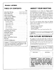
CONGRATULATIONS on your purchase of a Sears GT/18
Twin Garden Tractor. It has been designed, engineered and
manufactured to give you dependability and performance.
Should you experience any problem you cannot easily remedy,
please contact your nearest Sears, Roebuck and Co. or Simpsons Sears Limited store. They have competent, well-trained
technicians and the proper tools and parts to service or repair
this unit.
another free manual from www.searstractormanuals.com
Please read and retain this manual. The instructions will enable
you to assemble, operate and maintain your Tractor properly.
"Always observe the "RULES FOR SAFE OPERATION" ,
YOUR NEW GT /18 TWIN
GARDEN TRACTOR
FEATURES ...
' IV , .
,{
OPPOSED-PISTON, FOUR CYCLE, TWIN-CYLINDER 18
H.P. ENGINE--to run smoothly and quietly with plenty of
power to take on a variety of yard, gardening or snow removal
tasks.
SAFETY INTERLOCK SYSTEM--allows engine to start only
when tractor Clutch-Brake Pedal is depressed and Attachment
Clutch Pedal is in "OF F" position.
ALL-GEAR TRANSMISSION--six speeds forward, two reverse
speeds--to let you select the proper match for the terrain and
the job. Auto-type differential helps guard against turf scuffing.
SERVICE HOUR METER--Iets you know at a glance, when
maintenance is due.
CONTROL PANEL--with Throttle, Choke, Light Switch, Ignition Switch, Service Hour Meter and Electric Lift Switch for
Three Point Hitch conveniently grouped for ease of use.
GARDENS
.....;c . -- ~--._
~l=-
---- ~
. '
NOW REMOVAL
ATTACHMENT VERSA TI LlTY--handles a large variety of
Sears Yard and Garden Tractor Attachments including.
42 AND 48 INCH MOWERS with three "high-lift" blades
to lift grass up for level cuts.
LInER WHISK LAWN SWEEPER is more efficient than
conventional lawn sweepers because of its wheel-less design;
only the rotary brush touches the ground .
SELF POWERED ROTO-TILLER prepares soil for new
lawns and gardens with a 30 to 38 inch wide tilling path.
OTHER SOIL TILLAGE ATTACHMENTS including Plow,
Disc Harrow, Drag Harrow and Cultivator.
CHEVRON TI RES for added traction in loose soil, gravel
or snow.
SNOW BLOWE R handles wet, heavy or powdery snow with
ease .
TABLE OF CONTENTS
WARRANTY
RULES FOR SAFE OPERATION
1
1
ASSEMBLY INSTRUCTIONS
.2
OPERATION INSTRUCTIONS
.4
MAINTENANCE INSTHUCTIONS .
.6
TROUBLE SHOOTING
REPAIR PARTS.
11
12
FULL ONE YEAR WARRANTY
ON ELECTRIC START GARDEN TRACTOR
For one year from the date of purchac~, \iJhcr~ this Garden Tractor is used for personal household purposes, Sears
will repair any defect in material or workmanship in this Garden Tractor, except the battery, at no charge.
another free manual from www.searstractormanuals.com
If this Garden Tractor is used for commercial or rental' purposes, this warranty applies for only 30 days from the
date of purchase.
e
FULL SO-DAY WAR RANTY ON BATTERY
For 90 days from the date ot purchase, if any battery included with the Garden Tractor proves defective in mat·
erial or workmanship and will not hold a charge, Sears will replace the battery, at no charge.
LIMITED WARRANTY ON BATTERY
From the 91 st day until one year from the date of purchase, if any battery included with the Garden Tractor
proves defective in material or workmanship and will not hold a charge, Sears will replace the battery, charging
1 /12th of the price of the new battery for each full month from the date of purchase,
Warranty service is available at your home, at no charge, by simply contacting the nearest Sears store or Service
Center throughout the United States.
This warranty gives you specific legal rights, and you may also have other rights which vary from state to state.
Sears, Roebuck and Co.
Sears Tower
BSC 41-3
Ch icago, I L 60684
RULES FOR SAFE OPERATION
1. Know the controls and how to stop quickly. READ THE
OWNER'S MANUAL.
2. Do not allow chrldren to operate the vehicle. Do not allow
adults to operate it without proper instruction.
3. Do not carry passengers. Keep children and pets a safe distance away.
4. Clear the work area of objects which might be picked up
and thrown.
5. Disengage all attachment clutches and shift into neutral before attempting to start the engine.
6. Disengage power to attachments and stop the engine be·
fore leaving the operator's position.
7. Disengage power to attachments and stop the engine before
making any repairs or adjustments.
8. Disengage power to attachments when transporting or not
rn use.
9. Take all possible precautions when leaving the vehicle un·
attended, such as disengaging the power·take-off, lowering
the attachments, Shlftlllg Into neutral, setting the parking
brake, stopping the engine, and removing the key.
10. Do not stop or start suddenly when gOing uphill or downhrll. Mow up and down the face of slopes (not greater than
15 0 ); never across the face.
11. Reduce speed on slopes and make turns gradually to pre·
vent tipping nr loss of control. Exercise extreme caution
when changing direction on slopes.
12. Stay alert for holes In the terrain and other hidden hazards.
13. Use care when pulling loads or uSing heavy equipment.
a. Use only approved drawbar hitch points.
b. Limit loads to those you can safely control.
c. Do not turn sharply. Use care when backing.
d. Use counterweights or wheel weights when suggested in
this owner's manual
14. Watch out fOI traffic when crossrng or near roadways.
15. When using any attachments, never direct discharge of
material toward bystanders nor allow anyone near the vehicle while in operation.
16. Handle gasoline with care - it is highly flammable.
a. Use approved gasoline containers.
b, Never remove the cap of the fuel tank or add gasoline to
a running or hot engine, or fill the fuel tank indoors.
Wipe up spilled gasoline.
c. Open doors if the engine is run in the garage - exhaust
fumes are dangerous. Do not run the engine indoors.
17. Keep the vehicle and attachments in good operating condition, and keep safety devices in place.
18. Keep all nuts, bolts and screws tight to be sure the equipment is in safe working condition.
19. Never store the equipment with gasoline in the tank inside
a building where fumes may reach an open flame or spark.
Allow the engine to cool before storing in any enclosure.
20. To reduce fire hazard, keep the engine free of grass, leaves
or e xcessi ve grease.
21. The vehicle and attachments should be stopped and inspected for damage after striking a foreign object, and the damage should be repaired befofe'!iestarting and operating the
equipment.
22. Do not change the engin yovernor settings or overspeed
the engine.
23. When using the vehicle w; ,IIOWE proceed as follows:
a. Mow only in daylig~, Ir if! 9 ou artificial light.
b. Never make a cuttir- ,ight ~AU$tment while the engine
is running if the
'ratormuSt dismount to do so,
c. Shut the engine oh ;,helY.'-emcWf"-9 the grass catcher or
unclogging chute. "
.
:~''\.
d. Check the blade mountin~~pf~~~
proper tightness at
frequent Intervals.
~.·.c -1., "
24. Check the grass catcher bags frequaB,ri,"I,for wear or deterioration. Replace with new bags'. ':'. 5i, safety protection.
c'
t<i'
1~~~·
LOOK FOR THIS SYMBOL TO POINT OUT IMPORTANT
SAFETY PRECAUTIONS. IT MEANS·· An NTION'
BECOME ALERT' YOUR SAFETY IS IN\!
lED.
To assemllie dnti adjust YOllr Tr acto r you will need
one 7/16".9 / 16" and 3 /4" Wrench
VENT CAP
CUT AWA Y VIEW
~
.
·
"7'
NOTE : Right Hand (R .H.l a nd Left Hand (L.H.l are deter·
mined fr o m operator's position.
ASSEMBLY
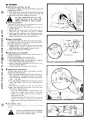
BATTERY
1. Remove
TUBE
2. Filling and charging Battery
0
.
: : .BATTERY
DETAILED
TERY.
CELL
A
---- -M
----------_._-
another free manual from www.searstractormanuals.com
Shipping Wir es . Ba tt er y. Steering Wheel and Bag
of Parts.
(before Installlllg) NOTE : SEE
INSTRUCTIONS PACKAGED WITH BAT ·
WEAR EYE AND FACE SHIELD.
a . Fill Battery with electrolyte to bottoms of tubes in cells
(Fig . 1). NOTE DO NOT OVERFILL. OVERFILLING
WILL RESULT IN DAMAGE TO TRACTOR.
A
WASH HANDS OR CLOTHING IMMEDI·
ATELY IF ACCIDENTALLY IN CONTACT
WITH E LECTROL YTE.
b. Check level of electrolyte after 30 minutes. Add addi·
tional electrolyte if necessary. NOTE: Tighten Vent
Caps securely,
c. Charge Battery at a rate not exceeding three amperes
for about two and one half hours .
HOOD
LATCH
FIGURE 2
A
DO NOT SMOKE . FUMES FROM CHARG·
~ ED ELECTROLYTE ARE EXPLOSIVE.
d. Neutralize excess electrolyte for disposal by adding it to
four inches of water in a five gallon plastic container.
Stir with a wooden or plastic paddle while adding bak·
ing soda until the addition of more soda causes no more
foaming.
3. Install
Battery using :
6;:::::::======9
~
-. ~@~,-===~~
Battery Clamp, two Wing Nuts, two Battery Bolts,
four Flat Washers, two Hex Bolts and two Hex Nuts found
in Bag of Parts.
a. Push down and slightly spread rear sides of Hood to re o
lease Hood Latches . Lift Hood from rear sides (Fig. 2).
b . Remove tape from Plastic Tray. Position Plastic Tray so
that drain hole in Tray is over round hole of Battery
Support.
C. Piace Battery in Plastic Tray (Battery Terminals to front
of Tractor) (Fig. 3).
d . Hook the curved shank Battery Bolt into slot on th e
left side of Battery Support (Fig. 3). Fasten Battery
Clamp to Battery Bolt with a Flat Washer and Wing
Nut.
e. Hook the straight shank Battery Bolt into slot in R. H.
Hood Latch and fas te n Battery Clamp with a Flat
Washer and Wing Nut (Fig. 4). T ighten Wing Nuts secure ·
Iy.
f. Place a Flat Wash e r over th e e nd of a Hex Bolt. Secure
RED Battery Cabl e to Positive (+) Battery Te rminal with
a Hex Bolt (Washer) and Hex Nut (Fig. 5). Tighten Nut
securely. Place Boot over Ter minal.
A
·2·
POSITIVE TERMINAL MUST BE CON ·
NECTED FIRST TO PREVENT SPARKS
FROM ACCIDENTAL GROUNDING.
g. fJlace remaining Flat Wa sh er over the end of the remain ·
ing Hex Bolt. Secure BLACK Ground Cable to Nega tiv e
(- ) Battery Terminal with Hex Bolt (Washer) and Hex
Nut (Fig. 5). Tighten Nut securely.
4. Install
Steering Wheel using:
o c
another free manual from www.searstractormanuals.com
Flat Washer, Lockwasher and Hex Bolt assembled on end
of Steering Shaft.
Woodruff Key, and Steering Wheel Insert found in Bag of
Parts.
a. Remove Hex Bolt, Lockwasher and Flat Washer from
Steering Shaft (Fig. 6) .
b. Insert Woodruff Key in Keyway of Steering Shaft and
slide Steering Wheel over Shaft and Key. NOTE: BE
SURE WOODRUFF KEY IS SECURE IN STEERING
SHAFT.
c. Fasten with Flat Washer, Lockwasher and Hex Bolt (Fig.
6). Tighten securely.
d. Press Steering Wheel Insert :11 place.
THIS TRACTOR IS EQUIPPED
WITH
SAFETY
SWITCHES
TO
PREVENT
STARTING OF THE TRACTOR ENGINE
WHILE THE
ATTACHMENT CLUTCH
PEDAL IS IN THE "ON" POSITION (FIG.
10) AND THE CLUTCH BRAKE PEDAL
IS IN DRIVE POSITION (FIG . 12).
IMMEDIATELY
REPLACE SWITCHES
THAT ARE NOT IN PROPER WORKING
ORDER. DO NOT ATTEMPT TO DEFEAT
THE PURPOSE OF THESE SWITCHES.
INITIAL ADJUSTMENTS
1. Reduce Tire preSS lHI! to 12 pounds in front and l ea r Tir es .
(Tir es wel(! ovt' llnflatl'<i fOI shippinq purposes).
2. Seat
position may be adjusted forward or backward by
loosening Nut in Seat Plate (Fig. 7). NOTE: WHEN RE·
TIGHTENING NUT AFTER ADJUSTMENT, MAKE SURE
SEAT PLATE HAS NOT TWISTED OUT OF ALIGNMENT WITH SEAT SPRING.
INITIAL SERVICE
NOTE BE CAREFUL NOT TO ALLOW DIRT TO ENTfR
THE ENGINE WHEN CHECKING OR ADDING OIL OR
FUEL.
FIGURE 8
1.Check Engine Oil Level with Tractor on level qround .
Wipe dipst;ck (Fig . 8) cl ean , push it in t ight for a few sec ·
onds, remove and read 011 Level. If nccessilry , add Oil unt il
"FULL" mark is reached . In summer use S.A .E. 30 (SC,
SD or SE) Oil. In winter (below 32°F.) use S.A.E . lOW30
(SC , SD 01 SE) or 10W40 (SC, SD or SE) . In extr eme cold
(below OOF .) use S.A.E . 5W20 (SC, SD or SE) . NOTE
DO NOT OVERFILL
2. Fill
Fuel T;lI1k (FHj . 7) wot h III'S)) It'qu l;1I ql ;ull' Il'dd ·III'I- 01
leaded qasolllw C.lpa clty IS 3
1 4 (jali ullS NOTE DO
NOT SWITCH FROM LEADED TO LEA D FR EE GASO
LINE
FILL TO BOTTOM OF GAS TANK FILLER NECK. DO NOT OVERFILl. WIPE
OFF ANY SPILLED OIL OR FUEL.
·3 ·
OPERATION
STARTING 1 HE ENGINE
1. Pla ce Parking Br a ke Le ve r In lo c ked
2. Place Attachment Clutch
3. Pla ce
PO Slt, o n (Fig . 9 1.
Pedal in "OFF" position (Fig. 10)
Gear Shift Lever in neutral "N" POSit ion (Fig. 11) .
4.Move Range Shift Lever
to
"N" neutral positio n (Fig . 11).
5.Push Clutch · Bra ke Pedal into bra ke POSiti on IF,g
another free manual from www.searstractormanuals.com
6. Move
FIGURE 9
7. Pull
12) .
Throttle Control Lever to middle pos it io n (F ig. 13) .
Choke out (F ig. 13).
S. Turn
Ignition Key to "START" position until Engine starts
(Fig . 13). Release key into "ON" position.
NOTE : DO NOT RUN STARTER CONTINUOUSLY FOR
MORE THAN THIRTY SECONDS AT A TIME. If engine
does not start after several attempts, move Throttle Control
Lever to "FAST" posit ion, wait a few minutes, and try
again.
NOTE: The Electric Lift Switch (F ig. 13) raises or lowers
an attachment when used with a Three Point Hitch (optional
equipment).
IGURE 10
WARMING UP THE ENGINE
Move Throttle Control Lever to slow position . Push Choke
in as engine warms. NOTE: ALLOW ENGINE TO WARM
UP FOR A FEW MINUTES BEFORE OPERATING .
When restarting a warm engine, move Throttle Control Lever
to middle position, Choke may not have to be used .
A
ALWAYS WEAR SUBSTANTIAL FOOT·
WEAR AND AVOID LOOSE
FITTING
CLOTHING THAT COULD GET CAUGHT
IN MOVING PARTS .
LEARN TO START, STOP AND REVERSE
YOUR TRACTOR IN A LARGE, OPEN
SPACE .
. 4 · . . . . . . . . . . . . . . . . . . . . . . . . . . . . . .. . .
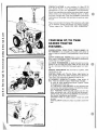
TRACTOR OPERATION
1. With
engine running and warm, place Throttle Lev,'r
middle pOSition.
TRACTOR OPERATION ON HILLS
Ifl
1.ChllD'C (lIll'
down 11111s
2. Push Clutch·Brake Pedal down to brake position
A
3. Move Gear Shift Lever to "2ND" and Range Shift Lever to
"LOW'"
4. Unlock
Parking Brake.
5. Release
Clutch· Brake
movement.
ic)Wt,q
qt'.HS
BEFORE starting up or
DO NOT DRIVE UP OR DOWN HILLS
WITH SLOPES GREATER THAN 15°, AND
DO NOT DRIVE ACROSS ANY SLOPE.
2.Avold shifting or stoPPing on hills
Pedal
a
If slOWing IS Ilt'CeSsdry, move Throttle Control to middle
POSition
b. If stoPPlIlq IS IH'Cl'SSdIY, push ClutchBlak,' Pedal qUick·
Iy to bl ake POSit Ion to pi event lolling
c. Lock Parking Brake and shift to lowest speed range.
SLOW L Y to start forward
6. If
another free manual from www.searstractormanuals.com
tilt'
elf
ground travel is too slow move Throttle Lever to fast posi·
tion or press Clutch-Brake pedal and shift to a different
gear. NOTE: ALWAYS SELECT A GROUND TRAVEL
SPEED THAT WILL SUIT THE TERRAIN AND THE
ATTACHMENT BEING USED.
d. Partially leleasp Clutch Bldke P"ddl (until forward move·
ment begrns.
e. Unlock Parking Brake.
f. Completely lelease Clutch Blake Pedal
BRING TRACTOR TO COMPLETE STOP
BEFORE SHIFTING GEARS.
3.Make all turns gradually
NEVER PLACE YOUR HANDS OR FEET
IN OR UNDER ANY POWERED ATTACHMENT OR NEAR ANY MOVING PART
WHILE TRACTOR OR ANY POWERED
ATTACHMENT IS RUNNING.
STARTING YOUR TRACTOR
WITH A lOW BATTERY
STOPPING YOUR TRACTOR
1. Reduce Throttle
If your BafU'ry IS too low It) qart th .. enQlne, It should be
recharged. If "Jumper Cables" are u'>ed for emergency starting
follow this procedure NOTE YOUR TRACTOR IS EOUIP·
PED WITH A 12 VOLT NEGATIVE: GROUNDED SYSTEM.
THE OTHER VEHICLE MUST ALSO BE A 12 VOLT
NEGATIVE GROUNDEr' SYSTEM
Lever to "SLOW" position.
2. Push Clutch·Brake Pedal into Brake position.
3. Place Attachment Clutch Pedal in "OFF" position and low·
er attachment to the ground.
4. Move Gear Shift
5. Place Parking Brake in
6.
LEAD ACID BATTERIES GENERATE EX·
r'JSIVE GAS~ES.KEEP Srr,RKS,FLAME.
AND SMOK!NG MATERIALS AWAYFROM
BATTERIE;;.
ALWAYS SHIELD EYES
AflOUNu of\TTERI>.
Lever to neutral "N".
"LOCK" position.
Release Clutch· Brake Pedal.
A
7. Turn
1. Connect
termlllais
MAKE SURE PARKING BRAKE WILL
HOLD TRACTOR SECURE.
0\ "del:
batt!:1 y
C,Ii)["
(l,'i' lliq Cdlt
to the P()SIT IVE (t)
:''it II) ',hOI t iHJalnst
Chilc,c,IS)
Ignition Key to "OFF" position.
A
eacll "[Id (,I thl: RED
2.ColHwct
(J/II:
Illd
(-) tfi[
:cii'
",
of tl1I: HLALK cahl" II) III!' NlGATIVE
,/JUl) tJellt"1 I
3.ConrWCI tlw oth'" "I\d of till: cilblf! to FNCliNE BLOCK
01 (¥Jod CHI\SSI:J (JRUl)NU on fldUOI (aw"i from Gas
Tank or Battl:ty)
REMOVE KEY WHEN LEAVING TRAC·
TOR TO PREVENT UNAUTHORIZED USE.
4.D,scorHH'ct cdblf",
TRANSPORTING YOUR TRACTOR
Enqll1l: BII)r:K
h
c
NI'QdlIVI' Jlllnilidl f)f
- 5-
IJI
cha',)I',
"C)()U[)" halTl'IY
P(J(,lfl\)I't;'frllU:dl'J
A
For pushing or towing your tractor, place Gear Shift Level
3nei Range Shift Lever in "N" (Neutral) position (Fig 11)
NOTE DO NOT TOW Your TRACTOR FASTER THAN
SIX MILES PER HOUR.
H1 ti"J!'r',f' ()t(jf.!
a
DO NOT USE YOUR IRACTOR BAT·
TERY TO START OTHER VEHICLES.
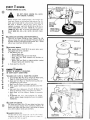
MAINTENANCE
....----::=:=:-SI XT Y HOUR :..---==---..--.. : : :~ i li l
HAND
I';,
00
J/ /
'
x~.:>->-----HOURHAND
~~~~----~~-SYSTEM
another free manual from www.searstractormanuals.com
INDICATOR
To keep your tractor runnlllg better. longer; perform necessary
service uSing the follOWing Maintenance Schedul~ and the SerVice Hour Meter IF,q 14 ) on the traclClr dash.
The Service Hour ' Meter records the number of hours of
traclOr operation . Read th e Hour Hand on the outer dial ; each
mark Indicating one hour of ope ration . Read the Sixty Hour
Hand on the Inner dial, each mark indicating sixty hours of
operation . The System Indicator moves visibly when the
Ignition Key is in the "ON" position, indicating the system
operational .
DISCONNECT SPARK PLUG WIRES TO
PREVENT ACCIDENTAL STARTING BE·
FORE MAKING ANY INSPECTION, AD·
JUSTMENT (EXCEPT CARBURETOR' OR
REPAIR .
FIRST
~
HOURS:
1.CHECK V·BELTTENSION
A new V-Belt may stretch after the first few hours of opera·
tion. If Clutch·Brake Pedal, in drive position (Fig. 151. is
considerably to the front or rear of the vertical position,
the V-Belt is out of adjustment and must be re ·t ensioned .
a. Secure Clutch -Brake pedal in brake position (relaxing
V-Belt tension) by tieing to front axle.
b. Hold Nut on inside of Flat Idler and loosen Flat Idler
Bolt.
c. Move Flat Idler in frame slot 1/4 inch down (to tighten),
up (to loosen) V-Belt tension. Tighten Bolt .
d. Release Clutch -Brake Pedal. It should return to approximately vertical position .
FIGUR E 15
A
CHECK TO MAKE SURE TRACTOR DOES
NOT START WITHOUT FULLY DEPRES·
SING CLUTCH·BRAKE PEDAl.
NOTE: FOR LONGER V -BELT LIFE, ALWAYS KEEP
BELT TENSIONED
PROPERLY. START TRACTOR
MOVEMENT WITH THROTTLE CONTROL IN MID·
OLE POSITION, AND ALWAYS REPLACE WITH SEARS
V·BELTS.
2.CHANGE ENGINE OIL
Changing Oil after the first two hours will help eliminate
break-in residue which might be damaging to your Engine.
FIGUR E 16
Note : Be careful not to allow dirt to enter the Engine
when changing oil.
a. Drain Oil with Engine warm. Unscrew Oil Drain Cap
(Fig. 16) and catch Oil in a suitable container. Replace
Cap.
b. Refill Engine Oil (Fig. 17). In summer use S.A.E . 30
(SC, SO or SE) Oil. In winter (below 32 0 F.) use S.A.E.
10W30 (SC, SO or SE) or lOW40 (SC, SO or SE). In extreme cold (below OOF.) use S.A.E. 5W20 (SC, SO. or
SE) . Capacity is 3 - 112 pints . NOTE: DO NOT OVE R·
FILL.
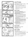
FREQUENTLY:
A-"'VENT CAP
CUT - AWAY VIEW
1
1
i
r-lr
.
:~
:. !.~
~l:
BATTERY
TUBE
1. CHECK BATTERY
a. Electrolyte solution level in each Battery Cell should be
even with bottoms of tubes in cells (Fig . 18). Add distilled wat er if necessary . NOTE : DO NOT OVERFILL
b. Keep Battery and Terminals clean. Refer to page 10.
c. Keep Battery bolts tight.
d. Keep Vent Ca ps tight and small Vent holes in caps
o pen.
e. Recharge SLOWLY at 3 amperes if specific gravity of
electro lyte falls below 1.225.
2.CHECK TIRE PRESSURE
Tir e pressure in front and rear Tires should be 12 pounds.
1
3_
CLEAN AIR SCREEN
--1J '
"
FIGURE 18 : :::-_-_- ; -_-_-_-_-~ _' j
AI! Screen and Guard (F ig 21 ) must be kept free of d irt
. ._ _ _ _ _ _ _ _ _ _ _ _ _ _ _ _ _ _ _ _ _ _• . 6and chaff t o prevent Engi ne damage from overheating.
:, 1
\1.
n
BCAElTlTERY
EVERY
0 HOURS:
1. CHECK ENGINE OIL LEVEL
STEERING GEAR
====;>~= SECTOR AND
ARM GREASE
FITTING
another free manual from www.searstractormanuals.com
DO NOT CHECK ENGINE OIL LEVEL
WITH ENGINE RUNNING .
Several minutes after stopping Engtn e , ch ec k Engine ad
Level with Tractor on level ground. Wipe dip stick (Fig. 17)
clean, push it down ticj1t for a few seconds, remove and read
Oil Level. If necessary, add Oil untit "FULL" mark is
reached. In summer use S.A.E. 30 (SC, SD or SE) Oil. In
winter (below 32 0 F.) use S.A .E. 10W30 (SC, SD or SE) or
lOW40 (SC, SD or SE). In extreme cold (below OOF.) use
S.A.E . 5W20 (SC, SO or SE). NOTE: DO NOT OVER ·
FILL.
FRONT AXLE
PIVOT
STEERING
BElLCRANK
GREASE
FITTING
FRONT SPINDLE
GREASE FITTING
(LEFT & RIGHT)
FIGURE 19
2. LUBRICATE STEERING AND
FRONTWHEELS
There are six Grease Fittings on your Tractor (Fig. 19).
Using a Grease Gun, give each Grease Fitting two shots of
Extreme Pressure Lubricating Grease Amdex No . 1 (Available at your loeal Sears Service Center).
3.01L PIVOT POINTS
Place several drops of SAE 30 Oil at points where parts
move against each other, especially:
a . Idler Bearing (Fig . 15)
-- Remove Plastic Cap .
-- Remove Retainer Spring from Idler Shaft.
-- Move Idler and Shaft outward and lubricate exposed Shaft.
-- Return Idler and Shaft to original position, replace
Retainer Sp'ring and reposition Cap.
~----- WING NUT
AIR FILTER
COVER
FOAM
PRE-CLEANER
~_-PAPER
AIR FILTER
ELEMENT
b. Front Axle Pivot (Fig. 19)
EVERY~HOURS:
(EVERY 15 HOURS IF OPERATING
IN VERY DUSTY CONDITIONS)
1.CLEAN AIR FILTER & FOAM PRE-CLEANER
a , Unscrew Wing Nut (Fig. 20) to remove Air Filter Cover,
Paper Air Filter Element and Foam Pre-Cleaner.
b . Clean dust from Paper Air Filter Element by gently tapping Element on a flat surface .
c . Wash Foam Pre ·Cleaner in detergent and water .
d. Rinse, squeeze (rather than twist) and allow to dry thoroughly .
e. Coat with three tabl espoons of S.A.E. 30 Engine Oit,
knead to distribute evenly, and squeeze out excess .
f. Check Papel Air Filter Element. Re place if excessively
dirty.
g. Re -Assemble Air Fi l ~~r and re-position on Tractor.
NOTE NEVER RUN ENGINE WITH AIR CL[ANER
REMOVED.
2.CLEAN AIR SCREEN
Air Screen and Guard (Fig. 21) must allow free-flow of air
to prevent Engine damage from overheating. Remove Air
Screen and Guard and clean with a wi re brush to remove
dirt, chaff, stubborn dried gum and fibers .
3.CHANGE ENGINE OIL
The bes t time to chanye Engi ne ad IS at the en d o f a da y~
operation wh en all dirt an d fOI e lgn materi a l IS suspend,'"
in th e ho t Oil Ref e r to page 6 .
F IGU R E 21
- 7 - . .- - - - - - - - - - - -- - - - - - - - -. .
EVERY
~@ HOURS:
1. CLEAN
another free manual from www.searstractormanuals.com
ENGINE COOLING FINS
Remove any du st, dirt 01 01 1 from EnlJlne Coo ling F ins
( Fig 22) t o iJr event Engine damage fr om overheating .
2.CHECK TRANSAXLE OIL LEVEL
a. Block up Rear A x le secur ely or use a T ra ctor Jack.
Rem ove left r ear wheel by removing E·Ring.
h . Remove F,llel Plug (F ig 23) from Tran saxl e. all Level
should be ev en with Fill er Plug th rea ds. Add S.A.E. 30
Mot o r Oi I I f necessary .
c. Chec k Pr e:sure Rel ie f Valve located on R.H. side near
top (Fig. 26). It sho uld sprrng completely closed when
pull ed out by han e!.
d . Reposition wheel. Secure with E·Ring.
EVERvTIOOOO HOURS:
1. CLEAN SPARK
TRANSAXLE
FILLER PLUG
PLUGS AND RESET GAP
Wire brush carbon deposits from Spark Plug Electrodes and
reset gap at .025 inch. (Fig. 25). Replace Spark Plugs if
they show signs of foulino or electrode erosion.
2.CHECK BREAKER POINTS
Replace Points if they are pitted or burned.
a. Remove Air Intake Hose that connects to Blower Hous·
ing (Fig . 24) . This provides an access to view Timing
Mark .
b. Remove Spark Plugs and Belt Guard and turn Engine
Pulley (Fig. 15) clockwise by hand until 21 0 BTC mark
on gear cover aligns with mark on flywheel. Turn anoth·
er 1/4 turn to ensure points are fully open.
c. Remove Breaker Bo)< Cover (F ig . 22) by loosening Screw
and lift off to remove.
d . Replace Points. if necessary.
e. Using an Allen Wrench, adjust Set Screw for .021 inch
between Points. Measure Point Gap with a Flat Feeler
Gauge. NOTE : MAKE SURE FEELER GAUGE IS
CLEAN AND FREE OF GREASE, OIL, OR DIRT. No
other adjustment or alignment is necessary. Setting point
gap accurately adju sts Engine Timing.
f . Replace Break er Box Cover, Spark Plugs and Cables
and Air Intak e Hose .
3.LUBRICATE BALL JOINTS
a. Move Rubber Boot s to expo se Ball Joints on lie Hods
and Steering Link (Fig. 28).
b . Coat Ball Joints with Silicone Spray Lubricant.
c. Reposition Rubber Boots.
EVERV~UJ HOURS:
1. REPLACE
PAPER AI R FI L TER ELEMENT
Refer to paQe 7.
FIGURE 25
2.REPLACE BREAKER POINTS
Refer to step 2, above.
EVERY LDffiOO HOURS:
CHANGE TRANSAXLE 01 L
a. Bl oc k up Rear Axle securely or use a Tractor Jack. Remove
Left Rea r Wh ee l by removing E·Ring.
b. DI ain T r ansax Ie Oil by rernov ing Drain Plug (F ig . 26) and
catchIng a ll In sUi tabl e con tarner. Replace Drain PluQ.
c Refill Transaxle with S.A.E. 30 (SC, SO or SE) Motor Oil.
l.H . SIDE
.._________ii~;.___________.. .
Capac ity IS 5 qu,v t s. Pressure Reli ef Valve (R.H. side of
T ran saxl e , r iq. 26, I:l se t) may be held open to allow Trans·
axl e to fill mOle qu ickly.
C1 Ch ec k Pres sule Reli ef Val ve . It should spring co:T1pletely
[ IUSI'll w ht'n pull ed a li t iJy hand and re leased .
8. (' R,'po s,t l()ll \yht't" S"'Cll't' w i th E· R,ng .
AS NEEDED:
1. REPLACE
IN-LINE FUEL FILTER
If fuel filter is clogged, obstructing fuel flow to carburetor,
replacement is required.
a. With Engine cool, remove and plug Fuel Line Sections
as removed from both ends of Fuel Filter (Fig. 27).
b. Place new Fuel Filter in position in Fuel Line.
another free manual from www.searstractormanuals.com
A
BE SURE THERE ARE NO FUEL LINE
LEAKS AND THAT FUEL LINE IS IN
PROPER POSITION IN HOSE CLAMPS.
2.TOE·IN ADJUSTMENT
If any parts In Front Axle or Steering Mechanism are being
replaced, Tie Rod adjustment IS required.
a. Loosen Jam Nuts (Fig. 28) at each end of Tie Rod Ad
justment Sleeves.
b. Adjust both Tie Rods so that Tie Rod JOints measure
from 10 to 10
1/8 mches from center to center.
c. Tighten Jam Nuts, making sure Tie Rod Joints are par·
allel (1800 ) to each other. This adjustment secures
proper Front Wheel Toe·in and steering operation.
3.BRAKE ADJUSTMENT
If Clutch·Brake Pedal (Fig. 29) has more than approximate
Iy 4 inches of travel from vertical to full brake position
then brake adjustment is necessary.
a. Loosen Jam Nut (Fig. 29) in order to turn turnbuckle
clockwise (from in front of tractor) one turn at a time
until Clutch·Brake Pedal regains 4 inches of travel.
b. Tighten Jam Nut against Turnbuckle.
4.PARKING BRAKE ADJUSTMENT
If Parking Brake will not hold tractor, Parking Brake ad·
justment is necessary.
a. Loosen Parking Brake Hex Nuts (Fig. 29).
b. Place Parking Brake Lever in locked position.
c. Hold Clutch·8rake Pedal in brake position and tighten
first Hex Nut finger tight against Bushing.
d. Release Clutch·Brake Pedal and turn first Hex Nut two
. turns more agamst Bushing.
e. Tighten second Hex Nut against first Hex Nut.
FIGURE 28
5.CARBURETOR ADJUSTMENT
If Engine lacks power or does not idle properly, the Car·
buretor may need adjustment.
a. Main Fuel (High Speed) Screw (Fig. 30) snould not reo
quire adjustment. If resetting is necessary, turn clock·
wise, closing finger tight ON L Y, then turn counterclock·
wise 1 . 1/2 turns.
b. Turn Idle Adjusting Needle (Fig. 30) clockwise, closing
finger tight ON L Y, and then turn counterclockwl::.e
one turn.
c. Start Engine and allow to warm for five minutes.
d. Make final adjustments with Engine running and Gear
Shift Lever in Neutral position .
.. Turn Idle Adjusting Needle counterclockwise until
Engine runs "rough" then clockwise until Engine
begins to miss. Return Screw to a point midway between these extremes.
Throttle Stop Screw (Fig. 30) should not require ad·
justment. If resetting IS necessary, set to obtain the
slowest engine speed that will allow smooth acceleration.
G. RE·TENSION
V·BEL T
It may be occasionally IleCeSSdlY to Ie tellslOIl Vhl!lt (SI'(,
page 6).
CHFCK TO MAKE SURE TRACTOR DOES
NOT START WITHOUT FULL Y DEPRES
SING CLUTCH-BRAKE PEDAL.
STOP
SCRf'W
7. V·BEL T
REPLACEMENT
a. Remove Belt from Clutch Idler by depressing Clutch·
Brake Pedal (Fig. 31).
b. Remove Belt Guide from Engine Pulley.
c. Remove Rear Belt Guide Assembly from Transmission
Pulley.
d. Loosen Flat Idler Assembly on R.H. side of Tractor
Frame.
e. Remove Belt from Engine Pulley, between Belt Guide
Finger (note position of Belt) and Flat Idler, and Transmission Pulley.
f. Place new Belt around Transmission Pulley. Then place
Belt between Belt Guide Finger and Flat Idler and then
around Engine Pulley.
g. Depress Clutch-Brake Pedal and slip Belt over the top of
the Clutch Idler.
h. Replace Engine Pulley Belt Guide and Transmission Pulley Belt Guide. Tighten Flat Idler Assembly. NOTE:
Make sure Belt Guide Finger on Flat Idler is parallel
with slot in Tractor Frame.
i. Check Belt tension, page 6.
TRACTOR
FRAME
"""'~.~
CLUTCH·
BRAKE
--------·PEDAL
TRANSMISSION
PULLEY
another free manual from www.searstractormanuals.com
FIGURE 31
WEAR
WASHER
NUT WASHER
\
::T~A~~~
FIGURE 32
PIN
8.CLEAN BATTERY AND TERMINALS
Corroslo'l and dirt on the Battery dnd Terminals cause
the Batter y to "leak" power and hinders the operation of
the charger
a Remove the Battery from the Tractor and wash with
four tablespoons of bakmg soda to one gallon of water.
NOTE BE CAREFUL NOT TO GET THE SODA
SOLUTION INTO THE CELLS. Rinse the Battery with
plain water, dry and reinstall on Tractor.
b. Clean terminals With a wire brush until bright. Re·
place Batter y Cables. Coat termmal connections with
Vasoline.
~
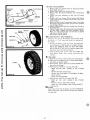
9. TIRE
FIGURE 33
CARE
d. Maintain tire pressure m front and rear tires of 12 pounds.
b. Keep tires free of gasoline, oil, or insect control chemi·
cals which can destroy rubber.
c. Avoid stumps, stones, deep ruts and other hazards that
may cause tire damage.
d. Removing front wheel for tire repair (Fig. 32).
-- Block up front axle
securely or use a Tractor
Jack.
Remove Hex Bolt and DU5t Cap .
.. Remove Nut, Wear Washer, Pin and Washer to allow
wheel removal.
.. Repair tire and reassemble.
e. RemOVing rear wheel for tire repair (Fig. 33).
.. Block up
rear
axle
securely or use a Tractor
Jack.
Remove E·Ring to allow wheel removal.
.. Repair tire and reassemble. Snap E·Ring securely in
axle groove .
10 • FINISH
Keep tractor finish free of gasoline, oil, insect chemicals or
battery electrolyte. Protect painted surfaces with Automo·
tive type wax .
. 10
TROUBLE SHOOTING
POSSIBLE CAUSE
POSSIBLE REMEDY
WILL NOT START
Clutch-Brake Pedal In drive position
Attachment Clutch Pedal In "ON" ~,)Sltlon
No gasoline In Fuel Tank, clo']ged Fuel Filter
or Fuel Line
Blown Fuse
Dead Battery
Press Pedal Into brake POSition
Move Pedal to "OFF" po~itlOn
Fill Tank with Gasoline. Check Fuel Line, Fuel Filter
and Carburetor (clean If necessary)
Check for fault and replace Fuse
Recharge or replace Battery
another free manual from www.searstractormanuals.com
HARD TO START
Choked Improperly, flooded Engine
Clogged Fuel Filter
Clogged Fuel Tank
Dirty Air Cleaner
Spark Plugs dirty or improper gap
Defective Battery
Defective Ignition or loose wiring
Water in gasoline or old fuel
Improper Carburetor adjustment
Push Choke In, place Throttle Control In middle position and run starter several times to clear out gas
Remove and replace
Remove and clean
Remove and clean
Clean, adjust gap or replace
Recharge or replace
Check the wiring and Spark Plugs
Drain Fuel Tank and Carburetor, use fresh fuel and
clean Spark Plugs
Make necessary adjustments
ENGINE MISSES OR LACKS POWER
Engine overload
Clogged Fuel Filter
Clogged Fuel Tank
Partially plugged Air Cleaner
Improper Carburetor adjustment
Dirty Air Screen
Low oil level or dirty oil
Spark Plugs dirty, improper gap or wrong type
FaUlty ignitIOn
Poor compression
Oil in gasoline
Shift to a lower gear or reduce load
Remove and replace
Remove and clean
Remove and clean
Make necessary adjustments
Clean Air Screen and Cylinder Fins
Add or change oil
Clean, reset gap or replace
Check Spark Plugs and for loose wires
Major Engine overhaul
Drain and refill Gas Tank and Carburetor
ENGINE OVERHEATS
Dirty Air Screen
Low oil level or dirty oil
Dirty Engine
Partially plugged Mufflers
Partially plugged Air Cleaner
Stale fuel or improper Carburetor adjustment
Clean Air Screen
Add or change oil
Clean Cylinder Fins
Remove and clean Mufflers
Remove and clean
Use fresh fuel and adjust Carburetor
NO LIGHTS
No Headlights or Taillight with Light Switch Knob
pulled out
Check Light Fuse under dash, replace Taillight Bulb
or Sealed Beam Headlights
WON'T CHARGE
Blown Fuse
Defective Battery
Check for fault and replace
Replace
STORAGE
1. ENGINE OIL
Drain (with engine warm) and replace with clean engine oiL
Refer to page 6_
2. FUEL SYSTEM
a_ Drain fuel tank and carburetor by allowing the engine to
run outof gasoline_ NOTE GASOLINE LEFT IN YOUR
ENGINE WI LL LEAVE GUM DEPOSITS CLOGGING
FUEL SYSTEM_
b. Dispose of gasoline If not to be used. NOTE GASOLINE STORED FOR SEVERAL MONTHS LOSES
ITS VOLATILITY (ABILITY TO BURN EFFECT
IVELY)
4.BATTERY
a. Remove battery If tractor IS not used regularly during
winter months. Store in cool, dry place (above 50 0 F).
NOTE DO NOT STORE BATTERY DIRECTLY ON
CEMENT SURFACE.
b. Check electrolyte charge each month and recharge if
below 1.225 specific gravity. NOTE BATTE R I ES NOT
IN USE FOR SEVE RAL MONTHS AND NOT KEPT
FULLY CHARGED, PRODUCE SULPHUR DEPOSITS
ON PLATES WHICH CANNOT BE REMOVED BY
RECHARGING.
5.GENERAL CLEANING
Clean engine. battery, finish. etc. of all foreign matter.
3.CYLINDER
a. Remove Spark Plugs.
b. Pour one ounce of all thlough spark plug hole into cy
Iinder.
Sears, Roebuck and Co. or Simpsons-Sears Ltd. in Canada rec. Turn ignition key to "START" position for a few
serves the right to make any changes in design or improvements without imposing any obligation to install the same
seconds to distribute oil.
_ 11 _upon its items heretofore manufactured.
d. Replace Spark Plugs.
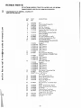
REPAIR PARTS
GT/18 TWIN-GARDEN TRACTOR--MODEL NO. 917.257061
<::>-89
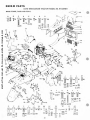
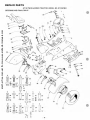
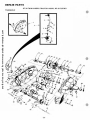
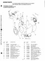
MAIN FRAME, DASH AND GRILL
A
=78
c:S:> 79
1IIl80
e
B
'i
87
D
82
E
1'84 i 85
F
181
H
i tf
G
33
=- 79 c::s;::, 86
-' 98
a:§I)83
'03
~
another free manual from www.searstractormanuals.com
73
. ,ee
v~ ._~ ~'s
w
6/
N
~\.
2'~
22
118
M
L
K
I"OU., 194
---:t
'
,.
..
=98
<::S:J 96
IJ) 97
W
ff
U
'"
a
p
~96
[]J
"91
97 ~86
(II] 93
s
R
T
~, 96
95. (I]) 97
=
~96
98
~96
lIIJ97
(@j109 ~100
u
v
w
x
y
l
AA
BB
n '02 95 V'04 ' ,o5 fj',oltf,o,<Il,lO r
U
~86 ,
, 98
rr::.D 93 ~ 96
[Ii 97
r
~96 ~107 [E] 109
ec
U 111 U 115
112
0-=113
:::~ ~14
[})9 7
~=
78
= 79
CLIl 80
DD
U
11 6
-~
~
- 12 .
EE
,~
=
GG
FF
98
- - 121
98 CIIl1l7
96
97
1
119
[120
~ 86
=91
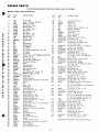
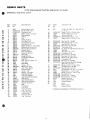
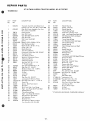
REPAIR PARTS
GT/18 TWIN-GARDEN TRACTOR--MODEL NO. 917.257061
another free manual from www.searstractormanuals.com
I»
fit
MAIN FRAME, DASH AND GRILL
KEY
NO.
PART
NO.
DESCRIPTION
1
2
4
5
6
7
8
9
10
11
12
13
14
15
16
17
18
19
20
21
22
23
24
25
26
27
28
29
30
31
32
33
34
35
36
37
38
39
40
41
42
43
45
46
47
48
49
50
51
52
53
54
55
56
57
58
59
60
61
62
63
64
65
66
67
Grill - Upper
911J
68
Gasket - Exhaust Manifold
878J
69
285J
Decal - 6" Speed
70
Grill Screen - Upper
2794R
71
8768H
Mounting Clip
72
2672R
Grill Screen - Center
73
7937R
Grill - Lower
74
7938R
Grill Side
75
2674R
Grill Screen - L.H.
76
2673R
Grill Screen - R.H.
77
105J
Muffler - Rear
78
104J
Muffler - Front
79
634A901
CI utch Peda I
80
89J
Link
81
Push-On Nut
92J
93J,
Rubber Pedal
82
91J
Pivot Spacer
83
267J
Foot Pedal
84
3366P
Soc. Hd. Cap Screw 5/16 - 18 x 3/4
85
8058R
Grill Cable
86
875J
Grill Brace
87
634A910
Engine, Onan 18 H.P_B48M-GA018/3417A
Sq_ Key 1/4 x 2
9396E
89
8245R
Belt Retainer Finger
91
634A104
Engine Pulley w/Set Screws
92
634A527
Belt Guide Weldment
93
8704H1
Spacer
94
4939M
Retainer Spring
Belt Retainer
9011H
95
634A659
Belt Guard Weldment
96
8238H
Split Spacer
97
50P
Carriage Bolt 3/8 - 16 x 2 - 1/4
98
1545P
Washer 17/32 x 1 x 16 Ga.
99
STD561210 *Cotter Pin 1/8 x 1
634A900
Hood Latch
100
8457R
Support Bumper
102
634A903
Battery Support Bracket (I nco Key 39)
103
7756R
Bearing
104
Cap
8006R
7729R
Cover - R.H.
105
281J
Model Decal
634A902
Lever Weldment
106
634A785
Hanger Weldment R.H_ - Front
107
7944R
Belt Tightener Arm
108
7948R
Return Spring
109
7810H
Locknut 3/8 - 24 UNF
110
634A814
Hanger Weldment - Rear
634A787
Drawbar and Weldnuts
111
634A355
Hanger Weldment - L.H. - Front
112
7931R
Choke Control
113
9900R
Throttle Control (Inc. Key 61,62 & 63)
114
97J
Adaptor Bar
115
9634R
Decal (Shift Pattern)
116
634A888
Chassis Ass'y. (Inc. Key 57 & 58)
117
6468H
Bearing
118
4766H
Bearing
119
634A908
Engine Mount ASs'y.
Grill Spacer
96J
120
9903R
Throttle Wire & Casing
121
8204R
Clamp
8203R
Throttle Control Lever
634A893
Dashboard (Inc. Key No's, 66 and 67)
Battery Support
106J
Clip - Dashboard
1998R
Clip - Dashboard, Center
8571 R
KEY
NO.
- 13-
PART
NO.
DESCRIPTION
107J
Battery Heat Shield
7874R
Hood Seal
8855R
Battery Tray
86J
Cover - L.H.
113J
Bracket - Battery Support - L.H.
98J
Bracket - Rectifier
885J
Decal - Sears Logo
634A907
Hood Ass'y.
8028R
Decal - Instruction
9880R
Decal - Wiring
STD551025 "Washer 9/32 x 5/8 x 16 Ga.
STD551125 "Lockwasher 1/4
STD541025 "Hex Nut 1/4 - 20 UNC
5501P
Phillips Pan Hd. Thd. Self Tap.
10 - 24 x 3/8 Type T
STD522515 "Hex Bolt 1/4 - 20 xl - 1/2 Grade 5
1605H
Locknut 1/4 - 20 UNC
STD522507 "Hex Bolt 1/4 - 20 x 3/4
STD523107 *Hex Bolt 5/16 - 18 x 3/4
STD551131 "Lockwasher 5/16
5554P
*Philiips Pan Hd. Thd. Self Tap
10 - 16 Hi-Lo Thd_ x 1/2 Blunt Point
Decal - Sears
886J
STD551031 "Washer 11/32 x 11/16 x 16 Ga.
STD523110 "Hex Bolt 5/16 - 18 xl
STD541031 "Hex Nut 5/16 - 18 UNC
4540P
Hex Forged Socket Hdless. Set Screw
5/1 6 - 18 x 1/2
STD523710 "Hex Bolt 3/8 - 16 x 1
STD551137 *Lockwasher 3/8
STD541037 "Hex Nut 3/8 - 16 UNC
STD551 037 *Washer 13/32 x 13/16 x 16 Ga_
3154P
Sit. Fil. Hd. Machine Screw
1/4 - 20 x 2 - 1/4
347H
Huglock Nut 1/4 - 20 lJNC
STD5J3107 *Carriage Bolt 5/16 - 18 x 3/4
STD523712 "Hex Bolt 3/8 -16 xl -1/4
5557P
Hex Washer Hd. Thd. Cutting Screw
1/4 - 20 x 1/2 Type 1
61P
Sq, Neck Carriage Bolt - Short Shoulder
3/8 - 16 x 1 Gr. 5
3035P
Hex Bolt 7/16 -14 xl -1/4
STD551143 * Lockwasher 7/16
STD523707 "Hex Bolt 3/8 - 16 x 3/4
5394H
Locknut 3/8 - 16 UNC
6055P
Hex SIt. Hc!. Machine Screw w/Sems
Int. Tooth Lockwasher 10 - 32 x 1/4
53P
Sq. Neck Carriage Bolt 10 - 24 x 1/2
1535P
Washer 7/32 x 7/16 x 18 Ga.
STD551110 "Lockwasher No.1 0
STD541010 "Hex Nut 10- 24 UNC
STD522505 "Hex Bolt 1/4 - 20 x 1/2
STD523715 *Hex Bolt 3/8 -16 xl -1/2
STD541137 *Hex Nut 3/8 - 24 UNF
2514P
Cotter Pin 1/4 x 1
5501P
Phillips Pan Hd. Self Tap
10-24 x 3/8 Type T
STD523712 "Hex Bolt 3/8 - 16 xl -1/4 Gr. 5
1402P
Ext, Tooth Lockwasher - 3/8
"STANDARD HARDWARE--PURCHASE LOCALLY
another free manual from www.searstractormanuals.com
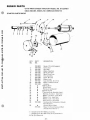
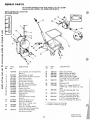
REPAIR PARTS
10
11
14
26
C
55
3
53
26
L
U
55
lE]
49
S
.,.. ...,....,
-, r
I]
~3
t:::S::>
[]J53 •
~
.,.... -...,... '
......
~
57
~
/
79
57
75
' 76
77
78
. 14 -
22
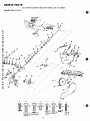
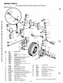
REPAIR PARTS
another free manual from www.searstractormanuals.com
e
fa
GT/18 TWIN-GARDEN TRACTOR--MODEL NO. 917.257061
STEERING, AND FINAL DRIVE
KEY
NO.
PART
NO.
1
2
3
4
5
6
7
8
9
10
11
12
13
14
15
16
17
18
19
Steering Wheel Insert
641J
STD523710 *Hex Bolt 3/8·16 xl
STD551137 * Lockwasher 3/8
1559P
Washer 7/16 x 1 x 10 Ga.
4820R
Steering Wheel
5003P
E·Ring
Cap
9007H
Rubber Bushing
5949H
7903R
Foot Rest· L.H.
Decal (Attach. Clutch)
8900R
Foot Rest· R.H.
7904R
1553P
Washer 57/64 xl· 1/4 x 16 Ga.
Woodruff Key 3/16 x 5/8
9858M1
634A626
Steering Shaft and Pinion
7987R
Control Knob
Shift Rod Bracket
6442H
Cotter Pin 3/16 x 1
2511P
634A22A
Belt Guide
Range Shift Rod
6471H
Transmission Bracket
9594R
Seat Stop
8674R
Rear Tire 23 x 10.00 . 12
8054R
795R
Tire Valve
469J
Rear Wheel
9428R
Fender· R.H.
Wheel Hub· Rear
634A692
7563R
Axle Thrust Washer
5845R
Retaining Ring
9427R
Fender· L.H.
2656R
Bracket - Tail Light
Seat Stop Bracket
125J
Fuel Tank Retainer
126J
8141H
Seat Spring Reinforcement
Seat Spring
7898R
634A776
Seat Plate Weldment
634A532
Seat Bracket Weldment
7897R
Bracket, Seat Pivot
268J
Seat
Fuel Gauge
7886R
Fuel Tank
7885R
Fuel Line Clamp
6999R
2751 R
Clip· Fuel Line
Fuel Line (Long)
7834R
In-Line Filter
266J
7833R
Fuel Line (Short)
9297R
Clip· Fuel Line
20
21
22
23
24
25
26
27
28
29
30
31
32
33
34
35
36
37
38
39
40
41
42
43
44
45
45A
DESCR IPTION
DESCRIPTION
KEY
NO.
PART
NO.
46
Sq Nk. Sht. Shld Carr. Bolt 3/8
x 1 Gr. 5
STD551037 ·Washer 13/32 x 13/16 x 16 Ga.
1519P
Washer 15/32 x 1 x 12 Ga.
5394H
Locknut 3/8 UNC
STD523712 * Hex Bolt 3/8 . 16 xl· 1/4
1557P
Washer 13/32 x 13/16 x 11 Ga.
47
48
49
50
51
53
54
55
56
57
58
59
60
61
62
63
64
65
66
70
71
72
73
74
75
76
71
78
79
80
81
82
83
61P
STD541037
STD523715
3022P
STD523107
STD551131
STD533707
1304H
3034P
STD551143
STD541043
STD522507
STD551025
STD551125
STD541025
STD533107
STD551031
1685H
STD523707
52P
1578P
1560P
STD551150
STD541050
STD523108
9547R
372J
124J
279J
53J
1122J
16
*Hex Nut 3/8 . 16 UNC
*Hex Bolt 3/8 . 16 x 1 1/2
Hex Bolt 3/8·16 x 7/8
* Hex Bolt 5/16 . 18 x 3/4
* Lockwasher 5/16
*Sq. Neck Carriage Bolt 3/8 . 16 x 3/4
Hub Bolt
Hex Bolt 7/16·14 xl
* Lockwasher 7/16
*Hex Nut 7/16·14 UNC
"Hex Bolt 1/4·20 x 3/4
*Washer 9/32 x 5/8 x 16 Ga.
* Lockwasher 1/4
*Hex Nut 1/4·20 UNC
*Short Shoulder Sq. Neck Carri~ge
Bolt 5/16 . 18 x 3/4
*Washer 11/32 x 11/16 x 16 Ga.
Lock Nut 5/16 . 18 UNC
*Hex Bolt 3/8 . 16 x 3/4
Carriage Bolt 1/2·13 xl· 1/4 Gr. 5
Washer 3/4 xl· 1/8 x 11 Ga.
Washer 17/32 xl- 1/2 x 11 Ga.
* Lockwasher 1/2
*Hex Nut 1/2·13 UNC
* He x Bo It 5/1 6 . 18 x 7/8
Rubber Grommet
Steering Wheel Decal
Rubber Bumper
Decal
Warranty Tag
Owners Manual
*STANDARD HARDWARE .. PURCHASE LOCALLY
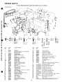
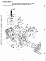
REPAIR PARTS
GT/18 TWIN-GARDEN TRACTOR--MODEL NO. 917.257061
another free manual from www.searstractormanuals.com
BRAKE AND CLUTCH
e
o
B
A
F
E
H
G
J
I:: 1 1 i I:: 1,!: ,~
52
I
cr:::::IJ
5
'15~
54
c
58
6
(II) 60
57
,53
- 16-
(HJ62
=
66
CID 67
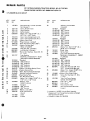
REPAIR PARTS
GT/18 TWIN-GARDEN TRACTOR--MODEL NO. 917.257061
another free manual from www.searstractormanuals.com
BRAKE AND CLUTCH
-
OESCR IPTION
KEY
NO.
PART
NO.
1
2
3
4
5
6
7
8
9
10
11
12
14
15
16
17
18
19
20
21
22
23
24
25
26
27
28
29
30
31
32
33
34
35
36
36A
Insert Clutch-Brake
8899R
Foot Pedal
8882R
Foot Pedal Bracket
8765H
Spring
9008H
111 J
Foot Pedal Shaft
E-Ring
5001P
Washer 21/32 x 7/8 x 16 Ga.
1527P
Cotter Pin 1/8 x 3/4
2505P
Brake Rod - Front
2202R
Turnbuckle
6417H
ST0541037 *Hex Nut 3/8 - 16 UNC
Safety Start Actuator
7823R
Bushing
2201 R
Washer 13/32 x 13/16 x 11 Ga.
1557P
Spring Washer
2263R
Parking Brake Yoke
9686R
Roll Pin
175H
Lock Bracket Assembly
634A887
Parking Brake Spacer
2221 R
Spring Washer
5999H
Handle Grip
4379H
Parking Lock Handle Assembly
626A341
Gripco Centerlock Nut 3/8 - 24 UNF
7810H
Brake Rod Assembly
626A365
Brake Band and Lining
634A167
Brake Bracket Assembly
634A168
Lock Nut 1/2 - 20 UNF
9204H
Brake Drum
7648Hl
634A899
Brake Arm Assembly
Woodruff Key
9858Ml
Clutch Rod
9288R
2514P
Cotter Pin 1/4 x 1
Spring
6486H
ST0551050 *Washer 17/32 xl· 1/16 x 21 Ga.
4939M
Retainer Spring
544J
Hose Shield
r
KEY
NO.
PAR
NO.
37
38
39
40
41
42
43
44
45
46
47
48
49
50
51
52
53
54
55
56
57
58
634A754
6636H
5002P
634A898
ST0541043
ST0551143
1544P
6635H
1520P
6479H1
3262P
2692R
6461H2
ST0522507
ST0551125
ST0623710
ST0551037
ST0541337
5142H
3022P
ST0551137
3164P
59
60
61
62
63
64
65
66
67
DESCRIPTION
Idler Bracket Weldment
Idler
ERing
Steering Arm Assembly
• Hex Nut 7/16 - 14 UNC
• Lockwasher 7/16
Washer 15/32 x 15/16 x 16 Ga.
Flat Idler
Washer .4691.0. x 1 -1/8 x 11 Ga.
Belt Fingel
Hex Bolt 7/16 - 14 x 2 - 1/2
V-Belt
Pulley, Transmission
*Hex Bolt 1/4 - 20 x 3/4
* Lockwasher 1/4
*Fin. Hex Bolt 3/8 - 24 x 1
*Washer 13/32 x 13/16 x 16 Ga.
"Hex Jam Nut 3/8 - 24 UNF
Roll Pin
Hex Bolt 3/8 - 16 x 7/8
• Lockwasher 3/8
Flat Hd. Machine Screw - Underl\ut
3/8 - 16 x 3/4
11 P
Sq. Neck Carriage Bolt 1/4 - 20 x 5/8
ST0541025 *Hex Nut 1/4 - 20 UNC
ST0523108 *Hex Bolt 5/16 - 18 x 7/8
1685H
Locknut 5/16 18 UNC
3244P
Hex Bolt 1/4 - 28 x 5/8 Gr. 5
9071 H
Huglock Nut 1/4 - 28 UN F
3326P
Hex Hd. Mach. Screw 6 - 32 x 1
1567P
Washer 5/32 x 3/8 x 20 Ga.
562P
Center lock Nut 6 . 32 UNC
'STANOARO HARDWARE··PURCHASE LOCALLY
. 17 .
REPAIR PARTS
GT/18 TWIN-GARDEN TRACTOR--MODEL NO. 917.257061
SCHEMATIC DIAGRAM
BATTERY
~------------------------~II~------------------------~
+
12V
STARTER
/........
...........
another free manual from www.searstractormanuals.com
NEuTRAL
SAFE SW.
...........
........
~
IGNITION
SWITCH
r
........
SOLENOID
0------4' Co---o-,\",,""""A-~V-o---q
ATTACHMENT
SAFESW.
S
FUSE
r-<l---O B
R
RECTIFIER
0--------_
30 AMP.
A
CHARGING COIL
COIL
PRI.
CAPACITOR
POINTS
SEC.
PLUG
SERVICE HOUR
METER
PLUG
.-----0
HEADLIGHT
15 AMP.
POSITION
OFF
NONE
RUN
B·R·I·A
START
HEADLIGHT
CIRCUIT
TAILLIGHT
LIFT
MOTOR
ACC'Y.
B·R·I·S
UP-DOWN
SWITCH
CHASSIS
GROUND
_HI.
REPAIR PARTS
GT/18 TWIN-GARDEN TRACTOR--MODEL NO. 917.257061
ELECTRICAL
another free manual from www.searstractormanuals.com
8
-
Cit
9
7
l
)
lOA
60
19
B
A
"if
~47
46
[ ] ) 48
C
T
49
0
52
(il) 53
c;:;;e,
~50
a:::Ii
51
E
i
=
a:::D
F
"""" 54
55
161514
G
i
8
~
51
a:D
KEY
NO.
KEY
NO.
PART
NO.
DESCR IPTION
1
2
6452R
5554P
3
4
5
6
7
8
9
10
10A
11
12
13
14
15
16
17
18
19
20
21
22
23
24
26
27
28
29
30
31
32
8768H
8784Hl
8031 R
9197H
3748M
1506P
7955R
2685R
88J
4171R
8859R
2235R
7755R
7754R
8027R
116J
225J
8030R
8089H
8292H
8293H
8291H
7763R
7794R
7793R
2212R
6347R
2753R
8066R
7552H
Headlight
33
34
Phillips Pan Hd. Thd. Cutting Screw
No. 10 - 16 x 1/2
35
Mounting Clip
36
37
Rubber Spacer
Headlight Ground Wire
38
Hose
39
40
Wing Nut 1/4 . 20 UNC
41
Washer 9/32 x 5/8 x 16 Ga.
42
Battery Clamp
Battery Bolt
43
44
Battery Bolt
45
Insulated Clip
46
Battery - "Sears Die·Hard"
Cable· Solenoid to Starter
47
Safety Switch
48
Solenoid
49
Wire· Ground to Solenoid
50
Battery Ca ble
51
Terminal Cover
52
Light Harness
53
Taillight (Inc. Key No's. 21,22, & 23)
54
Lens· Taillight
55
Housing· Taillight
56
Bulb No. 18952 Candle Power
57
Maintenance Meter
58
Light Switch Knob
59
Light Switch
60
Fuse· 15 Amp.
61
Fuse· 30 Amp.
62
Battery Cable· Ground
Maintenance Meter Bracket
Key Set
- 19·
14
H
J
~52
55
l
K
i- 1
57
57
58
58
c - = 59
58
cr::D 56
=59
q.,-, 52
(il) 56
-
50
51
13
PART
NO.
2683R
8656R
9565R
7753R
9698R
8984R
566P
7319R
1518P
9349R
8985R
5320R
8615R
5534P
STD551131
STD541331
STD522506
STD551125
STD541025
STD551110
STD541110
1402P
STD522507
STD541010
STD511007
1404P
STD551010
51J
302J
3357P
"STANDARD
~
a:D
M
50
51
i
62
~52
(il)
56
a:::D 56
DESCRIPTION
Ignition Switch
Terminal Identifier
Wire Harness· Main
RegulatOl . Rectifier
Wire, Ground Lift Switch
Switch, Elec. Lift
Hex Nut, Steel 7/16·32 NS· 2A
Lockwasher, Internal Tooth
Washer 15/32 x 11/16 x 16 Ga.
Switch Plate
Lift Motor Harness
Clip, Wire
Clip
Slotted Hex Indented Hd. Self Tapping
Screw No. 10·24 x 3/8 Type 1
"Lockwasher 5/16
"Hex Jam Nut 5/16·24 UNF
"Hex Bolt 1/4·20 x 5/8
"Lockwasher 1/4
"Hex Nut 1/4·20 UNC
"Lock washer No.1 0
"Hex Nut No. 10·32 UNF
Ext. Tooth Lockwasher 3/8
"Hex Bolt 1/4 20 x 3/4
"Hex Nut No. 10·24 UNC
*Sltd. Truss Hd. Mach. Screw 10·24 x 3/4
Ext. Tooth Lockwasher No.1 0
"Washer 7/32 x 1/2 x 18 Ga.
Solenoid Terminal Cover
Wire Guard
Sltd. R. H. Mach. Screw No.1 0 . 24 x 1/2
HARDWARE .. PURCHASE LOCALLY
REPAIR PARTS
GT/18 TWIN-GARDEN TRACTOR--MODEL NO. 917.257061
TRANSAXLE
.____ 1
another free manual from www.searstractormanuals.com
2
·20·
REPAIR PARTS
GT/18 TWIN-GARDEN TRACTOR--MODEL NO. 917.257061
TRANSAXLE
KEY
NO.
PART
NO.
DESCRIPTION
another free manual from www.searstractormanuals.com
633A92
2
3
4
5
6
7
8
9
10
11
12
13
14
15
16
17
18
19
20
21
22
23
24
25
26
27
28
29
30
31
32
33
34
35
36
37
38
39
40
41
42
43
Transaxle Assembly Less Brake DI urn
& Shift Lever (I nCo Key No's. 13 thru 80)
633A82
Gear Shift Lever Assembly (Inc. Key
No's. 3 thru 12 and 81)
Control Knob
7987R
9635R
Gear Shift Lever
Gear Shift Ball Cover and Pin
633A85
9013R
Gear Shift Cap
Shift Lever Guide Ball
8739H1
Spring
4924H
STD551043 "Washer 15/32 x 59/64 x 16 Ga.
Shift Mechanism Seal
8105R
1525P
Washer 9/16 x 15/16 x 11 Ga.
2505P
Cotter 1/8 x 3/4
Needle Bearing
3039R
Axle Thrust Washer
6256H
Centerlock Gripco Nut 3/8 - 24 UNF
7810H
Final Drive Gear
8662H
Axle Shaft and Gear
633A73
Bushing - Differential Pinion
6252H 1
Differential Pinion
8657H
Differential Carrier
6263H1
Hex Bolt 3/8·24 x 3 - 1/4
3056P
1 " Thread Length
Gear Case and Bearings - L.H.
633A89
Pipe Plug 1/2 -14 N.P.T.
4002P
90 Street Elbow 1/2-14 N.P.T.
4003P
Sintered Iron Bearing
992R1
Oil Seal
7393R
Lock Nut
9204H
Oil Seal
6271 H
Pipe Plug 1/4 - 18 N.P.T.
4001P
Lockwasher 5/16 Extra Heavy
1007P
STD523115 "Hex Bolt 5/16 -18 xl - 1/2 Gr. 5
Dowel Pin
6277H
Spring - Shift Fork Detent
6272H
Steel Ball
7392M
Shift Fork High - Low Range
6260H
High - Low Range Shift Fork Shaft
6217H
Needle Bearing
8118M
Thrust Bearing Race
6266H
High - Low Range Shift Shaft
6215H
3rd Reduction Gear Shaft
6221H
4th Reduction Pinion
8659H
Woodruff Key
2228M
633A32
3rd Reduction Shaft and Gear
(Inc. Key No's. 40, 41 & 42)
- 21 .
KEY
NO.
PART
NO.
44
45
46
47
48
49
50
51
52
53
54
55
56
57
58
59
8119M
Needle Bearing
6275H
Gasket - Gearcase
8117M
Needle Bearing
7396H
Thrust Bearing Race
6276H
Snap Ring - Crescent Type
633A 14
High - Low Range Gears and Hub
633A33
4th Reduction Shaft and Gears
7398H
Needle Bearing
7395H
Thrust Bearing Race
633A31
2nd Reduction Shaft and Gears
1370H
Thrust Bearing Race
4895H
Needle Bearing
633A30
Speed Change Gears and Shaft
5001P
E-Ring
4894H
Needle Bearing
6231H
Low Speed Pinion
9858M1
Woodruff Key
6218H
Input Shaft
633A 11
Intermediate and High Speed Pinions
6216H
Shift Fork Shaft
4219R
Shift Fork - L.H.
4926H
Snap Ring - Crescent Type
6262H
Shift Fork - R.H.
1153R
Reverse Idler Gear
7392H
Reverse Id ler Thrust Washer
7384H
Reverse Idler Shaft
1167R
Sealing Washer
541P
Hex Jam Nut 7/16 - 20 UNF
STD541031 "Hex Nut 5/16·18 UNC
6270H
Oil Seal
Gear Shift Gate
75J
STD551131 "Lockwasher 5/16
STD523108 "Hex Bolt 5/16 - 18 x 7/8
6274H
Gasket - Shift Ball Cover
633A90
Gear Case, Reverse Idler Shaft
and Bearings R.H.
5855H
Pressure Relief Valve
6269H
Oil Seal
7835M
Woodruff Key
60
61
62
63
64
65
66
67
68
69
70
71
72
73
74
75
76
77
78
79
80
81
DESCRIPTION
"STANDARD HARDWARE--PURCHASE LOCALLY
REPAIR PARTS
another free manual from www.searstractormanuals.com
GT/18 TWIN-GARDEN TRACTOR--MODEL NO. 917.257061
FRONT AXLE
----~
,I
~~1
,
~22
!~8
:~91
I~
I
1~81
'~
:..... -9:
I
'~I
I
I
J
21A
,v'
24
:~~22
KEY
NO .
1
2
3
4
5
6
7
8
9
10
11
12
13
14
15
16
17
18
19
20
21
22
23
24
25
PART
NO.
5000P
1528P
1309H
634A521
3294P
634A277
9040H
7810H
2515R
7838R
DESCRIPTION
E-Ring
Washer 13/16 xl · 1/4 x 14 Ga .
Bearing
Front Axle w/Bearings (Inc. Key No.3)
Hex Bolt 5/8 . 11 x 5 Grade 5
Spindle Complete . R.H.
Flanged Bearing
Gripeo Locknut 3/8 . 24 UNF
Hardened Washer
Tie Rod and Joints (Inc. Key No's. 15, 16,
17,18 & 19)
Grease Fitting
6855M
1505P
Washer 9 /32 x 1/2 x 14 Ga.
4764H
Huqlock Nut 5/8 x 11 UNC
Spi ndle Complete L.H .
634A278
Tie hod Joint (R .H . Threadl
8515R
ST0541350 'Hex ~~ m Nut 1/2·20 (R .H . Thread)
Tie Rod and Nuts (Inc. Key No '5. 16 & 18)
634A819
Hex Jam Nut 1/2 . 20 (L.H. Thread)
559P
Tie Rod Joint (L.H. Thread)
8514R
Steer ing Gear Sector and AI m
634A813
1552P
Washer 4964 xl· 1/4 x 16 Ga.
Grease Fitting
6842M
Dr ag Link and Joints
7837R
Steefl ng Bell Crank Weldment
634A98
2169R
Front Tire 16 x 6.50·8
.22.
KEY
NO.
26
27
28
29
30
31
32
33
34
PART
NO.
6856M
795R
467J
1562P
8798H
8785H
4831H
8763H
3008P
OESCR I PTION
Grease Fitting 1/4·28 Taper Thrd.
Tire Valve
Front Wheel and Bearings
Washer 25 /32 xl · 1/2 x 16 Ga.
Roll Pin 5/32 x 1
Wear Washer
Elastic Nut 3/4 . 16 UNF
Du st Cap ·Outer
He x Bolt 5/16 - 18 x 1/ 2
'STANDARD HARDWARE ·· PURCHASE LOCALLY
REPAIR PARTS
GT/18 TWIN-GARDEN TRACTOR--MODEL NO. 917.257061
ONAN ENGINE--MODEL NO. B48M-GA018/3417A
FUEL SYSTEM GROUP
~15
another free manual from www.searstractormanuals.com
14
7
2
5
KEY
NO.
PART
NO.
140-1169
2
142-0568
3
4
5
6
145-0438
154-1468
154-1744
800-0033
800-0034
7
8
10
11
12
13
14
140-1198
850-0045
503-0740
140-1215
140-1213
140-1216
140-1168
DESCRIPTION
Tube, Air Intake (Air Cleaner to
Blower Housing)
tCar buretor, Gasol i ne (with I ntegra I
Fuel Pump)
*Gasket, Carburetor Mounting
Manifold, Intake
*Gasket, Intake - Manifold
Screw, Hex Head Cap 5/16 . 18 x 2
Screw, Hex Head Cap 5/16 . 18 x 2 1/4
Support, Air Cleaner
Washer, Spring Lock (5/16")
Hose, Fuel Pump Vacuum
*Gasket, Air Cleaner Mtg.
Housing, Ari Cleaner
Element, Air Cleaner
Cover, Air Cleaner
KEY
NO.
PART
NO.
DE:SCR IPTION
15
17
865·0020
800·0023
18
19
850-0040
815-0463
20
22
23
25
26
27
28
140·1259
140-1313
518-0328
800-0003
862-0001
853-0013
403-1021
Nut, Wing - Air Cleaner (1/4 - 20)
Screw, Hex Head Cap (1/4 - 20 x
1 - 3/8")
Washer, Spring Lock (1/4")
Screw, Round Head with Nylon Seal
(No. 10 - 32 X 5/8")
Wrapper, Air Cleaner Element
Bracket, Air Cleaner Support
Clip, Bracket, Cable
..
Screw, Hex Head Cap (1/4 - 20 x 1/2 )
Nut, Hex - Steel (1/4 - ~)
Washer, Lock - ET (1/4 )
Bracket, Lifting
t - See separate group for components.
* . Included in Gasket Kit, page 29.
- 23-
REPAIR PARTS
GT/18 TWIN·GARDEN TRACTOR .. MODEL NO. 917.257061
ON AN ENGINE .. MODEL NO. B48M·GA018/3417A
CARBURETOR PARTS GROUP
I. 5,,·",
another free manual from www.searstractormanuals.com
~
;"----10
I
2
14
20
A
12
25
/
.---23
/~24
r4f'
~9
'"
'\
~
1
1
i
18
KEY
NO.
PART
NO.
1
2
3
4
5
6
7
8
9
10
11
12
13
14
15
16
142~574
142~568
142·0573
142·0534
142~535
142·0536
142~537
142·0538
142'()064
142·0334
142·0539
142·0540
142·0541
142'()542
142·0572
142·0555
142·0544
13
3
7
6
15
26
DESCRIPlluN
Carburetor Assembly, Complete
Body Assembly, Lower
Sleeve Assembly
*Shaft Assembly, Throttle
tPacldng, Shaft
Shaft Assembly, Choke
·Valve Plate Assembly
Fly, Throttle
Screw, Throttle Stop
• Screw, Fly Mounting
Screw, Bowl Cover Mounting
Screw, Pump Cover
tGasket, Base to Diaphragm
tGasket, Plate to Base
tGasket, Sleeve Assembly to Base
"Diaphragm, Pump
Spring, Throttle Stop Screw
KEY
NO.
PART
NO.
17
18
19
20
21
22
23
24
25
26
27
28
142·0282
142'()545
142·0546
142·0547
142·0548
142·0016
142·0549
142·0550
142·0551
142·0552
142·0553
142·0554
142·0571
142·0570
DESCRIPTION
*Spring, Idle Needle
*Spring, Pump Diaphragm
Fly, Choke
Float and Lever Assembly
*Shaft, Float Lever
*Needle, Idle
Needle Assembly, Power
tGasket, "0" Ring
Cover. Pump
*Plate, Pump Spring
'Valve Assembly, Float
CliP. Float Valve
'Gasket Set (Includes Parts Marked tl
Repair Kit (Includes Parts Marked ")
t· Included in 142·0571 Gasket Set.
" . Included in 142·0570 Repair Kit.
·24·
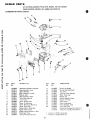
REPAIR PARTS
GT/18 TWIN-GARDEN TRACTOR--MODEL NO. 917.257061
ONAN ENGINE--MODEL NO. B48M-GA018/3417A
I
GOVERNOR, STARTER,
CHARGING ALTERNATOR AND
BLOWER HOUSING GROUP
another free manual from www.searstractormanuals.com
t;
fa
·~14
~24
~25
26
19
KEY
3029
28
27
PART
NO.
DESCRIPTION
KEY
NO.
PART
NO.
DESCRIPTION
1
3
518-0176
526-0214
19
815-0261
5
815-0436
6
8
9
10
11
150-1214
150-1343
150-1269
150-1576
870-0278
20
21
22
23
24
134-3401
150-1418
150-1433
134-2989
815-0290
25
526-0021
12
13
150-1350
518-0004
26
27
134-3400
191-0933
28
526-0113
14
15
16
167-0188
191-1102
813-0108
29
30
850-0045
800-0028
18
870-0131
Clip, Throttle Cable
Flat Washer 17/64 I. D. x 1/2
x 1/16
Screw, Hex Cap - Flange Locking
(1/4 - 20 x 1/2)
Spring, Governor
Bracket, Governor Mounting
Bushing Governor Control
Arm, Governor Control
Clip, Governor Control Rod to
Governor Arm
Rod, Governor Control
Clip, Governor Control Rod to
Carburetor
Clip, Alternator Lead Support
Stator, Charging Alternator
Screw Round Head - Steel
No.l0 - 32 x 1 - 1/2"
Nut, Hex No.1 0 - 32
31
32
134-3213
815-0378
Screw, Hex Head Cap
(1/4 - 20 x 7/16")
Housing, Blower
Stud, Governor
Bracket, Governor Control
Housing, Cylinder Ari - Left
Screw; Hex Head Cap (1/4 - 20
x 5/8' )
Washer, Flat - Steel (17/64" 1.0.
x 3/4" 0.0. x 1/16" Thick)
Housing, Cylinder Air - Right
Starter, 12 Volt (For Components
see separate group)
Washer, Flat - Steel (11/32" 1.0. x
1" 0.0. x 3/32" Thick)
Washer, Spring Lock (5/16")
Screw, Hex Head Cap
(5/16 - 18 xl")
Guard, Blower Housing
Screw, Ind. Hex Head w/ET
(No. 14 x 1/2")
NO.
- 25-
REPAIR PARTS
GT/18 TWIN-GARDEN TRACTOR--MODEL NO. 917.257061
ONAN ENGINE--MODEL NO. B48M-GA018/3417A
IGNITION GROUP
r · .~
another free manual from www.searstractormanuals.com
--17
3
4
10
11
~
V'3
14
KEY
NO.
PART
NO.
160·1210
2
812·0108
3
526·0008
3A
4
5
509·0065
160·1232
815·0358
6
7
8
850·0025
312·0196
802-0034
9
850-0038
10
11
12
13
14
15
16
160-1183
160-1219
160-1150
160-1151
336-2132
167-0237
167-1595
167-1596
166-0535
166-0604
503·0311
17
18
19
20
DESCRIPTION
Box Assembly, Breaker (Includes
Parts Marked *)
t*Screw, Machine· Round Head
(No. 10-14 xl ·1/2")
t"Washer, Flat (13/64" 1.0. x 7/16"
0.0. x 1/32" thick)
t*Retainer, "0" Ring
·Cover . Breaker Box
*Screw, Tapping · Hex Head (No. 8 - 32
X 5/16")
"Washer, Lock· Spring (No.8)
"Condenser, Ignition
"Screw Cap - Socket Head (1/4 - 20
l
x 3/4' )
"Washer, Lock - Spring· High Collar
(1/4")
·Point Assembly , Breaker
"Base, Breaker Box
+"Gasket, Breaker Box
Plunger , Breaker Point Assembly
Lead, Breaker Points to Coil
Plug, Spark
Cable, Spark Plug (17")
Cable, Spar k Plug (15")
Coil, Ignition
Nut, Coil Cabl e (Part of 166-0535 Coil)
Clamp, Coil Mounting
"PARTS INCLUDED IN 160·1210 BREAKER BOX
ASSEMBL Y .
+INCLUDED IN GASKET KIT 168-0130.
tlNCLUDED IN 160-1232 COVER
- 26-
REPAIR PARTS
GT/18 TWIN-GARDEN TRACTOR--MODEL NO. 917.257061
ONAN ENGINE--MODEL NO. B48M-GA018/3417A
STARTER PARTS GROUP
another free manual from www.searstractormanuals.com
9
10
20
KEY
NO.
1
2
3
4
5
6
7
8
9
10
11
12
13
14
15
16
17
18
19
20
21
22
23
PART
NO.
191-0933
191-1034
191-1045
191 -1046
191-1035
191-1047
191-1036
191-1048
850-0040
191-1037
191-1038
191-1039
Jt.
Jt.
Jt.
Jt.
Jt.
Jt.
Jt.
Jt.
Jt.
Jt.
191-1040
Jt.
191 -1041
DESCRIPTION
Starter, 12 Volt (Complete)
Cover, Dust
Nut. Stop
Washer , Stop Nut
Spring, Anti-drift
Spacer, Dust Cover
Drive Assembly
Screw, Hex Cap
Washer, Lock
Cap, Assembly, Dri ve End
Washer , Armature Thrust
Armatur e
t*Spring, Brus h
tBrush Holder
tScrew and Lockwasher
t · Bru sh, Ground
t· Stud and Brus h Assembly , Input
tBushing, Insulation Input Stud
tWasher, In sulation - Input Stud
tWasher, Flat · Input Stud
tWasher, Lock· Input Stud
tNut, Securing · Input Stud
Cap As semb ly, Commutator (Includes
Parts Marked t)
Housing, Start er Motor
Repair Kit , Brush, Srlring and Stud
(Includes Parts Marked')
t - Included in the 191·1040 Cap Asse mbly.
'. Included in the 191 -1041 Brush, Spring and Stud Kit.
Jt. . Not Sold Separately
- 27-
REPAIR PARTS
GT/181WIN-GARDEN TRACTOR--MODEL NO. 917.257061
ONAN ENGINE--MODEL NO. B48M-GA018/3417A
CYLINDER BLOCK GROUP
another free manual from www.searstractormanuals.com
14----
.-----
15
21
~
I
21~~
"
'-- -'-..
-- 33
39
· 28·
REPAIR PARTS
I
GT/18 TWIN-GARDEN TRACTOR--MODEL NO. 917.257061
ONAN ENGINE--MODEL NO. B48M-GA018/3417A
CYLINDER BLOCK GROUP
KEY
NO.
PART
NO.
DESCRIPTION
another free manual from www.searstractormanuals.com
110-2621
'It
2
3
4
5
6
7
8
9
10
11
12
13
14
15
16
17
18
19
20
21
22
23
24
25
26
27
Block Assembly, Cylinder (Includes
Parts Marked t)
123·1174
Spring, Breather Valve
123·1175
Valve, Breather
123·1173
Baffle, Breather
526-0018
Washer, Flat· Steel (17/64" I.D. x
5/8" O.D. x 1/16" Thick)
110·2274
Cover, Valve Compartment (L.H.)
110·1879
Cover, Valve Compartment (R.H.)
110·1921
xGasket, Valve Cover
517·0048
tPlug, Extension· Camshaft
104·0776
tShim, Rear Bearing Plate (.005 ")
110·2287
xGasket, Cylinder Head
HEAD, CYLINDER
110-2564
Riqht Side (No.2 Cylinder)
800·2563
Left Side (No.1 Cylinder)
800·0051
tScrew, Hex Head Cap· Steel (3/8·16
xl· 1/4")
123·1277
Tube, Breather
BEARING, CRANKSHAFT· REAR
(INCLUDES THRUST WASHER)
101·0450
tStandard
101·0450·02 .002" Undersize
101·0450·10 .010" Undersize
101·0450·20 .020" Undersize
101·0450·30 .030" Undersize
104·0575 t*Washer, Crankshaft Bearing Thrust
101·0415 xtGasket, Bearing Plate
tPlate, Bearing (Excludes Bearings)
101·0439
tBearing, Camshaft (Precision)
101·0405
509·0041 xtSeal, Bearing Plate
516·0072
tPin, Main Bearing Stop
526·0063
Washer, Flat· Copper (17/64" I.D. x
7/16" O.D. x 1/32" Thick)
110·0893
Retainer, Valve
TAPPET, VALVE
115-0006
Standard
115·0006·02 .002" Oversize
115-0006-05 .005" Oversize
tWasher, Lock (3/8")
850-0050
120-0735
tTube, Crankcase Oil
VALVE
110·1808
Intake
110-1809
Exhaust
KEY
NO.
PART
NO.
28
INSERT, VALVE SEAT
EXHAUST
tStandard
110·1824
110·1824·02 .002" Oversize
110·1824·05 .005" Oversize
110·1824·10 .010" Oversize
110·1824·25 .025" Oversize
INTAKE
110·0197
tStandard
110·0197·02 .002" Oversize
110·0197·05 .005" Oversi ze
110·0197·10 .010" Oversize
110-0197·25 .025" Oversize
526·0122
Washer, Flat· Steel (11/32" I.D. x
23/32" O.D. x 10 Gauge)
110·1807
tGuide, Valve
Spring, Valve
110·0539
110·0639
Lock, Valve and Spring Retainer
*BEARING, CRANKSHAFT· FRONT
(FLANGED)
101-0432
tStandard
101·0432-02 .002" Undersize
101·0432·10 .010" Undersize
101·0432·20 .020" Undersize
101·0432·30 .030" Undersize
Screw, Hex Head Cap (3/8 . 16 x
800-0046
3/4") . Cylinder Block Wet Hole
Washer, Flat· Copper (25/64" 1.0. x
526·0066
9/16" O.D. x 1/16" O.D.)
110·0068 xtGasket, Valve Guide (Intake)
Screw, Hex Head Cap (1/4·20 x
800·0010
1 ·3/4")
Tube, Fuel Pump Vacuum
149·1299
SCREW, HEX HEAD CAP
5/16·18x 1-5/8"
800·0540
5/16 - 18 x 2"
800·0541
Filter, Breather Tube
123-0865
Stud, Cylinder Block Wet Hole
520-0820
(Lower)
29
30
31
32
33
34
35
36
37
38
39
40
41
DESCRIPTION
t - Included in 110·2397 Cylinder Block Assembly.
* - Replacement Front Flange Bearing replaces unflanged
bearing and thrust washer.
x . Included in Gasket Kit 168-0130
- 29-
REPAIR PARTS
PISTt:&:J-J~HEEL, CAMS~NE
another free manual from www.searstractormanuals.com
CRANKSH
AND
GT /18 TWIN-GARDE
ONAN ENG
N TRACTOR··MO
AFT
•.MODEL NO. B48M.G A018/3417A
DEL NO. 917.257061
6
23
'-,
30
~18
4
V---
14
5
14
r1
13
- 30-
12
11
REPAIR PARTS
GT/18 TWIN-GARDEN TRACTOR--MODEL NO. 917.257061
ONAN ENGINE--MODEL NO . .B48M-GA018/3417A
CRANKSHAFT, FLYWHEEL, CAMSHAFT
AND PISTON GROUP
KEY
NO.
1
DESCRIPTION
150· 1519
150-0078
150·1520
510-0015
104·0779
134-3506
18
19
20
21
Hu b
R in g, Ca mshaft Center Pin
Cup, Governor
Ba ll , Fly - Governor
Gear, Ring - Flywheel
Flywhee l (Includes Ring Gear and
Mag net fl ing)
105-0332
Gear , Camshaft (Includes Flyball
Spacer a nd Pl ate)
104-0032
Gea r , Crankshaft
Ke y (112" Dia meter x 1/8")
515-0001
105-0402
Ca mshaft (Includes Center Pin)
150-0075
Pin , Camshaft Center
PISTON AND PIN (INCLUDES RETAINING RINGS)
112-0151
Stan da rd
112-C151 -05 .005" Overs ize
112-0151 -10 .010" Oversi ze
112-0151 -20 .020" Oversize
112-0151 ·30 .030" Overs ize
112-0151-40 .040" O versize
112-0122
Pin , Pis to n
518-0311
Ri ng , Pi st o n Pin Retaining
ROD ASSEMBLY, CONNECTING
114-0257
Sta ndard
114-0257-10 .010" Oversi ze
114-0257 -20 .020" Oversi ze
114-0257-30 .030" Oversize
RING SET, PISTON
113-0189
Standard
113-0189-05 _005" Oversi ze
113-0189-10 .010" Oversize
113-0189-20 .020" Oversize
113-0189-30 .030" Oversize
113·0189-40 .040" Oversize
114-0240
Bo lt, Special · Connect ing Rod
526-0017
Was her, Fl at Stee l
(15/32" 1.0 . x 1 - 1/4 '0.0 . x
1/4 " Thi c k)
870·0 302
Nut , Loc king (5/ 16 · 24)
Was her, Spring Lock (7/16")
850-0055
G uard, F ly w hee l
134·3508
Screw, Hex Head Ca p
104-0170
22
518·0014
23
24
25
26
27
105-0004
104 -0043
104-0996
815·0400
821 -0014
29
30
31
150-1257
150-0077
515·0227
lA
another free manual from www.searstractormanuals.com
PART
NO .
2
3
4
5
6
7
8
9
10
11
12
13
14
15
16
17
(7/16-14x4")
Ri ng , Re ta ining - Crankshaft Gear
Was her
Was her , Ca m shaft Gea r Th r ust
Was he r, Crankshaft Gear Retainer
Cr an ksh aft
Machin e Scre w Truss Head
Scre w, He x Hea d Ca p - Loc king
F la nge (511 6 - 18 x 1Ii')
Spacer, Gover nor Flywhee l
Pl at e , Go vern or Flyball
Key Kit
· 31 -
REPAIR PARTS
GT/18 TWIN-GARDEN TRACTOR--MODEL NO. 917.257061
ONAN ENGINE--MODEL NO. B48M-GA018/3417A
GEAR COVER, 01 L BASE AND
OIL PUMP GROUP
19
~71f
23
~6-©
another free manual from www.searstractormanuals.com
~~
3
~8--o
10
~5
6
-7
~-., ~-,.------- 2
----8
\
29~
28?-c
8
13
14
15
37
KEY
NO.
PART
NO.
103·0498
2
3
4
5
6
7
8
9
10
12
13
14
15
510·0105
150·1470
150·1187
815·0046
516·0130
509-0008
510·0014
509·0040
103-0408
123·1292
102-0693
505-0056
102-0741
16
17
120-0140
801-0050
18
19
120·0398
120-0491
20
120-0713
DESCRIPTION
Cover Assembly, Gear (Includes Parts
Mark ed *)
* Bearing, Gove rnor Shaft
*Shaft and Arm Assembly, Governor
'Yoke Governor Shaft
*Screw, Yoke Re taining
*Pin , Governo r Cup Stop
+*Seal , Oil · Go ve rnor Shaft
*Ball , Bearing · Governor Shaft
+*Seal, Gear Co ver
+Gasket, Gear Cover
Cap and Ind icator, Oil hll
+ Gasket, Oil Base Mounting
Plu g, Oil Drain
BASE, OIL
For Engines With Extende d
Oil Drain
Spring, Oil BY'Pass Valve
Screw , Hex Head Cap
(3/8 · 24 xl") . Oil By· Pass
Valve , Oil By . Pass
Pum p, Oil· Co mplete (NOTE:
Inte rnal parts not sold separately)
Intake , Oil Pump (Includes :
Cup, Screen and Pipe)
KEY
NO.
PART
NO .
21
22
23
24
120-0161
850-0050
850-0040
526-0065
28
505-0176
29
36
505-0158
526-0066
37
SOO-0056
38
800-0032
38
800·0545
39
800·0007
DESCRIPTION
+Gasket Kit, Oil Pump
Washer, Spring Lock (3/8")
Washer, Spring Lock (1/4")
Washer , Flat - Copper (21/64"
1.0. x 9/16" 0 .0 . x 1/16" Thick)
Nipple, Pipe - O il Drain (1/2 x 3-
112")
Cap, Pipe (1/2" )
Washer , Flat · Copper (25/ 64" 1.0 .
x 9/16" 0.0. x 1/16" Thick) - By - Pass
Valve
Screw , Hex Head Cap (3/8 - 16 x
2 - 1/2")
Screw, Hex Head Cap
1 . 3/4 ") . Gear Cover
Screw, He x Head Cap
2 - 3/4") - Gear Cover
Screw, He x Head Cap
(5/16 - 18 x
Mounting
(5/16 - 18 x
Mount ing
(1/4 - 20 xl")
* . Included in Gear Co ve r Asse mbly .
+ . Inclu ded in Gaske t Kit , page 29.
1122J-14. 12.77
- 32-
Printed in U.S.A.
another free manual from www.searstractormanuals.com
another free manual from www.searstractormanuals.com
MODEL NO.
917.257061
HD TO DRDIR
RIP IR P HT
MODEL NUMBER
The Model Number will be found on the Model Plate attached
to the Battery Heat Shield, in front of the Battery. Always
mention the Model Number when requesting service or repair
parts for your Garden Tractor.
REPAIR PARTS
All parts listed herein may be ordered from any SEARS, ROE BUCK AND CO. or SIMPSONS-SEARS LIMITED retail or
catalog store.
WHEN ORDERING REPAIR PARTS, ALWAYS GIVE THE
FOLLOWING INFORMATION:
•
•
•
•
THE
THE
THE
THE
PART NUMBER
PART DESCRIPTION
MODEL NUMBER
NAME OF MERCHANDISE
If the parts you need are not stocked locally, your order will be
electronically transmitted to a Sears Repair Parts Distribution
Center for "expedited handling".
SEARS SERVICE
Your Sears merchandise takes on added value when you discover that Sears has over 2,000 Service Units throughout the
country. Each is staffed by Sears-trained, professional techni cians using Sears approved parts and methods.
Sears. Roebuck and Co .. Chicago. Ill. 60684 . U.SA .
and Simpsons Sears Limited. Toronto. Canada