1
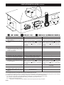
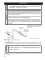
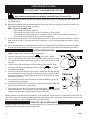
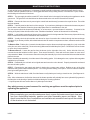
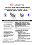
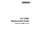
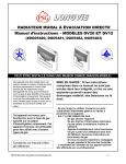
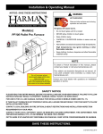
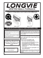
LONGVIE
VENTED WALL FURNACE
Owner’s Operation and Instruction Manual
Distributed By:
MODEL: DV20
MODEL: DV12
MAY BE INSTALLED IN A MANUFACTURED HOME (MOBILE HOME)
This Appliance may be installed in an aftermarket, permanently located, manufactured home
(USA only) or mobile home, where not prohibited by local codes.
This appliance is only for use with the type of
gas indicated on the rating plate. This appliance is not convertible for use with other gases,
unless a certified kit is used.
This appliance is only for use with
the type of gas indicated on the
rating plate. This appliance is not
convertible for use with other
gases.
Save this manual for
future reference.
USSC
WARNING: If the information in these instructions
are not followed exactly, a fire or explosion may
result causing property damage, personal injury,
or loss of life.
~Do not store or use gasoline or other flammable
vapors and liquids in the vicinity of this or any
other appliance.
~WHAT TO DO IF YOU SMELL GAS
* Do not try to light any appliance
* Do not touch any electrical switch; do not
use any phone in your building
* Immediately call your gas supplier from a
neighbor's phone. Follow the gas supplier's
instructions
* If you cannot reach your gas supplier, call
the fire department
~Installation and service must be performed by
a qualified installer, service agency or the gas
supplier.
1
INTRODUCTION
Your LONGVIE heater is especially designed to provide maximum comfort to you and your home. Its large solid injected
aluminum front grill assures the optimum use of the generated heat in the ambient, maintains normal temperatures behind
the heater to avoid sticking of particles, which would soil the wall. You can feel safe with absolute security guaranteed by:
•
Its thermocouple security valve, which cuts the supply of gas in the event of the heater extinguishing due to strong air
currents, momentary interruption of the supply of gas.
•
Its gas pressure regulator assures an optimum operational; function, avoiding peak pressures in the gas supply
affecting normal combustion.
•
Its gas tight combustion chamber, totally enameled, avoids gases which are caused by combustion, to contaminate
the air and ensures a useful , long lasting working life.
Long lasting working life...Guaranteed by the quality of its components and high technology applied in the process of
fabrication, and especially by the traditional vocation of LONGVIE to produce durable products for your maximum comfort
and satisfaction.
LOCAL CODES
Install and use the heater with care. The installation must conform with local codes or in the absence
of local codes, use the latest edition of The National Fuel Gas Code ANSI Z223.1/NFPA 54*. Natural
Gas and Propane Installation Code, CSA B149.1.
A manufactured home (USA only) or mobile home OEM installation must conform with the Manufactured Home Construction and Safety Standard, Title 24 CFR, Part 3280, or, when such a standard is
not applicable, the Standard for Manufactured Home Installation, ANSI Z225.1, or Standard for Gas
Equipped recreational Vehicles and Mobile Housing, CSA Z240.4.
*Available from:
American National Standards Institute, Inc.
1430 Broadway
New York, NY 10018
National Fire Protection Association, Inc.
Batterymarch Park
Quincy, MA 02269
GAS SPECIFICATIONS
MODEL
FUEL
MAXIMUM INPUT
DV12
Natural
10,000 BTU/hr
Liquid Propane
10,000 BTU/hr
Natural
18,000 BTU/hr
Liquid Propane
18,000 BTU/hr
DV20
MANIFOLD PRESSURE
Natural Gas
- DV12 - 5.8” w.c.
DV20 - 5.2” w.c.
Propane / LP Gas - DV12 - 10.8” w.c.
GAS INLET
SUPPLY
DV20 - 10.6” w.c.
3/8” NPT
MIN. PRESSURE
MAX. PRESSURE
Natural
7” W.C.P.
10.5” W.C.P.
Propane / LP
11.0” W.C.P.
13.0” W.C.P.
USE ONLY THE TYPE GAS SPECIFIED ON THE RATING PLATE
2
USSC
SAFETY RULES
1. Due to high temperatures, the appliance should located out of traffic and away from furniture and draperies.
2. Children and adults should be alerted to the hazards of high surface temperatures and should stay away to
avoid burns or clothing ignition.
3. Young children should be carefully supervised when they are in the same room as the appliance
4. Clothing or other flammable material should not be placed on or near the appliance.
5. Any safety screen or guard removed for servicing an appliance must be replaced prior to operating the
appliance.
6. Installation and repair should be done by a qualified service person. The appliance should be inspected
before use and at least annually by a qualified service person. More frequent cleaning may be necessary due
to excessive lint from carpeting, bedding material, etc. It is imperative that control compartments, burners
and circulating air passageways of the appliance be kept clean.
7. WARNING: Do not operate appliance with the panel removed, cracked or broken. Replacement of the panel
should be done by a licensed or qualified service person.
8. Do not spray any aerosol near heater when functioning. Do not store these elements near appliance.
9. Do not touch the grill to avoid burning yourself.
10. Do not touch the gases outlet cap while heater is in operation to avoid burning yourself.
11. Avoid blocking air inlet and hot air outlet.
12. Do not spill water over the heater as it may cause corrosion.
13. Allow heater to thoroughly cool before servicing.
14. Input ratings are shown in BTU per hour and are for elevations up to 2,000 feet. For elevations above 2,000 feet, input
ratings should be reduced 4 percent for each 1,000 feet above see level. Refer to the National Fuel Gas Code.
15. The appliance and its appliance main gas valve must be disconnected from the gas supply piping system during any
pressure testing of that system at test pressures in excess of 1/2 psig (3.5 kPa).
16. The appliance must be isolated from the gas supply piping system be closing its equipment shutoff valve during any
pressure testing of the gas supply piping system at test pressures equal to or less than 1/2 psig (3.5 kPa).
17. This gas appliance must not be connected to a chimney flue serving a separate solid-fuel burning appliance.
18. The installation make provisions for adequate combustion and ventilation air.
19. The installation must provide adequate accessibility clearances for servicing.
20. The efficiency rating of this appliance is a product thermal efficiency rating determined under continuous operating
conditions and was determined independently of any installed system.
21. The minimum inlet gas supply for the purpose of input adjustment.
22. Do not use this appliance if any part has been under water. Immediately call a qualified service technician to inspect
the appliance and to replace any part of the control system and any gas control that has been under water.
USSC
3
MINIMUM CLEARANCES TO COMBUSTIBLES
Rear
Sides
Top
Floor
0 Inches / 0mm (to bracket)
6 Inches / 15cm
24 Inches / 61cm
7 Inches / 18cm (to top of carpeting, tile, etc.)
Diagram Nº 1
INSTALLATION INSTRUCTIONS
The following Diagram (Diagram Nº 2) serves as a reference for the installation of your heater with the ventilation provided
with the unit. The template that is provided with the heater can also be used. In this case, fold it at the dotted line 7” below
the heater which indicates the floor level, and make it coinciding with the floor level as a minimum, fix it to the wall with
adhesive tape. Also take into consideration the other minimum distances shown on Diagram Nº 1.
Diagram Nº 2
Model - DV12
4
Model - DV20
USSC
VENTILATION INSTALLATION
The ventilation system consist of:
1_External Tube - Air incoming tube with enamel hood riveted in place.
1_Internal Tube - Outgoing flue gases
1_Threaded Mounting Rod
1_Adjusting Nut
For Model DV12:
Mark the three 5/16” (8mm) holes and drill
Insert the three plastic plugs provided in the previously drilled
holes.
Mark the hole for the 4-1/2” (11.5cm) dia. ventilation tube.
This must be rectilinear and with a slight fall towards the exterior of approx. 2 degrees to avoid the entering of rain water.
Take into consideration the area indicated for the gas connection.
The wall’s thickness cannot be less than 4-1/2” (11.5 cm) nor
can it exceed 13-1/2” (35cm). (See Diagram Nº 5) Tube lengths
and threaded mounting rod should be trimmed to comply to
the dimensions shown in Diagram Nº 3.
For Model DV20:
Mark the four(4) 5/16” (8mm) holes and drill
Insert the four(4) plastic plugs provided in the previously drilled
holes.
Diagram Nº 3
Mark the hole for the 6 1/4” (16cm) dia. ventilation tube. This
must be rectilinear and with a slight fall towards the exterior
of approx. 2 degrees to avoid the entering of rain water.
Take into consideration the area indicated for the gas connection.
The wall’s thickness cannot be less than 4-1/2” (11.5 cm) nor
can it exceed 13-1/2” (35cm). (See Diagram Nº 5) Tube lengths
and threaded mounting rod should be trimmed to comply to
the dimensions shown in Diagram Nº 4.
Final Assembly
Remove the front cover of the heater by removing the control
knob and the two(2) screws on the top of the cover. Slide the
front upwards.
After tubes have been cut to length, slide the tubes and the
rod into position on the heater and adjust with the nut provided until you get a compact unit.
Slide the heater and ventilation assembly through the hole
until the heater reaches the wall. For the model DV12, secure to the wall with the three(3) screws provided. For the
model DV 20, secure to the wall with the four(4) screws provided.
Diagram Nº 4
Check that hood protrudes the intended 4 1/4” (10.8 cm) from the exterior wall.
Seal any imperfections between wall and vent hood with putty, making sure that nothing falls inside the hood. (See
Diagram Nº 6)
A protection plate resistant to high temperatures is available at extra cost for use with external combustible walls. (See
Diagram Nº 7)
USSC
5
VENTILATION INSTALLATION continued...
Minimum wall thickness:
4-1/2” (11.5cm)
Maximum wall thickness:
13-1/2” (35 cm)
Diagram Nº 5
Diagram Nº 6
Diagram Nº 7
IMPORTANT: The appliance’s vent cap should be at least 24 in.(61 cm) from any outside
adjacent or intersecting wall.
IMPORTANT: The appliance’s venting system should be inspected at least once a year and
cleaned if necessary.
IMPORTANT: THE VENT-AIR INTAKE SYSTEM MUST BE PROPERLY INSTALLED TO INSURE PROPER AND SAFE OPERATION.
6
USSC
VENTILATION INSTALLATION continued...
A = Clearance above grade, veranda, porch,
deck, or balcony
B = Clearnace to window or door that may be
opened
C = Clearance to permanently closed window
D = Vertical clearance to ventilated soffit located above the terminal within a horizontal distance of 2 feet (61 cm) from the center line of the terminal
E = Clearnace to unventilated soffit
F = Clearance to outside corner
G = Clearnace to inside corner
H = Clearnace to each side of center line extended above meter/regulator assembly
I = Clearance to service regulator vent outlet
J = Clearance to nonmechanical air supply inlet to building or the combustion air inlet to
any other appliance
K = Clearance to a mechanical air supply inlet
L = Clearnace above paved sidewalk or paved
driveway located on publis property
M = Clearance under veranda, porch, deck, or
balcony
Canadian Installation 1
US Installation 2
12 inches (30 cm)
12 inches (30 cm)
6 inches (15 cm) for appliance < 10,000 BTU/hr
(3 kW), 12 inches (30 cm) for appliance > 10,000
BTU/hr (3 kW) and <100,000 BTU/hr (30 kW),
36 inches (91 cm) for appliances > 100,000 BTU/
hr (30 kW)
*
*
6 inches (15 cm) for appliance < 10,000 BTU/hr
(3 kW), 9 inches (23 cm) for appliance > 10,000
BTU/hr (3 kW) and < 50,000 BTU/hr (15 kW), 12
inches (30 cm) for appliances > 50,000 BTU/hr
(15 kW)
*
*
*
*
*
3 feet (91 cm) within a hieght 15 feet (4.5 m)
above the meter/regulator assembly
3 feet (91 cm)
6 inches (15 cm) for appliance < 10,000 BTU/hr
(3kW), 12 inches (30 cm) for appliance > 10,000
BTU/hr (3kW) and < 100,000 BTU/hr (30 kW),
36 inches (91 cm) for appliance > 100,000 BTU/
hr (30 kW)
6 feet (1.83 m)
*
*
*
*
7 feet (2.13 m) †
*
6 inches (15 cm) for appliance < 10,000 BTU/hr
(3kW), 9 inches (23 cm) for appliance > 10,000
BTU/hr (3kW) and < 50,000 BTU/hr (15 kW), 12
inches (30 cm) for appliance > 50,000 BTU/hr
(15 kW)
3 feet (91 cm) above if within 10 feet (3 m)
horizontally
*
12 inches (30 cm) ‡
*
1
2
In accordance with the current CSA B149.1, Natural Gas and Propane Installation Code.
In accordance with the current ANSI Z223.1/NFPA 54, National Fuel Gas Code.
† A vent shall not terminate directly above a paved sidewalk or paved driveway that is located between two single family dwellings and serve both dwellings.
‡ Permitted only if verdana, porch, deck, or balcony is fully open on a minimum of two sides beneath the floor.
* For clearnaces not specified in ANSI Z223.1/NFPA 54 or CSA B149.1, one of the following shall be indicated.
(a) A minimum clearances valve determined by testing in accordance with section 2.19.6, or ;
(b) A reference to the following footnote:
“ Clearance in accordance with local installation codes and the requirements of the gas supplier.”
USSC
7
VENTILATION INSTALLATION continued...
Diagram Nº 8
8
USSC
CAUTION
NOTICE
GAS CONNECTION
A qualified gas appliance installer must connect the heater to the
gas supply. Consult all local codes.
Use new black iron or steel pipe only. Internally tinned copper tubing can be
used in some areas when permitted by local codes. Only use pipe of 1/2" or
greater diameter to allow full gas volume to heater. Excessive pressure loss will
occur if the pipe is too small.
A manual shutoff valve, union and plugged 1/8" NPT pressure tapping point
must be installed upstream of the heater (FIGURE 6).
A sediment trap must be installed upstream of the heater to prevent moisture
and contaminants from passing through the pipe to the heater controls and
burners. Failure to do so could prevent the heater from operating reliably
(FIGURE 8).
IMPORTANT: Loosen the pipe adapter
on the flex tube before installing to the
system piping.
Diagram Nº 9. Gas Connection
WARNING
CHECK GAS TYPE: The gas supply must be the same as stated on heater's rating plate. If the
gas supply is different, DO NOT INSTALL the heater. Contact your dealer for the correct model.
Connecting directly to an unregulated propane/LPG tank can
cause an explosion.
Reattach the front to the unit. Use the same screws removed in the instructions on page 5. Reinstall
the control knob.
USSC
9
OPERATING INSTRUCTIONS
FOR YOUR SAFETY READ BEFORE LIGHTING
WARNING: If you do not follow these instructions exactly, a fire or explosion
may result causing property damage, personal injury or loss of life.
A. This appliance has a pilot which can be light with the equipped piezo ignitor. When lighting the pilot, follow these
instructions exactly.
B. BEFORE LIGHTING smell all around the appliance area for gas. Be sure to smell next to the floor because some
gas is heavier than air and will settle on the floor.
WHAT TO DO IF YOU SMELL GAS
• Do not attempt to light any appliance.
• Do not touch any electric switch; do not use any phone in your building.
• Immediately call your gas supplier from a neighbor's phone. Follow the gas supplier's instructions.
• If you cannot reach your gas supplier, call the fire department.
C. Use only your hand to push in or turn the gas control knob. Never use tools. If the knob will not push in or turn by
hand, don't try to repair it, call a qualified service technician. Force or attempted repair may result in a fire or
explosion.
D. Do not use this appliance if any part has been under water. Immediately call a qualified service technician to inspect
the appliance and to replace any part of the control system and any gas control which has been under water.
LIGHTING INSTRUCTIONS
1.
STOP! Read the safety information above on this page.
2.
Press the knob lightly and turn clockwise
3.
Wait five (5) minutes to clear out any gas. If you then smell gas, STOP! Follow
“B” in the safety information above on this page. If you don’t smell gas, go to the
next step.
4.
Find the pilot by looking through the viewing window on the front of the unit.
5.
Press the knob down lightly and turn counterclockwise
Press again downwards.
6.
Press the Piezo Ignition button to light the pilot. Repeat this operation with the
knob pressed down until the pilot has lit. When the pilot lights, continue holding
pressure for another 10 seconds. Release the knob. If the pilot goes out, repeat
the process 1 through 6.
!
If the knob does not pop up when released, stop and immediately call your service technician or gas supplier.
!
If the pilot will not stay lit after several tries, turn the gas control knob to OFF and
call your service technician or gas supplier.
7.
Press down and turning the control knob counterclockwise
to the
desired temperature. The temperature can be regulated between HI and LO
capacity, according to the indicated scale marked on the knob.
to the “OFF” position.
to the “Pilot”.
When the heater is first started after installation or if the heater has not been used for a long period of time, there is a
normal delay of gas from the gas supply through the gas control on the heater. In this case, maintain pressure on the knob
at the “Pilot” position for 30-40 seconds and then try the piezo lighter.
TURN OFF GAS TO APPLIANCE
When the heater is not to be in use for a long period of time or for servicing, turn the control knob clockwise
the OFF position and close the main gas supply valve.
10
to
USSC
MAINTENANCE INSTRUCTIONS
As with all fuel burning appliances, it is important to conduct periodic maintenance functions that will allow for continued safe, efficient operation of the unit. We suggest that before every heating season, or at least once a year, conduct
the following minimum service functions.
STEP 1: The gas supply should be turned OFF at the shutoff valve in the supply line leading to the appliance or at the
gas source. The gas to the unit should then be disconnected so the unit can be removed from the wall.
STEP 2: Remove the front cover by removing the control knob and the two(2) screws on the top of the front. Then slide
the front upwards.
STEP 3: Carefully examine the interior of the vent pipe. If you notice any blockages or obstruction that was not part of
the unit when it was installed. Clean the pipes and prepare them for reattachment to the unit.
The vent system should be inspected periodically, or at least once a year and cleaned if necessary. If removal of the
venting is required, follow the instructions in the “Ventilation Installation” section of this manual for reassembly.
STEP 4: Look inside the openings of the rear of the unit and check for foreign materials. Remove any objects which may
block or obstruct the free flow of combustion and ventilation air.
STEP 5: Visually check the pilot and the main burner for signs of excessive dirt or debris through the heat exchanger
front glass. If you find any of these, follow the directions below to reach the components to clean, otherwise continue to the
next step.
To Remove Pilot: Find the pilot. Loosen the head of thermocouple, disconnect the pilot gas supply line, (only on the side
of the pilot, not on the valve side). Remove the two(2) M4 screws that hold the pilot in place. Clean with a vacuum cleaner
or use a can of compressed air.
To Remove Burner: Loosen the gas line from the burner (on the right side of the unit). On the left side of the unit,
unscrew the nut that holds the burner in place. Then remove the burner. Clean with a vacuum cleaner or use a can of
compressed air. Note: You can remove the main burner-pilot assembly if you don’t unscrew the M4 screws that hold the
pilot to the burner.
Before reinstalling the assembly, check the ceramic fiber sealing gasket. If it is damaged or worn, replace with new gasket
available from your dealer.
STEP 6: Reassembly the unit back to its original state and mount the unit to the wall. Properly reassemble and reseal
the vent-air intake system.
STEP 7: Reconnect the gas supply and check for leaks using a soapy water solution. Bubbles on any of the joints
indicate a leak is present and must be repaired. Turn off the gas when making such repairs. Check to make sure that the
piezo ignitor still lights the pilot.
STEP 8:
12)
While the main burner is ON, Check the flames to verify that they are burning a clean blue color. (See Diagrams 10-
Note: After maintenance, the first few minutes of the heater operation will probably have some yellowish flying traces in
the flame due to the burning of particles left behind during the cleaning operation.
** Liquid Propane will have some evidence of yellow tips on the flame.
Any safety screen or guard removed for servicing an appliance must be replaced prior to
operating the appliance
Before completing your periodic maintenance check, ensure the heater area is kept clean and
free from combustible materials, gasoline and other flammable vapors and liquids. Also,
check to see that the flow of combustion and ventilation air around the vent cap on the outside
of the structure is not obstructed.
USSC
11
Diagram Nº 10. Correct Flame Pattern
Diagram Nº 11. Correct Flame Pattern
Diagram Nº 12. Incorrect Flame Pattern
Optional Blower - DVBS (DV12) and DVBL (DV20)
CAUTION: Label all wires prior to
disconnection when servicing
controls. Wiring errors can cause
improper and dangerous operation.
Wiring Diagram
If any of the original wire as supplied
with the appliance must be replaced,
it must be replaced with 600 volt - 150
degree C. wire or its equivalent.
Verify proper operation after
servicing.
Permanently lubricated bearing
system.
WARNING:
ELECTRICAL
GROUNDING INSTRUCTIONS.
This appliance is equipped with a
three-prong (grounding) plug for your
protection against shock hazard and
should be plugged directly into a
properly grounded three-prong receptacle. Do not cut or remove the
grounding prong from this plug.
12
Wiring Schematic
USSC
DV20 - REPAIR PARTS
USSC
13
FOR MODEL: DV20
DV20 - REPAIR PARTS LIST
14
KEY
1.1
2.1
3.1
4.1
5.1
6.1
7.1
8.1
9.1
10.1
11.1
12.1
13.1
14.1
15.1
16.1
17.1
18.1
19.1
20.1
21.1
22.1
23.1
24.1
25.1
26.1
27.1
28.1
29.1
30.1
31.1
32.1
33.1
34.1
35.1
36.1
37.1
PART #
2478
17501
2484
2482
354
2472
16374
15901
2471
16377
16376
2472
2473
16360
15756
2466
2465
2463
2464
12455
11699
11698
16365
11626
2477
2432
2442
2433
350
2429
2413
17768
423
17912
11634
11315
DESCRIPTION
Glass Support
Combustion Chamber Glass
Ceramic Fibre Glass Gasket (Long)
Ceramic Fibre Glass Gasket (Short)
Combustion Chamber
Ceramic Fibre Washer (D57 / D43)
Air Intake Tube
Spacing Bolt
Ceramic Fibre Washer (D71 / D57)
Flue Gas Exit Tube (Large)
Flue Gas Exit Tube (Small)
Ceramic Fibre Washer (D57 / D43)
Burner Assembly Gasket
Gas Intake Fitting
Gas Intake Lock Fitting
Gas Fitting Support
Control Insulation
Piezo Ignitor Nut
Control Bracket
Piezo Ignitor Bracket
Piezo Ignitor
Piezo Ignitor Button
Knob Frame
Control Rod
Control Knob
Cabinet Back
Top Deflector
Left Side Deflector
Right Side Deflector
Air Chamber
Cabinet Front
Cabinet Glass Support
Cabinet Glass
Grill, Cast Aluminum
LONGVIE Logo
Cabinet Slide
Loop
QTY.
2
1
2
2
1
14
7
2
4
2
1
2
1
1
2
1
1
1
1
1
1
1
1
1
1
1
1
1
1
1
1
6
1
1
1
2
1
USSC
DV12 - REPAIR PARTS
USSC
15
FOR MODEL: DV12
DV12 - REPAIR PARTS LIST
16
KEY
1.2
2.2
3.2
4.2
5.2
6.2
7.2
8.2
9.2
10.2
11.2
12.2
13.2
14.2
15.2
16.2
17.2
18.2
19.2
20.2
21.2
22.2
23.2
24.2
25.2
26.2
27.2
28.2
29.2
30.2
31.2
32.2
33.2
34.2
PART #
2469
17507
2483
2482
342/CC
2472
16374
15951
2471
2473
16360
15756
2462
2465
2463
2464
12455
11699
11698
16365
11626
2461
2419
2421
2420
342/CA
2411
2413
17767
383
17912
11634
11315
DESCRIPTION
Glass Support
Combustion Chamber Glass
Ceramic Fibre Glass Gasket (Long)
Ceramic Fibre Glass Gasket (Short)
Combustion Chamber
Ceramic Fibre Washer (D57 / D43)
Air Intake Tube
Spacing Bolt
Ceramic Fibre Washer (D71 / D57)
Burner Assembly Gasket
Gas Intake Fitting
Gas Intake Lock Fitting
Gas Fitting Support
Control Insulation
Piezo Ignitor Nut
Control Bracket
Piezo Ignitor Bracket
Piezo Ignitor
Piezo Ignitor Button
Knob Frame
Control Rod
Control Knob
Cabinet Back
Top Deflector
Left Side Deflector
Right Side Deflector
Air Chamber
Cabinet Front
Cabinet Glass Support
Cabinet Glass
Grill, Cast Aluminum
LONGVIE Logo
Cabinet Slide
Loop
QTY.
2
1
2
2
1
6
3
2
4
1
1
2
1
1
1
1
1
1
1
1
1
1
1
1
1
1
1
1
4
1
1
1
2
1
USSC
BURNER ASSEMBLY - REPAIR PARTS
USSC
17
FOR MODEL: DV20 and DV12
BURNER ASSEMBLY - REPAIR PARTS LIST
18
KEY
1.3
2.3
3.3
4.3
5.3
6.3
7.3
8.3
9.3
10.3
11.3
12.3
13.3
14.3
15.3
16.3
17.3
18.3
19.3
20.3
21.3
22.3
23.3
24.3
25.3
26.3
27.3
28.3
29.3
30.3
31.3
32.3
33.3
34.3
35.3
PART #
14399
10381
16353
16354
16355
14397
14398
16362
15707
16322
2466
16322
14400
12456
2468
15707
16322
2467
16364
15707
16367
16368
16370
16369
16357
16356
14396
14395
16358
12457
14394
16359
8199
345
343
DESCRIPTION
Control Rod Plate
Control Rod Set Screw (1/8” x 15)
Eurosit Valve By Pass 50 (for model DV12-LP)
Eurosit Valve By Pass 90 (for model DV20-LP)
Eurosit Valve By Pass 70 (for models DV20-N and DV12-N)
Eurosit Gas Control Valve - Liquid Propane
Eurosit Gas Control Valve - Natural
Gas Inlet Fitting 3/8” NPT x 1/4” BSP
5/16” Compression Nut
Tube Nut 5/16” x G1/4”
Gas Inlet Supply Line
Tube Nut 5/16” x 1/4”
Thermocouple
Piezo Ignitor Cable
Pilot Supply Tube 1/4”
5/16” Compression Sleeve
Tube Nut 5/16” x G1/4”
Burner Supply Tube- 3/8” dia.
5/16” Tube Fitting
5/16” Compression Nut
Burner Orifice - DV12-Natural
Burner Orifice - DV12-Liquid Propane
Burner Orifice - DV20-Natural
Burner Orifice - DV20-Liquid Propane
1/4” Compression Sleeve
1/4” Compression Nut
Pilot Orifice - Natural
Pilot Orifice - Liquid Propane
Electrode Fitting
Piezo Electrode
Pilot Hood
Pilot Thermocouple Fitting
Burner Base
DV20 Burner
DV12 Burner
QTY.
1
1
1
1
1
1
1
2
1
1
1
1
1
1
1
1
1
1
1
1
1
1
1
1
1
1
1
1
1
1
1
1
1
1
1
USSC
VENTING - REPAIR PARTS LIST
KEY
1.4
2.4
3.4
4.4
5.4
6.4
7.4
8.4
USSC
PART #
2480
2479
347
2470
16371
2475
2474
344
DESCRIPTION
Outgoing Flue Gases Tube - DV20 (Internal)
Air Incoming Tube - DV20 (External)
Enameled Vent Cap - DV20
Connecting Rod
Connecting Rod Nut
Outgoing Flue Gases Tube - DV12 (Internal)
Air Incoming Tube - DV12 (External)
Enameled Vent Cap - DV12
QTY.
1
1
1
1
1
1
1
1
19
Keeping America Warm Since 1869
DV12, DV20
Owner's Manual
When writing, always give the full model number which is on the nameplate
attached to the fireplace.
When ordering repair parts or options, always give the following information as
shown in this list:
1.
2.
3.
4.
The PART NUMBER
The PART DESCRIPTION
The MODEL NUMBER:
DV12
DV20
The SERIAL NUMBER _____________________
Save this manual for future reference.
United States Stove Company
227 Industrial Park Road
P.O. Box 151
South Pittsburg, TN 37380
(423) 837-2100
20
USSC