1
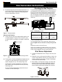
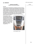
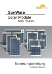
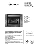
Gas Conversion Kit Gas Conversion Instructions For models: B34-DV ME34-DV-2 MD34-DV MD34-BV MD38-DV MD38-BV C38-DV Warning: If the information in these instructions is not followed exactly, a fire or explosion may result causing property damage, personal injury or loss of life. Do not store or use gasoline or other flammable vapors and liquids in the vicinity of this or any other appliance. What To Do If You Smell Gas: • Do not try to light any appliance. • Do not touch any electrical switch; do not use any phone in your building. • Immediately call your gas supplier from a neighbor's phone. Follow the gas supplier's instructions. • If you cannot reach your gas supplier, call the fire department. ME34-DV ME34-BV MD34-DV-2 ME38-DV ME38-BV C34-DV C42-DV Check local codes and read all instructions prior to conversion. Leave this manual with the owner. Installation and service must be performed by a qualified installer, service agency or the gas supplier. P/N XG0615 Page Gas Conversion Kit Table Of Contents General Information.................................................................. 2 Parts list..................................................................................... 2 Conversion Before you begin............................................................. 3 Front Burner.................................................................... 3 Rear Burner.................................................................... 3 Pilot Assembly................................................................. 3 Main Gas Control Regulator........................................... 4 Check the Gas Pressure................................................. 4 Adjusting the Pilot Burner............................................... 4 General Information This gas conversion kit contains the necessary components for field conversion of an approved Montigo fireplace from Natural Gas (NG) to Liquid Propane (LP).This kit is approved for use with the following Direct Vent (top and rear vent versions) and B-Vent models: B34-DV ME38-DV ME38-BV ME34-DV ME34-DV-2 MD38-DV MD38-BV MD34-DV-2 MD34-DV ME34-BV C34-DV C38-DV C42-DV The conversion of this appliance must conform with local codes or, in the absence of local codes, with the American National Fuel Gas WARNING! Operation.................................................................................... 5 This conversion kit shall be installed by a qualified service agency in accordance with the manufacturer's instructions and all applicable codes and requirements of the authority having jurisdiction. If the information in these instructions is not followed exactly, a fire, explosion or production of carbon monoxide may result causing property damage, personal injury or loss of life. The qualified service agency is responsible for the proper installation of this kit. The installation is not proper and complete until the operation of the converted appliance is checked as specified in the manufacturer's instructions supplied with this kit. Parts List Page Quantity Description 1 Pilot orifice 1 Rear burner orifice 1 Front burner orifice 1 Rear burner 1 Front burner 1 Hi/Lo Regulator Kit for the gas control valve 1 Label for rating plate indicating conversion 1 Label for gas control valve indicating conversion P/N XG0615 Gas Conversion Kit Gas Conversion Instructions Conversion Rear Burner: CAUTION - Before you begin: 1. Shut off gas at the shut-off valve and disconnect the electrical supply (if used). 2. Remove the glass door as shown in the installation instructions and remove the logs. Flip down or remove the lower trims. Front Burner: 3. On the B34, ME34,MD34, and C34 models, remove the screw that secures the left end of the burner to the firebox. On the ME38, MD38, C38, and C42 models, remove the clip which holds the left end of the burner tube on the burner bracket, then lift the burner out of the bracket. See Figure 1. 6. Remove the screw that secures the left end of the burner to the firebox. Slide the rear burner tube off the orifice on the right-hand side. Move the burner carefully, because the pilot assembly is attached to the back of the burner tube. Unscrew the old orifice from the orifice holder, and replace it with the new orifice from this kit marked 'R' (rear). Tighten the new orifice until it is snug to prevent any leaks. Do not overtighten. Pilot Assembly: Power Pile Igniter Pilot Hood Thermocouple ME38, MD38, C38, C42 B34, ME34, MD34, C34 Burner Tube Orifice 1 2 Orifice Holder Pilot Orifice Lock Nut Orifice Burner Tube Pilot Tube 1 2 Orifice Holder Lock Nut Figure 1. Removing the burner tube and replacing the orifice. 4. Carefully slide the front burner tube off the orifice (located inside the right end of the burner). See Figure 1. Figure 3. The Pilot assembly. Unscrew the pilot tubing carefully to access the pilot orifice. 7. While you have the rear burner removed, carefully unscrew the pilot tubing and remove the pilot orifice. Replace it with the new orifice supplied with this kit. Re-attach and tighten the pilot tubing, taking care not to damage the tubing by overbending or pinching it. (See figure 3.) Replace the old orifice with the new orifice marked 'F' (front) from this kit. Tighten the new orifice until it is snug to prevent any leaks. Do not overtighten, as this will loosen the lock nut on the orifice holder. Refer to the green sheet included with this kit for orifice sizes. 5. Installl the new front burner (marked 'F' )which is supplied with this kit. Burner Tube Figure 4. Pilot orifices, showing identification markings. The pilot orifice has a small marking on the side to indicate its size and which gas it is for. Ensure that you install the correct orifice in the pilot assembly. (See figure 4.) Orifice Lock Nut Figure 2. Installing the new burner tubes. P/N XG0615 Page Gas Conversion Kit Gas Conversion Instructions Checking the Gas Pressure 8. Re-install the rear burner and ensure that the pilot burner is correctly positioned. The pilot hood should aligned with the burner tube as shown in Figure 5. Make any necessary adjustments before proceeding with the conversion. A To check the Inlet and Manifold gas pressures, a Water Column Pressure Gauge with 5/16" dia. tubing can be used. To test the Manifold Pressure, loosen the screw shown in Figure 7. Attach the gauge to the Manifold Pressure Test Connection and open the gas shut-off valve. The tubing must be tight in the connection to prevent gas leaks. Measure the Manifold Pressure and compare the value against the chart below. Power Generator Pilot Adjustment Screw A Wall Switch Inlet Pressure Manifold Pressure Test Connection Figure 7. Sit Nova 820 gas valve. Section AA Figure 5. Pilot burner location. Main Gas Control Regulator: Manifold Pressure (min.) 9. The SIT Hi/Lo gas control valve supplied with this appliance has a removable regulator. To replace it, remove the three screws as shown in Figure 6, and install the new regulator supplied with this kit. remove screws to replace regulator Inlet Pressure (min.- max.) Natural Gas Liquid Propane 3.5" W.C. 10" W.C. 5.5" - 14" W.C. 11" - 14" W.C. " W.C. = inches water column Turn off the fireplace and close the shutoff valve. Remove the test gauge. Re-tighten the test connection screw to prevent gas leakage. Repeat the procedure for the Inlet Pressure. If the pressure readings are not within the limits set out, contact the factory. If the pressure readings are correct, ensure that both test connection screws are tightened securely, to prevent a gas leak. Pilot Burner Adjustment 1. Locate the Pilot Adjustment Screw on the gas control valve. (See figure 7) Figure 6. Replacing the regulator on the Sit Nova 820 gas control valve. 10. The label (part no. XL0201) indicating that the fireplace has been converted for use with a different gas must be placed on the fireplace rating plate over top of the existing fuel type chart. The label (part no. XL0200) indicating who converted the appliance must be filled out and placed on the base pan, directly under the gas valve. Also place the label indicating that the control valve has been converted for use with a different gas. 2. Adjust pilot screw to provide properly sized flame as shown in figure 8). To increasethe flame, turn the screw counterclockwise. To decrease the flame, turn it clockwise. The flame should impinge on the thermocouple and thermopile. 3. After installing or servicing, leak test using a soap solution with main burner turned on. Coat pipe and tubing joints, gasket etc. with soap solution. Bubbles indicate leaks. Tighten any areas where the bubbles appear until the bubbling stops completely. Figure 8. Pilot Burner Page P/N XG0615 Gas Conversion Kit Operating Instructions For Your Safety - READ BEFORE LIGHTING: WARNING: If you do not follow these instructions exactly, a fire or explosion may result causing property damage, personal injury or loss of life. A. This appliance has a pilot. When lighting the pilot, follow these instructions exactly. B. BEFORE LIGHTING smell all around the appliance area for gas. Be sure to smell next to the floor because some gas is heavier than air and will settle on the floor. What To Do If You Smell Gas: Do not try to light any appliance. Do not touch any electrical switch; do not use any phone in your building. Immediately call your gas supplier from a neighbour's phone. Follow the gas supplier's instructions. If you cannot reach your gas supplier, call the Fire Department. C. Use only your hand to push in or turn the gas control knob. Never use tools. If the knob will not push in or turn by hand, don't try to repair it, call a qualified service technician. Force or attempt to repair may result in a fire or explosion. D. Do not use this appliance if any part has been under water. Immediately call a qualified service technician to inspect the appliance and to replace any part of the control system, and any gas control which has been under water. Lighting Instructions: 1. 2. 3. 4. STOP! Read the safety information above on this label. Flip down lower trims. Push in gas control knob and turn clockwise to "OFF." Wait five (5) minutes to clear out any gas. Smell for gas, including near the floor. If you then smell gas, STOP! Follow "B" in the safety information above on this label. If you don't smell gas, go to the next step. 5. Locate pilot burner (See illustration at right.) and follow steps below. 6. Turn knob on gas control counterclockwise to "PI- Gas Control Knob (Shown in "Pilot" postion.) NOTE: Knob cannot be turned from "PILOT" to "OFF" unless knob is pushed in slightly. Do not LOT." 7. Push in gas control knob completely and hold. Light with Piezo Igniter button. Continue to hold the control knob in for about (1) minute after the pilot is lit. Release the knob and it will pop back up. Pilot should remain lit. If it goes out repeat steps 3 through 8. If knob does not pop up when released. Stop and immediately call your service technician or gas supplier. If the pilot will not stay lit after several tries, turn the gas control knob to "OFF" and call your service technician or gas supplier. 8. Push in gas control knob and turn counterclockwise to "ON." 9. Flip up lower trim. 10.Turn on remote switch to ignite fire. To Turn Off Gas To Appliance: 1. Turn off remote switch. 2. Flip down lower trim. P/N XG0615 3. Push in gas control knob slightly and turn to "Off". Do not force. 4. Flip up lower trim. clockwise Page Gas Conversion Kit XG0615 Rev. 01 - 07/00 Page Canadian Heating Products Inc. Montigo Del Ray Corp. Langley, BC V4W 4A1 Ferndale, WA 98248 P/N XG0615