1
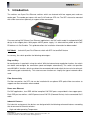
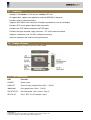
5 10/100TX + 1 100FX Industrial Switch w/POE Model: 900-7405P1GC16 SIGNAMAX a.s. Seat: Palackeho trida 38, 612 00 Brno, CZ l Office: Vlarska 22, 627 00 Brno, CZ T:+420 533 338 854 l F:+420 533 338 883 l www.signamax.eu The information contained in this document is subject to change without prior notice. Copyright (C). All Rights Reserved. TRADEMARKS Ethernet is a registered trademark of Xerox Corp. WARNING: This equipment has been tested and found to comply with the limits for a Class A digital device, pursuant to Part 15 of the FCC Rules. These limits are designed to provide reasonable protection against harmful interference when the equipment is operated in a commercial environment. This equipment generates, uses, and can radiate radio frequency energy and if not installed and used in accordance with the instruction manual may cause harmful interference in which case the user will be required to correct the interference at his own expense. NOTICE: (1) The changes or modifications not expressively approved by the party responsible for compliance could void the user's authority to operate the equipment. (2) Shielded interface cables and AC power cord, if any, must be used in order to comply with the emission limits. CISPR A COMPLIANCE: This device complies with EMC directive of the European Community and meets or exceeds the following technical standard. EN 55022 - Limits and Methods of Measurement of Radio Interference Characteristics of Information Technology Equipment. This device complies with CISPR Class A. CE NOTICE Marking by the symbol indicates compliance of this equipment to the EMC directive of the European Community. Such marking is indicative that this equipment meets or exceeds the following technical standards: EN 55022: Limits and Methods of Measurement of Radio Interference characteristics of Information Technology Equipment. EN 50082/1:Generic Immunity Standard -Part 1: Domestic Commercial and Light Industry. EN 60555-2: Disturbances in supply systems caused by household appliances and similar electrical equipment Part 2: Harmonics. SIGNAMAX a.s. Seat: Palackeho trida 38, 612 00 Brno, CZ l Office: Vlarska 22, 627 00 Brno, CZ T:+420 533 338 854 l F:+420 533 338 883 l www.signamax.eu Table of Contents 1. Introduction ........................................................................................................................... 5 1.1 Features............................................................................................................... 6 1.2 Product Panels..................................................................................................... 6 1.3 LED Indicators...................................................................................................... 6 1.4 Specifications ....................................................................................................... 7 2. Installation ............................................................................................................................. 9 2.1 Unpacking ............................................................................................................ 9 2.2 Safety Cautions .................................................................................................... 9 2.3 Mounting the Switch on a Wall ................................................................................ 9 2.4 Din-Rail Mounting ................................................................................................. 10 2.5 Panel Mounting..................................................................................................... 11 2.6 Applying Power ..................................................................................................... 11 3. Making Connections........................................................................................................... 13 3.1 Making UTP Connections................................................................................... 13 3.2 Making Fiber Connection.................................................................................... 13 3.3 Making PoE Connections ................................................................................... 14 3.4 LED Indication.................................................................................................... 15 4. Applications ........................................................................................................................ 16 4.1 Applications with Basic Switch Model ................................................................. 16 4.2 Applications with PoE Switch Model ................................................................... 17 SIGNAMAX a.s. Seat: Palackeho trida 38, 612 00 Brno, CZ l Office: Vlarska 22, 627 00 Brno, CZ T:+420 533 338 854 l F:+420 533 338 883 l www.signamax.eu 1. Introduction The switches are 5-port Fast Ethernet switches which are featured with four copper ports and one combo port. The combo port comes with one RJ-45 and one SFP slot. The SFP slot can be mounted with a fiber transceiver optionally to support a fiber connection. For more coming PoE (Power Over Ethernet) applications, the PoE switch model is equipped with PoE design in four copper ports. With proper 48VDC power supply, it is able to deliver power to four PoE PD devices via Cat.5 cables. This guide describes the installation information for below model: PoE Model Industrial 5-port Fast Ethernet switch with SFP slot and PoE feature In summary, the switch provides the following advantages: Plug and Play No configuration is required in using the switch. With the featured auto-negotiation function, the switch can detect and configure the connection speed and duplex automatically. The switch also provides auto MDI/MDI-X function, which can detect the connected cable and switch the transmission wire pair and receiving pair automatically. This auto-crossover function can simplify the type of network cables used. Fiber Connectivity For fiber connection, the SFP slot can be installed with an optional SFP optical fiber transceiver to support one fiber connection when needed. Power over Ethernet For PoE applications, four IEEE 802.3af-compliant PoE PSE ports are provided in four copper ports. Each PSE port can deliver +48VDC power to one PoE PD (Powered Device) via the connected Cat.5 cable. Industrial Features For industrial environment, the devices are designed with the following enhanced features exceeding that of commercial Ethernet switches: • High and wide operating Temperature SIGNAMAX a.s. Seat: Palackeho trida 38, 612 00 Brno, CZ l Office: Vlarska 22, 627 00 Brno, CZ T:+420 533 338 854 l F:+420 533 338 883 l www.signamax.eu • Power input interface: Industrial screw terminal block and DC power jack for external commercial power adapter as option • Screw panel and DIN rail mounting support for industrial enclosure • Industrial-rated Emission and Immunity performance SIGNAMAX a.s. Seat: Palackeho trida 38, 612 00 Brno, CZ l Office: Vlarska 22, 627 00 Brno, CZ T:+420 533 338 854 l F:+420 533 338 883 l www.signamax.eu 1.1 Features Provides 5 10/100Mbps RJ-45 and one 100Mbps SFP slot All copper ports support auto-negotiation and auto-MDI/MDI-X detection Provides full wire speed forwarding Supports IEEE 802.3x flow control for full-duplex and backpressure for half-duplex Provides SFP slot for optional optical fiber connection Provides four IEEE 802.3af-compliant PoE PSE ports Provides two types of power supply interfaces - DC Jack and terminal block Supports stand-alone, wall, Din-Rail, and panel mounting Industrial-rated emission and immunity performance 1.2 Product Panels The following figure illustrates the faces of the switch: 1.3 LED Indicators LED Function POWER Power status LINK/ACT Port link status and activities (Port 1 - Port 5) 100M/10M Port speed status (Port 1 - Port 5) PoE STATUS Port PoE power status (Port 2 - Port 5) SFP/RJ-45 Port 1 SFP / RJ-45 selection status SIGNAMAX a.s. Seat: Palackeho trida 38, 612 00 Brno, CZ l Office: Vlarska 22, 627 00 Brno, CZ T:+420 533 338 854 l F:+420 533 338 883 l www.signamax.eu 1.4 Specifications Copper Ports w/h PSE (P2-P5) Compliance IEEE 802.3 10Base-T, IEEE 802.3u 100Base-TX Connectors Shielded RJ-45 jacks Pin assignments Auto MDI/MDI-X detection Configuration Auto-negotiation Transmission rate 10Mbps, 100Mbps Duplex support Full/Half duplex Network cable Cat.5 UTP Power over Ethernet IEEE 802.3af-compliant PSE (function equipped in PoE Model only) Combo Port (P1) Compliance IEEE 802.3 10Base-T, IEEE 802.3u 100Base-TX/100Base-FX Interface Selection Fiber is selected if an SFP fiber transceiver is installed in SFP slot Copper Interface Connector Shielded RJ-45 jack Pin assignments Auto MDI/MDI-X detection Configuration Auto-negotiation or software control Transmission rate 10Mbps, 100Mbps Duplex support Full/Half duplex Network cable Cat.5 UTP Fiber Interface Connector SFP slot for optional SFP type fiber transceivers Configuration 100Mbps, Full duplex Far End Fault Support Enabled Network cables MMF 50/125 60/125, SMF 9/125 Eye safety IEC 825 compliant Switch Functions MAC Addresses Table 1K entries Forwarding & filtering Non-blocking, full wire speed Switching technology Store and forward Maximum packet length Flow control 1536 bytes IEEE 802.3x pause frame base for full duplex operation SIGNAMAX a.s. Seat: Palackeho trida 38, 612 00 Brno, CZ l Office: Vlarska 22, 627 00 Brno, CZ T:+420 533 338 854 l F:+420 533 338 883 l www.signamax.eu Back pressure for half duplex operation Broadcast Storm Protection design SIGNAMAX a.s. Seat: Palackeho trida 38, 612 00 Brno, CZ l Office: Vlarska 22, 627 00 Brno, CZ T:+420 533 338 854 l F:+420 533 338 883 l www.signamax.eu Power over Ethernet Function (PoE Model) PSE Pin 4,5 Positive of power voltage (Typical 48VDC) PSE Pin 7,8 Negative of power voltage (Typical 48VDC) Discovery PD resistance 15K ~ 33K PD Classification Class 0 ~ 4 Power delivery 15.4W max. (per port) Protection Under voltage protection Over voltage protection Over current detection DC IN Power Input Interfaces DC IN Jack ( -D 6.3mm / + D 2.0mm) DC IN Terminal Block (screw type) Operating Input Voltages +6 ~ 60VDC Power Consumption 3W max. @7.5V (No PoE output) PoE Function Operating input voltage: +43V ~ 54V (Typical 48V) DC IN Jack Interfaces Power jack -D 6.3mm / + D 2.0mm DC IN Terminal Block Pins: + / - / GND Mechanical Dimension (base) 144 x 104.5 x 26 mm Housing Enclosed metal with no fan Mounting Support Din-rail mounting, Panel mounting, Wall mounting, Desktop mounting Environmental Operating Temperature Typical -20oC ~ 70oC Storage Temperature -20oC ~ 85oC Relative Humidity 10% ~ 90% Electrical Approvals FCC Part 15 rule Class A CE EMC, CISPR22 Class A Safety IEC60950-1 / EN60950 SIGNAMAX a.s. Seat: Palackeho trida 38, 612 00 Brno, CZ l Office: Vlarska 22, 627 00 Brno, CZ T:+420 533 338 854 l F:+420 533 338 883 l www.signamax.eu 2. Installation 2.1 Unpacking The product package contains: • The switch unit • One product CD-ROM 2.2 Safety Cautions To reduce the risk of bodily injury, electrical shock, fire, and damage to the product, observe the following precautions. • Do not service any product except as explained in your system documentation. • Opening or removing covers may expose you to electrical shock. • Only a trained service technician should service components inside these compartments. • If any of the following conditions occur, unplug the product from the electrical outlet and replace the part or contact your trained service provider: - The power cable, extension cable, or plug is damaged. - An object has fallen into the product. - The product has been exposed to water. - The product has been dropped or damaged. - The product does not operate correctly when you follow the operating instructions. • Do not push any objects into the openings of your system. Doing so can cause fire or electric shock by shorting out interior components. • Operate the product only from the type of external power source indicated on the electrical ratings label. If you are not sure of the type of power source required, consult your service provider or local power company. 2.3 Mounting the Switch on a Wall The switch can be mounted on a desktop or shelf or a wall. Make sure that there is proper heat dissipation from and adequate ventilation around the device. Do not place heavy objects on the device. SIGNAMAX a.s. Seat: Palackeho trida 38, 612 00 Brno, CZ l Office: Vlarska 22, 627 00 Brno, CZ T:+420 533 338 854 l F:+420 533 338 883 l www.signamax.eu SIGNAMAX a.s. Seat: Palackeho trida 38, 612 00 Brno, CZ l Office: Vlarska 22, 627 00 Brno, CZ T:+420 533 338 854 l F:+420 533 338 883 l www.signamax.eu 2.4 Din-Rail Mounting The steps to mount the switch on a Din-rail are: One Din-rail mounting bracket is provided in the product package as shown below: Install the bracket on the bottom of the switch unit. Mount the device on a Din-rail. SIGNAMAX a.s. Seat: Palackeho trida 38, 612 00 Brno, CZ l Office: Vlarska 22, 627 00 Brno, CZ T:+420 533 338 854 l F:+420 533 338 883 l www.signamax.eu 2.5 Panel Mounting One optional panel mounting bracket is available for your purchase as shown below: Install the bracket on the bottom of the switch unit. The final dimension after panel bracket is installed is shown below: 2.6 Applying Power The switch provides two types of power interfaces, terminal block and DC power jack for receiving DC power input from external power supply system. SIGNAMAX a.s. Seat: Palackeho trida 38, 612 00 Brno, CZ l Office: Vlarska 22, 627 00 Brno, CZ T:+420 533 338 854 l F:+420 533 338 883 l www.signamax.eu Using Terminal Blocks Three terminal contacts are provided: Vdc Positive (+) terminal Vdc Negative (-) terminal Chassis ground * Working Vdc for general application: +6V ~ +60VDC * Working Vdc for PoE application : +43V ~ +54VDC (Typ. 48V) One 3P terminal plugs are provided together with the switch. The plug is shown below: Power wires : 24 ~ 12AWG (IEC 0.5~2.5mm2) Install the power source wires with the plug properly. Then, plug in the terminal block socket. Using DC Power Jack When an external power system is not available, the switch provides a DC jack to receive power from typical AC-DC power adapter alternatively. AC Power Adapters: Optional commercial rated adapters are available for purchasing. Non-PoE applications PoE applications Rated output DC7.5V 0.5A / 1A / 1.2A Rated input 100V ~ 240VAC, Output 48VDC / 24W (About 20-21W is reserved for PoE PDs connected.) Note: * Before you begin the installation, check the AC voltage of your area. The AC power adapter which is used to supply the DC power for the unit should have the AC voltage matching the commercial power voltage in your area. * For PoE applications, make sure the rated output power meets the required voltage and power consumption required by all connected PD devices. Refer to sec. 3.3 for more information. SIGNAMAX a.s. Seat: Palackeho trida 38, 612 00 Brno, CZ l Office: Vlarska 22, 627 00 Brno, CZ T:+420 533 338 854 l F:+420 533 338 883 l www.signamax.eu 3. Making Connections 3.1 Making UTP Connections The copper ports support the following connection types and distances: Network Cables 10BASE-T: 2-pair UTP Cat. 3,4,5 , EIA/TIA-568B 100-ohm 100BASE-TX: 2-pair / 4-pair UTP Cat. 5, EIA/TIA-568B 100-ohm Link distance: Up to 100 meters Auto MDI/MDI-X Function This function allows the port to auto-detect the twisted-pair signals and adapts itself to form a valid MDI to MDI-X connection with the remote connected device automatically. No matter a straight through cable or crossover cable is connected, the ports can sense the receiving pair automatically and configure itself to match the rule for MDI to MDI-X connection. It simplifies the cable installation. Auto-negotiation Function The ports are featured with auto-negotiation function and full capability to support connection to any Ethernet devices. The port performs a negotiation process for the speed and duplex configuration with the connected device automatically when each time a link is being established. If the connected device is also auto-negotiation capable, both devices will come out the best configuration after negotiation process. If the connected device is incapable in auto-negotiation, the switch will sense the speed and use half duplex for the connection. 3.2 Making Fiber Connection The SFP slot must be installed with an SFP fiber transceiver for making fiber connection. Your switch may come with an SFP transceiver pre-installed when it is shipped. To install an SFP fiber transceiver into the SFP slot, the steps are: 1. Turn off the power to the switch. 2. Insert the SFP fiber transceiver into the SFP slot. Normally, a bail is provided for every SFP transceiver. Hold the bail and make insertion. 3. Until the SFP transceiver is seated securely in the slot, place the bail in lock position. 4. Turn on the power to the switch. Connecting Fiber Cables LC connectors are commonly equipped on most SFP transceiver modules. Identify TX and RX connector before making cable connection. The following figure illustrates a connection example between two fiber ports: SIGNAMAX a.s. Seat: Palackeho trida 38, 612 00 Brno, CZ l Office: Vlarska 22, 627 00 Brno, CZ T:+420 533 338 854 l F:+420 533 338 883 l www.signamax.eu Make sure the Rx-to-Tx connection rule is followed on the both ends of the fiber cable. Network Cables Multimode (MMF) - 50/125, 62.5/125 Single mode (SMF) - 9/125 SIGNAMAX a.s. Seat: Palackeho trida 38, 612 00 Brno, CZ l Office: Vlarska 22, 627 00 Brno, CZ T:+420 533 338 854 l F:+420 533 338 883 l www.signamax.eu 3.3 Making PoE Connections This section describes how to make a connection between a PSE port and a PoE PD device. For the PoE switch model, Port 2, Port 3, Port 4 and Port 5 are equipped with PoE PSE function. The ports are enabled to deliver power together with network signal to a connected powered device via Cat.5 cable. To make a PoE connection, the following check points should be noted: 1. For safety reason, the connected PoE PD (Powered Device) must be a IEEE 802.3af-compliant device. Incompliant devices are not supported by the PoE switch model. 2. The Cat.5 cables used for the connections must be 4-pair cables. The power is sent over the spare pairs (4,5) (7,8) of the cable. The maximum distance supported is 100 meters. 3. The DC IN power voltage supplied to the switch must be within the following range to make PoE function working. DC IN voltage range for PoE applications : +43V ~ +54V 4. The DC IN power supplied to the switch must meet the following calculation: DC IN power = Sum of all connected PD power required + 3 watts The PSE ports are equipped with the following capabilities: 1. Detection for an IEEE 802.3af compliant PD. 2. No power is supplied to a device which is classified non-IEEE 802.3af complaint PD. 3. No power is supplied when no connection exists on the port. 4. The power is cut off immediately from powering condition when a disconnection occurs. 5. The power is cut off immediately from powering condition when overload occurs. 6. The power is cut off immediately from powering condition when overcurrent occurs. 7. The power is cut off immediately from powering condition when short circuit condition occurs. The figure below illustrates a connection example: SIGNAMAX a.s. Seat: Palackeho trida 38, 612 00 Brno, CZ l Office: Vlarska 22, 627 00 Brno, CZ T:+420 533 338 854 l F:+420 533 338 883 l www.signamax.eu 3.4 LED Indication LED Function POWER Power status State ON OFF LINK/ACT Port link status ON Interpretation The power is supplied to the switch. The power is not supplied to the switch. A port link is established. (No traffic) BLINK Port link is up and there is traffic. OFF 100M/10M Port speed status ON OFF PoE STATUS Port PoE power ON OFF SFP/RJ-45 Port1 status ON OFF Port link is down. Speed 100M is selected. Speed 10M is selected. PoE power is delivered on the port. PoE power is shut down. SFP is used on Port 1. RJ-45 is used on Port 1. SIGNAMAX a.s. Seat: Palackeho trida 38, 612 00 Brno, CZ l Office: Vlarska 22, 627 00 Brno, CZ T:+420 533 338 854 l F:+420 533 338 883 l www.signamax.eu 4. Applications 4.1 Applications with Basic Switch Model The following figure illustrates a basic switch model connects five computers via Cat.5 cables. The following figure illustrates a basic switch model connects four computers via Cat.5 cables and uplink to a fiber backbone network. SIGNAMAX a.s. Seat: Palackeho trida 38, 612 00 Brno, CZ l Office: Vlarska 22, 627 00 Brno, CZ T:+420 533 338 854 l F:+420 533 338 883 l www.signamax.eu 4.2 Applications with PoE Switch Model The figure below illustrates a PoE switch connects four PoE IP cameras via Cat.5 cables and uplinks to a fiber backbone: The figure below illustrates a PoE switch connects four PoE WLAN access points via Cat.5 cables and uplinks to a backbone: SIGNAMAX a.s. Seat: Palackeho trida 38, 612 00 Brno, CZ l Office: Vlarska 22, 627 00 Brno, CZ T:+420 533 338 854 l F:+420 533 338 883 l www.signamax.eu The figure below illustrates a PoE switch powered by a 48V DC power adapter connects four PoE media converters via Cat.5 cables and uplinks to a fiber backbone: SIGNAMAX a.s. Seat: Palackeho trida 38, 612 00 Brno, CZ l Office: Vlarska 22, 627 00 Brno, CZ T:+420 533 338 854 l F:+420 533 338 883 l www.signamax.eu