1
Service Manual
Washer extractor
W555H
Type W.55.H
Service manual in original language
438 9038-40/EN
2012.02.24
Contents
Contents
1 Safety Precautions ............................................................................................................. 5
2 Technical data .................................................................................................................... 6
2.1 Drawing ...................................................................................................................... 6
2.2 Technical data............................................................................................................. 7
2.3 Connections................................................................................................................ 7
2.4 Sound levels ............................................................................................................... 7
3 Machine presentation......................................................................................................... 8
4 Function check ................................................................................................................... 9
5 Door and door lock............................................................................................................. 10
5.1 Door lock .................................................................................................................... 10
6 Motor and motor control ..................................................................................................... 13
6.1 Motor control unit........................................................................................................ 13
6.2 Replacement of motor ................................................................................................ 14
7 Heating............................................................................................................................... 16
7.1 Replacement of heating element................................................................................ 16
8 Drum .................................................................................................................................. 18
8.1 Replacement of drum ................................................................................................. 18
8.2 Replacement of the belt.............................................................................................. 23
9 Drain................................................................................................................................... 24
9.1 Drain valve.................................................................................................................. 24
9.2 Drain pump ................................................................................................................. 27
10 Detergent container.......................................................................................................... 28
10.1 Replacement of detergent container ........................................................................ 29
10.2 Replacement of siphon............................................................................................. 29
10.3 Replacement of reed switch ..................................................................................... 30
11 Control panel .................................................................................................................... 31
11.1 Program unit ............................................................................................................. 31
11.1.1 Description ........................................................................................................ 31
11.1.2 Connections ...................................................................................................... 32
11.1.3 Replacement of program unit............................................................................ 33
11.2 Control knob ............................................................................................................. 37
11.2.1 Replacement of control knob ............................................................................ 37
12 I/O modules...................................................................................................................... 40
12.1 General..................................................................................................................... 40
12.2 Replacement of I/O module...................................................................................... 41
12.3 External connections to I/O module type 2............................................................... 45
12.4 Circuit diagram of function options for I/O module type 2......................................... 46
12.4.1 External coin meter/Central payment (2A)........................................................ 46
12.4.2 Central payment (2B)........................................................................................ 47
12.4.3 Central payment (2C)........................................................................................ 48
12.4.4 Outputs for detergent signals and inputs for pause signals and "empty"
signal, price reduction (2D)................................................................................ 49
12.4.5 Outputs for detergent signals and inputs for pause signals and "empty"
signal (2E).......................................................................................................... 50
12.4.6 Central booking/payment (2F) .......................................................................... 51
12.4.7 Machines with I/O module type 3...................................................................... 52
13 Troubleshooting................................................................................................................ 53
Contents
13.1 General..................................................................................................................... 53
13.2 Error code................................................................................................................. 54
13.3 Description of error codes and causes ..................................................................... 56
MAIN COMMON .......................................................................................................... 56
MAIN WASHER ........................................................................................................... 57
DRUM MOTOR COMMON .......................................................................................... 61
DRUM MOTOR MCU................................................................................................... 62
INTERNAL COM.......................................................................................................... 67
INTERNAL COM. I/O ................................................................................................... 68
INTERNAL COM. I/O TYPE 6...................................................................................... 70
EXTERNAL COM. PAYMENT...................................................................................... 71
EXTERNAL COM. CMIS.............................................................................................. 72
14 Maintenance..................................................................................................................... 73
14.1 Inspect the interior of the machine ........................................................................... 73
The manufacturer reserves the right to make changes to design and component specifications.
Safety Precautions
1 Safety Precautions
The machine is only intended for water-wash use.
Do not allow minors to use the machine.
Do not hose down the machine with water.
The machine's door lock must under no circumstances be bypassed.
If the machine develops a fault, this must be reported to the person in charge as soon as possible. This is
important both for your safety and that of others.
The machine is not intended to be used by people (including minors) with reduced physical or mental
capacity or lack of experience and knowledge. Such people must be instructed in the use of the machine
by a person who has responsibility for their safety. Minors must be supervised to ensure that they do not
play with the machine.
DO NOT MODIFY THIS APPLIANCE.
All external equipment which is connected to the machine must be CE/EMC-approved and connected using
an approved shielded cable.
In order to prevent damage to the electronics (and other parts) that may occur as the result of condensation,
the machine should be placed in room temperature for 24 hours before being used for the first time.
Servicing shall be carried out only by authorized personnel.
5
Technical data
6
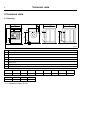
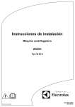
2 Technical data
2.1 Drawing
G
A
B
B
F
3
1
8
H
H
4
2
5
C
K
E
6
6
D
7
I
J
fig.6733A
1
Operating panel
2
Door opening, ⌀ 255 mm
3
Detergent container
4
Cold water
5
Hot water
6
Drain valve
7
Drain pump
8
Electrical connection
mm
mm
A
B
C
D
E
F
G
H
595
680
850/875*
305
660
80
195
60
I
J
K
90
80
650
* C = Adjustable height, 25 mm.
Technical data
7
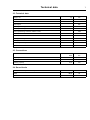
2.2 Technical data
Weight, net
kg
102
litres
53
Drum diameter
mm
452
Drum depth
mm
332
Drum speed during wash
rpm
35/54
Drum speed during extraction
rpm
1450
Drum speed during extraction, Marine model
rpm
1300
Drum volume
G-factor, max.
530
G-factor, max. Marine model
425
Heating: Electricity
kW
4.4
x
Heating: Hot water
Frequency of the dynamic force
Hz
24.2
Floor load at max extraction
kN
1.2±0.3
2.3 Connections
Water valves
DN
BSP
20
3/4”
Capacity at 300 kPa
l/min
17
⌀ outer mm
50
l/min
160
Wash
dB(A)
59
Extraction
dB(A)
72
Drain valve
Draining capacity
2.4 Sound levels
Sound power level (IEC 60704-2-4)
Machine presentation
8
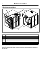
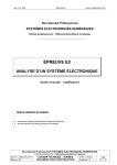
3 Machine presentation
7
6
5
1
4
2
3
8
fig.7608
①
1
Door
2
Motor
3
Heating unit
4
Drum
5
Detergent container
6
Control panel with program unit
7
I/O modules
8
Drain / Drain pump
After a repair has been made
Whenever a repair has been made, a function check must be performed before the machine can
be used again.
Function check
4 Function check
May only be carried out by qualified personnel.
A function check must be made when the installation is finished and before the machine can be
ready to be used.
Open the manual water valves.
Add detergent in the compartment for main wash and start a program.
• Check that the drum rotates normally and that there are no unusual noises.
• Check that there are no leaks in water supply/drain connections.
• Check that water passes through the detergent container.
• Check that the door cannot be opened during a program.
Ready to use
If all tests are OK the machine is now ready to be used.
If some of the tests failed, or deficiencies or errors are detected, please contact your local service
organisation or dealer.
9
10
Door and door lock
5 Door and door lock
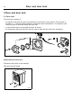
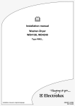
5.1 Door lock
The door lock consists of:
• An actuator that locks the door lock and also has one built-in micro switch. The actuator is
bi-stable, i.e., it has two stable positions: locked door and unlocked door. The actuator must
receive a pulse to lock and unlock the door lock.
• A micro switch that is closed when the door is closed.
• An emergency opening button that can be used to open the door lock in an emergency .
fig.500236
②
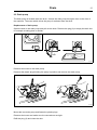
Replacement of door lock
Disconnect the power to the machine.
Demount the front panel.
fig.6215B
③
Door and door lock
11
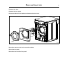
Demount the door.
Demount the trim panel.
Disconnect the door lock cables and demount the door lock.
fig.7578
④
Mount the new door lock and connect the cables.
Mount the trim panel.
Mount the door and the front panel.
12
Door and door lock
Emergency opening of door lock
The door can be opened by pressing the emergency opening button.
To access the emergency opening button, remove the front panel. The emergency opening button
can be reached between the left side panel and the trim panel. If not accessible, remove also
the trim panel.
fig.7577
⑤
Motor and motor control
13
6 Motor and motor control
Take care when measuring the motor control system since all components have a potential difference of
approximately 300V in relation to protective earth and neutral.The components will contain dangerous
voltages when the green LED on the motor control board is on. The motor control system will remain live for
30-60 seconds after cutting the power to the machine and the motor has stopped running.
6.1 Motor control unit
The motor control unit communicates with the program control unit board via a serial (input/output)
interface. With the aid of the motor control unit the program control unit can control not only the
speed of the motor at any given point, but also the acceleration or deceleration rate at which the
motor is to achieve the speed required. The motor control unit constantly feeds information on
current status (both normal status and on any abnormalities arising) back to the program control
unit board.
The motor control unit can also supply data on the different torque and effect of the motor at
constant speed when accelerating and decelaration. These data are used both for calculating the
weight of the load and for detecting any unbalance.
The voltage on the motor control circuit has a potential difference of approx. 300 V in relation to incoming
neutral and earth. Because of this, be careful when measuring. Use unearthed oscilloscopes. If the motor
control unit has a green LED, this will remain lit for as long as there are hazardous voltages present in
components.
14
Motor and motor control
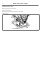
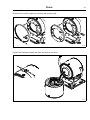
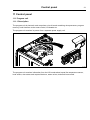
6.2 Replacement of motor
Disconnect the power to the machine.
Demount the rear panel.
Disconnect the motor cable and unscrew the earth screw.
Remove the belt.
fig.7580
⑥
Motor and motor control
15
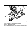
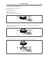
Demount the motor. Start with the bolt to the right and then the bolt to the left.
fig.7581
⑦
Mount the new motor. Start with the bolt to left and then the bolt to the right.
Fasten the belt. Make sure the belt is in position.
Check the belt tension with a frequency meter or similar. The frequency shall be 70 Hz ± 5. Adjust if
necessary with the right screw in the slotted hole.
Connect the motor cable and refit the earth screw.
Mount the rear panel.
Heating
16
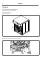
7 Heating
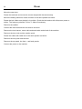
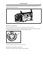
7.1 Replacement of heating element
Disconnect the power to the machine.
Demount the rear panel.
Remove the belt (A).
A
fig.7579
⑧
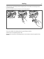
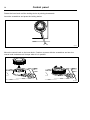
Disconnect the connectors to the heating element.
fig.7583
⑨
Heating
17
Loosen the bolt to the heating element and gently push on the middle of the heating element
to release the flange.
Remove the heating element and insert the new heating element.
fig.7584
⑩
Push on the middle of the heating element to get the flange in position.
Fasten the bolt. Use tightening torque 6 Nm.
Reconnect the connectors to the heating element, use the electric schematic supplied with the
machine.
18
Drum
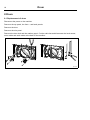
8 Drum
8.1 Replacement of drum
Disconnect the power to the machine.
Demount the top panel, the front— and back panels.
Demount the door.
Demount the trim panel.
Demount the door lock and the rotation guard. Cut the cable ties and disconnect the level sensor,
motor cable and earth cable at the back of the machine.
fig.7572A
⑪
Drum
19
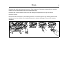
Demount the drain and hoses to the drum. Drain and type of hoses are depending on machine
model, for more information refer to the spare parts list).
Demount the air hose and the hose from the detergent compartment on top of the drum.
Remove the belt.
Disconnect the connectors to the heating elements. Loosen the bolt to the heating element and
gently push on the middle of the heating element to release the flange. Remove all heating
elements.
fig.7591
⑫
20
Drum
Disconnect the inlet hose and the vent hose from the drum.
Unscrew the screws to the side panels and lift of the cabinet to release the drum package.
fig.7573
⑬
Drum
21
Demount the counter weight by loosening the tension strap.
fig.7574
⑭
Loosen the tensioner holding the drum and remove the drum.
fig.7575
⑮
22
Drum
Mount the new drum.
Fasten the tensioner and mount the counter weight with the tension strap.
Mount the heating elements, hoses and drain in the same position as before.
Fasten the belt. Make sure the belt is in position. Check the belt tension with a frequency meter or
similar. The frequency shall be 70 Hz ± 5. Adjust if necessary.
Remount the cabinet.
Connect the inlet hose and the vent hose to the drum.
Remount the level sensor, motor cable and earth cable at the back of the machine.
Remount the door lock and the rotation guard.
Fasten the cables with cable ties in the same position as before.
Remount the trim panel and the door.
Remount the top panel, the front— and back panels.
Connect the power to the machine.
Drum
23
8.2 Replacement of the belt
Disconnect the power to the machine.
Demount the back panel.
Remove the belt (A) and put the new belt in position. Check the belt tension with a frequency
meter or similar. The frequency shall be 70 Hz ± 5. Adjust if necessary with the right screw in
the slotted hole.
A
fig.7579
⑯
Remount the back panel.
Connect the power to the machine.
Drain
24
9 Drain
9.1 Drain valve
The water pressure in the cold water intake is used for closing the drain valve. There is a hose (1)
connected between the water intake and the control valve (2). When the control valve is activated
it opens and lets water into the supply line (3) which is connected to the drain valve. The water
presses up a rubber membrane (4) and a plunger (5) with a pressure plate (6) which closes the
valve’s rubber membrane (7).
When the control valve shuts off water pressure to the drain valve the springs (8) pull back the
plunger. The return water passes the control valve and runs out into the drain via the return hose (9).
9
3
2
1
7
6
8
5
4
fig.7500
⑰
Drain
25
Replacement of drain valve
Disconnect the power to the machine.
Demount the front panel.
fig.6215B
⑱
Demount the door.
Demount the trim panel.
Remove the hose from the valve’s nipple for water supply (A).
Remove the nut but leave the bolt (B) in place, securing the drain valve to the right-hand side of
the saddle. Remove the bolts (C) securing the drain valve on the left-hand side of the saddle. Pull
down the left side of the drain valve a little and then lift the drain valve off from the right-hand bolt.
Demount the drain valve from the hose (D).
C
B
D
A
fig.2407
⑲
26
Drain
Mount the new drain valve.
Mount the drain valve onto the right-hand bolt (B) on the saddle. Mount the bolts (C) on the
left-hand side of the saddle. Tighten the bolt (B).
Mount the hose for water supply (A).
Mount the hose from the drum (D) on the drain valve. The rubber edge on the hose shall be pulled
down over the valve cover. Check that the hose edge snaps into place over the lower edge of
the cover.
Mount the trim panel, the door and the front panel.
Drain
27
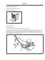
9.2 Drain pump
The drain pump is located under the drum. Access the drain pump through a door on the front of
the machine. The motor which drives the pump is activated from the timer.
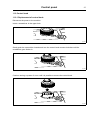
Replacement of drain pump
Open the door to the drain pump and pull out the hose. Remove the plug (A) to empty the drain into
for example a baking plate or similar.
A
fig.7388
⑳
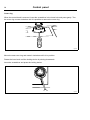
Demount the hoses to the drain pump.
Demount the plastic plugs holding the pump in position and remove the drain pump.
fig.7498
21
Mount the new drain pump and fasten the plastic plugs.
Remount the hoses and make sure the connections are tight.
Refit the plug (A) and close the door.
28
Detergent container
10 Detergent container
Water connections into the detergent container are fitted with dispersers which mix the detergent
thoroughly with water and flush the compartments clean. From the bottom of the detergent
container the water is flushed down into the drum.
fig.500234
22
Detergent container
29
10.1 Replacement of detergent container
Remove the detergent container from the machine and replace with the new one.
fig.7212B
23
10.2 Replacement of siphon
Remove the detergent container from the machine and remove the siphon to be replaced. Mount
the new siphon.
A
fig.7212C
24
30
Detergent container
10.3 Replacement of reed switch
Disconnect the power to the machine.
Demount the top panel.
Disconnect the cable from the program unit.
Remove the reed switch by pulling it out a bit and down from its position.
Mount the new reed switch and make sure it is in position. Connect the cable in the same position
as before.
1
2
fig.7605
25
Control panel
31
11 Control panel
11.1 Program unit
11.1.1 Description
The program unit is electronic and comprises a circuit board containing microprocessor, program
memory, serial interface to the motor control, I/O-boards etc.
The program unit receives its power from a separate power supply unit.
fig.7582
26
The program unit receives information from the I/O boards about inputs like temperature sensor,
level sensor, door status and outputs like drum, water valves, drain and heat control.
32
Control panel
11.1.2 Connections
The program unit board has the following connections:
Function
M-COM
Communication, motor control
D-BUS
Databus
D-BUS
Databus
TACHO
Tachometer
COIN
Coin meter (coin 1, coin 2, blocking)
EMERG / INP 1
Input, reed switch detergent box
FREE / INP 2
Free program (key switch) / Input
RS 232
Serial communication
ENC
Control knob (pulses)
USB TYPE B
Connection for software / service download
PIN CONNECTOR
Panel sign connector
LEVEL
Level control
DO
Digital output
OUTP
Output
DOOR IN
Door lock
P-BUS
Power bus
TEMP
Temp sensor
IN
Board connector
fig.W00284
27
Control panel
33
11.1.3 Replacement of program unit
Disconnect the power to the machine.
Demount the top panel.
Demount the control knob
Insert a screwdriver in the upper hole.
fig.7491
28
Gently push the screwdriver inwards and turn the control knob counter-clockwise until the
screwdriver goes further in.
fig.7492
29
Continue turning a quarter of a turn until it is possible to remove the control knob.
fig.7493
30
34
Control panel
Demount the cover ring
When the control knob is removed, insert the screwdriver in the lower hole and press gently. Turn
the cover ring counter-clockwise until it is possible to remove the cover ring.
fig.7490
31
Demount the program unit
Demount the cover to the CPU and disconnect the cables.
Loosen the screws holding the program unit onto the panel and demount the program unit.
fig.7606
32
Control panel
35
Demount the control knob unit from the program unit by unscrewing the screw a bit (4–5 mm)
until the control knob unit loosens.
fig.7640
33
Mount the new program unit
Start by mounting the control knob unit on the program unit. Fasten the screw.
Mount the program unit with the CPU part. Mount the program unit on the control panel and make
sure that the guide pins are in position. Fasten the screws to the panel.
A
fig.7511
34
Connect the cables and remount the cover to the CPU.
Mount the cover ring and the control knob
Mount the cover ring and rotate it clockwise until it is in position.
36
Control panel
Rotate the inner knob until the locking device is pointing downwards.
Insert the screwdriver and press the locking device.
fig.7494
35
Mount the control knob on the inner knob. Continue to press with the screwdriver and turn the
control knob clockwise until it stops when it is in position.
fig.7495A
36
Control panel
37
11.2 Control knob
11.2.1 Replacement of control knob
Disconnect the power to the machine.
Insert a screwdriver in the upper hole.
fig.7491
37
Gently push the screwdriver inwards and turn the control knob counter-clockwise until the
screwdriver goes further in.
fig.7492
38
Continue turning a quarter of a turn until it is possible to remove the control knob.
fig.7493
39
38
Control panel
Cover ring
When the control knob is removed, insert the screwdriver in the lower hole and press gently. Turn
the cover ring counter-clockwise until it is possible to remove the cover ring.
fig.7490
40
Mount the new cover ring and rotate it clockwise until it is in position.
Rotate the inner knob until the locking device is pointing downwards.
Insert the screwdriver and press the locking device.
fig.7494
41
Control panel
39
Mount the new control knob on the inner knob. Continue to press with the screwdriver and turn
the control knob clockwise until it stops when it is in position.
fig.7495A
42
40
I/O modules
12 I/O modules
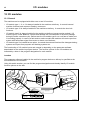
12.1 General
The machine can be equipped with either one or two I/O modules:
• I/O module type 1, 11 or 3 is always installed in the machine at delivery. It controls internal
machine functions and outputs to heating, motors etc.
• I/O module type 10 is always installed in the machine at delivery. It controls the door lock
functions.
• I/O module type 6 is always installed in the machine at delivery (except marine models). I/O
module type 6, Power Balance, controls and handles the out-of-balance of the drum package
during the entire extraction cycle. Before start the I/O module type 6 run a self test to make sure
it is working properly. In case of a fault and on marine models the machine will use the previous
system with tachometer signal from motor to detect out-of-balance.
• I/O module type 2 is installed as an option. It controls the external functions like detergent dosing
systems and inputs from payment and booking systems etc.
The functionality of I/O module inputs and outputs is depending on the parameter software
downloaded to the machine’s program device. The function options for the I/O modules are
indicated by a letter in the program designation for each module.
Location
The parameter software installed in the machine’s program device on delivery is specified at the
front and back of the machine.
Using this article number, you can find the program designation and thereby identify I/O module
function options on the web.
fig.W00282
43
I/O modules
41
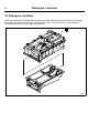
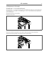
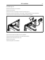
12.2 Replacement of I/O module
I/O module type 1, 11 or 3 and I/O module type 2
I/O module type 1, 11 or 3 and I/O module type 2 are installed in the same way. If the machine has
I/O module type 2, it is located on I/O module type 1, 11 or 3. The illustration shows replacement
of I/O module type 1.
Disconnect the power to the machine.
Demount the top panel.
fig.7609
44
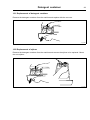
Remove the electrical connections on the module. (Note the position of the connections).
Remove the module by pulling it out towards the front of the machine.
fig.7610
45
I/O modules
42
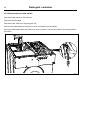
Insert the new module and make sure it is in position.
Connect the electrical connections in the same way as before.
If both I/O module type 1, 11 or 3 and I/O module type 2 is to be replaced it is recommended to fit
the modules together before mounting in the machine.
1
2
3
fig.7611
46
Remount the top panel.
Connect the power to the machine.
I/O modules
43
I/O module type 10
Disconnect the power to the machine.
Demount the top panel.
Remove the cover to the program unit and I/O module type 10.
Remove the electrical connections on the module. (Note the position of the connections).
Loosen the screw a bit and remove the I/O module by lifting it upwards.
fig.7607
47
Insert the new module and make sure it is in position.
Connect the electrical connections in the same way as before.
Fasten the screw and remount the cover.
Remount the top panel.
Connect the power to the machine.
I/O modules
44
I/O module type 6
Disconnect the power to the machine.
Demount the front panel.
Demount the door.
Demount the trim panel.
Disconnect the cable and demount I/O module type 6.
fig.500266
48
Mount the new module and make sure it is in position.
Connect the cable.
Mount the trim panel, the door and the front panel..
Connect the power to the machine.
I/O modules
45
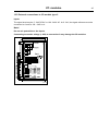
12.3 External connections to I/O module type 2
Inputs
The signal level may be 5 - 24V DC/AC or 100 - 240V AC. At 5 - 24V, the signal reference must be
connected to 3 and at 100 - 240V to 4.
Note!
Do not mix potentials on the inputs.
Connecting excessive voltage (> 24V) to connection 3 may damage the I/O modules.
1
2
3
4
5
6
7
8
9
10
11
12
13
14
15
16
17
18
19
fig.6236
49
46
I/O modules
12.4 Circuit diagram of function options for I/O module type 2
12.4.1 External coin meter/Central payment (2A)
The signal received from external coin meters must be a pulse.
In order to program/set prices, the signal initiating the price programming procedure must be
active (high).
fig.6606A
50
I/O modules
47
12.4.2 Central payment (2B)
To start the machine from a central payment system, the payment system must transmit a start
pulse to the machine. The start pulse can be either 230V or 24V. In order to receive a feedback
signal once the machine has started, 230V or 24V must be connected to connection 19. The
feedback signal on connection 18 remains active (high) during the entire program.
fig.6316A
51
48
I/O modules
12.4.3 Central payment (2C)
The central payment or booking system shall transmit an active (high) signal to the machine once
permission has been granted to start the machine. The signal must remain active (high) until the
machine starts. A feedback signal will be present on connection 18 and remain active (high) whilst
the machine door is closed but the program has not started. The feedback signal is powered
by 230V or 24V from connection 19.
fig.6313A
52
I/O modules
49
12.4.4 Outputs for detergent signals and inputs for pause signals and "empty"
signal, price reduction (2D)
The figure shows standard function addressing for machines with the coin program package.
By maintaining an active (high) signal on connection 5 ("Price red"), the price of the program can
be reduced. This function has a number of uses, including providing reductions during a specific
period of the day. Whilst the signal remains active (high), the price of the program is reduced by the
percentage entered in the price programming menu.
fig.6314A
53
50
I/O modules
12.4.5 Outputs for detergent signals and inputs for pause signals and "empty" signal
(2E)
Heating pause: By connecting a signal to connection 6, you can pause operation of the machine
whilst it heats up. The machine will pause for as long as the pause signal remains active (high).
fig.6315A
54
I/O modules
51
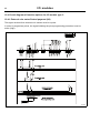
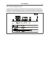
12.4.6 Central booking/payment (2F)
The central payment or booking system shall transmit an active (high) signal to the machine once
permission has been granted to start the machine. The signal must remain active (high) until the
machine starts. A feedback signal will be present on connection 18 and remain active (high) whilst
the program is running. The feedback signal is powered by 230V from connection 19 or external 24V.
F
3
5
6
1
2
1
2
3
5
RE101
Output 6 NO
Output 6 NC
RE102
RE103
RE104
4
Output 5
Output 4
RE105
Output 3
Output 2
Output 1
Input 4
Input 3
4
6
Con 107
1
2
Con 115
2
Con 109
1
Input 2
Input 1
RE106
Con 110
Con 108
2
Com.
Com.
Con 111
1
+5V
2
Function I/O:s
PTD5
Type of I/O card
3
Start permitted
Central booking / payment
EBS / PCB / Camping
230V
Start permitted
Central booking / payment
EBS / PCB / Camping
24V
0V
Program run NC
Program run NO
Liquid det. sign 5
Liquid det. sign 4
Liquid det. sign 3
Liquid det. sign 2
Liquid det. sign 1
Common
Power for outputs
Common outputs
Temporary pause
Liq. det. empty
Heating pause
Blocking of start
Com. 24V(-)
Com. 100 -240V
Com. 24V(-)
Line
Neutral
Inp
+24V
M1
Start permitted
S1
M1
Central payment
Plexa Compact
S1
Status machine
fig.6944A
55
I/O modules
52
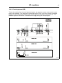
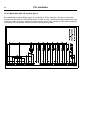
12.4.7 Machines with I/O module type 3
2 :C o m 1 0 0 -2 4 0 V A C
3 :In p u t P ric e re d u c tio n
1 :C o m 5 -2 4 V A C /D C
By maintaining an active (high) signal on connection 3 "Price reduction”, the price of the wash
program can be reduced. This function has a number of uses, including providing reductions during
a specific period of the day. Whilst the signal remains active (high), the price of the wash program is
reduced by the percentage entered in the price programming menu.
2
3
1
2
P-BUS
3
4
1
2
P-BUS
3
4
1
P U M P
D R A IN
CPU
1
D R A IN
1
H O T
1
C O LD
1
2
3
fig.6636
56
Troubleshooting
53
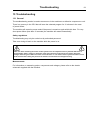
13 Troubleshooting
13.1 General
The troubleshooting section is used to trace errors in the machine to a defective component or unit.
There is a memory in the CPU that will save the selected program for 10 minutes in the case
of power failure.
The machine will restart in pause mode if the power is turned on again within this time. For very
short power failure (less than 10 seconds) the machine will restart automatically.
Safety regulations
Troubleshooting may only be carried out by authorised personnel.
Take care during all work on the machine while the power is on.
Take care when measuring the motor control system since all components have a potential difference of
approximately 300V in relation to protective earth and neutral.The components will contain dangerous
voltages when the green LED on the motor control board is on. The motor control system will remain live for
30-60 seconds after cutting the power to the machine and the motor has stopped running.
Measurements
For information on measuring points, components and voltages, please refer to the electric
schematic supplied with the machine.
Troubleshooting
54
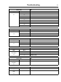
13.2 Error code
An error in the program or in the machine is indicated on the display by an error code and a
descriptive text.
The error codes are divided into different groups called “Major” comprising different error codes
called “Minor”.
The errors will be displayed as for example 11:2 DOOR OPEN.
The following is a description of all Major groups followed by a description of each error code.
Error code
Text
Major
Minor
MAIN COMMON
11
REAL TIME CLOCK OUT OF ORDER
10
13
INITIALIZING FAILED
Error code
Text
Major
Minor
MAIN WASHER
1
NO WATER
11
2
DOOR OPEN
3
DOOR LOCK FAIL
4
WATER LOW TEMP
5
WATER HIGH TEMP
6
WATER IN MACHINE
8
NO HEATING
9
DRUM OVERFILLED
10
DRUM NOT DRAINED
16
TIMEOUT HEATING
17
DOOR LOCK
27
LEVEL OFFSET
28
WATER LEVEL HIGH DLCU LEVEL LOW
29
WATER LEVEL LOW DLCU LEVEL HIGH
Error code
Text
Major
Minor
DRUM MOTOR
COMMON
1
O.H. DRUM MOTOR
2
NO MOTOR COMMUNINCATION
3
LOST MOTOR COMMUNICATION
20
Troubleshooting
Error code
Text
Major
Minor
DRUM MOTOR MCU
1
HEATSINK TOO HOT
21
2
MOTOR TOO HOT
3
NO INTERLOCK
5
MOTOR SHORT CIRCUIT
6
INTERLOCK HARDWARE
7
LOW DC VOLTAGE
8
HIGH DC VOLTAGE
15
MOTOR NOT FOLLOW
20
NO PARAMET. SET IN MCU
Error code
Text
Major
Minor
INTERNAL COM.
1
I/O BOARD MISHMASH
40
20
I/O INTERLOCK
21
I/O COMMUNICATION
Error code
Text
Major
Minor
INTERNAL COM. I/O
1
CHARGE CIRCUIT
41
2
SET SIGNAL NO TACHO
3
ACTUATOR CIRCUIT
Error code
Text
Major
Minor
INTERNAL COM.
I/O TYPE 6
1
INTERNAL ERROR
2
POSITION TEST
3
EXTRACT TEST
42
Error code
Text
Major
Minor
EXTERNAL COM.
PAYMENT
22
NO CBT COMMUNICATION
51
Error code
Text
Major
Minor
EXTERNAL COM.
CMIS
1
52
CMIS COMMUNICATION ERROR
55
56
Troubleshooting
13.3 Description of error codes and causes
MAIN COMMON
10:11 REAL TIME CLOCK OUT OF ORDER
The real time clock is used by the CPU, measuring time, power failure, error codes, etc.
The error code is activated if there is a time out in the communication with the internal real time
clock in the CPU or if the data sent to/from the real time clock is incorrect.
The error can only be removed by turning of the power to the machine for 30 seconds.
10:13 INITIALIZATION FAILED
The CPU has an internal time limit for initialization of the system.
The error code is activated if 15 seconds has expired during start up and the hardware still is not
initialized.
Press the control knob/start button to retry.
Troubleshooting
57
MAIN WASHER
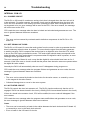
11:1 NO WATER
When filling with water, the level specified by the program must be attained within a certain time. This
time is normally set to 10 minutes but can vary depending on the type of machine and the software.
If the filling time exceeds the maximum allowed filling time, this error code will be displayed.
Long filling times can be caused by a blocked filler valve, defective filler valve, a break in the cable
between the filler valve control board, defective valve control board, leaking level system, etc.
11:2 DOOR OPEN
This error code can only arise during an on-going program.
This error code will be displayed if the control system detect that the input for door closed has
been deactivated during an on-going program.
This can be caused by for example a bad or defective door lock, loose cable to door lock, problem
with door lock edge connection.
11:3 DOOR LOCK FAIL
This error code can arise at program start. If the door lock doesn't lock within a certain time after
program start, this error code will be displayed.
This error code will also be displayed if the door switch for locked door signals that the door has
been unlocked during an on-going program.
This can be caused by for example a bad or defective door lock, loose cable to door lock, problem
with door lock edge connection.
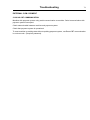
11:4 WATER LOW TEMP
This error code is displayed if the temperature around the temperature sensor is below approx. -9°C.
A low temperature means that the resistance in the sensor is too high, above approximately 23.7
kΩ. This can be caused if the machine for example has been standing outdoors, an open circuit in
the sensor, a break in the cable to the sensor.
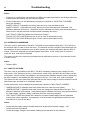
The resistance should be as shown in the table below:
Approximate values of an error free temperature sensor
T (°C)
R (Ω)
15
7.6
20
6.0
25
4.8
11:5 WATER HIGH TEMP
This error code is displayed if the temperature around the temperature sensor exceeds + 98°C.
A high temperature means that the resistance in the sensor is too low, lower than approximately
350 Ω. This can be caused by for example a short circuit in the sensor, break in the cable to
the sensor, etc.
58
Troubleshooting
11:6 WATER IN MACHINE
This error code can only arise in the case of rapid advance to the end of the program or if program
is aborted.
This error code will also appear if the level system has not indicated “empty drum” within a certain
time (approximately 3 min). This time may vary depending on the size of the machine.
Action
• Check drain for dirt.
• Blow through the level hose and check that it is not blocked and does not contain any water.
• Check in the service program that the level control is working correctly.
• Check for detergent overdosing.
11:8 NO HEATING
This error code is displayed if the temperature is rising too slowly when heating is active. The limit
for this error code is normally set to a water temperature increase of approximately 3°C per 10
minutes but can vary depending on the type of machine and software.
This error code can be caused by for example a defective heating element, a break in the power
supply to the heating element, defective heating contactor, etc.
On machines built for washing mops, it can be caused by too low level in the program step. The
lowest level for a mop program in the main wash with heating is 90 scale units.
11:9 DRUM OVERFILLED
This error code will be displayed if the drum has been filled with water above a pre-determined
level during an on-going program.
This error code can be caused by for example a blocked level hose, drops of water in the level tube,
defective filler valve, defective electronic filler control, etc.
Action
• Blow through the level hose and check that it is not blocked and does not contain any water.
• Check in the service program that the level control is working correctly.
• Check using the service program that all the water valves are working correctly.
11:10 DRUM NOT DRAINED
This error code is displayed if the water in the drum is not below a predetermined level when a
drain period has been completed in the program.
This error code can be caused by for example a blocked drain, blocked level hose, a water drop in
the level hose, defective level control, restricted drain lines to the machine, too many machines
emptying simultaneously into drain pipes that are too narrow, etc.
Action
• Check the drain installation and that the waste water can flow freely out from the machine without
any restrictions.
• Check the drain valve in the machine with regard to dirt.
• Blow through the level hose and check that it is not blocked and does not contain any water.
• Check in the service program that the level control is working correctly.
Troubleshooting
59
11:16 TIMEOUT HEATING
This error code is based on degrees/minutes. A check is made during water filling. If there is a drain
leakage there will be repeated fillings and therefore no error code from gradient check.
This timeout is an overall timeout that is started when heating is started. If heating time is longer
than set in MAX HEATING TIME (Config 2) this error code will be displayed.
11:17 DOOR LOCK
This error code is displayed if the door lock is locked at the start of the program, i.e. that the door is
locked although the timer has not requested locking.
11:27 LEVEL OFFSET
This error code arises if the level system indicates a level at the start of the program (when the
drum should be empty) that exceeds what the program unit can compensate for automatically.
This can be caused by for example blocked drain, blocked level hose, a drop of water in the level
hose, leaking level system, defective level control, etc.
Action
• Check drain for dirt.
• Blow through the level hose and check that it is not blocked and does not contain any water.
• Check in the service program that the level control is working correctly.
11:28 WATER LEVEL HIGH DLCU LEVEL LOW
The DLCU on I/O type 10 contains a mechanical level guard which ensures that there is no
water in the machine when the lock opens. To ensure that the level guard functions correctly, the
mechanical level guard is compared with a nominal value generated by the level system, which
is compared with the electronic level sensor.
When the water level exceeds the nominal value during first fill, a check is made to ensure that the
mechanical level guard is switched on, and if not, this error code is displayed.
Cause
• The level control can be damaged.
• Cross talk in the level control electrical system.
• Leakage in the level controls’ air hoses.
• Incorrect nominal value, possibly caused by a error in the electronic level control.
Action
• Check the level control function. (Switch-on level = 40 mm, switch-off level = 15 mm Wg).
• Check the cables and their connections. The voltage across the level controller should be 0 V
when the water level is < 15 mm Wg and 5 V when water level is > 40 mm Wg.
• Blow through the level hoses and check that they are not blocked and does not contain any water.
60
Troubleshooting
11:29 WATER LEVEL LOW DLCU LEVEL HIGH
The DLCU on I/O type 10 contains a mechanical level guard which ensures that there is no
water in the machine when the lock opens. To ensure that the level guard functions correctly, the
mechanical level guard is compared with a nominal value generated by the level system, which
is compared with the electronic level sensor.
When the mechanical level monitor is switched off during draining, the water level in the drum must
be below the nominal value measured by the electronic level control.
Cause
• The level control can be damaged.
• Cross talk in the level control electrical system.
• Leakage in the level controls’ air hoses.
• Incorrect nominal value, possibly caused by a error in the electronic level control.
Action
• Check the level control function. (Switch-on level = 40 mm, switch-off level = 15 mm Wg).
• Check the cables and their connections. The voltage across the level controller should be 0 V
when the water level is < 15 mm Wg and 5 V when water level is > 40 mm Wg.
• Blow through the level hoses and check that they are not blocked and does not contain any water.
Troubleshooting
61
DRUM MOTOR COMMON
20:1 O.H. DRUM MOTOR
Not valid for washer extractors with MCU.
This error code is activated if the overheating protection for the drum motor has trigged.
The overheating protection is automatically restored. When the overheating protection is restored
the error code is automatically reset and the ongoing program will continue. A long press on the
control knob/start button will make the CPU reset and ongoing program will be ended.
The error code can be trigged if:
• The motor is very warm. Check that the vent holes in the motor are not covered.
If the overheating protection is not trigged, but there is still an error code:
• Check the harness, connectors and functions by reading the electrical schematic and by using
the SHOW INPUTS menu when the machine is in service mode.
20:2 NO MOTOR COMMUNICATION
This error code arises if the first message sent from the CPU to the MCU was not replied to
during start up.
Action
• Check that there is power reaching the MCU. Check the fuses in the Protection Cable. If one of
the components in the Protection Cable is damaged, the cable must be replaced.
• Check that the indicator LED on the MCU is on. The LED can be seen by looking down by
the MCU edge connections.
• Check that the communication cable between the CPU board and the MCU is intact and not
damaged. Measure also with a reference instrument to see whether there is contact between all
the leads in the communication cable.
20:3 LOST MOTOR COMMUNICATION
This error code arises if the communication between the CPU and the MCU has stopped working.
Action
• Check that there is power reaching the MCU. Check the fuses in the Protection Cable. If one of
the components in the Protection Cable is damaged, the cable must be replaced.
• Check that the indicator LED on the MCU is on. The LED can be seen by looking down by
the MCU edge connections.
• Check that the communication cable between the CPU board and the MCU is intact and not
damaged. Measure also with a reference instrument to see whether there is contact between all
the leads in the communication cable.
62
Troubleshooting
DRUM MOTOR MCU
21:1 HEATSINK TOO HOT
This error code is generated by the MCU. There is a temperature sensor (NTC) mounted on the
MCU cooling flange next to the power transistors in the output stage. If the temperature of the
cooling flange gets too high (> 90°C) the error code will be set to protect the transistors.
The cause of high cooling flange temperature can be e.g. a stiff drum in combination with intensive
use and high ambient temperature. There may also be an error in the motor (sticking bearings or
short circuit in windings, which impairs the efficiency of the motor).
Action
• Make sure the drum turns easily.
• Check the value on the error code counter for the error code.
• Check the last 8 MCU error codes.
• Start a 90°C normal program with load on continuous operation and measure the temperature of
the motor and MCU.
• Replace the defective part.
21:2 MOTOR TOO HOT
This error code is generated by the MCU. Each time the motor is started from stationary, the MCU
will first measure the resistance between two phases in the motor. The MCU processor governs
the output transistors so that a DC current flows between two phases in the motor winding. The
actuation of the transistors is a measure of the voltage applied to the winding and the resistance
can be calculated using the current and voltage values. The resistance can then be converted to
a temperature since the winding resistance at 20°C and the temperature coefficient are known.
If the average value of the four latest temperature readings is higher than the maximum motor
temperature (e.g. 150°C), the error code will be activated.
The cause of high motor temperature can be a stiff drum, possibly in combination with intensive use
and high ambient temperature. There may also be an error in the motor (sticking bearings or short
circuit in windings, which impairs the efficiency of the motor). There could also be a contact error in
the connectors between the MCU and the motor or an error in the motor cable. An error in MCU
temperature measurement circuits can also occur.
Action
• Make sure the drum turns easily.
• Check the value on the error code counter for the error code.
• Check the last 8 MCU error codes.
• Measure the three phases to the phase resistors on the MCU motor connector (disconnect MCU
and take the reading in the cable connector) to make sure they are the same.
• Start a 90°C normal program with load on continuous operation and measure the temperature of
the motor and MCU.
• Replace the defective part.
Troubleshooting
63
21:3 NO INTERLOCK
This error code is generated by the MCU. The MCU must be powered with 230V / 50 or 60 Hz on
the interlock input in order to drive the motor. This signal is a confirmation that the door is closed
and locked.
MCU receives its commands to rotate the drum from the CPU via a serial communication link
between the MCU and CPU. Since the CPU also has access to the interlock signal, the CPU must
never send a run command to the MCU if the interlock signal is missing. If this does happen, this
error code will be activated.
The cause of this error code being activated can be e.g. a break in the cable leading the interlock
signal to the MCU. There may also be an error in the connector in the door lock, which connects
230V / 50Hz to the interlock signal. An error in the interlock circuits of the MCU can also set this
error code.
Action
• Use a measuring instrument to check that the interlock signal comes on X302:1-2 when the door
lock is activated. Read also bit 1 in the second byte under ”Motor Status” in the service program
(the bits are numbered from 0 to 7 where bit 0 is on the far right). If bit 1 in the second byte is 1
then the lock is open, while a 0 indicates that the lock is closed.
• Replace the defective part.
21:5 MOTOR SHORT CIRCIUT
This error code is generated by the MCU. The MCU reads the power consumption of the motor
continuously. If the current for some reason gets too high (= exceeds a certain limit), the MCU
will cut the current to the motor. After the motor has stopped (= tachometer indicates stationary
motor), the MCU will attempt to restart it. If the MCU then detects high motor current again, this
error code will be activated. If on restarting after a first short circuit, the MCU rotates normally,
an error code will not be activated.
Cause
This error code can be activated for a number of reasons:
• Short circuit in motor.
• Short circuit internally in motor winding (impaired efficiency, higher current consumption).
• Short circuit in motor cables.
• Short circuit in connectors.
• Drops of water causing short circuits in the motor connector.
• Short circuit in the MCU output transistors.
• Bad contact in tacho signal.
• Bad contact in interlock signal.
Troubleshooting
64
Action
• If the error is a stable one, it is generally not difficult to locate the defective unit through resistance
measurement and testing with the service program.
• Further information can be obtained by studying the contents of ”MCU FAULT LOGGER”.
Study the following:
SHORT CIRCUIT 2 (specifies how many times the error code has been active).
SHORT CIRCUIT 1 (specifies how many times the current limit has been exceeded. The
difference between short circuit 1 and short circuit 2 indicates how many times there has been a
short circuit 1 that has not been confirmed when restarting the motor).
LAST FAULT CODE N/8 (shows the 8 latest error codes).
TACHO CUT-OUT LOW RPM (can give a clue in case of intermittent errors).
TACHO CUT-OUT HIGH RPM (can give a clue in case of intermittent errors).
21:6 INTERLOCK HARDWARE
This error code is generated by the MCU. The MCU must be powered with 230V / 50 or 60 Hz on
the interlock input in order to drive the motor. The interlock circuits in the MCU have been split into
two channels so that a component error in MCU cannot give a false confirmation that the door is
locked. These two channels are checked against each other. If this check gives an incorrect
result this error code will be activated.
The reason for this error code being activated can be attributed to an error in the interlock circuits
in motor control.
Action
• Replace MCU.
21:7 LOW DC VOLTAGE
This error code is generated by the MCU. The MCU constantly measures the voltage over the
mains input. If the voltage is too low (= falls below a certain limit), the MCU will shut off the current
to the motor. Once the motor has stopped (= the tacho sensor indicates that the motor is stationary),
the MCU checks to see whether the input voltage is still low. If it is, this error code is activated.
The reason for this error code being activated can be low mains voltage or that the machine’s on/off
switch has been operated in an unsuitable manner.
Further information can be obtained by studying the contents of ”MCU FAULT LOGGER”:
• UNDERVOLTAGE 2 (specifies how many times this error code has been active).
• UNDERVOLTAGE 1 (specifies how many times the voltage has dropped below the limit. The
difference between undervoltage 1 and undervoltage 2 indicates how many times there has been
an undervoltage 1 without it being confirmed when the motor has stopped).
• LAST FAULT CODE N/8 (shows the 8 latest error codes) Undervoltages can be registered
even during normal operation. Consequently, a small number of registrations need not mean
that there is an error in the MCU.
Action
• Check that the supply voltage is stable and never drops below nominal voltage - 10%.
• Check the fuses and cables.
• Check the supply voltage in the network cabling and at the MCU in the machine.
Troubleshooting
65
21:8 HIGH DC VOLTAGE
This error code is generated by the MCU. The MCU constantly measures the voltage over the
mains input. If the voltage is too high (= exceeds a certain limit), the MCU will shut off the current to
the motor. Once the motor has stopped (= the tacho sensor indicates that the motor is stationary),
the MCU checks to see whether the input voltage is still high. If it is, this error code is activated.
The reason for this error code being activated can be high mains voltage (e.g. power surge).
Further information can be obtained by studying the contents of ”FC FAULT LOGGER”:
• OVERVOLTAGE 2 (specifies how many times this error code has been active)
• OVERVOLTAGE 1 (specifies how many times the voltage limit has been exceeded. The
difference between overvoltage 1 and overvoltage 2 gives the number of times overvoltage 1 has
occurred without it being confirmed when the motor has stopped).
• LAST FAULT CODE N/8 (shows the 8 latest error codes). Overvoltage registrations can also
occur if there is a bad contact in the tacho signal. Check also the following registers:
TACHO CUT-OUT LOW RPM (number of short tacho interruptions during wash rpm).
TACHO CUT-OUT HIGH RPM (number of short tacho interruptions during extraction rpm).
Action
• Check the tacho cables if there are many registrations in the TACHO CUT-OUT registers.
21:15 MOTOR NOT FOLLOW
This error code is generated by the MCU. The MCU must always receive information on the
rotation of the motor from the tacho sensor in order to rotate. If the tacho sensor is not working,
the motor can rotate for max. 10 seconds during the starting process. After this period, this error
code will be activated.
Cause
• Break in the cables between the tacho sensor and the MCU.
• Break in connectors in tacho cables.
• Break in one of the phases to the motor (cables or connectors). This error can be suspected if
the motor does not rotate for 10 seconds (the motor will not start with only two phases).
• Error in tacho generator.
• Error in tacho circuits in the MCU.
Further information can be obtained by studying the contents of ”FC ERROR LOGGER”. Study the
following:
• MOTOR NOT FOLLOW (specifies how many times this error code has occurred).
• LAST ERROR CODE N/8 (shows the 8 latest error codes).
• TACHO CUT-OUT LOW RPM (can give a clue in case of intermittent errors).
• TACHO CUT-OUT HIGH RPM (can give a clue in case of intermittent errors).
Action
• Replace the defective part.
66
Troubleshooting
21:20 NO PARAMET. SET IN MCU
The program unit has read from the MCU or I/O board that the interlock is not active.
The reason for interlock failure can be a problem with the hatch lock, damaged motor supply cables
or the I/O board with interlock voltage etc. The most probable error source is the I/O board.
Troubleshooting
67
INTERNAL COM.
40:1 I/O BOARD MISHMASH
The error code is activated if wrong I/O board is adressed to wrong position in the machine.
After addressing of I/O boards the CPU reads the type of board in every position. If there is a
mishmash between what the CPU reads and what the software expect on any address the error
code will be displayed.
Readdress all I/O boards. Use the electric schematic to find correct I/O board to address.
40:2 I/O INTERLOCK
The program unit has read from the I/O board that the interlock is not active.
The reason for interlock failure can be a problem with the hatch lock, damaged motor supply cables
or the I/O board with interlock voltage etc. The most probable error source is the I/O board.
40:21 I/O COMMUNICATION
The error code is activated if the CPU no longer communicate with one or more I/O boards.
There is an internal data bus between the different I/O boards in the machine with information
about inputs, outputs, etc. that the CPU use to control the machine. The error code is activated if
the CPU has lost communication with one or more I/O boards. The error will also be activated if
the service button is pressed on the wrong I/O board during configuration of I/O boards. If there
is communication between the I/O board and CPU the LED next to the service button will flash.
If there is no communication to the I/O board but power, the LED will light when the button is
pressed on the I/O board.
Check that all I/O boards are configured in I/O CONFIGURATION menu when the machine is
in service mode.
If all I/O boards present in the list check the LED and harness, connectors and functions by reading
the electrical schematic.
68
Troubleshooting
INTERNAL COM. I/O
41:1 CHARGE CIRCUIT
The DLCU on I/O board 10 contains an arming circuit that is charged when the door lock coil is
to be activated. For safety reasons, this arming circuit must be discharged when the door lock
coil is not to be activated. If the arming circuit for operating the door lock is charged when it is
not supposed to be, an error message will be sent to the CPU. If the error ceases, the message
will not be sent to the CPU.
CPU reads the error message when the door is locked and unlocked and generates an error. The
error is ignored between these two occasions.
Cause
• The error can bee caused by overloads and/or defective components in the DLCU on I/O
board 10.
41:2 SET SIGNAL NO TACHO
The DLCU on I/O board 10 counts the tacho pulses from the motor in order to guarantee that the
drum is stationary when the door is opened. To ensure that the signal from the tacho generator
is working correctly, DLCU compares the tacho signal to a digital bit value from the CPU, which
is due to the CPU having activated the motor. The tacho signal should always correspond to the
digital bit value and if the tacho signal is not present when the digital bit value is present, an error
message will be generated to CPU.
The error message is filtered in such a way that the digital bit value should have been on for 2
seconds; if this is the case, a check is made that the pulses from the tacho sensor are present when
the digital bit value ceases.
Internally the DLCU will automatically clear an error if it disappears during program run.
CPU reads the error message when the program finishes and generates an error code, the error
message is ignored between these two occasions.
Cause
• The error can be caused by breaks in the circuits for the tacho sensor, or caused by a error
in the magnet in the tacho sensor.
• Collateral damage due to a error in the motor system.
41:3 ACTUATOR CIRCUIT
The DLCU controls the door lock actuator coil. The DLCU checks continuously that the coil is
engaged. DLCU can detect a break in the circuit (>50 kΩ) (DLCU cannot detect a short in the circuit).
If there is a break in the actuator circuit, CPU will be notified; the error code will disappear if the
error ceases.
CPU reads the error message when the program starts and finishes and generates an error code,
the error message is ignored between these two occasions.
Cause
• The error can be caused by a break in the cables between the hatch lock and the I/O board 10,
or caused by a error in the hatch lock solenoid.
• Error or break in the I/O board 10 circuits.
Troubleshooting
Action
• If the error returns after a reset, and is not caused by a error in the hatch lock or the cables
for the hatch lock, change the I/O board 10.
69
70
Troubleshooting
INTERNAL COM. I/O TYPE 6
42:1 INTERNAL ERROR
Reading of A/D values out of range.
42:2 POSITION TEST
Position value out of range. Check that I/O module type 6 is still in correct position.
42:3 EXTRACT TEST
I/O module type 6 is not able to read any or too low values during extraction.
Troubleshooting
71
EXTERNAL COM. PAYMENT
51:22 NO CBT COMMUNICATION
Machine with payment system using serial communication to machine. Serial communication with
payment system interrupted.
Check network cable between machine and payment system.
Check that payment system is operational.
To reset machine to working state without repairing payment system, use Reset CBT communication
in service mode. (Requires password).
72
Troubleshooting
EXTERNAL COM. CMIS
52:1 CMIS COMMUNICATION ERROR
Communication between machine and network computer has been interrupted.
Check network cable between machine and network.
Check that CMIS on network computer is operational.
The machine can be operated but statistics could be affected and data could be lost.
Maintenance
73
14 Maintenance
14.1 Inspect the interior of the machine
Inspect the interior of the machine to ensure that no leaks are noticed.
During an actual wash cycle; disconnect the power to the machine and proceed as follows:
• Remove the top panel, the front and rear panel.
• Verify that all internal hoses do not leak.
• Check that water does not leak onto the floor.
• Inspect the belt. Adjust the tension or replace if necessary.
• If the heating time is unusually long, check the heating elements. If the water is very hard, check
whether there are lime deposits on the heating elements. Decalcify the elements if necessary.
Adapt the amount of deliming agent to the manufacturer’s guidelines.
• Never switch on the heating elements when there is no water in the machine. This will cause the
slow-blow fuse to trigger.
• Inspect the shock absorbers and coil springs.
lastpage
Electrolux Laundry Systems Sweden AB
341 80 Ljungby, Sweden
www.electrolux.com/laundrysystems
Share more of our thinking at www.electrolux.com