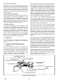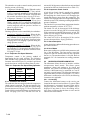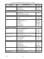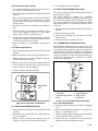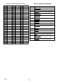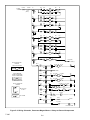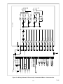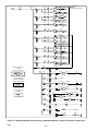
1
Bus Air Conditioning Equipment Models GR--45 GR--60 (N. A. O.) T--295 OPERATION AND SERVICE MANUAL BUS AIR CONDITIONING UNIT Models GR--45 GR--60 (N. A. O.) Carrier Refrigeration Operations Carrier Transicold Division, Carrier Corporation, P.O. Box 4805, Syracuse, N.Y. 13221 U. S. A. Carrier Corporation 2000 D Printed in U. S. A. 0300 SAFETY SUMMARY GENERAL SAFETY NOTICES The following general safety notices supplement the specific warnings and cautions appearing elsewhere in this manual. They are recommended precautions that must be understood and applied during operation and maintenance of the equipment covered herein. A listing of the specific warnings and cautions appearing elsewhere in the manual follows the general safety notices. FIRST AID An injury, no matter how slight, should never go unattended. Always obtain first aid or medical attention immediately. OPERATING PRECAUTIONS Always wear safety glasses. Keep hands, clothing and tools clear of the evaporator and condenser fans. No work should be performed on the unit until all circuit breakers and start-stop switches are placed in the OFF position, and power supply is disconnected. Always work in pairs. Never work on the equipment alone. In case of severe vibration or unusual noise, stop the unit and investigate. MAINTENANCE PRECAUTIONS Beware of unannounced starting of the evaporator and condenser fans. Do not open the unit cover before turning power off. Be sure power is turned off before working on motors, controllers, solenoid valves and electrical controls. Tag circuit breaker and power supply to prevent accidental energizing of circuit. Do not bypass any electrical safety devices, e.g. bridging an overload, or using any sort of jumper wires. Problems with the system should be diagnosed, and any necessary repairs performed, by qualified service personnel. When performing any arc welding on the unit, disconnect all wire harness connectors from the modules in the control box. Do not remove wire harness from the modules unless you are grounded to the unit frame with a static-safe wrist strap. In case of electrical fire, open circuit switch and extinguish with CO2 (never use water). SPECIFIC WARNINGS AND CAUTIONS WARNING DO NOT USE A NITROGEN CYLINDER WITHOUT A PRESSURE REGULATOR WARNING DO NOT USE OXYGEN IN OR NEAR A REFRIGERATION SYSTEM AS AN EXPLOSION MAY OCCUR. WARNING THE FILTER-DRIER MAY CONTAIN LIQUID REFRIGERANT. SLOWLY LOOSEN THE FLARE NUTS AND AVOID CONTACT WITH EXPOSED SKIN OR EYES. CAUTION Do not under any circumstances attempt to service the microprocessor. should a problem develop with the microprocessor, replace it. CAUTION If unit was recently operated, be careful of remaining hot coolant in the hoses when disassembling. Safety-1 T--295 TABLE OF CONTENTS PARAGRAPH NUMBER Page SAFETY SUMMARY . . . . . . . . . . . . . . . . . . . . . . . . . . . . . . . . . . . . . . . . . . . . . . . . . . . . . . . . . . . . . . . . . . . . . Safety-1 DESCRIPTION . . . . . . . . . . . . . . . . . . . . . . . . . . . . . . . . . . . . . . . . . . . . . . . . . . . . . . . . . . . . . . . . . . . . . . . . . . . . . . . 1-1 1.1 1.2 INTRODUCTION . . . . . . . . . . . . . . . . . . . . . . . . . . . . . . . . . . . . . . . . . . . . . . . . . . . . . . . . . . . . . . GENERAL DESCRIPTION . . . . . . . . . . . . . . . . . . . . . . . . . . . . . . . . . . . . . . . . . . . . . . . . . . . . . . 1.2.1 Apex Unit . . . . . . . . . . . . . . . . . . . . . . . . . . . . . . . . . . . . . . . . . . . . . . . . . . . . . . . . . . . . . . . . . . 1.2.2 Condensing Section . . . . . . . . . . . . . . . . . . . . . . . . . . . . . . . . . . . . . . . . . . . . . . . . . . . . . . . . . . 1.2.3 Evaporator Section . . . . . . . . . . . . . . . . . . . . . . . . . . . . . . . . . . . . . . . . . . . . . . . . . . . . . . . . . . . 1.2.4 Compressor Assembly . . . . . . . . . . . . . . . . . . . . . . . . . . . . . . . . . . . . . . . . . . . . . . . . . . . . . . . . 1.2.5 Fresh Air System . . . . . . . . . . . . . . . . . . . . . . . . . . . . . . . . . . . . . . . . . . . . . . . . . . . . . . . . . . . . 1.2.6 System Operating Controls And Components . . . . . . . . . . . . . . . . . . . . . . . . . . . . . . . . . . . . . 1.3 REFRIGERATION SYSTEM COMPONENT SPECIFICATIONS . . . . . . . . . . . . . . . . . . . . . . . . 1.4 ELECTRICAL SPECIFICATIONS -- MOTORS . . . . . . . . . . . . . . . . . . . . . . . . . . . . . . . . . . . . . . 1.5 ELECTRICAL SPECIFICATIONS -- SENSORS AND TRANSDUCERS . . . . . . . . . . . . . . . . . . 1.6 SAFETY DEVICES . . . . . . . . . . . . . . . . . . . . . . . . . . . . . . . . . . . . . . . . . . . . . . . . . . . . . . . . . . . . . 1.7 AIR FLOW . . . . . . . . . . . . . . . . . . . . . . . . . . . . . . . . . . . . . . . . . . . . . . . . . . . . . . . . . . . . . . . . . . . . 1.8 AIR CONDITIONING REFRIGERATION CYCLE . . . . . . . . . . . . . . . . . . . . . . . . . . . . . . . . . . . 1.9 HEATING CYCLE . . . . . . . . . . . . . . . . . . . . . . . . . . . . . . . . . . . . . . . . . . . . . . . . . . . . . . . . . . . . . 1.10 RELAY BOARD . . . . . . . . . . . . . . . . . . . . . . . . . . . . . . . . . . . . . . . . . . . . . . . . . . . . . . . . . . . . . . . 1.10.1 Permanent Magnet Motors with 2 speed switching from series to parallel connection (Option 1) . . . . . . . . . . . . . . . . . . . . . . . . . . . . . . . . . . . . . . . . . . . . . . . . . . . . . . . . 1.10.2 Electronically Communtated DC Motors with 2--speed Evaporator Input Signal (Option 2) . 1.11 LOGIC BOARD . . . . . . . . . . . . . . . . . . . . . . . . . . . . . . . . . . . . . . . . . . . . . . . . . . . . . . . . . . . . . . . . 1.12 CONTROL PANEL (Diagnostic Module) . . . . . . . . . . . . . . . . . . . . . . . . . . . . . . . . . . . . . . . . . . . . 1-9 1-11 1-12 1-13 OPERATION . . . . . . . . . . . . . . . . . . . . . . . . . . . . . . . . . . . . . . . . . . . . . . . . . . . . . . . . . . . . . . . . . . . . . . . . . . . . . . . . . 2-1 2.1 STARTING, STOPPING AND OPERATING INSTRUCTIONS . . . . . . . . . . . . . . . . . . . . . . . . . . 2.1.1 Power to Logic Board . . . . . . . . . . . . . . . . . . . . . . . . . . . . . . . . . . . . . . . . . . . . . . . . . . . . . . . . 2.1.2 Starting . . . . . . . . . . . . . . . . . . . . . . . . . . . . . . . . . . . . . . . . . . . . . . . . . . . . . . . . . . . . . . . . . . . . 2.1.3 Self-Test and Diagnostics (Check for Errors and/or Alarms) . . . . . . . . . . . . . . . . . . . . . . . . . . 2.1.4 Stopping . . . . . . . . . . . . . . . . . . . . . . . . . . . . . . . . . . . . . . . . . . . . . . . . . . . . . . . . . . . . . . . . . . . 2.2 PRE--TRIP INSPECTION . . . . . . . . . . . . . . . . . . . . . . . . . . . . . . . . . . . . . . . . . . . . . . . . . . . . . . . . 2.3 MODES OF OPERATION . . . . . . . . . . . . . . . . . . . . . . . . . . . . . . . . . . . . . . . . . . . . . . . . . . . . . . . 2.3.1 Temperature Control . . . . . . . . . . . . . . . . . . . . . . . . . . . . . . . . . . . . . . . . . . . . . . . . . . . . . . . . . 2.3.2 Cooling Mode . . . . . . . . . . . . . . . . . . . . . . . . . . . . . . . . . . . . . . . . . . . . . . . . . . . . . . . . . . . . . . 2.3.3 Heating Mode . . . . . . . . . . . . . . . . . . . . . . . . . . . . . . . . . . . . . . . . . . . . . . . . . . . . . . . . . . . . . . 2.3.4 Boost Pump . . . . . . . . . . . . . . . . . . . . . . . . . . . . . . . . . . . . . . . . . . . . . . . . . . . . . . . . . . . . . . . . 2.3.5 Vent Mode . . . . . . . . . . . . . . . . . . . . . . . . . . . . . . . . . . . . . . . . . . . . . . . . . . . . . . . . . . . . . . . . . 2.3.6 Fresh Air System . . . . . . . . . . . . . . . . . . . . . . . . . . . . . . . . . . . . . . . . . . . . . . . . . . . . . . . . . . . . 2.3.7 Compressor Unloader Control . . . . . . . . . . . . . . . . . . . . . . . . . . . . . . . . . . . . . . . . . . . . . . . . . . 2.3.8 Evaporator Fan Speed Selection . . . . . . . . . . . . . . . . . . . . . . . . . . . . . . . . . . . . . . . . . . . . . . . . 2.3.9 Condenser Fan Control . . . . . . . . . . . . . . . . . . . . . . . . . . . . . . . . . . . . . . . . . . . . . . . . . . . . . . . 2.3.10 Compressor Clutch Control . . . . . . . . . . . . . . . . . . . . . . . . . . . . . . . . . . . . . . . . . . . . . . . . . . . . i 1-1 1-2 1-2 1-2 1-3 1-4 1-4 1-4 1-5 1-5 1-5 1-5 1-6 1-6 1-8 1-9 2-1 2-1 2-1 2-1 2-1 2-1 2-3 2-3 2-3 2-3 2-3 2-3 2-3 2-3 2-4 2-4 2-4 T--295 TABLE OF CONTENTS (Continued) PARAGRAPH NUMBER 2.3.11 2.3.12 2.4 2.4.1 2.4.2 2.4.3 2.4.4 2.4.5 Page Alarm Description . . . . . . . . . . . . . . . . . . . . . . . . . . . . . . . . . . . . . . . . . . . . . . . . . . . . . . . . . . . Hour Meters . . . . . . . . . . . . . . . . . . . . . . . . . . . . . . . . . . . . . . . . . . . . . . . . . . . . . . . . . . . . . . . . MICROPROCESSOR DIAGNOSTICS . . . . . . . . . . . . . . . . . . . . . . . . . . . . . . . . . . . . . . . . . . Connecting . . . . . . . . . . . . . . . . . . . . . . . . . . . . . . . . . . . . . . . . . . . . . . . . . . . . . . . . . . . . . . . . . Control . . . . . . . . . . . . . . . . . . . . . . . . . . . . . . . . . . . . . . . . . . . . . . . . . . . . . . . . . . . . . . . . . . . . Diagnostic Mode . . . . . . . . . . . . . . . . . . . . . . . . . . . . . . . . . . . . . . . . . . . . . . . . . . . . . . . . . . . . System Parameters . . . . . . . . . . . . . . . . . . . . . . . . . . . . . . . . . . . . . . . . . . . . . . . . . . . . . . . . . . . Test Mode . . . . . . . . . . . . . . . . . . . . . . . . . . . . . . . . . . . . . . . . . . . . . . . . . . . . . . . . . . . . . . . . . 2-4 2-4 2-4 2-4 2-5 2-5 2-5 2-5 TROUBLESHOOTING . . . . . . . . . . . . . . . . . . . . . . . . . . . . . . . . . . . . . . . . . . . . . . . . . . . . . . . . . . . . . . . . . . . . . . . . . 3-1 3.1 3.2 SELF DIAGNOSTICS . . . . . . . . . . . . . . . . . . . . . . . . . . . . . . . . . . . . . . . . . . . . . . . . . . . . . . . . . . . SYSTEM ALARMS . . . . . . . . . . . . . . . . . . . . . . . . . . . . . . . . . . . . . . . . . . . . . . . . . . . . . . . . . . . . 3.2.1 Alarm Codes . . . . . . . . . . . . . . . . . . . . . . . . . . . . . . . . . . . . . . . . . . . . . . . . . . . . . . . . . . . . . . . 3.2.2 Activation . . . . . . . . . . . . . . . . . . . . . . . . . . . . . . . . . . . . . . . . . . . . . . . . . . . . . . . . . . . . . . . . . 3.2.3 Alarm Queue . . . . . . . . . . . . . . . . . . . . . . . . . . . . . . . . . . . . . . . . . . . . . . . . . . . . . . . . . . . . . . . 3.2.4 Alarm Clear . . . . . . . . . . . . . . . . . . . . . . . . . . . . . . . . . . . . . . . . . . . . . . . . . . . . . . . . . . . . . . . . 3.3 TROUBLESHOOTING . . . . . . . . . . . . . . . . . . . . . . . . . . . . . . . . . . . . . . . . . . . . . . . . . . . . . . . . . . 3.3.1 System Will Not Cool . . . . . . . . . . . . . . . . . . . . . . . . . . . . . . . . . . . . . . . . . . . . . . . . . . . . . . . . 3.3.2 System Runs But Has Insufficient Cooling . . . . . . . . . . . . . . . . . . . . . . . . . . . . . . . . . . . . . . . . 3.3.3 Abnormal Pressures . . . . . . . . . . . . . . . . . . . . . . . . . . . . . . . . . . . . . . . . . . . . . . . . . . . . . . . . . . 3.3.4 Abnormal Noise Or Vibrations . . . . . . . . . . . . . . . . . . . . . . . . . . . . . . . . . . . . . . . . . . . . . . . . . 3.3.5 Control System Malfunction . . . . . . . . . . . . . . . . . . . . . . . . . . . . . . . . . . . . . . . . . . . . . . . . . . . 3.3.6 No Evaporator Air Flow Or Restricted Air Flow . . . . . . . . . . . . . . . . . . . . . . . . . . . . . . . . . . . 3.3.7 Expansion Valve Malfunction . . . . . . . . . . . . . . . . . . . . . . . . . . . . . . . . . . . . . . . . . . . . . . . . . . 3.3.8 Heating Malfunction . . . . . . . . . . . . . . . . . . . . . . . . . . . . . . . . . . . . . . . . . . . . . . . . . . . . . . . . . 3-1 3-1 3-1 3-1 3-1 3-1 3-1 3-4 3-4 3-4 3-4 3-5 3-5 3-5 3-5 SERVICE . . . . . . . . . . . . . . . . . . . . . . . . . . . . . . . . . . . . . . . . . . . . . . . . . . . . . . . . . . . . . . . . . . . . . . . . . . . . . . . . . . . . 4-1 4.1 4.2 4.3 4.4 4.5 MAINTENANCE SCHEDULE . . . . . . . . . . . . . . . . . . . . . . . . . . . . . . . . . . . . . . . . . . . . . . . . . . . . OPENING TOP COVER . . . . . . . . . . . . . . . . . . . . . . . . . . . . . . . . . . . . . . . . . . . . . . . . . . . . . . . . . SUCTION AND DISCHARGE SERVICE VALVES . . . . . . . . . . . . . . . . . . . . . . . . . . . . . . . . . . . INSTALLING MANIFOLD GAUGE SET . . . . . . . . . . . . . . . . . . . . . . . . . . . . . . . . . . . . . . . . . . . PUMPING THE SYSTEM DOWN OR REMOVING THE REFRIGERANT CHARGE . . . . . . . 4.5.1 System Pump Down For Low Side Repair . . . . . . . . . . . . . . . . . . . . . . . . . . . . . . . . . . . . . . . . 4.5.2 Refrigerant Removal From An Inoperative Compressor. . . . . . . . . . . . . . . . . . . . . . . . . . . . . . 4.5.3 Pump Down An Operable Compressor For Repair . . . . . . . . . . . . . . . . . . . . . . . . . . . . . . . . . . 4.5.4. Removing Entire System Charge . . . . . . . . . . . . . . . . . . . . . . . . . . . . . . . . . . . . . . . . . . . . . . . . 4.6 REFRIGERANT LEAK CHECK . . . . . . . . . . . . . . . . . . . . . . . . . . . . . . . . . . . . . . . . . . . . . . . . . . 4.7 EVACUATION AND DEHYDRATION . . . . . . . . . . . . . . . . . . . . . . . . . . . . . . . . . . . . . . . . . . . . . 4.7.1 General . . . . . . . . . . . . . . . . . . . . . . . . . . . . . . . . . . . . . . . . . . . . . . . . . . . . . . . . . . . . . . . . . . . . 4.7.2 Preparation . . . . . . . . . . . . . . . . . . . . . . . . . . . . . . . . . . . . . . . . . . . . . . . . . . . . . . . . . . . . . . . . . 4.7.3 Procedure for Evacuation and Dehydrating System . . . . . . . . . . . . . . . . . . . . . . . . . . . . . . . . . T--295 ii 4-1 4-1 4-1 4-2 4-2 4-2 4-3 4-3 4-4 4-4 4-4 4-4 4-4 4-4 TABLE OF CONTENTS (Continued) PARAGRAPH NUMBER 4.8 Page ADDING REFRIGERANT TO SYSTEM . . . . . . . . . . . . . . . . . . . . . . . . . . . . . . . . . . . . . . . . . . . 4.8.1 Checking Refrigerant Charge . . . . . . . . . . . . . . . . . . . . . . . . . . . . . . . . . . . . . . . . . . . . . . . . . . 4-5 4-5 4.8.2 Adding Full Charge . . . . . . . . . . . . . . . . . . . . . . . . . . . . . . . . . . . . . . . . . . . . . . . . . . . . . . . . . . 4.8.3 Adding Partial Charge . . . . . . . . . . . . . . . . . . . . . . . . . . . . . . . . . . . . . . . . . . . . . . . . . . . . . . . . 4.9 CHECKING FOR NONCONDENSIBLES . . . . . . . . . . . . . . . . . . . . . . . . . . . . . . . . . . . . . . . . . . . 4-5 4-5 4-5 4.10 CHECKING AND REPLACING HIGH PRESSURE SWITCH . . . . . . . . . . . . . . . . . . . . . . . . . . 4.11 FILTER-DRIER . . . . . . . . . . . . . . . . . . . . . . . . . . . . . . . . . . . . . . . . . . . . . . . . . . . . . . . . . . . . . . . . 4.11.1 To Check Filter--Drier . . . . . . . . . . . . . . . . . . . . . . . . . . . . . . . . . . . . . . . . . . . . . . . . . . . . . . . . . 4.11.2 To Replace Filter--Drier . . . . . . . . . . . . . . . . . . . . . . . . . . . . . . . . . . . . . . . . . . . . . . . . . . . . . . . 4-5 4-6 4-6 4-6 4.12 CONDENSER COIL REPLACEMENT . . . . . . . . . . . . . . . . . . . . . . . . . . . . . . . . . . . . . . . . . . . . . 4.13 EVAPORATOR COIL REPLACEMENT . . . . . . . . . . . . . . . . . . . . . . . . . . . . . . . . . . . . . . . . . . . . 4.14 SERVICING THE HEAT VALVE . . . . . . . . . . . . . . . . . . . . . . . . . . . . . . . . . . . . . . . . . . . . . . . . . . 4.14.1 COIL REPLACEMENT . . . . . . . . . . . . . . . . . . . . . . . . . . . . . . . . . . . . . . . . . . . . . . . . . . . . . . 4.14.2 INTERNAL PART REPLACEMENT . . . . . . . . . . . . . . . . . . . . . . . . . . . . . . . . . . . . . . . . . . . . 4-6 4-7 4-7 4-7 4-7 4.14.3 REPLACE ENTIRE VALVE . . . . . . . . . . . . . . . . . . . . . . . . . . . . . . . . . . . . . . . . . . . . . . . . . . . 4.15 SERVICING THE LIQUID LINE SOLENOID VALVE . . . . . . . . . . . . . . . . . . . . . . . . . . . . . . . . . 4.15.1 Coil Replacement . . . . . . . . . . . . . . . . . . . . . . . . . . . . . . . . . . . . . . . . . . . . . . . . . . . . . . . . . . . . 4.15.2 Internal Part Replacement . . . . . . . . . . . . . . . . . . . . . . . . . . . . . . . . . . . . . . . . . . . . . . . . . . . . . 4.15.3. Replace Entire Valve . . . . . . . . . . . . . . . . . . . . . . . . . . . . . . . . . . . . . . . . . . . . . . . . . . . . . . . . . 4.16 CONDENSER FAN/MOTOR ASSEMBLY . . . . . . . . . . . . . . . . . . . . . . . . . . . . . . . . . . . . . . . . . . 4.16.1 Removal . . . . . . . . . . . . . . . . . . . . . . . . . . . . . . . . . . . . . . . . . . . . . . . . . . . . . . . . . . . . . . . . . . . 4.16.2 Inspection And Cleaning . . . . . . . . . . . . . . . . . . . . . . . . . . . . . . . . . . . . . . . . . . . . . . . . . . . . . . 4.16.3 Brush Replacement . . . . . . . . . . . . . . . . . . . . . . . . . . . . . . . . . . . . . . . . . . . . . . . . . . . . . . . . . . 4.17 REPLACING EVAPORATOR FAN . . . . . . . . . . . . . . . . . . . . . . . . . . . . . . . . . . . . . . . . . . . . . . . . 4.18 REPLACING RETURN AIR FILTERS . . . . . . . . . . . . . . . . . . . . . . . . . . . . . . . . . . . . . . . . . . . . . 4.19 THERMOSTATIC EXPANSION VALVE . . . . . . . . . . . . . . . . . . . . . . . . . . . . . . . . . . . . . . . . . . . . 4.19.1 Valve Replacement . . . . . . . . . . . . . . . . . . . . . . . . . . . . . . . . . . . . . . . . . . . . . . . . . . . . . . . . . . 4.19.2 Superheat Measurement . . . . . . . . . . . . . . . . . . . . . . . . . . . . . . . . . . . . . . . . . . . . . . . . . . . . . . . 4-7 4-8 4-8 4-8 4-8 4-8 4-8 4-9 4-9 4-9 4-9 4-9 4-9 4-10 4.20 COMPRESSOR MAINTENANCE . . . . . . . . . . . . . . . . . . . . . . . . . . . . . . . . . . . . . . . . . . . . . . . . . 4-10 4.20.1 Removing the Compressor . . . . . . . . . . . . . . . . . . . . . . . . . . . . . . . . . . . . . . . . . . . . . . . . . . . . 4.20.2 Transferring Compressor Clutch . . . . . . . . . . . . . . . . . . . . . . . . . . . . . . . . . . . . . . . . . . . . . . . . 4-10 4-11 4.20.3 Compressor Oil Level . . . . . . . . . . . . . . . . . . . . . . . . . . . . . . . . . . . . . . . . . . . . . . . . . . . . . . . . 4.20.4 Checking Unloader Operation . . . . . . . . . . . . . . . . . . . . . . . . . . . . . . . . . . . . . . . . . . . . . . . . . . 4.21 TEMPERATURE SENSOR CHECKOUT . . . . . . . . . . . . . . . . . . . . . . . . . . . . . . . . . . . . . . . . . . . 4.22 PRESSURE TRANSDUCER CHECKOUT . . . . . . . . . . . . . . . . . . . . . . . . . . . . . . . . . . . . . . . . . . 4.23 REPLACING SENSORS AND TRANSDUCERS . . . . . . . . . . . . . . . . . . . . . . . . . . . . . . . . . . . . . 4-12 4-12 4-13 4-13 4-13 4.24 LOGIC BOARD CONFIGURATION . . . . . . . . . . . . . . . . . . . . . . . . . . . . . . . . . . . . . . . . . . . . . . . 4-13 ELECTRICAL . . . . . . . . . . . . . . . . . . . . . . . . . . . . . . . . . . . . . . . . . . . . . . . . . . . . . . . . . . . . . . . . . . . . . . . . . . . . . . . . 5-1 5--1 INTRODUCTION . . . . . . . . . . . . . . . . . . . . . . . . . . . . . . . . . . . . . . . . . . . . . . . . . . . . . . . . . . . . . . . 5-1 INDEX . . . . . . . . . . . . . . . . . . . . . . . . . . . . . . . . . . . . . . . . . . . . . . . . . . . . . . . . . . . . . . . . . . . . . . . . . . . . . . . . . . iii Index-1 T--295 LIST OF ILLUSTRATIONS FIGURE NUMBER Page Figure 1-1. A/C Component Identification . . . . . . . . . . . . . . . . . . . . . . . . . . . . . . . . . . . . . . . . . . . . . . . . . . Figure 1-2. Apex Unit Components . . . . . . . . . . . . . . . . . . . . . . . . . . . . . . . . . . . . . . . . . . . . . . . . . . . . . . . . Figure 1-3. Condensing Section Components . . . . . . . . . . . . . . . . . . . . . . . . . . . . . . . . . . . . . . . . . . . . . . . . Figure 1-4. Evaporator Section Components . . . . . . . . . . . . . . . . . . . . . . . . . . . . . . . . . . . . . . . . . . . . . . . . . Figure 1-5. Air Flow Paths . . . . . . . . . . . . . . . . . . . . . . . . . . . . . . . . . . . . . . . . . . . . . . . . . . . . . . . . . . . . . . Figure 1-6. Refrigerant Flow Diagram . . . . . . . . . . . . . . . . . . . . . . . . . . . . . . . . . . . . . . . . . . . . . . . . . . . . . Figure 1-7. Heating Cycle Flow Diagram . . . . . . . . . . . . . . . . . . . . . . . . . . . . . . . . . . . . . . . . . . . . . . . . . . . Figure 1-8 Relay Board (Option 1) . . . . . . . . . . . . . . . . . . . . . . . . . . . . . . . . . . . . . . . . . . . . . . . . . . . . . . . . Figure 1-9 Relay Board (Option 2) . . . . . . . . . . . . . . . . . . . . . . . . . . . . . . . . . . . . . . . . . . . . . . . . . . . . . . . . Figure 1-10 Logic Board . . . . . . . . . . . . . . . . . . . . . . . . . . . . . . . . . . . . . . . . . . . . . . . . . . . . . . . . . . . . . . . . Figure 1-11. Micromate Control Panel . . . . . . . . . . . . . . . . . . . . . . . . . . . . . . . . . . . . . . . . . . . . . . . . . . . . . Figure 2-1 Capacity Control Diagram . . . . . . . . . . . . . . . . . . . . . . . . . . . . . . . . . . . . . . . . . . . . . . . . . . . . . . Figure 4-1. Opening Top Cover . . . . . . . . . . . . . . . . . . . . . . . . . . . . . . . . . . . . . . . . . . . . . . . . . . . . . . . . . . . Figure 4-2.Suction or Discharge Service Valve . . . . . . . . . . . . . . . . . . . . . . . . . . . . . . . . . . . . . . . . . . . . . . . Figure 4-3. Manifold Gauge Set . . . . . . . . . . . . . . . . . . . . . . . . . . . . . . . . . . . . . . . . . . . . . . . . . . . . . . . . . . Figure 4-4. Low Side Pump Down Connections . . . . . . . . . . . . . . . . . . . . . . . . . . . . . . . . . . . . . . . . . . . . . . Figure 4-5. Compressor Service Connections . . . . . . . . . . . . . . . . . . . . . . . . . . . . . . . . . . . . . . . . . . . . . . . . Figure 4-6. System Charge Removal Connections . . . . . . . . . . . . . . . . . . . . . . . . . . . . . . . . . . . . . . . . . . . . Figure 4-7. Checking High Pressure Switch . . . . . . . . . . . . . . . . . . . . . . . . . . . . . . . . . . . . . . . . . . . . . . . . . Figure 4-8. Filter--Drier Removal . . . . . . . . . . . . . . . . . . . . . . . . . . . . . . . . . . . . . . . . . . . . . . . . . . . . . . . . . Figure 4-9. Heat Valve . . . . . . . . . . . . . . . . . . . . . . . . . . . . . . . . . . . . . . . . . . . . . . . . . . . . . . . . . . . . . . . . . . Figure 4-10. Liquid Line Solenoid Valve . . . . . . . . . . . . . . . . . . . . . . . . . . . . . . . . . . . . . . . . . . . . . . . . . . . Figure 4-11. Condenser Fan/Motor Assembly . . . . . . . . . . . . . . . . . . . . . . . . . . . . . . . . . . . . . . . . . . . . . . . . Figure 4-12. Evaporator Fan Removal . . . . . . . . . . . . . . . . . . . . . . . . . . . . . . . . . . . . . . . . . . . . . . . . . . . . . Figure 4-13. Thermostatic Expansion Valve . . . . . . . . . . . . . . . . . . . . . . . . . . . . . . . . . . . . . . . . . . . . . . . . . Figure 4-14.Thermostatic Expansion Valve Bulb and Thermocouple . . . . . . . . . . . . . . . . . . . . . . . . . . . . . . Figure 4-15.Removing Bypass Piston Plug . . . . . . . . . . . . . . . . . . . . . . . . . . . . . . . . . . . . . . . . . . . . . . . . . . Figure 4-16. Compressor Clutch . . . . . . . . . . . . . . . . . . . . . . . . . . . . . . . . . . . . . . . . . . . . . . . . . . . . . . . . . . Figure 4-17. Compressors . . . . . . . . . . . . . . . . . . . . . . . . . . . . . . . . . . . . . . . . . . . . . . . . . . . . . . . . . . . . . . . Figure 4-18 Transducer Terminal Location . . . . . . . . . . . . . . . . . . . . . . . . . . . . . . . . . . . . . . . . . . . . . . . . . . Figure 5--1. Electrical Wiring Schematic Diagram - Legend . . . . . . . . . . . . . . . . . . . . . . . . . . . . . . . . . . . . . Figure 5--2. Wiring Schematic, Permanent Magnet Motors - Interconnection . . . . . . . . . . . . . . . . . . . . . . . Figure 5--3. Wiring Schematic, Permanent Magnet Motors - Relays to External Components . . . . . . . . . . Figure 5--4. Wiring Schematic, Electronically Communtated Motors - Interconnection . . . . . . . . . . . . . . . Figure 5--5. Wiring Schematic, Electronically Communtated Motors - Relays To External Components . . T--295 iv 1-1 1-2 1-3 1-4 1-6 1-7 1-8 1-9 1-11 1-12 1-13 2-2 4-1 4-2 4-2 4-3 4-3 4-4 4-6 4-6 4-7 4-8 4-8 4-9 4-9 4-10 4-11 4-11 4-12 4-13 5-2 5-3 5-4 5-5 5-6 LIST OF TABLES TABLE NUMBER Page Table 2-1. Evaporator Fan Speed Relay Operation . . . . . . . . . . . . . . . . . . . . . . . . . . . . . . . . . . . . . . . . . . . . . Table 2-2. Controller Test List . . . . . . . . . . . . . . . . . . . . . . . . . . . . . . . . . . . . . . . . . . . . . . . . . . . . . . . . . . . . . Table 2-3. Parameter Codes . . . . . . . . . . . . . . . . . . . . . . . . . . . . . . . . . . . . . . . . . . . . . . . . . . . . . . . . . . . . . . . Table 3-2 Alarm Codes . . . . . . . . . . . . . . . . . . . . . . . . . . . . . . . . . . . . . . . . . . . . . . . . . . . . . . . . . . . . . . . . . . Table 3-3 General System Troubleshooting Procedures . . . . . . . . . . . . . . . . . . . . . . . . . . . . . . . . . . . . . . . . . Table 4-1. Temperature Sensor Resistance . . . . . . . . . . . . . . . . . . . . . . . . . . . . . . . . . . . . . . . . . . . . . . . . . . . Table 4-2. PressureTransducer Voltage . . . . . . . . . . . . . . . . . . . . . . . . . . . . . . . . . . . . . . . . . . . . . . . . . . . . . . Table 4-3. Logic Board Configuration . . . . . . . . . . . . . . . . . . . . . . . . . . . . . . . . . . . . . . . . . . . . . . . . . . . . . . . v 2-4 2-5 2-6 3-2 3-4 4-13 4-14 4-14 T--295 SECTION 1 DESCRIPTION 1.1 INTRODUCTION system, the air conditioning and heating equipment interfaces with electrical cabling, refrigerant piping, engine coolant piping (for heating), duct work and other components furnished by the bus manufacturer. This manual contains Operating Instructions, Service Instructions and Electrical Data for the Model GR Air Conditioning and Heating equipment furnished by Carrier Transicold Division as shown in Table 1-1. Model GR systems consists of an Apex Unit, containing the condenser and evaporator and an engine compartment mounted compressor. To complete the Operation of the units is controlled automatically by a microprocessor based Micromax Controller which maintains the vehicle’s interior temperature at the desired set point. MODEL SERIES Table 1-1. Model COMPRESSOR GR45 ROOF MOUNTED ROOF MOUNTED 05K 05G GR60 CONDENSER FANS EVAPORATOR FANS 4 6 4 6 MANUAL/FORM NUMBER Table 1-2. Additional Support Manuals EQUIPMENT COVERED TYPE OF MANUAL 62--02491 62--02460 62--02756 T--200 O5K Compressor O5K Compressor O5G Compressor O5G Compressor Operation and Service Parts List Operation and Service Parts List 5 8 7 6 4 3 2 1 13 1. 2. 3. 4. 5. 6. 7. 12 11 Compressor Refrigerant Lines Compressor Harness Heat Valve Electronics Boards Apex Unit Main Harness 10 9 8. 9. 10. 11. 12. 13. Driver Control Power Harness Power Relay Battery Alternator Discharge Check Valve Figure 1-1. A/C Component Identification 1-1 T--295 1.2 GENERAL DESCRIPTION section, evaporator section, Micromax electronics, and the Fresh Air System. All components are accessible by lifting the top cover. Descriptions of the systems are provided in the following sub paragraphs. 1.2.1 Apex Unit The apex unit (see Figure 1-2) includes the condensing 2 1 3 11 10 4 5 6 8 9 1. Top Cover 2. Gas Spring (2) 3. Condenser Section (See Figure 1-3) 4. Evaporator Section (See Figure 1-4) 5. Base 6. Fresh Air System 7. Gas Spring Support (2) 8. Lock (2) 9. Serial Plate 7 10. 11. Hinge Condenser Fan Grille (4-GR45, 6-GR60) 12. Front Drain (2)* 13. Intermediate Drain (2)* 14. Evaporator Rear Drain (2)* 15. Condenser Rear Drain (2)* * Not Shown Figure 1-2. Apex Unit Components (GR-60 Shown) pressure into a liquid at high temperature and pressure. The condenser fans circulate ambient air across the The condensing section (Figure 1-3) includes the outside of the condenser tubes at a temperature lower condenser coils, fan and motor assemblies, filter-drier, than refrigerant circulating inside the tubes; this results receiver, liquid line solenoid valve, service valves, and in condensation of the refrigerant into a liquid. The an ambient temperature sensor. filter-drier removes moisture and debris from the liquid The condenser coils provide heat transfer surface for refrigerant before it enters the thermostatic expansion condensing refrigerant gas at a high temperature and valve in the evaporator assembly. 1.2.2 Condensing Section T--295 1-2 The receiver collects and stores liquid refrigerant. The receiver is fitted with upper and lower liquid level sight glasses to enable determining refrigerant liquid level. The receiver is also fitted with a fusible plug which protects the system from unsafe high pressure conditions. The liquid line solenoid valve closes when system is shut down to prevent flooding of coils with liquid refrigerant. The service valves enable isolation of the filter-drier for service. The ambient temperature 1 2 sensor measures ambient temperature and sends an electrical signal to the controller. The discharge check valve is a spring loaded, normally closed valve that opens with the flow of refrigerant from the compressor. When the compressor clutch is disengaged, the discharge check valve will close, preventing the flow of high pressure liquid from the condenser back into the compressor. 4 3 5 6 13 7 12 8 9 11 1. 2. 3. 4. 5. 6. 7. 8. 10 Condenser Coil (2) Receiver Protection Plate Service Valve Discharge Line Precharge Valve Liquid Line Solenoid Valve Filter Drier Upper Support 9. 10. 11 12. 13. Filter Drier Filter Drier Lower Support Condenser Fan and Motor Assembly (4-GR45, 6-GR60) Condenser Coil Fastener (4) Condenser Motor Support (4-GR45, 6-GR60) Figure 1-3. Condensing Section Components (GR-60 Shown) circulating over the outside surface of the tubes, thus providing heating. The fans circulate the air over the The evaporator section (Figure 1-4) includes the coils. The air filters remove dirt particles from the air evaporator coils, six fan and motor assemblies, before it passes over the coils. The thermostatic evaporator/heater coil assemblies, a thermostatic expansion valve meters flow of refrigerant entering the expansion valve and condensate drain connections. evaporator coils. The heat valve controls the flow of The evaporator coils provide heat transfer surface for engine coolant water to the heating coils upon receipt of transferring heat from air circulating over the outside a signal from the controller. The condensate drain the coil to refrigerant circulating inside the tubes; thus connections provide a means for connecting tubing for providing cooling. The heating coils provide heat disposing of condensate collected on the evaporator transfer surface for transferring heat from engine coils during cooling operation. coolant water circulating inside the tubes to air 1.2.3 Evaporator Section 1-3 T--295 1 2 3 4 5 6 7 8 9 1. 2. 3. 4. Evaporator Coil With Integrated 5. Evaporator Motor (4-GR45, Heating Coil (2) 6-GR60) Protection Plate 6. Suction Line Expansion Valve 7. Heating Lines Evaporator Motor Fastening Clamps 8. Service Valve (4-GR45, 6-GR60) 9. Evaporator Harness Figure 1-4. Evaporator Section Components (GR-60 Shown) into the air entering the evaporator coil. For additional information on air flow, refer to paragraph 1.7. The compressor assembly includes the refrigerant compressor, clutch assembly, suction and discharge 1.2.6 System Operating Controls And Components service valves, high pressure switch, low pressure switch, suction and discharge servicing (charging) ports The system is operated by a Carrier Transicold and electric solenoid unloaders. Micromax microprocessor controller which consist of a logic board (Figure 1-10), relay board (Figure 1-8 or The compressor raises the pressure and temperature of Figure 1-9), and manual operator switches. The manual the refrigerant and forces it into the condenser tubes. operating switches are located on the drivers control and The clutch assembly provides a means of belt driving may consist of a single OEM supplied ON/OFF switch, the compressor by the bus engine. The suction and additional OEM supplied switches or a Carrier discharge service valves enable servicing of the Transicold supplied Micromate control panel compressor. Suction and discharge servicing (charging) (Figure 1-11). The logic board regulates the operational ports mounted on the service valves enable connection cycles of the system by energizing or de--energizing of charging hoses for servicing of the compressor, as relays on the relay board in response to deviations in well as other parts of the refrigerant circuit. The high interior temperature. Modes of operation include pressure switch contacts open on a pressure rise to shut Cooling, Heat and Vent. On systems fitted with only an down the system when abnormally high refrigerant ON/OFF switch and on systems with the Micromate set pressures occur. The electric unloaders provide a means in the AUTO mode, the logic board will cycle the of controlling compressor capacity, which enables system between the operating modes as required to control of temperature inside the bus. For more detailed maintain desired set point temperature. information on the compressor, refer to manual number 62-02756. In the vent mode the evaporator fans are operated to circulate air in the bus interior. 1.2.5 Fresh Air System The Fresh Air System (6, Figure 1-2) consists of a In the heat mode the heat valve is opened to allow a flow damper and damper operator. The damper operator may of engine coolant through the heat section of the be controlled by the driver, if a switch is provided. In the evaporator coil. The evaporator fans operate to circulate automatic mode, it is controlled by the Micromax to air over the evaporator coil in the same manner as the open and close the damper to allow addition of fresh air vent mode. 1.2.4 Compressor Assembly T--295 1-4 In the cooling mode the compressor is energized while the evaporator and condenser fans are operated to provide refrigeration as required. The compressor is fitted with cylinder unloaders to match compressor capacity to the bus requirements. Once interior temperature reaches the desired set point, the system may operate in the clutch cycle or reheat mode. A controller programmed for clutch cycle will de--energize the compressor clutch and allow the system to operate in the vent mode until further cooling is required. A controller programmed for reheat will maintain compressor operation and open the heat valve to allow reheating of the return air. In the reheat mode interior temperature is maintained at the desired set point while additional dehumidification takes place. ECDC* p Evaporator Motor 27.5 VDC Horsepower (kW) Full Load Amps (FLA) Operating Speed High/Low (RPM) Bearing Lubrication Horsepower (kW) Full Load Amps (FLA) Operating Speed High/Low (RPM) Bearing Lubrication 1.3 REFRIGERATION SYSTEM COMPONENT SPECIFICATIONS 14.3 lb (6.5 kg) Compressor No of Cylinders Weight - Dry Oil Charge GR45 GR60 05K 4 108 lbs (49 kg) 5.5 pints (2.6 liters) 05G 6 137 lbs (62 kg) 6.75 pints (3.2 liters) 1/8 (.09) 9 18 1.5 ELECTRICAL SPECIFICATIONS -- SENSORS AND TRANSDUCERS a. Suction and Discharge Pressure Transducer Supply Voltage: 4.5 to 5.5 vdc (5 vdc nominal) Supply current: 8 mA maximum Output Range: 8K ohms minimum Input Range: --6.7 to 450 psig (--0.46 to 30.62 bar) Output Current: -1.5 mA minimum to 1.5 mA maximum Output Voltage: vdc = 0.0098 x psig + 0.4659 (See Table 4-2 for calculations.) Oil Level: Level in sight glass between Min.--Max marks on compressor crankcase (curbside) Approved Compressor Oils - R-134a: Castrol: Icematic SW68C Mobil: EAL Arctic 68 ICI: Emkarate RL68H b. Temperature Sensors Input Range: --52.6 to 158F (--47 to 70C) Output: NTC 10K ohms at 77F (25C) (See Table 4-1 for calculations.) c. Thermostatic Expansion Valve: Superheat Setting (Non-externally adjustable): 10 to 12F MOP Setting (Nonadjustable): 55 ±4 psig (3.74 ±2.27 bar) 1.6 SAFETY DEVICES System components are protected from damage caused by unsafe operating conditions with safety devices. Safety devices with Carrier Transicold supplied equipment include high pressure switch (HPS), low pressure switch (LPS), circuit breakers and fuses. d. High Pressure Switch (HPS): Opens at: 300 ±10 psig (20.41 ±0.68bar) Closes at: 200 ±10 psig (13.61 ±0.68bar) a. Pressure Switches High Pressure Switch (HPS) During the A/C mode, compressor operation will automatically stop if the HPS switch contacts open due to an unsafe operating condition. Opening HPS contacts de-energizes, through the controller, the compressor clutch shutting down the compressor. The high pressure switch (HPS) is installed in the center head of the compressor. e. Low Pressure Switch (LPS) Opens at: 6 ±3psig (0.41 ±0.20 bar) Closes at: 25 ±3 psig (1.7 ±0.20 bar) 1.4 0.15(.11) 7 Permanent Magnet 24 VDC 12 VDC 4252/ 4200/ NA 1850 Factory Lubricated (additional grease not required) * Electronically Communicated Direct Current a. Refrigerant Charge b. Compressor UNIT MODEL 1/8 (.09) 9.5 19 4252/ 4200/ 3165 1850 Factory Lubricated (additional grease not required) b. Condenser Fan Motor ECDC* Condenser Motor 24 VDC Controls may also be provided to allow manual operation of the evaporator fans in low or high speed and manual control of the fresh air damper in the open or closed position. R--134a 0.34(.25) 8.4 Permanent Magnet 24 VDC 12 VDC ELECTRICAL SPECIFICATIONS -- MOTORS a. Evaporator Fan Motor 1-5 T--295 Low Pressure Switch (LPS) The low pressure switch is installed in the compressor and opens on a pressure drop to shut down the system when a low pressure condition occurs. In addition, if the control monitors a pressure less than 10 psig (0.68 bar)by the suction pressure transducer mounted in the evaporator section, the system will be shut down for at least one minute. The compressor raises the pressure and the temperature of the refrigerant and forces it into the condenser tubes. The condenser fan circulates surrounding air (which is at a temperature lower than the refrigerant) over the outside of the condenser tubes. Heat transfer is established from the refrigerant (inside the tubes) to the condenser air (flowing over the tubes). The condenser tubes have fins designed to improve the transfer of heat from the refrigerant gas to the air; this removal of heat causes the refrigerant to liquefy, thus liquid refrigerant leaves the condenser and flows to the receiver. b. Fuses and Circuit Breakers The Relay Board is protected against high current by an OEM supplied 150 amp fuse. Independent 15 amp circuit breakers protect each motor while the output circuits are protected by an additional 15 amp circuit breaker. During a high current condition, the breaker (or OEM fuse) may open. When power is removed from a device, a breaker alarm will be generated. The receiver serves as a liquid refrigerant reservoir so that a constant supply of liquid is available to the evaporators as needed, and acts as a storage space when pumping down the system. The receiver is equipped with sight glasses to observe the refrigerant for restricted flow and correct charge level. c. Ambient Lockout The refrigerant leaves the receiver and passes through the receiver outlet/service valve, through a filter-drier where an absorbent keeps the refrigerant clean and dry. The ambient temperature sensor located in the condenser section measures the condenser inlet air temperature. When the temperature is below the cut out set point the compressor is locked out until the temperature rises above the cut in setting. The set points may be programmed to cut out at 45F 7.2C) and cut in at 50F 10C) or cut out at 25 F --3.9C) and cut in at 45F 7.2C) in accordance with bus purchase specification. This setting protects the compressor from damage caused by operation at low pressures. From the filter-drier, the liquid refrigerant then flows through the liquid line solenoid valve to the thermostatic expansion valve. the thermal expansion valve reduce pressure and temperature of the liquid and meters the flow of liquid refrigerant to the evaporator to obtain maximum use of the evaporator heat transfer surface. The low pressure, low temperature liquid that flows into the evaporator tubes is colder than the air that is circulated over the evaporator tubes by the evaporator fans (fans). Heat transfer is established from the evaporator air (flowing over the tubes) to the refrigerant (flowing inside the tubes). The evaporator tubes have aluminum fins to increase heat transfer from the air to the refrigerant; therefore the cooler air is circulated to the interior of the bus. Liquid line solenoid valve closes during shutdown to prevent refrigerant flow. 1.7 AIR FLOW The paths for ambient air through the condenser and coach air through the evaporator are illustrated in Figure 1-5. 1.8 AIR CONDITIONING REFRIGERATION CYCLE When air conditioning (cooling) is selected by the controller, the unit operates as a vapor compression system using R-134a as a refrigerant (see Figure 1-6). The main components of the system are the reciprocating compressor, air-cooled condenser coils, receiver, filter-drier, thermostatic expansion valve, liquid line solenoid valve and evaporator coils. The transfer of heat from the air to the low temperature liquid refrigerant in the evaporator causes the liquid to vaporize. This low temperature, low pressure vapor passes through the suction line and returns to the compressor where the cycle repeats. CONDENSER AIR FLOW 3. THROUGH FAN 4. RETURN TO AMBIENT 2. THROUGH CONDENSER 1. FROM DAMPER (IF ACTIVE) 1. FROM AMBIENT 2. FROM COACH 3. THROUGH EVAPORATOR 4. THROUGH FAN 5. RETURN TO COACH Figure 1-5. Air Flow Paths T--295 1-6 EVAPORATOR AIR FLOW 1 2 3 4 5 6 7 8 9 10 11 A 12 13 16 11 A 14 RECEIVER 16 DISCHARGE LIQUID SUCTION DISCHARGE SUCTION 15 17 MAIN ENGINE RADIATOR 18 VIEW A-A COMPRESSOR 1. 2. 3. 4. 5. 6. 7. 8. 9. Condenser Fan Assembly Evaporator Fan Assembly Expansion Valve Expansion Valve Equalizer Line Liquid Line Precharge Valve Expansion Valve Bulb Pressure Transducer, Low Side Service Port, Low Side 10. 11. 12. 13. 14. 15. 16. 17. 18. Pressure Transducer, High Side Service Valve With Port Liquid Line Solenoid Valve Filter Drier Service Port, High Side Discharge Check Valve Receiver Refrigerant Sight Glass Moisture Indicator Figure 1-6. Refrigerant Flow Diagram (GR60 Shown) 1-7 T--295 HEAT VALVE BOOST PUMP SUPPLY RETURN MAIN ENGINE RADIATOR COMPRESSOR Figure 1-7. Heating Cycle Flow Diagram (GR60 Shown) inside the bus. Engine coolant (glycol solution) is circulated through the heating circuit by the engine and Heating circuit (Figure 1-7) components furnished by Carrier Transicold include the integral evaporator coil an auxiliary boost water pump. When the heat valve heater cores and a solenoid operated heat valve. solenoid is energized, the valve will open to allow engine coolant to flow through the heater coil. The valve Components furnished by the bus manufacturer include auxiliary heater and boost water pump. The controller is normally closed so that if a failure occurs, the system automatically controls the heat valve during the heating will be able to cool. and reheat modes to maintain required temperatures 1.9 HEATING CYCLE T--295 1-8 1.10 RELAY BOARD CB 11 K3 CB 1 CB 5 K7 K15 K16 D2 D6 K4 K8 K6 D14 D17 CB 4 K11 K10 K20 K19 K13 K12 D85 CB 9 D26 D30 K18 JP4 K5 CF1 CF2 D38 D41 CB 10 4 5 6 2 3 1 CB 3 CB 8 JP3 K2 CB 6 EF1 EF2 4 5 2 3 1 CB 12 CB 2 2 3 1 EF3 EF4 EF6 EF5 CF6 CF3 CF4 K24 D57 D54 K17 K9 CB 7 JP5 K1 K14 3 4 1 2 CB 13 JP6 1.10.1 Permanent Magnet Motors with 2 speed switching from series to parallel connection (Option 1) D63 D60 D72 D66 D51 D69 CF5 JP1 K22 K21 K23 JP2 Figure 1-8 Relay Board (Option 1) low speed. a. Relays K1 Energizes evaporator fans 1 & 2 in high speed K12 Connects the negative side of condenser fan or evaporator fans 1,2,3 & 4 in low speed. 5 to ground in high speed. Connects the K2 Energizes evaporator fans 3 & 4 in high speed negative side of condenser fan 5 to (not energized in low speed). the positive side of condenser fan 6 in K3 Energizes evaporator fan 5 in high speed or low speed. evaporator fans 5 & 6 in low speed. K13 Energizes the A/C clutch. K4 Energizes evaporator fan 6 in high speed (not K14 Energizes unloader 1. energized in low speed). K15 Energizes unloader 2. K5 Connects the negative side of evaporator fans K16 Energizes the fresh air damper. 1 & 2 to ground in high speed. Connects the K17 Energizes the heat valve. negative side of evaporator fans 1 & 2 to K18 Energizes the fault light output. positive side of evaporator fans 3 & 4 in K19 Energizes the Boost Pump. low speed K20 Energizes the spare output. K6 Connects the negative side of evaporator fan K21 Is energized by the logic board to turn the 5 to ground in high speed. Connects the evaporator fans on high. The contacts of this negative side of evaporator fan 5 to relay energize the coils of relays K1, K2, positive side of evaporator fan 6 in K3 & K4. low speed K22 Is energized by the logic board to turn the K 7 Energizes condenser fans 1 & 2 in high speed evaporator fans on low. The contacts of this or condenser fans 1,2,3 & 4 in low speed relay energize the coils of relays K1, K3, K 8 Energizes condenser fans 3 & 4 in high speed K5 & K6. (not energized in low speed). K23 Is energized by the logic board to turn the K 9 Energizes condenser fan 5 in high speed or condenser fans on high. The contacts of this condenser fans 5 & 6 in low speed. relay energize the coils of relays K7, K8, K10 Energizes condenser fan 6 in high speed K9 & K10. (not energized in low speed). K24 Is energized by the logic board to turn the K11 Connects the negative side of condenser fans condenser fans on low. The contacts of this 1 & 2 to ground in high speed. Connects the relay energize the coils of relays K7, K9, negative side of condenser fans 1 & 2 to K11 & K12. the positive side of condenser fans 3 & 4 in 1-9 T--295 b. Thermal Circuit Breakers CB 1 Evaporator Fan #1. 15 Amp. CB 2 Evaporator Fan #2. 15 Amp. CB 3 Evaporator Fan #3. 15 Amp. CB 4 Evaporator Fan #4. 15 Amp. CB 5 Evaporator Fan #5. 15 Amp. CB 6 Evaporator Fan #6. 15 Amp. CB 7 Condenser Fan #1. 15 Amp. CB 8 Condenser Fan #2. 15 Amp. CB 9 Condenser Fan #3. 15 Amp. CB10 Condenser Fan #4. 15 Amp. CB11 Condenser Fan #5. 15 Amp. CB12 Condenser Fan #6. 15 Amp. CB13 A/C clutch, Unloaders 1&2, Fresh Air Damper, Heat Valve, Fault Output and Spare output. 15 Amp JP6 Unloaders 1 & 2. d. LEDS D 2 Relay K1 output active (evaporator fans 1,2,3 & 4 energized) D 6 Will be brightly lit if evaporator fans 1, 2, 3 & 4 are on high. Will be at half intensity of they are on low. D14 Relay K3 output active (evaporator fans 5 & 6 energized). D17 .Will be brightly lit if evaporator fans 5 &6 are on high. Will be at half intensity of they are on low. D26 Relay K7 output active (condenser fans 1, 2, 3 & 4 energized). D30 Will be brightly lit if condenser fans 1, 2, 3 & 4 are on high. Will be at half intensity of they are on low. D38 Relay K9 output active (condenser fans 5 & 6 energized). D41 Will be brightly lit if condenser fans 5 &6 are on high. Will be at half intensity of they are on low. D51 A/C clutch output active. D54 Unloader 1 output active. D57 Unloader 2 output active. D60 Fresh air output active. D63 Heat valve output active. D66 Fault output active. D69 Boost pump output active. D72 Spare output active. c. Connectors EF1-EF6 Evaporator fans. CF1-CF4 Condenser fans. JP1 External evaporator & condenser fan thermal overload connections. JP2 Logic board connector. JP3 Boost pump. JP4 A/C clutch, fault output, compressor high pressure switch. JP5 Spare output, fresh air output, heat valve. T--295 1-10 JP6 1.10.2 Electronically Communtated DC Motors with 2--speed Evaporator Input Signal (Option 2) CB 11 CB 1 K5 K3 K7 CB 5 CB 7 K11 K15 K16 K17 K18 K19 K20 K13 K9 JP5 K1 K14 EF1 EF2 CB 4 EF6 JP4 CF1 CF2 D26 D30 CB 10 EF HIGH SIGNAL EF5 D38 D41 CF6 CF3 CF4 K24 CF HIGH SIGNAL D57 D54 D63 D60 D72 D66 D51 D69 2 3 1 EF3 EF4 D14D17 CB 9 4 5 6 2 3 1 D81 D85 K10 K8 K4 CB 3 JP3 K2 D2 D6 CB 8 CB 6 4 5 2 3 1 CB 12 CB 2 3 4 1 2 CB 13 CF5 JP1 K22 K21 K23 JP2 Figure 1-9 Relay Board (Option 2) a Relays K23 or K24 Is energized by the logic board to K1 Energizes evaporator fans 1 & 2 turn the condenser fans on high. The contacts K2 Energizes evaporator fans 3 & 4. of these relays energize the coils of relays K7, K3 Energizes evaporator fan 5. K8, K9 & K10. K4 Energizes evaporator fan 6. b Thermal Circuit Breakers K5 Provides evaporator fan high output signal. Refer to paragraph 1.10.1b. (Motors are in low speed when K5 is de--energized) c. Connectors Refer to paragraph 1.10.1c. K6 Not Used EF HIGH SIGNAL Output to the evaporator fans K 7 Energizes condenser fans 1 & 2. to operate on high. K 8 Energizes condenser fans 3 & 4. CF HIGH SIGNAL Output to the condenser fans K 9 Energizes condenser fan 5 to operate on high. K10 Energizes condenser fan 6. K13 Energizes the A/C clutch. d. LEDS K14 Energizes unloader 1. Refer to paragraph 1.10.1d. K15 Energizes unloader 2. D81 Evaporator fans on high K16 Energizes the fresh air damper. D85 Condenser fans on high K17 Energizes the heat . K18 Energizes the fault light output. K19 Energizes the Boost Pump. K20 Energizes the spare output. K21 or K22 Is energized by the logic board to turn the evaporator fans on. The contacts of these relays energize the coils of relays K1, K2, K3 & K4. 1-11 T--295 1.11 LOGIC BOARD J1 J2 J3 J4 Logic board power in. Display interface. Manual control inputs. Interlock Inputs (WTS, low side pressure switch etc.) J5 Relay board interface. J6 Sensor inputs (Thermistors, etc.). J7 Diagnostics interface (RS232, DB9). D2 Blinks once per second in normal operation. On steady to indicate alarms detected. D3 Off In normal operation, blinks out alarm codes (2 digits each) when alarms detected. A-P Configuration Jumpers Figure 1-10 Logic Board T--295 1-12 1.12 CONTROL PANEL (Diagnostic Module) 1 2 3 4 5 6 7 11 1. 2. 3. 4. 5. 6. 10 8 9 Display DOWN Button -- decrease selection UP Button -- increase selection VENT (Only) Button AUTO Button (Automatic Control) COOLING (Only) Button 7. 8. 9. 10. 11. HEAT (Only) Button FAN SPEED Button FRESH AIR Button TEMPERATURE ( Inside / Outside) Button ON/OFF Button Figure 1-11. Micromate Control Panel 1-13 T--295 SECTION 2 OPERATION 2.1 STARTING, STOPPING AND OPERATING INSTRUCTIONS 4 If low or high speed evaporator fan speed is desired, press the FAN SPEED button to illuminate the indicator light and bring speed to the desired level. 2.1.1 Power to Logic Board Before starting, electrical power must be available from the bus power supply. The system components receive power from two sources: a. 24 vdc power for the microprocessor electronics is supplied through the bus multiplex module. b. 24 vdc, 125 amp, power from a fuse in the battery compartment supplies power for the, clutch, compressor unloader solenoids, evaporator and condenser assemblies; this power is controlled by the Logic Board. 2.1.2 Starting 5 To open or close the fresh air damper, press the FRESH AIR button to illuminate the indicator light and bring the damper to the desired position. 6 To read interior or exterior temperature, press the TEMPERATURE button to illuminate the indicator light and bring the display to the desired temperature reading. After a short delay, the display will return to the default set point or return air temperature reading. 7 Setpoint may be changed by pressing the UP or DOWN arrow button. The UP button will increase the setpoint temperature and the DOWN button will decrease the setpoint temperature. 8 For additional Micromate operating data refer to paragraph 2.4. a. If the engine is not running, start the engine. b. OEM SUPPLIED SWITCHES Actual start sequence depends on the operating controls supplied. If only an ON/OFF switch is supplied, place the switch in the ON position to start the system in the automatic mode. If additional OEM switches are supplied, refer to the following Micromate control description for operating instructions. c. MICROMATE CONTROL PANEL It is suggested the system be started in the automatic mode. 1 The Micromate Control Panel Display (see Figure 1-11) may be programmed to display the set point temperature or return air temperature. To determine which display temperature is programmed, press the TEMPERATURE button so that the OUT SIDE AIR indicator is illuminated. If the controller cycles back to the INSIDE AIR indicator, than the controller is programmed to display return air temperature. If the controller does not automatically cycle back to the return air indicator, than the controller is programmed to display set point temperature. 2 To start the system, press the I/O button to illuminate the indicator light and signal the Logic Board to perform start up. Ensure the AUTO button indicator is illuminated. If not, press the AUTO button to place the system in the automatic mode. After the pre--trip inspection is completed, the switches may be set in accordance with the desired control modes. 3 If cooling only, heating only or ventilation only is desired, press the corresponding button (refer to Figure 1-11) to illuminate the indicator light and place the system in that mode of operation. 2-1 2.1.3 Self-Test and Diagnostics (Check for Errors and/or Alarms) Self-test of the main Logic Board electrical circuit is automatically initiated when the system is powered up. If there is an error in the circuit, an alarm will be indicated by flashing LED’s on the Logic Board. If a Micromate is connected to the Logic Board, the error code can also be read on the display. If there are no errors in the circuit, system will operate normally and flash the status LED at a one second interval. During normal operation, the Logic Board monitors system operating parameters for out of tolerance conditions. If an out of tolerance condition occurs, ALARM will be indicated through the code LED or on the Micromate display. Refer to section 3 for definition of system errors and alarms and general troubleshooting procedures. 2.1.4 Stopping Placing the ON/OFF switch in the OFF position or pressing the Micromate ON/OFF button will stop the system operation by removing power to the Logic Board. 2.2 PRE--TRIP INSPECTION After starting system, allow system to stabilize for ten to fifteen minutes and check for the following: a. Listen for abnormal noises in compressor or fan motors. b. Check compressor oil level. (Refer to section 4.20.3) c. Check refrigerant charge. (Refer to section 4.8.1 ) d. Ensure that self-test has been successfully performed and that there are no errors or alarms indicated. (Refer to section 2.1.3.) T--295 AUTO MODE REHEAT COOL HIGH SPEED LOADED 3°F HEAT MODE AUTO MODE CYCLE COOL HIGH SPEED LOADED 3°F 2°F COOL HIGH SPEED 4 CYLINDERS 2°F COOL HIGH SPEED 4 CYLINDERS 1°F COOL LOW SPEED 2 CYLINDERS 1°F COOL LOW SPEED 2 CYLINDERS 2°F 1°F SETPOINT VENT --1°F SETPOINT SETPOINT REHEAT 100% DUTY CYCLE LOW SPEED 4 CYLINDERS --1°F VENT --2°F --1°F HEAT --3°F --2°F --2°F HEAT --3°F --3°F --4°F HEAT COOLING MODE REHEAT 3°F COOL HIGH SPEED LOADED COOLING MODE CYCLE COOL HIGH SPEED LOADED 3°F 2°F COOL HIGH SPEED 4 CYLINDERS 2°F COOL HIGH SPEED 4 CYLINDERS 1°F COOL LOW SPEED 2 CYLINDERS 1°F COOL LOW SPEED 2 CYLINDERS SETPOINT SETPOINT VENT --1°F --2°F REHEAT 100% DUTY CYCLE LOW SPEED 4 CYLINDERS --1°F --2°F Figure 2-1 Capacity Control Diagram T--295 2-2 2.3 MODES OF OPERATION 2.3.4 Boost Pump The system is operated by a Carrier Transicold Micromax microprocessor controller which consists of a logic board (Figure 1-10), relay board (Figure 1-8 or Figure 1-9), and manual operator switches. The logic board regulates operational cycles of the system by energizing or de--energizing Relay Board relays in response to deviations in interior temperature. Modes of operation include Cooling, Heat and Vent. Refer toFigure 2-1 and the following paragraphs for a description of each mode. Figure 2-1 shows the Logic Board actions at various temperature deviations from setpoint. On rising temperature, changes occur when the temperature rises above Logic Board setpoints, On falling temperature, changes occur when temperatures falls below Logic Board set point. The system will operate in these modes unless pressures override the Logic Board settings. 2.3.1 Temperature Control Temperature is controlled by maintaining the return air temperature measured at the return air grille. 2.3.2 Cooling Mode Cooling is accomplished by energizing the compressor and condenser fans, opening the liquid line solenoid valve and closing the heating valve. Once interior temperature reaches the desired set point, the system may operate in the clutch cycle or reheat mode. Selection of clutch cycle or reheat is factory programmed in accordance with the bus purchase specification. A controller programmed for clutch cycle will de--energize the compressor clutch and allow the system to operate in the vent mode until further cooling is required. A controller programmed for reheat will maintain compressor operation and cycle the heat valve to allow reheating of the return air. In the reheat mode interior temperature is maintained at the desired set point while additional dehumidification takes place. When the unit is in heat the boost pump relay is energized, providing 24 VDC to activate the boost pump. 2.3.5 Vent Mode In the vent mode the evaporator fans are operated to circulate air in the bus interior. 2.3.6 Fresh Air System The fresh air damper is opened to allow entrance of ambient air into the air entering the evaporator coil. The damper is operated by the controller to open when return air temperature is within +/--5F (+/--2.8C) of set point. 2.3.7 Compressor Unloader Control When operating in cooling, the unloaders are used to reduce system capacity as return air temperature approaches set point. Operation of the unloaders balances system capacity with the load and thereby prevents overshoot from set point. Relay Board mounted unloader outputs control the capacity of the compressor by energizing or de-energizing unloader solenoid valves. The model 05K (GR45) has two banks of two cylinders each while the model 05G compressor (GR60) has three banks of two cylinders each. Energizing a valve de-activates a bank of cylinders. The 05K right cylinder bank (looking at the pump end) and the outboard cylinder banks of the 05G are equipped with unloader valves (UV1 and, for the 05G, UV2), each controlling two cylinders; this allows the 05K to be operated with two or four cylinders and the 05G to be operated with two, four or six cylinders. Whenever the compressor is started, the unloaders are energized for thirty seconds to reduce starting torque. After thirty seconds, unloaders may be de-energized. Any subsequent changes between energizing and de-energizing the unloaders for temperature control must be staged with a thirty second delay. Once an unloader is energized for pressure control, it remains energized for two seconds to prevent short cycling. Only one unloader may change state at a time when staging is required. Operating parameters for temperature control, suction pressure control and discharge pressure control are as follows. a. Temperature Control 2.3.3 Heating Mode In the heat mode the liquid line solenoid is closed and the compressor and condenser fans are shut down. The heat valve is opened to allow a flow of engine coolant through the heat section of the evaporator coil. The evaporator fans speed is varied as required to circulate air over the evaporator coil based on the temperature difference from setpoint. Heating will not start until the water temperature switch (WTS) closes. The WTS is located on the block of the vehicle and is provided by the OEM. It senses the engine coolant temperature and closes on temperature rise at 105F . The switch prevents the circulation of cooler air throughout the vehicle as the engine comes up to temperature. 2-3 The unloaders are used to control system capacity by controlling compressor capacity. 1 Compressor Unloader UV1 Relay. When return air temperature falls to less than 2F (1.1C) above set point unloader UV1 is energized. If temperature rises to greater than 3F (1.7C) above set point, UV--1 will be de--energized to place the compressor at 100% capacity. 2 Compressor Unloader UV2 Relay. When return air temperature falls to less than 1F (0.6C) above set point unloader UV2 is energized. If temperature rises to greater than 2F (1.1C) above set point, UV--2 will be de--energized to place the compressor (GR60 only) at 66% capacity. b. Suction Pressure T--295 The unloaders are used to control suction pressure and thereby prevent coil frosting: 1 Compressor Unloader UV1 Relay. When the suction pressure decreases below 26 psig (1.77 bar), unloader UV1 is energized unloading a cylinder bank (two cylinders); this output will remain energized until the pressure increases to above 34 psig (2.31 bar). 2 Compressor Unloader UV2 Relay. When suction pressure decreases below 23 psig (1.56 bar) [on a GR60], unloader UV2 is energized unloading the second compressor cylinder bank; this output will remain energized until the pressure increases to above 31 psig (2.11 bar). c. Discharge Pressure Discharge pressure is also controlled by the unloaders: 1 Compressor Unloader UV1 Relay. When the discharge pressure increases above 275 psig (18.71 bar), unloader UV1 is energized; this output will remain energized until the pressure decreases below 220 psig (14.97 bar). Staging is ignored during discharge pressure override. 2 Compressor Unloader UV2 Relay. When the discharge pressure increases above 285 psig (19.39 bar),unloader UV2 is energized; this output will remain energized until the pressure decreases below 225 psig(15.31 bar). 2.3.8 Evaporator Fan Speed Selection Temperature control is the primary method of determining the fan speed selection. The following table indicates relay operational status for the various fan motor states while Figure 2-1 provides Logic Board speed selections at various deviations form set point.. Table 2-1. Evaporator Fan Speed Relay Operation STATE Off Low High HIGH SPEED RELAYS EVAP FAN RELAY Off Off On Off On On 2.3.10 Compressor Clutch Control A belt driven electric clutch is employed to transmit engine power to the air conditioning compressor. De-energizing the clutch electric coil disengages the clutch and removes power from the compressor. The clutch will be engaged when in cooling and disengaged when the system is off, in heating or during high and low pressure conditions. The clutch coil is prevented from engagement when the ambient temperature is below 45F (7.2C). The clutch coil will be de-energized if the discharge pressure rises to the 300 psig (20.41 bar) cutout setting of the compressor mounted high pressure switch. The clutch coil will energize when the discharge pressure falls to 200 psig (13.61 bar). The clutch coil will be de-energized if the suction pressure decreases below 10 psig (0.68 bar). 2.3.11 Alarm Description Alarm descriptions and troubleshooting procedures are provided in section 3. 2.3.12 Hour Meters Hour meter readings are available in the parameter code list of the Micromate. The hour meters record the compressor run time and the total time the evaporator fans are on. The maximum hours is 999,999. Refer to paragraph 2.4.3 for instructions on reading parameter codes. 2.4 MICROPROCESSOR DIAGNOSTICS The Micromate allows the user to interface with the microprocessor based control. This allows system parameters, alarms and settings to be viewed and modified. On systems with OEM supplied operating switches, a Micromate may be connected as a service tool using a special harness. The following instructions supplement those provided in paragraph 2.1.2. Once a Micromate is connected as a service tool, the following instructions are applicable. 2.4.1 Connecting 2.3.9 Condenser Fan Control The condenser fans are energized when the compressor clutch output is energized. The fans are started in low speed and will remain in low speed until the discharge pressure increases to 225 psig (15.31 bar). The fans will remain in high speed until discharge pressure decreases below 190 psig (12.93 bar). The fans will also be T--295 activated if a high pressure alarm has been activated and operation has not been locked out (refer to Table 3-3). 2-4 Connect the Micromate harness to the service port located in the return air section of the A/C system. When the Micromate is connected, the panel lights will be energized and the currently stored setpoint will be displayed. If any alarm is active, the reading will be A##, where A indicates that the alarm is active and ## indicates the alarm number. 2.4.2 Control 2.4.4 System Parameters Pressing the up/down arrow keys will allow the user to scroll up or down through the parameters. If no key is pressed for 30 seconds this mode is exited and the display will revert back to the default display. Pressing the on/off key any time will exit this mode and the display will again indicate the default. The parameters are shown in Table 2-3. When scrolling through the parameters, the current parameter will be displayed for two seconds. After two seconds, the display will show the data for the current parameter. When the last parameter is reached, the list will wrap back to P1. NOTE 1 2 This procedure should be performed by an HVAC technician who has been trained on Carrier Model GR system design. Control configuration is preset by the manufacturer and resetting of the parameters should not be required. It is recommended that Carrier Service or Engineering is contacted before any control configuration is changed. Carrier can not be responsible for failures or damage resulting from unauthorized changes. 2.4.5 Test Mode If a replacement Logic Module is installed, it is necessary to match the configuration jumpers (see Figure 1-10) to the original board. Refer to paragraph 4.24. a. Turn the A/C main power switch (located in the driver’s area) to OFF. b. Connect the Micromate to the service port located in the return air section. c. Unplug the logic board connector J3. d. Turn the A/C main power switch back to the ON position. e. Activate the system by pressing the 1/0 key on the Micromate panel. NOTE Be sure to reconnect J3 when testing is completed or the system will fail to operate when the Micromate is disconnected. With the system in normal operation, the controller may be placed in the test mode, by doing the following: a. Enter the diagnostic mode by pressing the up and down arrow keys simultaneously for 5 seconds. Enter the test mode by pressing the COOL key five times. b. In the test mode, the display will read “T##” where “##” indicated the test number that is currently running. c. The initial indication will be “T00”. This indicates the controller is in the test mode and all relays are de-energized. Press the arrow keys to scroll through and perform each test When the highest test number is reached, the display will increment back to the lowest test number. A listing of tests is provided in Table 2-2. d. To terminate testing, press the I/0 key. Table 2-2. Controller Test List OUTPUT STATE TEST NOTE When modifying the setpoint temperature for diagnostic purposes, be sure to reset the setpoint when testing is complete. 2.4.3 Diagnostic Mode Diagnostic mode can be entered by pressing the up and down arrow keys simultaneously for 5 seconds. Diagnostic mode allows alarms and system parameters to be viewed. If there are any alarms stored, the most recent alarm will be shown. To view additional alarm information, refer to section 3. Press the up and down arrow keys to view parameters. 2-5 T00 T01 T02 T03 T04 T05 T06 T07 T08 T09 T10 T11 T12 All Relays Evaporator High Evaporator Low Condenser High Condenser Low Compressor Unloader Valve 1 Unloader Valve 2 Fresh Air Damper Heat Fault Boost Spare/Motor Input Off On On On On On On On On On On On On T--295 Table 2-3. Parameter Codes CODE CODE NAME DESCRIPTION P1 Return Air Temperature This value is the temperature measured by the return air sensor. If the sensor is shorted it will display CL. If it is open circuited it will display OP. P2 Coil Temperature This value is the coil temperature measured by the evaporator temperature sensor. If the sensor is shorted it will display CL. If it is open circuited it will display OP. P3 Ambient Temperature This value is the outside temperature measured by the ambient temperature sensor. If the sensor is shorted it will display CL. If it is open circuited it will display OP. P4 Suction Line Temperature Not used. P5 Suction Pressure This value is the suction pressure measured by the suction pressure transducer. If the sensor is shorted it will display CL If it is open circuited it will display OP. P6 Discharge Pressure This value is the discharge pressure measured by the discharge pressure transducer. If the sensor is shorted it will display “CL” and if it is open circuited it will display “OP”. P7 Superheat Not used. P8 Analog Set Point Temperature Not used. P9 A/C Control Window #1 This is the number of degrees F above setpoint at which the unloaders will be both energized. This value can be modified between 0 and 10 degrees F. The default value is 1 degree F. P10 A/C Control Window #2 This is the number of degrees F above AC control window one at which the first unloader will be energized. This value can be modified between 0 and 10 degrees F. The default value is 1 degree F. P11 A/C Control Window #3 This is the number of degrees F above AC control window two at which the evaporator fan speed will be set to low. This value can be modified between 0 and 10 degrees F. The default value is 1 degree F. P12 Heat Control Window This is the number of degrees F below setpoint before the heat valve is energized. This value can be modified between 0 and 10 degrees F. The default value is 2 degree F for heat and 4 degrees F for reheat. P13 Compressor Safety Off Delay This number is the minimum time in minutes that the compressor must be off after a high or low pressure alarm before it can be restarted. This value can be modified between one and five minutes. The default value is 1. P14 Fan Delay This is the minimum time (in seconds) that the fans must run at a particular speed before changing to another speed. This value can be modified between one and 60 seconds. The default value is two seconds. P15 Unloader/Heat Valve Delay This is the minimum time (in seconds) that the unloaders and heat valve must be in a particular state (open /closed) before changing to another state. This value can be modified between 1 and 60 seconds. The default value is 2 seconds. P16 Compressor High Pressure Switch This is the current state of the compressor high pressure switch input. “CL” will be displayed if it is closed and “OP” will be displayed if it is open. P17 Condenser Fan Speed Switch Not used. T--295 2-6 Table 2-3. Parameter Codes -- Continued Code Code Name Description P18 Maximum Setpoint This is the maximum value that the operator will be allowed to set the setpoint temperature. The value can be modified in degrees with the up and down keys to a value between 60F and 80F. P19 Minimum Setpoint This is the minimum value that the operator will be allowed to set the setpoint temperature. The value can be modified in degrees with the up and down keys to a value between 60F and 80F. P20 Compressor Hours High This is the number of hours of operation that the compressor has run with the clutch energized in thousands P21 Compressor Hours Low This is the number of hours of operation that the compressor has run with the clutch energized in hundreds, tens and ones. P22 Evaporator Hours High This is the number (in thousands) of hours of operation with the evaporator fans energized. P23 Evaporator Hours Low This is the number (in hundreds, tens and ones) of hours of operation with the evaporator fans energized. P24 Maintenance 1 Hour High This is the value of compressor hours high (P20) at which maintenance alarm #1 will be activated. This value can be modified by the up and down arrow keys. If both high and low values are zero the alarm is disabled. P25 Maintenance 1 Hour Low This is the value of compressor hours low (P21) at which maintenance alarm #1 will be activated. This value can be modified by the up and down arrow keys. If both high and low values are zero the alarm is disabled. P26 Maintenance 2 Hours High This is the value of evaporator fan hours high (P22) at which maintenance alarm #2 will be activated. This value can be modified by the up and down arrow keys. If both high and low values are zero the alarm is disabled. P27 Maintenance 2 Hours Low This is the value of evaporator fan hours low (P23) at which maintenance alarm #2 will be activated. This value can be modified by the up and down arrow keys. If both high and low values are zero the alarm is disabled. P28 Freeze Alarm Setting This is the value at which the freeze alarm will be activated. The default value is 32F. This value can be modified between 20F and 40F in one degree increments by using the arrow keys P29 Relay Module Voltage This is the voltage being supplied to the relay module. P30 Main Board Software Version This is the software version of the logic board. P31 Display Software Version This is the software version of the display module. P32 Ki Not used. P33 Kp Not used. P34 Default Display This is the value displayed on the Micromate control panel. It is set to OFF to display set point temperature or set to ON to display return air temperature. This feature is available in software revision 1.9 and later. P33 to P34 Not Defined Not used. These codes will show in software revision 1.9 and later. 2-7 T--295 SECTION 3 TROUBLESHOOTING CAUTION Do not under any circumstances attempt to service the microprocessor. should a problem develop with the microprocessor, replace it. 3.1 SELF DIAGNOSTICS error codes can be read by counting the number of times that the Logic Board STATUS and CODE LED’s (see Figure 1-10) flash simultaneously. The Micromate display will indicate errors with the code ER-#, where “ER” is the error prefix and # is the error number. A self test is performed by the Micromax Logic Board each time the board is powered up. Errors, if any, will be indicated and the unit will not be allowed to start. The Table 3-1 Error Codes CODE NAME DESCRIPTION ER 1 Data Memory Logic board data memory failure. ER 2 Program Memory Logic board program memory failure. ER 3 A/D A/D and multiplexer failure. ER 4 Communication Failure Failure in communication between the logic board and MDST. ER 5 Program Memory Display program memory failure. 3.2 SYSTEM ALARMS 3.2.2 Activation When alarms are detected, they are placed in an alarm queue in the order at which they initiated unless the alarm is already present. Each alarm recorded will also capture an evaporator hour meter reading corresponding to the activation time. If the AUTO key is pressed while an alarm is displayed, the activation time capture will be shown. 3.2.1 Alarm Codes The Micromax Logic Board continuously monitors system parameters and will generate an ALARM if a parameter exceeds preset limits. Alarms are indicated and the controller will respond in accordance with the information provided in Table 3-2. The alarm codes can be read by counting the number of times that the Logic Board CODE LED (see Figure 1-10) flashes. Each alarm code is a two digit number, the first set of flashes is the first digit and (after a slight pause) the second set of flashes is the second digit. The Micromate display will indicate alarms with the code A-## or i--##, where “A” is an active alarm prefix, “i” is an inactive alarm prefix and ## is the error number. If multiple alarms are present the user can scroll through each alarm by pressing the ARROW keys. When the end of the alarm list is reached the display will show “------”. If the auto key is held down for five seconds while “------” is displayed all inactive alarms are cleared. A listing of alarm codes is provided in Table 3-2. T-295 3.2.3 Alarm Queue The alarm queue consist of 10 alarm locations. When the alarm queue is full the Logic Board will take the required action but the alarm will not be recorded. When this situation occurs, an “Alarm Queue Full”alarm will be generated. When the alarms are viewed this will be the first alarm to be shown. 3.2.4 Alarm Clear The user may clear inactive alarms using the Micromate keypad. Refer to paragraph 3.2.1. 3.3 TROUBLESHOOTING General procedures for system troubleshooting are provided in Table 3-3 3-1 Table 3-2 Alarm Codes ALARM NO. TITLE CAUSE REMEDY CONTROLLER RESPONSE A11 Coil Freeze Coil temperature is Check causes of coil less than 32F and the freezing. (Refer to compressor is operat- section 3.3.6) ing. An alarm will be generated and the system will shutdown. The evaporator fans will remain running while the compressor is off. A12 High Voltage The battery voltage is greater than 32 volts. Check, repair or replace alternator. The system is shut down until the voltage returns to normal levels. A13 Low Voltage The battery voltage is less than 17 volts. Check, repair or replace wiring or alternator. The system is shut down until the voltage returns to normal levels. A14 Return Air Probe Failure Return air temperature Ensure all connectors sensor failure or wir- are plugged in. Check ing defective. sensor resistance or wiring. Refer to paragraph 4.21. Replace sensor or repair wiring. A15 Suction Pressure Transducer Failure Suction pressure transducer failure or wiring defective. Ensure all connectors Both unloaders are enerare plugged in. Check gized. sensor voltage or wiring. Replace sensor or repair wiring. A16 Discharge Pressure Transducer Failure Discharge pressure transducer failure or wiring defective. Ensure all connectors One unloader is enerare plugged in. Check gized. sensor voltage or wiring. Replace sensor or repair wiring. A17 Low Pressure Shutdown Low suction pressure switch open or wiring defective. Check cause of low suction pressure. (Refer to section 3.5.3) The clutch is de-energized for the minimum off time. The evaporator fans will remain running during this period. After the compressor cycles off three times in 30 minutes all outputs will be de-energized and the system is locked out until the power is cycled or the alarm is reset. A21 High Discharge Pressure High discharge pressure switch open or wiring defective. Check discharge pressure transducer reading, wiring or cause of high discharge pressure. (Refer to section 3.3.3) The clutch is de-energized for the minimum off time. The condenser and evaporator fans will remain running during this period. After the compressor cycles off three times in 30 minutes all outputs will be de-energized and the system is locked out until the power is cycled or the alarm is reset. 3-2 All outputs except the evaporator fans will be de-energized. T--295 Table 3-2 Alarm Codes -- Continued TITLE ALARM NO CAUSE REMEDY CONTROLLER RESPONSE A22 Breaker Trip Alarm A23 Evaporator Fan Overload Evaporator fan overload jumper is open. Ensure connector is plugged in or repair wiring. Alarm will be generated. A24 Condenser Fan Overload Condenser fan overload jumper is open. Ensure connector is plugged in or repair wiring. Alarm will be generated. A25 Motor Failure A brushless motor has Replace motor, or cor- Alarm displayed and the not reached full oper- rect pressure shutmotor fail output is enerating speed or a motor down. gized. failure. A26 Not used A31 Maintenance Alarm 1 The compressor hour meter is greater than the value in Maintenance Hour Meter 1. Reset the maintenance Alarm will be generated. hour meter. A32 Maintenance Alarm 2 The evaporator hour meter is greater than the value in Maintenance Hour Meter 2. Reset the maintenance Alarm will be generated. hour meter. A99 Alarm Queue Full All locations of the alarm queue are currently full and no more alarms can be saved. Record and clear alarm queue. T-295 A breaker on the relay Check breakers for Alarm will be generated. board has tripped or a tripped device. Repair fan relay has failed. short and reset breaker. 3-3 Alarm will be generated. Table 3-3 General System Troubleshooting Procedures INDICATION/ TROUBLE 3.3.1 System Will Not Cool Compressor will not run Electrical malfunction POSSIBLE CAUSES Active system alarm V-Belt loose or defective Clutch coil defective Clutch malfunction Compressor malfunction Coach power source defective Circuit Breaker/safety device open REFERENCE SECTION 3.2 Check Check/Replace Check/Replace See Table 1-2. Check/Repair Check/Reset 3.3.2 System Runs But Has Insufficient Cooling Compressor Refrigeration system Restricted air flow Heating system V-Belt loose or defective Compressor valves defective Abnormal pressures No or restricted evaporator air flow Expansion valve malfunction Restricted refrigerant flow Low refrigerant charge Service valves partially closed Safety device open Liquid solenoid valve stuck closed No evaporator air flow or restriction Heat valve stuck open Check See Table 1-2. 3.3.3 3.3.6 3.3.7 4.11 4.8 Open 1.6 Check 3.3.6 3.3.8 Discharge transducer failure Refrigerant overcharge Noncondensable in system Condenser motor failure Condenser coil dirty Discharge transducer failure Compressor valve(s) worn or broken Low refrigerant charge Compressor valve(s) worn or broken Suction service valve partially closed Filter-drier inlet valve partially closed Filter-drier partially plugged Low refrigerant charge Expansion valve malfunction Restricted air flow Suction transducer failure Compressor valve defective Replace 4.8.1 Check Check Clean See Note. See Table 1-2. 4.8 See Table 1-2. Open Check/Open 4.11 4.8 3.3.7 3.3.6 Replace See Table 1-2. 3.3.3 Abnormal Pressures High discharge pressure Low discharge pressure High suction pressure Low suction pressure Suction and discharge pressures tend to equalize when system is operating 3.3.4 Abnormal Noise Or Vibrations Compressor Loose mounting hardware Worn bearings Worn or broken valves Liquid slugging Insufficient oil Clutch loose, rubbing or is defective V-belt cracked, worn or loose Dirt or debris on fan blades 3-4 Check/Tighten See Table 1-2. SeeTable 1-2. 3.3.7 4.20.3 Check Check/Adjust Clean T--295 Table 3-3 General System Troubleshooting Procedures -- Continued INDICATION/ TROUBLE POSSIBLE CAUSES REFERENCE SECTION 3.3.4 Abnormal Noise Or Vibrations -- Continued Condenser or evaporator fans Loose mounting hardware Defective bearings Blade interference Blade missing or broken Check/Tighten Replace Check Check/Replace 3.3.5 Control System Malfunction Will not control Sensor or transducer defective Relay(s) defective Microprocessor controller malfunction Logic Board J3 connector unplugged 4.21 or 4.22 Check Check 3.3.6 No Evaporator Air Flow Or Restricted Air Flow Air flow through coil blocked No or partial evaporator air flow Coil frosted over Dirty coil Dirty filter Motor(s) defective Motor brushes defective Evaporator fan loose or defective Fan damaged Return air filter dirty Icing of coil Fan relay(s) defective Safety device open Fan rotation incorrect Defrost coil Clean Clean/Replace Repair/Replace Replace Repair/Replace Repair/Replace Clean/Replace Clean/Defrost Check/Replace 1.6 Check 3.3.7 Expansion Valve Malfunction Low suction pressure with high superheat Low superheat and liquid slugging in the compressor Side to side temperature difference (Warm Coil) Low refrigerant charge Wax, oil or dirt plugging valve orifice Ice formation at valve seat Power assembly failure Loss of bulb charge Broken capillary tube Bulb is loose or not installed. Superheat setting too low Ice or other foreign material holding valve open Wax, oil or dirt plugging valve orifice Ice formation at valve seat Power assembly failure Loss of bulb charge Broken capillary 4.8 Check 4.6 Replace Replace 4.19 4.19 4.19 Check 4.7 Replace Replace 4.19 3.3.8 Heating Malfunction Insufficient heating No Heating Continuous Heating T-295 Dirty or plugged heater core Coolant solenoid valve(s) malfunctioning or plugged Low coolant level Strainer(s) plugged Hand valve(s) closed Water pumps defective Auxiliary Heater malfunctioning. Coolant solenoid valve(s) malfunctioning or plugged Controller malfunction Pump(s) malfunctioning Safety device open Coolant solenoid valve stuck open 3-5 Clean Check/Replace Check Clean Open Repair/Replace Repair/Replace Check/Replace Replace Repair/Replace 1.6 Replace SECTION 4 SERVICE WARNING BE SURE TO OBSERVE WARNINGS LISTED IN THE SAFETY SUMMARY IN THE FRONT OF THIS MANUAL BEFORE PERFORMING MAINTENANCE ON THE HVAC SYSTEM NOTE Following completion of all maintenance or service activities, the alarm queue should be cleared of any original alarms and any alarms generated during service. Refer to paragraph 3.2.1 4.1 MAINTENANCE SCHEDULE SYSTEM ON REFERENCE SECTION SYSTEM OFF a. Daily Maintenance X X Pre-trip Inspection -- after starting Check tension and condition of V-belt 2.2 None b. Weekly Inspection X X X X Perform daily inspection Check condenser, evaporator coils and air filters for cleanliness Check refrigerant hoses and compressor shaft seal for leaks Feel filter-drier for excessive temperature drop across drier See above None 4.6 4.11 c. Monthly Inspection and Maintenance X X X X X X Perform weekly inspection and maintenance Clean evaporator drain pans and hoses Check wire harnesses for chafing and loose terminals Check fan motor bearings Check compressor mounting bolts for tightness Check fan motor brushes 4.2 OPENING TOP COVER See above None Replace/Tighten None None None 4.3 SUCTION AND DISCHARGE SERVICE VALVES To open the top cover, push in on the latches and pull forward as the cover is lifted . (See Figure 4-1.) The suction and discharge service valves (Figure 4-2) are provided with a double seat and a gauge port, which allows servicing of the compressor and refrigerant lines. Turning the valve stem counterclockwise (all the way out) will backseat the valve to open the line to the compressor and close off the gauge port. In normal operation, the valve is backseated to allow full flow through the valve. The valve should always be backseated before removing the gauge port cap. 1 PUSH IN ON LATCHES PULL & LIFT Turning the valve stem clockwise (all the way forward) will frontseat the valve to isolate the compressor line and open the gauge port. 2 To measure suction or discharge pressure, midseat the valve by opening the valve clockwise 1/4 to 1/2 turn. With the valve stem midway between frontseated and backseated positions, the suction or discharge gauge port is open to both the compressor and the line. Figure 4-1. Opening Top Cover 4-1 T-295 e. Frontseat (clockwise) both manifold gauge hand valves. f. Turn the service valve connected to the discharge gauge port toward frontseat (clockwise) approximately 1/4 to 1/2 turn. g. Slowly turn the manifold discharge hand valve toward backseat (counterclockwise) approximately one turn. h. Tighten charging hose onto dummy fitting. VALVE CAP TO DISCHARGE OR FROM SUCTION LINE SERVICE PORT PORT TO COMPRESSOR Service Valve Frontseated (clockwise) VALVE STEM i. Slowly turn the manifold suction hand valve toward backseat (counter--clockwise) to remove air from line. j. Tighten suction hose at the service valve port. k. Frontseat (close) both manifold hand valves. Service Valve Backseated (counterclockwise) Figure 4-2.Suction or Discharge Service Valve l. Turn the service valve connected to the suction gauge port toward frontseat (clockwise) approximately 1/4 to 1/2 turn. 4.4 INSTALLING MANIFOLD GAUGE SET A manifold gauge set (Figure 4-3) can be used to determine system operating pressures, add charge, equalize or evacuate the system. Suction Pressure Gauge 4.5 PUMPING THE SYSTEM DOWN OR REMOVING THE REFRIGERANT CHARGE NOTE To avoid damage to the earth’s ozone layer, use a refrigerant recovery system whenever removing refrigerant. Discharge Pressure Gauge 4.5.1 System Pump Down For Low Side Repair Hand Valve (Backseated) A. B. C. A C B To service or replace the filter--drier, thermostatic expansion valve, suction line or evaporator coils, pump the refrigerant to the condenser and receiver as follows: a. Install manifold gauge set. Refer to Figure 4-4 Hand Valve (Frontseated) Connection to Low Side of System Connection to High Side of System Connection to Vacuum Pump, Refrigerant Cylinder, Oil Container or Evacuation Line b. Frontseat the filter--drier inlet service valve by turning clockwise. Disconnect suction pressure transducer and install a jumper on the compressor mounted low pressure switch. c. Start the system and run in cooling. Stop the unit when suction reaches 10 ”/hg (25.4 cm/hg) vacuum. Figure 4-3. Manifold Gauge Set When the suction pressure hand valve is frontseated (turned all the way in), the suction (low) pressure can be read. When the discharge pressure hand valve is frontseated, discharge (high) pressure can be read. When both valves are open (turned counterclockwise), high pressure vapor will flow into the low side. When only the low pressure valve is open, the system can be charged or evacuated. To install a manifold gauge set, do the following (refer to Figure 4-4, Figure 4-5 or Figure 4-6 as applicable). d. Frontseat compressor suction service valve to trap refrigerant in the high side of the system between the compressor suction service valve and the filter--drier inlet valve. Wait 5 minutes to verify that system remains in a vacuum. If system pressure rises above vacuum, open compressor suction service valve and repeat steps c and d until system remains in vacuum. e. Service or replace necessary components. f. Leak check connections and replace filter--drier. Refer to paragraph 4.6. g. Using refrigerant hoses designed for vacuum service, evacuate and dehydrate the low side of the system by connecting a vacuum pump to center connection of manifold gauge set. Evacuate system to 500 microns. Close off pump valve, isolate vacuum gauge and stop pump. Wait 5 minutes to verify that vacuum holds. h. Recharge low side to 20 to 30 psig (1.36 to 2.04 bar) by admitting vapor from the refrigerant cylinder. a. Remove the service valve stem caps and backseat (counterclockwise) both valves. Remove the service port caps. b. Connect the discharge side hose tightly to the service valve port. c. Connect the suction side hose loosely to the other service valve port. d. Loosen charging (center) hose at dummy fitting of manifold set. T-295 4-2 f. Check refrigerant level. Refer to paragraph 4.8.1. It may be necessary to clear any alarms that have been generated. 3 S D 4 3 5 S D 10 2 9 1 4 8 2 1 1. Filter-Drier Inlet Service Valve 2. Thermostatic Expansion Valve 3. Manifold Gauge Set 4. Thermistor Vacuum Gauge 7 6 5 7 5. 6. 7. 8. 9. Vacuum Pump Refrigerant Cylinder Reclaimer Filter-Drier Liquid Solenoid Valve 10. Filter-Drier Outlet Service Valve 6 1. Discharge Service Valve and Port 2. Suction Service Valve and Port 3. Manifold Gauge Set 4. 5. 6. 7. Vacuum Pump Reclaimer Refrigerant Cylinder Thermistor Vacuum Gauge Figure 4-4. Low Side Pump Down Connections Figure 4-5. Compressor Service Connections i. Re--connect suction pressure transducer and remove low pressure switch jumper. If required, clear any alarms that have been generated during this procedure. 4.5.3 Pump Down An Operable Compressor For Repair To service an operable compressor, pump the refrigerant into the condenser coil and receiver as follows: a. Install manifold gauge set. Refer to Figure 4-5. b. Frontseat the compressor suction service valve by turning clockwise. c. Place a jumper on the low pressure switch. Start the unit and run in cooling until 10 ”/hg (25.4 cm/hg) of vacuum is reached. Shut the system down. d. Frontseat the compressor discharge service valve and wait 5 minutes to verify vacuum is maintained. If the pressure rises above vacuum, open the compressor discharge service valve and repeat steps c and d until a vacuum is maintained. e. Service or replace components as required and leak check the compressor. f. Using refrigerant hoses designed for vacuum service, connect a vacuum pump to center connection of manifold gauge set. Evacuate system to 500 microns. Close off pump valve, isolate vacuum gauge and stop pump. Wait 5 minutes to verify that vacuum holds. g. Once vacuum is maintained, re--connect low pressure switch, disconnect manifold gauge set and open compressor service valves. h. Check refrigerant level. Refer to paragraph 4.8.1. It may be necessary to clear any alarms that have been generated. j. Open service valves and check refrigerant level. Refer to paragraph 4.8.1. 4.5.2 Refrigerant Removal From An Inoperative Compressor. To remove the refrigerant from a compressor that is not operational, do the following: a. Attach a manifold gauge set as shown in Figure 4-5 and isolate the compressor by frontseating the suction and discharge valves. b. Recover refrigerant with a refrigerant reclaimer. If the discharge service valve port is not accessible, it will be necessary to recover refrigerant through the suction service valve port only. c. Service or replace components as required and leak check the compressor. d. Using refrigerant hoses designed for vacuum service, connect a vacuum pump to center connection of manifold gauge set. Evacuate system to 500 microns. Close off pump valve, isolate vacuum gauge and stop pump. Wait 5 minutes to verify that vacuum holds. e. Once vacuum is maintained, recharge low side to 20 to 30 psig (1.36 to 2.04 bar) by admitting vapor from the refrigerant cylinder. Disconnect manifold gauge set and backseat compressor service valves. 4-3 T-295 2 c. Add sufficient nitrogen to raise system pressure to 150 to 200 psig (10.21 to 13.61 bar). d. Check for leaks. The recommended procedure for finding leaks in a system is with an electronic leak detector. Testing joints with soapsuds is satisfactory only for locating large leaks. e. Remove test gas and replace filter--drier. f. Evacuate and dehydrate the system. (Refer to paragraph 4.7.) g. Charge the unit. (Refer to paragraph 4.8.) h. Ensure that a Logic Board self-test has been performed and that there are no errors or alarms indicated. (Refer to paragraph 2.1.3.) 4 S D 3 1 5 4.7 EVACUATION AND DEHYDRATION 6 8 4.7.1 General 7 1. Suction Service Valve and Port 2. Discharge Line Service Port 3 Check Valve 4. Manifold Gauge 5. 6. 7. 8. The presence of moisture in a refrigeration system can have many undesirable effects. The most common are copper plating, acid sludge formation, “freezing-up” of metering devices by free water, and formation of acids, resulting in metal corrosion. Set Vacuum Pump Reclaimer Refrigerant Cylinder Thermistor Vacuum Gauge 4.7.2 Preparation NOTE Using a compound gauge for determination of vacuum level is not recommended because of its inherent inaccuracy. Figure 4-6. System Charge Removal Connections 4.5.4. Removing Entire System Charge To remove the entire refrigerant charge, do the following: a. Connect a manifold gauge set to the system as shown in Figure 4-6. a. Evacuate and dehydrate only after pressure leak test. (Refer to paragraph 4.6) b. Essential tools to properly evacuate and dehydrate any system include a good vacuum pump with a minimum of 5 cfm (8.5 m 3/hr) volume displacement, (CTD P/N 07-00176-01), and a good vacuum indicator (available through Robinair Manufacturing, Montpelier, Ohio, Part Number 14010). c. Keep the ambient temperature above 60F (15.6C) to speed evaporation of moisture. If ambient temperature is lower than 60F (15.6C), ice may form before moisture removal is complete. b. Connect a reclaimer to the center manifold gauge set connection. c. Recover refrigerant in accordance with reclaimer manufacturers instructions. 4.6 REFRIGERANT LEAK CHECK A refrigerant leak check should always be performed after the system has been opened to replace or repair a component. 4.7.3 Procedure for Evacuation and Dehydrating System To check for leaks in the refrigeration system, perform the following procedure: a. Remove refrigerant using a refrigerant recovery system. Refer to paragraph 4.5.4 b. The recommended method is connecting lines (3/8” OD copper tubing or refrigerant hoses designed for vacuum service) as shown in Figure 4-6. c. Make sure vacuum pump valve is open. d. Start vacuum pump. Slowly open valves halfway and then open vacuum gauge valve. e. Evacuate unit until vacuum gauge indicates 1500 microns Hg vacuum. Close gauge valve, vacuum pump valve, and stop vacuum pump. f. Break the vacuum with clean dry refrigerant. Use refrigerant that the unit calls for. Raise system pressure to approximately 2 psig (0.14 bar). NOTE It must be emphasized that only the correct refrigerant should be used to pressurize the system. Use of any other refrigerant will contaminate the system, and require additional evacuation. a. Ensure the liquid line service and solenoid valves are open. b. If system is without refrigerant, charge system with refrigerant vapor to build up pressure between 20 to 30 psig (1.36 to 2.04 bar). T-295 4-4 4.8.3 Adding Partial Charge g. Remove refrigerant using a refrigerant recovery system. a. Install manifold gauge set at the compressor suction service valve and service port above the discharge line check valve. See figure Figure 4-6. b. Place appropriate refrigerant cylinder on scales. Prepare to charge vapor refrigerant by connecting charging hose from container to center connection on gauge manifold . Purge air from hoses. c. Run unit in cool mode for 15 minutes. With suction service valve midseated open cylinder valve and add vapor charge until refrigerant level appears in the lower receiver sight glass. Under the above conditions, the system is properly charged when the refrigerant liquid level is at 1/2 to 3/4 of the lower receiver sight glass. If it is not at the proper level, add or remove refrigerant to bring it to the proper level. Refrigerant level should not appear in the upper sight glass, as this would indicate an overcharge. d. Backseat suction service valve. Close vapor valve on refrigerant drum and note weight. Remove manifold gauge set and replace all valve caps. h. Start vacuum pump and open all valves. Dehydrate unit to 500 microns Hg vacuum. i. Close off pump valve, and stop pump. Wait five minutes to see if vacuum holds. j. Charge system. Refer to paragraph 4.8.2 4.8 ADDING REFRIGERANT TO SYSTEM 4.8.1 Checking Refrigerant Charge The following conditions must be met to accurately check the refrigerant charge. a. Coach engine operating at high idle. b. Unit operating in cool mode for 15 minutes. c. Head pressure at least 150 psig (10.21 bar). (It may be necessary to block condenser air flow to raise head pressure.) 4.9 CHECKING FOR NONCONDENSIBLES d. Under the above conditions, the system is properly charged when the refrigerant liquid level is at 1/2 to 3/4 of the lower receiver sight glass. If it is not at the proper level, add or remove refrigerant to bring it to the proper level. Refrigerant level should not appear in the upper sight glass, as this would indicate an overcharge. To check for noncondensibles, proceed as follows: a. Stabilize system to equalize pressure between the suction and discharge side of the system. b. Check temperature at the condenser and receiver. c. Check pressure at the compressor discharge service valve. d. Check saturation pressure as it corresponds to the condenser/receiver temperature using the Temperature-Pressure Chart, Table 4-4. e. If gauge reading is 3 psig (0.20 bar) or more than the saturation pressure in step d, noncondensibles are present. f. Remove refrigerant using a refrigerant recovery system. g. Evacuate and dehydrate the system. (Refer to paragraph 4.7.) h. Charge the unit. (Refer to paragraph 4.8.2.) 4.8.2 Adding Full Charge a. Install manifold gauge set at the compressor suction service valve and service port above the discharge line check valve. See figure Figure 4-6. b. Evacuate and dehydrate system. (Refer to paragraph 4.7) c. Place appropriate refrigerant cylinder on scales. Prepare to charge liquid refrigerant by connect charging hose from container to center connection on gage manifold . Purge air from hoses. d. Note weight of refrigerant and cylinder. 4.10 CHECKING AND REPLACING HIGH PRESSURE SWITCH e. Open cylinder valve, backseat discharge valve on gauge manifold and allow liquid refrigerant to flow into the high side of the system WARNING DO NOT USE A NITROGEN CYLINDER WITHOUT A PRESSURE REGULATOR f. When correct charge has been added, refer to paragraph 1.3, close cylinder valve and frontseat manifold discharge valve. At this point, the high side of the system has been charged but the low side is still in a vacuum because the liquid line solenoid is normally closed. WARNING DO NOT USE OXYGEN IN OR NEAR A REFRIGERATION SYSTEM AS AN EXPLOSION MAY OCCUR. g. Prepare the cylinder as required to allow vapor charging. Backseat the manifold suction valve and charge vapor to build 20 to 30 psig (1.36 to 2.04 bar) pressure on the manifold suction gauge. Close cylinder valve and frontseat suction manifold set. a. Disconnect wiring and remove switch from unit. All units are equipped with a schrader valve at the high pressure switch connection. b. Connect switch to a cylinder of dry nitrogen. (See Figure 4-7.) h. Check charge level in accordance with the procedures of paragraph 4.8.1. 4-5 T-295 4.11.2 To Replace Filter--Drier 1 a. Perform a low side pump down. Refer to paragraph 4.5.1. 4 5 2 b. Turn the driver’s A/C switch to “OFF” position. 6 c. Frontseat the filter--drier outlet service valve and place a new filter-drier near the unit for immediate installation. 3 1. 2. 3. 4. 5. 6. WARNING THE FILTER-DRIER MAY CONTAIN LIQUID REFRIGERANT. SLOWLY LOOSEN THE FLARE NUTS AND AVOID CONTACT WITH EXPOSED SKIN OR EYES. Cylinder Valve and Gauge Pressure Regulator Nitrogen Cylinder Pressure Gauge (0 to 400 psig = 0 to 27.22 bar) Bleed-Off Valve 1/4 inch Connection d. Using two open end wrenches, slowly crack open the flare nuts on each side of the filter-drier. Remove the filter-drier. Figure 4-7. Checking High Pressure Switch e. Remove seal caps from the new filter-drier. Apply a light coat of compressor oil to the flares. c. Connect an ohmmeter across switch terminals. f. Assemble the new filter-drier to lines ensuring that the arrow on the body of the filter-drier points in the direction of the refrigerant flow (refrigerant flows from the receiver to the evaporator). Finger tighten flare nuts. d. Set nitrogen pressure regulator higher than switch cutout setting. (refer to paragraph 1.3.) e. Close cylinder valve and open bleed--off valve. Open cylinder valve and slowly close bleed--off valve. The switch should open, (no continuity) with in required cut out tolerance. g. Tighten filter-drier flare nuts using two open end wrenches. f. Close cylinder valve and release pressure through the bleed-off valve. As pressure drops, switch should close, (continuity) within required cut in tolerance. h. Evacuate the filter--drier and lines by connecting a vacuum pump as shown in Figure 4-4. Evacuate to 500 microns. g. Replace or re--install switch (as required) and reconnect wiring. i. Backseat (fully close) both service valve ports and replace valve caps. 4.11 FILTER-DRIER j. Test filter-drier for leaks. k. Check refrigerant level. 4.12 CONDENSER COIL REPLACEMENT 1 1. 2. 3. 4. 2 3 4 Filter-Drier Inlet Service Valve Valve Service Port Flare Nut Filter-Drier 3 5 6. 5 2 a. Place the driver’s A/C switch in the OFF position and tag to prevent unintentional starting. 6 b. Remove the refrigerant charge. Refer to paragraph 4.5.4. Liquid Line Solenoid Valve Filter-Drier Outlet Service Valve c. Remove the connection access covers to gain access to the mounting screws. Remove the mounting screws in the connection compartment and at the rear of the unit next to the receiver supports. d. Remove the filter--drier mounting screws and remove the filter--drier. Disconnect the discharge hose. Figure 4-8. Filter--Drier Removal 4.11.1 To Check Filter--Drier e. Begin to lift the coil assembly at the left rear. Lift to clear the service valve then push to the right to clear the precharge valve. Continue to lift towards the front to clear the sight glasses and remove from the unit. The filter--drier (see Figure 4-8) must be changed if the receiver mounted moisture indicator shows high moisture content or the drier is partially restricted. Check for a restriction by feeling the inlet and outlet lines of the filter--drier. If the outlet side feels cooler than the inlet side, then the filter--drier should be changed T-295 f. To install the coil assembly, reverse the removal procedure. 4-6 4.13 EVAPORATOR COIL REPLACEMENT b. Place main battery disconnect switch in OFF position and lock. c. Disconnect wire leads to coil. d. Remove coil retaining screw and nameplate. e. Lift burned-out coil from enclosing tube and replace. f. Connect wire leads and test operation. a. If refrigerant remains in the system, perform a low side pump down to remove refrigerant from the evaporator coils. CAUTION If unit was recently operated, be careful of remaining hot coolant in the hoses when disassembling. 4.14.2 Internal Part Replacement a. Place main battery disconnect switch in OFF position and lock. b. Open the vent fitting at the top of the outlet header of the heater coil. c. Drain coil by opening the drain-cock on the inlet tube. d. Disassemble valve and replace defective parts. e. Assemble valve, refill and bleed coolant lines. b. Remove fresh air intake. c. Drain heater coil by removing the required coolant from the engine cooling system. d. Remove 12 mounting screws, 4 each at the receiver support, at the front of the unit and at the return air opening. e. Remove the electronic board and harness. f. Remove the filter--drier. g. Disconnect suction line hose and lift coil out of unit. h. To install the coil assembly, reverse the removal procedure. 4.14.3 Replace Entire Valve a. Place main battery disconnect switch in OFF position and lock. b. Drain coolant from lines as previously described and disconnect hoses to valve . c. Disconnect wire leads to coil. d. Remove valve assembly from bracket. e. Install new valve and re-connect hoses. It is not necessary to disassemble the valve when installing. f. Refill and bleed coolant lines. g. Connect wire leads and test operation. 1 2 4.14 SERVICING THE HEAT VALVE The heat valve (Figure 4-9) requires no maintenance unless a malfunction to the internal parts or coil occurs. This may be caused by foreign material such as: dirt, scale, or sludge in the coolant system, or improper voltage to the coil. There are only three possible valve malfunctions: coil burnout, failure to open, or failure to close. Coil burnout may be caused by the following: 3 1 Improper voltage. 2 Continuous over-voltage, more than 10% or Undervoltage of more than 15%. 3. Incomplete magnetic circuit due to the omission of the coil housing or plunger. 4 1 Coil burned out or an open circuit to coil connections. 5 6 7 8 9 2 Improper voltage. 3 Torn diaphragm. 4 Defective plunger or deformed valve body assembly. 10 4. Mechanical interference with movement of plunger which may be caused by a deformed enclosing tube. Failure to open may be caused by the following: Failure to close may be caused by the following: 1. Coil Retaining Screw 2. Nameplate 3. Coil Housing Assembly 4. Enclosing Tube & Bonnet Assembly 1 Defective plunger or deformed valve body assembly. 2 Foreign material in the valve. 3 Torn diaphragm. 4.14.1 Coil Replacement a. It is not necessary to drain the coolant from the system. 5. 6. 7. 8. 9. 10. Kick-Off Spring Plunger Closing Spring Diaphragm O-Ring Valve Body Figure 4-9. Heat Valve 4-7 T-295 4.15 SERVICING THE LIQUID LINE SOLENOID VALVE 1 2 The Liquid line solenoid valve (Figure 4-10) is very similar to the heat valve. It requires no maintenance unless a malfunction to the internal parts or coil occurs. This may be caused by foreign material such as: dirt, scale, or sludge in the refrigeration system, or improper voltage to the coil. 3 There are only three possible valve malfunctions: coil burnout, failure to open, or failure to close. 4 5 Coil burnout may be caused by the following: 1 Improper voltage. 6 2 Continuous over-voltage, more than 10% or undervoltage of more than 15%. 7 8 3 Incomplete magnet circuit due to the omission of the coil hosing or plunger. 1. Snap Cap 2. Coil Assembly 3. Enclosing Tube Assembly 4. Plunger Assembly 4 Mechanical interface with movement of plunger which may be caused by a deformed enclosing tube. Failure to open may be caused by the following: 1 Coil burned out or an open circuit to coil connections. 5. 6. 7. 8. Gasket Piston Assembly Body Bracket Adapter Figure 4-10. Liquid Line Solenoid Valve 4.15.3.Replace Entire Valve 2 Improper voltage. a. Perform a low side pump down, remove coil and plunger assembly and un--braze valve from lines. b. Remove valve assembly from bracket. c. Disconnect wire leads to coil. d. Disassemble new valve, to protect internal parts, and solder to lines. e. Assemble and leak check valve. f. Evacuate low side and re--open system. g. Connect wire leads and test operation. 3 Defective plunger or deformed valve body assembly. Failure to close may be caused by the following: 1 Defective plunger or deformed valve body assembly. 2 Foreign material in the valve. 4.15.1 Coil Replacement a. It is not necessary to remove the refrigerant charge from the system. b. .Place main battery disconnect switch in OFF position and lock. 4.16 CONDENSER FAN/MOTOR ASSEMBLY c. Disconnect wire leads to coil. a. Place main battery disconnect switch in OFF position and lock. b. Unlatch motor draw latches. See Figure 4-11. c. Disconnect motor wire harness and lift motor out of unit. 4.16.1 Removal d. Remove coil retaining clip and nameplate. e. Lift burned-out coil from enclosing tube and replace. f. Connect wire leads and test operation 4 4.15.2 Internal Part Replacement 3 a. Place main battery disconnect switch in OFF position and lock. 2 b. Perform a low side pump down. Refer to paragraph 4.5.1. 1 c. Slowly loosen enclosing tube assembly to bleed any remaining pressure from the valve. Disassemble valve and replace defective parts. 5 1. Motor Support 2. Draw Latch 3. Fan/Motor Assembly d. Assemble valve and leak check. e. Evacuate low side and re--open system. T-295 4 4. Motor 5. Brush Figure 4-11. Condenser Fan/Motor Assembly 4-8 4.16.2 Inspection And Cleaning d. To reassemble, reverse procedure. a. At regular maintenance periods, remove brush covers, examine and clean motor interior. 4.18 REPLACING RETURN AIR FILTERS The return air filters are located behind the return air grill, inside the vehicle. The filters should be checked for cleanliness periodically depending on operating conditions. A dirty filter will restrict air flow over the evaporator coil which may cause insufficient cooling or heating and possible frost buildup on the coil. To remove the filters, do the following. a. Place main battery disconnect switch in OFF position and lock. b. Remove the return air grille. c. Loosen filter retaining clips and remove the filter from the grille. d. Reverse procedure to install new filters. b. Place main battery disconnect switch in OFF position and lock. c. Remove all foreign material. such as dirt and carbon dust with dry moderately compressed air. Clean by suction if possible to avoid blowing foreign matter into the motor. d. Confirm free movement of brushes to prevent binding. e. Examine brush wear and general condition. If broken, cracked chipped or worn to 1/3 the original length, replace. Refer to paragraph 4.16.3. f. Examine the condition of the brush springs. A discolored spring is a sign of overheating which may weaken the spring. If discolored, replace. g. Observe condition of communtator and armature coils 4.19 THERMOSTATIC EXPANSION VALVE The thermostat expansion valve (Figure 4-13) is an automatic device which maintains constant superheat of the refrigerant gas leaving the evaporator regardless of suction pressure. The valve functions are: (a) automatic control of refrigerant flow to match the evaporator load and (b) prevention of liquid refrigerant entering the compressor. Unless the valve is defective, it seldom requires any maintenance. 4.16.3 Brush Replacement a. Place main battery disconnect switch in OFF position and lock. b. Remove condenser motor, refer to paragraph 4.16.1. c. Remove brush covers, remove and inspect brush assemblies. Replace if required. 1 d. Replace brush covers and reinstall condenser motor. e. To reassemble, reverse the above procedure. Ensure motor is properly seated in support. f. Verify the proper operation of motor. 2 3 4 5 4 6 MOUNTING CLIP 7 1. Power Head Assembly 2. Equalizer Connection 3. Bulb 4. 5. 6. 7. Gasket Cage Assembly Body Flange Cap screw Figure 4-13. Thermostatic Expansion Valve 4.19.1 Valve Replacement Figure 4-12. Evaporator Fan Removal a. Pump down low side of the unit. (Refer to paragraph 4.5.1) b. Remove insulation from expansion valve bulb. (See Figure 4-13 and Figure 4-14.) c. Loosen retaining straps holding bulb to suction line and detach bulb from the suction line. d. Loosen flare nuts on equalizer line and disconnect equalizer line from the expansion valve. 4.17 REPLACING EVAPORATOR FAN a. Place main battery disconnect switch in OFF position and lock. b. Disconnect wire leads to the motor. Mark leads for proper reassembly. c. Remove motor by lifting the mounting clip (see Figure 4-12) up and out. Slide motor from unit. 4-9 T-295 e. Remove capscrews and lift off power head and cage assemblies and gaskets. c. Loosen one TXV bulb clamp and make sure area under clamp is clean. f. Check, clean and remove any foreign material from the valve body, valve seat and mating surfaces. If required, replace valve body. d. Place temperature thermocouple in contact with the suction tube and parallel to the TXV bulb, and then secure loosened clamp making sure both bulb and thermocouple are firmly secured to suction line. (SeeFigure 4-14.) Reinstall insulation around the bulb. NOTE Do not adjust the new replacement expansion valve. Valves are preset at the factory. e. Connect an accurate low pressure gauge to the low pressure port (9, Figure 1-6) f. Close top cover being careful to route thermocouple sensing wire and gauge hose outside the unit. g. Using new gaskets, install new cage and power head assemblies. g. Start bus and run on fast idle until unit has stabilized, about 20 to 30 minutes. h. Leak check the new valve and evacuate and dehydrate low side. (Refer to paragraph 4.7.) NOTE When conducting this test, the suction pressure must be at least 6 psig (0.41 bar) below the expansion valve maximum operating pressure (MOP). Refer to paragraph 1.3 for MOP. i. The thermal bulb is installed below the center of the suction line (four or eight o’clock position). This area must be clean to ensure positive bulb contact. Strap thermal bulb to suction line. Ensure that retaining straps are tight and renew insulation. j. Fasten equalizer line to the expansion valve. h. From the temperature/pressure chart (Table 4-4), determine the saturation temperature corresponding to the evaporator outlet pressure. k. Open filter-drier inlet service valve and compressor service valves. l. Run the coach for approximately 30 minutes on fast idle. i. Note the temperature of the suction gas at the expansion valve bulb. Subtract the saturation temperature from this temperature. The difference is the superheat of the suction gas. m.Check refrigerant level. (Refer to paragraph 4.8.1) n. Check superheat. (Refer to paragraph 4.19.2.) j. The superheat may cycle from a low to high reading. Monitor the superheat taking readings every 3--5 minutes for a total of 5--6 readings. Calculate the superheats, add the readings and divide by the number of readings taken to determine average superheat. The superheat should be 10F to 12F. 4.19.2 Superheat Measurement NOTE All readings must be taken from the TXV bulb location and out of the direct air stream. k. If superheat is not within tolerance, replace the valve. 4.20 COMPRESSOR MAINTENANCE 4.20.1 Removing the Compressor 3 If compressor is inoperative and the unit still has refrigerant pressure, isolate the compressor and remove the refrigerant. Refer to paragraph 4.5.2. If compressor is operative, perform a pump down. Refer to paragraph 4.5.3. 4 2 5 1 1. Suction Line (section view) 2. TXV Bulb Clamp 3. Nut & Bolt (clamp) a. Place main battery disconnect switch in OFF position and lock. 4. Thermocouple 5. TXV Bulb (Shown in the 4’clock position) b. Loosen bolts at suction and discharge service valve flanges and break seal to be sure pressure is released. remove bolts. c. Tag and disconnect wiring to the high pressure and low pressure switch, unloaders and clutch. Figure 4-14.Thermostatic Expansion Valve Bulb and Thermocouple d. Remove four bolts holding compressor to base a. Open top cover. Refer to paragraph 4.2. e. Attach sling or other device to the compressor and remove compressor from the coach through the rear access door. b. Remove Presstite insulation from expansion valve bulb and suction line. T-295 4-10 ate compressor to 500 microns. Front seat both manifold valves to isolate the pump. l. Start unit and check refrigerant level (refer to paragraph 4.8.1). m.Check compressor oil level (refer to paragraph 4.20.3). Add or remove oil if necessary. n. Check compressor unloader operation. o. Remove manifold gauge set. NOTES 1 Service replacement compressors are sold without service valves. Valve pads are installed in their place. The optional unloaders are not supplied, as the cylinder heads are shipped with plugs. Customer should retain the original unloader valves for use on the replacement compressor. 2 The piston plug that is removed from the replacement compressor head must be installed in the failed compressor if returning for warranty or core credit. 3 4 4.20.2 Transferring Compressor Clutch To remove a clutch (see Figure 4-16) from a compressor and install on a replacement compressor, do the following: Do not interchange allen-head capscrews that mount the piston plug and unloader, they are not interchangeable. 1 2 3 Check oil level in service replacement compressor. (Refer to paragraphs 1.3 and 4.20.3.) 4 f. Remove the three socket head capscrews from the cylinder head(s) that have unloader valves installed. See Figure 4-15. Remove the unloader valve and bypass piston assembly, keeping the same capscrews with the assembly. The original unloader valve must be transferred to the replacement compressor. The plug arrangement removed from the replacement is installed in the original compressor as a seal. If piston is stuck, it may be extracted by threading a socket head capscrew into top of piston. A small Teflon seat ring at the bottom of the bypass piston plug must be removed. 1. 2. 3. 4. Compressor (typical) Seal Cover Coil Rotor 5. 6. 7 8. 5 6 7 8 Rotor Nut Armature Spacer Nuts Snap Ring Figure 4-16. Compressor Clutch GASKET COMPRESSOR HEAD SPRING FLANGE COVER a. Using a wrench on the armature flats to keep it from turning, remove the special bolt holding it to the shaft. b. Using special tool (CTD Part Number 07--00242 --01), remove the rotor nut and rotor. Retain original key. c. Noting the position of the wire, remove the three bolts holding the coil to the compressor. d. Remove every other bolt from the seal cover of the new compressor in the same manner as the original compressor. Mount the coil assembly with the wire in the same orientation as it was mounted on the original compressor. Tighten the mounting bolts to 45 lbs/ft (6.2 mkg). e. Mount rotor on shaft with rotor nut. Be sure pulley turns freely without binding. f. Install armature on shaft using original key and tighten mounting bolt to 20 ft/lbs (2.8 mkg). g. Perform a check of the air gap between the inside face of the armature and the mating face of the rotor. The air gap should be measured with a minimum of 50 psig (3.4 bar) in the crankcase. A preliminary check may be performed before the crankcase is pressurized but a final check must be performed before the clutch is operated. The gap should be between 0.016 and CAPSCREWS BYPASS PISTON PLUG (NOT INTERCHANGEABLE WITH CONTROL VALVE SCREWS) Figure 4-15.Removing Bypass Piston Plug g. Remove the pressure switches and install on replacement compressor after checking switch operation (refer to paragraph 4.10). h. Remove clutch assemble and retain original clutch key. Install on replacement compressor. Refer to paragraph 4.20.2. i. Install compressor in unit by performing the removal steps in reverse. It is recommended that new locknuts be used when replacing compressor. Install new gaskets on service valves and tighten bolts uniformly. j. Leak check connections and replace filter--drier. Refer to paragraph 4.6. k. Using refrigerant hoses designed for vacuum service, connect a vacuum pump (see Figure 4-5) and evacu4-11 T-295 0.030 inch (0.41 to 0.76 mm). If required, remove the eight armature spacer nuts and spacer. Add or remove shims to adjust gap. Reinstall spacer nuts and tighten to 7--8 ft/lbs(1.0 to 1,1 mkg). 3. Evacuate compressor to 500 microns. Backseat compressor suction and discharge valves, start system and recheck oil level. 4. Remove manifold gauge set. h.Reconnect wiring and test clutch operation. 1 12 4.20.3 Compressor Oil Level 2 To check, and if required correct, the compressor oil level do the following: 11 a. Operate the coach for at least one--half hour at fast idle speed, with the temperature controls at the coolest setting, and the compressor fully loaded. It may be necessary to pre--heat the coach and/or operate the system in the reheat mode to keep the compressor fully loaded throughout this procedure 10 b. Ensure the system is fully charged (refer to paragraph 4.8.1) and the compressor crankcase is warm to the touch after fifteen minutes of operation. 7 3 4 9 5 8 6 05G - GR60 c. Shut off the system and immediately record the oil level in the compressor sight glass. See Figure 4-17. If the compressor is not level, an average between the sight glass levels will have to be made to determine level. 11 12 d. The proper oil level is between the marks on the compressor crankcase (05G compressors) or between 1/4 and 1/2 of the sight glass (05K compressors). Refer to Figure 4-17. If the oil level is correct, release the coach into service. If the level is above the required amount, proceed to step e.. If the level is below the required amount proceed to step f. 1 3 2 5 9 7 e. To remove oil and bring the level to the proper amount, do the following: 8 05K - GR45 1. Pump down the compressor until only a slight positive pressure remains in the crankcase. Refer to paragraph 4.5.3. 1. 2. 2. Shut off the coach engine and ensure the compressor discharge and suction service valves are frontseated. Reclaim the remaining refrigerant in the compressor crankcase. 3. Electric Unloader Valve Suction Service Valve Charging Port Suction Service Valve Clutch Oil Fill Plug 6. 7. 8. 9. 10. 11 Bottom Plate Oil Drain Plug Oil Level Sight Glass Oil Pump O-ring .Discharge Service Valve 12 .Service Port 3. Drain or pump out compressor oil until the level is brought to the minimum for this compressor. 4. 5. 4. Evacuate the compressor to 500 microns. Backseat the compressor service valves and repeat the oil level check procedure. Figure 4-17. Compressors 4.20.4 Checking Unloader Operation To check unloader operation do the following: a. Install a manifold gauge set as shown in Figure 4-6. Ensure both manifold valves are frontseated and center connection is tight on blank fitting. b. Midseat compressor suction service valve. c. At the bus roof, disconnect the suction pressure transducer (8, Figure 1-6). This will force the controller to f. To add oil to the compressor crankcase, do the following: 1. With the system off, connect a manifold gauge set to the compressor suction and discharge service valves (See Figure 4-5) and reclaim the refrigerant to below atmospheric pressure. Shut off the reclaimer and verify the pressure does not rise. If the pressure rises, continue reclaiming until the pressure remains below atmospheric. energize the unloader(s). d. Start the bus and run in cooling lower set point if required to ensure system remains in full speed cooling. e. Locate the unloader connector at the compressor. Observe manifold suction gauge while unplugging the 2. Add oil to compressor crankcase slowly, through the oil fill plug opening (see Figure 4-17) to bring level to mid range of allowed levels. T-295 4-12 connector. Pressure should decrease 3 to 5 psi (0.2 to 0.4 bar) when the unloader is unplugged and increase the same amount as the plug is reconnected. repeat test for second unloader if fitted. c. At least one sensor lead must be disconnected from the controller before any reading can be taken. Not doing so will result in a false reading. Two preferred methods of determining the actual test temperature at the sensor are an ice bath at 32F (0C) and/or a calibrated digital temperature meter. f. If pressures do not react as described, check unloader coil or repair unloader mechanism as required. 4.22 PRESSURE TRANSDUCER CHECKOUT g. When testing is complete, reconnect transducer and unloader connectors and remove manifold gauge set. NOTE System must be operating to check transducers. h. Disconnection of the suction pressure transducer will cause an “A15” alarm. Once the transducer is reconnected, the alarm will go to inactive and can then be cleared. a. With the system running use the driver display or manifold gauges to check suction and/or discharge pressure(s). b. Use a digital volt-ohmmeter measure voltage across the transducer at terminals A & C. See Figure 4-18. Compare to values in Table 4-2. A reading within two percent of the values in the table would be considered good. Table 4-1. Temperature Sensor Resistance Temperature F C --20 --10 0 10 20 30 32 40 50 60 70 77 80 90 100 110 120 --28.9 --23.3 --17.8 --12.2 -- 6.7 -- 1.1 0 4.4 10.0 15.6 21.1 25 26.7 32.2 37.8 43.3 48.9 Resistance In Ohms 165,300 117,800 85,500 62,400 46,300 34,500 32,700 26,200 19,900 15,300 11,900 10,000 9,300 7,300 5,800 4,700 3,800 C A B Figure 4-18 Transducer Terminal Location 4.23 REPLACING SENSORS AND TRANSDUCERS a. Place main battery disconnect switch in OFF position and lock. b. Tag and disconnect wiring from defective sensor or transducer. c. Remove and replace defective sensor or transducer. d. Connect wiring to replacement sensor or transducer. e. Checkout replacement sensor or transducer. (Refer to section 4.21 or 4.22, as applicable.) f. Repair or replace any defective component(s), as required. 4.21 TEMPERATURE SENSOR CHECKOUT a. An accurate ohmmeter must be used to check resistance values shown in Table 4-1. 4.24 LOGIC BOARD CONFIGURATION b. Due to variations and inaccuracies in ohmmeters, thermometers or other test equipment, a reading within two percent of the chart value would be considered accaptable. If a sensor is bad, the resistance value would usually be much higher or lower than the value given in Table 4-1 . If a replacement Logic Board is installed, it is necessary to match the configuration jumpers (see Figure 1-10) to the original board. Table 4-3 provides a list of jumper functions 4-13 T-295 Table 4-3. Logic Board Configuration Table 4-2. PressureTransducer Voltage “/hg Voltage Psig Voltage Psig Voltage 20” 10” 0.369 0.417 Psig Voltage 0 5 10 15 20 25 30 35 40 45 50 55 60 65 70 75 80 85 90 95 0.466 0.515 0.564 0.614 0.663 0.712 0.761 0.810 0.858 0.907 0.956 1.007 1.054 1.103 1.152 1.204 1.250 1.299 1.348 1.397 100 105 110 115 120 125 130 135 140 145 150 155 160 165 170 175 180 185 190 195 200 205 210 1.446 1.495 1.544 1.593 1.642 1.691 1.740 1.789 1.838 1.887 1.936 1.985 2.034 2.083 2.132 2.181 2.230 2.279 2.328 2.377 2.426 2.475 2.524 215 220 225 230 235 240 245 250 255 260 265 270 275 280 285 290 295 300 305 310 315 320 325 2.573 2.622 2.671 2.720 2.769 2.818 2.867 2.916 2.965 3.014 3.063 3.112 3.161 3.210 3.259 3.308 3.357 2.406 3.455 3.504 3.553 3.602 3.651 T-295 Jumper 4-14 Description A. High Reheat -- Selects fan speed B. High Vent -- Selects fan speed C. Dry Heat -- Selects re--heat configuration D. Reheat/Cycle -- Selects clutch cycle E. Transducers -- Selects transducer configuration F. Refrigerant -- Selects refrigerant G. Unit Type -- Selects software configuration H. Unit Type -- Selects software configuration I. Factory -- Reserved for the manufacturer. J. Invert H2O -- Selects temperature switch configuration K. Voltage -- Selects unit voltage L. Factory -- Reserved for the manufacturer. M. Psig/Bars -- Selects display configuration N. C/F -- Selects display configuration O. Loaded Start -- Selects start--up configuration P. PI Reheat -- Selects reheat algorithm Table 4-4. R-134a Temperature - Pressure Chart Temperature Vacuum Temperature F --40 .35 C --40 .37 “/hg 14.6 12.3 49.4 41.6 37.08 31.25 0.49 0.42 --30 --25 --34 --32 9.7 6.7 32.8 22.7 24.64 17.00 0.33 0.23 --20 --29 3.5 11.9 8.89 0.12 --18 --16 --28 --27 2.1 0.6 7.1 2.0 5.33 1.52 0.07 0.02 Temperature F --14 --12 --10 --8 --6 --4 --2 0 2 4 6 8 10 12 14 16 18 20 22 24 26 C --26 --24 --23 --22 --21 --20 --19 --18 --17 --16 --14 --13 --12 --11 --10 --9 --8 --7 --6 --4 --3 cm/hg kg/cm@@ F 28 30 32 34 36 38 40 45 50 55 60 65 70 75 80 85 90 95 100 105 110 115 120 125 130 135 140 145 150 155 bar Pressure psig kPa kg/cm@@ bar 0.4 1.2 2.0 2.9 3.7 4.6 5.6 6.5 7.6 8.6 9.7 10.8 12.0 13.2 14.5 15.8 17.1 18.5 19.9 21.4 22.9 1.1 8.3 13.8 20.0 25.5 31.7 36.6 44.8 52.4 59.3 66.9 74.5 82.7 91.0 100.0 108.9 117.9 127.6 137.2 147.6 157.9 0.03 0.08 0.14 0.20 0.26 0.32 0.39 0.46 0.53 0.60 0.68 0.76 0.84 0.93 1.02 1.11 1.20 1.30 1.40 1.50 1.61 0.03 0.08 0.14 0.20 0.26 0.32 0.39 0.45 0.52 0.59 0.67 0.74 0.83 0.91 1.00 1.09 1.18 1.28 1.37 1.48 1.58 4-15 C --2 --1 0 1 2 3 4 7 10 13 16 18 21 24 27 29 32 35 38 41 43 46 49 52 54 57 60 63 66 68 Pressure psig kPa kg/cm@@ bar 24.5 26.1 27.8 29.6 31.3 33.2 35.1 40.1 45.5 51.2 57.4 64.1 71.1 78.7 86.7 95.3 104.3 114.0 124.2 135.0 146.4 158.4 171.2 184.6 198.7 213.6 229.2 245.6 262.9 281.1 168.9 180.0 191.7 204.1 215.8 228.9 242.0 276.5 313.7 353.0 395.8 441.0 490.2 542.6 597.8 657.1 719.1 786.0 856.4 930.8 1009 1092 1180 1273 1370 1473 1580 1693 1813 1938 1.72 1.84 1.95 2.08 2.20 2.33 2.47 2.82 3.20 3.60 4.04 4.51 5.00 5.53 6.10 6.70 7.33 8.01 8.73 9.49 10.29 11.14 12.04 12.98 13.97 15.02 16.11 17.27 18.48 19.76 1.69 1.80 1.92 2.04 2.16 2.29 2.42 2.76 3.14 3.53 3.96 4.42 4.90 5.43 5.98 6.57 7.19 7.86 8.56 9.31 10.09 10.92 11.80 12.73 13.70 14.73 15.80 16.93 18.13 19.37 T-295 SECTION 5 ELECTRICAL 5--1 INTRODUCTION This section includes electrical wiring schematics. The schematic shown in this section provides information for all unit models and optional configurations. For model GR45 units, which are fitted with four evaporator and condenser fans, the components used to control the fifth and sixth fans are not energized. For applications with OEM supplied operating switches, the switches are wired to Logic Board connector J3 as shown. For units with a Micromate as the operators control, there is no wiring to the Logic Board J3 connector. The Micromate is hard wired to the Logic Board connector J2 in the same manner as shown for service port use. 5-1 T--295 LEGEND CONNECTOR LEGEND SYMBOLS SYMBOL DESCRIPTION ATS BPS AMBIENT TEMPERATURE SENSOR BOOST PUMP SIGNAL CB1 CIRCUIT BREAKER, EF1 GROUND CB2 CB3 CIRCUIT BREAKER, EF2 CIRCUIT BREAKER, EF3 FACTORY WIRING CB4 CB5 CIRCUIT BREAKER, EF4 CIRCUIT BREAKER, EF5 OEM WIRING CB6 CB7 CIRCUIT BREAKER, EF6 CIRCUIT BREAKER, CF1 CB8 CIRCUIT BREAKER, CF2 CB9 CB10 CB11 CB12 CB13 CIRCUIT BREAKER, CF3 CIRCUIT BREAKER, CF4 CIRCUIT BREAKER, CF5 CIRCUIT BREAKER, CF6 CIRCUIT BREAKER, MISC CF1 COND MOTOR 1 CF2 CF3 COND MOTOR 2 COND MOTOR 3 CF4 COND MOTOR 4 CF5 CF6 COND MOTOR 5 COND MOTOR 6 CTH D2 COMPRESSOR CLUTCH EF1/2 LED ASSEMBLY D6 D14 EF3/4 LED ASSEMBLY EF5 LED ASSEMBLY D17 D26 D30 EF6 LED ASSEMBLY CF1/2 LED ASSEMBLY CF3/4 LED ASSEMBLY D38 D41 D51 CF5 LED ASSEMBLY CF6 LED ASSEMBLY CLUTCH LED ASSEMBLY D54 D57 UV1 LED ASSEMBLY UV2 LED ASSEMBLY D60 FRESH AIR VALVE LED ASSEMBLY D63 RSV LED ASSEMBLY D66 D72 DPT EM1 ALARM LED ASSEMBLY SPARE LED ASSEMBLY DISCHARGE PRESSURE TRANSDUCER EVAP MOTOR 1 EM2 EM3 EVAP MOTOR 2 EVAP MOTOR 3 EM4 EM5 EVAP MOTOR 4 EVAP MOTOR 5 EM6 F FAV CONNECTOR TERMINAL GROUND STUD POWER STUD CONNECTOR NORMALLY OPEN CONTACT A CONNECTOR, POSITON ”A” LAMP DIODE FUSE COIL MOTOR (EF or CF) PRESSURE SENSOR LED ASSEMBLY FTS EVAP MOTOR 6 FUSE FRESH AIR VALVE FREEZE TEMPERATURE SENSOR HV HEAT VALVE K1 EF1/2 RELAY K2 K3 EF3/4 REALY EF5 RELAY K4 K7 EF6 RELAY CF1/2 RELAY K8 CF3/4 RELAY RELAY COIL K9 K10 CF5 RELAY CF6 RELAY MANUAL SWITCH K13 K14 K15 K16 CLUTCH RELAY UV1 RALAY UV2 RELAY FRESH AIR RELAY K17 K18 HEAT RELAY FAULT RELAY K19 K20 BOOST RELAY SPARE RELAY K21 K22 K23 K24 EVAP. FAN HIGH RELAY EVAP. FAN LOW RELAY COND. FAN HIGH RELAY COND. FAN LOW RELAY LPS LOW PRESSURE SWITCH LLS RAS SPT UV1 UV2 WTS LIQUID LINE SOLENOID RETURN AIR SENSOR SUCTION PRESSURE TRANSDUCER UNLOADER SOLENOID VALVE #1 UNLOADER SOLENOID VALVE #2 WATER TEMPERATURE SWITCH PRESSURE SWITCH TEMPERATURE SENSOR MANUAL RESET BREAKER POLY SWITCH TEMPERATURE SWITCH MULTI--PLEX MODULE RIBBON CABLE SYMBOL DESCRIPTION J1 LOGIC POWER J3 J4 ON/TEST INPUT J5 J6 RELAY BOARD INTERFACE SENSOR J7 JP1 DIAGNOSTIC LINK MOTOR OVERLOAD JP2 JP3 LOGIC BOARD INTERFACE BOOST PUMP JP4 JP5 CLUTCH HEAT/FAIL JP6 UNLOADER W_ATS AMBIENT TEMPERATURE SENSOR W_COMP W_FAV W_HPS W_LPS W_LLS COMPRESSOR FRESH AIR VALVE HIGH PRESSURE SWITCH LOW PRESSURE SWITCH LIQUID LINE W_WTS WATER TEMPERATURE SWITCH Figure 5--1. Electrical Wiring Schematic Diagram - Legend T--295 5-2 Figure 5--2. Wiring Schematic, Permanent Magnet Motors - Interconnection 5-3 T--295 VENT HEAT COOL LOW SPEED SPEED DPT SPT 105F WTS SPA 6 23 A 21 20 C (--) 19 B (+) 24 C 6 5 4 3 2 1 J6 4 2 1 J4 8 7 2 4 3 5 4 3 22 W_ATS B A W_ATS B W_LPS GND DATA 2 1 B LPS SPA SPD DATA 12V A A 24VDC SPD SPC SPB SERVICE PORT (--) (+) ATS FTS RAS SPB SPC 3 2 5 W_LPS J2 MICROMATE AUTO/ON 4 1 HIGH GROUND (--) 24VDC 24VDC 24VDC 24VDC 24VDC 24VDC DIM SIGNAL ALTERNATOR SIGNAL 24VDC J3 J2 J1 J5 3 J1 LOGIC BOARD 1 5 4 3 2 13 12 11 10 9 8 7 6 18 1 JP2 5 JP2 4 JP2 3 JP2 2 JP2 13 JP2 12 JP2 11 JP2 JP2 JP2 10 9 8 7 JP2 6 JP2 18 JP2 1 JP2 86 EVAP FAN HIGH RELAY 86 K21 K20 JP4 4 COND FAN HIGH RELAY 86 K23 COND FAN LOW RELAY 86 K24 85 85 EVAP FAN LOW RELAY 86 K22 85 85 SPARE 85 BOOST RELAY 86 85 K19 FAULT RELAY 86 85 K18 HEAT RELAY 86 85 K17 FRESH AIR 86 85 K16 UV2 RELAY 86 85 K15 UV1 RELAY 86 85 K14 CLUTCH RELAY 86 85 K13 24V B W_HPS HPS A W_HPS 1 JP4 24V JP1 JP1 JP1 JP1 7 5 3 1 JP1 JUMPER JP1 JUMPER JP1 JUMPER JP1 JUMPER 8 6 4 2 RELAY BOARD 86 86 86 86 86 86 86 86 86 86 86 86 K12 K9 K10 K11 K7 K8 K6 K3 K4 K5 K1 K2 85 85 85 85 85 85 85 85 85 85 85 85 D90 D48 D47 D82 D89 D46 D45 D81 D88 D24 D23 D80 D87 D22 D21 D79 K24 LOW K23 HIGH K22 LOW K21 HIGH F(150A) POWER CABLE +24VDC CB1 K1 1--120 (NOVA) CB2 D2 CB3 K2 CB4 D6 CB5 K3 EF1 2 A EM1 B EF1 1 EF2 2 A EM2 B EF2 1 EF3 2 A EM3 B EF3 1 EF4 2 A EM4 B EF4 1 EF5 2 A EM5 B EF5 1 EF6 2 A EM6 B EF6 1 CF1 2 A CF1 B CF1 1 CF2 2 A CF2 B CF2 1 CF3 2 A CF3 B CF3 1 CF4 2 A CF4 B CF4 1 CF5 2 A CF5 B CF5 1 CF6 2 A CF6 B CF6 1 K5 K6 D14 CB6 K4 D17 CB7 K7 D26 CB8 CB9 K8 D30 CB10 CB11 K9 K11 K12 D38 CB12 K10 1--121 (NOVA) D41 POWER CABLE (--) MOTOR CONNECTION MARKING CB13 JP5 2 K16 TYPICAL ALL MOTORS A JP5 4 W_FAV W_FAV A FAV B D60 B JP5 K20 1 SPARE D72 CIRCUIT BREAKER CONNECTION MARKING K14 JP6 2 W_COMP W_COMP C D UV1 JP6 4 JP6 1 W_COMP W_COMP F E UV2 JP6 3 TYPICAL ALL BREAKERS D54 1 2 K15 ALL BREAKERS 15 AMP D57 RELAY CONNECTION MARKING 30 JP4 2 K13 D51 87 RELAYS K5, K6 K11 &K12 JP5 3 K17 D63 87A 87 ALL OTHERS LLS A W_LLS A W_CTRL2 JP4 3 K18 30 W_COMP W_COMP JP4 A CTH B 4 D66 K19 B W_LLS A HV B A/C FAIL C W_CTRL2 JP3 3 F(15A) JP3 3 W_CTRL2 B +24VDC D69 BPM + FLOOR HEATERS Figure 5--3. Wiring Schematic, Permanent Magnet Motors - Relays to External Components T--295 5-4 Figure 5--4. Wiring Schematic, Electronically Communtated Motors - Interconnection 5-5 T--295 VENT HEAT COOL LOW SPEED SPEED DPT SPT 105F WTS ATS FTS RAS GND DATA 23 A 21 20 C (--) 19 B (+) 24 22 C 6 5 4 3 2 1 J6 5 4 2 1 J4 8 7 2 4 3 5 4 3 2 1 B W_ATS B A W_ATS (SEE FOLLOWING DIAGRAM) MOTOR FAIL SIGNAL B W_LPS 12V DATA A A LPS SPA SPD SPC SPB SERVICE PORT (--) (+) SPA 6 24VDC SPD SPC SPB 3 2 5 W_LPS J2 MICROMATE AUTO/ON 4 1 HIGH GROUND (--) 24VDC 24VDC 24VDC 24VDC 24VDC 24VDC DIM SIGNAL ALTERNATOR SIGNAL 24VDC J3 J2 J1 J5 3 J1 LOGIC BOARD 1 5 4 3 2 13 12 11 10 9 8 7 6 18 1 JP2 5 JP2 4 JP2 3 JP2 2 JP2 13 JP2 12 JP2 11 JP2 JP2 JP2 10 9 8 7 JP2 6 JP2 18 JP2 1 JP2 86 EVAP FAN HIGH RELAY 86 K21 K20 JP4 4 COND FAN HIGH RELAY 86 K23 COND FAN LOW RELAY 86 K24 85 85 EVAP FAN LOW RELAY 86 K22 85 85 SPARE 85 BOOST RELAY 86 85 K19 FAULT RELAY 86 85 K18 HEAT RELAY 86 85 K17 FRESH AIR 86 85 K16 UV2 RELAY 86 85 K15 UV1 RELAY 86 85 K14 CLUTCH RELAY 86 85 K13 24V B W_HPS HPS A W_HPS JP4 1 24V 7 5 3 JP1 JP1 JP1 JP1 1 JP1 JUMPER 8 6 4 2 JP1 JUMPER JP1 JUMPER JP1 JUMPER RELAY BOARD K4 86 85 K10 86 CF6 RELAY CF5 RELAY 85 86 K9 CF3/4 RELAY 85 86 K8 CF1/2 RELAY 85 86 K7 85 EF6 RELAY EF5 RELAY 85 86 K3 EF3/4 RELAY 85 86 K2 EF1/2 RELAY 85 86 K1 EF HIGH RELAY 85 86 K5 D48 D47 D46 D45 D24 D23 D22 D21 D79 K24 COND FAN LOW K23 COND FAN HIGH K22 EVAP FAN LOW K21 EVAP FAN HIGH F (125A) POWER +24VDC K7 CABLE CB7 D26 K8 D30 CB8 CF1 2 A CF1 B CF1 1 CF2 2 A CF2 B CF2 1 CB9 CF3 2 A CF3 B CF3 1 CB10 CF4 2 A CF4 B CF4 1 TO J4--5 C SEE PRECEEDING DIAGRAM C C C CB11 K9 CF5 2 A CF5 B CF5 1 C D38 CB12 K10 CF6 2 A CF6 B CF6 1 D41 C C CB1 K1 D2 CB2 EF1 2 A EF1 B EF1 1 EF2 2 A EF2 B EF2 1 C D D CB3 K2 D6 CB4 EF3 2 A EF3 B EF3 1 EF4 2 A EF4 B EF4 1 CB5 EF5 2 A CF5 B D14 EF6 2 A EF6 B D17 D EF HIGH K5 A C EF6 1 C 4 MOTOR CONNECTION MARKING TYPICAL ALL MOTORS CF5 1 D CB6 K4 C C D K3 D D81 CB13 JP5 2 K16 B JP5 4 W_FAV W_FAV A FAV B D60 JP5 1 K20 CIRCUIT BREAKER CONNECTION MARKING TYPICAL ALL BREAKERS 2 K14 1 JP6 2 W_COMP W_COMP UV1 C D JP6 4 JP6 1 W_COMP W_COMP UV2 E F JP6 3 D54 ALL BREAKERS 15 AMP K15 RELAY CONNECTION MARKING D57 JP4 2 K13 30 SPARE D72 87 D51 TYPICAL ALL RELAYS JP5 3 K17 W_COMP W_COMP JP4 CTH 4 A B LLS A W_LLS B W_LLS A HV B D63 JP4 3 K18 A/C FAIL D66 K19 JP3 3 F(15A) JP3 3 W_CTRL2 B +24VDC D69 BPM + FLOOR HEATERS Figure 5--5. Wiring Schematic, Electronically Communtated Motors - Relays To External Components T--295 5-6 INDEX A F Air Filters, 4-9 Filter--Drier, 4-6 Alarm, 2-4, 3-1 Fresh Air System, 1-4, 2-3 Alarm Clear, 3-1 Fuse, 1-6 Alarm Codes, 3-1 Alarm Queue, 3-1 H Ambient Lockout, 1-6 Apex Unit, 1-2 Heat Valve, 4-7 Heating Cycle, 1-8 B Heating Mode, 2-3 High Pressure Switch, 1-5, 4-5 Boost Pump, 2-3 Hour Meter, 2-4 C L Circuit Breaker, 1-6, 1-10, 1-11 Clutch, 2-4, 4-11 Liquid Line Solenoid, 4-8 Compressor, 1-4, 1-5, 4-10 Logic Board, 1-12, 2-1, 4-13 Condenser Coil, 4-6 Low Pressure Switch, 1-5, 1-6 Condenser Fan, 1-5, 2-4, 4-8 M Condensing Section, 1-2 Control Panel, 1-13 Cooling Mode, 2-3 D Maintenance Schedule, 4-1 Manifold Gauge Set, 4-2 Modes Of Operation, 2-3 DESCRIPTION, 1-1 N Diagnostics, 2-1, 2-4, 2-5 Discharge Pressure, 2-4 Noncondensibles, 4-5 O E ELECTRICAL, 5-1 Oil Charge, 4-12 Evacuation, 4-4 Operating Controls, 1-4 Evaporator, 1-3 Operating Instructions, 2-1 Evaporator Coil, 4-7 OPERATION, 2-1 Evaporator Fan, 1-5, 2-4, 4-9 Index-1 T-- 295 INDEX -- Continued P T Pre--Trip Inspection, 2-1 Temperature Control, 2-3 Pressure Transducer, 1-5, 4-13 Temperature Pressure Chart, 4-15 Pump Down, 4-2, 4-3 Temperature Sensor, 1-5, 4-13 Thermostatic Expansion Valve, 1-5, 4-9 R Refrigerant Charge, 1-5, 4-2, 4-4, 4-5 Top Cover, 4-1 TROUBLESHOOTING, 3-1 Refrigerant Removal, 4-3, 4-4 Refrigeration Cycle, 1-6 U Relay Board, 1-9 Unloaders, 2-3 S V SAFETY, i Self Diagnostics, 3-1 Vent Mode, 2-3 SERVICE, 4-1 Service Valves, 4-1 W Starting, 2-1 Stopping, 2-1 Wiring Schematics, 5-1 Suction Pressure, 2-3 Superheat, 4-10 System Parameters, 2-5 T-- 295 Index-2