1
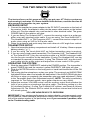
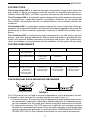
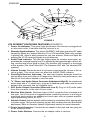
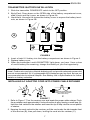
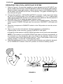
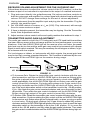
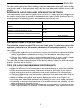
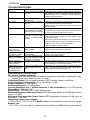
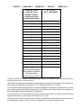
ENGLISH THE TWO MINUTE USER’S GUIDE 2:00 The instructions on this page will help you get your UT Series system up and running in minutes. For more detailed instructions, read the section of this manual that applies to your system. RECEIVER SETUP 1. Connect the supplied ac power adapter to the DC INPUT connector on the back of the receiver. Insert the adapter’s cable into the power cable retainer on the bottom of the unit. Plug the adapter into a wall socket or other electrical outlet. The green POWER light on the receiver will glow. 2. If you are using The Guitarist-UHF, connect the receiver output to a guitar amplifier using any standard guitar cable. If you are using The Vocal Artist-UHF, The Headset-UHF, or The Presenter-UHF, connect the receiver output to an audio mixer using an XLR to XLR audio cable. 3. Raise the antennas and point away from each other at a 45° angle from vertical. TRANSMITTER SETUP 1. Open the transmitter battery compartment and install a 9 V battery. Observe proper battery polarity (“+/–”). 2. If you are using The Vocal Artist-UHF, no further transmitter setup is required. 3. If you are using a body-pack transmitter (The Presenter-UHF, The Headset-UHF or The Guitarist-UHF), plug the microphone cable or a WA302 instrument cable into the four-pin connector on the transmitter (if using The Headset-UHF, see tag on headset for assembly instructions). If using The Guitarist-UHF, plug the instrument cable into the guitar output and adjust the volume control of the guitar. OPERATING THE SYSTEM 1. Slide the transmitter POWER/OFF switch to the POWER position. The transmitter’s green POWER light and the receiver’s yellow DIVERSITY A/B lights will glow. 2. Slide the MUTE/ON switch on the body-pack or hand-held transmitter to the ON position. 3. Talk or sing into the microphone, or play your guitar. The receiver’s red AUDIO PEAK light should flicker when loud sounds are transmitted. If the AUDIO PEAK light does not flicker or stays on constantly, the transmitter gain may need adjustment. (Refer to the Transmitter Audio Gain Adjustment section). NOTE: This step is particularly important for The Guitarist system, since guitar outputs can vary widely. 4. Adjust the receiver VOLUME control until the receiver output level matches the level of your guitar or microphone through a cable. (The factory setting is in the full clockwise position.) If using The Guitarist-UHF system, see Receiver Volume Adjustment for The Guitarist-UHF to match the receiver volume level to the level of a wired system. YOU ARE NOW READY TO PERFORM! IMPORTANT: Every wireless performance is a unique situation, and can present a variety of problems. Never attempt a performance without first conducting a “walkthrough” test on the wireless system in the performing area. If you encounter a problem, refer to the Troubleshooting table. 1 ENGLISH THANK YOU FOR CHOOSING SHURE Congratulations! You have purchased the finest wireless system in its class. Your Shure wireless system is engineered to provide a low-noise, high-quality sound comparable to other systems costing much more. Built in the tradition of reliability that has made Shure a symbol of American quality for more than half a century, this wireless system should provide you with excellent performance for years. To get the most out of your UT Series wireless system, please read the applicable section in this guide before you attempt to use the system. If you have any questions that are not answered in this booklet, please contact Shure Customer Service at (847) 866-2553, Monday through Friday, from 8:00 am to 4:30 pm, Central Standard Time. For technical data by fax, dial (800)488-3297 and follow the recorded instructions. Visit our website at www.shure.com for further information on this and other Shure products. INTRODUCTION Your new UT Series system is designed to give you the best of both sound reinforcement worlds: the freedom of a wireless system, and the reliability of world-famous Shure sound quality. This manual covers each of the UT Series systems: The Vocal Artist-UHF, The Presenter-UHF, The Headset-UHF, and The Guitarist-UHF. SYSTEM FEATURES All Shure UT Series systems offer a variety of of exceptional features, including: • Diversity Receivers with Exclusive Shure MARCAD Circuitry: MARCAD (MAximum Ratio Combining Audio Diversity) circuitry continuously processes the rf signal from each antenna and combines the audio outputs to produce one signal of optimum quality. The result is improved reception and exceptional freedom from dropouts. • Low-Traffic UHF Transmission: UT systems use a UHF (Ultra High Frequency) range between approximately 596 to 862 MHz (available frequencies depend on regulations in the country where the system is used). In urban areas, UHF frequencies are less congested than those in the VHF range, and are less susceptible to interference. • Multiple System Use: Up to eight UT systems can be used in the same performance space. Each system must be set at a different frequency. If systems are set to the same frequency, contact an authorized Shure dealer. NOTE: In multiple use situations, each transmitter must have a dedicated receiver. • Simultaneous Output Use: Unbalanced 1/4” phone plug and balanced XLR output connectors may be used simultaneously to different external devices. • Stackable and Rack-Mountable Receivers: If multiple systems are in use, receivers may either be stacked or rack-mounted, with two receivers fitting in the optional rack mount tray. In these situations, antennas should not touch or be crossed. (See Stacking and Rack-mounting Receivers.) • Range: UT Series transmitters will work at a distance of up to 100 meters (about 300 ft.) from the receiver. • Noise Squelch: The noise squelch circuit analyzes signal quality instead of signal strength, which allows the circuit to discriminate between noise and desired signal. This reduces the likelihood of noise burst due to environmental rf (radio frequency) noise. • Semi-Rigid Receiver Antennas: Three-inch rubberized antennas offer performance equal to telescoping antennas with added durability. • Low Battery Warning Light: A red light on the body-pack and hand-held transmitters warns the user that there is less than one hour of battery life left. 2 ENGLISH SYSTEM TYPES The Vocal Artist-UHF is a hand-held system designed for singers who desire the high quality of Shure microphones and the freedom of wireless performance. Includes a Shure BETA58 or SM58 dynamic microphone with a built-in transmitter. The Presenter-UHF is a body-pack system designed for public speakers who prefer an inconspicuous, hands-free lavalier microphone. Features an omnidirectional Shure WL93, supercardioid WL184, or cardioid WL185 micro-miniature lavalier microphone. The Headset-UHF is a body-pack system designed for users in physically active applications, who desire the freedom of hands-free microphone operation along with the performance of Shure wireless equipment. Features a WH20TQG headset microphone. The Guitarist-UHF is a body-pack system designed for use with electric guitars, basses, and other electric instruments. May be used with brass or woodwind instruments, with optional WM98 instrument microphone and mount. The Guitarist provides the freedom of going wireless and the reliability of high quality Shure sound. SYSTEM COMPONENTS Component The Vocal Artist-UHF Transmitter UT2 Hand-Held Microphone Transmitter Microphone* BETA58 SM58 or Hand-Held Microphone Receiver The Headset-UHF The Guitarist-UHF UT1 Body-Pack Transmitter WL93, WL184 or WL185 Lavalier Microphone — WH20TQG Headset Microphone UT4 Diversity Receiver with MARCAD Circuitry Power Supply Supplied Accessories The Presenter-UHF PS20 (120 Vac, 60 Hz) or PS20E (230 Vac, 50 Hz) Microphone Stand Adapter, Vinyl Transmitter Bag, Receiver Feet, Receiver VELCRO Mounting Strips Vinyl Transmitter Bag, Receiver Feet, Receiver VELCRO Mounting Strips Vinyl Transmitter Bag, Receiver Feet, Receiver VELCRO Mounting Strips Vinyl Transmitter Bag, Receiver Feet, Receiver VELCRO Mounting Strips *Additional microphones may be available at later date STACKING AND RACK-MOUNTING RECEIVERS SHURE SHURE SHURE STACKED RECEIVERS SHURE RACK-MOUNTED RECEIVERS FIGURE 1 The UT4 receiver may be used in numerous applications, and is designed to be easily stacked or rack-mounted for multiple system use (see Figure 1). • To stack receivers: The raised corners are designed to create stability when receivers are stacked, if placed on a flat surface with feet attached. It is important to position the antennas at a 45° angle from vertical so that the antennas do not touch. • To rack-mount receivers: The UT4 receiver is a half-rack unit, and two receivers should fit into a standard rack space. Place the outer antennas at a 45° angle from vertical; place the inner antennas in a vertical position. ANTENNAS SHOULD NOT CROSS OR TOUCH. (See Optional Accessories for rack mount accessories.) 3 ENGLISH 8 7 6 9 ÁÁÁ ÁÁ SHURE BOTHERS INC. UNBALANCED HIGH Z 5 . . 1 . . 2 3 4 EVANSTON IL 60202 USA UT4 DIVERSTIY RECEIVER DC INPUT 12–18 VDC LINE MIC 10 MIN MAX 11 .. .. . SQUELCH BALANCED LOW Z . FIGURE 2 . UT4 DIVERSITY RECEIVER FEATURES (FIGURE 2) 1. Power On Indicator: This green light glows when the receiver is plugged into an electrical outlet. It indicates that the receiver is on. 2. Diversity Signal Indicators: The yellow DIVERSITY A/B lights glow when RF (radio frequency) signals are received from the UT1 or UT2 transmitter. When only one light is glowing, the signal is being received on only one antenna. When both lights are glowing, the UT4 is receiving signals on both antennas. 3. Audio Peak Indicator: This red light flickers when the receiver input signal approaches the overload clipping level. It is affected by the transmitter gain control setting, and the level of the guitar or bass (The Guitarist-UHF systems) or the singer or the speaker (The Vocal Artist-UHF, The Presenter-UHF, and The Headset-UHF systems). 4. Volume Control: Rotate this knob to increase or decrease the volume of the receiver output. This control does not affect the AUDIO PEAK indicator. 5. Semi-Rigid Receiver Antennas: The semi-rigid receiver antennas should be pointed away from each other at 45° angle from vertical for best performance, and should not touch when stacked or rack-mounted. 6. 1/4” Phone Jack Audio Output Connector (Unbalanced High Z): An unbalanced audio cable with a 1/4” phone plug (such as a standard guitar cable) can be used between this connector and your amplifier input. 7. XLR Audio Output Connector (Balanced Low Z): Plug an XLR audio cable from this connector to the input of your mixer. 8. Mic/Line Slide Switch: Switches output of XLR connector from microphone to line level. Use of line level is suggested when connecting receiver to a mixing or amplifying device without an available mic-level input, such as a power amplifier, signal processing device or VCR. 9. Squelch Control: Adjusts squelch control setting to emphasize either signal quality or system range. This control is factory pre-set, and normally does not need further adjustment. Refer to Receiver Squelch Adjustment section for more information. 10.Power Input Connector: Connect the ac adapter to this jack and then plug into an ac electrical outlet. 11. Power Cable Retainer: Secures the ac adapter cable to receiver. 4 ÁÁÁÁ ÁÁÁÁ Á ÁÁÁÁ ÁÁ ÁÁÁÁ Á ÁÁÁ ÁÁÁÁ Á ÁÁÁÁ ÁÁ ÁÁÁÁÁ ÁÁ ÁÁÁÁ Á ÁÁÁ Á ÁÁÁÁ ÁÁÁ Á ÁÁ ÁÁÁÁ ÁÁÁ ÁÁÁÁ Á ÁÁ Á ÁÁÁÁ ÁÁÁÁÁ ÁÁÁÁ ÁÁÁ ÁÁÁÁ ÁÁÁÁ Á ÁÁÁÁ Á ÁÁ Á Á ÁÁÁÁÁÁÁÁÁ Á Á Á Á Á Á Á ÁÁ Á Á ÁÁÁÁÁÁ Á ÁÁÁÁÁ ÁÁ ENGLISH 9 8 11 10 7 LOW BATT ON 6 INPUT ATTEN 0 -20 OFF PWR MUTE 5 ÉÉÉ ÉÉ ÉÉ ÉÉÉ 1 4 2 3 FIGURE 3 UT1 BODY-PACK TRANSMITTER FEATURES (FIGURE 3) 1. Power/Off Switch: Turns transmitter power on and off. 2. Input Attenuation Switch: Allows choice between 0 dB and –20 dB attenuation, for greater range of audio gain control. 3. Power/Battery Fuel Gauge: The green light indicates the unit is on. The red light indicates less than one hour of battery life remains. 4. On/Mute Switch: Mutes the transmitter to prevent unwanted sounds from being picked up by the receiver without turning the transmitter off. 5. Input Connector: Miniature connector (TB4M) allows connection to a variety of lavalier and headset microphone cables and the Shure WA302 instrument adapter cable. 6. Belt Clip: Secures the transmitter to a belt, waistband or guitar strap. 7. Audio Gain Control: Provides audio level adjustment to accommodate various input signal strengths (e.g., speaking into a microphone or playing an instrument). The factory setting is at mid-point. A small screwdriver is supplied to make adjustments. 8. Antenna: A flexible wire antenna is permanently attached to the bottom of the UT1 body-pack transmitter. For best operation, the antenna must hang vertically, and should not be coiled or bundled. 9. Battery Compartment: Holds one 9 V battery. Hinged cover opens to provide access to the battery. 10. Lavalier Microphone (WL93 shown): Omnidirectional (WL93), supercardioid (WL184) or cardioid (WL185) condenser lavalier microphone, featuring a mount that clips onto a tie, lapel, or acoustic instrument and an attached Miniature Connector, TA4F (supplied with The Presenter system) 11. Headset Microphone (WH20TQG shown): Headset microphone features a headset frame, headband, and an attached Miniature Connector (TA4F). See tag attached to headset for assembly instructions (supplied with The Headset System). 5 ENGLISH ATTACHING THE UT1 BODY-PACK TRANSMITTER TO BELT OR GUITAR STRAP FIGURE 4 1. Depress the tab marked PRESS and slip your belt, waist band or guitar strap between the transmitter body and the belt clip (Figure 4). 2. The clip holds tighter if the material is drawn to the clip’s top wire, especially when using thinner guitar straps. UT2 MICROPHONE-TRANSMITTER FEATURES (FIGURE 5) 5 ÁÁÁ ÁÁÁ ÁÁÁ ÁÁÁ ÁÁ ÁÁ ÁÁ ÁÁ ÁÁ ÁÁ OFF PWR LOW 1 BAT ON MUTE 2 3 4 FIGURE 5 6 ÁÁÁÁ ÁÁÁ ÁÁÁÁ ÁÁÁÁÁ ÁÁÁÁ ÁÁÁ ÁÁ ÁÁÁÁÁ ÁÁÁÁ Á ÁÁÁ Á ÁÁÁ ÁÁ ÁÁ ÁÁÁÁÁ ÁÁÁÁ ÁÁÁ ÁÁÁ ÁÁ ÁÁ Á Á 7 1. Power/Off Switch: Turns the transmitter on and off. It is recessed to prevent it from being accidentally turned off. 2. Power On Indicator: Green light glows when the POWER/OFF switch is in the POWER position, as a reminder to turn the transmitter off when it is not in use. 3. Low Battery Indicator: A red light glows when there is one hour or less of useful operating time, allowing battery to be changed before power is depleted. 4. On/Mute Switch: Allows muting of the microphone audio, avoiding the “thump” noise that can occur when turning the transmitter on and off. 5. Audio Gain Control: Allows the level of vocals to be matched with the transmitter for better performance. 6. 9 V Battery (shown installed): Provides power to the microphone-transmitter. 7. Battery Cover: Unscrews for access to the 9 V battery and gain control. 6 ENGLISH TRANSMITTER BATTERY INSTALLATION 1. Slide the transmitter POWER/OFF switch to the OFF position. 2. Body-Pack: Press down on the OPEN side of the battery compartment cover, slide it back and flip it open, as shown in Figure 6A. 3. Hand-Held: Unscrew the transmitter battery cover to expose the battery terminals, as shown in Figure 6B. Á ÁÁÁÁ Á Á ÁÁÁ Á Á ÁÁÁ Á Á ÁÁ Á Á Á Á Á Á Á ÁÁ ÁÁ Á ÁÁÁÁÁ Á Á Á Á Á Á Á Á ÁÁÁÁ ÁÁÁ Á ÁÁ ÁÁ Á Á Á ÁÁÁ ÁÁ Á ÁÁÁÁ ÁÁ ÁÁ ÁÁÁÁ ÁÁÁÁ ÁÁÁ - + A B + FIGURE 6 4. Insert a fresh 9 V battery into the battery compartment as shown in Figure 6. 5. Replace battery cover. 6. When the transmitter’s red LOW BATTERY light glows, you have 1 hour or less of useful battery life remaining; change the battery at your first opportunity. IMPORTANT: 9 V Alkaline batteries are recommended. 9 V lithium batteries are optional. Carbon-zinc and zinc-chloride batteries will not provide adequate power and are not recommended. 8.4 V rechargeable NiCd batteries may be used, but are not recommended due to minimal lifespan. See Battery Life in Specifications for further details on battery selection. INSTALLING AC ADAPTOR CORD INTO POWER CABLE RETAINER AC POWER ADAPTER AND POWER CABLE RETAINER (BOTTOM VIEW) A C B FIGURE 7 1. Refer to Figure 7. Turn the receiver over and locate the power cable retainer. Pinch the ac adaptor cord approximately 6 inches from the dc plug, forming a small loop (A). Hold the cord vertical to the retainer and lower the tip of loop into the curved portion of retainer. 2. Keeping the cord vertical to the receiver, pull the cord under the tab towards front of the receiver (B), then pull down, locking the cord into the retainer (C). 7 ENGLISH OPERATING THE VOCAL ARTIST-UHF SYSTEM 1. Refer to Figure 8. Connect the supplied ac power adapter into the DC INPUT connector in back of the receiver. Insert the adapter’s cable into the power cable retainer. Plug the adapter into a wall socket or other ac power source (use PS20 for 120 Vac, 60 Hz power; use PS20E for 230 Vac, 50 Hz power). The green POWER light on the receiver will glow. 2. Connect the receiver’s XLR AUDIO OUTPUT connector to the mixer input using an XLR to XLR audio cable. If no XLR cable is available, a 1/4” to 1/4” phone plug cable may be substituted, but this connection will not be balanced. Set the receiver’s MIC/LINE SWITCH to match the sound system’s input. 3. Slide the transmitter’s POWER/OFF switch to the POWER position. The transmitter’s green POWER ON light and the receiver’s DIVERSITY A/B lights will glow. 4. Slide the microphone’s ON/MUTE switch to the ON position to turn the microphone on. 5. Talk or sing into the microphone. Normal operation is indicated by: • Steady glow of the receiver’s yellow DIVERSITY A/B lights. • Flickering of the receiver’s AUDIO PEAK light when loud sounds are transmitted. NOTE: If the receiver’s red AUDIO PEAK light does not flicker occasionally or is constantly on, the transmitter gain may need to be adjusted. Refer to the Transmitter Audio Gain Adjustment section. Then, If the system is still not operating properly, consult the Troubleshooting table. 6. When the performance is over, turn off the sound system and slide the transmitter’s POWER/OFF switch to the OFF position to conserve battery power. UT2 45° SHURE UT4 FRONT FIGURE 8 8 BACK ENGLISH OPERATING THE PRESENTER-UHF SYSTEM 1. Refer to Figure 9. Connect the supplied ac power adapter to the DC INPUT connector on the back of the receiver. Insert the adapter’s cable into the power cable retainer. Plug the adapter into a wall socket or other ac power source (use PS20 for 120 Vac, 60 Hz power; use PS20E for 230 Vac, 50 Hz power). The green POWER light on the receiver will glow. 2. Connect the receiver’s XLR AUDIO OUT connector to the mixer input using an XLR to XLR audio cable. If no XLR cable is available, a 1/4” to 1/4” phone plug cable may be substituted, but this connection will not be balanced. Set the receiver’s MIC/LINE SWITCH to match the sound system’s input. 3. Press the WL93, WL184 or WL185 lavalier microphone into the mounting clip and attach it to your garment. Do not cover the microphone with your clothing, and keep it approximately 8 to12 inches below your chin. See Figure 9. 4. Slide the recessed transmitter POWER/OFF switch to the POWER position. The transmitter’s green POWER ON light and the receiver’s yellow DIVERSITY A/B lights will glow. 5. Slide the transmitter’s MUTE/ON switch to the ON position. 6. Speak in your normal conversational voice. Proper operation is indicated by: • Steady glow of the receiver’s yellow DIVERSITY A/B lights. • Flickering of the receiver’s AUDIO PEAK light when you speak in a loud voice. NOTE: If the receiver’s red AUDIO PEAK light does not flicker occasionally or is constantly on, the transmitter gain may need to be adjusted. Refer to the Transmitter Audio Gain Adjustment section. If the system is still not operating properly, consult the Troubleshooting table. 7. When the presentation is over, turn off the sound system and slide the recessed transmitter POWER/OFF switch to the OFF position to conserve battery power. ÁÁ Á Á ÁÁ Á Á ÁÁÁ WL93 shown SHURE Á UT1 45° SHURE UT4 FRONT FIGURE 9 9 BACK ENGLISH OPERATING THE HEADSET-UHF SYSTEM 1. Refer to Figure 10. Connect the supplied ac power adapter to the DC INPUT connector on the back of the receiver. Insert the adapter’s cable into the power cable retainer. Plug the adapter into a wall socket or other ac power source (use PS20 for 120 Vac, 60 Hz power; use PS20E for 230 Vac, 50 Hz power). The green POWER light on the receiver will glow. 2. Connect the receiver’s XLR AUDIO OUT connector to the mixer input using an XLR to XLR audio cable. If no XLR cable is available, a 1/4” to 1/4” phone plug cable may be substituted, but this connection will not be balanced. Set the receiver’s MIC/LINE SWITCH to match the sound system’s input. 3. If using the headset for the first time, refer to the tag attached to the headset for assembly instructions. Adjust headband and place on head, as shown on tag. For best results, microphone should be placed 1/2” from side of mouth. 4. Slide the recessed transmitter’s POWER/OFF switch to the POWER position. The transmitter’s green POWER ON light and the receiver’s yellow DIVERSITY A/B lights will glow. 5. Slide the transmitter’s MUTE/ON switch to the ON position. 6. Speak in your normal conversational voice. Proper operation is indicated by: • Steady glow of the receiver’s yellow DIVERSITY A/B lights. • Flickering of the receiver’s AUDIO PEAK light when you speak in a loud voice. NOTE: If the receiver’s red AUDIO PEAK light does not flicker occasionally or is constantly on, the transmitter gain may need to be adjusted. Refer to the Transmitter Audio Gain Adjustment section. If the system is still not operating properly, consult the Troubleshooting table. 7. When headset is not in use, turn off sound system and slide the recessed transmitter POWER/OFF switch to the OFF position to conserve battery power. SHURE ÍÈÈ ÈÈ ÈÈ ÈÈ Á UT1 45° SHURE UT4 FRONT FIGURE 10 10 BACK ENGLISH OPERATING THE GUITARIST-UHF SYSTEM 1. Refer to Figure 11. Connect the supplied ac power adapter to the DC INPUT connector in back of the receiver. Insert the adapter’s cable into the power cable retainer. Plug the adapter into a wall socket or other ac power source (use PS20 for 120 Vac, 60 Hz power; use PS20E for 230 Vac, 50 Hz power). The green POWER light on the receiver will glow. 2. Connect the receiver’s 1/4” PHONE JACK AUDIO OUTPUT connector to the amplifier input, using a standard guitar cable. 3. Connect your guitar or bass to the transmitter input jack with a WA302 Instrument Adaptor. NOTE: The Guitarist-UHF system may also be used with woodwind and brass instruments with use of an optional WM98 miniature instrument microphone and a horn mount. See Optional Accessories for additional information. 4. Adjust the volume control on your guitar to desired level. To match wireless output to that of a wired system, see Receiver Volume Adjustment for the Guitarist. 5. Slide the transmitter’s POWER/OFF switch to the POWER position. The transmitter’s POWER ON light and the receiver’s DIVERSITY A/B lights will glow. 6. Slide the transmitter MUTE/ON switch to the ON position. 7. Play your guitar or bass. Normal operation is indicated by: • Steady glow of receiver’s yellow DIVERSITY A/B lights. • Flickering of the receiver’s AUDIO PEAK light when loud sounds are transmitted. NOTE: If the red AUDIO PEAK light does not flicker occasionally or is on constantly, the transmitter may need to be adjusted. Refer to the Transmitter Audio Gain Adjustment section. If the system is still not operating properly, consult the Troubleshooting table. 8. When the performance is over, turn off the amplifier and slide the recessed transmitter POWER/OFF switch to the OFF position to conserve battery power. SHURE Á UT1 45° SHURE UT4 ÌÌÌÌÌÌÌÌÌ ÌÌÌÌÌÌÌÌÌ ÌÌÌÌÌÌÌÌÌ FRONT FIGURE 11 11 BACK ENGLISH RECEIVER VOLUME ADJUSTMENT FOR THE GUITARIST-UHF Follow these directions to adjust the volume control of the UT4 receiver, so that the wireless output of an instrument is equivalent to the output of a cabled instrument. 1. Plug instrument directly into guitar/bass amp. Set volume and tone controls on both the instrument and amplifier for a clean signal with desired tonal quality and volume. DO NOT change these settings for the rest of volume adjustment. 2. Unplug instrument from the amplifier input and plug into the transmitter. Plug the receiver into amplifier input. 3. Set VOLUME control of receiver at 1/4 on (9:00). Play instrument, with enough force to cause maximum output. 4. If there is distortion present, the transmitter may be clipping. See the Transmitter Audio Gain Adjustment section. 5. Adjust receiver volume control until sound quality matches that achieved in step 1. TRANSMITTER AUDIO GAIN ADJUSTMENT The audio gain control on both the UT1 body-pack and UT2 hand-held transmitters has been factory-preset at the mid-range position for best performance in most applications. If the red AUDIO PEAK light on the receiver does not flicker, the preset gain level may be too low and the audio gain may need to be increased until a proper signal-to-noise ratio is reached. This may be necessary for soft singers or talkers, or guitar or basses with low outputs. For loud singers or talkers, or instruments with high outputs, the preset gain level may be too high, causing unwanted distortion. This condition is indicated by the continuous glow of the red PEAK light on the receiver during usage. ÁÁÁ ÁÁ ÁÁ Á Á ÁÁ ÁÁÁ Á Á ÁÁ Á ÁÁ Á Á Á Á ÁÁ Á ÁÁÁÁ ÁÁ ÁÁÁ ÁÁ ÁÁÁ + UT1 BODY-PACK TRANSMITTER • UT2 HAND-HELD TRANSMITTER FIGURE 12 To Increase Gain: Rotate the transmitter gain control clockwise with the supplied screwdriver until the red AUDIO PEAK light on the receiver flickers when the guitar is played loudly or when you sing or speak in a loud voice. NOTE: In some applications, the red AUDIO PEAK light will not flicker even with the gain control turned fully clockwise. For body-pack systems only: If gain control is rotated fully clockwise and the AUDIO PEAK light still does not flicker, check to see if the input attenuation switch on the transmitter is set to the –20 dB position. If it is, fully rotate the gain control counterclockwise, and move the switch to the 0 dB position. Then rotate the gain control clockwise until the AUDIO PEAK light flickers during high output or the gain control is turned fully clockwise. • To Reduce Gain: Rotate the transmitter gain control counterclockwise with the sup- plied screwdriver. Continue rotating the gain control until the red AUDIO PEAK light on the receiver only flickers when guitar is played loudly, or when you sing or speak in a loud voice. For body-pack systems only: If gain control is rotated fully counterclockwise and the AUDIO PEAK light still glows continuously, check to see if the input attenuation switch on the transmitter is set to the 0 dB position. If it is, move the switch to the –20 dB position, and fully rotate the gain control clockwise. Then rotate the gain control counterclockwise until the AUDIO PEAK light flickers during high output. 12 ENGLISH To return audio gain to the factory setting, rotate the transmitter audio gain control to the mid position and, on the body-pack only, slide the input attenuation switch to the 0 dB position. BODY-PACK AUDIO GAIN AND ATTENUATION SETTINGS The attenuation switch and the gain control on the UT1 body-pack are designed to be used in conjunction to provide a wide spectrum of gain control choices. The following ranges are starting points; actual output levels may vary. OUTPUT DEVICE ATTENUATION SWITCH SETTING AUDIO GAIN CONTROL SETTING LAVALIER MICROPHONE, CONVERSATIONAL VOICE 0 dB HIGH (clockwise) LAVALIER MICROPHONE, PROJECTED VOICE HEADSET, CONVERSATIONAL VOICE 0 dB MID–RANGE HEADSET, PROJECTED VOICE ELECTRIC GUITAR/BASS, PASSIVE ELECTRONICS 0 dB LOW (counterclockwise) ELECTRIC GUITAR/BASS, PASSIVE ELECTRONICS –20 dB HIGH (clockwise) ELECTRIC GUITAR/BASS, ACTIVE ELECTRONICS –20 dB MID–RANGE ELECTRIC GUITAR/BASS, ACTIVE ELECTRONICS –20 dB LOW (counterclockwise) RECEIVER SQUELCH ADJUSTMENT The squelch control on the UT4 receivers (see figure 1) is factory preset for optimum performance. No further adjustment is normally required. It is possible to adjust the squelch control setting to emphasize either signal quality or system range: • Turning the squelch control clockwise causes the receiver to demand a higher quality signal (less noise before muting), but decreases operating range. • Turning the squelch control counterclockwise allows a lower quality signal through (more noise before muting), but increases operating range. To return the receiver squelch control to the factory setting, rotate it to the mid-range position (so the slot is vertical). TIPS FOR ACHIEVING MAXIMUM PERFORMANCE • Make sure you can always see a receiver antenna from the transmitter position. • Keep the distance from transmitter to receiver antenna as short as possible. • Point receiver antennas away from each other at a 45° angle from vertical. • Avoid placing the receiver antennas near metal surfaces and obstructions. • To mount the receiver on a flat surface, attach the four adhesive rubber feet or the VELCRO mounting strips to the bottom of the receiver. • Monitor battery fuel gauge and replace battery as soon as red light is on. • Let body-pack transmitter antenna hang freely; do not coil or keep in pocket. • If stacking or rack mounting receivers in a multiple-system use situation, do not allow antennas to touch or cross. • Perform a walk-through before performance or presentation. If dead spots are found, adjust location of receiver. If dead spots remain, mark spots and avoid. 13 ENGLISH TROUBLESHOOTING INDICATOR STATUS SOLUTION No sound. PROBLEM Green transmitter POWER light off. No sound. Green transmitter POWER light glowing. Green receiver POWER light off. Slide transmitter POWER ON/OFF switch to ON position. Make sure battery is inserted properly, observing battery polarity (“+/–”). If battery is inserted properly, replace with fresh battery. Slide transmitter MUTE/ON switch to ON position. No sound. No sound. No sound. Receiver DIVERSITY A/B lights glowing. PEAK light flickers during loud sounds. Receiver DIVERSITY A/B lights off. Transmitter and receiver POWER lights glowing. Make sure ac adapter is securely plugged into electrical outlet and into dc input connector. Make sure ac electrical outlet works and supplies proper voltage. Turn up receiver volume control. Confirm that the output connections from the receiver to the external equipment are secure. Confirm transmitter’s and receiver’s frequencies match. Point receiver antennas away from each other at a 45° angle from vertical. Move receiver antennas away from any metal objects. Remove obstructions between transmitter and receiver. Sound level differs from level of a cabled instrument. Sound level differs with different guitars. Distortion level increases gradually. Bursts of noise or other audible radio signals present. Momentary loss of sound as transmitter is moved around performing area. Receiver DIVERSITY A/B lights glowing. Receiver DIVERSITY A/B lights glowing. Receiver DIVERSITY A/B lights and transmitter LOW BATTERY light glowing. DIVERSITY A/B lights on. Receiver DIVERSITY A/B lights off when sound is lost. Make sure you can see receiver antennas. Move transmitter closer to receiver. Adjust transmitter gain as necessary. Adjust receiver volume as necessary. Readjust transmitter gain level to compensate for differences in guitar outputs. Replace transmitter battery. Identify potential sources of interference (other RF sources) and turn off, remove or use a wireless system operating on a different frequency. Reposition receiver and perform walk-through test again. If audio dropouts persist, mark “dead” spots and avoid them during performance. SYSTEM SPECIFICATIONS RF Carrier Frequency Range Approximately 596 to 862 MHz (Available frequencies depend on applicable regulations in country where system is used). Operating Range:100 m (approximately 300 ft) under typical conditions Audio Frequency Response: 20 to 16,000 Hz, ±3 dB Image Rejection: 75 dB typical Spurious Rejection: 75 dB typical System Distortion (ref. ± 45 kHz deviation, 1 kHz modulation): 0.1% THD typical Signal/Noise Ratio: 90 dB Sensitivity: –110 dBm for 12 dB SINAD typical Maximum Recommended Input Level, UT1 (attenuation switch at –20 dB, gain at minimum): +32 dBV Minimum Recommended Input Level, UT1 (attenuation switch at 0 dB, gain at maximum): –80 dBV Operating Temperature Range –29° to 74° C (–20° to 165° F) NOTE: Battery characteristics may limit this range. Battery Life UT1, UT2: 12 hours with 9 V alkaline battery (Duracell MN1604 recommended). 14 ENGLISH UT1 BODY-PACK TRANSMITTER SPECIFICATIONS RF Output Input Configuration Connector Type Actual Impedance Connector Pin Assignments 15 mW Typical Unbalanced 4-pin Miniature connector (male), TB4M 1 MΩ Pin 1: Ground Pin 2: +5 V Bias Pin 3: Audio In Pin 4: 20kΩ Resistor to Audio Ground Dimensions 82.6 mm H x 63.5 mm W x 26.2 mm D (3.25” H x 2.50” W x 1.03” D) Net Weight 125g (4.4 oz.) including battery Power Requirements 9 V alkaline battery (Duracell MN1604 recommended); V lithium ULTRALIFE battery optional. Nominal Current Drain 40 mA 9 UT2 HAND-HELD TRANSMITTER SPECIFICATIONS RF Output Dimensions Net Weight Power Requirement Nominal Current Drain UT2/58 (SM58) UT2/(BETA58) 15 mW Typical 241 mm H x 51 mm D 241.3 mm H x 36.83 mm D (9.49” H x 2.01” D) (9.5” H x 1.45” D) 296g (10.4 oz.) 296g (10.4 oz.) 9 V alkaline battery (Duracell MN1604 recommended); 9 V lithium ULTRALIFE battery optional. 40 mA UT4 RECEIVER SPECIFICATIONS Connector Maximum Output Levels Nominal Output Levels Output Configuration Actual Impedance Connector Pin Assignments Dimensions Net Weight Power Requirements Power Supply Voltage/Current/Phantom Power Protection 3-Pin XLR (male) 1/4” phone plug (female) Line Level: +10 dBV +4 dBV Mic Level: –22 dBV Line Level: –26 dBV –32 dBV Mic Level: –62 dBV Active Balanced Unbalanced Line Level: 138 Ω 1 kΩ Mic Level: 500 Ω Pin 1: ground Tip: hot Pin 2: hot Sleeve: ground Pin 3: cold 41 mm H x 197 mm W x 138 mm D (1.625” H x 7.77” W x 5.42” D) 419.6g (14.8 oz.) 12–18 Vdc nominal, 200mA 120 V or 230V ac adaptor with 2.1 mm female plug Yes Yes 15 ENGLISH CERTIFICATION UT1: Type Accepted under FCC Part 74. Certified by IC in Canada under RSS–123. Conforms to European Union directives, eligible to bear CE marking; meets European Union Requirements. ETSI Type Approval: pr I–ETS 300 422, EMC Immunity: Meets Requirements of EMC Standard 301 489 Parts 1 and 9. UT2/BETA58, UT2/58: Type Accepted under FCC Part 74. Certified by IC in Canada under RSS–123. Conforms to European Union directives, eligible to bear CE marking; meets European Union Requirements. ETSI Type Approval: pr I–ETS 300 442, EMC Immunity: Meets Requirements of EMC Standard 301 489 Parts 1 and 9. UT4: Approved under the Notification provision of FCC Part 15. Certified by IC in Canada under RSS–123. Conforms to European Union directives, eligible to bear CE marking; meets European Union Requirements. EMC Immunity: Meets Requirements of EMC Standard 301 489 Parts 1 and 9. Power supply meets Low Voltage Directive: 73/23/EEC. Shure Models UT1 and UT2 Transmitters meet the essential requirements of the European R&TTE Directive 99/5/EC and are eligible to carry the CE marking. O682 Shure Model UT4 Receivers meet the essential requirements of the European R&TTE Directive 99/5/EC and are eligible to carry the CE marking. Power supply meets the following safety standard: PS20 Power Supply: UL 1310, CAN/CSA 22.2 No. 223. PS20E Power Supply: EN 60065/09.93. PS20J Power Supply: Meets DENTORI 91-49851 PS20UK Power Supply: EN 60065 5th, 1985. FURNISHED ACCESSORIES Screwdriver . . . . . . . . . . . . . . . . . . . . . . . . . . . . . . . . . . . . . . . . . . . . . . . . . . 65A1659 Mounting Block (The Presenter Systems Only) . . . . . . . . . . . . . . . . . . RK329MB* Single-Mount Tie Bar (The Presenter Systems Only) . . . . . . . . . . . . . RK240SB* Windscreen (The Presenter Systems Only) . . . . . . . . . . . . . . . . . . . . . RK242WS* Receiver AC Adapter . . . . . . . . . . . . . . . . . . . . . . . . PS20 (120V), PS20E (230V) Vinyl Transmitter Bag (Body-Pack Systems Only) . . . . . . . . . . . . . . . . . . . . 26A13 Vinyl Transmitter Bag (The Vocal Artist Systems Only) . . . . . . . . . . . . . . . 26A14 Carrying Case, plastic, black (UT2/BETA58) . . . . . . . . . . . . . . . . . . . . . . 94A8415 Swivel Adapter (The Vocal Artist Systems Only) . . . . . . . . . . . . . . . . . . . WA370A ∗ Replacements furnished in multiples of 4. OPTIONAL ACCESSORIES 1/4” to 1/4” Cable (The Guitarist-UHF only) . . . . . . . . . . . . . . . . . . . . . . . . WA303 1/4” to Miniature Connector (TA4F) Cable . . . . . . . . . . . . . . . . . . . . . . . . . WA302 1.8 Meter (6 ft.) Receiver-Mixer Cable . . . . . . . . . . . . . . . . . . . . . . . . . . . . . WA410 Rack Mount Tray . . . . . . . . . . . . . . . . . . . . . . . . . . . . . . . . . . . . . . . . . . . . . . . . . URT Nylon Carrying Case . . . . . . . . . . . . . . . . . . . . . . . . . . . . . . . . . . . . . . . . . . . WA590 Dual Tie Clip (The Presenter-UHF w/WL184, WL185 only) . . . . . . . . . RK183T2 Double Tie Clip (The Presenter-UHF w/WL93 only) . . . . . . . . . . . . . . . RK307DB Miniature Instrument Microphone (Body-Pack Systems only) . . . . . . . . . . WM98 Universal Horn Clamp (Body-Pack Systems only) . . . . . . . . . . . . . . . . . . A98KCS Miniature Instrument Microphone w/ Universal Horn Clamp . . . . . . . WM98KCS Rubber Receiver Feet (4) . . . . . . . . . . . . . . . . . . . . . . . . . . . . . . . . . . . . . . 66A8053 VELCRO Fastener, Hook (2) . . . . . . . . . . . . . . . . . . . . . . . . . . . . . . . . . . . . 80A8118 VELCRO Fastener, Loop (2) . . . . . . . . . . . . . . . . . . . . . . . . . . . . . . . . . . . . 80A8119 Amp/Powered Mixer Stand for UT4 Receiver . . . . . . . . . . . . . . . . . . . . . . . . WA595 Inline Audio Switch for UT1 Transmitter . . . . . . . . . . . . . . . . . . . . . . . . . . . WA360 For additional service or parts information, contact Shure’s Service department at 1–800–516–2525. Outside the U.S., contact an Authorized Shure Service Center. 16 ENGLISH THIS RADIO EQUIPMENT IS INTENDED FOR USE IN MUSICAL PROFESSIONAL ENTERTAINMENT AND SIMILAR APPLICATIONS. NOTE: THIS RADIO APPARATUS MAY BE CAPABLE OF OPERATING ON SOME FREQUENCIES NOT AUTHORIZED IN YOUR REGION. PLEASE CONTACT YOUR NATIONAL AUTHORITY TO OBTAIN INFORMATION ON AUTHORIZED FREQUENCIES FOR WIRELESS MICROPHONE PRODUCTS IN YOUR REGION VELCRO is a registered trademark of Velcro Industries B.V. Licensing: A ministerial license to operate this equipment may be required in certain areas. Consult your national authority for possible requirements. Shure Transmitters Models UT1 and UT2 may be used in the countries and frequency ranges listed in Table 1. LICENSING INFORMATION IMPORTANT: Licensing of Shure wireless microphone equipment is the user’s responsibility, and licensability depends on the user’s classification and application, and on the selected frequency. Shure strongly urges the user to contact the appropriate telecommunications authority concerning proper licensing, and before choosing and ordering frequencies. Changes or modifications not expressly approved by Shure Incorporated could void your authority to operate the equipment. Operation of this equipment is subject to the following two conditions: (1) this device may not cause interference and (2) this device must accept interference, including interference that may cause undesired operation of the device. WARRANTY INFORMATION Shure Incorporated (“Shure”) hereby warrants that these products are free from defects in material and workmanship for a period of one year from date of purchase, all transmitter and receiver parts. At its option, Shure will repair or replace the defective product and promptly return it to you. You should retain proof of purchase to validate the purchase date and return it with any warranty claim. If you believe this product is defective within the warranty period, carefully repack the unit, insure it, and return it postpaid to: Shure Incorporated Attention: Service Department 222 Hartrey Avenue Evanston, IL 60202-5730 U.S.A. Customers outside the U.S.A. should ship the product to the authorized Shure Distribution Center in their region. This warranty does not apply in cases of abuse or misuse of the product, use contrary to Shure’s instruction, or unauthorized repair. All implied WARRANTIES of MERCHANTABILITY or FITNESS FOR A PARTICULAR PURPOSE are hereby disclaimed and Shure hereby disclaims liability for incidental, special or consequential damages resulting from use or unavailability of this product. Some states do not allow limitations on how long an implied warranty lasts, or the exclusion or limitation of incidental or consequential damages, so the above limitation may not apply to you. This warranty gives you specific legal rights, and you may have other rights which vary from state to state. THIS WARRANTY SUPERSEDES ALL WARRANTIES THAT ARE INCLUDED WITH THIS PRODUCT. 17 TABLE 1 TABLEAU 1 TABELLE 1 TABLA 1 Country Code Code de Pays Lander–Kurzel Codigo de Pais Codice del Paese UT1, UT2 (595 – 865 MHZ) A 595 – 865 MHZ * B 595 – 865 MHZ * CH 595 – 865 MHZ * D 595 – 865 MHZ * E 595 – 865 MHZ * F * GB * GR 595 – 865 MHZ * TABELLA 1 I * IRL 595 – 865 MHZ * L 595 – 865 MHZ * NL 595 – 865 MHZ * P 595 – 865 MHZ * DK 800 – 820 MHZ* FIN 800,1 – 819,9 MHZ * N 800 – 820 MHZ* S 800 – 814 MHZ * All Other Countries Tous les autres pays Alle anderen Länder Demás países Tutti gli altri Paesi * *Please contact your national authority for information on available legal frequencies for your area and legal use of the equipment. *Se mettre en rapport avec les autorités compétentes pour obtenir les informations sur les fréquences autorisées disponibles localement et sur l’utilisation autorisée du matériel. *Für Informationen bezüglich der für Ihr Gebiet verfügbaren gesetzlich zugelassenen Frequenzen und der gesetzlichen Bestimmungen für den Einsatz der Geräte setzen Sie sich bitte mit der zuständigen örtlichen Behörde in Verbindung. * Comuníquese con la autoridad nacional para obtener información en cuanto a las frecuencias legales disponibles y usos legales del equipo en su área. *Rivolgersi alle autorità competenti per ottenere informazioni relative alle frequenze autorizzate nella propria regione e alle norme che regolano l’uso di questo apparecchio. Patent Notice: Des 404,736 Shure Incorporated 222 Hartrey Avenue Evanston, Illinois 60202–3696 Phone: 847–866–2200 Fax: 847–866–2279 Web Address: http://www.shure.com In Europe, Phone: 49–7131–72140 Fax: 49–7131–72141 Outside Europe and the U.S., Phone: 847–866–2200 27D8692 (BG) Fax: 847–866–2585 Copyright 2002, Shure Incorporated Printed in U.S.A.