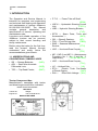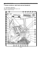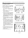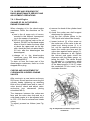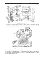
1
OPERATION AND SERVICE MANUAL BELARUS SERIES 80.1/80.2/82.1/82.2/82Р Eighth edition, revised and enlarged Publication No. Number of copies pcs. Language – English Released for print ATTENTION! IMPORTANT! 1. Make a thorough study of this Manual before operating a new tractor and follow the instructions given therein. 2. Use season-specific diesel fuels as specified in this Manual. 3. DO NOT run the diesel-engine in idling for more than 15 minutes. 4. Keep in mind that diesel-start-up is only possible with the gearbox lever in the extreme left-hand position (i.e. engagement position I or gear range position II). 5. When operating the tractor without using the rear P.T.O., set the driving pin of the P.T.O. independent two-speed drive to position I (540 r.p.m.), the lever of the P.T.O. independent synchromesh drive — to its neutral (midposition), and the control lever — to its "P.T.O. Disengaged" position (refer to Section «Controls»). 6. Rear P.T.O. syncronized drive should be used at speeds not exceeding 8 km/h. Otherwise, the tractor power train may suffer severe damages. 7. Run the tractor in 9th gear, with the higher gear range (range II) engaged, only. 8. A one-man seat is installed in the tractor’s cab; only operator should be in the cab. An additional passenger seat (option) can be installed on request. 9. Remove sealing film or cut off bosses from polyethylene plugs on new storage batteries. 10. DO NOT run the tractor with the transmission clutch engaged in full or partially. 11. When starting to move the tractor, first see to it that the parking brake is disengaged. 12. When operating the tractor without universal-joint shafts, set the FDA selector handle to the «force-engaged» position. 13. DO NOT operate the tractor in closed spaces, with lack of sufficient ventilation (interchange of air). Breathing the machine exhaust gases can harm or cause death. 14. NEVER tow tractors «Belarus» 82.1/82.2/82P with the front driving wheels raised above the ground. Violation of this rule can result in breakdown of the FDA drive and/or prevalence of emergency conditions. 15. DO NOT lift the tractor front end Запрещается поднимать переднюю часть трактора за передний буксир, который используйте только для буксировки. 16. NEVER start the diesel-engine and/or work on the tractor without storage batteries installed. 17. Tow or push start of the tractor diesel-engine may only be admitted as a last resort, lest intensive wear of diesel-engine parts should result. 18. Since Manufacturer, Production Enterprise «Minsk Tractor Works», pursues a policy of constant improvement of products, the design of, and/or operating instructions for, certain tractor assembly units and parts may incorporate modifications which have not been introduced in this Manual. Section 1. Introduction 2 1. INTRODUCTION The Operation and Service Manual is intended for operators and engineering and technical staff dealing with operation and maintenance of tractors «Belarus» 80.1/80.2/82.1/82.2/82Р. The Manual contains general description and specifications of tractors, operating and maintenance rules. Long-term and reliable operation of the «Belarus» tractors can be ensured, subject to their correct handling and timely maintenance. Before using the tractor for the first time, read the present Manual through, understand and strictly follow the recommendations given therein. 1.1. ABBREVIATIONS AND CONVENTIONAL SYMBOLS USED • SB — Storage Batteries; (АКБ); • ADL — Rear Axle Automatic Differential Lock; (АБД); • TDC — Top Dead Center; (ВМТ); Tractor Component Nos. Manufacturer’s nameplate with tractor and diesel-engine serial Nos. indicated MINSK TRACTOR WORKS BELARUS Tractor No. Weight Engine No. Year manufactured MADE IN BELARUS • P.T.O. — Power Take-off Shaft; (ВОМ) • HSCU — Hydrostatic Steering Control Unit; (ГОРУ); • HSB — Hydraulic Steering Booster; (ГУР); • SPTA — Spare Parts, Tools and Accessories; — (ЗИП); • GB — (Speed) Gearbox; (КП); • FDA — Front Driving Axle; (ПВМ); • SMS — Seasonal Maintenance Service; (СТО) • HDC — Haul-and-Draw Coupler; … (ТСУ) • MP-1, MP-2 and MP-3 —Maintenance Procedure No. 1, No. 2 and No. 3, respectively; (ТО №1,№2, №3) • HDC — Haul-and-Draw Coupler; (ТСУ); • UC —Unitized Cab; …………… (УК); • ETH— Electric Torch Pre-Heater of Diesel-Engine; (ЭФП) • RHL— Rear Hitch Linkage. (ЗНУ) Belarus 80.1/80.2/82.1/82.2/82Р/82Р — Operation and Service Manual Section 1. Introduction 3 Tractor Serial No. is duplicated on the on the front part of the right-hand sidemember (or on the right-hand plate of the front counterweights). Diesel-engine Serial No. is duplicated on the manufacturer’s nameplate attached to the cylinder block, on the right-hand side). Clutch No. (on the clutch housing, to the left). Gearbox No. (on the GB housing, to the left). Section 1. Introduction 4 Transmission No. (on the rear axle housing, in the rear). Front driving axle (on the FDA right-hand housing, at the front). Cab serial number Belarus 80.1/80.2/82.1/82.2/82Р —Operation and Service Manual Section 2.General Description and Technical Characteristics 5 2. GENERAL DESCRIPTION AND TECHNICAL CHARACTERISTICS OF TRACTORS Tractors Belarus are designed to perform a variety of farm jobs, in combination with different mounted, semi-mounted and trailer-type machinery and implements. Besides, tractors can be assigned to fulfill heavy-duty works when ganged up with earthmoving, shovel dredging, loading, post-hole digging implements; also, they can be used on transport missions and for driving various stationary farm outfits. Tractor Belarus 82Р is designed for an allround mechanization of growing rice and rotation of companion crops. All the technical facilities to be used in combination with Belarus tractors should be agreed with the Production Association «Minsk Tractor Works» (PA MTW). 2.1. TRACTOR DESIGN AND CONSTRUCTION IN BRIEF Wheeled tractors Belarus 80.1 (see Fig. 1), Belarus 80.2, Belarus 82.1 (рис. 2), and Belarus 82.2 are multipurpose agricultural machines, Class 1,4 tf (14 kN). These tractors differ from one another by the type of running gear: Belarus 80.1/80.2 – with one driving axle, Belarus 82.1/82.2 – with two driving axles. The tractors are of a semi-frame construction. Their skeleton consists of a semi-frame, housings of the clutch, change-speed gearbox and rear axle. The diesel-engine forepart is fastened on the front beam, while its aft-part is rigidly connected to the transmission clutch housing. Index .2 means a modernized version of the respective model, wherein one or several updated assemblies or units are installed, for example: • the front driving axle with planet-andspur reducing gearboxes (on tractors Belarus–82.2); • bonnet, cab roof, cab mudguards of a modified design (on tractors Belarus 80.2/82.2). Tractor Power Train incorporates a clutch, superreducer and speed gearbox, rear axle with automatic differential lock-up, and rear P.T.O. shaft with two-speed independent and synchronized drives. Tractors with two driving axles are equipped with a front driving axle (FDA) and drives — a transfer box, intermediate and front universaljoint shafts, and an intermediate bearing. The Tractor Steering Control can be of hydromechanical type (with a HSB body) or hydrostatic steering control type, with a metering pump (HSCU). The hydromechanical control outfit consists of a worm, quadrant and the hydraulic steering booster (HSB). The hydrostatic steering control unit (HSCU) incorporates a gerotor-type metering pump which is installed in the steering column on the front cab wall, diesel-engine driven feed gearpump, a hydraulic cylinder located in the steering trapezoid of the front driving axle (tractors Belarus 82.1/82.2) or tractor fore (non driving) axle (Belarus 80.1/80.2). The HSCU is fed with oil from the hydraulic hitch linkage system tank. Tractors with installed HSCU unit feature a hydraulic drive of the rear-axle differential lock-up unit, whose control cock is located under the slanted footboard of the cab. Locking action is effected by pressing the pedal located to the left of the service brake pedals. The FDA Drive is effected from the speedchange GB to ensure synchronized rotation of the front and rear wheels in any gear selected. The front driving axle is pivoted to the fore beam, thus, ensuring its free rolling motions. Provision is made for stepless adjustment of the front (for tractors equipped with a HSB) and rear wheels track. To implove tyre traction performance, as well as tractor steerability, additional counterweights can be mounted on the fore-beam totaling to 220 or 510 кг. Section 2.General Description and Technical Characteristics Belarus 80.1/80.2/82.1/82.2/82Р — Operation and Service Manual 6 Fig. 1. Tractor «Belarus» 80.1 Fig. 2. Tractor «Belarus» 82.1 Belarus 80.1/80.2/82.1/82.2/82Р — Operation and Service Manual Section 2. General description and technical characteristics 7 The tractor Belarus 82 P, intended for work on rice-growing fields, features increased ground clearance and, also, by a modified propulsion gear – wide crosssection low-pressure tyres, with welldeveloped (scalloped) lugs and lowprofile tread pattern. An increased ground clearance is achieved through installation of an additional hub drive, as well as the use of tyres of larger diameters. The rice-field tractor is equipped with a FDA control and parking brake interlocking mechanism. The Tractor Hitch Linkage System incorporates a hydraulic system and a rear hitch linkage. The hydraulic system comprises an oil pump, distributor, draft control, rear and external hydraulic cylinders. Tractor may be shipped as equipped with a draft (position) control system or without this system. The Rear Hitch Linkage is a four-link mechanism, with length-adjustable drop links. A RHL fixing mechanism is provided to hold mounted implements at the extreme upper position on transport missions. When running with trailed machines, a cross-bar with a hitch yoke can be used, while on transport missions — install a towing arrangement with a self coupling device and a hydraulic pick-up hook. Трактор оборудован пневматической системой управления тормозами прицепов с пневматическим или гидравлическим приводом тормозов. Electrical Equipment — d.c., 12 V rated voltage. Tractor (Unitized) Cab is a safety sealed frame-and-panel structure, equipped with a single torsion seat, adjustable to operator’s height and weight. An additional seat (option) can be installed. Cab windows are safety heat-absorbing monolithic glass. The cab is furnished with a heating and airventilation system, a dome light, windscreen wipers, sun visor, rear-view mirror. Natural ventilation of the cab is achieved through opened sunroof, rear and side windows. Provision is made for the change of angle of the steering wheel column within 15 deg., as a matter of convenience when entering and leaving the cab or operating the tractor, as well as for height adjustment within 100 mm. Also provided is a three-step sideboard and handrails. Installation of a unitized cab is paralleled with installation of a small-size cab on certain tractor batches, against a separate order. The diesel-engine cover is attached to the radiator grille facing frame by hinges; in its open position it is fixed with an arresting catch. On a separate order, the tractor may be supplied with optional extras: a drive pulley, side P.T.O., rear P.T.O. shaft replaceable tail-end (21 splines), reverse-reducer, additional counterweights, P.T.O.-2 tail-end guard, wheels with 18,4L-30; 9,5-42 tyres, starting pre-heater, automatic coupler СА1, hydraulic pick-up hook (ТСУ-2), pneumatic adapter, a cross-bar of the coupling device (ТСУ-1-Ж), device ТСУ-З-К (hauland-draw coupler arrangement), breakaway couplings with bracket, coupling hoses, left-hand adjustable drop link, auxiliary spacer-ring piece for mounting rear wheels, first aid kit, additional seat, and others. Besides, the tractor can be equipped with a travel speed superreducer which is purchased separately by the user, on his own. Also, the tractor should be equipped with a gearbox suitable for installation of the speed superreducer. The left-hand cab door can be locked. To open the door-lock from the outside: • insert a provided key 1 (Fig. 2а) into the slot in the barrel 2 of the handle; A synchronized reverse-reducer is installed at the Manufacturing Works (option), instead of a downshift reducing gear box, and help quickly reverse the tractor in any gear (ir = -1,07). Section 2. General description and technical characteristics Belarus 80.1/80.2/82.1/82.2/82Р — Operation and Service Manual 8 • turn the key to the «Open» position, without depressing the barrel, and open the door. To close and latch the door, turn the key to the «Closed» position, without depressing the barrel. Fig. 2а. 2.2. BASIC SPECIFICATIONS Tractor Overall Dimensions In Figure: Б = B; В = C; Г = D; Д = E; Е = F Description A Length, mm: Total w/o load over wheels B Width, mm C Height to cab top, mm D Wheelbase, mm E Rear wheeltrack, mm F Front wheeltrack, mm G Ground clearance, mm 80.1 80.2 82.1 (с ГУР) 82.2 82 Р 4120 3840 3650 1970 2780 2390 1400/2100 1450/1850 465 4120 3840 3650 1970 2800 2390 1400/2100 1450/1850 465 4120 3930 3740 1970 2800 2450 1350/2050* 1430/1990 465 4120 3970 3820 1970 2820 2440 1500/2100 1420/2000 465 4120 4020 3810 2370 3030 2450 1900 1900 715 * 1410/1970 mm - for tractor Belarus 82.1 equipped with a hydrostatic steering control Unit (HSCU). Belarus 80.1/80.2/82.1/82.2/82Р — Operation and Service Manual Section 2. General description and technical characteristics 9 Table 1 Unit of measurement Description Value GENERAL DATA Tractor type — Wheeled, universal, Class 1,4 tf Tractor make — Belarus Tractor model — Belarus 80.1/80.2 Belarus 82.1/82.2 Belarus 82Р Rated speed with downshift reducing gear disengaged, in: 1st gear 2nd gear km/h km/h 2,50 4,26 2,71 4,61 3rd gear km/h 7,25 7,84 4th gear km/h 8,90 9,63 5 gear 6th gear km/h km/h 10,54 12,34 11,41 13,34 7th gear km/h 15,16 16,40 8 gear 9th gear km/h km/h 17,95 33,39 19,40 — Reverse I km/h 5,27 5,69 Reverse II km/h 8,97 9,71 km/h 1,89 2,05 2 gear 3rd gear km/h km/h 3,22 5,48 3,49 5,93 4th gear th th Rated speed with downshift reducing gear engaged, in: 1st gear nd km/h 6,73 7,28 th km/h 7,97 8,63 th 6 gear 7th gear km/h km/h 9,33 11,47 10,10 12,40 8th gear km/h 13,58 14,69 9th gear km/h km/h 25,25 3,98 27,33 4,31 km/h 6,78 7,34 5 gear Reverse I Reverse II Least turning radius between kerbs, 1400 mm wheeltrack, with the inner rear wheel braked slightly: Belarus 80.1 Belarus 82.1/82.2 Belarus 82Р m m m 3,8 4,1 4,3 Belarus 80.1/80.2/82.1/82.2/82Р — Operation and Service Manual Section 2. General description and technical characteristics 10 Table 1, continued Description Maximum weight of towed trailer (on paved and unsurfaced roads of average quality) Weight of tractor: running: Belarus 80.1 Belarus 80.2 Belarus 82.1 Belarus 82.2 Belarus 82Р as shipped ex-works: Belarus 80.1 Belarus 80.2 Belarus 82.1 Belarus 82.2 Belarus 82Р Angles of gradientа (downgrade) for tractor on dry ground without turf cover: w/o trailer w/trailer Fording: Belarus 80.1/82.1/82.2 Belarus 82Р Temperature limits permissible for tractor operation Unit of measurement Value kg 12000 kg kg kg kg kg 3770 3770 4000 4100 ± 100 4420 ± 120 kg kg kg kg kg 3620 ± 100 3620 ± 100 3850 ± 100 3950 ± 100 4395 ± 120 deg. deg. 20 12 m m 0,85 1,0 °С ± 40 DIESEL-ENGINE Type — Model designation — Four-stroke, with (fuel) direct injection dieselengine Д-243 h.p. (kW) 78+5 (57,4+3,7) r.p.m. 2200 Fuel injection advance angle to dieselengine piston TDC (determined by meniscus method) deg. 20±1 Number of cylinders Cylinder diameter pcs mm 4 110 Piston stroke mm 125 — 16 l 4,75 — 1-3-4-2 Power rating Crankshaft rated rotational speed Compression ratio Cylinder swept volume Firing sequence Belarus 80.1/80.2/82.1/82.2/82Р — Operation and Service Manual Section 2. General description and technical characteristics 11 Table 1, continued Unit of measurement Description Value Cooling system — Fluid, closed, with coolant forced circulation Lubrication system — Combination type, with oil radiator — — Four-spool, in-line, with booster pump 4УТНИ Speed governor — Mechanical, all-speed, with fuel charge corrector Injector nozzle — Fuel pump насос Type Make 17.1112010-10, 171.1112010-01 220 – 228 (21,6 – 22,4) 2 Fuel injection pressure kgf/cm (MPa) — Air cleaner Starting system Weight of dry diesel-engine, less clutch Combination type, with dry centrifugal and inertia-contact oil bath cleaning Electric starter, electric torch pre-heater Kg 430 Fuels and Coolants To Be Used Fuel grade: Diesel fuel, main: in summer – grade Л-0,2-40 or Л-0,2-62 GOST 305-82, of first and A quality; in winter – grade З-0,2-35 or З-0,2-45 GOST 305-82, of first and A quality. Diesel fuel, equivalent: in summer – grade Л-0,5-40 or Л-0,5-62 GOST 305-82; in winter – grade З-0,5-35 or З-0,5-45 GOST 305-82. At -50°С: main – grade А-0,2 GOST 305-82, of first and A quality; equivalent – grade А-0,4 GOST 305-82. Coolant: main – ОЖ-40 или ОЖ-65 GOST 28084-89; equivalent – Tosol А 40М or Tosol А 65М Std. Specs. ТУ 6-57-48-91. POWER TRANSMISSION Clutch — Friction, single dry plate, spring-loaded type Downshift reducing gear — Two pairs of spur gears, doubling the number of gears Gearbox — Mechanical type, 9F+2R, multiple-speed sliding gearbox Belarus 80.1/80.2/82.1/82.2/82Р — Operation and Service Manual Section 2. General description and technical characteristics 12 Table 1, continued Unit of measurement Value Forward — 18 Reverse — 4 Forward — 17 Reverse — 4 Description Number of transmission gears: Belarus 82Р Main drive — A pair of spiral bevel gears Rear axle differential — Bevel, with four pinions Rear axle differential lock-up mechanism — Friction clutch, sensor controlled Final drives — Spur gears — Three spur gears Brakes — Dry disk-type Parking brake — Dry disk-type, independent Auxiliary hub transmission reducing gearbox on rear axle: Belarus 82Р FRAMEWORK, RUNNING GEAR Tractor framework Propulsion gear type Belarus 80. Belarus 82.1, Belarus 82.2, Belarus 82Р Tyres standard sizes: — Semi-frame type — Wheels on pneumatic tyres; rear driving wheels, front directive wheels — Wheels on pneumatic tyres; rear driving wheels, front driving and directive wheels Front wheels: Belarus 80.1 inch 9-20 Belarus 82.1 inch 11,2-20 Belarus 82.2 inch 360/70R24 Belarus 82Р inch 16,0-20 Belarus 80.1 inch 15,5R38 Belarus 82.1 inch 15,5R38 Belarus 82.2 inch 18,4R34 (Ф-11) Belarus 82Р inch 18,4R34 (Ф-44) Rear wheels колес: Belarus 80.1/80.2/82.1/82.2/82Р — Operation and Service Manual Section 2. General description and technical characteristics 13 Table 1, continued Unit of measurement Value Belarus 80.1/80.2 kgf/cm2 (MPa) 1,2 – 2,6 (0,12 – 0,26) Belarus 82.1 kgf/cm2 (MPa) 1,0 – 2,1 (0,10 – 0,21) Belarus 82.2 kgf/cm2 (MPa) 0,8-1,6 (0,08-0,16) Belarus 82Р kgf/cm2 (MPa) 0,8 – 1,7 (0,08 – 0,17) Rear wheels kgf/cm2 (MPa) 1,0 – 1,8 (0,10 – 0,18) Rear Wheels, tractor Belarus 82Р kgf/cm2 (MPa) 1,0 – 1,4 (0,10 – 0,14) Description Inflation pressure in tyres (depending on load) Front wheels: HYDRAULIC STEERING BOOSTER (HSB) Hydraulic booster type — Hydromechanical Steering control mechanism — Worm, spiral gear quadrant and HSB — Gear-type НШ10-В-3-Л Pump type Pump output l/min 21 Belarus 80.1/82.1 kgf/cm2 (MPa) 90–0,5 (9,0–0,05) Belarus 82Р kgf/cm2 (MPa) 100 ± 5,0 (10 ± 0,5) Maximum working pressure in the system: HYDROSTATIC STEERING CONTROL UNIT WITH A CYLINDER IN THE STEERING TRAPEZOID Metering pump — Gerotor, with delivery constant 100 cm3/rev. (160 cm3/rev.)* Safety valve working pressure, to be tuned to kgf/cm2 (MPa) 140+15 (14+1,5) Impact valve working pressure, to be tuned to kgf/cm2 (MPa) 200+20 (20+2,0) Feed pump — Pump deliver 21 l/min (28 l/min)* Turn mechanism — Double-acting hydraulic cylinder Cylinder diameter mm 50 (63)* Rod diameter mm 25 (30)* Rod distance mm 200 — Spool-type kgf/cm2 11,0 ± 2,0 (1,10 ± 0,20) Rear axle differential lock-up cock Working pressure of reducing valve, to be tuned to (MPa) __________________________________________________________ * With FDA equipped with planet-and-spur reducing gearboxes. Belarus 80.1/80.2/82.1/82.2/82Р — Operation and Service Manual Section 2. General description and technical characteristics 14 Table 1, continued Unit of measurement Description Value HYDRAULIC LIFT SYSTEM Type of hydraulic system — Universal, sectionalized-modular system 2 Давление срабатывания предохраниkgс/см 200–20 тельного клапана (МПа) (20–2,0) 2 Номинальное рабочее давление в систе- kgс/см 160 ме (МПа) (16) Pump — Gear-type НШ32А-3 or НШ32М-3, clockwise rotation Pump drive — From diesel-engine through P.T.O. drive pinions Pump delivery, not less than l/min 45 Distributor — Золотниково-клапанный, Р80-3/4-222/111 для тракторов с силовым регулятором, Р803/1-222 для тракторов без силового регулятора Cylinder — Double-action Ц100х200-3 Rear lift system capacity at 610 mm from the hitch axis, with drop links at additional kN(kgf) 18 (1800) holes, not less than Draft (position) control — Automatic, with movable operable sleeve and follow-up spool (sliding valve) ELECTRICAL EQUIPMENT, CONTROL AND MEASURING INSTRUMENTS Система проводки — Circuit rated voltage Current source В — Lightening and light warning system — Single-wire, supply source negative terminal is connected to “frame” 12 1150 W a.c. alternator, with a built-in integrated rectifier-regulator, two 12-V, 88 A•h storage batteries, connected in parallel. Two headlights of a “European Beam” type, with passing and driving beams; working floodlights (two front and two rear) to illuminate the work area; front two-section lights to indicate overall dimensions and turn; tail three-section lights to indicate the direction of turning, to signal braking (stop) and overall dimensions; a number-plate light, light-reflectors; warning light clusters signaling direction indicators are ON, hand parking brake is applied; cab dome light is ON; tractor-and-trailer lights (three pieces). Belarus 80.1/80.2/82.1/82.2/82Р — Operation and Service Manual Section 2. General description and technical characteristics 15 Table 1, continued Unit of measurement Description Value System of emergency audible signaling (for tractors equipped with an instrument cluster) Buzzer (when oil pressure drops below the permissible limit or coolant temperature rises above the permissible limit)/ Control and measuring instruments Oil pressure gauge in the diesel-engine lubrication system; Air pressure gauge in the pneumatic system; Diesel-engine coolant gauge; Voltage indicator; Fuel level indicator; Electric tachospeedometer with a built-in diesel-engine motometer in astronomic time units. It is possible to install an instrument cluster. Warning lights: air-cleaner blocking, emergency drop in oil pressure in diesel-engine, HSCU, airpressure in the pneumatic system, emergency coolant temperature in diesel-engine, glower plugs operation control. Without funnel Horn Combination type Plug-in socket to connect trailer’s electrical equipment and inspection lamp Heater fan electric motor Power 90 W Electric wipers frontshield Pantographic, single-brush rear screen Single-arm, singlebrush Frontshield washer Single spray-nozzle REAR POWER TAKE-OFF SHAFT Drive — Independent I, independent II, synchronized P.T.O. shaft rotational speed, with the drive position: independent I r.p.m. 540 independent II r.p.m. 1000 rev./m 3,5 synchronized: Belarus 80.1 Belarus 82.1/82.2 travel distance Belarus 82Р rev./m 3,6 travel distance Replaceable tail-end, number of splines — 8 and 21 Belarus 80.1/80.2/82.1/82.2/82Р — Operation and Service Manual Section 2. General description and technical characteristics 16 Table 1, continued Unit of measurement Description Type Value REAR HITCH LINKAGE FIXING MECHANISM — Mechanical TRAILER BRAKES CONTROL DRIVE Pneumatic, single-line, interlocked with tractor Type — brakes 2 Pneumatic system pressure maintained by a kgf/cm from 6,5 to 8,0 regulator (MPa) (from 0,65 to 0,80) Pressure in the pneumatic system limited by a kgf/cm2 8,5 – 10,0 relief valve (MPa) (0,85 – 1,00) OPTIONAL EXTRAS (DELIVERED ON REQUEST AT EXTRA PRICE) Drive pulley: • pulley mechanism — Bevel reduction gearbox • diameter mm 300 • width mm 200 • drive — From rear P.T.O. shaft Pulley rotational speed, with control levers position: 859 independent I r.p.m. independent II Side power take-off shaft: • drive Rotational speed at rated diesel-engine duty: • w/o downshift reducing gearing • with downshift reducing gearing Wheels with tyres: tyre type – rear Purpose r.p.m. 1590 — Dependent on the gearbox r.p.m. 754 r.p.m. 570 — — Pneumatic, low-pressure 18,4R30 or 18,4L–30 (18,4/78-30) for road-building and other specialized operations. 9,5–42 for row-crop jobs in narrow row spacing; 16,9R38 for row-crop jobs, larger-section mm 48 Haul-and-draw arrangement ТСУ-3К hook jaw width Position of towing hook relative ground: • position I • положение II Haul-and-draw arrangement ТСУ-1Ж Vertical load on hitch yoke, not more than Possible displacement of hitch point in horizontal plane, to either side from midposition in vertical plane from ground For tractor Belarus 82Р mm 775 mm 950 — To gang up with trailer-type machinery kgf (кN) 650 (6,5) mm mm mm up to 160 mm, at 80-mm intervals 200 – 500 (steplessly) 455 – 755 (steplessly) Belarus 80.1/80.2/82.1/82.2/82Р — Operation and Service Manual Section 2. General description and technical characteristics 8 Table 1, continued Description Unit of measurement Value Hydraulic hook (device ТСУ-2) — Type Rigid, with mechanical fixing in transport position, controlled by the tractor hydraulic system Vertical trailer-induced load on the hook, not more than kgf (kN) 1400 (14) Nominal distance when in transport position, from hook axis: • to P.T.O. shaft axis mm 217 • to P.T.O. shaft end-face mm 160 Hook jaw mm 55 Trailer pole loop inner diameter mm 70 Automatic coupler Type — СА-1 Break-away couplings in assy with bracket — To protect hoses rupture under axial forces (purpose) applied. Coupling hoses (purpose) — To couple hydraulic system of the tractor and that of agricultural machines. Travel speed superreducer — Mechanical type МХУ-0,5; hydromechanical type ГХУ-0,5 (to be provided by the user) Starting pre-heater — Steam-liquid type ПЖБ-200Г Additional counterweights, front-mounted pcs 10 • weight of one counterweight kg 20 or 45 Pneumoadaptor — For driving trailer hydraulic brakes. Rear P.T.O. shaft replaceable tail-end Rear P.T.O. taol-enf guard Auxiliary spacer-ring piece for rear wheel twinning FRONT DRIVING AXLE FOR TRACTORS МТW-82.1/82.2, МТW-82Р Drive — Main drive Differential — — Final drives — Propeller shafts — Transfer box — Freewheeling clutch lock-up and clutch disengagement mechanism Intermediate bearing — From transfer box, by two propeller shaft through an intermediate bearing. A pair of bevel gears, with spiral teeth Bevel gearing, self-locking, with a differential spider and friction clutches. Wheel-hub transmission with two bevel gear pairs *) Universal joints, splined to the intermediate bearing. Reducing gearing with spur gears and a freewheeling clutch. Movable clutch gear — With two sliding flanges and a safety clutch. ____________________________________________________________________ *) Epicyclic spur reducing gearboxes of wheel-hub transmissions – for tractors Belarus 82.2. Section 3. Safety Requirements Belarus 80.1/80.2/82.1/82.2/82Р — Operation and Service Manual 18 3. SAFETY REQUIREMENTS 3.1. GENERAL PROVISIONS 3.1.1. 3.1.2. Close observance of safety requirements ensures longer useful life and safe operation of the tractor. Only persons not younger than 17, holders of a tractor driving license, who have been briefed on accident and fire prevention, may be admitted to run the tractor. ATTENTION! 3.1.3. The shift time utilization factor should not exceed 0,7. It means that the shift time consists of the time of tractor operation proper plus the time for daily (intershift) maintenance, preparation and termination of works, tunning-up and adjustment, removing troubles detected, idle trips to operation sites, and time for rest. 3.3.3. 3.3.4. 3.3.5. 3.3.6. 3.4. SAFETY REGULATIONS WHEN RUNNING THE TRACTOR 3.4.1. 3.2. INSTRUCTIONS FOR TRANSPORTATION AND DE-PRESERVATION 3.2.1. 3.2.2. During tractor transportation and handling, be sure to follow the requirements specified under subsection 6.9.14. On depreservation of the tractor an/or auxiliary equipment, follow fire prevention instructions, as well as sanitary requirements when dealing with chemical agents and goods, cleaning cloth, rag wastes and oiled paper. 3.4.2. 3.4.3. 3.4.4. 3.3. REQUIREMENTS ON TRACTOR OPERABLE CONDITION 3.3.1. 3.3.2. The tractor should be run in properly, in accordance with the instructions under 5.3. The tractor should have no missing parts and serviceable. DO NOT allow dismantling of design-stipulated protective enclosures and/or safeguards from the tractor, as well as other parts and/or assembly units which affect its safe operation (the locking mechanism of the GB 9th gear, rear P.T.O. enclosure, and others). The technical condition of the braking system, steering controls and running gear should conform to safety requirements of relevant standards and the present Manual. Tractor controls should demonstrate positive locking in their operative positions. No leaks of electrolyte, water, fuel and/or oil can be admitted. 3.4.5. DO NOT carry passengers. (When the tractor is equipped with an unitized cab, a passenger in the machine is admissible, if an additional seat is installed). NEVER work on a tractor with defective measuring and/or control devices and gauges. DO NOT admit smoking of the diesel-engine or substantial drop in r.p.m. due to overload. On emergency and/or excessive increase in diesel-engine crankshaft r.p.m., cut off fuel feed immediately and pull the dieselengine emergency stop knob towards yourself. Independent drive of the rear P.T.O. should be engaged only on an out-of-operation dieselengine; while the synchronous drive — when the transmission clutch is disengaged. Belarus 80.1/80.2/82.1/82.2/82Р — Operation and Service Manual Section 3. Safety Requirements 19 3.4.6. 3.4.7. 3.4.8. 3.4.9. 3.4.10. 3.4.11. 3.4.12. 3.4.13. When operating the tractor with the rear P.T.O. shaft not in use, set the drive stem and the control lever in the neutral and the disengaged positions, respectively With a hauling device installed, DO NOT use the rear hitch linkage outfit. Lock the СА-1А automatic coupler dog by means of a spring split cotter. With a P.T.O.-driven machine detached from the tractor, remove the universal-joint shaft and close the P.T.O. tail-piece with the hood. Under no circumstances drop implements by setting the distributor lever or the draft control arm into the position "Forced Drop". Before starting the diesel engine, throw the GB shift lever to its extreme left-hand position. Check to see that the tractor, under it, as well as between the tractor and the implement attached and the area around it are clear of people during the start-up. Before getting the tractor moving, make sure that the reserve parking brake is disengaged, apply an audible signal and start moving smoothly. When on hauling jobs, be sure to use the sear belts (to be supplied on request). Whist coupling to the tractor or mounting an farm machines/implements, the coupler should be at a safe distance, until a complete standstill of the tractor. Coupling (mounting) procedure shall be initiated only by the operator’s signal. Shift gears with the clutch fully disengaged and at a low rotational speed of the diesel-engine crankshaft, only. 3.4.14. If a fault is detected, stop the tractor immediately and remove the fault. 3.4.15. With the tractor combined with farm machines and implements, be sure to comply, in addition, with the safety requirements for using these machines/ implements. 3.4.16. When moving to another field with the implements raised in transport position, make use of the rear hitch linkage locking mechanism. 3.4.17. A mounted machine/implement shall only be lowered to the working position after the aggregate has completed the turn, and raised before the turn is made. CAUTION! To avoid damage or breakage of the rear hitch linkage system, DO NOT turn the tractor aggregate if the tools of the attached implement are buried into the soil. 3.4.18. When tractor-mounted aggregates are running in a column, intervals between them must be as least 30 m. 3.4.19. When operating a tractor Belarus 82Р, before entering a check plot flooded with water, first shift the transfer box control rod rest to the «P.T.O. Forced Engagement» position, to ensure safe descent across the slope. 3.4.20. When running the tractor in the dark, make use of operable and switched ON illumination devices. 3.4.21. Cleaning, lubrication and repair jobs on the tractor should only be initiated with the diesel-engine completely stopped and the P.T.O fully disengaged. Section 3. Safety Requirements Belarus 80.1/80.2/82.1/82.2/82Р — Operation and Service Manual 20 3.4.22. If you need to leave operator’s seat, stop the tractor, throw the gearbox lever to the neutral, apply the reserve parking brake, with the brake pedals interlocked. 3.4.23. Running the tractor across slopes of up to 9° steep should be admitted only in day-time, at a road speed of up to 10 km/h, and with the wheeltrack of at least 1800 mm. 3.4.24. On operation and/or running the tractor in close proximity to electric power lines, the distance from the highest point of the aggregate to wires should be not less than: 3.5.3. Power line voltage, 11 20-25 110 154-220 330-500 up to … kW Distance in horizontal plane, m 1,5 2 4 6 9 Distance in vertical plane, m 1 2 3 4 6 3.5.5. 3.4.25. DO NOT operate the tractor without front-mounted counterweights, when running with heavy-type machinery attached. 3.4.26. With the P.T.O. shaft synchronous drive engaged, tractor road speed should not exceed 8 km/h. 3.5.4. 3.5.6. 3.5.7. 3.5. SAFETY INSTRUCTIONS FOR TRANSPORT AND HAULING WORKS 3.5.8. 3.5.1. 3.5.2. When on transport missions, obey traffic regulations adopted for the territory of the country. For transport jobs may be admitted only operators with tractor driving experience of not less than two years, who have taken and passed examination on traffic regulations. 3.5.9. Trailers to be combined with the tractor should have a braking system which is able to ensure: а) braking the trailer on the run; b) applying the brake when the trailer disconnects from the tractor; c) keeping the trailer when parked on a slope; г) preventing the trailer from pushing actions against the tractor in cases of abrupt changes in speed; the trailer should be connected to the tractor with a safety chain. Carrying people in trailers must be barred under any circumstances. On a tractor equipped with hydraulic pick-up hook, lock the hook axle by means of a mechanical grip, lest the trailer release from the tractor or breakage occur. Before operating the tractor, turn on the compressor, check the condition of the brake pneumatic drive, air pressure in the pneumatic system. Remove detected faults. Connect the pneumatic coupling head of the trailer to that of the tractor, whilst the reserve parking brake is applied. Tractor and trailer should be in a serviceable condition. The brake pedals should be interlocked. On turns the road speed should no exceed 5 km/h, while on a slippery road – 3 km/h. Go downhill in 1st or 2nd gear. Road speed on access ways and in passageways should be no more than 10 km/h; tractor Belarus-82Р road speed in this case should not exceed 27 km/h. The tractor wheeltrack should be 1800 mm. Belarus 80.1/80.2/82.1/82.2/82Р — Operation and Service Manual Section 3. Safety Requirements 21 3.5.10. On loading (unloading) the trailer, brake the tractor by means of the reserve parking brake. 3.5.11. Towing of a tractor with the hydraulic steering booster inoperative may be admitted at a road speed of 10 km/h, max. and for a distance of up to 5 km. 3.5.12. A tractor-and-trailer combination employed on public roads should, in conformity with the traffic regulations, have an illuminated identification sign. 3.5.13. When on a slippery road, carry out transport jobs, with the ADL mechanism in gear, at a road speed of 10 km/h, max. 3.6.6. 3.6. SAFETY INSTRUCTIONS FOR MAINTENANCE SERVICE SCHEDULES 3.6.8. 3.6.1. 3.6.2. 3.6.3. 3.6.4. 3.6.5. Perform maintenance servicing operations on a stopped dieselengine and with the P.T.O. disengaged. Attached machines and implements should be lowered, the tractor braked. To raise the tractor, make use of jacks; then, place supports, props under the front axle, rear wheels axle-shafts or location parts of the tractor framework. If using a hoisting gear, be sure to closely follow relevant safety instructions. On examining parts and units subject to close control and adjustment, make use of a portable lamp with voltage requirement no more than 36 V. The lamp should be protected with a wire screen. Tools and appliances intended for maintenance schedule operations should be in good working order, match their designation and afford safety in execution of jobs. 3.6.7. 3.6.9. 3.6.10. 3.6.11. 3.6.12. 3.6.13. The use of a pressure gauge to control tyre inflation is a must. When servicing storage batteries: а) keep electrolyte away from skin; b) clean the storage batteries with rags moistened in an ammonium hydrate solution (liquid ammonia); c) to attain correct level of electrolyte, add only distilled water; d) NEVER try to check the state of storage battery charge by short-circuiting the terminals; e) DO NOT connect the storage battery in opposite polarity. To avoid burns, take care when opening the water radiator filler plug and draining hot water from the cooling system and/or oil from the diesel-engine crankcase, power train housings, P.T.O. and the hydraulic system tank. Mount and dismantle the dieselengine by means of a rope attached to the eye-bolts provided on the diesel-engine. When dismantling the rear P.T.O. control mechanism, release the mechanism from the action of the servo-unit spring by driving out the lever stop bolt. Repairs jobs which require welding immediately on the tractor should be performed with the «frame ground» switch in the OFF position. DO NOT check the alternator by closing the leads to «frame ground». Before dismantling the clutch assembly from the diesel-engine flywheel, it is essential that the pressure and thrust disks be connected with special coupling bolts provided for the purpose, Section 3. Safety Requirements Belarus 80.1/80.2/82.1/82.2/82Р — Operation and Service Manual 22 lest the compression springs expand. 3.7. FIRE PREVENTION REQUIREMENTS 3.7.1. The tractor should be equipped with fire-fighting equipment—a spade and a fire extinguisher. NEVER operate the tractor without fire-fighting equipment. 3.7.2. The tractor parking lots, and fuel and lubricant depots should be plowed around to make a strip 3 m wide and equipped with firefighting equipment. 3.7.3. Refill the tractor with fuels and lubricants using mechanized means, with diesel-engine fully stopped. At night, make use of a light-up facility. DO NOT refill the fuel tanks using a bucket. 3.7.4. Clean parts and assembly units from vegetable leftovers when carrying out repair jobs under field conditions, using electric arc and gas welding. 3.7.5. Keep the manifold and silencer clean from dust, fuel and/or straw, etc. 3.7.6. DO NOT allow straw to be taken up by rotating parts of the machines ganged with the tractor. 3.7.7. Take adequate measures that eliminate possible inflammation of flushing fluid vapors when washing/cleansing parts and/or assembly units. 3.7.8. NEVER operate the tractor in fire-hazardous locations, with its hood and other protective devices removed from hot parts of the diesel-engine. 3.7.9. NEVER use naked flame to heat oil in the Diesel-engine oil sump, as well as when refueling the fuel tanks or burning out the core of the radiator. 3.7.10. Whenever a place of spontaneous ignition is detected, cover it with tarpaulin, sacking or any other dense, thick material. Use a carbon dioxide fire extinguisher for the purpose. NEVER attempt to put out burning fuel with water 3.7.11. Keep an eye that easy inflammable materials are well away from the exhaust manifold and the silencer. 3.7.12. When making hay and straw, in areas with higher fire-hazard, use spark quenchers in the exhaust system, complete with a silencer, or as a separate facility. Belarus 80.1/80.2/82.1/82.2/82Р — Operation and Service Manual Section 3. Safety Requirements 23 3.8. STORAGE SAFETY INSTRUCTIONS 3.8.1. 3.8.2. When putting tractors for storage, carry out appropriate preand post-storage maintenance services in accordance with the requirements of this Section and safety precautions as per GOST 9.014-78. When in storage, always support the tractor on axle stands, bench, or trestle to preclude its possible roll-off or spontaneous tip-over. 3.9. SANITARY REGULATIONS 3.9.1. 3.9.2. 3.9.3. 3.9.4. Fill in the thermos daily with fresh clear water. The medicine chest should be completed with bandages, a bottle of tincture of iodine, liquid ammonia, borated petrolatum, a jar of household soda, menthol valerate, and dipyrone. Make use of natural ventilation of the cab or the air heating/cooling unit, as required by operating conditions. If the duration of continuous operation of the tractor exceeds 2.5 hours within the working shift, it is necessary to use individual protective means as per GOST (State Standard) 124.051-87, to muffle the noise (such as ear muffs, antiphones). Belarus 80.1/80.2/82.1/82.2/82Р —Operation and Service Manual Section 4. Controls and Instruments 24 4. DRIVE CONTROLS, SWITCHES AND INSTRUMENTS 4.1. TRACTOR CONTROLS Figs. 3a, 3b indicate the cab layout and location of tractor controls. Fig. 3а Belarus 80.1/80.2/82.1/82.2/82Р —Operation and Service Manual Section 4. Controls and Instruments 25 1 — 2 — 3 — I II III 4 — 5 — 6 — stoppage and diesel-engine emerge stop knob. Pulling the knob towards yourself cuts off fuel supply to the cylinders, and the diesel-engine fades. On releasing the knob regains its initial position. cab heater control cock control knob (if installed). differential lock-up control handle (on tractors equipped with a HSB); it has three positions: "Lock Engaged", "Automatic Lock-up", "Forced Lock-up". cooling system radiator blind shutter hand-wheel. On rotation the hand-wheel clockwise, the shutter is raised, while on rotation it anticlockwise it is lowered. With lowering the shutter dieselengine temperature drops. rear axle differential interlocking pedal. When the pedal depressed up to the stop, interlock is engaged; when the foot is off the pedal, interlocked is disengaged. engine start-up assisting aids lever (ETS). 7 — 8 — windshield washer switch. light switch. It has two positions: I — instrument illumination, marker light ON; II — in addition to position I headlights are energized. 9 — light alarm signaling push-button. 17 — direction indicator, passing and driving lights switch. 19 — autoradio (to order). 20 — steering wheel height adjustment mechanism cover. To change the wheel height, back off the wing-nut some 3-5 turns and set the wheel to the desired height. 21 — windshield wiper switch. 22 — cab heater fan switch. 23 — rear floodlight switch. 24 — front floodlight switch. 24а— «Tractor&Trailer Train» sign light switch. 25 — cab dome light and switch assembly. 26 — cab ventilation and heating blower outlets. Section 4. Controls and Instruments Belarus 80.1/80.2/82.1/82.2/82Р —Operation and Service Manual 26 Fig. 3b. IMPORTANT! Make a thorough study of the purpose of controls and instruments, as well as their functions, before operating the tractor! Belarus 80.1/80.2/82.1/82.2/82Р —Operation and Service Manual Section 4. Controls and Instruments 27 27, 28, 29 — hydraulic system distributor handles: 27 — left-hand side outlets; 28 — right-hand side outlets; 29 — rear outlets. If the tractor is not equipped with a draft (position) control, then lever 29 controls lift linkage cylinder, and lever 27 — left-hand side and rear, interlocked therewith, outlets. The hydraulic system connection diagram can be found on the instruction plate in the tractor cab (see Fig. 4.1). Each handle has 4 positions: "Floating", "Forced Drop", "Neutral", "Lift". With the dieselengine running and when in the "Forced Lowering" position, the lever should be held by hand. 30 — tachospeedometer programming panel (see Fig. 9.2). 31 — starter and instruments switch. It has three positions (to be moved from its neutral): I — instruments supply; II — starter ON; the position to move counterclockwise from the neutral — autoradio ON. 32 — downshift reduction gear control lever. It has two positions: forward — "Reducer Engaged" (tractor slowed down travel) and backward — "Reducer Disengaged" (tractor speeded up travel). Fig. 4.1 In tractors equipped with a downshift synchronized reduction gear control lever 32 has two position, as follows: backward — "Reducer Engaged" (tractor slowed down travel) and forward — "Reducer Disengaged" (tractor speeded-up travel). Fig. 4.1.1 Section 4. Controls and Instruments Belarus 80.1/80.2/82.1/82.2/82Р —Operation and Service Manual 28 On a tractor equipped with a synchronized reverse-reducer, control lever 32а (see Fig. 4.1.1) (as distinguished from the lever (32), is bent leftward, if viewed in the direction of the tractor running straight ahead). The lever has two positions: backward — "Reverse Engaged" and forward — "Reverse Disengaged" (forward running). 33 — the interlocking strap of brake pedals intended for simultaneous application of the right- and left-hand brakes. 34 — fuel feed (accelerator) control pedal. 35, 36 — brake pedals. When depressed with the foot, the tractor is braked; at the same time, the braking valve of the trailer brake pneumodrive operates (35). 37 — steering column tilt lock handle. 38 — педаль управления муфтой сцепления. 39 — gear shift lever. On shifting the lever forward, to its extreme lefthand position, range II (upshift) of speeds is engaged; when pushed backwards — range I (downshift). Shifting is to be done in accordance with the diagram (see Fig. 4.2.). 40 — hitch linkage locking control handle. Extreme leftward position of the handle — “Linkage Locked”; extreme rightward position — "Locking Relieved". As a preliminary, it is necessary to lift the linkage to its upper position. 41 — transfer box control lever of the FDA drive. Midposition of the lever — "FDA AUTO", bottom position (push) — "FDA OFF"; top position (pull) — " FDA Forced Engaged ". 42 — parking brake control lever. 43 — draft control handle latch. 44 — fuel feed control handle. Extreme forward position – maximum fuel feed; extreme backward – minimum feed, which corresponds to minimum idling r.p.m. 45 — draft control handle. The extreme backward position of the handle — "Tool Lift" (the handle is to be retained by hand when lifting); when released, the handle moves forward and locks in the position "transport neutral” The intermediate position forward from "transport neutral” — "adjustment zone". The extreme forward position of the handle — "Forced Drop" (the handle should be retained by hand). When released, the handle moves backwards and locks at the front end of the adjustment zone. 46 — rear P.T.O. control lever управления задним ВОМ. Имеет два положения: переднее — "ВОМ выключен", заднее — "ВОМ включен". Fig. 4.2 47 — 48 — 49 — SB & "frame ground" switch. seat squab tilt lock. safety belt attachment bolt Belarus 80.1/80.2/82.1/82.2/82Р —Operation and Service Manual Section 7. Maintenance 30 50 — operator’s seat lock handle, lengthwise. On lifting the handle upwards to a stop, the seat is free to slide forwards or backwards. 51 — operator’s weight seat adjustment handle. Rotation of the handle clockwise adjusts the seat to suit greater weight; counterclockwise rotation, adjusts the seat suspension to lower weight. arrow on the handle is directed forward) — "Compressor OFF", right (the arrow on the handle is directed backward) — "Compressor ON". Turn the compressor ON when the diesel-engine is not ruuning or at minimum idling r.p.m. Seat adjustment to height is carried out: а) to increase seat cushion height – by gradually lifting the seat cushion upwards; b) to decrease seat cushion height – by lifting abruptly the seat cushion upwards to a stop, with further lowering (by push downwards, to its extreme bottom position; then, lifted to the required, lesser, height. 52 — draft (position) control selector arm. It has three positions: righthand — "Position Control"; lefthand — "Draft Control"; middle — "Off". 53 — draft correction rate adjustment hand-wheel. When driving it in clockwise, correction rate decreases; rotating counterclockwise increases the rate. 54 — handle to control hydraulic pick-up hook catches. Bottom position of the handle means — "Catches Under Load"; top position — "Catches Released". 55 — rear P.T.O. independent/synchronous drive changeover handle. When moving the handle to the leftmost position (if viewed in the direction of tractor head-on movement), the synchronized drive is initiated; moving to the rightmost position — independent; and to the midposition — neutral. 56 — compressor control handle. The handle has two positions: left (the Fig. 5. In Figure: OFF ON Fig. 6. In Figure: OFF ON 57 — hydraulic system pump engagement lever (see Fig. 6). The lever has two positions: upper — "Pump ON", lower — "Pump OFF ". To shift the lever, it should be unlocked by drawing off the handle B. 58 — rear independent P.T.O. rotational speed stem (see Fig. 7). When turned to position I the 1st stage is ON (540 r.p.m.), to position II — 2nd (1000 r.p.m.). Back bolt “A” one turn before changing over; then drive it back full home. Belarus 80.1/80.2/82.1/82.2/82Р —Operation and Service Manual Section 7. Maintenance 31 4.2. TRACTOR INSTRUMENTS Tractors may feature instruments panels with individual gauges and devices (see Fig. 8.1) or an instrument cluster (see Fig. 8.1а) installed; also, the panels, or dashboards, house in-line blocks of warning lights (see Fig. 8.2), with three boxes of safety fuses to protect electric circuits located inside (see Fig. 9). 4.2.1. Individual Instruments 10 — voltage indicator. For interpretation of its colour-coded readings, refer to Table 2. 11 — fuel-level indicator for fuel tanks. Zones 0 – 0,5 – П (F= Full). 12 — coolant temperature gauge for the diesel-engine cooling system, with an emergency lamp to warn of excessively low temperature; the scale is divided in three zones — working zone: 80-100 °С; nonworking zones 40-80 °С and 100120 °C. Fig. 7 Fig. 8.1 Fig. 8.1а Belarus 80.1/80.2/82.1/82.2/82Р —Operation and Service Manual Section 7. Maintenance 32 13 — oil pressure gauge in the dieselengine lubrication system, with an emergency lamp of excessive pressure; the scale has three zones: working zone 1 – 4 kgf/cm2, non-working 0 – 1 and 4 – 6 kgf/cm2. 14 — warning lamp in-line blocks. For identification of warning lamps in blocks, refer to Fig. 8.2. 15 — air pressure gauge for the pneumatic system. The scale with three zones: working zone 5 – 8 kgf/cm2, non-working zones 0 – 5 and 8 – 10 kgf/cm2. 16 — blind plug. 18 — tachospeedometer (see Fig. 9.1). 30 — tachospeedometer control panel (see Fig. 9.2). Table 2 Voltage indicator zone, colour-coded 10-12 Red 12-13,2 Yellow 13,2-15,2 Green Working zone 15,2-16 Red 12,7-12 Yellow White mark in yellow zone Interpretation of readings Diesel-engine not running On running diesel-engine SB is discharged Не работает генератор SB is normally charged No-charging condition of SB (too low charging voltage) Normal charging regime of SB SB recharge Commencement of SB discharge Rated EMF of SB -12,7 V Fig. 8.2. Warning lamp in-line blocks: 1 and 14 — Push-buttons to control operability of warning lamp in-line blocks. When these buttons are depressed, all warning lamps should alight; 2 — Air filter clocked. The warning lamp (amber) lights up when max. permissible level of filter bridging is exceeded, and it requires cleaning; 3 — Reserved for future use; 4 — Start-up control lamp. This lamp (amber) lights up on turning the starter switch to «I» position, thus, indicating that the diesel-engine starting system operation is normal. If flicking at 1.5 Hz – the GB gear-shift lever is not in neutral or a fault in the diesel-engine start-up interlock circuit. If flashing at 3.0 Hz – a fault is in the alternator phase winding. Remove faults and restart the diesel-engine; 5 — Preheater control unit (PHCU): This lamp (amber) will light up on pressing the ETH push-button. In 30 seconds the lamp start flashing, thus, indicating that the starting system is ready for operation on cold engine; 6 — Emergency oil pressure in HSCU. The lamp (red); lights up when the oil pressure in the HSCU is lower than that permissible; 7 — Reserved for future use; 8 — Driving headlight indicator: The warning lamp (bleu) lights up when the front headlights are turned to driving beam; 9 — Rear axle differential lock-up warning lamp (not used); 10 — Reserved for future use; 11 — Tractor turn indicator (green); 12 — Trailer turn indicator (green); 13 — Parking brake indicator (red). Belarus 80.1/80.2/82.1/82.2/82Р —Operation and Service Manual Section 7. Maintenance 33 4.2.2. Instrument Cluster The dashboard face may have an instrument cluster 18b (see Fig. 9.3) (installed instead of individual gauges and indicators 10, 11, 12, 13, and 15), and an electric tachospeedometer 18а, with a control panel 18c. Tachospeedometer (18а) An electrical tachospeedometer, installed on the dashboard, functions as follows: With the tractor stopped, following setting the starter and instruments switch to its «I» position, the display (7) indicates reading (5) of diesel-engine operation in hours; When on the go, the display enters read-out (6) of tractor road speed (km/h); read-out (5) fades away. Speed electric signals are fed by speed-sensing devices installed in the rear-axle half shaft housings; With the diesel-engine running, indicator pointer (8) moves around the circular scale (1) to indicate the dieselengine crankshaft revolutions per minute. At the same time, the P.T.O. rotational speed (r.p.m.) enters display (4). Scale (3) is for P.T.O. I and scale (2) for P.T.O. II. A rotational speed electric signal is fed from the alternator phase winding. Fig. 9.1. Electrical tachospeedometer 1. Diesel-engine crankshaft rotational speed scale, r.p.m. 2. P.T.O. II rotational speed scale - 1000 rpm. 3. P.T.O. I rotational speed scale - 540 rpm. 4. Display (LED) to indicate the rear P.T.O. rotational speed. 5. Diesel-engine operating time readout, h. 6. Tractor road speed readout, km/h. 7. Display (LCD) to indicate diesel-engine operating time and tractor road speed. 8. Pointer indicator to show diesel-engine crankshaft rotational speed (r.p.m.). Tachospeedometer (18a) Control Panel (18c) The control panel is installed on the dashboard, below the tachoxpeedometer. It serves to program the tachospeedometer by tractor models of different series, rear wheel rolling radii, and makes and models of diesel-engines. ATTENTION! The tachospeedometer installed has been specifically programmed for your tractor model back at the at the manufacturing works. Reprogramming will be required when changing tyre type, only. Unnecessarily interference with tachospeedometer programming should be discouraged. Fig. 9.2. Tachospeedometer control panel 1. 2. Push-button for tachospeedometer parametric codes readout on display (7). Push-button for tachospeedometer coded values readout on display (7) when programming by tractor models, rear-wheel rolling radii, and diesel-engine make or model. Belarus 80.1/80.2/82.1/82.2/82Р —Operation and Service Manual Section 7. Maintenance 34 Instrument Cluster Dial (18b) (Fig. 10) Cross-hatched dial zones, mean: — red — yellow — green — amber 1. Diesel-Engine Coolant Temperature Gauge with its temperature emergency lamp (red). The indicator scale has three zones: — working — 80…100 OC — green; — non-working zones — 40 – 80 °С — yellow; — 100-120°С — red. 2. Diesel-Engine Oil Pressure Gauge with pressure emergency lamp (red). The indicator scale has three zones: — working — 1…5 kgf/cm2 — green; — non-operating zones — 0…1 kgf/cm2 and 5…6 kgf/cm2 — red. When starting up a cold diesel-engine, up to 6 kgf/cm2 pressure is possible. If the emergency oil pressure light keeps glowing on a running diesel-engine, kill the diesel-engine immediately and remove the fault. 3. Pneumatic System Air Pressure Gauge with its pressure drop emergency lamp (red). The indicator scale has three zones: — working— 5-8 кгс/см2; — non-working zones — 0-5 и 8-10 kgf/cm2. 4. Tank Fuel Level Gauge with a reserve level warning lamp (amber) The gauge has scale graduating marks, as follows: 0 – 1/4 – 1/2 – 3/4 – 1. NEVER consume fuel to a «dry tank» condition Fig. 10. Instrument cluster dial 5. Voltage gauge with its SB charge emergency lamp (red). For interpretation of colour-coded readings displayed, refer to Table 2 (see Sheet 32). Section 5. Final Assembly and Running-In Belarus 80.1/80.2/82.1/82.2/82Р — Operation and Service Manual 40 5. TRACTOR FINAL ASSEMBLY ON SITE AND RUNNING-IN 5.1. INSTALLATION OF STARTING PREHEATER ПЖБ-200Б ON TRACTOR To install the heater (see Figs. 13, 14), follow the sequence, as follows: а) install enclosure (5) on the dieselengine oil casing and fasten it with four М8х16 bolts with washers; b) assemble heater boiler (10), together with brackets (18) and (6), with two clamps (14), connect them with four М8х14 bolts, nuts and washers; mount a branch pipe in assy with hoses onto the boiler, insert the boiler exhaust branch pipe into the enclosure (5) throat and fasten the unit with two М10х20 bolts through washers to the semiframe girder and with three М8х16 bolts, through washers, to the clutch housing (М8х16 bolts attach the bottom hatch of the clutch housing; М10х16 bolt with a clamp on the left-hand side — a differential lock-up pipe); c) fit fan (13) on bracket (16) in assy with electric motor (15) and fasten through a clamp with two М6х30 bolts, washers and nuts; d) install bracket (23) and clamps on the left-hand side of the clutch housing and fasten them with two М16х32 bolts with washers; attach electromagnetic valve (22) by means of a clamp and М6х30 bolt, with nut and washer; e) install fuel tank (24) in assy with a tap and O-ring, through two rubber gaskets onto the bracket (23), and fasten with four М8х16 bolts, with nuts and washers; f) remove plugs from the left- and righthand sides of the diesel-engine Д-243 cylinder block and fit instead a waterdelivery (2) and water discharge (4) branch-pipes, by first fitting gaskets and the branch-pipes; connect them with hoses; g) remove the heater boiler (10) together with the delivery pipe (2); locate the upper part of the pipe (2) between the girder and the diesel-engine block; h) couple the water discharge tube (4) to the boiler (10) branch-pipe, as shown in Fig.; i) connect boiler and electromagnetic valve (22) to fuel pipeline 20; j) connect the tap (26) of the fuel container to the electromagnetic valve (22) through hose 25; k) couple fan (13) to boiler air branchpipe (11) through a hose; fasten the latter with a coupling clamp; l) on the cab front wall, on the left-hand side, control panel (29), fasten it with two М6х12 bolts, nuts and washers. Not to adversely affect the tractor exterior, nuts and washers should be placed from the inside of the cab. Insert a protection rubber sleeve into a 20 hole provided in the cab side column and thread cable bundle 28 to the preheater control panel. Connect electric cable in accordance with the diagram (see Fig. 14). Secure the cables in place with collars (to connect the cable to a starter terminal of the starting engine, it is necessary to remove the left-hand side panel of the dashboard skirt). NOTE: Tighten finally the coupling and fastening clamps, and, also, bolts with all the preheater units fitted and mated. No water leaks through connections can be admitted. Belarus 80.1/80.2/82.1/82.2/82Р — Operation and Service Manual Section 5. Final Assembly and Running-In 41 Figs. 13, 14. Starting preheater: 1 — plugпробка; 2 — waterdelivery pipe (to be installed on the r-h side of the dieselengine); 3 — water jacket; 4 — water discharge pipe; 5 — oil casing enclosure; 6, 23 — brackets; 7 — hot-gas supply branch-pipe; 8 — glower plug cable; 9 — glower plug; 10— boiler ; 11 — air-supply branchpipe: 12 — fan flap; 13 — fan; 14 — clamps; 15 — electric motor; 16 — electric motor bracket; 17 — drain tap; 18 — boiler bracket; 19 — electric motor cable: 20 — fuel supply pipe to burner; 21 — electromagnetic valve cable; 22 — electromagnetic valve; 24 — fuel tank; 25 — fuel feed pipe; 26 — shut-off cock; 27 — filler throat cap; 28 — bundle of cables; 29 — control panel; 30 — glower plug switch: 31 — check glowing spiral; 32 — switch control knob; 33 — external jacket; 34 — coolant supply manifold; 35 — inner water jacket; 36 — unburned fuel drain pipe; 37 — baffle: 38 — combustor; 39 — swirler; 40 — fan impeller: 41 — hot water discharge branchpipe; 42 — electromagnetic valve body; 43 — gland nut; 44 — adjusting needle; 45 — valve saddle; 46 — valve; 47 — moving core; 48 — stationary core; 49 — coil; 50 — filler throat filter. Рис.13. Рис. 14 Section 5. Final Assembly and Running-In 42 5.2. RUNNING-IN OF TRACTOR A new tractor should be run in during the first hours, not less than 30 hr. Runningin is a mandatory procedure to be followed before putting the tractor into service. In the process of running-in tractor parts bed in and, thus, contribute to their long-term service. Insufficient, or incorrect, running-in results in a considerably shortened service life of the tractor. IMPORTANT! DO NOT attempt tow starting of a new, not run-in diesel-engine, lest untimely and excessive wear of diesel-engine parts results. Before proceeding with the running-in, be sure to perform all recommendations on maintenance operations listed under 7.1. Thereafter, proceed with running the diesel-engine under idling for 15 min.: 5 min. at minimum r.p.m. and 10 min. with gradual inc rease in engine speed up to maximum. Running-in should be performed using the tractor on light-duty field jobs (sowing, cultivation, haying, haulage jobs) using the hydraulic system. Load the dieselengine to not more than 50 percent of its rated power. DO NOT overload the dieselengine. See that the diesel-engine shows no smoky exhaust or crankshaft r.p.m. drop. During the running-in period keep watch over the operation of all tractor mechanisms, listen, from time to time, to the diesel-engine and transmission run in all duties, watch over instrument readings. Upon completion of the tractor running-un under load, service the tractor in accordance with the requirement under 7.1. Being convinced that the tractor is in good repair, proceed with putting it to routine service. The first 50 hours of tractor operation under service condition should be supervised by a mechanical engineer from the dealer office. Belarus 80.1/80.2/82.1/82.2/82Р — Operation and Service Manual Section 6. Operating and Adjusting Regulations Belarus 80.1/80.2/82.1/82.2/82Р — Operation and Service Manual 43 6. OPERATING AND ADJUSTING REGULATIONSG 6.1. PREPARING THE TRACTOR FOR OPERATION Before starting a new tractor, proceed with operations as follows: а) clean and wash the tractor; b) check the storage batteries, and make them serviceable following instructions given in Subsection 7.6.12; c) remove protective polyvinylchloride covers; d) fit the radiator and cylinder block drain cocks back in place; the cocks are supplied with the machine and enclosed in a separate packing case; e) unpack the silencer which is stored in the tractor cab, and fit it on the exhaust manifold, so that the tube exit section is directed forward, in the direction tractor travel. Place the screw clamp 8…10 mm away from the silencer branch butt-end. Screw up the clamp nuts to a torque of 44…56 N•m; f) check the grade and level of oil in the diesel-engine crankcase, air-cleaner oil pan, power train housings, FDA housing and intermediate bearing, starting engine reducing gear, as well as in the hitch linkage and HSCU tank, the hydraulic steering booster housing; top up or change oil, as required; g) lubricate mechanisms and assembly units of the tractor in accordance with the Lubrication Chart; h) fill in the fuel tank with settled (for not less than 48 hours) with summer- or wintergrade diesel fuel; i) prime the cooling system with coolant (refer to sheet 11) to a level of 50-60 mm below the top edge of the filler. IMPORTANT! When in operation, NEVER allow the coolant level drop below 100 mm away from the top filler edge. j) check inflation pressure in tyres; k) when in transport operations, increase the tractor wheeltrack. at least, to 1800 mm; l) make sure that coolant is circulating through the cab heater. Top up coolant in the water radiator, if required; m) remove the front mudguards when working with the front axle wheeltrack of 13501450 mm. 6.2. A LIST OF PREPARATORY PROCEDURES BEFORE STARTING UP THE DIESEL-ENGINE Before starting a new tractor, or that which has been out of use for a long time, proceed with operation as follows: а) carry out servicing as specified under intershift maintenance service schedule; b) see that the cocks of the fuel tanks are open; c) fill in the diesel-engine fuel system with fuel; to do this, undo a scavenging bolt on the fine fuel filter casing some 2-3 turns, pump through the system with a hand booster pump, until a stream of fuel free from are bubbles spear from under the bolt head; then, tighten the scavenging bolt down; d) check to see if the diesel-engine cooling system is full; e) close the shutter of the water radiator; f) set the GB lever into position I or II of speed range engagement, disengage the rear and side P.T.O.; g) at a temperature of +5 °С and below, prime the electric torch pre-heater reservoir with winter-grade diesel fuel (refer to Section 2.2 «Fuel and Coolants Used», sheet 11). Belarus 80.1/80.2/82.1/82.2/82Р — Operation and Service Manual Section 6. Operating and Adjusting Regulations 44 6.3. STARTING THE DIESEL-ENGINE Start-Up Under Normal Conditions: Check the oil level in the diesel-engine crankcase and the coolant level in the radiator, as well as the presence of fuel in the fuel tank. IMPORTANT! DO NOT start up the diesel-engine if the cooling system is not filled up. IMPORTANT! Starting up the dieselengine and instrument control procedure should only be initiated with the driver being on the operator’s seat. CAUTION: NEVER operate the tractor in closed spaces. 1. Apply the parking brake on the tractor; 2. Set the gear shift lever (2) to the neutral, and the step-down reducing gear lever (9) into its extreme position (either backward or forward); 3. Set the P.T.O. control lever (3) to the position «Engaged»; 4. Set the "frame" switch (4) ON; 5. Set the fuel feed lever (5) into its midposition; 6. Push down hard on the clutch pedal (6); 7. Turn the starter key (7) into position II («Start») and hold it in this position until the diesel-engine picks up, but not in excess of 15 s. Therewith, a startup warning lamp alights in the warning light in-line panel (8) (refer to Sheet 32, Ref. 4). Once the diesel-engine has started, the lamp should go off. Should the diesel-engine fail to start, repeat the starting procedure not earlier than in 30…40 seс. ATTENTION! If the starter would not switch on and the starter control unit warning lamp blinks at a low frequency (about 1,5 Hz), it means that the GB shift lever is not in the neutral or there is a break in the start-up interlock circuit. If the lamp flickers at higher frequency (about 3 Hz), the trouble is in the alternator circuit (terminal «W» or «~»). 8. Release the clutch pedal (6). When the diesel-engine is running, check operation of all the warning lights and instrument readings (coolant temperature, oil pressure in diesel-engine, storage batteries charging). Let the diesel-engine run at 1000 r.p.m. until oil level stabilizes within the operating range. Section 6. Operating and Adjusting Regulations Belarus 80.1/80.2/82.1/82.2/82Р — Operation and Service Manual 43 Starting the Tractor at Low Temperatures (+4°С and below) IMPORTANT! To ensure against the damage in the power train, NEVER push or pull the tractor to achieve tow starting. WARNING: Your tractor is equipped with an electric torch pre-heater or glower plugs as an additional aid to assist the diesel-engine start-up at lower temperatures. With an electric torch pre-heater installed, DO NOT use ether-based fluids to assist cold starting. Using ether or such fluids may result in explosion in the induction manifold causing possible severe personal injury or mutilation. When ether means for easy starting are to be employed, disconnect and insulate wire leads of the electric torch pre-heater located on the diesel-engine induction manifold. The electric torch pre-heater is effective within the ambient temperatures range from +4 °С to -20 °С. It consists of a reservoir (1) filled with diesel fuel and a heating element (2) (a glower plug, solenoid valve and nozzle). When the pre-heater is actuated, the redhot plug ignites fuel in the suction manifold and heats the air drawn in into the cylinders. The «S2» diesel-engines employ glower plugs installed in the cylinder heads. With low temperatures standing, be sure to use winter-grade oils in the dieselengine crankcase, gear box and the hydraulic system, in accordance with the recommendations of the present Manual. Keep the storage batteries at full charge. Use clean water-free winter-grade fuels, only. To avoid troubles, drain residue and sludge from the fine fuel filter and the fuel tanks. IMPORTANT! Fill the fuel tank at the end of each work period, to exclude formation of condensate in the tanks. NOTE: When starting the diesel-engine at low temperatures, a circulation preheater may be used on a cooling system filled in with antifreeze. Mounting parts of the pre-heater may be ordered from your dealer (distributor). Belarus 80.1/80.2/82.1/82.2/82Р — Operation and Service Manual Section 6. Operating and Adjusting Regulations 44 Starting the Diesel-Engine at Low Temperatures: 1. Fill in the electric torch pre-heater reservoir with diesel fuel or kerosene; 2. Turn the hydraulic system oil pump drive OFF, to reduce resistance to cranking the crankshaft; 3. Raise (close) the water radiator shutter to ensure quick warming-up of the diesel-engine; 4. Check oil level in the diesel-engine sump and that of coolant in the radiator; 5. Brake the tractor with the parking brake; 6. Place the gear and speed range shift lever to the neutral in the gearbox; 7. Set the P.T.O. control lever into the «Disengaged» position; 8. Turn the «frame ground» switch OFF; 9. Shift the fuel feed control lever to its midposition; 10. Push down hard on the clutch pedal; 11. Turn the starter key into its «I» position and press the ETH switch pushbutton. In so doing, an ETH control lamp alights on the warning light inline panel, thus, signaling that the ETH spiral is on and being heated. As soon as the warning lamp starts blinking, the ETH is ready for start-up (i.e., the spiral is red-hot and game for heating the air to be drawn into the cylinders). Change the position of the starter key to «II», still retaining the push-button depressed. A start control lamp lights up. Start up the dieselengine as described under 6.2.7 above. Release the starter key and the ETH push-button as soon as the diesel-engine starts and runs smoothly; 12. With the diesel-engine started and running stable, set 1000 r.p.m. to stabilize oil pressure within the operating range. Release the clutch pedal. Let the diesel-engine warm up for a while. Check that the instruments are in working order; adjust the position of the water radiator shutter, so as to maintain a normal thermal regime. Section 6. Operating and Adjusting Regulations Belarus 80.1/80.2/82.1/82.2/82Р — Operation and Service Manual 43 6.4. GETTING THE TRACTOR MOVING FROM REST AND RUNNING STRAIGHT To move off the tractor, proceed as described below: а) set minimum r.p.m. of the dieselengine crankshaft; b) press down the clutch pedal, allow some instants to elapse for the clutch rotating parts to stop, and, smoothly and without kicks, upshift to a required gear according to the shift pattern diagram located on the right-hand wall of the cab; c) release the parking brake; release smoothly the clutch pedal, with a simultaneous increase in diesel-engine rotational speed by a gradual pushdown on the accelerator pedal. IMPORTANT! When changing from forward to reverse, change gears only with the tractor completely stopped. DO NOT use the clutch pedal as a footrest, since it will cause slipping of the clutch, its overheating and premature wear or possible failure. Enter tight turns at low speeds, without load, only. When in a sharp turn, light braking of a respective wheel is admissible. Before operation, depending on conditions for the work to be done, shift the transfer box control lever 41 (see Fig. 3b) (tractors with front driving axles) to its middle position — i.e. «Automatic Front Driving Axle Engagement»; or in its extreme forward position, i.e. «Front Driving Axle Disengaged» — when on transportation missions, on hard-surface roads; or to its extreme backward position — i.e. «Front Driving Axle Forced Engagement» — for continuous operations on light and moist soils, for a short time to overcome a high traction force, when clearing road obstacles, taking off in forward and backward. Fig. 15. Reverse-reducing gear controls 6.5. HINTS ON REVERSE-REDUCING GEAR CONTROL The reverse-reducing gear change-over lever (32а), see Fig. 15, has the following positions: «Reverse (running)» (the reverser engaged) — its extreme backward position; «Forward (running)» (the reverser disengaged) — its extreme forward position. To change the direction of tractor movement to the reverse, proceed as follows: 1. Press down the clutch pedal; 2. Without disengagement of the selected speed and of the reverse-reducing gear, stop the tractor; apply brakes, if necessary, for the purpose; 3. Keeping the clutch pedal pushed down, change the reverse-reducing lever from the «Forward» to «Reverse», or vice versa; 4. Smoothly release the clutch pedal. Important! Shift the reverse-reducer lever with the depressed clutch pedal and the tractor at standstill, only. ATTENTION! DO NOT leave the reverse-reducer lever in a position inbetween the «Forward» and «Reverse». Belarus 80.1/80.2/82.1/82.2/82Р — Operation and Service Manual Section 6. Operating and Adjusting Regulations 44 6.6. STOPPING THE TRACTOR To bring the tractor to a standstill, proceed with operations, as follows: а) reduce the rotational speed of the diesel-engine crankshaft; b) press down the clutch pedal; c) set the GB gear shift lever to the neutral; d) apply the parking brake. In case of emergency, stop the tractor by simultaneous pressing down the clutch pedal to a stop and pedals of both service brakes. NEVER try to bring the tractor to a stop by means of brakes, with the clutch operative. 6.7. DIESEL-ENGINE STOPPAGE To stop the diesel-engine, proceed as follows: а) with the diesel-engine released from load, allow it to run at low r.p.m. of the crankshaft for a while, to have the temperature (of water and oil) reduced. It is considered poor practice to stop the diesel-engine at high temperature; b) set minimum idling r.p.m. using the fuel feed handle (the extreme backward position) for the purpose; c) stop the diesel-engine by pulling the diesel-engine stop knob as far as it goes; d) turn the «frame» switch OFF. NEVER stop the diesel-engine: а) by closing the fuel tank cock, since this may lead to air inleakage into the fuel feed system and impair the next start-up of the diesel-engine; b) by the diesel-engine emergency stop cable knob, except for accidents. 6.8. OPERATING THE TRACTOR WITH FARM IMPLEMENTS ATTACHED 6.8.1. Preparing the Tractor for Works Depending on Agricultural Machinery to be Attached Depending on job type, combine the tractor with those technical facilities which (ag- ricultural tools, transport and other machinery), which, in accordance with operation manuals for those vehicles are designed for aggregation with «Belarus» tractors, Class 1.4 tf; also, follow recommendations of operating instructions for working and transport speeds, wheeltrack widths, tyre inflation pressures, and so on. 6.8.2. Tractor Wheeltrack Adjustment 6.8.2.1. Without a Hydraulic Cylinder Installed in the Steering Trapezoid (tractors equipped with HSB) The front directive driving wheeltrack of «Belarus» 80.1/80.2 tractors is adjustable within 1350 mm to 1850 mm; that of the rear driving wheels – from 1400 mm to 1600 mm and from 1800 mm to 2100 mm. The «Belarus» 80.1/80.2 Front Wheel Track is adjustable in 100-mm intervals for symmetric positioning and 50-mm intervals for asymmetric positioning of wheels. To set a required track of directive wheels, proceed with operations as follows (see Fig. 16): а) jack up the tractor’s front end until the wheels lose contact with the ground; б) ease up bolts (1), pull out pins (2) of the telescopic knuckle assembly attachment in the front axle tube; в) first shift one and, then, the other telescopic knuckle (with a simultaneous change of the steering rods length by turning their tubes (3) in the end tips (5) accordingly), with preliminary screwing the locknuts (4) out to the amount corresponding to the wheeltrack to be obtained; then, fasten the knuckles in the front axle tube; г) lower the tractor. Check and, if necessary, adjust the toe-in of the front wheels. Section 6. Operating and Adjusting Regulations Belarus 80.1/80.2/82.1/82.2/82Р — Operation and Service Manual 43 Front Wheeltrack of Tractors «Belarus» 82.1, Equipped with Hypoid Bevel Reducing Gears, is steplessly adjustable by a screw mechanism incorporated in the front axle housings (see Fig. 17) within the three intervals (see Fig. 18), as follows: 1350-1500 mm, 1500-1600 mm, 1600-1800 mm. To change to the required wheeltrack width, set the position of the wheel rim relative to the disk, as shown in Fig.18. On wheels with a constant disk offset, the wheeltrack is steplessly adjustable within the 1400...1700 mm interval. To change the wheeltrack, jack up the tractor front end (or the front wheels one by one) until there is a clearance between the wheels and the ground; the rear wheels should be held braked; then (see Fig. 17): а) undo bolts and remove the cover (2); б) release wedges (3) of the axle shaft housings by loosening nuts, so that the bevel gearing pair housing could be shifted freely. By turning the adjusting screw (1) with a wrench, shift the hub drive reducing gear assemblies within the front axle housings to obtain the required wheeltrack within the above-mentioned intervals. Rotation of the adjusting screw should be accompanied by a change in the steering rod length. After a change of the wheeltrack, always adjust the front wheel toe-in. Fig.16. Fig.17. Fig. 18. Diagram of positioning tractor front wheels with hypoid reducing gears to different wheeltracks (except for Belarus 82Р). In Figure: 1350-1500 mm; Over 1500 to 1600 mm; Over 1600 to 1800 mm. Section 6. Operating and Adjusting Regulations Belarus 80.1/80.2/82.1/82.2/82Р — Operation and Service Manual 43 6.8.2.2. With a Hydraulic Cylinder in the Steering Trapezoid Re-Installation of the Hydraulic Cylinder tithe the Wheeltrack Changed To ensure equal angles of left-and-right turn, a correlation should be maintained between the insertion of the hydraulic cylinder pin into the bracket holes and the amount of offset of the directive wheel reducing gears. On insertion of the hydraulic cylinder pins into respective holes, wheel toe-in adjustment should be made. Refer to recommendations given below. А. Installation of the Steering Hydraulic Cylinder on the Front Nondriving Axle (see Fig. 18а) Extension of steering knuckles and reinstallation of the hydraulic cylinder are achieved in a stepwise manner, at 50mm intervals. With the cylinder tapered pin inserted into hole I, dimension Аlh (the distance from the beam butt-face to the knuckle) should be 105 mm; with the pin inserted into hole II, dimension Аrh = 155 mm, when inserted into hole III, dimension Аlh = 205 mm, and when inserted into hole IV, dimension Аlh = 255 mm. Fig.18а In Figure: Аrh = Alh Alh Alh, mm = 105; 155; 205; 255 Wheeltrack obtained, mm 1450; 1550; 1650; 1750 With wheels interchanged from side to side, mm = 1500; 1600; 1700; 1800 Section 6. Operating and Adjusting Regulations Belarus 80.1/80.2/82.1/82.2/82Р — Operation and Service Manual 43 Procedure to Adjust Front Wheeltrack 1. Pull the parking brake fully up. Put blocks at the front and rear of the rear wheels. 2. Place a jack under one side of the front axle. Raise the wheel until it is clear off the ground. 3. Slacken the nuts (1) of clamping bolts, pull out the telescopic knuckle location pin (2), back up locknuts (4) on the tube end-tips (5) of the steering rod. 4. Disconnect the cylinder (8) from the bracket (7). 5. Push into, or pull out of, the telescopic knuckle (3) the front axle housing. 6. Insert the location pin (2) and tighten the bolts (1) well home. 7. Insert and fix the cylinder pin (6) in corresponding hole of the bracket (7). 8. Repeat the procedure on the opposite side. 9. Adjust the front wheel toe-in. 10. Tighten the locknuts (4) on the steering rod tube. Front wheeltrack 1440 1540 1640 1740 * 1500* 1600* 1700* 1800* Hole No. in bracket Position of telescopic knuckle I II III IV А (Аn=105 mm) B (Аn=155mm) В (Аn=205 mm) D (Аn=255 mm) With side-to-side switching of wheels. A=A, Б=B, B=C, Г=D Section 6. Operating and Adjusting Regulations Belarus 80.1/80.2/82.1/82.2/82Р — Operation and Service Manual 43 B. Installation of the Steering Hydraulic Cylinder on the Front Driving Axle HSCU with a One-Piece Steering Rod (tractors equipped with a UC) (see Fig. 18b) With the cylinder tapered pin inserted into hole I, dimension Аlh (the distance from the locating boss flat to the FDA left-hand cover flange) should be 273 mm; with the pin inserted into hole II, dimension Аlh = 313 mm; when inserted into hole III, dimension Аlh = 358 mm. Set extension distance of the right-hand reducing gear (dimension Аrh) equal to that of the left-hand reducing gear (dimension Аlh). Fig. 18b In Figure: Machined surface of the FDA cover Machined flat of the boss Аrh = Alh Alh Alh, mm = 105; 155; 205; 255 Wheeltrack obtained, mm 1450; 1550; 1650; 1750 With wheels interchanged from side to side, mm = 1500; 1600; 1700; 1800 Section 6. Operating and Adjusting Regulations Belarus 80.1/80.2/82.1/82.2/82Р — Operation and Service Manual 43 Setting Wheeltrack of the Belarus 82.1 Tractor, Equipped with a FDA Fitted with Hypoid Reducing Gears The front wheel track on the tractor equipped with a hydrostatic steering control unit is adjusted in a stepwise manner: by extending the upper bevel gear pair assemblies, repositioning of the cylinder in bracket holes and wheels turnround with simultaneous switching from side to side. IMPORTANT! When switching the wheels, pay special attention to that the direction of wheel rotation agree with the direction of the arrow on the tyre sidewall. In the course of adjustment by extension of the hypoid gear pair assemblies check to see that the left-hand and right-hand bodies be extended to the same amount. The distance between the hole in the bracket to receive the cylinder collar pin is 55 mm, thus, providing for a wheeltrack change to either side (decreasing or increasing) from its middle position, at a 110 mm interval. ATTENTION! Following changes in wheeltrack, it is imperative that front wheel toe-in be adjusted. Tighten up the wheel-to-hub fastening nut at a torque of 200…250 N•m, the nuts of disks-to-rim bracket at a torque of 180…240 N•m. Section 6. Operating and Adjusting Regulations Belarus 80.1/80.2/82.1/82.2/82Р — Operation and Service Manual 43 Setting Wheeltrack of the Tractor, Equipped with a FDA Fitted with Hub Drive Planetary-and Spur Reducing Gears Tractor track over the front wheels is adjustable within 1420...1970 mm by rearrangement of wheels interchange from side to side and change in the position of disks relative to the wheel rims. To adjust the wheeltrack, follow the procedure below: • Apply the parking brake. Put blocks at the front and rear of the rear wheels. Place a jack under one side of the front axle. Jack up the wheel until it is clear off the ground. Chock the rear wheels on the front and the rear. • Jack up the front end of the tractor (or the front wheels one by one until it is clear off the ground); • Remove the front wheels; • Turn the disk-to-rim fastening nuts off. Depending on the wheeltrack required, set the relative position of the rim and the disk, as shown in diagram on the right. In doing so, pay special attention to that the direction of wheel rotation be the same as the direction of the arrow on the tyre sidewall. When interchanging wheel positions, tighten the disk-to-flange fastening nuts at a torque of 200...250 N•m, while the disk-to-rim fastening nuts to 180...230 N•m. Section 6. Operating and Adjusting Regulations Belarus 80.1/80.2/82.1/82.2/82Р — Operation and Service Manual 43 Front Wheel Toe-In Adjustment (tractors equipped with HSCU) Following changes in the wheeltrack width, be sure to adjust the front wheel toe-in by changing the length of the steering rod (see Fig. 18d). 1. Set the required inflation pressure in tyres (refer to instructions under 6.9.3). 2. Run the tractor straight forward at least 3 m and stop. Apply the parking brake. 3. Check to see that the hub reducing gear bodies (on tractors equipped with a FDA) or the steering knuckles (on tractors «Belarus» 80.1/80.2 (2х4)) be advanced to the same amount "B" from the FDA housing or the front axle tube, respectively. 4. Measure the distance "C" between two opposite points on the rim edge, behind the front axle, at the height of wheel axle. 5. Run the tractor forward, so that the front wheels turned through approx. 180°, then, measure the distance "А" in front of the front axle, between the same points as in case of taking dimension "В". The toe-in is correct, if the measured dimension "А" is 0-8 mm less than the dimension "В". If the toe-in measurements are inconsistent with these values, proceed as follows: 6. Loosen the locknuts (1), (3) on the adjusting tube (2) of the steering rod. 7. Turning the tube, set the required amount of toe-in. 8. Tighten up the locknuts (1), (3). FDA equipped with hypoid reducing gears (tractor «Belarus» 82.1) w/o FDA (tractors «Belarus» 80.1/80.2) FDA equipped with planetary-and-spur reducing gears (tractor «Belarus» 82.2) Fig. 18d Belarus 80.1/80.2/82.1/82.2/82Р — Operation and Service Manual Section 6. Operating and Adjusting Regulations 43 To Change the Rear Wheeltrack, proceed as follows (see Fig. 19): а) jack up the rear end of the tractor until the wheels are clear off the ground. Turn off nuts (1) which fasten the disk to the hub and remove the wheel; б) turn the hub so that insertion piece (3) is at the bottom; в) Undo four bolts (2) fastening the insertion piece to the hub to the extent that prongs of the insertion piece disengage the axle shaft prongs; clean them from dirt; г) move the hub to the required wheeltrack, then, tighten the insertion piece fastening bolts (2) to a torque of 28…30 kgf•m; mount the wheel, tighten the wheel attachment nuts (1) to a torque of 30…35 kgf•m. д) set the second wheel to the position required. Fig. 19 A wheeltrack of up to 1600 mm is obtained without wheel switching. To obtain a wheeltrack of more than 1600 mm, rearrange the wheels as shown below. Tractors «Belarus» 82Р have a nonadjustable wheeltrack of 1900 mm over the front and rear wheels. Setting Rear Wheeltrack (except кроме tractor «Belarus» 82Р) (for tyres 15,5R38) Table 3 Rear wheeltrack, mm Dimension "а" from the axle shaft butt-face to that of the rear wheel hub, mm * Tyres 9,5-42 and 11,2-42. 1350* 1400 1500 1600 100 50 1900 2000 2100 Step-wise, with wheels switching from side to side Steplessly 125 1800 0 164 114 64 14 Belarus МТЗ-80.1/82.1/82Р — Руководство по эксплуатации и регулировки Раздел 6. Правила эксплуатации и регулировки МТЗ80.1/82.1/82Р — Руководство по эксплуатации 56 6.8.3. Pneumatic Tyres Use and Care nations of front and rear tyres for tractors equipped with a FDA (see Tables Keep to the basic rules of pneumatic tyres 5а, 5b); handling and servicing, namely:-c) in case of irregular wear of tyre tread, а) follow carefully recommendations on switch tyres regularly from the right- to inflation pressures in tyres (refer to Taleft-hand side, and vice versa; ble 4); d) observe the instructions for tyre b) avoid operation with substantial slipmounting and dismantling; page of the driving wheels; strictly follow instructions on admissible combiPermissible loads on tractor tyres Table 4 Amount of liquid to be filled, l 260 374 313 Speed Tyre size sym0,08 bol 7,50-20 9,00-20 11,2-20 13,6-20 11,2R24 360/70R24 16,9R30 18,4/78-30 (18,4L-30) 18,4R30 18,4R34 15,5R38 16,9R38 9,5-42 11,2R42 A6 A6 A6 A6 A8 A8 A8 A6 A8 A8 A8 A8 A6 A6 Permissible load per tyre, kgf (N) at inflation pressure, MPa 0,1 0,12 0,14 0,16 640 765 1010 1100 785 895 1000 1180 1535 1745 2005 715 850 1210 995 1285 1945 2225 580 780 930 1300 1090 1400 2125 2430 625 670 840 900 1000 1080 1395 1450 1180 1500 2300 2092 2252 1750 2020 1420 1700 552 2200 2410 1810 2140 712 1100 2425 2610 1945 2355 776 1200 2650 2800 2800 2120 2575 832 896 1290 1390 1945 2200 1620 1920 636 1035 0,18 0,2 0,22 0,24 0,26 0,28 715 760 800 835 960 1020 1070 1120 1145 1180 875 944 1480 1570 1640 1700 For tyres marked with А6 speed symbol, the loads given above are for a speed of 30 km/h. For tyres marked with А8 speed symbol, the loads given above are for a speed of 40 km/h. Permissible loads for tyres of directive and driving wheels vs speeds Table 5 Speed, km/h Change in load, %, for tyres of directive wheel marked with speed symbol А6 (30 km/h ) А8 (40 km/h) 10٭ +50 +67 15 +43 +50 20 +35 +39 25 +15 +28 30 0 +11 35 -10 +4 40 -20 0 45 -7 ٭For tyres with ply rating 6 and above, the inflation pressure of tyre should be increased by 25%. When employing tyres with ply ratings 6 and above on front-end loaders, an increase in load per tyre of up to 100% is a normal practice when working in the loading duty, only. Belarus 80.1/80.2/82.1/82.2/82Р — Operation and Service Manual Section 6. Operating and Adjusting Regulations 43 Table 5а Speed, km/h Change in load, %, for tyres of directive wheels, marked with speed symbol А6 (30 km/h ) А8 (40 km/h) +40 +50 +30 +34 +20 +23 +7 +11 10٭ 15 20 25 Variants of front and rear tyres combinations for tractors«Belarus-82.2» (with FDA of tubular type) Table 5b Rear tyres 18,4R34 mod. Ф11 15,5R38 16,9R30 9,5-42 Front tyres 360/70 13,6-20 11,2R2 R24 4 — — — — — — — — — improper combination good combination Variants of front and rear tyres combinations for tractors«Belarus-82.1» (with FDA of portal type) Table 5c Rear tyres 18,4L-30 18,4R34 «рисовая» 18,4R34 15,5R38 16,9R38 9,5-42 11,2R42 8,3-20 11,2-20 (11,2R20) 13,6-20 Front tyres 360/70R20 — — — — — — 16,0-20 «ricegrowing» — — — — — — — — — — — — — — — — — — — — — — — — — — good combination — 13,6R20 16,0-20 improper combination Section 6. Operating and Adjusting Regulations Belarus 80.1/80.2/82.1/82.2/82Р — Operation and Service Manual 43 e) keep tyres away from fuel, oil, and other petroleum products; f) make it a good habit to inspect the tyres daily, clean them from foreign objects stuck in the treads; g) DO NOT allow operation and/or parking the tractor on damaged or flat tyres; h) comply with the rules of tractor driving; i) on long-term outages, place the tractor on rests, so that the tyres are clear off the ground. к) inflate tyres through a pressure regulator (1) air bleeder valve (see Fig. 20), by completing operations as follows: • bleed air from pneumatic system bottle (3) through a condensate drain valve; • screw out butterfly nut (2) of the bleeder valve coupling union; • connect tyre inflating hose to the bleeder valve coupling union and tyre valve; • switch the compressor on and inflate the tyre to the required pressure against tyre pressure gauge; IMPORTANT! At pressure increase in the bottle up to 7.7 kgf/cm2, the compressor is switched over by the pressure regulator to idling and tyre inflation operation stops automatically. Hence, the pressure should be regularly checked against the reading of the gauge located on the dashboard and, if required, bled through the condensate drainage valve. • disconnect the hose from the tyre valve and the bleeder valve coupling union; • switch the compressor off, and screw on the butterfly nut onto the bleeder valve coupling union. Fig. 20 Liquid Ballast Filling tyres with liquid ballast shall be used only in cases of inadequate road-holding capacity of wheels, or tyre ground grip, under adverse conditions (such as water-logged soils, and the like). NOTE: Front tyre ballasting is discouraged, since it deteriorates tractor steerability and handling. When it is cold, it is recommended to use a mixture of calcium chloride and water at a rate of: Environment temperature, °С up to -15°С up to -25°С up to -35°С Amount of calcium chloride, g/l water 200 300 435 Belarus МТЗ-80.1/82.1/82Р — Руководство по эксплуатации и регулировки Раздел 6. Правила эксплуатации и регулировки МТЗ80.1/82.1/82Р — Руководство по эксплуатации 58 Such a mixture ensures low freezing point, an higher density of the solution, and provides safe and economyeffective ballast material. Proper handling of this solution would never result in tyre, tube and/or rim damage. When filling tyres with solution of calcium chloride in water, the inner-tube valve should be at its uppermost point on the wheel. Table below lists volumes of solution to be poured into the rear tyres: Tyre size 16.9R38 Amount of solution to be filled in, litre per tyre 315 15.5R38 235 18,4/78-30; 18,4L-30; 18,4R30 330 18,4R34 374 16.9R30 260 IMPORTANT! Radial tyres shall be filled with liquid ballast up to 40...50 percent, max., of their volume. If this figure is exceeded, the residual air left is insufficient to cushion the bumps, thus, resulting in possible damage to the tyre. This is due to a lower inflation pressure required for the radial tyres. The cross-ply tyres can be filled up to 75 percent of their volume. CAUTION: When mixing the solution, add flakes of calcium chloride to water and thoroughly stir until CaCl2 is completely dissolved. NEVER add water to calcium chloride. Some form of protective goggles should be worn when preparing the solution. Should the solution affect your eyes, wash them immediately through with abundant clean cold water for 5 minutes. See a doctor as soon as possible. 6.8.3.1. Weight Restrictions To attain optimal reliability of the power train and effective towing performance, the maximum tractor weight with ballast (i.e., the configuration of a standard tractor design + attached implement) should not exceed 7000 kgf, when the front and rear wheeltrack is 1600 mm. Maximum permissible load on the rear axle (inclusive ballast and attached implement) should not exceed 5000 kgf, max. Maximum load on the front axle (front driving axle) should not exceed the tyre capacity and should stay within 1750 kgf. With the wheeltrack to over 1800 mm, axle loads should be reduced on the basis of 5% per each 100 mm of wheeltrack increase. In the case of wheel twinning, their total capacity figure should be reduced by 20 percent. Belarus МТЗ-80.1/82.1/82Р — Руководство по эксплуатации и регулировки Раздел 6. Правила эксплуатации и регулировки МТЗ80.1/82.1/82Р — Руководство по эксплуатации 58 6.8.4. Mounting Agricultural Machines on Tractor. Adjustment of the Rear Hitch Linkage for Operating and Transport Positions Attach mounted machines to the tractor by means of an automatic coupling device СА-1 to be fastened to the tractor hitch linkage at three points (two aft joints of the lower (draft) links and the aft joint of the top (control) link). To prevent spontaneous detachment of the machine from the tractor, secure the automatic coupler dog with a spring cotter pin. In so doing, make sure that there is a distance of at least 70 mm between the proper shaft and the cross-bar when the machine is lifted to a position for transport. Semi-mounted machines (potato harvesters type ККУ-2, ККУ-2А, potato diggerwindrower type УКВ-2) are to be attached to the tractor by means of a special crossbar, provided with the machine and connected to the lower link joints. Also, check to see that there is a gap of at least 70 mm in-between the propeller shaft and the crossbar. Lift height is limited by a slide stop 1 (see Fig. 21). When the linkage is lifted, the stop acts upon the hydromechanical valve stem (2), and the latter, in its turn, blocks the cylinder rod-end. When attached, place the machine level by changing the length of the left-hand drop link and the control link. DO NOT adjust the left-hand drop link when running with a mounted implement, its length should always be 475 mm. Final adjustment is to be carried in the field (on ploughing – when running the third furrow, on other jobs – on the first run). Fig. 21 When combining the tractor with widespan or wide-cut machines, connect forks (5) and (23) (see Fig. 22) of the tractor drop links to the lower links slots, thus, ensuring better accommodation of work tools to the soil relief along the span. For operation with the draft (position) control not used, connect the top link to the lower hole in yoke (30). It should be seen that the lock-nuts of the drop links, check chains and the top links are reliably tightened: loose lock-nuts can disturb the adjustment of the hitch linkage and thread stripping. On preparation of the tractor with implements attached for long-distance trips, shorten the top link (24) to improve the passing ability of the aggregate. Adjusting bolts (8) are screwed into the brackets (6). These ensure tightening of the chains when the implement is raised to a transport position and, thus, lock it against transverse swaying. Section 6. Operating and Adjusting Regulations Belarus 80.1/80.2/82.1/82.2/82Р — Operation and Service Manual 43 Fig. 22. Rear hitch linkage 1, 26 — lower (draft) links; 2 — eye-ring; 3 — turnbuckle; 4, 28 — lower link fore-ends, 5 — left-hand drop link yoke; 6 — bracket; 7 — lower links axle; 8 — adjusting bolt; 9 — drop link turnbuckle; 10 — drop link top screw; 11, 16 — external levers; 12 — turn shaft bracket; 13 — turn shaft; 14 — turn lever; 15 — top link bracket spring; 17 — right-hand drop link assembly; 18 — axle; 19 — drop link driven gear; 20 — drop link driving pinion; 21 — drop link handle; 22 — tube; 23 — right-hand drop-link fork; 24 — top (control) link; 25 — handle; 27 — linkage check chain: 29 — nut: 30 — yoke: 31 — pin: 32 — crossbar: 33 — coupling pin: 34 — hitch clevis; 35 — pins. Belarus МТЗ-80.1/82.1/82Р — Руководство по эксплуатации и регулировки Раздел 6. Правила эксплуатации и регулировки МТЗ80.1/82.1/82Р — Руководство по эксплуатации 60 To adjust the bolts (8), proceed in the sequence as follows: а) couple the implement with the lower and top link joints. Screw in the adjusting bolts (8) as far as they go; b) raise the implement a bit, so that its tools lose contact with the ground; c) adjust the length of check chains by rotating the turn-buckles, so that the lower link joints are free to sway in accordance with the instructions given in the user’s guide to this implement. For mounted ploughs the sway in the horizontal plane should be 125 mm to either side from their midposition. d) adjust the length of the right-hand drop link to the prescribe tilling depth (when working with ploughs); e) raise the implement to a transport position; screwing the bolts (8) out of the brackets, tighten the chains until they sag slightly and limit implement sway within 20 mm to either side стороны; f) secure reliably the bolts (8) with the lock-nuts. Each time changing the length of the right-hand drop link should be followed by the adjustment of the right-hand bracket bolt to ensure self-locking of the check chains. In the case of inter-row cultivation, sowing, or seeding, as well as when running with a haul-and-draw coupling device ТСУ-1Ж involved, lock the lower links in full from transverse movements, lest the implement sway and plants be damaged. Link adjustment is made by way of shortening the chain length as much as possible, within the limits they have been set before. In this case, drive the adjusting bolts fully home into the brackets. Violation of the procedure described above may result in check chain breakage or other break-downs. To avoid spontaneous drop, interlock the hitch linkage with the attached machine/implement in the position for transport. To do this: In case of the tractor with a smallscale cab (see Fig. 23): а) open the tractor rear screen; b) raise the hitch linkage to its top position be setting the distributor handle to the «Lift» position". Рис. 23. Hitch linkage locking mechanism of the tractor equipped with a small-scale cab: 1 — catch; 2, 3 — rods; 4 — hydraulic cylinder bracket; 5 — pin; 6, 7 — levers; 8 — bracket; 9 — spring; 10 — rest; 11 — control rod: 12 — turning lever; 13 — control handle. The rest (10) of the cylinder hydromechanical valve should be in its extreme position on the hydraulic cylinder rod; c) push the control handle (13), and with it the locking mechanism, into the bottom position; d) place the distributor handle to the «Float» position. Under the action of the implement the turning lever (12) will turn; now, the cog should enter into contact with the catch (1). Section 6. Operating and Adjusting Regulations Belarus 80.1/80.2/82.1/82.2/82Р — Operation and Service Manual 43 To unlock the hitch linkage, proceed as follows: а) raise the hitch linkage to the extreme top position be setting the distributor handle to the «Lift» position; b) pull the handle (13) to the top position. For Tractors with a Unitized Cab hitch linkage locking and unlocking procedures are performed in a similar manner; in doing so, the hitch linkage is raised and dropped by the draft control lever (the right-hand distributor handle on tractors where the draft control is not installed), while the locking mechanism is raised and lowered by shifting the lever (40) (see Fig. 3b) into the extreme left- or right-hand position, respectively. 6.8.5. Control of the Tractor Hydraulic System and Hitch Linkage Using a Distributor On tractors without draft (position) control facility installed the hitch linkage control is achieved by means of the last right-hand handle of the distributor. When running with tractor-mounted implements/machines, use only the «Lift» and «Float» positions of the handle. When operating with mounted tilling machines/implements, NEVER set the handle to the «Drop» position! The «Drop» position shall only be used to control remote-operation cylinders installed on the machine and intended for the adjustment of tools (reels, headers, and the like) of harvesting, sowing and other machines. If, on completion of the cylinder stroke, the handle fails to automatically regain its neutral position, do it by hand. On the contrary, in case of premature return of the handle, hold it back to complete this or that operation. 6.8.6. Control of the Tractor Hydraulic System and Hitch Linkage Equipped with a Draft (Position) Control Draft Control The draft control ensures maximum performance in power-intensive agricultural operations, such as ploughing, hoeing in depth, cultivation when in combination with mounted farm machines. When ploughing with ploughs Type ПНЗ35Б, ПЛН-3-35, raise the plough groundengaging wheel to its extreme upper position. Ploughing to a shallow depth (less than 20…23 cm) when the density of soil varies significantly along the bout (sandclay), be sure to drop the plough groundengaging wheel as a precautionary measure to limit maximum depth on plots of low density. In case of general cultivation and/or deep hoeing, with the tractor ganged up with agricultural machines equipped with two ground-engaging wheels within the broad-gang width, set the groundengaging wheels to a desired height, thus obviating possible cross skewness of the agricultural machine, erratic loads on the tools farthest to the left and right. In preparation of an aggregate for draft control operation duty, proceed with adjustments, as follows: 1. Set the hitch compression control link to the upper hole in the yoke (30) (see Fig. 22). 2. Couple the mounted implement/machine to the tractor hitch linkage. Belarus МТЗ-80.1/82.1/82Р — Руководство по эксплуатации и регулировки Раздел 6. Правила эксплуатации и регулировки МТЗ80.1/82.1/82Р — Руководство по эксплуатации 62 3. Select the draft control mode; to do this, raise the attached machine/implement above the soil surface and push selector arm (1) (see Fig. 24) into the slot of draft control lever (3) by turning the selector arm to the left (if viewed in the direction of tractor head-on travel). To facilitate engagement, before introducing it into the slot, swing the selector arm forward (if viewed in the direction of tractor head-on travel) until it registers with the slot in the control lever (3). 4. On broad-gang implements, perform adjustments of the ground-engaging wheels and tools to height. When ganged up with ploughs, raise the ground-engaging wheel to its upper position. Fig. 24. Changing-over of draft (position) controls: 1 — control method selector-arm; 2 — adjusting valve hand-wheel; 3 — draft control lever; 4 — position control lever. Selector-arm positions: N — neutral; I — position control; II — draft control Rules and Practical Expedients Drop the trailed implement/machine at the beginning of the bout by pushing the handle (1) (see Fig. 25) forward, along the sector (3). The farther the handle advance, the greater the soil operating depth. When pulling the handle (1) backwards, along the sector (3), the depth decreases. With the depth adjustment completed, bring the stop (2) over the slot in the panel to rest against the handle and lock it in this position. At the close of the bout, to shallow the tools up, set the handle (1) into the «Lift» position — pull backward, up to a stop. On completion of lifting, the handle should return into the neutral position «Neutral transport» (with the roller 4 against the sector 3) on its own. At the beginning of each subsequent bout lower the tool by shifting the handle (1) forward until it rests against the limiting rest (2). Fig. 25. Draft (position) control (for tractors equipped with a unitized cab): 1 — handle; 2 — limiting rest; 3 — sector; 4 — roller; 5 — spring; 6 — rod. Belarus МТЗ-80.1/82.1/82Р — Руководство по эксплуатации и регулировки Раздел 6. Правила эксплуатации и регулировки МТЗ80.1/82.1/82Р — Руководство по эксплуатации 60 Hints on Draft Control Operation While ploughing, in cases when the depth attained is insufficient, reset the compression link (1) of the hitch linkage to the middle hole II of the hitch point yoke (2) (see Fig. 26). When in general cultivation and deep loosening on soils of variable density over the bout length or the working width, in cases wherein the work is accompanied by increased number of automatic corrections of cultivator position, also, reset the compression link to the middle hole to reduce the number of corrections When in the draft control mode, both in ploughing and cultivation, adjust the speed correction rate valve hand-wheel (2) (see Fig. 24). Turning the hand-wheel clockwise reduces the correction rate, while rotating it counterclockwise increases the rate. Hand-wheel adjustment should be carried out following the plough (cultivator) adjustment. In doing so, when rotating the rate valve hand-wheel, try to achieve smooth automatic adjustment of change in depth while still on the run. DO NOT push the hand-wheel against the stop, since this will result in excessively slow lifting of the agricultural implement/machine and give rise to increased spin-out of the tractor driving wheels. Correction rate hand-wheel adjustment and the choice of holes in the hitch height bracket for attachment of the compression link should be performed taking account of the actual soil conditions and for each type of the agricultural machinery attached. In operation, readjustment is not necessary. Fig. 26 I, II, III — upper, middle, and lower holes, respectively. Position Control When in the position control mode, the draft (position) control mechanism of the hydraulic system attains placing of the agricultural implements/machines to a desired position with respect to the tractor framing and automatic maintaining of the same, by settings of the handle (1) (see Fig. 25). It is recommended to employ the position control in soil treatment, running with ploughs, cultivators for general and interrow cultivation, as well as for hoeing in depth, on fields with even profile. As for broad-gang machines ganged-up with the tractor, when operating in the position control mode, it is necessary to use ground-engaging wheels to eliminate possible cross-scewness of the farm implements, to improve straightness of running the aggregate, as well as to establish better field contour-following in the lateral (with respect to tractor movement) direction. Belarus МТЗ-80.1/82.1/82Р — Руководство по эксплуатации и регулировки Раздел 6. Правила эксплуатации и регулировки МТЗ80.1/82.1/82Р — Руководство по эксплуатации 60 To prepare the aggregate for operation in the position control mode, proceed as follows: 1. Couple the mounted machine with the tractor hitch linkage. 2. Raise the mounted machine to its top (transport) position. 3. Set the changeover arm to the position control; to do this, enter the selector-arm (1) (see Fig. 27) into the slot of the position control lever (4) by turning it to the right (relative tractor forward travel). 4. Turn the correction rate hand-wheel (2) counterclockwise to a stop, thus, setting maximum lifting speed under automatic position correction conditions. Rules and Practical Expedients Place the mounted implement/ machine to a required position. Lower it by pushing the handle (1) (see Fig. 25) forward, along the sector (3). The farther the handle is pushed, the lower the implement will go, and vice versa, the more the lever is pulled to oneself, the higher goes the implement. With the implement position set at height as required, bring the limiter stop (2) to rest against the handle and lock it in this position. At the end of the bout, to raise the implement/machine to transport position, pull the handle (1) as far as it goes. On completion of lifting, the handle should return into the neutral position «Neutral transport» on its own (with the roller (4) resting against the sector (3)). Fig. 27 Height Control Height control can be applied to aggregation of the tractor with mounted machines fitted with ground-engaging wheels. Its chief advantage lies in the fact that the assigned depth of cut is provided by setting the support wheels of the ganged-up farm machine to a certain height. In the height control mode, set the selectorarm (1) (see Fig. 27) to its midposition (N). To lift the machine, pull up the handle (2) (see Fig. 25) to the stop and hold it so until the implement is raised. Then, the handle should return to the neutral position «Neutral transport» spontaneously (with roller (4) resting against the sector (3)). Dropping the implement is achieved by pushing the handle (1) forward, into the adjustment zone (the roller (4) rolls on the sector (3)), before the commencement of actual lowering. When in operation with mounted machines/implements, NEVER set the handle (1) to the «Force Drop» position (forward to a stop)! Use the «Force Drop» position only when the machine is connected to the tractor hitch linkage mechanism. To effect the force drop, push the handle (1) to its extreme forward position. On releasing, the handle should return, under the action of spring (5), into the adjustment zone, and lowering of the mounted implement should stop. Section 6. Operating and Adjusting Regulations Belarus 80.1/80.2/82.1/82.2/82Р — Operation and Service Manual 43 6.8.7. Draft (Position) Control System Adjustment Draft (Position) Control System Adjustment should be made as follows: 1. Remove the side console cover. 2. Adjust the length of rod 16 (see Fig. 28), so that shifting backward (if viewed in the direction of the tractor travel) of the selector-arm results in a 18-24 mm gap between the rubber roller located on the arm and the sector edge (see Fig. 25). Adjustment of the Position Rod should be made as follows: а) set the selector-arm (1)into the midposition; b) raise the hitch linkage to its extreme upper position; c) adjust the length of rod 4, so that the arm (1) is free to enter the slot of the position control lever (2). Then shorten the rod (4) by 1 turn of adjusting nuts (7); Fig. 28 Belarus МТЗ-80.1/82.1/82Р — Руководство по эксплуатации и регулировки Раздел 6. Правила эксплуатации и регулировки МТЗ80.1/82.1/82Р — Руководство по эксплуатации 66 Proceed with Draft Control Sensor Adjustment, as follows: а) set arm 1 (see Fig. 28) in the midposition; b) remove the compression link (10) of the hitch linkage mechanism, insert compression link pin (11) into the top hole of bracket-shackle (9); c) by means of auxiliary lever (8) turn the shackle on pin (13) in the direction of arrow "А", until spring (15) is fully compressed. With the lever released, the shackle should regain its initial position. In this case, the sensor travel distance, measured as the displacement of draft rod (5) should be at least 11 mm; г) made certain that the sensor is operative, uncotter crown nut (12), draw it up to the point of sensor spring compression commencement. then, turn it down additional 1/2 - 1/3 turn, to register slots in the nut with the coyer-pin hole, and cotter the nut. Following the draft sensor redjustment, proceed with the adjustment of draft tie-rod: а) set the arm (1) in its midposition (see Fig. 28); b) using an additional lever (tube) for the purpose, establish a force that ensures the turn of the shackle to its extreme position (in the direction of arrow «А»); c) retaining the lever in the forced out position (along arrow стрелке «А»), check for possible inserting of the arm (1) prong into the slot in the draft lever (3). If otherwise, adjust the length of the tie-rod (5), so that the arm (1) prong can enter freely into the slot of the draft lever (3); d) shorten the rod (5) by 1 turn of the adjusting nuts (6). With an agricultural implement attached to the tractor, there is no need to use an additional lever to adjust the draft tie-rod. In this case it is enough to raise the implement over the ground the tractor is on; then, the weight of the implement will impose sufficient tension on the draft sensor through the central link. Keep in mind that while doing so, the central link should be in the upper hole of the rear hitch leverage shackle. Raise the implement just to be off the ground. 6.8.8. Hints of Tractor Operation with Rear P.T.O.-Driven Implements General Recommendations: а) before connecting the machine to the tractor, check to see that the rear P.T.O. control is correctly adjusted (refer to 7.6.7); b) install and lock a required P.T.O. tailpiece (8- or 24-spline) tail-piece and lock reliably the required tail-piece, set a corresponding speed drive; set 540 rpm for a 8-spline tail-piece, and 1000 rpm for a 21-spline tail-piece Fig. 29 Belarus МТЗ-80.1/82.1/82Р — Руководство по эксплуатации и регулировки Раздел 6. Правила эксплуатации и регулировки МТЗ80.1/82.1/82Р — Руководство по эксплуатации 66 To replace the P.T.O. tail-piece, proceed as follows: undo two bolts, remove the hood and plate; turn out six bolts which fasten holding plate (1) and take out the tail-piece (2). Install another tail-piece into the splined hole, and fix it with the holding plate (1); tighten the six bolts, place back the plate and the jacket, fasten them with nuts. Engage the P.T.O. independent drive at diesel-engine minimum r.p.m. or with the diesel-engine stopped. Engagement of the synchronized P.T.O. drive is to be performed on a running diesel-engine, through smooth application of the clutch. Operating the tractor with the P.T.O. disengaged, be sure to place the P.T.O. control lever to the «P.T.O. Disenged» position, set the P.T.O. two-speed drive changeover clutch to position 1 (540 r.p.m.), and the independent-tosynchronous P.T.O. drive changeover lever — into its midpostion (neutral); c) smear the shaft and the telescopic joint of the universal-joint shaft with solid oil. Install the universal joint onto the P.T.O. shaft tail-end, fasten it reliably in the slot. Make sure that the lugs (2) of the joint yokes (1) (see Fig. 30) are in one and the same plane. Failing to observe this requirement causes overloads of the universal-joint drive and the P.T.O.; d) replace the protective jacket on the universe-joint shaftу of the agricultural machine; e) with the universal-joint drive installed, check to see that the components of the shaft telescopic joint do not rest rigidly in extreme positions of the machine relative to the tractor; the minimum overlap of the telescopic portion of the universal-joint drive should not be less than 110-120 mm, since at a lesser overlap the drive may disjoin. Fig. 30 In Figure: Tractor P.T.O. tail-end 110-12- mm The length of spring (1) of the farm machine safety coupling (see Fig. 31) should be adjusted so that, at overloads, the claw couplings 2 and 3 are free to turn relative to each other. Excessive tightening of the spring renders the coupling inoperative and, as a result, causes overloads on the universal-joint drive and the P.T.O.; Fig. 31 Belarus МТЗ-80.1/82.1/82Р — Руководство по эксплуатации и регулировки Раздел 6. Правила эксплуатации и регулировки МТЗ80.1/82.1/82Р — Руководство по эксплуатации 68 f) P.T.O. shaft engagement and disengagement should be made smoothly, without jerks, with the diesel-engine crankshaft at a low speed; g) preparatory to starting moving, check operation of the machine at low and maximum r.p.m. of the diesel-engine crankshaft; With the P.T.O. synchronous drive engaged, tractor travel speed should not exceed 8 km/h, max.; h) disengage the P.T.O. when making a turn (in case of aggregation with trailed machines) or when raising the implement into the transport position (in case of mounted and semi-mounted implements); i) after detachment of the implement from the tractor, NEVER leave the universaldrive joint on the P.T.O. tail-piece; з) with a driving pulley, as well as reduction gear outfit of special-purpose vehicles (such as cotton-growing machinery, power shovels, and so on) installed on the rear P.T.O. cover, take good care that they are properly centered about the tail-piece (seated in a 162mm dia. recess in the rear cover), and their nuts reliably tightened. When in operation with rotary tillage-andcultivating machinery, take care: а) to keep protection gear in functioning condition, check it for normal operation; b) not to engage the P.T.O. when the working tool is lowered onto the ground; c) to smoothly lower the machine with rotating tools when the tractor is on the go; d) not to engage the P.T.O., with one of the joints pivoted at an angle exceeding 35 deg.; e) to first till cross strips to enter the plot for treatment when running on hard soils, and only then to work the field longitudinally. 6.8.9. Operation of Tractors with Trailers and Trailed Machines Single-axle trailers are to be attached to the tractor by means of a ТСУ-2 coupler (hydraulically-operated pick-up hook), while trailed machines — through a ТСУЗК outfit (towing device fitted with an automatic coupler). Towing of farm machines be means of a ТСУ-1Ж hitch (crossbar) can only be permitted at a speed of 15 km/h, max., and in field works; it is not recommended to enter public roads. ATTENTION! When coupling trailer’s pneumatic system to the tractor, brake the tractor with the parking brake to release pressure in the connecting pipeline. To run with single-axle trailed machines, hang on additional counterweights to load the tractor front axle. Double-axle trailers are coupled with the tractor through ТСУ-ЗК or ТСУ-3В couplers (coupling with ТСУ-1Ж hitch clevis in this case cannot be admitted). After completion of coupling, make sure that the detent is fully withdrawn from the housing and connect the trailer to the tractor with a check chain (cable). With a towing device installed on the tractor, DO NOT couple semi-trailers (single-axle trailers), as well as double-axle trailers which have non-standard trailer tongues. Belarus МТЗ-80.1/82.1/82Р — Руководство по эксплуатации и регулировки Раздел 6. Правила эксплуатации и регулировки МТЗ80.1/82.1/82Р — Руководство по эксплуатации 69 NEVER make use of the rear hitch linkage, with a haul-and-draw coupler installed on the tractor! When running with trailers tractor speeds are subject to road conditions. With 20 and 45 cu. m body trailers 2ПТС-4-887А attached, it is permissible to run at speeds of up to 15 km/h, as they possess poor stability. Avoid sharp turns when running with these trailers and a 1РМГ-4 tractor-mounted broadcaster lest the rear wheel mudguards should be damaged. Trailers’ (2ПТС-4-785А and others) loop should be locked to avoid its jamming. In operation, the ТСУ-1Ж hitch clevis should be secured to the crossbar by two pins. It is forbidden to use the clevis secured by only one pin. Before operation make sure that the pins and pivot of the hitch clevis are reliably cottered. All signaling lights of the trailers (stop light, turn indicators, number plate light) should be connected through a plug socket on the tractor. Trailers’ brakes with pneumatic or hydraulic drives are to be controlled by the tractor counterpart system. 6.8.10. Use of Tractor’s Optional Extras Tractors may carry a rear drive pulley, side P.T.O., additional weights to augment the load on the fore axle, a superreducer, an automatic hitch coupler СА1, a spacer to install twinned rear wheels, and other equipment used as optinal extras. The rear drive pulley is installed on the back of the P.T.O. reduction gear cover and driven by the P.T.O. splined tailpiece. To avoid P.T.O. tail-piece deformation, it is mandatory to install the reduction gear body through four studs, and to center the flange on 122 mm in the P.T.O. cover. The pulley is turned ON/OFF by means of the P.T.O. control lever. A side P.T.O. is to be installed in place of the gearbox left-hand cover, with controls brought out through to the cab. It can be used as an additional drive for front- and side-mounted mechanisms and working tools. Additional counterweights with total mass of 220 kg or 510 kg are to be installed on a special bracket attached to the tractor front toolbar. To extend the versatility of tractors and adapt them for farm machines operating at greatly reduced ground speeds, the tractor may be equipped with a superreducer. With the aid of a superreducer tractor speeds in I and II forward and reverse gears are additionally reduced. For the range of tractor travel reduced speeds on tractors Belarus-80.1/80.2, 82.1/82.2, refer to Table 6. Types of superreducers: mechanical (MSR); hydromechanical (HSR). The hydromechanical type of reducers provides for continuously variable gear series. Belarus МТЗ-80.1/82.1/82Р — Руководство по эксплуатации и регулировки Раздел 6. Правила эксплуатации и регулировки МТЗ80.1/82.1/82Р — Руководство по эксплуатации 70 Table 6 Superreducer ranges Travel direction Gearbox gear I Reducing gear I Forward II I reverse. Backward II reverse II Superreducer gear 1 2 1 2 Eng’d. 0...0,44 0,80...1,3 1,83 5,45 Diseng’d 0,12...0,58 1,2...1,75 2,42 7,21 Eng’d. 0,31...0,75 1,67...2,22 3,12 9,28 Diseng’d 0,54...0,99 2,34...2,94 4,13 12,28 Eng’d. 0...0,92 1,69...2,75 3,86 11,48 Eng’d.выкл. 0,29...1,22 2,14...3,64 5,11 15,2 Eng’d. 0,64...1,58 3,5...4,69 6,58 19,55 Diseng’d 1,14...2,09 4,92...6,21 8,71 25,87* * For safety purposes, DO NOT engaged this gear. Fig. 32. Superreducer location on the gearbox (GB): 1 — speed I and reverse shaft; 2 — cover gasket; 3 — left-hand side hatch cover; 4 — spring ring; 5 — superreducer engagement driven gear; 6 — first and reverse driven gear; 7 — I speed and reverse sliding gear. GБеларус 80.1/82.1/82.2/82Р — Руководство по эксплуатации Раздел 6. Правила эксплуатации и регулировки 71 To install a superreducer on the tractor, proceed as follows: 1. Drain oil from the power train housings. 2. Remove the servo unit and clutch control rod. 3. Remove the GB left-hand hatch cover. 4. Unmesh gear 5 (see Fig. 32), by having shifted the spring ring (4) backwards until it thrusts against the shaft shoulder 1. 5. Place a gasket and the superreducer (SR) on the GB left hatch. In doing this, pay special attention to the fork entering the SR engagement gear slot; then, tighten with bolts. Place copper washers, instead of spring washers under the bolts which pass through the superreducer oil chamber. 6. Set oil intake. 7. Install the SR control rod, first passing it through the hole for the side P.T.O. control rod in the cab floor. 8. Install the throttle control rod by bringing it through a hole in the cab floor (the hole is to be pre-drilled in a fitting place). 9. Install and adjust the servo unit and clutch control rod. 10. Fill in oil up to the level of inspection hole plug, and add 10 l more. With a superreducer installed, to get the tractor moving, disengage the clutch, throw into required gear, then, engage the superreducer by pushing the control rod down, release the clutch pedal and se the desired travel speed by rotating the throttle knob. To shift gears, return the throttle control to its initial position, then, back off four turns, depress the clutch pedal, shift into gear, release the clutch pedal and set the required speed by the throttle and fuel feed. Beside the above-given information, make use of a user’s guide enclosed with every SR piece to be shipped to the user. Tractors Belarus 80.1/82.1/82.2 are shipped with gearboxes not equipped with installed superreducer drive. When ordering a tractor equipped with a superreducer drive in the GB from the Manufacturing Works (MTZ), indicate the following: "Tractor Belarus 80.1 (or Belarus 82.1/82.2) equipped with a superreducer drive." A conventional designation of such a tractor is: "Belarus 80.1.25" or "Belarus 82.1.25". Superreducers are options to be purchased separately from the tractor. Belarus МТЗ-80.1/82.1/82Р — Руководство по эксплуатации и регулировки Раздел 6. Правила эксплуатации и регулировки МТЗ80.1/82.1/82Р — Руководство по эксплуатации 72 6.8.11. Rear Wheel Twinning To improve the off-road capability, tractors may be fitted with twinned rear wheels, standard sizes 9,5-42 and 11.2R42, through auxiliary spacer-ring pieces. To install an additional wheel, remove the main wheel (see Fig. 33), squeeze short-sized bolts out of hub (2) and press in instead long-sized bolts (1) to be found in a delivery set. Mount the main wheel onto the bolts (1) and fasten it with nuts (3). Then, place onto the same bolts a spacer-ring piece (4) and fix it with nuts (5). Thereafter, install an additional wheel on bolts (6) of the spacer ring piece (4) and fasten it home with nuts (7). Torque the rear wheels nuts to 300…350 N•m (30…35 kgf/cm2). Fig. 33 CAUTION! NEVER use twinned wheels to augment the towing force at the hook. In Figure: Main wheel / Additional wheel 2700-2900 mm; overall dimension with wheels 15.5R38 installed 430 mm Axle shaft 6.8.12. Hints on Aggregation of tractors «Belarus» 82Р 6.8.13. Hints on Tractor Control During Operation Tractors intended for rice-growing can aggregate with the majority of argricultural machinery designed for tractor standard model. To work on check plots of rice fields, flooded with water, tractors МТZ-82Р are to be ganged up with the following machines and implements: Plough ПЛН-3-35; stubble breaking plough ППЛ-5-25; disc harrow БДН-3,0; high-speed spiked tooth harrow БЗТС-1; smoothing harrow ШБ-2,5; mounted cultibator КПС-4; presowing land leveller (central section) ВП-8; blade-grader ГН2,8. While running the tractor be sure: а) to watch instrument readings. DO NOT operate the tractor, if instruments are faulty, including the buzzer; b) if diesel-engine crankshaft r.p.m. get excessively high (i.e. the dieselengine is racing), immediately cut out the fuel feed and, at the same time, pull out the diesel-engine emergency stop knob; c) DO NOT allow diesel-engine smoking and a substantial drop in engine r.p.m. due to overload; d) DO NOT operate the tractor with the clutch slipping; e) DO NOT jerk the tractor in motion under increased load condition; f) clear or pass an obstruction with 2st or 2nd gear engaged, with the die- GБеларус 80.1/82.1/82.2/82Р — Руководство по эксплуатации Раздел 6. Правила эксплуатации и регулировки 73 sel-engine crankshaft running at low speeds; Belarus МТЗ-80.1/82.1/82Р — Руководство по эксплуатации и регулировки Раздел 6. Правила эксплуатации и регулировки МТЗ80.1/82.1/82Р — Руководство по эксплуатации 74 g) watch closely the performance of mounted and trailed agricultural implements and tools; h) when handling the tractor, be sure to follow instructions given in this section; i) check the inflation pressure in tyres. Make sure there is no leaks of water, oil, fuel, and/or electrolyte; remove leaks, if detected; j) with the diesel-engine running, keep watch on brakes performance and the amount of the steering wheel play. Make a habit of taking timely remedial actions on all the faults and defects detected, using relevant sections of this Manual as a guide. k) clean the tractor regularly from dust and dirt, check all the external mechanisms and units of the tractor for completeness and reliable fastening. Pay special attention to tightening of tractor power units attachment hardware. During intervals between shifts, check the levels of oil in the diesel-engine crankcase, and that of coolant in the radiator. 6.8.14. Tractor Transportation and Towing Tractors can be transported by rail-road, on motor vehicles and/or trailers. Also, tractors may be delivered to destination by towing and under its own power. When preparing tractors for transport, proceed as follows: set the transmission gearbox levers to 1st gear; apply the parking brake; fasten the tractor to the platform with 3.5-mm wire bracings, or use chains or guy ropes. Fig. 34. Tractor cable hoisting diagram When handling the tractor for loading/ unloading, make use of facilities with lifting capacity of at least 5 tf. Hoist the rope at the front and rear wheel ringbolts (see Fig. 34). Towing a tractor with a disconnected hydraustatic steering unit (HSCU) is admissible over the distance of up to 5 km, at a speed of up to 10 km/h, max. CAUTION! When hoisted at the ringnuts, the tractor can swing forward or backward up to 1.5 m. To connect a towing rope, there provided a tow device on the front beam. When towing the tractor, be sure to strictly observe relevant traffic regulations. DO NOT use the towing shackle for hoisting the tractor. Section 7. Maintenance Procedures Belarus 80.1/80.2/82.1/82.2/82Р — Operation and Service Manual 74 7. MAINTENANCE PROCEDURES Servicing of the tractor is a scheduled maintenance that implies the fulfillment of operations which ensure operative condition and efficient operation of the machine within the limits of specified service life. Carry out maintenance works in time and in the scope recommended in this Manual. Depending on tractor operating conditions, departure from the prescribed intervals in-between maintenance schedules is permissible within ±10 percent. The tractor service log-book should contain all the records to be entered after each maintenance service schedule carried out on the machine. ATTENTION! In the course of servicing the hitch linkage hydraulic system and steering controls of the tractor, close observance of oil change and filter (elements) replacement intervals is a must. Filling (refilling) of oils which are not recommended by the Tractor Operation and Service Manual is impermissible. Before filling in the system and/or replacement of filter elements, clean filler plugs, throats, filter caps and adjoining surfaces from dust and dirt. When replacing filter elements, be sure to flush the inner surfaces of filter bodies and caps. When the tractor is ganged-up with agricultural hydraulically-controlled machines or implements, clean thoroughly clutches, connection unions, adapters and other standard fittings of farm machines and the tractor. In the case of hydraulic hitch linkage system operating under heavy loads, as well as in combination with hydraulically controlled agricultural machines, whose systems are filled with oil of unknown origin, it is strongly recommended to cut the intervals between filter elements replacement. Keep firmly in mind that pure and clean oil in the hydraulic system guarantees its trouble-free operation. Belarus 80.1/80.2/82.1/82.2/82Р — Operation and Service Manual Section 7. Maintenance Procedures 75 TYPES OF MAINTENANCE PROCEDURES Table 7 Maintenance intervals and terms of servicing ex Type of maintenance procedures in tractor operating hours fuel to be consumed, kg Pre-operation servicing Pre-running-in MS Prior to tractor running-in MS in process of running-in MS during running-in Post-running-in maintenance service After 30 operating hours Schedule maintenance: Inter-shift maintenance servicing (ISM) 8-10 Maintenance service schedule No. 1 (MS-1) 125 1050 Maintenance service schedule No. 2 (MS-2) 500 4200 Maintenance service schedule No. 3 (MS-3) 1000 8400 Seasonal maintenance procedures (MS-SS and MS-AW) In preparation for AutumnWinter (MS-AW) operation and Spring-Summer (MSSS) driving period MS under special service conditions In preparation for operation under special service conditions Maintenance service procedures when in storage 7.1. MAINTENANCE SERVICE OF THE TRACTOR IN PREPARATION FOR FIRST OPERATION 7.1.1. Maintenance Service in Preparation of Tractor for Running-In а) clean the tractor from dust and dirt, remove protective grease (if applied on the tractor); b) check the level of oil and top up, if required, in: the diesel-engine crankcase; air cleaner oil pan; hydraulic system tank; hydraulic steering booster body; housing of power transmission; FDA housing; FDA wheel-hub reducing gear housings; intermediate bearing; rear axle hub reducing gears for tractor Belarus-82P; c) lubricate the clutch release bearing, steering knuckle bearings; right-hand drop link pinion; rear hitch linkage shaft bushings; HSCU hydraulic cylinder joints (if installed); d) check the storage battery, dress terminals from oxide films, and smear them with petroleum jelly; clean the vent holes of plugs; check the degree of discharge; e) check and adjust, if required, the following: tensioning of the fan driving belt; tractor steering and control mechanisms; inflation pressure in tyres; front wheel toe-in; f) check and tighten up, if required, external threaded joints; g) fill in the radiator with coolant; h) listen to the running diesel-engine and check to see that instruments and gauges read within the prescribed specifications. Section 7. Maintenance Procedures Belarus 80.1/80.2/82.1/82.2/82Р — Operation and Service Manual 76 7.1.2. Maintenance Service During Running-In: а) check the level of, and top up as required, the following: oil in the dieselengine crankcase, coolant in the radiator, water in the cab heating tank (on tractors equipped with small-scale cab; b) drain condensate from the pneumatic system bottle; c) check to see if the air cleaner is plugged by the warning lamp; d) check to see that the diesel-engine, controls, lighting and signaling systems, windshield wiper and brakes are in serviceable condition. 7.1.3. Post-Running-In Maintenance Service (after 30 tractor operating hours): а) inspect and wash the tractor; b) start the diesel-engine and listen to all the mechanisms and units of the tractor in running; c) check and adjust, if necessary, the following: tensioning of the fan driving belt, free play of the clutch pedal, brake pedal and the pneumatic system; d) check storage batteries; clean the battery surface, terminals, cable clamping leads, vent holes in plugs; e) change oil in the diesel-engine crankcase, air cleaner oil pan, power transmission housings, FDA and intermediate support, hub reducing gears for tractor Belarus-82P; f) lubricate clutch release bearings; g) clean the centrifugal oil filter; h) flush the tractor hydraulic system gauze filter (tractors equipped with a small-scale cab); replace the hydraulic system filter element (tractors equipped with a unitized cab); i) clean the diesel-engine oil primary filter by flushing; j) heck and tighten, if required, the following: external attachments of tractor components, including diesel-engine cylinder block bolts and fixing bolts of the universal-joint shaft intermediate bearing support on the transmission clutch housing (for tractors equipped with a FDA); power drive housing bolts, rear wheel hub bolts, rear hitch linkage turn shaft bracket bolts, nuts on front and rear wheels; k) check and adjust diesel-engine valveto-rocker arm clearances; l) check and top up, as required: the level of coolant in the radiator, water in the air heating and cooling unit for a small-scale cab (with the unit running in the cooling mode); m)drain: sludge from the fuel coarse filter and condensate from the pneumatic system air receiver; n) check the diesel-engine air cleaner and intake manifolds for air tightness; o) check to see that the diesel-engine, controls, lighting and signaling systems, windshield wiper are in serviceable condition. Belarus 80.1/80.2/82.1/82.2/82Р — Operation and Service Manual Section 7. Maintenance Procedures 77 LUBRICATION CHART AND MAINTENANCE SERVICES DIAGRAM Belarus 80.1/80.2/82.1/82.2/82Р — Operation and Service Manual Section 7. Maintenance Procedures 78 7.2. MAINTENANCE SERVICE SCHEDULES Item No. in diagram Table 8 Scope of operations performed Maintenance intervals, hr 10 125 Technical requirements 500 1000 Check and adjust, if required: Х 1 fan driving belt tension 2 inflation pressure of tyres and tyre condition 3 clutch pedal free travel х 40...50 mm against pedal pad 4 overall travel of service brake pedals х 70-90 mm (110-120 mm for tractors with unitized cab, at 125 N (12,5 кгс) 5 parking brake lever throw х Under 200 N (20 kgf) applied to lever, the cog should move and lock in 3rd or 4th tooth space of the sector 6 steering wheel backlash х Up to 25°, max., with the dieselengine running 7 air pressure and pressure drop in the pneumatic system х 6,5-8,0 kgf/cm2 (0,65-0,80 MPa); pressure drop not more than 2,0 кг/см2 (0,2 MPa) in 30 min. 8 front wheel toe-in 9 valve-to-rock arm clearances 10 cylinder head bolts tightening, with further adjustment of valveto-rock arm clearances 11 rear P.T.O. shaft planetary reducing gear control mechanism 12 steering rod joints 13 FDA planetary-and-spur reducing gear bearings х Knuckle turning effort as applied to wheel attachment bracket should be within 6...8 kgf. 14 tightening of intermediate bearing safety clutch nut х Clutch should transfer a torque of 40-80 kgf•m (400-800 N•m). Belt sagging on «alternator pulley -crankcase pulley» leg — 15-22 mm, at 40 N (4 kgf) applied х Inflation pressure in tyres according to values specified in Table 4. Х 0-8 mm; х х х Х 0,25+0,05 mm on a cold dieselengine, for впускных и выпускных клапанов Tightening torque of 19 to 21 kgf•m (190-210 N•m). Tightening pattern, refer to Fig. 36. When shifting, the effort at the control lever should be 12-15 kgf (120-150 N); shifting from disengaged to engaged position should be positive. No gaps can be admitted in joints. Belarus 80.1/80.2/82.1/82.2/82Р — Operation and Service Manual Section 7. Maintenance Procedures 79 Item No. in diagram Table 8, continued Scope of operations performed 10 16 19 20 21 22 23 24 26 27 29 30 31 Maintenance intervals, hr 125 500 1000 Х FDA planetary-and-spur reducing gear flange bearings Operation of diesel-engine startup interlock switch Check the level and top up, as required: coolant in the radiator Check the oil level and top up, as required: in diesel-engine crankcase in transmission housings in the hydraulic steering booster casing in FDA housing, FDA wheel-hub reducing gear casings in upper bevel pairs (FDA with bevel wheel reducing gearings) in the intermediate bearing support housing in rear axle wheel-hub reducing gearings (tractor Belarus-82Р) in the hydraulic hitch linkage tank Change oil in diesel-engine crankcase, drain oil from the fuel pump body Replace filtering element in the fuel fine filter Replace filtering element in the hydraulic system oil tank (tractors equipped with a unitized cab) Lubricate: clutch release bearing 32 33 fore axle steering knuckle bushing HSCU hydraulic cylinder joints 34 35 RHL right-hand drop link pinion rear hitch linkage shat bushings Every other MS-1. Technical requirements Х х Tighten adjusting nut to a torque of 18...20 kgf•m, then, back it off through 15 to 20°. Prick-punch the nut in two slots of the flange. DO NOT start the diesel-engine with engaged gear. 50-60 mm below the top edge of the filler throat. х Up to top mark on the oil dipstick. Up to top mark on the oil gauge. Up to top mark on the oil gauge. х х х Up to the level of inspection holes. Up to the level of inspection filler holes. Up to the level of inspection hole. х Up to the level of inspection holes. Up to mark “П” (Full) on oil measuring rule Drain oil from a warmed-up diesel-engine, fill in fresh oil up to the top mark on the oil dipstick. As a preliminary, drain sediment from the filter bowl. х х х х Х х х 4-6 jerks of the grease gun нагнетаний шприцем 10-12 jerks of the grease gun х х Х Until lubricant is squeezed out from gaps. 3-4 jerks of the grease gun Until lubricant is squeezed out from gaps. Belarus 80.1/80.2/82.1/82.2/82Р — Operation and Service Manual Section 7. Maintenance Procedures 80 Item No. in diagram Table 8, continued Scope of operations performed Maintenance intervals, hr 10 125 Technical requirements 500 1000 35а steering tie-rod joints 36 FDA planetary-and-spur reducing gears bearings Х 4-6 jerks of the oil gun 37 check the level and condition of oil in the air-cleaner oil sump, top up or change, as required. Х Up to the level of an annular band on the sump; no mechanical admixtures in oil can be admitted. 38 clean the inner surface of the air coarse filter х Until fully clean. 39 dismantle and flush the body, filter elements and central tube х Until all contaminants are removed. 40 check air tightness of all joints of the air cleaner and inlet pipeline х Air inleakage can not be tolerated. The diesel-engine running at intermediate r.p.m. should stall, if the air cleaner central tube is closed (with the coarse filter removed). 42 Carry out servicing of the ventilation and heating system filter (for tractors with a unitized cab installed) х 0,015 kg Х Clean the filter by vigorous shaking and blow-through with compressed air. Drain: х 43 condensate from the receiver 44 sludge and residue from the fuel coarse filter 66 sludge and residue from the fuel fine filter х Until clear fuel appears. 67 sludge and residue from fuel tanks х Until clear fuel appears. Until condensate is completely removed х Until clear fuel appears. Check: 45 diesel-engine, steering controls, brakes, lighting and signaling systems, and windshield wiper for serviceability х The diesel-engine should run stable at any crankshaft r.p.m. Steering controls, lighting and signaling systems, windshield wiper and brakes should be in good working order. Check and tighten up, if required, outer joints and fixtures of various units and components, as follows: х 46 tightening of nuts of the steering knuckle levers 46а HSB drop arm nut (if installed) х 47 frame girders to front beam and to the clutch housing connections х No slackening of threaded and other joints and connections can be tolerated. Belarus 80.1/80.2/82.1/82.2/82Р — Operation and Service Manual Section 7. Maintenance Procedures 81 Item No. in diagram Table 8, continued Scope of operations performed Maintenance intervals, hr 10 125 500 1000 48 GB housing to rear axle and clutch housing х 49 attachment bolts of the RHL turn shaft bracket х 50 fastening wheel nuts and hub attachment bolts х 51 52 53 On tractors Belarus 82.1/82.2/82Р, in addition: pivot tube flange bolts, front driving axle wedge nuts, intermediate bearing support bolts propeller shaft flange bolts wheel-hub reducing gear casings (tractor Belarus-82Р) to the rear axle housing Carry out servicing of storage batteries: check the condition and clean, if required, storage battery outer surface, or dress terminals and wire leads, vent holes in plugs, smear terminals and wire leads Technical requirements Х х х Battery poles should be clean from oxides, vent hole should be free 54 check the level of electrolyte and add distilled water, if required х Electrolyte level should be 12-15 mm above the guard grid 55 check the battery state of charge by assessing electrolyte density; recharge the battery or replace them with charged ones, if required х Storage batteries discharge in excess of 50% or 25% in summer and winter, respectively, is intolerable. Clean and wash: 56 centrifugal oil filter of the dieselengine х Deposit layer is subject to complete removal. Rotor should run out for 30-60 seconds after the diesel-engine stops. 57 filter element of the pneumatic system pressure regulator (when the pneumatic system is in constant use) х Wash until all contaminants are removed. 58 diesel-engine oil preliminary filter Х Clean and wash to remove contaminants. Belarus 80.1/80.2/82.1/82.2/82Р — Operation and Service Manual Section 7. Maintenance Procedures 82 Item No. in diagram Table 8, continued Scope of operations performed Maintenance intervals, hr 10 125 Technical requirements 500 1000 Flush or wash: х 59 fuel coarse filter 60 hydraulic hitch system overflow filters (on tractors with a smallscale cab) and hydraulic steering booster 61 breather and strainer of the diesel-engine oil filler х Until contaminants are removed. 62 fuel tank lid and filters х Until contaminants are removed. 64 Dismantle the fuel pump and have sent to workshop for tests and adjustment. When reinstalling the pump of diesel-engine, check and adjust the fuel injection advance angle 65* Check and adjust the nozzles under injection pressure, as well as fuel atomization quality 66** Remove the starter and have it sent it to workshop for repair * Every 2000 vehicles•hours. ** Every 3000 vehicles•hours. х Until contaminants are removed. Until contaminants are removed. Fuel injection advance angle determined by meniscus method with a ignition tester with respect to piston TDC 19…21° Injection pressure of 220+8 kgf/cm2 (21,6+0,8 MPa). Atomization quality — without solid jets and thickening. No atomizer drips are intolerable. Belarus 80.1/80.2/82.1/82.2/82Р — Operation and Service Manual Section 7. Maintenance Procedures 83 7.2.1. Seasonal Maintenance Services (MS-SS and MS-03) Overlap operations of Seasonal Maintenance Services with those of Maintenance Service Schedule next in turn (refer to Table 9). Table 9 Scope of operations performed When preparing for autumn-winter operation (at standing average daily temperature of below + 5° С) Change oil summer-grades for winter-grades (refer to Table on Lubricants and lubrication Chart): in diesel-engine crankcase; in hydraulic unit housings; in hydraulic steering booster руля; in transmission housings; in FDA housing; in FDA wheel-hub reducing gears; in intermediate bearing support; in hub reducing gears of tractors Belarus-82Р. Drive in the seasonal voltage adjustment screw on the alternator to a stop (position «Z» — winter)*. Change lubricant in front wheel hubs on tractors Belarus-80.1/80.2. Adjust clearance in wheel bearings. Fill in the diesel-engine cooling system with antifreeze for low temperatures, first flushing the cooling system. Clean calibrated hole in coupling bolt of the electrical torch pre-heater. Remove propeller shafts, check flanges for tightness in axial direction on the transfer box shafts, intermediate bearing support and main drive pinion (for tractors equipped with a FDA). Take up axial backlashes by retightening nuts. When preparing for sprin-summer operation (at standing average daily temperature of above, or equal to, + 5° С) Change oil winter -grades for summer -grades in diesel-engine crankcase; in hydraulic unit housings; in hydraulic steering booster руля; in transmission housings; in FDA housing; in FDA wheel-hub reducing gears; in intermediate bearing support; in hub reducing gears of tractors Belarus-82Р. Set the seasonal adjustment screw on the alternator into position «L» — summer*. *) If the adjusting screw available on the alternator. 7.2.2. Oil and Fuel Holding Capacities, l Diesel-engine lubrication system (incl. oil radiator) Diesel-engine cooling system (incl. radiator) Transmission housing FDA housing with bevel reducing gearings (tractor Belarus-82.1) FDA housing with planetary-and spur reducing gears (tractor Belarus-82.2) FDA reduction gear housing with bevel reducing gearings (each) Upper bevel gear pair in FDA reduction bevel gearbox (each) Planetary-and spur reducing gearbox housing (each) Hydraulic system and HSCU oil tank Fuel tanks (2 pcs) FDA universal-joint drive in the intermediate bearing support housing HSB casing Wheel-hub drive housing, tractor Belarus-82 Р (each) 13.3 17 40 1.6 3.7 1.8 0.3 2.0 21.5 130 0.15 6.0 3.7 Раздел 7. Техническое обслуживание Беларус 80.1/80.2/82.1/82.2/82Р — Руководство по эксплуатации 84 7.3. TRACTOR MAINTENANCE SERVICING UNDER SPECIAL CONDITIONS When operating the tractor under special conditions (at low temperatures, in desert, running on sandy and marshy soils, rocky grounds), the same adopted maintenance intervals and scopes are observed. Besides, the works listed below are either introduced in addition or carried out more frequently. When in operation in a desert, on sandy soils, at elevated temperatures and/or heavily dust-laden atmosphere. Fill in the diesel-engine with oil and fuel by a «closed» method. Every three shifts change oil in the air cleaner pan. When carrying out MS Schedule-1, be sure to check: • oil in the diesel-engine; no mechanical and/or other impurities in oil can be admitted. Change oil, as necessary; • the central air cleaner tube (the tube should be clean). Wash and service the air cleaner every 20 hours; • flush with a jet of water or blow through with compressed air the coolant radiator core. The radiator should be clean, with no traces of oil on its surface. In the process of MS Schedule-2 wash the fuel tank cap. When running the tractor at low temperatures, be sure to warm up the diesel-engine to 20-30 °С before starting the engine. At the end of a shift, refill the tanks with fuel in full (at minus 30°С use arctic fuel), and drain condensate from the pneumatic system bottles. The cooling system should be filled with antifreezing solution. When running the tractor on a rocky ground, as well as under high-altitude conditions. Check the running gear and other tractor components for damage by external inspection and every shift. Also, check tightness of plugs on the diesel-engine crankcase, rear axle and FDA, driving wheel attachment. Check the radiator plugs in the diesel-engine cooling system for leaktightness. Operation under high-altitude conditions, to ensure against deterioration of normal operation processes in the dieselengine, carry out adjustment of the duel pump with the intent of reducing its output within the limits as follows: • At 1500-2000 m above the sea level – reduce the pump delivery by 10%; • at 2000-2500 m — by 15%; • at 2500-3000 m — by 20 %; • operation at heights exceeding 3000 m should be discourage. 7.4. Technical servicing of the tractor during preparation for storage, in storage and after storage Technical servicing of the tractor in the listed cases should be carried out in accordance with the rules and norms specified under Section 9. «Storage Regulations for the Tractor»). Belarus 80.1/80.2/82.1/82.2/82Р — Operation and Service Manual Section 7. Maintenance Procedures 85 7.5. LUBRICATION TABLE 21 Name, grade and standards on lubricants and liquids Lube points In-service lubrication at temperatures from –40°С до +5°С from +5°С to +50°С In-service charge, l Lubrication during storage (up to 6 months) 12,0 12,0 Lubrication intervals, v•hr Number of lube points Ref. No. as per MS Table 10 main 1 500 Equivalents Engine oil: Main Diesel-engine crankcase М-8ДМ GOST 8581-78 М-10ДМ GOST 8581-78 Equivalents М-8Г2К GOST 8581-78 М-10Г2К GOST 8581-78, М-10Г2 modified Specs. 401-58-16996 27 Fuel pump 37 Air cleaner sump Preliminary settled and filtered used engine oil 22 Power train housing Engine oil, same as in diesel-engine 250 500 0,25 –//– 1 When new or overhauled pump is installed 1,5 1,5 1 500 40 40 1 Main Transmission oil ТАп-15В; ТСп-10; ТСп-15К GOST23652-79 During seasonal maintenance service Equivalents Transmission oil ТАД-17 and GOST 23652-79 11 FDA wheel transmission reduction gear (Belarus 82P) Ditto Ditto 3,7 3,7 2 Ditto Ditto 24 FDA wheel transmission reduction gear gousing Ditto Ditto 1,8 (2,0) 1,8 (2,0) 2 Ditto Ditto 24 FDA housing Ditto Ditto 1,6 (3,7) 1,6 (3,7) 1 Ditto Ditto 24 FDA upper bevel pair housing (Belarus 82.1) Ditto Ditto 0,25 0,25 2 Ditto Ditto 24 FDA drive intermediate support Ditto Ditto 0,15 0,15 1 Ditto Drive pulley Ditto Ditto 0,50 0,50 1 Ditto * At temperatures from –15°С to –20°С, dilute with spindle oil АУ ГОСТ 1642-75 or Industrial oil И-12А ** ГОСТ 20799-75 up to 30% charge volume. At –55°С, dilute up to 15% of volume of charge with winter diesel fuel. In brackets: holding capacities for FDA with planetary-and-spur reducer gear. Раздел 7. Техническое обслуживание Беларус 80.1/80.2/82.1/82.2/82Р — Руководство по эксплуатации 86 26 Name, grade and standards on lubricants and liquids Lube points In-service lubrication at temperatures from –40°С до +5°С from +5°С to +50°С Number of lube points equivalents Ref. No. as per MS Table 10, continued Lubrication intervals, v•hr In-service charge, l Lubrication during storage (up to 6 months) 21,5 (УК) 17,5 (м/г каб.) 21,5 (УК) 17,5 (м/г каб.) 1 Ditto 6,0 6,0 1 Ditto 4-6 gun jerks (0,02) 4-6 gun jerks (0,02) 1 125 main equivalents Main Hydraulic unit and HSCU hous- Engine oil М-10Г modified Specs. ТУ 2 ings 38.401-58-169-96 М-8Г2К GOST 8581-78 М-10Г2К GOST 8581-78 Equivalents Industrial oil “Hessol Hydraulikoil ”; “Bechem Staroel №32”, HLP 32, И-3А GOST 20799-88 23 HSB housing 31 Clutch release bearing Ditto Ditto Main grease: “Lithol-24” GOST 21150-75 Equivalent grease: “Beсhem” LCP-GM multipurpose, semisolid Front wheels hub bearings Ditto 0,4 Ditto 2 32 Fore axle steering knuckle Ditto 10-12 gun jerks Ditto 2 500 34 Adjustable droplink gear Ditto 1 1000 35 Ditto Until grease is squeezed out of gaps (0,01) Ditto 2 1000 Ditto 0,015 Ditto 4 500 HSCU ram (if installed) Ditto Ditto Ditto Bearings of steering axis of FDA with planetary-and-spur reduction gears Ditto 0,03 0,03 Rear hitch linkage turn shaft bushings 35а Steering tie-rod joints 36 During seasonal maintenance service 250 4 125 Note: If engine oils of required grade are not available in winter time, summer-grade oils may be used, with addition of 15% (by weight) of winter-grade diesel fuel. Belarus 80.1/80.2/82.1/82.2/82Р — Operation and Service Manual Section 7. Maintenance Procedures 87 7.6. SCOPE AND SEQUENCE OF BASIC MAINTENANCE SERVICE AND ADJUSTMENT OPERATIONS 7.6.1. Diesel-Engine CHANGE OF OIL IN THE DIESELENGINE CRANKCASE When changing oil in the diesel-engine crankcase, follow the directions as follows: а) use in the oil sump only oil recommended in this Manual, corresponding to the season of operation; b) fill in oil up to the top mark on the oil dipstick. DO NOT run the diesel-engine when oil level is below the lower mark or above the upper mark on the dipstick; check the level not earlier than in 3-5 min. after the diesel-engine has been stopped; c) change oil in the diesel-engine crankcase every 500 hours (during scheduled MS-2). To drain oil from the lower part of the diesel-engine crankcase, there is a hole stopped with a plug. CHECKS AND ADJUSTMENT OF CLEARANCES IN DIESEL-ENGINE VALVES а) remove the hood of the cylinder head cover; b) check the rocker arm shaft support attachment for tightening; c) set the first cylinder piston to the TDC (both valve should be closed); г) loosen lock-nut (2) of the screw on the rocker arm of the valve to be adjusted and, driving screw (1) in or out, set the required clearance between the rocker arm face and the valve stem against feeler gauge (3). When the clearance is set, tighten the lock-nut and again check the clearance with the feeler gauge, rotating the shaft. The valves should be adjusted in a sequence which agrees with the cylinder firing order of the diesel-engine (1-3-4-2), rotate the crankshaft 1/2 turn more, in the clockwise direction. After running-in a new tractor and every 500 hours, as well as when removing the cylinder heads, tightening up attaching bolts of the cylinder head and in case of valve knocks, check and adjust valveand-rocker arm clearances (during scheduled MS-2). The clearance between the rocker-arm face and the valve stem butt-end on a cold diesel-engine is to be adjusted within 0.25...0.30 mm for exhaust and intake valves. To adjust, proceed as follows (see Fig. 35): Fig. 35. Adjustment of diesel-engine valve clearances. Section 7. Maintenance Procedures Belarus 80.1/80.2/82.1/82.2/82Р — Operation and Service Manual 89 It is possible to adjust the valves by still another method, namely:-а) remove the hood of the cylinder head cover; b) check the rocker arm shaft support attachment for tightening; в) turn the crankshaft to a position wherein the valves in the first cylinder are closed (No. 1 cylinder intake valve just starts to open, while No. 1 cylinder exhaust valve is near the bottom of its stroke) and adjust clearances in Nos. 4, 6, 7 and 8 valves (count the valves starting from the fan); г) rotate the crankshaft one complete turn more to close the valves in No. 4 cylinder and adjust clearances in Nos. 1, 2, 3 and 5 valves. On completion of the clearance adjustment, refit the cover hood back in place. When running a re-check on a cold diesel-engine, clearances of 0.20...0.35 mm for intake and exhaust valves are permissible. CHECK OF THE CYLINDER HEAD ATTACHMENT BOLTS FOR TIGHTENING Check of the cylinder head bolts tightening is to be carried out immediately after the running-in of a new tractor and, then, every 1000 hours (during scheduled MS3) on a warmed-up diesel-engine, in the sequence as follows: а) remove the hood and the cylinder head; б) remove the shaft with the rocker-arm and support assemblies; в) use a torque wrench to check tightening of all the cylinder head bolts in the order illustrated in Fig. 36. Tighten to 19-21 kgf•m (190-210 N•m) torque; г) on completion of the cylinder head bolt tightening check, reinstall the assembled rocker-arm shaft and make adjustment of a valve lash. Reinstall the cylinder head and the cover hood back in place. Fig. 36 Belarus 80.1/80.2/82.1/82.2/82Р — Operation and Service Manual Section 7. Maintenance Procedures 89 DISMANTLING AND CLEANING OF THE OIL CENTRIFUGAL FILTER Cleaning of the centrifugal oil filter rotor is to be carried out simultaneously with changing oil in the diesel-engine crankcase. Clean the rotor in a sequence, as follows: а) unscrew cap nut (1) (see Fig. 37) attaching bowl (2) of the centrifugal oil filter and remove the bowl; б) insert a screw-driver (a small diameter rod) between the rotor bottom and the filter body and fix rotor to prevent it from turning (see Fig. 38). Using a S = 36 mm spanner and rotating nut (4) which fixes the rotor cup, pull off cup 3 from the rotor body; в) using a wooden scraper, remove a sludge layer from the inner walls of the rotor cup; г) clean the jet openings in the upper part of the rotor shaft, if required; д) reassemble the rotor in the reverse order to that of dismantling operations; be sure to make the marks on the rotor and the rotor cup coincident. Before fitting the rotor cup in place, cover the packing ring with engine oil. Tighten the cup nut with a light effort, until the cup is driven home onto the rotor; tighten the nut 1 of the bowl 2 to 3,5-5,0 kgf•m (3550 N•m) torque; е) check operation of the centrifugal oil filter. After the diesel-engine is stopped, there should be hear a slight noise of the spinning rotor under the rotor bowl for some 30-60 seconds. Fig. 37 Fig. 38 Section 7. Maintenance Procedures Belarus 80.1/80.2/82.1/82.2/82Р — Operation and Service Manual 89 FLUSHING THROUGH THE OIL PRELIMINARY FILTER After running-in and every 1000 hours of operation wash the oil preliminary filter 1 (see Fig. 39) and blow through with compressed air until all contaminants are removed. To do this, first disconnect the filter from the diesel-engine oil pipeline. When reinstalling the filter in the oil pipeline, see to that that oil enters the pipeline in the same direction, as before filter disconnection. WASHING THE BREATHER FILTER MEDIUM Fig. 39 Wash the breather filter medium in diesel fuel every 1000 hours of diesel-engine operation (during scheduled MS-3). To do this, remove the breather body from the tractor, take out the breather, wash and blow through with compressed air. Pour some motor oil into the breather and refit it in place, by first allowing the oil to run off. Simultaneously with washing the breather, wash the screen installed between the oil filler neck and the cylinder block. ADJUSTMENT OF THE CENTRIFUGE DRAIN VALVE With the diesel-engine running at rated r.p.m. and water temperature of 95 °С, oil pressure should be 2.5-3.5 kgf/cm2 (0.25-0.35 MPa). If the oil pressure (under the conditions specified above) is below 1.0 kgf/cm2 (0.1 MPa), stop the diesel-engine, locate and remove the cause of oil pressure drop. Readjust oil pressure by tightening the drain valve spring in the centrifugal oil filter (see Fig. 40), with the threaded plug previously removed. Fig. 40 MAINTENANCE SCHEDULES FOR COOLING SYSTEM When performing scheduled maintenance services on the cooling system, follow the recommendations below: а) keep the coolant level in the upper tank some 50…60 mm below the top end plane of the radiator filler neck (at the same time, the coolant level should not be lower than 100 mm from the filler throat end-plane); b) keep an eye on the coolant temperature. Should the temperature rise, check the level of coolant in the tank and tension of the fan belt; Belarus 80.1/80.2/82.1/82.2/82Р — Operation and Service Manual Section 7. Maintenance Procedures 91 c) keep the radiator clean, cleanse it at regular intervals; d) check the fan drive belt for proper tension every 125 hours of dieselengine operation (during scheduled maintenance service MS-1). Tension of belt sections between the pulleys of the crankshaft and the alternator should be such as to sag 15-22 mm, when a 40 N pressure is applied to the belt. Tension is adjusted by relocating the alternator body by turning; e) when required, and at intervals of not more than 2000 hour of dieselengine operation, clean the cooling system from scale. To do this, fill it up with a solution of 50-60 g soda ash and 1 l water; start the dieselengine and let it run for 8…10 hours. Then, stop the diesel-engine, drain the solution from the system, and flush it through with fresh water; f) the water pump of the cooling system houses bearings and end packing, which do not require servicing throughout the tractor service life. c) fill the pan (7) with oil up to the ring shoulder and refit it back in place; d) check all the connection and joints of the air cleaner and air inlet pipeline; to do this, with the monocyclon removed and the diesel-engine running at intermediate r.p.m., shut off the central tube of the air cleaner; as this takes place, the diesel-engine should quickly stall. Otherwise, identify and remove the leakages through joints; e) after washing, reassemble the filter elements (2, 3 and 4) in the following order: first, element (2) (black), with the smallest diameter of thread (0.2 mm); then — filter element (3), with an intermediate diameter (0.24 mm), and at last — filter element (4), with the largest diameter (0.4 mm) of thread. Thereafter, install the cage (5) and detent (6). MAINTENANCE OF THE AIR CLEANER Service the air cleaner every 1000 hours of diesel-engine operation, as well as when the air filter clogged warning lamp alights – indicating its extreme blocking condition. To service the air cleaner, proceed as follows (see Fig. 41): а) remove the air cleaner from the diesel-engine, dismantle it (separate the pan and remove filter elements from the housing); b) clean and wash the pan (7), housing (1) and central pipe in diesel fuel; wash the filter elements. Let the diesel fuel run off, blow the details through with compressed air, and reassemble the air cleaner. Refit it on the diesel-engine; Fig. 41 Section 7. Maintenance Procedures Belarus 80.1/80.2/82.1/82.2/82Р — Operation and Service Manual 89 If a cleaner extreme clogging warning lamp is not fitted or out of order, proceed with servicing the air cleaner in the order as follows: under normal conditions, remove the pan every 125 hours (every 20 hours under heavy dust-laden conditions), and check oil level and condition of oil. Wash the pan and fill it with fresh oil up to the level of ring shoulder. When operating under conditions of air contaminated with large particles, put on a protection in the form of a gauze jacket. Service the air cleaner every 1000 hours, as directed under items «a», «b», «c», «d» and «e». Fig. 42 Draining the Sludge and Washing the Fuel Course Filter Drain sediment every 125 hours of diesel-engine operation (during scheduled MS-1) from the fuel course filter. To do this, unscrew the drain plug (2) (see Fig. 42) in the lower part of the cup and drain sediment until clear fuel runs off. In 1000 hours of diesel-engine operation (scheduled MS-3) wash the fuel course filter, to do this (see Fig. 43): а) close the fuel tank cock; b) remove bolts 1 attaching cup 3; c) remove the cup 3; d) with the help of a spanner, unscrew the deflector and grid assembly 2; e) remove the disperser; f) Wash the deflector in assy with grid, wash the disperser, and the filter barrel (3) in diesel fuel and refit them back in place. After filter reassembly, fill up the fuel system with fuel. Fig. 43 Belarus 80.1/80.2/82.1/82.2/82Р — Operation and Service Manual Section 7. Maintenance Procedures 93 Draining Sediment and Replacing Filter Elements in the Fuel Fine Filter Every 500 hours of diesel-engine operation (scheduled MS-2) drain sediment from the fuel fine filter. To do this, unscrew a plug (see Fig. 44) in the filter housing and run the sediment until clear fuel appears. The filter element should be replaced every 1000 hours of diesel-engine operation (scheduled MS-3). For this purpose (see Fig. 45): а) close the fuel tank cock; b) drain fuel from the filter , отвернув пробку (4); c) unscrew nuts, remove lid (1) of the filter, remove the filter element (2); d) wash the lid and the inner space of the filter; e) install a new filter element and reassemble the filter; е) open the fuel tank cock, fill up the system with fuel, bleed air from the duel system. Fig. 44 PRIMING THE FUEL SYSTEM AND BLEEDING THE AIR Open the fuel tank cock. Back off plug (3) (see Fig. 46) on the fuel pump body and the scavenging valve nipple (1) on the fuel fine filter 1-2 turns. Using hand priming pump (2), pump the system through, closing successively – until fuel free of air bubbles runs out – the plug on the fuel pump body and the nipple on the fuel fine filter. When air is driven out, screw in the hand priming pump handle tightly. Fig. 45 CHECK AND ADJUSTMENT OF NOZZLES Every 2000 hours of diesel-engine operation (scheduled MS-3) remove nozzles from the diesel-engine and have them sent to a workshop for benchchecking. Fig. 46 Section 7. Maintenance Procedures Belarus 80.1/80.2/82.1/82.2/82Р — Operation and Service Manual 89 CHECKING OF FUEL PUMP TIMING In case of hard starting of the dieselengine, smoky exhaust, irregularities, as well as replacing and installing the fuel pump after MS-3 or repair, be sure to check the point of commencement of fuel injection on the pump. For checking the point of fuel injection, proceed as follows: а) set the fuel feed control lever to a position which corresponds to maximum fuel supply; b) disconnect the high-pressure tube from No. 1 cylinder pump element and connect an ignition tester instead (a union nut with a short tube to which a 1…2-mm inner diameter glass tube is connected by means of a rubber tube); c) turn the diesel-engine crankshaft using a wrench until fuel flows from the glass tube in a stream that contains no air bubbles; d) remove a portion of fuel from the tube and, while shaking it and slowly turning the diesel-engine crankshaft clockwise, observe the fuel level in the tube. At the instant the fuel start to rise, stop cranking the shaft; e) unscrew the set bolt (1) (see Fig. 47) out of the threaded hole in the rear plate and insert it with its plain end into the same hole till it comes to abut against the flywheel. Now, the set bolt should register with a hole in the flywheel (in this position the No, 1 cylinder piston is just 24° before TDC). In case of misalignment of the set bolt and the hole, call a qualified specialist to carry out the adjustment. Fig. 47 Belarus 80.1/80.2/82.1/82.2/82Р — Operation and Service Manual Section 7. Maintenance Procedures 95 7.6.2. THE CLUTCH Clutch Pedal Free-Travel Adjustment When the tractor is in operation, the clutch pedal free travel is gradually diminishes due to the wear of friction linings; the clutch free travel should be checked every 125 hours of diesel-engine operation. The stroke of lever (5), as measured on the radius of pin (6) location should be 6…7 mm; this corresponds to the clutch pedal (1) free travel of 40…50 mm. To adjust the clutch linkage, proceed as follows: 1) disconnect rod (8) from lever (5) by taking out the pin (6); 2) turning out adjusting bolt (2), return the pedal (1) to its initial position until it rests against the slanted footboard; 3) turn the lever 5 counterclockwise, to bring the clutch release bearing to a stop against the clutch release levers; now, turning fork 7 of the tie-rod 8, bring the holes in the lever and fork into coincidence. Then, shorten the tie-rod 8 approximately by 5 turns of the fork 7 and connect it with the lever by means of the pin. Check the free play at the clutch pedal pad; 4) check the clutch pedal for return to its initial position when pushed through the entire range of its travel. In case of pedal hang-up, it is necessary to loosen bolts (4) and shift bracket (3) counterclockwise or drive the adjusting bolt (2) in to the extent as would ensure the return of the pedal to the initial position. If changing the length of tie-rod (8) fails to adjust the clutch pedal free travel, and the lever (5) stroke when measured on the radius of pin (6) location of less than 4 mm, adjust the position of the release levers in accordance with the directions found below. When the adjustment of the clutch control mechanism has been completed, tighten the locknut and cotter the pin. Fig. 48 Section 7. Maintenance Procedures Belarus 80.1/80.2/82.1/82.2/82Р — Operation and Service Manual 89 ADJUSTING THE POSITION OF RELEASE LEVERS Fig. 50 With the transmission clutch installed on the flywheel and mounting bolts removed, adjust the position of clutch release levers (3) (see Fig. 50) with the help of a special arbor (4) based on the inner diameter of the bearing disk (5) hub splines and abutting the hub endface. The arbor is provided with a contact surface for the release levers to rest against. For the arbor dimensions, see Fig. 50. Using the adjusting nuts (2), bring the release levers into contact with the arbor surface and fit the lock washers (1). In doing so, a distance of А = 13±0.5 mm between the surface whereat the levers (3) contact the throw-out bearing to the bearing disk (5) end-face is provided. The difference in this dimension for the individual clutch release levers should not exceed 0.3 mm. Section 7. Maintenance Procedures Belarus 80.1/80.2/82.1/82.2/82Р — Operation and Service Manual 89 7.6.3. ADJUSTING THE REAR AXLE DIFFERENTIAL LOCK-UP CONTROL (TRACTOR EQUIPPED WITH HSB) To ensure normal operation of the differential lock-up controls, make proper adjustment of the relative position of the handle (4) (see Fig. 51) and the lock-up sensor valve (1). To do this: Fig. 52 Fig. 51 Fig. 53 а) fix the free end of cable (2) in the clamp by means of screw (3), the cable end should be 5-10 mm, max., beyond the clamp; б) set the handle (4) to position I (see item 3 in Fig. 3а). Tighten the cable before the valve turn is started and fix the coupling with the screws (3); bring the second clamp against the coupling and lock it with the screw. As a check on correctness of adjustment, set the handle to position II. Now, the mark on the screen (1) should be level with the mark «Engaged» on the locking sensor cover. The handle and the valve should return from positions II and III to position I under the force of the spring. 7.6.4. ADJUSTING THE BRAKE CONTROLS To adjust the brake controls, proceed as follows: а) unscrew locknuts (1) (see Fig. 52) of bolts (2); b) screw bolts (2) into the adjusting forks or screw them out to the extent where the full travel of the right-hand brake pedal on tractors equipped with small-size cabs to be 70…90 mm; on tractors equipped with a unitized cab — 110…120 mm at a force of 12 kgf applied, with the braking distance not more than 9.0 m at a road speed of 25 km/h and a force at the interlocked pedals of 600 N. Also, non-coincidence of wheel braking commencement should be no more than 1 m (by a tyre tread imprint). The left-hand brake pedal travel should be 5…20 mm shorter, to ensure simultaneous operation of the brakes when interlocked pedals are activated. A pedal travel of less than the above-stated values should be inadmissible, since it results in a premature wear of the linings and brake overheating c) fasten down the lock-nuts (1). Belarus 80.1/80.2/82.1/82.2/82Р — Operation and Service Manual Section 7. Maintenance Procedures 89 Oil ingress into the brake causes greasing of disks, reduced friction between their brake friction areas; the brakes «fade». In this case, dismantle the brake, eliminate oil leaks, and wash the greased disks in petroleum, then, let them dry for 5-8 min. Following brake reassembling, re-adjust brake controls. 7.6.5. ADJUSTING THE PARKING BRAKE To adjust the parking brake, proceed as follows (see Fig. 54): а) set the parking brake control lever to its forward position (push away from you); b) loosen tightening of the adjusting bolt (1) lock-nut, as well as lock-nut (7), and take out pin (5); c) turn lever 4 and register the upper edge of slot В1 in lever 2 with the upper edge of slot В2 in lever 3 of the right-hand brake pedal. Then, rotating fork 6, register holes in the lever (4) and fork (6); insert pin (5); d) turn the bolt 1 in or out, so that, when pulling the control lever at a force of 400 N, the catch is retained in the space between the third and fourth teeth of the sector, and the tractor is held good at a 18-percent steep grade. With the adjustment completed, tighten up all the locknuts which have been slackened before. 7.6.7. ADJUSTING THE REAR P.T.O. CONTROL MECHANISM When assembled at the factory and after repair (e.g. after replacement of the Fig. 54 brake bands), the P.T.O. control mechanism should be adjusted in the following order of operations: 1. Set the eccentric axle (15) (see Fig. 56) to the initial position, so that flat «В» is to the right, in vertical position; lock it with lock plate 17 and bolt 16; 2. Disconnect tie-rod (4) (see Fig. 55); 3. Screw out bolt 9 to release spring 6; To ensure safety when dismantling the unit, see to it that the upper cup (7) is in constant contact with the bolt (9) when the latter is being screwed out, until the spring is fully released. 4. Remove the rear axle hatch lid to gain access to screws (13); 5. Lock the lever 11 in the neutral position, by inserting a М10Х60 bolt, or 8-mm rod, 10 into the hole in the lever and a corresponding hole in the rear axle housing; Belarus 80.1/80.2/82.1/82.2/82Р — Operation and Service Manual Section 7. Maintenance Procedures 99 Fig. 55. Rear P.T.O. control: 1 — control lever; 2 — adjusting fork; 3, 8 — locknut; 4 — rod; 6 — springs; 7 — outer cup; 9 — stop bolt; 10 — setting screw (for adjustment only); 11 — control axle lever; 12 — control axle; 13 — adjusting screws; 14 — inner cup; 15 — rod. Version "I" — for tractors equipped with unitized cab. Fig. 56. Rear P.T.O. planetary reduction gear: 1 — drive changeover clutch; 2 — shaft of crown gear; 3 — nut; 4 — pinion carrier; 5 — differential gear; 6 — satellite gear; 7 — crown gear; 8 — satellite gear axle; 9 — brake drum; 10 — P.T.O. shaft; 11,13 — brake band; 12 — engagement barrel; 14 — rear cover; 15 — eccentric axle; 16 — lock plate fixing bolt; 17 — lock plate; 18 — replaceable tail-end; 19 — replaceable tail-end lock plate; 20 — replaceable tailend fixing bolt; 21 — adjusting screws; 22, 24 — lever; 23 — spring-loaded mechanism; 25 — control axle; 26 — adjusting screws lock plate. Section 7. Maintenance Procedures Belarus 80.1/80.2/82.1/82.2/82Р — Operation and Service Manual 89 6. Remove lock plate (26) (see Fig. 56), screw down screws (21) as far as they will go, to a 10 kgf force at the spanner or pliers 100-mm long (a 1 кгс•м torque), and then back off each screw 2-2.5 turn; 7. Remove the bolt (rod) (10) (see Fig. 55), which holds the lever (11) in the initial position ready for adjustment; 8. Screw in the bolt (9), with its nose directed into a recess in the cup cover (7) to attain dimension «А» = 26...29 mm; 9. Shift the lever (11) back to the «Enged» position; 10. Install tie-rod (4); then, set the zone of lever 1 movement within the middle part of the slot in the control panel, by adjusting tie-rods (4) and (15). When the adjustment is completed, refit the lock plate (26), rear axle hatch lid back in place; cotterpin the tie-rods (4) and (15) (see Fig. 55), as well as the bolt 9. When in field, if: а) the P.T.O. slips; b) the control lever 1 when shifted abuts the front or rear edges of the control panel slot; c) the effort at the lever 1 exceeds 12-15 kgf (120-150 N); or d) the lever 1 does not fix properly in the extreme positions or unequal stroke of the engaged or disengaged lever results, adjust the band brake by means of the external adjustment mechanism. To do this: 1. Set the lever (11) (see Fig. 55) into its neutral position, fix it in this position by inserting a 8-mm dia. М10Х60 bolt (rod) (10) into the hole in the lever (11) and a corresponding opening in the rear axle housing; 2. Screw bolt (16) out (see Fig. 56), remove plate (17) from the splined tail-end of axle (15); 3. Using a S = 13 mm spanner, turn the eccentric axle (15) clockwise to take up the clearance between the brake band and the P.T.O. drum (to be determined by the fact that it is impossible to turn the P.T.O. tailend by hand); 4. Refit the plate (17) на место и заверните болт 16; 5. Pull a stop bolt or rod from the lever (11) (see Fig. 55). As a result of several external adjustments, the eccentric axle (15) (see Fig. 56) can take the extreme left-hand position (the flat «В» will be vertical, at the left), thus, indicating that the potentialities of external adjustment have been exhausted. In this case, set the eccentric axle to its initial position by turning it counterclockwise (the flat is vertical, at the right), then proceed with the abovesaid adjustment operations (for P.T.O. assembly at the Manufacturing Works or after repair). When properly adjusted, the lever (1) (see Fig. 55) – in the «Engaged» or «Disengaged» position – should be at least 30 mm away from the edge of the slot in the control panel and smoothly pass over the neutral position when shifted. Tractors in several batches may have no mechanism of P.T.O. external adjustment (items 15, 16, 17, see Fig. 56). In this case, adjustment should be carried out as specified above for adjusting the P.T.O. controls after repair or when assembling it at the Manufacturing Works. On tractors equipped with a small-size cab dimension «Б» is 50-60 mm. The efficiency of P.T.O. brakes and freedom from spin-out depend only on the spring-loaded mechanism, primarily, on the availability of free zones for operation of the mechanism and levers related thereto. P.T.O. slippage means that the spring-loaded mechanism Belarus 80.1/80.2/82.1/82.2/82Р — Operation and Service Manual Section 7. Maintenance Procedures 101 and/or the levers encounter additional resistance when moving or being shifted, due to the lack of lubrication in the joints, severe fouling and/or butting-up (contact) against adjacent parts (units) of the tractor, etc. 7.6.8. ADJUSTING THE FDA UNIVERSLA-JOINT DRIVE The maintenance of the universal-joint drive consists in adjusting the safety coupling in the intermediate support and checking the side play in the universaljoint bearings. The safety coupling should be adjusted to transfer a torque within 40…80 kgf•m (400…800 N•m). Coupling adjustment is achieved by tightening nut (2) (see Fig. 57) of the rear tail-end of the intermediate support shaft, until the transfer of a required torque is attained. Check regularly the universal-joint trunnion bearings for side play. If side play is detected, dismantle the joint and check the condition of bearings and trunnions; replace worn-out parts, if any. When installing the stuffing box, press glands down until they rest against the bearing. The universal-joint shaft is dynamically balanced. Dismantle the universal-joint shaft only in case the occasion requires. On replacing parts when in service — tubes together with joint forks and flange — the shaft in assembly with both joints should be dynamically balanced, with plates welded at both ends of the tube. The imbalance should not exceed 55 g•cm. DO NOT rotate universal-joint shafts using tyre levers, wrenches and/or other accessories, to avoid damage to their packings, grease fittings and/or breakdown of universal-joint trunnions. Fig. 57 7.6.9. THE FORE AXLE Adjusting the Steering Tie-Rod Articulated Joints Every 125 hours of operation check the articulated joints by rocking the articulated joints by hand or turning the steering wheel. Fig. 58 To adjust the steering tie-rod articulated joint, proceed as follows: а) disconnect locking wire (2) (see Fig. 58) from the rod end (3); b) turn down plug (1) be means of a wrench so that to take up the gap in the joint; c) lock the plug with locking wire. Section 7. Maintenance Procedures Belarus 80.1/80.2/82.1/82.2/82Р — Operation and Service Manual 89 Adjusting Tapered Roller Bearings of the Directive Wheels in Tractors Belarus 80.1/80.2 When adjusting the directive wheel bearings, set an end play within 0.08…0.20 mm. Every 1000 hours of tractor operation check the clearance. To do this, jack the wheel up and shake it in the direction normal to the rotation plane and determine bearing clearance. Should the end play be excessive, make adjustment, with due observation of the order, as follows: а) unscrew the bolts and remove cap (2) (see Fig. 59); b) uncotter castellated nut (1) and, while turning the wheel by hand, tighten the nut (1) until rotation of the wheel becomes rather tight. Then, back the nut to an extent that would permit the nearest slot in the nut to register with the cotter-pin hole in the axle shaft; c) check the wheel for easy rotation; d) cotter the nut, refit the cap in place, first packed up with grease. Fig. 59 Adjusting the Front Wheels Toe-in (tractors equipped with HSB) Front wheel toe-in is set within 0…8 mm at the Manufacturing Works. At regular intervals, every 500 hours of tractor operation, and also each time the front wheeltrack is changed, check and, if necessary, adjust the wheel toe-in. Prior to checking, be sure to adjust clearances in the wheel bearings and the steering tie-rod joints. Fig. 60 For checking the wheel toe-in, proceed as follows (see Fig. 60): а) position the tractor on a level hardpaved ground; b) bring the pitman arm (10) into the middle position; to attain this, turning the steering wheel, set it to a position, wherein feeler (14) (see Fig. 62) sinks to maximum depth; c) check to see that the bevel gear pair housings (for tractors equipped with FDA) or steering knuckles (tractors Belarus 80.1) are advanced the same length Б (see Fig. 60) from out of the front axle housing and the fore axle tube, respectively. Belarus 80.1/80.2/82.1/82.2/82Р — Operation and Service Manual Section 7. Maintenance Procedures 103 d) adjust the left-hand and right-hand steering tie-rods by lengthening or shortening them the same amount; to do this, loosen the locknuts (3, 5, 6, 8) and, turning the left- and righthand tubes (7, 4), set the required length. e) ascertain the wheel toe-in, for which purpose measure the distance (measure Г) between the inner rim beads of the wheels at the front (approximately at the height of wheel centres) and mark the points of measurement with chalk. Then move the tractor forward so that these marks come rearwards to the same height and measure the distance between the marked points (measure В). The second measurement should be greater than the first one; the difference between the second, B, and the first, Г, measurements is equal to the wheel toe-in and should be within 0…8 mm. If required, adjust the toe-in by changing the length of the steering tie-rods. In doing so, lengthen or shorten the left-hand and right-hand tie-rods by an equal amount; f) check again the pitman arm for being in the midposition (using a feeler) and the difference in measurements В and Г; g) having completed the adjustment of wheel toe-in, securely fix the steering tie-rod tubes with locknuts. • remove the snap-on cover (5) (see Fig. 61); • loosen the clamp (4) and remove the steering wheel (6); • back off the locknut (3); • screw on the nut (2) down to the contact with sleeve (1), so that clearances in connections have been taken up; • back off the nut (2) 1.5 turns and lock it with locknut (3). • reinstall the steering wheel (6) and adjust its position as to height. Fig. 61 Flushing the HSB Overflow Oil Filter 7.6.10. THE STEERING CONTROLS Maintenance Servicing of the Steering Mechanism Drive Servicing of the steering mechanism drive consists in checking the tightness of threaded joints at regular intervals. To ensure a minimum level of vibration at the steering wheel, carry out adjustment operations on the steering column, as follows: Fig. 62 Section 7. Maintenance Procedures Belarus 80.1/80.2/82.1/82.2/82Р — Operation and Service Manual 89 To flush the oil filter, proceed as follows (see Fig. 62): а) open the facing linings; b) disconnect the oil pipelines (7, 13 and 15), unscrew bolts (5) which attach the cover (6) to the filter body; using two stripper-bolts, remove the cover; c) screw out the reduction valve (11) and remove the overflow filter (9); d) wash the filter in a cleansing solution; e) tighten up the nut (8) of the turn shaft; f) install the filter and perform all the above-stated operations in the order reverse to dismantling; g) at the same time, adjust the steering wheel axial play. To do this: slacken the locknut (1) and screw in the adjusting screw (2) up to the stop against the shaft end-face; thereafter, back it off 1/8…1/10 turn and stop it with the locknut (1). ricultural machines, set the oil level inbetween marks «O» and «П». On running the tractor with machines equipped with one-way cylinders, checking the oil level and filling with oil should be carried out with fully drawn-in rods. Flushing the Oil Filter and the Breather of a Tractor Equipped with a SmallSize Cab Perform these operations every 500 hours of tractor operation. Filling, Checking the Level and Changing Oil Check the level, top up oil in accordance with the instructions in the Lubrication Chart. NEVER operate a tractor with the level oil in the falling below the lower mark on the dipstick (4) (see Fig. 62). When changing oil, wash the filler filter. Then, start the diesel-engine up and turn the steering wheel lock-to-lock several times; check again the oil level and, if required, top up oil to the upper mark on the dipstick. 7.6.11 THE HYDRAULIC SYSTEM AND THE REAR HITCH LEVERAGE When running with hay-stackers or dumping trailers, top up oil into hydraulic unit housings up to the level between the marks «П» (full) and «C» (middle) on the dipstick. When in operation with other ag- Fig. 63 To wash the filter (see Fig. 63): а) lift the diesel-engine linings forward; b) remove dust and dirt from the cover (2); c) unscrew bolts (1) attaching the filter cover (2); d) disconnect the drain hose from the cover union tube, if required, first loosening the clamping bolt; e) take out the filter in assy with the body (5) to prevent dirt inside from getting into the oil tank; f) remove the wire détent (4), take the filter out of the body (5), wash thoroughly the filter elements (3) in petroleum or diesel fuel. Belarus 80.1/80.2/82.1/82.2/82Р — Operation and Service Manual Section 7. Maintenance Procedures 105 g) re-assemble the filter in the sequence reverse to that of dismantling and install is back in place; h) simultaneously with washing the filter, unscrew the breather plug (6), take the foam plastics filter pad, wash, wring it out and place back in place. Servicing the Oil-Tank Filter on Tractor Equipped with Unitized Cab Replace filter element every 500 hours of tractor operation (scheduled MS-2). To do this, proceed with operations as follows (see Fig. 64): а) unscrew bolts (2) attaching the filter cover (1); b) remove the cover (1) and take out the filter assembly while holding it by the limiter (4); c) unscrew nuts (3), remove the limiter (4) and pull out the filter element (5); d) wash through the body (6) in cleansing solution; e) install a new filter element (5) and reassemble the filter in the reverse order; f) refit the filter with new element as a unit in the oil tank; g) reset the cover (1) and tighten the bolts (2). Simultaneously with the replacement of the filter element, wash the foam plastics filter pad of the oil tank breather. Fig. 64 Fig. 65 Adjusting Engagement of the Hydraulic Pump Drive Gear On partial engagement of the gear (3) (see Fig. 65) of the hydraulic pump drive (4) or replacement of the same, the necessity arises to adjust gear meshing. To adjust, proceed as follows: а) set the pump engagement handle (1) into the lower notch on the plate (2) (the pump disengaged position); б) loosen the bolts attaching the plate to the tank and start up the dieselengine; в) at a minimum r.p.m. of the dieselengine turn the handle together with the plate up, to a perceptible meshing of the gears; then, shift the handle and the plate slightly downward and fasten the plate attachment bolts. Belarus 80.1/80.2/82.1/82.2/82Р — Operation and Service Manual Section 7. Maintenance Procedures 89 7.6.12 TRACTOR ELECTRICAL EQUIPMENT Maintenance or repair jobs on the tractor electrical equipment sometimes necessitates dismantling of respective units from the tractor or their temporary disconnection from the wiring. In such cases always turn the frame-ground switch OFF. Connection or disconnection of cable connector assemblies should be made on a de-energized tractor, only. Relationship between electrolyte density at 25 °С and the state of storage battery charging Table 11 Fully charged storage battery Discharge of storage battery 25% discharged 50% discharged 1.30 1.26 1.22 1.28 1.24 1.21 1.26 1.22 1.18 1.24 1.20 1.16 1.22 1.18 1.14 Maintenance and Checks of the Storage Battery Keep the storage battery clean and in an almost fully charged state at all times. Electrolyte density of a fully charged storage battery should be: • for cold and temperate climate — 3 1,28 0,02 0,01 g/cm at 25 °С; 3 • for tropical climate — 1,23 0,02 0,01 g/cm at 25 °С. Be sure that the electrolyte density difference in the battery cells does not exceed 0.02 g/cm3. Regularly wipe off any accidentally spilled electrolyte, dirt and dust from the storage battery surfaces with the use of a clean cloth wetted in a 10% solution of ammonia spirit or soda ash. See to that the filler holes in the battery cell covers are closed tight with plugs and the vent holes in the plugs are not clogged. Regularly clean oxidized terminals of the storage battery and the cable leads; cover them with a fine coat of petrolatum. The storage batteries on tractors should be kept in an almost fully charged state; they should not be allowed to discharge by more than 50 percent in summer and 25 percent in winter. Be sure that the level of electrolyte in all the storage battery cells is within the marks on the battery craddle or 10-15 mm above the separators. The degree of storage battery discharge is determined by the density of electrolyte or the amount of electrical energy (voltage). Checks of storage battery state is carried out in specialized workshops. Maintenance of the Alternator Since the alternator has no ribbing surfaces and its enclosed ball bearings require no additional lubrication, the alternator will need but very little attention in service. Before starting to work on a daily mission, check the alternator for good repair as shown by the voltage indicator; meaning of the indicator readings are given in Section 4, «Drive Controls, Switches and Instruments». Before servicing the alternator, clean it from dust and dirt. Check the condition and reliable fastening of cable connections to the alternator, attachment of the alternator to the diesel-engine, the ball bearing for excessive axial and radial plays (by increased noise of the alternator). When servicing the tractor electrical equipment, it is essential to keep to the recommendations below, lest the alternator components be made inoperative. Belarus 80.1/80.2/82.1/82.2/82Р — Operation and Service Manual Section 7. Maintenance Procedures 107 • NEVER carry out works on the tractor electrical circuits with the diesel-engine running. • DO NOT check electrical circuits and components of the electrical equipment for operational readiness by «sparking» (by short-circuiting). • Whenever the alternator is to be installed on, or removed from, the machine, disconnect the storage battery from the «frame ground».observe the correct polarity when connecting the tractor storage battery or when using an external battery to start-up the diesel-engine. Connect plus to plus and minus to minus. Adjustment of an alternator equipped with a seasonal voltage regulation is to be done by means of adjusting screw 1 (see Fig. 66), by setting it to the «Л» (summer) position when it is warm or to the «3» (winter) position — in cold season. THE ELECTRIC TORCH PRE-HEATER The electric torch pre-heater does not require special attention in maintenance. Just check attachment of the pre-heater, its wiring and fuel feed tube while in service; clean the jet-hole in the fuel-supply connection bolt. The instance of energizing of the preheater and the clearance between the core and the union connector are adjusted at the manufacturing works and do not require additional adjustment in the field. Check of Assembly Units of the DieselEngine Д-243 Starting Arrangement The Starter. When the tractor is in service, keep the starter clean, regularly check the reliability of its attachment, the condition of terminals; dirt and loose fixing cannot be tolerated. Also, check the starter blush assembly; to do this, unscrew screws (1) (see Fig. 67) and remove protective shroud (2) of the starter. Check the condition of commutator, brush fittings, brushes in brush-holders (3) for easy movement and the pressure of springs (4) upon the brushes (5) of the starter. The commutator working surface should be clean. The brush pressure: 750-1000 gf. After 2000 hours of tractor operation, as well as in case of substantial wear or commutator burns, have the starter sent to a specialized workshop. Fig. 66 Fig. 67 Section 7. Maintenance Procedures Belarus 80.1/80.2/82.1/82.2/82Р — Operation and Service Manual 89 Adjustment of the Diesel-Engine StartUp Interlock Device While in service and when carrying out maintenance MS-3, check the interlock device switch for proper operation, using a control lamp or an electric measuring device (the switch is located on the gearbox cover, below the cab). To do this, set the GB lever to its extreme left-hand position (i.e., the position of the reduction gear engagement). In this case, the switch contacts should be closed (the control lamp alights or the measuring device shows readings). headlights on the screen at a distance «h», equal to the height of the headlights centres above the floor, and lines ВВ1 and ГГ1 at a distance Д (the headlight centre-to-centre dimension in horizontal). Servicing the Lighting and Light Signaling Devices Maintenance of lighting and signaling devices is reduced to regular checks of their serviceability, reliable attachment and cleanness. Should any device of outer or inner tractor lightning or signaling fails to operate, first, check the lamp and wiring, make sure that the wire terminal connections are tight, and see that the safety fuse in the circuit of the given device is not blown out. For the feed circuits of devices protected by safety fuses, refer to Section 4 «Drive Controls, Switches and Instruments». When replacing a burnt lamp, see that no dust gets into the headlight- or signal light enclosure. To this end, immediately replace damage lenses. Adjustment of Headlights For normal illumination if the carriageway and safety in tractor driving on public roads, adjust the headlight beams direction. To adjust the headlights, proceed as follows: а) mark out a screen, as shown in Fig. 68; draw the centre line AA of the Fig. 68 Measure the headlight centre-to-centre distance directly on the tractor. When doing so, the tyre inflation pressure should conform to the recommended values. b) place the tractor onto a level flat ground strictly at right angle to the screen, at a distance of 10 м from the screen to the headlight lenses. Be sure that the tractor centre line intersects the screen at the line 0-01; c) turn on the headlights on low beam and first adjust the position of one headlamp beam (the other headlamp being covered with a piece of dark cloth), and then, of the second headlamp, after prior loosening the attachment to the brackets. The headlight is considered to be well adjusted, if the centre of the light spot on the screen is 150 mm below the А-А line, and the light spots from both headlights are at the same height. Belarus 80.1/80.2/82.1/82.2/82Р — Operation and Service Manual Section 7. Maintenance Procedures 109 Servicing the Windshield Washer At air temperature of +5 °С and above, fill up the windshield washer jar with diltered water. At temperatures below 0 °С, make use of a mixture of fluid НИИСС-4 with water in the ratio, as follows: — at temperatures down to – 10 °С — 33% НИИСС-4 and 67% water; — at temperatures down to –20 °С — 62% НИИСС-4 and 38% water; — at temperatures below –20 °С — НИИСС-4 without water. Any other fluid may be used which is recommended for windshield washers. The direction of fluid jet in the upper part of the sector described by the blade is adjusted by turning the ball spray cone, using a steel needle for the purpose. The duration of windshield washer operation should not exceed 20 sec. Section 7. Maintenance Procedures Belarus 80.1/80.2/82.1/82.2/82Р — Operation and Service Manual 89 7.6.14. MAINTENANCE OF THE VENTILATION AND HEATING SYSTEMS The ventilation and heating system includes a fan in assy with an electric motor and radiator, installed on the unitized cab roof. To attain effective operation of the ventilation and heating, be sure to fulfill the following conditions: 1. With the cooling system filled up with water, as a coolant, start up the dieselengine and run it at intermediate r.p.m. for some time to warm up the water to 50-60 °С. Then, open cock (1) (see Fig. 70а), accelerate the diesel-engine and let it run for 1-2 minutes, to fill the heater radiator with fluid. Check to see that water is circulating through the heater by opening the right-hand drain plug (2) (see Fig. 70b). The heater radiator should start to warm up. The level of coolant in the radiator system should drop now. 2. Top up coolant in the radiator of the cooling system, as required (50-60 mm below the upper edge of the filler plug). 3. To achieve fast heating of the cab, turn the heater fan ON and open the warm air recirculation outlets. 4. To drain coolant from the heater and the cooling system of the dieselengine, drive the tractor on a level ground, open the heater cock (1), remove the diesel-engine radiator cap, screw out the left- and right-hand drain plugs (2), open drain cocks of the radiator and the diesel-engine cylinder block. ATTENTION! When using water as a coolant in cold weather periods, blow the heater system through with compressed air to avoid the formation of ice plugs, by, first, closing the radiator and diesel-engine cylinder block water drain cocks and refitting the radiator plug. а) b) Fig. 70 а, b Fig. 71 5. In warm weather the cock 1 should be closed, while the system runs in the ventilation mode. 6. Clean filter 3 (see Fig. 71), when required, but not less than once every 125 hrs of tractor operation. For directions on cleaning the filter, refer to a table on the filter bowl. Belarus 80.1/80.2/82.1/82.2/82Р — Operation and Service Manual Section 7. Maintenance Procedures 111 7.6.15. THE PNEUMATIC SYSTEM IF TRAILER BRAKE DRIVE 1. Check the Pneumatic System for Air Tightness Make a regular habit to check the pneumatic system tightness after the tractor dieselengine stops or compressor turned off due to the rate of air pressure drop in the pneumatic system. For about 30 min. pressure should not exceed 2.0 kgf/cm2 (0.20 MPa), as read on the pressure gauge on the dashboard, from the lower limit that is determined by pressure regulator settings. If the pressure drop rate exceeds the permissible value, be sure to locate leaks by hissing sound of escaping air or by successive application of soap emulsion onto connections of the pneumatic system. Remove detected leaks. When doing jobs which do not require use of the pneumatic system, turn the compressor off. In 125 hours of tractor operation (if the pneumatic system has not being used during this period), turn the compressor on and check the condition of the pneumatic system (function of the compressor, pressure regulator, brake valve, pneumoadapter, and its tightness). c) after washing, blow it with compressed air and let it dry; d) at the same time, check the condition of the working surface of the rubber ring of the air bleed-off valve (5); e) refit the parts previously removed in the order reverse to that of dismantling. 4. Draining Condensate From the Reservoir Every day on completion of work, when air in the reservoir is under pressure, drain condensate; for this purpose, pull aside the ring of the drain valve located in the bottom part of the reservoir. If no pressure is maintained during the process, draining would be incomplete, thus, giving rise to possible corrosion of its inner surfaces. Check regularly the drainage valve and all the connections of the reservoir for tightness. Also, tighten up its fastening fixtures. 2. Servicing and Checking the Compressor Every 2000 hours of tractor operation (every other MS-3), remove the compressor and have it sent to a workshop for servicing or repair. 3. Washing the Pressure Regulator Filter In 500 hrs of operation (when carrying out scheduled MS-2), flush through the filter element of the pressure regulator. To do this: а) unscrew bolts (1) (see Fig. 72) of the side cover (2); remove gasket (3), air bleed-off valve (5), spring (6 ) and gasket; b) take out filter element (4) and wash it in a solution of a cleansing agent; Fig. 72 Section 7. Maintenance Procedures Belarus 80.1/80.2/82.1/82.2/82Р — Operation and Service Manual 89 5. Checking, Adjusting the Pressure Regulator in the Pneumatic System Every 1000 hours of tractor operation (MS-3), or improper operation of the pressure regulator, as well as following its dismantling and washing, or replacing worn-out parts, proceed with adjustment in the following sequence (see Fig. 73): • connect a pressure gauge to the reservoir for the period of checking and regulating, with the least graduation of 0.1 ...0.2 kgf/cm2 and a scale-plate of at least 16 kgf/cm2; • remove the cap (1); • screw the cover (2) into the body right to a stop; • start up the diesel-engine. Turn on the compressor and full the reservoir with compressed air until the relief valve (6) operates at a pressure of 8.5...10 kgf/cm2. Should the valve operate at a pressure beyond these limits, adjust it by screw (8), first loosening and, then, tightening the locknut (7); • gradually screwing the lid (2) out, adjust the compressive force of springs (3, 4), so that the air pressure in the reservoir required to open the relief valve (5) is 7.7...8.0 kgf/cm2; secure the cover (2) in this position with paint applied onto the threaded part of the body, and put on the cap (1); • slightly open the valve for condensate drain in the reservoir and bleed pressure down to 6.5...7.0 kgf/cm2. At these pressure values the valve (5) should close and switch the compressor over to filling the reservoir with compressed air; • disconnect the test pressure gauge from the reservoir. Fig. 73 Belarus 80.1/80.2/82.1/82.2/82Р — Operation and Service Manual Section 7. Maintenance Procedures 113 6. Adjustment of the Brake Valve With the service brake controls adjustment, as well as that of the brake valve proper, completed, the adjustment of the brake valve drive may be necessary (tierod 1 and the preliminary compression force of the spring 3, see Fig. 74). The length of the tie-rod 1 should be adjusted in such a way, so that with the brake controls released the clearance between the upper edges of slots "а" in levers 6 and 7 and pin 5 be 1...2 mm. A preliminary compression of the spring 3 down to a size 37 mm can be adjusted by turning nuts 2 so that on stepping on the clutch, first, the brake valve rod moves to a stop, and only then the spring 3 is compressed. Pressure in the pneumatic main-line of trailer brake control Is adjusted by rotation of a nut kept under rubber boot 8. To adjust, remove the boot 8, disconnect the tie-rod 1 from eye-lug 9, screw the lug out through 2...3 turns and adjust the air pressure to at least 7,7 kgf/cm2. Then screw the lug in as far as it goes and cotter-pin it. Put on the boot and reconnect the tie-rod 1. Fig. 74 Section 7. Maintenance Procedures Belarus 80.1/80.2/82.1/82.2/82Р — Operation and Service Manual 89 7.6.16. CHANGING OIL IN THE FDA AND THE FDA DRIVE INTERMEDIATE SUPPORT (during scheduled MS-SS and SMS-AW) Change oil immediately after completion of tractor work, when oil is warmed up. а) FDA with bevel reduction gears (Belarus 82.1) (see Figs. 75, 75а) 1. Place the tractor on a level ground, apply the parking brake. Stop the diesel-engine. 2. Unscrew drain plugs (1) and pour oil out into prepared containers from the axle housings, lower bevel pairs and the intermediate support. Refit the plugs (1) back in place. 3. Drain oil from the upper bevel pair housings; to do this, proceed as follows: • unscrew the plug of an oil filler hole (6); • remove as much oil as possible through the opening (6), by means of a drawn off syringe; • unscrew bolts (4), remove cover (3) and remove remaining oil from the upper bevel pair housings, using the same drawing-off syringe; • refit the cover (3) back in place; • fill in fresh oil into the upper bevel pair housings, up to the level of the filler hole (6); refit the plug; • unscrew plugs (2) of inspection filler holes and fill in oil into the housings of the axle, lower bevel pairs and the intermediate support. Refit the plugs (2). Fig. 75 Fig. 75а Belarus 80.1/80.2/82.1/82.2/82Р — Operation and Service Manual Section 7. Maintenance Procedures 115 б) FDA with planetary-and-spur reduction gears(Belarus 82.2) (see Figs. 76а, 76b, 76c) 1. Place the tractor on a level ground. Stop the diesel-engine. Apply the parking brake and wedge the wheels with chocks at both sides. 2. Screw inspection-filler (shown by arrows) and drain plugs (1, 2, 3) out of the wheel reduction gear housings, main drive and the intermediate support; drain oil into a special container for used oil. Be sure to dispose the used oil correctly. 3. Refit the drain plugs back in place and tighten them. 4. Fill in the housings with fresh transmission oil up to the lower edges of the inspection holes. 5. Refit the inspection-and-filler plugs back in place and tighten them. Fig. 76a Fig. 76b Fig. 76c Section 7. Maintenance Procedures Belarus 80.1/80.2/82.1/82.2/82Р — Operation and Service Manual 89 7.6.17. Adjustment of Bevel RollerBearings in the FDA Planetary-andSpur Reductions Gears (Belarus 82.2) (see Fig. 77) Check and adjust, if required, the bevel roller-bearings (3, 5), proceeding with operations as follows: 1. Screw out bolts and remove cover (2); 2. Tighten nut (1) to a torque of 180...200 N•m(18...20 kgf•cm), and, then, back it off some 15-20°; 3. Prick-punch the nut at two slots in flange (4). Refit the cover (2) back in place. Fig. 77 7.6.18. Adjustment of Kingpin Bearings in the FDA Equipped with Planetary-and-Spur Reduction Gears (see Fig. 78) Check and adjust, if required, bearing preload. • The preload in bearings should be such that the turn force of the steering knuckle applied to flange (5) is within 60...80 N (6...8 kgf). If it is necessary, proceed with the adjustment, as follows: • Unscrew four bolts (2) and screw in two dismantling bolts (1) into the process holes provided; • Remove, as required, a number of adjusting shims (4) from under the flange of the upper axle of kingpin (3); • Screw out dismantling bolts and uniformly tighten the bolts (2) to a torque of 120...140 N•m (12...14 kgf•m). Fig. 78 Belarus 80.1/80.2/82.1/82.2/82Р — Operation and Service Manual Section 7. Maintenance Procedures 117 7.7. APPROXIMATE CONSUMPTION OF MATERIALS FOR MAINTENANCE SER VICES AND WHEN IN STORAGE Table 13 Unit of measOn urerunment ning-in Materials consumption Technical-grade kerosene l 8 Intershift MS — Engine oil l 23,0 1,2 1,7 Transmission oil l 41/48 — — Grease kg 0,15 — 0,02 0,06 0,10 1,0 0,8 Lubricant No. 158; ТАп-15В kg 0,04 — — — 0,05 — — Benzine l — — — — 1,0 1,5 — Antifreezing agent l — — — — — 20 — Distilled water l 0,2 — 0,05 0,10 0,15 0,15 1,0 Insulation tape kg — — — 0,01 0,06 — — Wiping waste kg 1,0 0,2 — 1,0 1,5 3,0 4,0 Inhibition paper kg — — — — — — 0,2 Twine kg — — — — — — 0,8 Polyvinylchloride film kg — — — — — — 1,5 Enamel kg — — — — — — 0,5 l — — — — — — 2,0 Lubricant ПВК GOST 9537-74 kg — — — — — — 2,0 Aluminum powder kg — — — — — — 0,2 Purified chalk kg — — — — — — 9,0 Soda ashh kg — — — — — — 3,0 l — — — — — — 2,0 kg — — — — — — 1,0 Material description White spirit Additive АКОР-1 Protective lubricant ЗВВД-13 MS-1 MS-2 MS-3 SMS In storage 1,0 5,0 5,0 6,0 20,0 21,0 25,0 88,0 3,0 80/94 7,0 4,0/4,5 4,0/4,5 Раздел 8. Инструмент и принадлежности Беларус 80.1/80.2/82.1/82.2/82Р — Руководство по эксплуатации 118 8. TOOLS AND ACCESSORIES Each tractor to be delivered is completed with an individual kit of spare parts, tools and accessories (SPTA) packed in a separate crate and shipped together with the tractor. Keep in mind that other assembly units and/or components may be stored in the crater, not part of the SPTA Kit, but those which have been dismantled from the tractor for safekeeping while in transit. A list of parts and assembly units of the SPTA Kit can be found in the manufacturer’s Packing List. Belarus 80.1/80.2/82.1/82.2/82Р — Operation and Service Manual Section 9. Storage Rules for Tractors 119 9. STORAGE REGULATIONS FOR THE TRACTOR Tractors in the economies are subject to storing in autumn-winter periods, as well as during field operation as per GOST ГОСТ 7751-85 and GOST 9.014-78. 9.1. GENERAL PROVISIONS 9.1.1 The tractor can be placed for: • inter-seasonal storage — up to 10 day of downtime; • short-term storage — downtime from 10 days to two months; • long-term storage — more than two months of downtime. 9.1.2. During the autumn-winter period keep the tractor indoors or under a shed. Tractors can be stored outdoors, on a specially prepared storage yard, subject to mandatory preservation, sealing and stripping of components and assembly units which require warehousing, in compliance with the requirements of GOST ГОСТ 7751-85. 9.1.3. Maintenance servicing of tractors intended for storing shall be carried out according to the current practice approved in the economy. 9.1.4. For an inter-shift or short-term storage the tractor should be placed immediately on completion of works, and for a long-term storage — not later than 10 days after termination of employment. 9.2. INTER-SEASONAL STORAGE REGULATIONS (up to 10 days) 9.2.1. Place the tractor complete in a storage area. 9.2.2. All the openings which are likely to serve as inlets to tractor inner spaces for atmospheric precipitation, should be tightly stopped with caps, plugs or tarpaulin jackets. 9.2.3. The storage batteries should be disconnected. 9.3. SHORT-TERM STORAGE REGULATIONS (from 10 days to 2 months) 9.3.1. Preparation for storage is carried out in accordance with recommendations in 9.4., except items 9.4.1.c — 9.4.1.i. 9.3.2. The tractor is placed complete, in operating order, without any unit or assembly dismantled; with no need for covering the tyres and rubber hoses with light-protective compounds. Wrap the exhaust pipe and thee monocyclon in polyethylene film. 9.3.3. Disconnect the storage batteries. The electrolyte level and density should conform with the recommendations specified in subsection "Servicing and Checking Storage Batteries". When storing the tractor at low temperatures or for a period exceeding one month, remove the storage batteries and keep them in a warehouse. 9.4. LONG-TERM STORAGE REGULATIONS (more than 2 months) 9.4.1. Before placing the tractor for storage, proceed with the operations as follows: а) clean and wash the tractor, restore disturbed or damaged patches of paintwork; b) drain coolant from the diesel-engine cooling system, drain water from the small-scale cab heating/cooling unit water container (if installed); drain sediment from the coarse and fine fuel filter bowls; c) drain oil from the diesel-engine crankcase, fuel pump body, clean the centrifugal oil filter rotor; d) fill the diesel-engine crankcase, fuel pump body with slushing oil with 5 % additive АКОР-1 GOST 15171-78. When additive АКОР-1 is used, pre- Section 9. Storage Rules for Tractors Belarus 80.1/80.2/82.1/82.2/82Р — Operation and Service Manual 120 pare the preservation mixture by way of thorough mixing of motor oil and the additive to obtain a homogeneous mix. Pouring additive АКОР-1 directly into the diesel-engine crankcase, without preliminary mixing, is impermissible; e) start the diesel-engine and let it run for 15...30 seconds at low r.p.m. Then, stop the diesel-engine, drain the slushing oil mixture from the crankcase and the fuel pump; f) drain oil from the hydraulic system and HSCU tank, HSB (if installed on the tractor), from FDA capacities (tractors Belarus 82.1/82.2, Belarus 82Р), and refill them with fresh oil. When storing for more than 6 months, add 510 percent of additive АКОР-1 to the oils to be filled in to obtain the required volume; g) drain fuel from tanks and slush their inner surfaces with lubricant НГ-204 or НГ-204У; h) shot-lubricate all the grease-cups and grease-nipples; i) remove the alternator, starter, headand floodlights, storage batteries from the tractor and place them in a warehouse. Slacken alternator belt tension; j) slush exposed screw and thread joints of the hitch linkage, steering trapezoid, P.T.O. tail-end splines, worm mechanisms to adjust front and rear wheeltracks, exposed portions of cylinder and shock-absorber rods. Preservation lubricants: ПВК, К-17 or Lithol-24. k) seal filler necks of fuel tanks, dieselengine breathers, transmission and the hydraulic system, the exhaust pipe and diesel-engine monocylon, openings left from removed assembly units, as well as other holes and hollows from ingress of atmospheric precipitation by stopping them tight with caps, blind-plugs, polyethylene covers, jackets, and adhesive tapes. 9.4.2. Jack up the tractor some 8…10 cm off the ground. Place supports/blocks under the fore-axle or FDA final drive housings (see Fig. 79). Fig. 79. Locations of tractor jack-up points (indicated by arrows) 9.4.3. Bleed pressure in tyres down to 70% of the normal. Cover tyre surfaces with light-protective composition (a mixture of aluminum powder with light oil lacquer or white spirit in a 1:4 or 1:5 ratio). 9.4.4. Lock the cab door and seal it. 9.4.5. When stored indoors, check tractor condition every two months. When stored outdoors — on open storage yards or under shed — every month. Off-the schedule inspections and checks should be initiated immediately following an exposure to strong (storm) wind, heavy rain, snowstorm or snow drifts. 9.4.6. All errors or departures from the established storage rules revealed during such inspections and checks are to be eliminated; pay special attention to the state of external slushing coatings and availability of oil in reservoirs up to prescribed levels. Storage batteries kept in warehouse are subject to monthly inspections and charging, if required. Belarus 80.1/80.2/82.1/82.2/82Р — Operation and Service Manual Section 9. Storage Rules for Tractors 121 Hand-crank the diesel-engine crankshaft through several revolutions at least once a month. 9.5. TRACTOR PREPARATION FOR WORK AFTER LONG-TERM STORING 9.5.1. Remove slushing compound from preserved external surfaces. 9.5.2. Remove all the installed protective caps and stoppers, polyethylene bags, adhesive tapes, etc.; refit the previously removed parts and units, first, having removed slushing agent and dust therefrom. 9.5.3. Drain residue from all oil tanks, top up oil to a prescribed level, if required. 9.5.4. Perform operations according to MS Schedule-2 on the tractor, with the exception of oil changing in the dieselengine crankcase and cleaning the centrifuge, since both these operations are scheduled and have been done during preparation for storage. Bring inflation pressure in tyres to its normal value. 9.5.5. Fill up fuel tanks with fuel and the diesel-engine cooling system with coolant. De-slushing of the fuel system, dieselengine cylinders is to be carried during their activation and operation for the first time after storage. 9.5.6. De-slush the fuel system, dieselengine cylinders during their activation and operation for the first time after storing. 9.5.7. Crank the diesel-engine crankshaft several revolutions, using the starter for the purpose, but with no fuel supply. When satisfied that its rotation is normal, start up the diesel-engine for 5…10 minutes and gradually bring the crankshaft speed from minimum to maximum. 9.5.8. Run the tractor for 15-20 min., then, remove faults, if detected. Belarus 80.1/80.2/82.1/82.2/82Р —Operation and Service Manual Section 10. Common troubles and their remedies 122 10. COMMON TROUBLES AND THEIR REMEDY Table 14 Trouble, External Symptoms Remedy 10.1. DIESEL ENGINE Diesel-Engine Fails to Start Up Air in fuel supply system. Pump the system through with a hand-operated boost pump refer to Section 7.6.1). Remove air in-leaks in the fuel system, if required. Fuel pump faulty. Dismantle the fuel pump from the diesel-engine and have it sent to the workshop for repair. Diesel-Engine Fails to Develop Full Power No sufficient fuel feed due to fuel pump control Adjust the fuel pump control tie-rods. tie-rods maladjustment. Fine fuel filter filtering element clogged. Replace the filtering element. Nozzles faulty. Locate faulty nozzles, flush and adjust them. Fuel injection advance angle setting incorrect. Set the fuel injection advance angle as recommended. Diesel-engine air cleaner clogged. Service the air-cleaner. Diesel-Engine Unstable in Idle-Running Air in the fuel system. Idle run spring in the fuel pump maladjusted. Fuel pump faulty. Bleed air from the fuel system Adjust the idle-run spring. Dismantle the fuel pump from the diesel-engine and have it sent to the workshop for repair. Diesel-Engine Smoky Exhaust in All Modes of Operation A. Black smoke from the exhaust pipe Diesel-engine air-cleaner clogged. Service the air-cleaner. Atomizer needle stuck in the nozzle. Locate a faulty nozzle, flush or replace the atomizer, adjust the nozzle, if required. Poor fuel quality. Refill with recommended fuel grade. Fuel pump faulty. Dismantle the fuel pump from the diesel-engine and have it sent to the workshop for repair. B. White smoke from the exhaust pipe Diesel engine needs to be warmed up. Warm the diesel-engine up; when at work, maintain coolant temperature within 70…95 OC. Valve-to-rock arm clearance maladjusted. Adjust the valve-to-rock arm clearances. Water in fuel. Change the fuel. Fuel injection advance angle disturbed. Set recommended fuel injection advance angle Belarus 80.1/80.2/82.1/82.2/82Р —Operation and Service Manual Section 10. Common troubles and their remedies 123 Table 14, continued Trouble, External Symptoms Remedy C. Blue smoke from the exhaust pipe Oil in the combustion chambers due to wear in the Replace worn-out parts of the sleeve assembly. sleeve assembly. Excess of oil in diesel-engine crankcase. Drain excessive oil and bring oil level to top mark of the dipstick. Diesel Engine Overheated Coolant in the cooling system boiling. Clean the radiator from dust and dirt. Clean the cooling system from scale, if needed, and readjust the fan belt tension, if required. Poor fuel atomization by nozzles. Identify faulty nozzles; clean, flush and adjust them. Oil Pressure in Warmed-Up Diesel-Engine Lower Than That Admissible Pressure gauge faulty. Replace the pressure gauge. Oil pump faulty in the diesel-engine lubrication sys- Locate and remedy the fault or replace the pump. tem. Oil level in the diesel-engine crankcase lower than Top up oil to the upper mark on the dipstick. the admissible one. Safety valve jammed in the centrifugal oil filter Flush the valve through and adjust pressure. body. Maximum wear-out of crankshaft journal-to-bearing Have the diesel-engine sent to workshop for repair. mating. 10.2. POWER TRAIN 10.2.1. CLUTCH Clutch Fails to Transmit Torque in Full No free travel of the clutch pedal. Driven disk linings worn-out. Clutch free travel excessive. Adjust the pedal free travel. Replace the linings or the driven disk assembly. Clutch Fails to Disengage in Full Adjust the clutch pedal free travel. Oil in Dry Section of the Clutch Housing Crankshaft seal collar worn-out. Flexing of the P.T.O. driven shaft beating cover when joining the tractor after repair Replace the collar. Install a new cover or straighten the old one. Износ манжеты кронштейна отводки Замените манжету 10.2.2. SPEED GEARBOX GB Gears Shift with Gritting Incomplete engagement of the clutch; the clutch drags. Adjust the pedal free play. 10.2.3. MAIN DRIVE Increased Noise in the Bevel Gears Pair Adjustment of main drive bevel gearing and differ- Adjust gear meshing and bearing clearances. ential bearings disturbed. Section 10. Common troubles and their remedies Belarus 80.1/80.2/82.1/82.2/82Р —Operation and Service Manual 124 Table 14, continued Trouble, External Symptoms Remedy 10.2.4. AUTOMATIC DIFFERENTIAL LOCK-UP Automatic Differential Lock-Up Fails to Operate Lock-up sensor spool valve stuck. Remove the sensor; wash in diesel fuel or replace it. Low oil pressure applied to the lock-up actuating mechanism (ADL clutch). Replace the pressure-reducing valve spring. (a) pressure-reducing valve setting disturbed; Caulk the valve seat (b) excessive oil leaks in lock-up sensir. Replace lock-up sensor. ADL clutch disks soiled and fouled. Wash the clutch disks in gasoline; stop oil leaks. Clutch disk friction linings worn-out. Replace the friction linings or disks in assembly. 10.2.5. BRAKES Unsatisfactory Operation of Brakes (brakes fade) Brake control setting disturbed. Adjust brake controls (refer to Subsection 7.6.4). Brake disk linings fouled or worn-out. Stop oil leaks. Wash the linings. Replace the disks, if required. 10.2.6. REAR P.T.O. SHAFT Rear PTO Shaft Fails to Transfer Torque in Full (the shaft slips) Control setting disturbed due to excessive wear of brake band friction linings or to any other reason. Sluggish shifting of the P.T.O. control lever (due to jamming, butts and/or dirt in joints). Adjust the P.T.O. control mechanism (refer to Subsection 7.6.4). Locate and remove causes of malfunction which hinder free motion of the control mechanism components. The control lever should lock positively in «P.T.O. Engaged»–«P.T.O. Disengaged» positions. 10.2.7. FRONT DRIVING AXLE When in Forward Run and with the Rear Wheels Slipping, the Front Driving Axle Would Not Engage Automatically Worn-out parts of the transfer case overrunning clutch. Wedged slots in the overrunning clutch outer cage fouled with oil oxidation and parts wear products. Roller tightening mechanism springs distorted. Safety clutch in the intermediate bearing would not transfer torque. Worn-out driven and driving disks of the safety clutch. Disk springs lost elasticity or broken. Replace the overrunning clutch. Remove the clutch and wash clutch parts. Replace the springs. Adjust the clutch to transfer torque of 40…80 kgf •m (400…800 N•m). Replace worn-out disks. Replace the springs. FDA drive transfer case control tie-rod maladjust- Adjust tie-rod length, to do this: ed. 1. Place the control lever to its upper position («FDA Force Engaged». 2. Disconnect the tie-rod from transfer case lever and slacken the fork locknut. 3. Turn the transfer case lever clockwise to the stop. 4. Register holes in the lever and the screw by rotating the fork, then, insert a pin. 5. Tighten down the locknut and cotter the pin. Belarus 80.1/80.2/82.1/82.2/82Р —Operation and Service Manual Section 10. Common troubles and their remedies 125 Table 14, continued Trouble, External Symptoms Remedy With the Hitch in Operation, Oil Leaks through "Sleeve-King Pin Tube" Joining Worn-out rubber O-springs. Replace the O-rings. Wheel toe-in settings disturbed. Adjust the front wheel toe-in. Enhanced Wear and Ply Separation of Front Wheel Tyres Air pressure in front and rear tyres disagree with recommended norms. To ensure against malfunctions, maintain front and rear tyre pressure within recommended norms. Wheel toe-in adjustment disturbed. Re-adjust toe-in. Front axle is in constant forced engagement due to break or jamming in the transfer case controls. Check FDA forced engagement. Remove faults, if any. Re-adjust the transfer case control mechanism. 10.3. STEERING CONTROL WITH HSB INSTALLED Enhanced Steering Wheel Effort («Heavy» Steering) with HSB Oil foam formation in the booster system due to: (a) insufficient oil level in the HSB tank; (b) air ingress into the system. Check oil level, top up as necessary, if required; Check the suction pipeline and restore leakproofness. Safety valve adjustment disturbed. Adjust the valve. Enhanced oil leakage in the HSB pump. Replace the pump. Sticking in «worm-sector» meshing. Adjust worm-gear meshing. Enhanced vibration of the steering. Adjust the steering wheel. Section 10. Common troubles and their remedies Belarus 80.1/80.2/82.1/82.2/82Р —Operation and Service Manual 126 Table 14, continued Trouble, External Symptoms Remedy Enhanced Instability of Front Wheels Tighten up the nut to 2 kgf•m, back it off 1/6 turn, and secure with a cotter-pin. Increased play in front wheel bevel bearings or Adjust, as required. steering rod joints. Slackened nuts attaching the pitman arm, sector, Tighten up the nuts. and steering knuckle tie-rods. Increased axial displacement of the turn shaft Adjust the fault. Warm tightening nut slackened. Enhanced Play of the Steering Wheel Enhanced clearance in the «worm-sector» mesh- Adjust, as required. ing. Enhanced play in universal-joint connections in Replace worn-out parts. the steering wheel drive. Worm nut slackened Tighten up the nut. 10.3.1. HYDROSTATIC STEERING CONTROL Enhanced Steering Wheel Effort Lack of, or insufficient, oil pressure in the steering Have it repaired or replace the pump. wheel hydraulic system. Delivery pump faulty. Insufficient oil level in the oil tank. Fill up the tank to the required level. Wedging-up of the steering-wheel cardan splined Locate wedging-up and remove. tail-piece in the metering pump driving shaft Substantial friction in mechanical components of Remove friction. the steering column or FDA reduction gear. Steering Wheel Rotates Without Stop Lack of oil in oil tank. Fill up the tank to the required level and pump the system through. Worn-out seals of the turn cylinder. Replace with new ones. Steering Wheel Spontaneous Rotation 2 («Motoring») With Operator’s Hands Removed Metering pump spool would not return to «Neutral» position: (a) Wedging-up of the steering-wheel cardan Locate wedging-up and remove. splined tail-piece in the metering pump driving shaft. (b) Substantial friction in mechanical compo- Remove the cause. nents of the steering column. Conflict Between the Steering Wheel Turning Direction and That of Wheels Incorrect connections of metering pump cylinder outlets to the turn cylinder. Change over connections, as appropriate. Belarus 80.1/80.2/82.1/82.2/82Р —Operation and Service Manual Section 10. Common troubles and their remedies 127 Table 14, continued Trouble, External Symptoms Remedy 10.4. HYDRAULIC LIFT LINKAGE SYSTEM Linkage would not rise or its lifting capacity sharply drops. With one of the distributor handles set to «Lift», the pump «squeals». As a rule, oil is overheated. 1. Oil level low in the tank; top up to the level required. 2. Air inleakage in the pump suction line: locate and remove. 3. Distributor bypass valve sticky; wash the valve. Wear-and-tear of the oil pump – replace the pump. Drop in linkage lifting capacity as oil is heated. It restores as oil is cooled. Draft-controlled mounted plough jumps up from, Draft sensor spring broken – replace the spring. or works deeper into, the soil with a slight movement if the handle. Excessive oscillations in the hydraulic system 1. Broken or slacken spring – replace the spring. when lowering the tool. 2. Broken stop – change the stop. 10.5. ELECTRICAL EQUIPMENT Storage Battery Low Charge Level Low level of controlled voltage. Alternator drive belt slipping. Replace the alternator voltage regulator. Adjust tension of the alternator driving belt. Increased contact impedance between SB termi- Dress the terminals, tighten and smear non-contact nals and wire clamps due to slackening or oxida- parts with petrolatum. Tighten up the SB switch contion. nections and «frame» jumpers. Alternator faulty (no voltage on terminals “+” and Dismantle the alternator and send it to workshop for “Д”). repair. Storage battery defective. Replace the storage battery. Storage Battery «Gasses» Excessively and Requires Frequent Refill with Distilled Water High level of controlled voltage. Replace the alternator voltage regulator. Storage battery defective. Replace the storage battery. Starter Would Not Switch ON and Fails to Crank the Diesel-Engine Crankshaft One of cable lugs to the storage battery disconnected. Excessive oxidation of wire lugs and storage battery terminals. Diesel-engine start-up interlock operates or one of its switches faulty. Starting torque too low due to storage battery rundown Diesel-engine is not ready for start at a temperature below + 5 OC Starter faulty Tighten the terminal clamp reliably on the storage battery. Dress storage battery terminals and wire lugs; smear non-contact parts with petrolatum. Shift the GB lever to extreme left-hand position or replace the faulty switch. Charge the storage battery, as required. Prepare the diesel-engine for start-up. Remove the starter and send it to repair shop. Belarus 80.1/80.2/82.1/82.2/82Р —Operation and Service Manual Section 10. Common troubles and their remedies 128 Table 14, continued Trouble, External Symptoms Remedy Alternator Would Not Develop Full Power Slipping of the alternator driving belt. Alternator faulty. Adjust belt tension. Remove the alternator and have is sent to the workshop for repair. Alternator Noise Slipping or excessive tension of the fan belt. Bearings outworn. Adjust belt tension. Remove the alternator and have it sent to the workshop. Electric Torch Pre-Heater Control Lamp Would Not Light Up Electric torch pre-heater circuit open. Locate and remove the fault. Faulty components in ETH circuit. Replace faulty components, if any. 10.6. CAB HEATING AND VENTILATION SYSTEM No Warm Air Inflow Into the Cab No circulation of fluid (water) through the heating The cock is shut down – open the same. Clogged block. hoses – remove clogging. Air and/or ice plugs in the pre-heater hoses – remove the plugs. Fan inoperative – take expert advice. High Humidity Warm Air Inflow to the Cab Fluid leaks in the heater radiator and through pre- Eliminate leaks and/or replace damaged hoses. heater system connections. Damaged hoses. 10.7. PNEUMATIC SYSTEM Insufficient Pressure In the Air Bottle, Pressure Slowly Rises But Quickly Drops When Diesel-Engine Stops Air leaks from the pneumatic system. Eliminate leaks, if any. Compressor faulty. Remove the faulty compressor and have it sent to a repair workshop. Coupling head faulty. Replace seals or the head. Bottle Pressure Quickly Decreases When Brake Pedals are Actuated Brake cock damaged. Remove the faulty cock and have it sent to a repair workshop. Elevated Throw-Out of Oil Into the Pneumatic System Compressor faulty. Remove the faulty compressor and have it sent to a repair workshop. No Air-Bleeding to Inflate Tyres Insufficient sinking of the air-bleed valve rod in the Screw fully the nut of connecting hose on the union. pressure regulator. Pressure regulator switched the compressor over Reduce pressure in the bottle by 1.5…2.0 kgf/cm2. to idle. Trailer Brakes Ineffective or Slow In Release Brake valve drive adjustment disturbed. Brake valve adjustment disturbed. Trailer brake system faulty. Re-adjust the valve. Remove and have it sent to a repair workshop. Remove the fault. Belarus 80.1/80.2/82.1/82.2/82Р — Operation and Service Manual Section 11. Specifications to be Adjusted 129 11. SPECIFICATIONS TO BE MAINTAINED BY ADJUSTMENT Table 16 Description Unit of measurement DIESEL-ENGINE Oil pressure in lubrication system on a warmed-up dieselengine, at rated crankshaft r.p.m. kgf/cm2 (MPa) Fan leg (located in-between alternator and crankshaft pulleys) sagging, at a 4 kgf (40 N) applied force mm Recommended coolant temperature (temperature condition) °С Clearance in-between rocker-arm head and valve stem endface on cold engine mm Fuel injection commencement pressure at nozzle (atomizer needle rise pressure) kgf/cm2 (MPa) Fuel injection advance angle setting to TDC: with fuel pump 4УТНИ deg. Tightening torque: kgf•m (N•m) main bearing bolts cylinder head attachment bolts connecting-rod bearing nuts flywheel attachment bolts crankcase pulley bolt crankshaft weight bolted attachment nozzle bolted attachment centrifugal oil filter hood nuts FUEL PUMP (test-bench check) Pump shaft rated speed Rotational speed under governor control Rotational speed corresponding to diesel-engine idling r.p.m. r.p.m. r.p.m. Rotational speed under adjuster control r.p.m. Rotational speed corresponding to maximum torque Rotational speed at automatic cut-off of fuel through nozzles, not over Cyclic fuel feed at 40 – 50 r.p.m. of the camshaft, not less than Cyclic fuel feed at rated r.p.m. Cyclic fuel feed at maximum idling r.p.m., no more than Pressure in fuel pump head at rated r.p.m. of the camshaft Fuel feed irregularity at rated r.p.m. of the crankshaft, no more than Fuel feed irregularity in-between sections at maximum idling r.p.m., no more than Fuel feed by section as determined by meniscus method to valve lifter TDC (over cam profile) Value 2,5-3,5 (0,25-0,35) 15-20 75-95 0,25-0,30 220+10 (21,6+0,9) 19…21 20-22 (200-220) 19-21 (190-210) 18-20(180-200) 18-20 (180-200) 24-28 (240-280) 12-14 (120-140) 2-2,5 (20-25) 3,5-5,0 (35-50) 4УТНМ 4УТНИ 1100±5 1100±5 1115–1125 1115–1125 15 15 116010 116010 r.p.m. 1040 – 1100 850 1030 – 1090 850 r.p.m. 1210 1250 mm3/cycle mm3/cycle mm3/cycle kgf/cm2 (MPa) 140 140 72,3±1,4 70±1,4 22,5 22,5 0,7 – 1,2 0,7 – 1,3 (0,07–0,12) (0,07–0,13) % 6 6 % 30 35 deg. 57 ± 1 57 ± 1 Section 11.Specifications to be Adjusted Belarus 80.1/80.2/82.1/82.2/82Р — Operation and Service Manual 130 Table 16, continued Unit of Description measurement RUNNING GEAR, STEERING CONTROLS Front wheel toe-in mm Steering wheel free play on running diesel-engine, deg. no more than Oil pressure in the hydraulic steering booster limited by a relief valve kgf/cm2 (MPa) Clearance between the rest and end-face of the hydraulic booster rack (shim-adjusted) Axial bearing clearance of directive wheels Torquing: rear wheel attachment nuts Hydraulic booster worm spherical nut (it is permissible to back up the nut following tightening by 1/12 – 1/10 turn) steering wheel hydraulic booster Pitman arm nut clamping bolts for HSB cylinder lid and body attachment front wheel nuts front wheel disk-to-rim attachment nuts POWER TRAIN Clearance between the ends of throw-out levers and clutch release bearing Difference in clearances of separate clutch levers, not more than Clutch pedal free travel Distance from levers-to-release bearing contact point to clutch back plate hub end-face Distance from rear GB housing plane to outer end-face of the main drive gear Permissible increase in axial clearance in GB secondary shaft bevel bearings, not more than (during checks) GB secondary shaft drag to rotation in bevel bearings, less gear meshing (to be provided for during adjustment) Differential bevel bearing drag as applied to the outer end of main driven gear Pitch play in rear axle final drive gearing Brake pedal stroke mm mm Value 0–8 25 90 ± 5 (9,0 ± 0,5) 100 ± 5 (10 ± 0,5) for МТZ-82Р 0,1 – 0,3 0,08 – 0,2 56-62 (560-620) kgf•m (N•m) 2 (20) 28 – 32 (280 – 320) 6 (60) 20-25 (200-250) 18-24 (180-240) mm 3 mm mm 0,3 40 – 50 as measured at pedal pad mm 13 ± 0,5 mm 58 + 0,15 mm 0,3 kgf•m (N•m) 0,6 – 0,7 (6 – 7) kgf•m (N•m) mm mm 3 – 5 (30 – 50) 0,25 – 0,55 70 – 90 110 – 120 (for tractors equipped with unitized cab) HYDRAULIC HITCH SYSTEM Hydraulic system pressure limited by a relief valve kgf/cm2 (MPa) 180 – 200 (18,0 – 20,0) Automatic return of distributor spools to neutral kgf/cm2 (MPa) 160 – 175 (16,0 – 17,5) Hitch mechanism left-hand drop link mm 475 Limits of hitch mechanism right-hand drop link adjustment mm 430 – 515 Limits of hitch mechanism compression (control) link adjustment mm 520 – 800 Hitch linkage sway as measured at ends of lower links, in transport position, not more than (to each side) mm 20 Belarus 80.1/80.2/82.1/82.2/82Р — Operation and Service Manual Section 11. Specifications to be Adjusted 131 Table 16, continued Description Unit of measurement Value Hitch linkage sway as measured at the lower link ends, when running with a mounted plough, not more than (to each side) mm 125 Torquing: turn shaft bracket attachment bolts 25 – 30 (250 – 300) Kgf•m (N•m) cylinder bracket attachment bolts 25 – 30 (250 – 300) ELECTRIC EQUIPMENT Adjustable voltage (at ambient temperature of 20 °С, current load 10 А, rated alternator rotor speed of 3600 r.p.m., with connected storage battery), when equipped with a seasonal adjustment screw: “summer” V 13,2 – 14,1 “winter” V 14,3 – 15,2 PNEUMATIC SYSTEM Trailer brake drive pneumatic system pressure: kgf/cm2 (MPa) as maintained by a regulator 6,5 – 8,0 (0,65 – 0,80) as limited by a relief valve 8,5 – 10,0 (0,85 – 1,00) FRONT DRIVING AXLE Transfer box intermediate gear bevel bearing axial clearance, not more than mm 0,05 Main drive gear bevel bearing pre-load mm 0,02 – 0,05 Differential bevel bearing pre-load mm 0,01 – 0,10 Axle shaft and vertical shaft bevel bearing pre-load (FDA equipped with bevel reduction gearings) mm 0,05 – 0,15 Final drive reducing driven gear bevel bearing pre-load, not more than (FDA equipped with bevel reduction gearings) mm 0,1 Pitch play in top bevel gear pair (FDA equipped with bevel reduction gearings) mm 0,10 – 0,55 Pitch play in bottom bevel gear pair (FDA equipped with bevel reduction gearings) mm 0,26 – 0,65 Axial clearance in bevel bearings of the planetary-and-spur reduction gearbox (FDA equipped with planetary-and-spur mm 0,05 reduction gearings) Bevel roller bearing pre-load in the planetary-and-spur reduction gearing flange (FDA equipped with planetary-and-spur mm 0,01 – 0,10 reduction gearings) Knuckle pivot bevel bearing in the planetary-and-spur reduction gearbox (FDA equipped with planetary-and-spur reduction mm 0,01 – 0,10 gearings) Pitch play in main drive gear meshing mm 0,18 – 0,46 Main drive gear drag to turning kgf•m (N•m) 0,12 – 0,18 (1,2 – 1,8) Tightening torque of front wheel disk attachment Kgf•m (N•m) 20 – 25 (200 – 250) Transmitted torque of the intermediate bearing safety coupling kgf•m (N•m) 40 – 80 (400 – 800) Torquing: Intermediate bearing support attachment bolts Kgf•m (N•m) 12 – 15 (120 – 150) bearing 2310К1 bolts attaching the same to the final drive flange (FDA equipped with bevel reduction gearing) kgf•m (N•m) 6 – 7,5 (60 – 75) main drive gear nuts for attachment in sleeve kgf•m (N•m) 12 – 15 (120 – 150) wedge attachment nuts Kgf•m (N•m) 12 – 15 (120 – 150) Section 11.Specifications to be Adjusted Belarus 80.1/80.2/82.1/82.2/82Р — Operation and Service Manual 132 12. TRACTOR ELECTRIC CIRCUIT Electric Connection Diagram 1. Front light, left-hand 2. Starter 3. Electric torch pre-heater (ETH) 4. Diesel-engine coolant temperature gauge sensor 4а. Diesel-engine oil pressure gauge sensor 5. Air-pressure filter blocked warning light 6. Headlight, left-hand 7. Horn 8. Coolant temperature emergency indicator sensor 9. Alternator 10. Diesel-engine oil pressure emergency gauge 11. Front right-hand stop-light 12. Windshield wiper change-over switch 13. Windshield wiper 14. Combined radio-tape recorder safety fuse 15. Stereo autoradio-and-cassette player 16. Right-hand headlight 17. Loudspeaker 18. Antenna 19. Cab heater switch 20. Additional resistance 21, 26. Front work floodlights 22. Cab heater electric motor 23. «Tractor & Trailer Train» lights 24. Rear work floodlights switch 25. Front work floodlights switch 27. «Tractor&Trailer Train» light switch 28. Parking brake warning light interrupter 29. Terminal block 30. Warning light in-line panel 31. HSCU oil pressure emergency gauge 32. Air pressure emergency light 33. Cab dome light 34. Air pressure gauge sensor 35. Tachospeedometer programming console 36. Electric tachospeedometer 37. Audible signaling relay. 38. Instrument cluster 39. Warning light in-line panel 40. Terminal block 41. Terminal block 42. Braking signal switch 43. Parking brake light switch 44, 64. Rear work floodlights 45. Tail stop-light, right-hand 46, 56. Sensor (tractor speed range switch) 47. Windshield washer 48. Starter and instrument switch 49. Fuel level gauge sensor 50. Diesel-engine disable interlock switch 51. Steering column-mounted switch (multifunctional) 52. Switch 53. Combination socket 54. Rear window electric wiper 55. Number plate light 57. Master switch 58. Windshield washer switch 59, 61. Storage batteries 60. Main light switch 62. Emergency light signaling switch 63. Tail left-hand stop-light 65. Cab heater locking relay 66. Electric torch pre-heater (ETH) control unit 67. Electrical torch pre-heater relay 68. Starter locking relay 69. Starter relay 70. Direction signal indicator interrupt relay 71. Safety fuse box Connection circuit diagram for individual indicators instead of a combined instrument cluster (38): 72. Diesel-engine oil pressure gauge 73. Pneumatic system air pressure 74. Diesel-engine coolant temperature gauge 75. Fuel level gauge 76. Voltage indicator Combination socket "53" terminal assignment: 1 — left-hand turn 2 — audible signaling 3 — "frame ground" 4 — right-hand turn 5 — right-hand clearance light 6 — stop-signal 7 — left-hand clearance light 8, 9 — portable inspection lamp Contents Belarus 80.1/80.2/82.1/82.2/82Р —Operation and Service Manual 134 CONTENTS 1. Introduction ...................................................................................................... 2 2. General description and technical characteristics of tractors ........................... 5 2.1. Brief account of tractor design and composition .............................................. 5 2.2. Basic Specifications ........................................................................................ 8 3. Safety requirements ........................................................................................ 18 4. Controls and instruments ................................................................................. 24 4.1. Controls of a tractor equipped with a unitized cab ........................................... 24 4.2. Instruments of a tractor equipped with a unitized cab ...................................... 31 4.3. Controls and instruments of a tractor equipped with a small-size cab ............. 37 5. Tractor on-site assembly and running-in ......................................................... 40 5.1. Installation of a pre-heater on the tractor ......................................................... 40 5.2. Tractor running-in ............................................................................................ 42 6. Operation instructions and adjustments .......................................................... 43 6.1. Preparing the tractor for operation ................................................................... 43 6.2. List of preparatory procedures before diesel-engine start-up .......................... 43 6.3. Д-243 diesel-engine start-up ........................................................................... 44 6.4. Starting pre-heater and diesel-engine heating.................................................. 45 6.5. Getting the tractor moving and straight travel .................................................. 46 6.6. Instruction on the reverse-reducer control ....................................................... 46 6.7. Stopping the tractor ......................................................................................... 47 6.8. Diesel-engine stoppage ................................................................................... 47 6.9. Tractor handling with attached agricultural machinery .................................... 47 7. Maintenance .................................................................................................... 74 7.1. Maintenance service when preparing the tractor for operation ........................ 75 7.2. Maintenance service schedules when in field .................................................. 78 7.3. Servicing in special conditions ......................................................................... 84 7.4. Technical servicing for storage, storage conditions and removal from storage 84 7.5. Lubrication chart .............................................................................................. 85 7.6. Scope and sequence of basic maintenance service and adjustment operations ........................................................................................................ 87 7.7. Approximate consumption of materials for maintenance services and when in storage ......................................................................................................... 117 8. Tools and Accessories .................................................................................... 118 Belarus 80.1/80.2/82.1/82.2/82Р —Operation and Service Manual Contents 135 9. Storage regulations for the tractor ................................................................... 119 9.1. Generals ......................................................................................................... 119 9.2. Inter-seasonal storage regulations .................................................................. 119 9.3. Short-term storage instructions ....................................................................... 119 9.4. Long-term storage instructions ........................................................................ 119 9.5. Tractor preparation for service after long-term storing .................................... 121 10. Common troubles and their remedies ............................................................. 122 10.1. Diesel-engine .................................................................................................. 122 10.2. Power train ...................................................................................................... 123 10.3. Steering controls with HSB .............................................................................. 125 10.3.1. Hydrostatic steering control ......................................................................... 126 10.4. Hydraulic hitch system .................................................................................... 127 10.5. Electrical equipment ........................................................................................ 127 10.6. Cab heating and ventilation unit ...................................................................... 128 10.7. Trailer’s brake drive pneumatic system ........................................................... 128 11. Specifications to be maintained by adjustment ............................................... 129 12. Tractor connection diagram ............................................................................. 132