1
SR Mini HG SYSTEM
Power Supply/CPU Module
H-PCP-J
Instruction Manual
®
RKC INSTRUMENT INC.
IMS01J02-E1
Modbus is a registered trademark of Schneider Electric.
The name of each programmable controller (PLC) means the products of each manufacturer.
Company names and product names used in this manual are the trademarks or registered trademarks of
the respective companies.
All Rights Reserved, Copyright 2004, RKC INSTRUMENT INC.
Thank you for purchasing this RKC instrument. In order to achieve maximum performance and ensure
proper operation of your new instrument, carefully read all the instructions in this manual. Please
place this manual in a convenient location for easy reference.
SYMBOLS
WARNING
: This mark indicates precautions that must be taken if there is danger of electric
shock, fire, etc., which could result in loss of life or injury.
CAUTION
: This mark indicates that if these precautions and operating procedures are not
taken, damage to the instrument may result.
!
: This mark indicates that all precautions should be taken for safe usage.
: This mark indicates important information on installation, handling and operating
procedures.
: This mark indicates supplemental information on installation, handling and
operating procedures.
: This mark indicates where additional information may be located.
!
WARNING
An external protection device must be installed if failure of this instrument
could result in damage to the instrument, equipment or injury to personnel.
All wiring must be completed before power is turned on to prevent electric
shock, fire or damage to instrument and equipment.
This instrument must be used in accordance with the specifications to
prevent fire or damage to instrument and equipment.
This instrument is not intended for use in locations subject to flammable or
explosive gases.
Do not touch high-voltage connections such as power supply terminals, etc.
to avoid electric shock.
RKC is not responsible if this instrument is repaired, modified or
disassembled by other than factory-approved personnel. Malfunction can
occur and warranty is void under these conditions.
IMS01J02-E1
i-1
CAUTION
This is a Class A instrument. In a domestic environment, this instrument may cause radio
interference, in which case the user may be required to take adequate measures.
This instrument is protected from electric shock by reinforced insulation. Provide
reinforced insulation between the wire for the input signal and the wires for instrument
power supply, source of power and loads.
Be sure to provide an appropriate surge control circuit respectively for the following:
- If input/output or signal lines within the building are longer than 30 meters.
- If input/output or signal lines leave the building, regardless the length.
This instrument is designed for installation in an enclosed instrumentation panel. All
high-voltage connections such as power supply terminals must be enclosed in the
instrumentation panel to avoid electric shock by operating personnel.
All precautions described in this manual should be taken to avoid damage to the
instrument or equipment.
All wiring must be in accordance with local codes and regulations.
All wiring must be completed before power is turned on to prevent electric shock,
instrument failure, or incorrect action.
The power must be turned off before repairing work for input break and output failure
including replacement of sensor, contactor or SSR, and all wiring must be completed
before power is turned on again.
To prevent instrument damage or failure, protect the power line and the input/output lines
from high currents with a protection device such as fuse, circuit breaker, etc.
Prevent metal fragments or lead wire scraps from falling inside instrument case to avoid
electric shock, fire or malfunction.
Tighten each terminal screw to the specified torque found in the manual to avoid electric
shock, fire or malfunction.
For proper operation of this instrument, provide adequate ventilation for heat dispensation.
Do not connect wires to unused terminals as this will interfere with proper operation of the
instrument.
Turn off the power supply before cleaning the instrument.
Do not use a volatile solvent such as paint thinner to clean the instrument. Deformation or
discoloration will occur. Use a soft, dry cloth to remove stains from the instrument.
To avoid damage to instrument display, do not rub with an abrasive material or push front
panel with a hard object.
Do not connect modular connectors to telephone line.
NOTICE
This manual assumes that the reader has a fundamental knowledge of the principles of electricity,
process control, computer technology and communications.
The figures, diagrams and numeric values used in this manual are only for purpose of illustration.
RKC is not responsible for any damage or injury that is caused as a result of using this instrument,
instrument failure or indirect damage.
RKC is not responsible for any damage and/or injury resulting from the use of instruments made by
imitating this instrument.
Periodic maintenance is required for safe and proper operation of this instrument. Some
components have a limited service life, or characteristics that change over time.
Every effort has been made to ensure accuracy of all information contained herein. RKC makes no
warranty expressed or implied, with respect to the accuracy of the information. The information in
this manual is subject to change without prior notice.
No portion of this document may be reprinted, modified, copied, transmitted, digitized, stored,
processed or retrieved through any mechanical, electronic, optical or other means without prior
written approval from RKC.
i-2
IMS01J02-E1
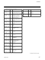
CONTENTS
Page
1. OUTLINE............................................................................... 1
1.1 Features ..........................................................................................................1
1.2 Handling Procedures .......................................................................................2
1.3 Checking the Products ....................................................................................3
1.4 Confirmation of the Model Code ......................................................................4
1.5 System Configuration ......................................................................................6
1.6 Parts Description ...........................................................................................12
2. SPECIFICATIONS .............................................................. 14
3. MOUNTING ......................................................................... 20
3.1 Mounting Cautions.........................................................................................20
3.2 Dimensions....................................................................................................21
3.3 Mounting the Mother Block ............................................................................22
3.4 Mounting the Module Mainframe ...................................................................24
3.5 Removing the Module Mainframe..................................................................24
4. WIRING .............................................................................. 25
4.1 Wiring ............................................................................................................25
4.2 Connections...................................................................................................27
4.2.1 DO connector connection................................................................................... 28
4.2.2 Connection to the host computer ....................................................................... 30
4.2.3 Connection to the operation panel ..................................................................... 37
4.2.4 Connection to the touch panel ........................................................................... 38
4.2.5 Multiple control unit connections ........................................................................ 41
5. SETTINGS BEFORE OPERATION .................................... 43
5.1 Protocol Selection and Host Communication Setting ....................................43
5.2 Unit Address Setting......................................................................................48
5.3 Start-up Procedures ......................................................................................49
5.4 Communication Requirements ......................................................................50
IMS01J02-E1
i-3
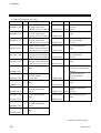
Page
6. RKC COMMUNICATION .................................................... 52
6.1 Protocol .........................................................................................................52
6.1.1 Polling ................................................................................................................ 52
6.1.2 Selecting ............................................................................................................ 57
6.1.3 Communication data structure ........................................................................... 60
6.1.4 Examples of polling and selecting check programs ........................................... 61
6.2 Communication Identifier List ........................................................................65
6.3 Initial Setting (Extended Communication)......................................................81
7. MODBUS .......................................................................... 109
7.1 Protocol .......................................................................................................109
7.1.1 Message format ............................................................................................... 109
7.1.2 Function code................................................................................................... 110
7.1.3 Communication mode ...................................................................................... 110
7.1.4 Slave responses............................................................................................... 111
7.1.5 Calculating CRC-16 ......................................................................................... 112
7.2 Message Format..........................................................................................115
7.2.1 Read holding registers [03H]............................................................................ 115
7.2.2 Preset single register [06H].............................................................................. 116
7.2.3 Diagnostics (Loopback test) [08H] ................................................................... 117
7.2.4 Preset multiple registers [10H] ......................................................................... 118
7.3 Communication Data ...................................................................................119
7.3.1 Data configuration ............................................................................................ 119
7.3.2 Data processing precautions............................................................................ 123
7.3.3 Communication data list................................................................................... 124
7.4 Data Map .....................................................................................................154
7.4.1 Reference to data map..................................................................................... 154
7.4.2 Data map list .................................................................................................... 155
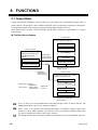
8. FUNCTIONS ..................................................................... 168
8.1 Output Ratio ................................................................................................168
8.2 Speed Control..............................................................................................172
8.2.1 Display scale .................................................................................................... 173
8.2.2 Measuring method ........................................................................................... 174
8.2.3 Output scale ..................................................................................................... 175
8.2.4 Output limiter.................................................................................................... 175
8.2.5 Controls............................................................................................................ 176
i-4
IMS01J02-E1
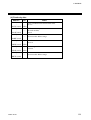
Page
8.2.6 Scale correction ............................................................................................... 179
8.2.7 Output change rate limiter................................................................................ 181
8.2.8 Alarm hold function .......................................................................................... 182
8.2.9 Assignment of channels ................................................................................... 183
9. TROUBLESHOOTING...................................................... 184
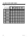
10. ASCII 7-BIT CODE TABLE ............................................ 190
IMS01J02-E1
i-5
MEMO
i-6
IMS01J02-E1
1. OUTLINE
This manual describes the specifications, mounting, wiring and communication of the H-PCP-J
module.
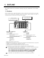
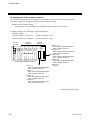
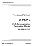
1.1 Features
H-PCP-J module (Power supply/CPU module) is made up of the CPU section and the power supply
section for the SR Mini HG SYSTEM control unit. H-PCP-J module includes two kinds of
communication port, and protocol of each port can be changed.
H-PCP-J module
(Power supply/CPU module)
Up to 10 function modules
can be connected.
SR Mini HG SYSTEM control unit
COM.PORT1/COM.PORT2
Interface: RS-422A
RS-485
Protocol: RKC communication protocol
Modbus protocol
The protocol corresponding to each PLC *
(Any can be selected with switch)
Connected equipment:
Host computer
Touch panel
Operation panel
PLC
COM.PORT3
Interface: RS-232C
RS-422A
RS-485
Protocol: RKC communication protocol
Modbus protocol
(Any can be selected with switch)
Connected equipment:
Host computer
Touch panel
Operation panel
* Usable programmable controller (PLC)
• MELSEC series (AnA/QnA, Q, A and FX series) manufactured by Mitsubishi Electric Corporation
• SYSMAC series manufactured by OMRON Corporation
• JW50H/70H/100H and JW30H manufactured by Sharp Corporation
• MASTER-K series and GLOFA-GM series manufactured by LG Industrial Systems
For programmable controller (PLC) communication, see usage PLC instruction manual and
following PLC Communication Instruction Manual.
• PLC Communication Instruction Manual [For MITSUBISHI PLC] (IMS01J03-E )
• PLC Communication Instruction Manual [For OMRON PLC] (IMS01J04-E )
• PLC Communication Instruction Manual [For SHARP PLC] (IMS01J05-E )
• PLC Communication Instruction Manual [For LG PLC] (IMS01J06-E )
COM.PORT1 and COM.PORT2 become the same communication specification.
IIMS01J02-E1
1
1. OUTLINE
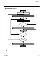
1.2 Handling Procedures
Conduct handling according to the procedure described below.
See 1.3 Checking the Products (P. 3)
See 1.4 Confirmation of the Model Code (P. 4)
Checking the products
See 3. MOUNTING (P. 20)
Mounting
See 4.1 WIRING (P. 25)
Power supply/ground
wiring
Connections
DO connector connection
See P. 28
Connection to the host computer
See P. 30
Connection to the operation panel
See P. 37
Connection to the touch panel
See P. 38
Multiple control unit connections
See P. 41
Connection to the PLC
MITSUBISHI MELSEC series
See PLC Communication Instruction Manual
[For MITSUBISHI PLC] (IMS01J03-E )
OMRON SYSMAC series
See PLC Communication Instruction Manual
[For OMRON PLC] (IMS01J04-E )
SHARP JW50H/70H/100H and JW30H
See PLC Communication Instruction Manual
[For SHARP PLC] (IMS01J05-E )
LG MASTER-K and GLOFA-GM series
See PLC Communication Instruction Manual
[For LG PLC] (IMS01J06-E )
Settings prior to
operation
RKC and MODBUS communication
Protocol Selection and Host Communication Setting
See P. 43
Unit Address Setting
See P. 48
PLC communication
MITSUBISHI MELSEC series
See PLC Communication Instruction Manual
[For MITSUBISHI PLC] (IMS01J03-E )
Current transformer (CT) monitor
OMRON SYSMAC series
See PLC Communication Instruction Manual
[For OMRON PLC] (IMS01J04-E )
Current transformer (CT) monitor
SHARP JW50H/70H/100H and JW30H
See PLC Communication Instruction Manual
[For SHARP PLC] (IMS01J05-E )
LG MASTER-K and GLOFA-GM series
See PLC Communication Instruction Manual
[For LG PLC] (IMS01J06-E )
Start-up procedures
See 5.3 Start-up Procedures (P. 49)
Operations
2
IIMS01J02-E1
1. OUTLINE
1.3 Checking the Products
When unpacking your new instrument, please confirm that the following products are included. If any
of the products are missing, damaged, or if your manual is incomplete, please contact RKC sales office
or agent for replacement.
Power supply/CPU module, H-PCP-J .... 1 module
One H-PCP-J module (power supply/CPU module) is required for each control unit.
Function modules .... Required number of modules
Reference purchase order for description of function modules.
DIN rail holding clips .... Two clips per unit
H-PCP-J Instruction Manual (IMS01J02-E ) ....1 copy
PLC Communication Instruction Manual (IMS01J0 -E ) ..... 1 copy
The specified PLC Communication Instruction Manual is attached.
• PLC Communication Instruction Manual [For MITSUBISHI PLC] (IMS01J03-E )
• PLC Communication Instruction Manual [For OMRON PLC] (IMS01J04-E )
• PLC Communication Instruction Manual [For SHARP PLC] (IMS01J05-E )
• PLC Communication Instruction Manual [For LG PLC] (IMS01J06-E )
Hardware Instruction Manual (IMSRM15-E ) ....1 copy
H-DO-G Instruction Manual (IMS01K01-E ) .... 1 copy
This manual is attached regardless of the presence or absence of the H-DO-G module.
H-SIO-A Instruction Manual (IMS01L01-E ) .... 1 copy
This manual is attached regardless of the presence or absence of the H-SIO-A module.
IIMS01J02-E1
3
1. OUTLINE
1.4 Confirmation of the Model Code
The model code for the instrument you received is listed below. Please confirm that you have received
the correct instrument by checking the model code label, located on the left side of the module, with
this list. If the product you received is not the one ordered, please contact RKC sales office or agent
for replacement.
-D∗
H-PCP- J (1)
(2) (3)
(4)
(5)
(1) Type
(6) (7)
(8)
(9)
(7) Alarm 2 function *
J: PLC communication type
(2) Power supply voltage
N: No alarm function
: See Alarm code table (P. 5)
(8) An attached instruction manual
1: 100 to 120 V AC
2: 200 to 240 V AC
3: 24 V DC
00: H-PCP-J Instruction Manual
(3) Communication interface
(COM. PORT1/COM. PORT2)
4: RS-422A
5: RS-485
(4) Communication interface
(COM. PORT3)
1: RS-232C
4: RS-422A
5: RS-485
02: H-PCP-J Instruction Manual and
PLC Communication Instruction Manual
[For MITSUBISHI PLC]
03: H-PCP-J Instruction Manual and
PLC Communication Instruction Manual
[For OMRON PLC]
04: H-PCP-J Instruction Manual and
PLC Communication Instruction Manual
[For SHARP PLC]
05: H-PCP-J Instruction Manual and
PLC Communication Instruction Manual
[For LG PLC]
(9) Instruction manual language
(5) DO signal
E: English
J: Japanese
D: Open collector output
(6) Alarm 1 function *
N: No alarm function
: See Alarm code table (P. 5)
* It is alarm function of H-TIO-
4
module, H-CIO-A module and H-SIO-A module.
IIMS01J02-E1
1. OUTLINE
Initial code
NNNN -
(1) (2)
(3) (4)
(1) TI alarm 1 function
(3) AI alarm 1 function
N: No alarm function
: See TI/AI alarm code table (P. 5)
N: No alarm function
: See TI/AI alarm code table (P. 5)
(2) TI alarm 2 function
(4) AI alarm 2 function
N: No alarm function
: See TI/AI alarm code table (P. 5)
N: No alarm function
: See TI/AI alarm code table (P. 5)
Alarm code table
A:
C:
E:
G:
J:
L:
Deviation high alarm
Deviation high and low alarm
Deviation high alarm with hold action
Deviation high and low alarm with hold action
Process low alarm
Process low alarm with hold action
B: Deviation low alarm
D: Band alarm
F: Deviation low alarm with hold action
H: Process high alarm
K: Process high alarm with hold action
Special alarm function
Q: Deviation high alarm with re-hold action
R: Deviation low alarm with re-hold action
T: Deviation high and low alarm with re-hold action
TI/AI alarm code table
H:
J:
K:
L:
Process high alarm
Process low alarm
Process high alarm with hold action
Process low alarm with hold action
The selected alarm function will be common for all the modules with alarm functions in the
control unit.
IIMS01J02-E1
5
1. OUTLINE
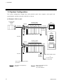
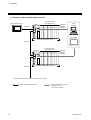
1.5 System Configuration
The system configuration example that used operation panel, host computer, touch panel and
programmable controller (hereafter called PLC) is shown.
Example 1: PLC is used
Programmable
controller
(PLC)
H-PCP-J
Function module
(10 modules max.)
RKC
operation panel
RS-422A
RS-422A
RS-422A
RS-485
RS-232C
or
Host
computer
SR Mini HG SYSTEM control unit
RS-422A
H-PCP-J
Function module
(10 modules max.)
Touch panel
RS-422A
SR Mini HG SYSTEM control unit
RS-422A
RS-422A
RS-485
RS-232C
To RKC operation panel
or
To host computer
To touch panel
Up to 4 units per communication
port of PLC
: The protocol corresponding to
each PLC
6
: RKC communication protocol
Modbus protocol
Any can be selected
IIMS01J02-E1
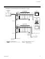
1. OUTLINE
Example 2: Current transformer (CT) monitor (PLC is used)
Programmable
controller
(PLC)
H-PCP-J
H-CT-A module
(10 modules max.)
RKC
operation panel
RS-422A
RS-422A
RS-422A
RS-485
RS-232C
or
Host
computer
SR Mini HG SYSTEM control unit
RS-422A
H-PCP-J
H-CT-A module
(10 modules max.)
Touch panel
RS-422A
SR Mini HG SYSTEM control unit
RS-422A
RS-422A
RS-485
RS-232C
To RKC operation panel
or
To host computer
To touch panel
Up to 16 units per communication
port of PLC
: PLC special protocol
[Current transformer (CT) monitor]
IIMS01J02-E1
: RKC communication protocol
Modbus protocol
Any can be selected
7
1. OUTLINE
Example 3: RKC operation panel is used
RKC operation panel
H-PCP-J
Function module
(10 modules max.)
RS-422A
RS-422A
RS-485
RS-232C
Host
computer
Touch panel
SR Mini HG SYSTEM control unit
RS-422A
H-PCP-J
RS-422A
Function module
(10 modules max.)
RS-422A
RS-485
RS-232C
SR Mini HG SYSTEM control unit
When the RKC operation panel is connected: Up to 8 units
: RKC communication protocol
8
: RKC communication protocol
Modbus protocol
Any can be selected
IIMS01J02-E1
1. OUTLINE
Example 4: Host computer or touch panel is used
H-PCP-J
Host
computer
Function module
(10 modules max.)
RS-422A
RS-485
RKC operation panel
RS-422A
Touch panel
SR Mini HG SYSTEM control unit
RS-422A
RS-485
H-PCP-J
Function module
(10 modules max.)
RS-422A
SR Mini HG SYSTEM control unit
RS-422A
RS-485
When the host computer is connected: Up to 16 units
When the is touch panel connected:
Up to 16 units
: RKC communication protocol
Modbus protocol
Any can be selected
IIMS01J02-E1
: RKC communication protocol
9
1. OUTLINE
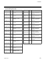
Usable modules
The following function modules can be used in combination with the H-PCP-J module. However,
usable module is different by protocol.
RKC communication protocol/Modbus protocol
Function module
Temperature control module
Position proportioning control module
Speed control module
Temperature input module
Cascade control module
Current transformer input module
Digital input module
Digital output module
Analog input module
Analog output module
Type
H-TIO-A
H-TIO-E
H-TIO-J
H-TIO-K
H-SIO-A
H-TI-A
H-CIO-A
H-CT-A
H-DI-A
H-DO-A
H-DO-G
H-AI-A
H-AO-A
H-TIO-B
H-TIO-F
H-TIO-P
H-TIO-C
H-TIO-G
H-TIO-R
H-TI-B
H-TI-C
H-DI-B
H-DO-B
H-DO-C
H-TIO-D
H-TIO-H
H-DO-D
H-AI-B
H-AO-B
PLC special protocol
Function module
Temperature control module
Position proportioning control module *
Speed control module *
Cascade control module *
Current transformer input module
Type
H-TIO-A
H-TIO-E
H-TIO-J
H-TIO-K
H-SIO-A
H-CIO-A
H-CT-A
H-TIO-B
H-TIO-F
H-TIO-P
H-TIO-C
H-TIO-G
H-TIO-R
H-TIO-D
H-TIO-H
* There is restriction on usable data in case of PLC communication protocol.
Current transformer (CT) monitor special protocol
Function module
Current transformer input module
Type
H-CT-A
For the function modules, see the Hardware Instruction Manual (IMSRM15-E ),
H-DO-G Instruction Manual (IMS01K01-E ) and H-SIO-A Instruction Manual
(IMS01L01-E ).
Maximum number of function modules that can be connected to one control unit:
10 modules/control unit
10
IIMS01J02-E1
1. OUTLINE
Precautions for PLC communication system configuration
When a system is configured by connecting a PLC, the protocol dedicated to the PLC (for temperature
control) cannot be used together with the current transformer (CT) monitor.
MITSUBISHI MELSEC series
PLC
MITSUBISHI MELSEC series
SR Mini HG SYSTEM control unit
H-PCP-J module
Set the MITSUBISHI MELSEC series special protocol
[Temperature control]
SR Mini HG SYSTEM control unit
H-PCP-J module
Set the MITSUBISHI MELSEC series special protocol
[Current transformer (CT) monitor]
OMRON SYSMAC series
PLC
OMRON SYSMAC series
SR Mini HG SYSTEM control unit
H-PCP-J module
Set the OMRON SYSMAC series special protocol
[Temperature control]
SR Mini HG SYSTEM control unit
H-PCP-J module
Set the OMRON SYSMAC series special protocol
[Current transformer (CT) monitor]
IIMS01J02-E1
11
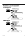
1. OUTLINE
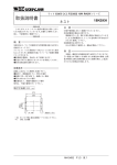
1.6 Parts Description
H-PCP-J module
(1)
(8)
(9)
(2)
(7)
(10)
(3)
(6)
(4)
(11)
(5)
Front
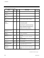
No.
Side
Name
Description
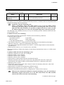
(1)
Unit address setting switch
Set unit address number of control unit
Setting range: 0 to 15 (0 to F, hexadecimal)
(2)
Status indication lamps
RX1 (data reception) lamp [Yellow]
ON during COM.PORT1/COM.PORT2 data is
correctly received
RX2 (data reception) lamp [Yellow]
ON during COM.PORT3 data is correctly
received
EVENT lamp [Green]
ON during event operation
(Always OFF because there is not event function)
FAIL lamp [Red]
ON during abnormal operation
OFF during normal operation
TX1 (data transmission) lamp [Yellow]
ON during COM.PORT1/COM.PORT2 data is
correctly sent
TX2 (data transmission) lamp [Yellow]
ON during COM.PORT3 data is correctly sent
START lamp [Green]
ON during control
RUN lamp [Green]
Flashing during normal operation
ON during abnormal operation
RX1
RX2 EVENT FAIL
TX1
TX2
START RUN
Continued on the next page.
12
IIMS01J02-E1
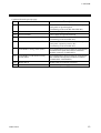
1. OUTLINE
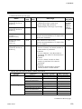
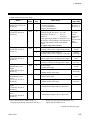
Continued from the previous page.
No.
Name
Description
(3)
Modular connector (COM.PORT3)
Connector for connection with the host computer,
touch panel or operation panel
(Conforming to RS-232C/RS-422A/RS-485)
(4)
DO connector
Connector for digital output
(5)
Power terminals
Power supply and ground terminals
(6)
Modular connector (COM.PORT2)
Connector for the control unit addition
(Conforming to RS-422A/RS-485)
(7)
Modular connector (COM.PORT1)
Connector for connection with the host computer,
touch panel, operation panel or PLC
(Conforming to RS-422A/RS-485)
(8)
COM.PORT3 setting switch (SW3)
Set communication protocol, data bit configuration,
communication speed and initialize method of
modular connector (COM.PORT3).
(9)
COM.PORT1/COM.PORT2 setting
switch (SW2)
Set communication protocol, data bit configuration
and communication speed of modular connector
(COM.PORT1/COM.PORT2).
(10)
Mother block
Module DIN rail mounting connector
(11)
Module connector
Connector for power supply and bus connection
IIMS01J02-E1
13
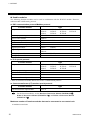
2. SPECIFICATIONS
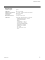
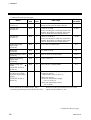
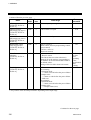
Basic functions
Data supervision:
Operating and system data
Control unit diagnosis:
Function modules configuration check
Self-diagnostic:
Check item: ROM/RAM check
Watchdog timer
Power supply monitoring
If error occurs in self-diagnosis, the hardware will automatically
return the module outputs to the OFF position.
Memory backup:
Lithium battery for RAM backup, approximate 10 years life for data
retention.
Power input
Power supply voltage:
100 to 120 V AC (50/60 Hz) , 200 to 240 V AC (50/60 Hz) or
24 V DC
Specify when ordering
Power supply voltage range: 100 to 120 V AC: 90 to 132 V AC
200 to 240 V AC: 180 to 264 V AC
24 V DC:
21.6 to 26.4 V DC
Power consumption:
100 to 120 V AC: 40 VA max.
200 to 240 V AC: 50 VA max.
24 V DC:
21 W max. 1 A or less
Surge current:
30 A or less
Power output (Function module power)
14
Output voltage/current:
5 V DC, 1.7 A max.
12V DC, 1.0 A max.
Overcurrent protection:
Fold-back limiting method: 5 V
IIMS01J02-E1
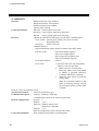
2. SPECIFICATIONS
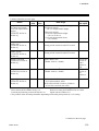
Digital output
Number of outputs:
8 points
Output type:
Open collector output
Number of common points:
Vcc: 2 points, GND: 2 points (8 points/common)
Isolation method:
Photocoupler isolation
Load voltage:
12 to 24 V DC
Maximum load current:
0.1 A/point, 0.8 A/common
Output data:
Digital output can be selected from the following:
− Temperature alarm (Alarm 1, Alarm 2)
− Heater break alarm (HBA)
− Burnout
− TI Alarm (Alarm 1, Alarm 2)
− AI Alarm (Alarm 1, Alarm 2)
− Control loop break alarm (LBA)
− Temperature rise completion
− Temperature rise completion
− FAIL output
− PLC communication status
− Unused
IIMS01J02-E1
15
2. SPECIFICATIONS
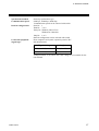
Communication functions
COM.PORT1/COM.PORT2
Interface:
Based on RS-422A, EIA standard
Based on RS-485, EIA standard
Specify when ordering
Connection method:
RS-422A: 4-wire system, multi-drop connection
RS-485: 2-wire system, multi-drop connection
Protocol:
• Based on ANSI X3.28 subcategory 2.5 B1 (RKC communication)
Error control: Vertical parity (when parity bit is selected)
Horizontal parity
Data types:
ASCII 7-bit code
• Modbus protocol
Signal transmission mode: Remote Terminal Unit (RTU) mode
Function codes:
03H Read holding registers
06H Preset single register
08H Diagnostics (loopback test)
10H Preset multiple registers
Error check method:
CRC-16
Error codes:
1: Function code error (An unsupported
function code was specified)
2: − When written to read only data
− When any address other than 0000H
to 02EEH is specified (However,
07D0H to 0BB7H are excluded)
3: − When the data written exceeds the
setting range
− When the specified number of data
items in the query message exceeds
the maximum number of data items
available
• MITSUBISHI MELSEC series special protocol
AnA/AnUCPU common command (QW/QR)
• MITSUBISHI MELSEC series special protocol
ACPU common command (WW/WR)
• OMRON SYSMAC series special protocol
• SHARP JW50H/70H/100H and JW30H special protocol
Computer link (command mode)
• LG MASTER-K and GLOFA-GM series special protocol
Protocol can be selected with switch
16
IIMS01J02-E1
2. SPECIFICATIONS
Synchronous method:
Communication speed:
Connected equipment:
Start/stop synchronous type
9600 bps, 19200 bps, 38400 bps
Communication speed can be selected with switch
Start bit: 1
Data bit: 7 or 8
Parity bit: Without, Odd or Even
Without for 8 data bits
Stop bit: 1 or 2
Data bit configuration can be selected with switch
Host computer, touch panel, operation panel or PLC
Signal logic:
RS-422A/RS-485
Data bit configuration:
Signal voltage
Logic
V (A) − V (B) ≥ 2 V
0 (SPACE)
V (A) − V (B) ≤ −2 V
1 (MARK)
Voltage between V (A) and V (B) is the voltage of (A) terminal for the
(B) terminal.
IIMS01J02-E1
17
2. SPECIFICATIONS
COM.PORT3
Interface:
Connection method:
Protocol:
Based on RS-232C, EIA standard
Based on RS-422A, EIA standard
Based on RS-485, EIA standard
Specify when ordering
RS-232C: Point-to-point connection
RS-422A: 4-wire system, multi-drop connection
RS-485: 2-wire system, multi-drop connection
• Based on ANSI X3.28 subcategory 2.5 B1 (RKC communication)
Error control: Vertical parity (when parity bit is selected)
Horizontal parity
Data types:
ASCII 7-bit code
• Modbus protocol
Signal transmission mode: Remote Terminal Unit (RTU) mode
Function codes:
03H Read holding registers
06H Preset single register
08H Diagnostics (loopback test)
10H Preset multiple registers
Error check method:
CRC-16
Error codes:
1: Function code error (An unsupported
function code was specified)
2: − When written to read only data
− When any address other than 0000H
to 02EEH is specified (However,
07D0H to 0BB7H are excluded)
3: − When the data written exceeds the
setting range
− When the specified number of data
items in the query message exceeds
the maximum number of data items
available
Protocol can be selected with switch
Synchronous method:
Start/stop synchronous type
Communication speed:
9600 bps, 19200 bps, 38400 bps
Communication speed can be selected with switch
Data bit configuration:
Start bit: 1
Data bit: 7 or 8
Parity bit: Without, Odd or Even
Without for 8 data bits
Stop bit: 1 or 2
Data bit configuration can be selected with switch
Connected equipment:
Host computer, touch panel or operation panel
18
IIMS01J02-E1
2. SPECIFICATIONS
Signal logic:
RS-232C
Signal voltage
Logic
+3 V or more
0 (SPACE)
−3 V or less
1 (MARK)
RS-422A/RS-485
Signal voltage
Logic
V (A) − V (B) ≥ 2 V
0 (SPACE)
V (A) −V (B) ≤ −2 V
1 (MARK)
Voltage between V (A) and V (B) is the voltage of (A) terminal for the
(B) terminal.
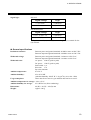
General specifications
Insulation resistance:
Between power and ground terminals: 20 MΩ or more at 500 V DC
Between output and ground terminals: 20 MΩ or more at 500 V DC
Withstand voltage:
Between power and ground terminals: 1 minute at 1500 V AC
Between output and ground terminals: 1 minute at 1500 V AC
Withstand noise:
AC power: 2500 V (peak to peak)
DC power: 1500 V (peak to peak)
Pulse width: 1 µs
Rise time: 1 ns
By noise simulator
Ambient temperature:
0 to 50 °C
Ambient humidity:
45 to 85 % RH
(Absolute humidity: MAX. W. C 29 g/m3 dry air at 101.3 kPa)
Usage atmosphere:
There must be no corrosive gas and dust must not be excessive.
Ambient temperature for storage: −20 to +50 °C
Ambient humidity for storage:
95 % RH or less (Non condensing)
Dimensions:
48 (W) × 96 (H) × 100 (D) mm
Weight:
Approx. 300 g
IIMS01J02-E1
19
3. MOUNTING
This chapter describes the mounting procedures for the H-PCP-J modules. For details of the mounting
procedures for other modules and the mounting position of the control unit, see the Hardware
Instruction Manual (IMSRM15-E ).
!
WARNING
To prevent electric shock or instrument failure, always turn off the power before
mounting or removing the modules.
3.1 Mounting Cautions
(1) This instrument is intended to be used under the following environmental conditions. (IEC61010-1)
[OVERVOLTAGE CATEGORY II, POLLUTION DEGREE 2]
(2) Use this instrument within the following ambient temperature and ambient humidity.
• Ambient temperature: 0 to 50 °C
• Ambient humidity:
45 to 85 % RH
(Absolute humidity: MAX. W. C 29 g/m3 dry air at 101.3 kPa)
(3) Avoid the following conditions when selecting the mounting location:
• Rapid changes in ambient temperature which may cause condensation.
• Corrosive or inflammable gases.
• Direct vibration or shock to the mainframe.
• Water, oil, chemicals, vapor or steam splashes.
• Excessive dust, salt or iron particles.
• Excessive induction noise, static electricity, magnetic fields or noise.
• Direct air flow from an air conditioner.
• Exposure to direct sunlight.
• Excessive heat accumulation.
20
IIMS01J02-E1
3. MOUNTING
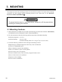
3.2 Dimensions
External dimensions
48
4
(Unit: mm)
96
100
3.5
110
Module mounting depth
The mounting depth of each module is 108 mm from the mounting surface inside the panel to the front
of the module with the module mounted on the DIN rail. However, when modular connector cables are
plugged in, additional depth is required.
(Unit: mm)
Approx.
50
108
DIN rail
IMS01J02-E1
21
3. MOUNTING
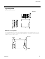
3.3 Mounting the Mother Block
The mother block can be mounted to a panel or DIN rail.
Mount the H-PCP-J module on the left side of the control unit.
Panel mounting directions
1. Refer to both the panel mounting dimensions below and the external dimensions in previous
section when selecting the location.
(Unit: mm)
4-M3
24
24
24
77
77
24
H-PCP-J module
Dimensions for multiple
module mounting
2. Remove the module from the mother block. For details of removing the module,
see 3.5 Removing the Module Mainframe (P. 24).
3. Connect the mother blocks together before tightening the screws on the panel.
(Customer must provide the set screws)
M3 × 10
Recommended tightening torque:
0.3 N⋅m (3 kgf⋅cm)
When the mother block is mounted on the
panel, 50 mm or more space is required at the
top and bottom of the mother block to attach
the module mainframe.
Mother block
22
IMS01J02-E1
3. MOUNTING
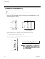
DIN rail mounting directions
1. Remove the module mainframe from the mother block. For details of removing the module
mainframe, see 3.5 Removing the Module Mainframe (P. 24).
2. Pull down both locking devices at the bottom of the mother block. (Figure 1)
3. Attach the top bracket of the mother block to the DIN rail and push the lower section into place
on the DIN rail. (Figure 2)
4. Slide the locking devices up to secure the mother block to the DIN rail. (Figure 3)
5. Slide connectors together to complete mother block installation. (Figure 4)
Locking device
Figure 1
Figure 2
Figure 3
Figure 4
When the mother block is mounted on panel, 50 mm or more space is required at the
top and bottom of the mother block to attach the module mainframe.
IMS01J02-E1
23
3. MOUNTING
3.4 Mounting the Module Mainframe
1. Place the module mainframe opening on top of the mother block tab. (Figure 1)
2. Snap the lower part of module mainframe on to the mother block. (Figure 2)
A snapping sound will be heard when module mainframe is securely connected to mother block.
Opening at top of module
Tab at top of mother block
Figure 1
Figure 2
3.5 Removing the Module Mainframe
To separate the module mainframe from the mother block, press the bottom on the module, lifting
upward, to release connection.
Mother block
Module mainframe
Module mainframe
Upper
section
Lower
section
Mother block
Press bottom of module and
lift upward to release
24
IMS01J02-E1
4. WIRING
4.1 Wiring
!
WARNING
To prevent electric shock or instrument failure, do not turn on the power until all
the wiring is completed.
CAUTION
Power supply wiring:
Use power supply as specified in power supply voltage range.
Power supply wiring must be twisted and have a low voltage drop.
Provide separate power supply for this instrument independent of other input/output
circuits, motors, equipment and operating circuits.
If there is electrical noise in the vicinity of the instrument that could affect operation, use
a noise filter.
− Shorten the distance between the twisted power supply wire pitches to achieve the
most effective noise reduction.
− Always install the noise filter on a grounded panel.
− Minimize the wiring distance between the noise filter output and the instrument power
supply terminals to achieve the most effective noise reduction.
− Do not connect fuses or switches to the noise filter output wiring as this will reduce the
effectiveness of the noise filter.
− Take into consideration the instrument power supply voltage and filter frequency
characteristics when selecting the most effective noise filter.
To the instrument with power supply of 24 V, please be sure to supply the power from
SELV circuit.
Ground wiring:
Ground the instrument separately from other equipment. The grounding resistance
should be 100 Ω or less.
Use grounding wires with a cross section area of 2.0 mm2 or more.
IMS01J02-E1
25
4. WIRING
Terminal configuration
Power terminals
DC +
12
24 V
−
AC L
12
N
12
100-120 V
200-240 V
13
AC L
13
N
13
Ground terminal
12
13
14
14
Terminal Screws
Screw size: M3
Recommended tightening torque: 0.4 N⋅m (4 kgf⋅cm)
Power supply
90 to 132 V AC
Including power supply voltage variations
(Rating: 100 to 120 V AC, Single phase 50/60 Hz)
180 to 264 V AC Including power supply voltage variations
(Rating: 200 to 240 V AC, Single phase 50/60 Hz)
21.6 to 26.4 V DC Including power supply voltage variations
(Rating: 24 V DC)
Specify when ordering
Ground
Ground the module using grounding wire with a cross section area of 2 mm2 or more and with a
grounding resistance of 100 Ω or less. Do not connect the grounding wire to the grounding wire of
any other equipment.
26
IMS01J02-E1
4. WIRING
4.2 Connections
!
WARNING
To prevent electric shock or instrument failure, turn off the power before
connecting or disconnecting the instrument and peripheral equipment.
CAUTION
Connect connectors correctly in the right position. If it is forcibly pushed in with pins in
the wrong positions, the pins may be bent resulting in instrument failure.
When connecting or disconnecting the connectors, do not force it too far to right and left
or up and down, but move it on the straight. Otherwise, the connector pins may be bent,
causing instrument failure.
When disconnecting a connector, hold it by the connector itself. Disconnecting
connectors by yanking on their cables can cause breakdowns.
To prevent malfunction, never touch the contact section of a connector with bare hands
or with hands soiled with oil or the like.
To prevent malfunction, connect cable connectors securely, then firmly tighten the
connector fastening screws.
To prevent damage to cables, do not bend cables over with excessive force.
If the instrument is easily affected by noise, use the ferrite core in the both ends of the
communication cable (nearest the connector).
IMS01J02-E1
27
4. WIRING
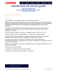
4.2.1 DO connector connection
DO connector
20
10
11
1
Output type: Open collector output
Number of common points:
Vcc: 2 points,
GND: 2 points (8 points/common)
Isolation method:
Photocoupler isolation
Load voltage: 12 to 24 V DC
Maximum load current:
0.1 A/point, 0.8 A/common
Connector used:
MIL connector AXM220011
(Manufactured by Matsushita
Electric Works, Ltd.)
Connector pin number and signal details
Pin No.
20
19
18
17
16
15
14
13
12
11
Description
Pin No.
10
9
8
7
6
5
4
3
2
1
VCC (COM) +
GND (COM) −
Unused
Unused
Unused
Unused
Unused
Unused
Unused
Unused
Description
VCC (COM) +
GND (COM) −
DO8
DO7
DO6
DO5
DO4
DO3
DO2
DO1
Recommended terminals
• When using the relay contact outputs
PC relay terminal: Model No.: RT1S-OD08-24V-S [Part No.: AY112402]
Model No.: RT1S-OD08-12V-S [Part No.: AY112401]
(Manufactured by Matsushita Electric Works, Ltd.)
• When using the PC terminal that interface relay or SSR (sold separately) is installed
PC terminal:
Model No.: RT1-OD08-24V-S [Part No.: AY102402]
Model No.: RT1-OD08-12V-S [Part No.: AY102401]
(Manufactured by Matsushita Electric Works, Ltd.)
• When using the terminal for open collector outputs
Connector terminal: Model No.: CT1-20 [Part No.: AYT1120]
(Manufactured by Matsushita Electric Works, Ltd.)
Recommended cable and connector
• PC relay terminals/PC terminals expansion cable
Part No.: AY1584 * (Manufactured by Matsushita Electric Works, Ltd.)
*
→ 0: 70 mm
1: 250 mm
2: 500 mm
3: 1000 mm
5: 2000 mm
• MIL connector
Part No.: AXM120415 (Manufactured by Matsushita Electric Works, Ltd.)
For the DO allocation, see the H-PCP-J module DO type selection (P. 100, 141).
28
IMS01J02-E1
4. WIRING
Open collector output wiring example
COM (+)
20
10
Load
1
DO1
⋅
⋅
⋅
⋅
⋅
⋅
⋅
⋅
⋅
12 to 24 V DC
+
−
Load
In using the open collector output,
an external power supply of 24 V
DC is required.
Note that if this power supply is not
connected, there will be no output
from the module.
8
DO8
COM (−)
9
19
PC relay terminal connecting example
H-PCP-J module
Expansion cable
AY1584
PC relay terminal
RT1S-OD08-24V-S
(Manufactured by Matsushita
Electric Works, Ltd.)
(Manufactured by
Matsushita Electric
Works, Ltd.)
+
0+
+
0+
1+
2+
3+
4+
5+
6+
7+
: Unused
−
−
Terminal configuration of PC terminal
is the same as PC relay terminal.
1−
0−
1+
0−
1−
NO
24 V DC
2−
2+
2−
NO
DO1
3−
3+
4−
4+
3−
NO
5−
5+
4−
NO
6−
6+
5−
NO
6−
NO
DO2 DO3 DO4 DO5
7−
7+
7−
NO
NO
DO6 DO7 DO8
Connector terminal connecting example
H-PCP-J module
Expansion cable
AY1584
Connector terminal
CT1-20
(Manufactured by Matsushita
Electric Works, Ltd.)
(Manufactured by
Matsushita Electric
Works, Ltd.)
B1
B2
B3
B4
B5
B6
B7
B8
B9
B10
: Unused
A1
B1
A1
A2
A3
B2
A2
B3
B4
B5
B6
B7
B8
B9
B10
L
L
L
L
L
L
L
L
+ −
A4
A5
A6
A7
A8
A9
A10
12 to 24 V DC
DO8 DO7 DO6 DO5 DO4 DO3 DO2 DO1
IMS01J02-E1
29
4. WIRING
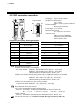
4.2.2 Connection to the host computer
Connection block diagram
The communication interface for control unit are RS-232C *, RS-422A and RS-485. When using the
RS-422A or RS-485, a maximum of 16 control units can be connected. However, when connecting to
the computer which only has a RS-232C driver, RS-232C/RS-422A converter or RS-232C/RS-485
converter will be necessary.
* RS-232C can be selected only COM. PORT3.
Host computer
Host computer
RS-232C
RS-232C
RS-422A
RS-485
RS-232C/RS-422A converter
or
RS-232C/RS-485A converter
Control unit
RS-422A
RS-485
Control unit
RS-422A
RS-485
When RS-232C is selected for the
control unit communications, only one
control unit may be connected.
Up to 16 units
30
IMS01J02-E1
4. WIRING
RS-232C
Host computer
Control unit
W-BF-28
Connect to the communication
connector
D-SUB 9-pin connector *
* Use D-SUB 25-pin modular conversion
connector (Recommended type:
TM12RV-64-H manufactured by
HIROSE ELECTRIC CO., LTD.)
when connector of host computer is
D-SUB 25-pin.
Connect to the [COM.PORT3]
on H-PCP-J module
Cable type: W-BF-28-3000 (RKC product, Sold separately)
[Standard cable length: 3 m]
Pin layout of modular connector (RS-232C)
H-PCP-J module
COM.PORT3
SG
6
Unused 5
RD
SG
SD
4
3
2
Unused 1
Connector pin number and signal details (RS-232C)
Pin No.
Signal name
Symbol
1
Unused
-
2
Send data
SD (TXD)
3
Signal ground
SG
4
Receive data
RD (RXD)
5
Unused
-
6
Signal ground
SG
IMS01J02-E1
31
4. WIRING
Diagram of RS-232C wiring
H-PCP-J
Host computer
SD (TXD) 2
SD (TXD)
RD (RXD) 4
RD (RXD)
SG
SG 3
* RS (RTS)
SG 6
Shielded wire
CS (CTS)
*Short RS and CS within
connector
Customer is requested to prepare a communication cable fit for the control unit to be
connected by the host computer. Connection cable W-BF-02 * and W-BF-28 * (RKC
product) can use to connect host computer.
* Shields of the cable are connected to SG (No. 6 pin) of the H-PCP-J connector.
The 6-pin type modular connector should be used for the connection to the H-PCP-J module.
Recommended model: TM4P-66P (Manufactured by HIROSE ELECTRIC CO., LTD.)
32
IMS01J02-E1
4. WIRING
RS-422A
RS-232C/RS-422A converter
COM-A (RKC product)
Control unit
RS-422A
Connect to the
[COM.PORT2]
Connect to the
[COM.PORT1]
W-BF-02
RS-232C
Connect to the
[COM.PORT1] or [COM.PORT3]
on H-PCP-J module
Host computer
D-SUB 9-pin connector *
W-BF-28
* Use D-SUB 25-pin modular conversion
connector (Recommended type:
TM12RV-64-H manufactured by
HIROSE ELECTRIC CO., LTD.)
when connector of host computer is
D-SUB 25-pin.
Connect to the communication
connector
Cable type:
W-BF-02-3000 (RKC product, Sold separately)
[Standard cable length: 3 m]
W-BF-28-3000 (RKC product, Sold separately)
[Standard cable length: 3 m]
Recommended RS-232C/RS-422A converter: COM-A (RKC product)
For the COM-A, see the COM-A/COM-B Instruction Manual (IMSRM33-E ).
IMS01J02-E1
33
4. WIRING
Pin layout of modular connector (RS-422A)
COM.PORT1
1
2
3
4
5
6
H-PCP-J module
COM.PORT3
R (A)
R (B)
SG
T (B)
T (A)
SG
SG
T (A)
T (B)
SG
R (B)
R (A)
6
5
4
3
2
1
Connector pin number and signal details (RS-422A)
Pin No.
Signal name
Symbol
1
Receive data
R (A)
2
Receive data
R (B)
3
Signal ground
SG
4
Send data
T (B)
5
Send data
T (A)
6
Signal ground
SG
Diagram of RS-422A wiring
Pair wire
H-PCP-J
Host computer
T (A)
5
T (A)
T (B)
4
T (B)
SG
3
SG
R (A)
1
R (A)
R (B)
2
R (B)
SG
6
Shielded twisted pair wire
Customer is requested to prepare a communication cable fit for the control unit to be
connected by the host computer. Connection cable W-BF-02 * and W-BF-28 * (RKC
product) can use to connect host computer.
* Shields of the cable are connected to SG (No. 6 pin) of the H-PCP-J connector.
The 6-pin type modular connector should be used for the connection to the H-PCP-J module.
Recommended model: TM4P-66P (Manufactured by HIROSE ELECTRIC CO., LTD.)
34
IMS01J02-E1
4. WIRING
RS-485
RS-232C/RS-485 converter
Unused
Control unit
R(B)
R(A)
T/R(B)
T(B)
T/R(A)
T(A)
SG
Orange
White
RS-485
W-BF-01
Black
Blue
Red
SG
RS-232C
Connect to the
[COM.PORT1] or [COM.PORT3]
on H-PCP-J module
Connect to the communication
connector
Host computer
Cable type: W-BF-01-3000 (RKC product, Sold separately) [Standard cable length: 3 m]
When the host computer (master) uses Windows 95/98/NT, use a RS-232C/RS-485
converter with an automatic send/receive transfer function.
Recommended: CD485, CD485/V manufactured by Data Link, Inc. or equivalent.
IMS01J02-E1
35
4. WIRING
Pin layout of modular connector (RS-485)
COM.PORT1
1
2
3
4
5
6
H-PCP-J module
COM.PORT3
T/R (A)
T/R (B)
SG
SG
6
Unused 5
Unused 4
Unused
Unused
SG
3
T/R (B) 2
T/R (A) 1
SG
Connector pin number and signal details (RS-485)
Pin No.
Signal name
Symbol
1
Send/receive data
T/R (A)
2
Send/receive data
T/R (B)
3
Signal ground
SG
4
Unused
-
5
Unused
-
6
Signal ground
SG
Diagram of RS-485 wiring
Pair wire
Host computer
H-PCP-J
T/R(A)
1
T/R (A)
T/R(B)
2
T/R (B)
SG
3
SG
SG
6
Shielded twisted pair wire
Customer is requested to prepare a communication cable fit for the control unit to be
connected by the host computer. Connection cable W-BF-01 * (RKC product) can use to
connect host computer.
* Shields of the cable are connected to SG (No. 6 pin) of the H-PCP-J connector.
The 6-pin type modular connector should be used for the connection to the H-PCP-J module.
Recommended model: TM4P-66P (Manufactured by HIROSE ELECTRIC CO., LTD.)
36
IMS01J02-E1
4. WIRING
4.2.3 Connection to the operation panel
For the connection cable, use the RKC product (Sold separately).
Cable type: W-BF-02-3000 [Standard cable length: 3 m]
Control unit
RS-422A
Connect to the modular
connector on operation panel
W-BF-02
[COM.PORT]
OPM-HL4
[CN3]
OPC-H
Connect to the
[COM.PORT1] or [COM.PORT3]
on H-PCP-J module
Pin layout of modular connector (RS-422A)
COM.PORT1
1
2
3
4
5
6
H-PCP-J module
R (A)
R (B)
SG
T (B)
T (A)
SG
COM.PORT3
SG
T (A)
T (B)
SG
R (B)
R (A)
6
5
4
3
2
1
Connector pin number and signal details (RS-422A)
Pin No.
Signal name
Symbol
1
Receive data
R (A)
2
Receive data
R (B)
3
Signal ground
SG
4
Send data
T (B)
5
Send data
T (A)
6
Signal ground
SG
IMS01J02-E1
37
4. WIRING
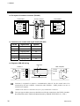
4.2.4 Connection to the touch panel
RS-232C
Pin layout of modular connector (RS-232C)
H-PCP-J module
COM.PORT3
SG
6
Unused 5
RD
SG
SD
4
3
2
Unused 1
Connector pin number and signal details (RS-232C)
Pin No.
Signal name
Symbol
1
Unused
-
2
Send data
SD (TXD)
3
Signal ground
SG
4
Receive data
RD (RXD)
5
Unused
-
6
Signal ground
SG
Diagram of RS-232C wiring
H-PCP-J
Touch panel
SD (TXD) 2
SD (TXD)
RD (RXD) 4
RD (RXD)
SG
SG 3
* RS (RTS)
SG 6
Shielded wire
CS (CTS)
*Short RS and CS within
connector
Customer is requested to prepare a communication cable fit for the control unit to be
connected by the touch panel.
The 6-pin type modular connector should be used for the connection to the H-PCP-J module.
Recommended model: TM4P-66P (Manufactured by HIROSE ELECTRIC CO., LTD.)
38
IMS01J02-E1
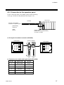
4. WIRING
RS-422A
Pin layout of modular connector (RS-422A)
COM.PORT1
1
2
3
4
5
6
H-PCP-J module
COM.PORT3
R (A)
R (B)
SG
T (B)
T (A)
SG
SG
T (A)
T (B)
SG
R (B)
R (A)
6
5
4
3
2
1
Connector pin number and signal details (RS-422A)
Pin No.
Signal name
Symbol
1
Receive data
R (A)
2
Receive data
R (B)
3
Signal ground
SG
4
Send data
T (B)
5
Send data
T (A)
6
Signal ground
SG
Diagram of RS-422A wiring
Pair wire
H-PCP-J
Touch panel
T (A)
5
T (A)
T (B)
4
T (B)
SG
3
SG
R (A)
1
R (A)
R (B)
2
R (B)
SG
6
Shielded twisted pair wire
Customer is requested to prepare a communication cable fit for the control unit to be
connected by the touch panel.
The 6-pin type modular connector should be used for the connection to the H-PCP-J module.
Recommended model: TM4P-66P (Manufactured by HIROSE ELECTRIC CO., LTD.)
IMS01J02-E1
39
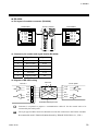
4. WIRING
RS-485
Pin layout of modular connector (RS-485)
COM.PORT1
1
2
3
4
5
6
H-PCP-J module
COM.PORT3
T/R (A)
T/R (B)
SG
SG
6
Unused 5
Unused 4
Unused
Unused
SG
3
T/R (B) 2
T/R (A) 1
SG
Connector pin number and signal details (RS-485)
Pin No.
Signal name
Symbol
1
Send/receive data
T/R (A)
2
Send/receive data
T/R (B)
3
Signal ground
SG
4
Unused
-
5
Unused
-
6
Signal ground
SG
Diagram of RS-485 wiring
Pair wire
Touch panel
H-PCP-J
T/R(A)
1
T/R (A)
T/R(B)
2
T/R (B)
SG
3
SG
SG
6
Shielded twisted pair wire
Customer is requested to prepare a communication cable fit for the control unit to be
connected by the touch panel.
The 6-pin type modular connector should be used for the connection to the H-PCP-J module.
Recommended model: TM4P-66P (Manufactured by HIROSE ELECTRIC CO., LTD.)
40
IMS01J02-E1
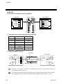
4. WIRING
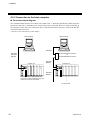
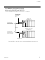
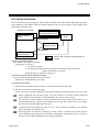
4.2.5 Multiple control unit connections
When using COM.PORT1 and COM.PORT2:
Connect COM.PORT2 on unit address 1 to COM.PORT1 on unit address 2.
Operation panel
Host computer
Touch panel
PLC
Control unit
(Unit address 1)
Connect to the
[COM.PORT2] on
H-PCP-J module
W-BF-02
Extension control unit
(Unit address 2)
Connect to the
[COM.PORT1] on
H-PCP-J module
Unit address 3
Cable type: W-BF-02-3000 (RKC product, Sold separately) [Standard cable length: 3 m]
IMS01J02-E1
41
4. WIRING
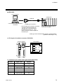
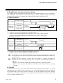
When using COM.PORT3:
Operation panel
Host computer
Touch panel
RS-422A
RS-485
Junction terminals
W-BF-01
RS-422A
W-BF-01 RS-485
Control unit
(Unit address 1)
Connect to the
terminals
W-BF-01
Connect to the [COM.PORT3]
on H-PCP-J module
Connect to the
terminals
Extension control unit
(Unit address 2)
Junction terminals or
Control unit (Unit address 3)
RS-422A
RS-485
Cable type: W-BF-01-3000 (RKC product, Sold separately)
[Standard cable length: 3 m]
Connect to the [COM.PORT3]
on H-PCP-J module
[RS-422A]
[RS-485]
R(B)
R(B)
R(A)
R(A)
T/R (B)
T(B)
T(B)
T/R (A)
T(A)
T(A)
SG
SG
SG
Orange
White
W-BF-01
Black
Blue
Red
Connect according to the label names as they
are without crossing the wires.
In case of RS-485 interface, be sure to insulate
the terminals that are not used by covering them
with insulating tape.
42
IMS01J02-E1
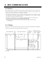
5. SETTINGS BEFORE OPERATION
5.1 Protocol Selection and Host Communication Setting
!
WARNING
To prevent electric shock or instrument failure, always turn off the power
before setting the switch.
To prevent electric shock or instrument failure, never touch any section other
than those instructed in this manual.
Protocol, data bit configuration, communication speed and initialize method can be set with the dip
switches located in the H-PCP-J module.
COM.PORT1/COM.PORT2
setting switch (SW2)
ON
12345678
COM.PORT3 setting switch
(SW3)
ON
12345678
Right side view
IMS01J02-E1
43
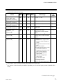
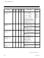
5. SETTINGS BEFORE OPERATION
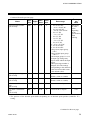
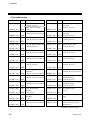
COM.PORT1/COM.PORT2 setting switch (SW2)
SW2
1
OFF
ON
OFF
ON
2
OFF
OFF
ON
ON
Data bit configuration
Data 8-bit, Without parity, Stop 1-bit
Data 7-bit, Odd parity, Stop 1-bit
Data 7-bit, Even parity, Stop 1-bit
Data 7-bit, Even parity, Stop 2-bit
Factory set value: Data 8-bit, Without parity, Stop 1-bit
SW2
3
OFF
ON
OFF
ON
4
OFF
OFF
ON
ON
Communication speed
9600 bps
19200 bps
38400 bps
Do not set this one
Factory set value: 9600 bps
Continued on the next page.
44
IMS01J02-E1
5. SETTINGS BEFORE OPERATION
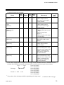
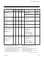
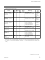
COM.PORT1/COM.PORT2 setting switch (SW2)
SW2
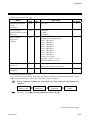
5
6
7
8
OFF
OFF
OFF
OFF
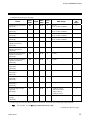
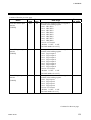
Protocol
RKC communication protocol
(Based on ANSI X3.28 subcategory 2.5 B1)
See 6. RKC COMMUNICATION (P. 52).
ON
OFF
OFF
OFF
Modbus protocol
See 7. MODBUS (P. 109).
OFF
ON
OFF
OFF
MITSUBISHI MELSEC series special protocol
AnA/AnUCPU common command (QW/QR)
See PLC Communication Instruction Manual
[For MITSUBISHI PLC] (IMS01J03-E ).
ON
ON
OFF
OFF
MITSUBISHI MELSEC series special protocol
ACPU common command (WW/WR)
See PLC Communication Instruction Manual
[For MITSUBISHI PLC] (IMS01J03-E ).
OFF
OFF
ON
OFF
MITSUBISHI MELSEC series special protocol
AnA/AnUCPU common command (QW/QR)
[Current transformer (CT) monitor] *
See PLC Communication Instruction Manual
[For MITSUBISHI PLC] (IMS01J03-E ).
ON
OFF
ON
OFF
OMRON SYSMAC series special protocol
See PLC Communication Instruction Manual
[For OMRON PLC] (IMS01J04-E ).
OFF
ON
ON
OFF
OMRON SYSMAC series special protocol
[Current transformer (CT) monitor] *
See PLC Communication Instruction Manual
[For OMRON PLC] (IMS01J04-E ).
ON
ON
ON
OFF
SHARP JW50H/70H/100H and JW30H special protocol
Computer link (command mode)
See PLC Communication Instruction Manual
[For SHARP PLC] (IMS01J05-E ).
OFF
ON
OFF
OFF
OFF
ON
OFF
OFF
OFF
ON
ON
ON
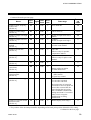
Do not set this one
LG MASTER-K series special protocol
See PLC Communication Instruction Manual
[For LG PLC] (IMS01J06-E ).
ON
ON
OFF
ON
LG GLOFA-GM series special protocol
See PLC Communication Instruction Manual
[For LG PLC] (IMS01J06-E ).
OFF
ON
OFF
ON
OFF
OFF
ON
ON
ON
ON
ON
ON
ON
ON
ON
ON
Do not set this one
Factory set value: RKC communication protocol
* This is the dedicated to current transformer (CT) monitor. This protocol cannot be used
together with other protocols on the same line.
IMS01J02-E1
45
5. SETTINGS BEFORE OPERATION
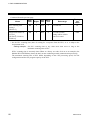
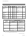
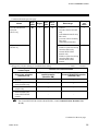
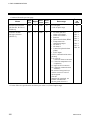
COM.PORT3 setting switch (SW3)
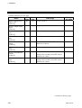
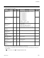
SW3
1
OFF
ON
OFF
ON
2
OFF
OFF
ON
ON
Data bit configuration
Data 8-bit, Without parity, Stop 1-bit
Data 7-bit, Odd parity, Stop 1-bit
Data 7-bit, Even parity, Stop 1-bit
Data 7-bit, Even parity, Stop 2-bit
Factory set value: Data 8-bit, Without parity, Stop 1-bit
SW3
3
OFF
ON
OFF
ON
4
OFF
OFF
ON
ON
Communication speed
9600 bps
19200 bps
38400 bps
Don't set this one
Factory set value: 9600 bps
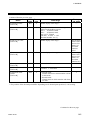
SW3
5
OFF
Protocol
RKC communication protocol
(Based on ANSI X3.28 subcategory 2.5 B1)
See 6. RKC COMMUNICATION (P. 52).
ON
Modbus protocol
See 7. MODBUS (P. 109).
Factory set value: RKC communication protocol
SW3
Initialize
6
OFF Normal (It is initialized only in initialization execution)
ON In power on, all module is initialized
Factory set value: Normal (It is initialized only in initialization execution)
Continued on the next page.
46
IMS01J02-E1
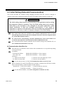
5. SETTINGS BEFORE OPERATION
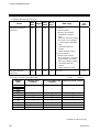
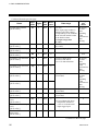
COM.PORT3 setting switch (SW3)
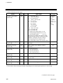
SW3
7
OFF
ON
Modbus mode selection
Modbus mode 1
(Data time interval judges time-out with 24-bit time or more.)
This mode is based on Modbus RTU standard.
Modbus mode 2
(Data time interval judges time-out with 24-bit time + 2 ms or more.)
As time intervals between each data configuring one message become longer
than the 24-bit time when sending a command message from the master, it is set
when the slave does not make a response.
(When MONITOUCH V6 series manufactured by Hakko Electronics Co., Ltd.
is used. )
Factory set value: Modbus mode 1
The setting of Modbus mode selection is valid for the communication ports of
COM.PORT1/COM.PORT2 and COM.PORT3. However, the setting of
COM.PORT3 setting switch (SW3) No.7 is invalid for any communication ports
which select protocols other than the Modbus protocol.
Always do not change the COM.PORT3 setting switch (SW3) No. 8.
IMS01J02-E1
47
5. SETTINGS BEFORE OPERATION
5.2 Unit Address Setting
When each control unit is multi-drop connected to host computer, set the unit address of each control
unit using the unit address setting switch at the front of the H-PCP-J module. For this setting, use a
small blade screwdriver.
Unit address setting switch
456
CD
AB E
23
F01
7 89
Setting range:
0 to 15 (0 to F: hexadecimal)
H-PCP-J module
Set the unit address such that it is different to the other addresses on the same line.
Otherwise, problems or malfunction may result.
48
IMS01J02-E1
5. SETTINGS BEFORE OPERATION
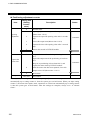
5.3 Start-up Procedures
Check prior to power on
Check the following items before turning on the power to the control unit.
Operation environments conform to 3.1 Mounting Cautions (P. 20).
Wiring and connections conform to 4. WIRING (P. 25).
Power supply voltage conforms to 2. SPECIFICATIONS (P. 14).
Check after power on
Check that the RUN lamps on the H-PCP-J and function modules are flashing.
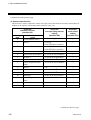
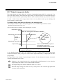
Operation after power on
Action after power on differs depending on control RUN/STOP holding (Identifier X1) setting.
Control RUN/STOP
holding
(Identifier X1)
0: Not hold
1: Hold
Status after power-ON
Operation mode
Control RUN/STOP
Same as mode before the power
failure
“0: Control STOP”
Same as mode before the power
failure
Same as status before the power
failure
Stopped until “1: Control RUN”
is instructed from the PLC or host
computer.
Control before power failure is
maintained even if no PLC or
host computer is connected.
2: Start-up from control run
status
“1: Monitor” mode
“1: Control RUN”
However if the operation mode is
set to “0: Unused,” “0: Unused”
remains unchanged.
However, no control is performed
until the operation mode is set to
“3: Normal (perform control).”
For the control RUN/STOP holding (Identifier X1), see the 6.3 Initial Settings (P. 81).
IMS01J02-E1
49
5. SETTINGS BEFORE OPERATION
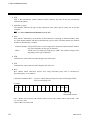
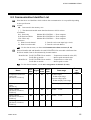
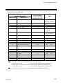
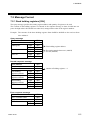
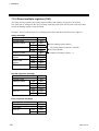
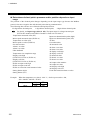
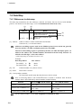
5.4 Communication Requirements
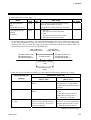
Processing times during data send/receive
The SR Mini HG SYSTEM requires the following processing times during data send/receive.
Whether the host computer is using either the polling or selecting procedure for communication, the
following processing times are required for SR Mini HG SYSTEM to send data:
-Response wait time after SR Mini HG SYSTEM sends BCC in polling procedure
-Response wait time after SR Mini HG SYSTEM sends ACK or NAK in selecting procedure
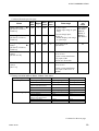
RKC communication (Polling procedure)
Procedure details
Time (ms)
MIN
TYP
MAX
Response send time after SR Mini HG SYSTEM receives ENQ
4
7
20
Response send time after SR Mini HG SYSTEM receives ACK
4
−
20
Response send time after SR Mini HG SYSTEM receives NAK
4
−
20
Response wait time after SR Mini HG SYSTEM sends BCC
−
−
1.0
RKC communication (Selecting procedure)
Procedure details
Time (ms)
MIN
TYP
MAX
Response send time after SR Mini HG SYSTEM receives BCC
4
7
20
Response wait time after SR Mini HG SYSTEM sends ACK
−
−
1.0
Response wait time after SR Mini HG SYSTEM sends NAK
−
−
1.0
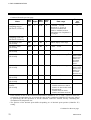
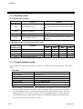
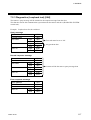
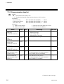
Modbus
Procedure details
Time
Read holding registers [03H]
Response transmission time after the slave receives the query message
20 ms max.
Preset single register [06H]
Response transmission time after the slave receives the query message
10 ms max.
Diagnostics (loopback test) [08H]
Response transmission time after the slave receives the query message
10 ms max.
Preset multiple register [10H]
Response transmission time after the slave receives the query message
40 ms max.
Only 1 port uses communication port, and response send time is time at having set interval
time in 0 ms. In addition, in status of the following, there is not communication between a
little.
AT end: About 0.8 seconds
Setting of initial setting item: About 0.8 to 3 seconds
50
IMS01J02-E1
5. SETTINGS BEFORE OPERATION
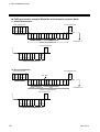
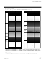
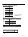
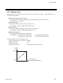
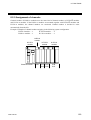
RS-485 (2-wire system) send/receive timing
The sending and receiving of RS-485 communication is conducted through two wires; consequently,
the transmission and reception of data requires precise timing. Typical polling and selecting
procedures between the host computer and SR Mini HG SYSTEM are described below:
Polling procedure
Send data
(Possible/Impossible)
Host computer
Possible
Impossible
E
O
T
Sending status
SR Mini HG
SYSTEM
Send data
(Possible/Impossible)
-----
A
C
K
E
N
Q
Possible
a
b
N
or A
K
c
Impossible
S
T
X
Sending status
-----
B
C
C
a: Response send time after SR Mini HG SYSTEM receives [ENQ] + Interval time
b: Response wait time after SR Mini HG SYSTEM sends BCC
c: Response send time after SR Mini HG SYSTEM receives [ACK] + Interval time or
Response send time after SR Mini HG SYSTEM receives [NAK] + Interval time
Selecting procedure
Send data
(Possible/Impossible)
Host computer
Possible
Impossible
S
T
X
Sending status
SR Mini HG
SYSTEM
Send data
(Possible/Impossible)
Sending status
Possible
-----
B
C
C
a
b
Impossible
A
N
C or A
K
K
a: Response send time after SR Mini HG SYSTEM receives BCC + Interval time
b: Response wait time after SR Mini HG SYSTEM sends ACK or
Response wait time after SR Mini HG SYSTEM sends NAK
To switch the host computer from transmission to reception, send data must be on line. To
check if data is on line, do not use the host computer’s transmission buffer but confirm it by
the shift register.
Whether the host computer is using either the polling or selecting procedure for
communication, the following processing times are required for SR Mini HG SYSTEM to
send data:
-Response wait time after SR Mini HG SYSTEM sends BCC in polling procedure
-Response wait time after SR Mini HG SYSTEM sends ACK or NAK in selecting
procedure
Fail-safe
A transmission error may occur with the transmission line disconnected, shorted or set to the
high-impedance state. In order to prevent the above error, it is recommended that the fail-safe function
be provided on the receiver side of the host computer. The fail-safe function can prevent a framing
error from its occurrence by making the receiver output stable to the MARK (1) when the transmission
line is in the high-impedance state.
IMS01J02-E1
51
6. RKC COMMUNICATION
6.1 Protocol
RKC communication uses the polling/selecting method to establish a data link. The basic procedure is
followed ANSI X3.28 subcategory 2.5, B1 basic mode data transmission control procedure (Fast
selecting is the selecting method used in SR Mini HG SYSTEM).
• The polling/selecting procedures are a centralized control method where the host computer controls
the entire process. The host computer initiates all communication so the controller responds
according to queries and commands from the host.
• The code use in communication is 7-bit ASCII code including transmission control characters.
Transmission control characters used in SR Mini HG SYSTEM:
EOT (04H), ENQ (05H), ACK (06H), NAK (15H), STX (02H), ETB (17H), ETX (03H)
( ): Hexadecimal
6.1.1 Polling
Polling is the action where the host computer requests one of the connected SR Mini HG SYSTEM to
transmit data. An example of the polling procedure is shown below:
Host computer send
E
O
T
E
[Address] [ ID ] N
Q
(1)
(2)
SR Mini HG SYSTEM send
Host
computer
send
SR Mini HG Host
SYSTEM computer
send
send
E
O
T
No response
(5)
(10)
E
O
T (4)
S
E E
T [ ID ] [ Data ] T or T [ BCC ]
X
B X
(3)
No (8)
response
(9)
Time
out
E
O
T
Indefinite
A (6)
C
K
N
A
(7) K
ID: Identifier
52
IMS01J02-E1
6. RKC COMMUNICATION
Polling procedures
(1) Data link initialization
Host computer sends EOT to the controllers to initiate data link before polling sequence.
(2) Data sent from host computer - Polling sequence
Host computer sends polling sequence with the format shown below:
1.
2.
Example:
3.
ENQ
0
2
M
1
ENQ
Address Identifier
1. Address (2 digits)
This data is a unit address of the SR Mini HG SYSTEM for polled and must be the same as the
unit address set value in item 5.2 Unit Address Setting (P. 48).
2. Identifier (2 digits)
The identifier specifies the type of data that is requested from the SR Mini HG SYSTEM.
Always attach the ENQ code to the end of the identifier.
See 6.2 Communication Identifier List (P. 65).
3. ENQ
The ENQ is the transmission control character that indicates the end of the polling sequence. The
host computer then must wait for a response from the SR Mini HG SYSTEM.
(3) Data sent from the SR Mini HG SYSTEM
If the polling sequence is received correctly, the SR Mini HG SYSTEM sends data in the following
format:
1.
2.
3.
4.
6.
STX
Identifier
Data
ETB
BCC
3.
5.
6.
Data
ETX
BCC
or
1.
STX
2.
Identifier
If the length of send data (from STX to BCC) exceeds 128 bytes, it is divided into blocks by
ETB. In this case, the succeeding divided data is sent after STX.
IMS01J02-E1
53
6. RKC COMMUNICATION
1. STX
STX is the transmission control character which indicates the start of the text transmission
(identifier and data).
2. Identifier (2 digits)
The identifier indicates the type of data (measured value, status and set value) sent to the host
computer.
See 6.2 Communication Identifier List (P. 65).
3. Data
Data which is indicated by an identifier of this instrument, consisting of channel numbers, data,
etc. Each channel number and data are delimited by a space (20H). The data and the next channel
number are delimited by a comma.
• Channel number: 2-digit ASCII code, not zero-suppressed. Channels without channel numbers
may exist depending on the type of identifier.
• Data:
ASCII code, zero-suppressed with spaces (20H). The number of digits varies
depending on the type of identifier.
4. ETB
Transmission control character indicating the end of the block.
5. ETX
Transmission control character indicating the end of the text.
6. BCC
BCC (Block Check Character) detects error using horizontal parity and is calculated by
horizontal parity (even number).
Calculation method of BCC: Exclusive OR all data and characters from STX through ETB or
ETX, not including STX.
Example:
STX
M
1
0
1
1
5
0
.
0
ETX BCC
4DH 31H 30H 31H 20H 20H 31H 35H 30H 2EH 30H 03H
Hexadecimal numbers
BCC = 4DH ⊕ 31H ⊕ 30H ⊕ 31H ⊕ 20H ⊕ 20H ⊕ 31H ⊕ 35H ⊕ 30H ⊕ 2EH ⊕ 30H ⊕ 03H = 54H
( ⊕: Exclusive OR)
Value of BCC becomes 54H
54
IMS01J02-E1
6. RKC COMMUNICATION
(4) EOT send (Ending data transmission from the SR Mini HG SYSTEM)
In the following cases, the SR Mini HG SYSTEM sends EOT to terminate the data link:
• When the specified identifier is invalid
• When there is an error in the data format
• When all the data has been sent
(5) No response from the SR Mini HG SYSTEM
The SR Mini HG SYSTEM will not respond if the polling address is not received correctly. It may be
necessary for the host computer to take corrective action such as a time-out.
(6) ACK (Acknowledgment)
An acknowledgment ACK is sent by the host computer when data received is correct. When the SR
Mini HG SYSTEM receives ACK from the host computer, the SR Mini HG SYSTEM will send any
remaining data of the next identifier without additional action from the host computer.
For the identifier, see 6.2 Communication Identifier List (P. 65).
When host computer determines to terminate the data link, EOT is sent from the host computer.
(7) NAK (Negative acknowledge)
If the host computer does not receive correct data from the SR Mini HG SYSTEM, it sends a negative
acknowledgment NAK to the SR Mini HG SYSTEM. The SR Mini HG SYSTEM will re-send the
same data when NAK is received. This cycle will go on continuously until either recovery is achieved
or the data link is corrected at the host computer.
(8) No response from host computer
When the host computer does not respond within approximately three seconds after the SR Mini HG
SYSTEM sends data, the SR Mini HG SYSTEM sends EOT to terminate the data link (time-out time:
about 3 seconds).
(9) Indefinite response from host computer
The SR Mini HG SYSTEM sends EOT to terminate the data link when the host computer response is
indefinite.
(10) EOT (Data link termination)
The host computer sends EOT message when it is necessary to suspend communication with the
SR Mini HG SYSTEM or to terminate the data link due lack of response from the SR Mini HG
SYSTEM.
IMS01J02-E1
55
6. RKC COMMUNICATION
Polling procedure example (When the host computer requests data)
Normal transmission
Host computer send
E
O
T
0
1
S
Host computer send
E
N
Q
1
A
C
K
04H 30H 31H 53H 31H 05H
S
T
X
Address Identifier
S
1
0
1
4
0
0
.
0
…
02H 53H 31H 30H 31H 20H 20H 34H 30H 30H 2EH 30H
Identifier Channel No.
E
T
X
B
C
C
06H
03H 67H
Data
Continue to *1
SR Mini HG SYSTEM send
Host computer send
*1
E
O
T
S
T
X
P
1
0
…
1
02H 50H 31H 30H 31H 20H
E
T
X
B
C
C
04H
03H 48H
SR Mini HG SYSTEM send
Error transmission
Host computer send
E
O
T
0
1
S
1
Host computer send
E
N
Q
N
A
K
Error data
04H 30H 31H 53H 31H 05H
S
T
X
Address Identifier
S
1
0
1
4
02H 53H 31H 30H 31H 20H
Identifier
0
0
.
0
34H 30H 30H 2EH 30H
Data
Channel No.
…
E
T
X
B
C
C
15H
03H 68H
Continue to *1
SR Mini HG SYSTEM send
Host computer send
*1
E
O
T
S
T
X
S
1
0
1
02H 53H 31H 30H 31H 20H
…
E
T
X
B
C
C
04H
03H 67H
SR Mini HG SYSTEM resend
56
IMS01J02-E1
6. RKC COMMUNICATION
6.1.2 Selecting
Selecting is the action where the host computer requests one of the connected SR Mini HG SYSTEM
to receive data. An example of the selecting procedure is shown below:
Host computer send
SR Mini HG SYSTEM
send
E
O
T
(1)
[Address]
S
E
E
T [ID] [ Data ] T or T [ BCC ]
X
B
X
(2)
(3)
No response
(6)
A
C
K (4)
N
A
K
Host
computer
send
E
O
T
(7)
(5)
ID: Identifier
Selecting procedures
(1) Data link initialization
Host computer sends EOT to the SR Mini HG SYSTEM to initiate data link before selecting sequence.
(2) Sending selecting address from the host computer
Host computer sends selecting address for the selecting sequence.
Address (2 digits):
This data is a unit address of the SR Mini HG SYSTEM to be selected and must be the same as the
unit address set value in item 5.2 Unit Address Setting (P. 48).
IMS01J02-E1
57
6. RKC COMMUNICATION
(3) Data sent from the host computer
The host computer sends data for the selecting sequence with the following format:
1.
STX
2.
Identifier
3.
4.
6.
Data
ETB
BCC
3.
5.
6.
Data
ETX
BCC
or
1.
STX
2.
Identifier
If the length of send data (from STX to BCC) exceeds 128 bytes, it is divided into blocks by
ETB. In this case, the succeeding divided data is sent after STX.
Details for 1 to 6, see 6.1.1 Polling (P. 52).
(4) ACK (Acknowledgment)
An acknowledgment ACK is sent by the SR Mini HG SYSTEM when data received is correct. When
the host computer receives ACK from the SR Mini HG SYSTEM, the host computer will send any
remaining data. If there is no more data to be sent to SR Mini HG SYSTEM, the host computer sends
EOT to terminate the data link.
(5) NAK (Negative acknowledge)
If the SR Mini HG SYSTEM does not receive correct data from the host computer, it sends a negative
acknowledgment NAK to the host computer. Corrections, such as re-send, must be made at the host
computer. The SR Mini HG SYSTEM will send NAK in the following cases:
• When an error occurs on communication the line (parity, framing error, etc.)
• When a BCC check error occurs
• When the specified identifier is invalid
• When receive data exceeds the setting range
(6) No response from SR Mini HG SYSTEM
The SR Mini HG SYSTEM does not respond when it can not receive the selecting address, STX, ETB,
ETX or BCC.
(7) EOT (Data link termination)
The host computer sends EOT when there is no more data to be sent from the host computer or there is
no response from the SR Mini HG SYSTEM.
58
IMS01J02-E1
6. RKC COMMUNICATION
Selecting procedure example (when the host computer sends data)
Normal transmission
Host computer send
E
O
T
0
1
S
T
X
S
1
0
1
4
0
0
.
0
…
04H 30H 31H 02H 53H 31H 30H 31H 20H 20H 34H 30H 30H 2EH 30H
Identifier Channel No.
Address
E
T
X
B
C
C
03H 57H
Data
A
C
K
06H
Host computer send
*1
S
T
X
P
1
0
1
Host computer send
E
T
X
…
02H 50H 31H 30H 31H 20H
B
C
C
03H 49H
SR Mini HG
SYSTEM send
Continue to *1
E
O
T
A
C
K
04H
06H
SR Mini HG
SYSTEM send
Error transmission
Error data
Host computer send
E
O
T
0
1
S
T
X
S
1
0
1
4
0
0
.
0
04H 30H 31H 02H 53H 31H 30H 31H 20H 20H 34H 30H 30H 2EH 30H
Identifier Channel No.
Address
…
E
T
X
B
C
C
03H 56H
Data
N
A
K
15H
Host computer resend
*1
S
T
X
S
1
0
1
02H 53H 31H 30H 31H 20H
…
Host computer send
E
T
X
B
C
C
03H 57H
SR Mini HG
SYSTEM send
Continue to *1
E
O
T
A
C
K
04H
06H
SR Mini HG
SYSTEM send
IMS01J02-E1
59
6. RKC COMMUNICATION
6.1.3 Communication data structure
Data description (Transmission/receive data structure)
S
T
X
E B
T C
X C
........................................................................................................
Data
Part of the data above is shown below.
Data for each channel
Data length 6 digits
0 1
1 0 0
.
Data
Identifier Channel
No.
Space
0
,
0 2
Channel
No.
Comma
Space
...
Data
...
2 0
Channel
No.
Space
...
Data
Data length 1 digit
0 1
,
0 2
Channel
Data
Identifier Channel
Data
No.
No.
Space Comma
Space
...
2 0
Channel
Data
No.
Space
By data structure, channel number becomes as follows:
Data for each module:
Module number
Data for each event input logic circuit: Event input logic circuit number
Data for each unit address (Without channel)
Data length 1 digit
Identifier Data
60
Data length 6 digits
Identifier
Data
IMS01J02-E1
6. RKC COMMUNICATION
6.1.4 Examples of polling and selecting check programs
The following is the sample program for NEC PC-9800 series computers in BASIC language for
carrying out polling and selecting checking by RS-232C specification. There will be some differences
in the computer languages according to the type of computer. Before executing the program, confirm
that there is no mistake in the wiring of the communications cable and check that the control unit data
bit configuration is set to 8 for data bit and Without for parity bit. In addition, the communications
speed setting should be set to match the host computer speed setting.
Example of temperature set values polling check program
1000 '-------------------- Identifier setting ---------------------1010 ID$="S1"
1020 '
1030 '--------------- Communications initial setting --------------1040 CM$="N81NN"
1050 INPUT "Control unit address=";ADD$
1060 STX$=CHR$(&H2) : EOT$=CHR$(&H4) : ENQ$=CHR$(&H5)
1070 ACK$=CHR$(&H6) : NAK$=CHR$(&H15): ETX$=CHR$(&H3)
1080 OPEN "COM1:"+CM$ AS #1
1090 CONSOLE ,,,1
1100 COLOR 7:CLS 3
1110 '
1120 '------------------ Program main routine --------------------1130 *POL
1140
PRINT "
(Polling check)
"
1150
PRINT "*********Receiving the set values************"
1160
PRINT "
1170
DT$=EOT$+ADD$+ID$+ENQ$
1180
GOSUB *TEXT
1190
GOSUB *RXDT
1200 '
1210 *J10
1220
J=0
1230 '
1240 *IF1
1250
IF LOC(1)=0 THEN J=J+1:IF J<500 THEN *IF1 ELSE PRINT "
TIME OUT ":END
1260 '
1270
K$=INPUT$(1,#1)
1280
IF K$=ETX$ GOTO *ETXRX
1290
IF K$=NAK$ THEN PRINT " NAK":END
1300
IF K$=EOT$ THEN PRINT "
EOT":END
1310
IF K$=ACK$ THEN PRINT " ACK":END
1
Identifier setting
Communications data configuration setting
Control unit address input
Communications character setting
Open RS-232C circuit
Data configuration setting
Setting of the receiving waiting time 1
(Timeout processing)
Communications condition checking
Setting of the receiving waiting time:
If time out occurs in using high speed computer (Except no response), the numeral value of 500 in
the program should be changed to an appropriately-sized numeral value.
Continued on the next page.
IMS01J02-E1
61
6. RKC COMMUNICATION
1320 '
1330
DT$=DT$+K$
1340
GOTO *J10
1350 '
1360 *ETXRX
1370
DT$=DT$+K$
1380
BCCRX$=INPUT$(1,#1)
1390
BCCRX=ASC(BCCRX$)
1400
GOSUB *BCCCH
1410
IF BCC<>BCCRX THEN GOSUB *NAKTX
1420
IF BCC<>BCCRX THEN GOSUB *RXDT: GOTO *J10
1430 '
1440
PRINT "Data has been correctly received"
1450
PRINT "Received data=";DT$ : END
1460 '
1470 '--------------------- Sub-routine ---------------------1480 '
1490 *NAKTX
1500
PRINT "BCC error"
1510
DT$=NAK$
1520
GOSUB *TEXT
1530
RETURN
1540 '
1550 *RXDT
1560
DT$=""
1570
RETURN
1580 '
1590 *TEXT
1600
PRINT #1,DT$;
1610
RETURN
1620 '
1630 *BCCCH
1640
FOR II=1 TO LEN(DT$)
1650
BCCA$=MID$(DT$,II,1)
1660
IF BCCA$=STX$ THEN BCC=0 : GOTO *IINEXT
1670
BCC=BCC XOR ASC(BCCA$)
1680 *IINEXT
1690
NEXT II
1700
RETURN
62
BCC checking
Display of received data and
closing of RS-232C circuit
Processing on occurrence of a BCC error
Clearing of circuit buffer
Transfer of polling identifier
BCC calculation
IMS01J02-E1
6. RKC COMMUNICATION
Example of temperature set values selecting checking program
1000 '-------------------- Identifier setting ---------------------1010 ID$="S1"
1020 '
1030 '--------------- Communications initial setting --------------1040 CM$="N81NN"
1050 STX$=CHR$(&H2) : EOT$=CHR$(&H4) : ENQ$=CHR$(&H5)
1060 ACK$=CHR$(&H6) : NAK$=CHR$(&H15): ETX$=CHR$(&H3)
1070 OPEN "COM1:"+CM$ AS #1
1080 CONSOLE ,,,1
1090 COLOR 7:CLS 3
1100 '
1110 '------------------ Program main routine --------------------1120 *SEL
1130
PRINT "
(Selection check)
"
1140
PRINT "********Transmission of set values*********"
1150
PRINT "
1160
INPUT "Unit No.=";ADD$:INPUT "Channel No.=";C$
:INPUT "Set value=";S$
1170
DT$=EOT$+ADD$+STX$+ID$+C$+" "+S$+ETX$
1180
PRINT "Transmitting data=";DT$
1190
GOSUB *BCCCH
1200
DT$=DT$+CHR$(BCC)
1210
GOSUB *TEXT
1220
GOSUB *RXDT
1230 '
1240 *J20
1250
J=0
1260 '
1270 *IF2
1280
IF LOC(1)=0 THEN J=J+1:IF J<500 THEN *IF2 ELSE PRINT "
TIME OUT ":END
1290 '
1300
K$=INPUT$(1,#1)
1310
IF K$=NAK$ THEN PRINT " NAK":END
1320
IF K$=ACK$ THEN PRINT "Control unit has received the data"
:END
1330 '
1340 '
1350 '
1
Identifier setting
Communications data configuration setting
Communications character setting
Opening of RS-232C circuit
Input of the unit and channel number,
and the temperature set value
Data configuration setting 1
Display of transmitting data
Data configuration setting 2
Setting of the receiving waiting time 1
(Timeout processing)
Communications condition check,
Display of communication result,
and closing of RS-232C circuit
Setting of the receiving waiting time:
If time out occurs in using high speed computer (Except no response), the numeral value of 500 in
the program should be changed to an appropriately-sized numeral value.
Continued on the next page.
IMS01J02-E1
63
6. RKC COMMUNICATION
1360 '--------------------- Sub-routine ---------------------1370 '
1380 *RXDT'
1390
DT$=""
1400
RETURN
1410 '
1420 *TEXT
1430
PRINT #1,DT$;
1440
RETURN
1450 '
1460 *BCCCH
1470
FOR II=1 TO LEN(DT$)
1480
BCCA$=MID$(DT$,II,1)
1490
IF BCCA$=STX$ THEN BCC=0 : GOTO *IINEXT
1500
BCC=BCC XOR ASC(BCCA$)
1510 *IINEXT
1520
NEXT II
1530
RETURN
64
Clearing of circuit buffer
Transfer of selection data
BCC calculation
IMS01J02-E1
6. RKC COMMUNICATION
6.2 Communication Identifier List
Note that there are identifiers which indicate that communication is not possible depending
on the specification.
• Name
: Item stored in the memory area.
[ ]: The functional module name that data becomes valid is written.
• Attributes
RO: Read only
SR Mini HG SYSTEM → Host computer
R/W: Read and Write
SR Mini HG SYSTEM ↔ Host computer
WO: Write only
SR Mini HG SYSTEM ← Host computer
• Structure
C: Data for each channel
L: Data for each event input logic circuit
M: Data for each module
U: Data for each unit address
For the data structure, see the 6.1.3 Communication data structure (P. 60).
Data of identifier M1 and identifier S1 with H-TIO- /H-CIO-A module is different from
H-SIO-A module. Data is discriminated by channel number.
Identifier M1: For H-TIO- /H-CIO-A module...... Temperature measured value (PV)
For H-SIO-A module ..................... Motor speed measured value
Identifier S1: For H-TIO- /H-CIO-A module...... Temperature set value (SV)
For H-SIO-A module ..................... Motor speed set value
For the channel number, see the 8.2.9 Assignment of channels (P. 183).
Name
Temperature measured
value (PV)
[H-TIO- , H-CIO-A]
IdenAttri- StrucDigits
tifier
bute ture
M1
6
RO
C
Motor speed measured
value
[H-SIO-A]
Data range
Factory
set
value
TC/RTD input:
Within input range
Current/voltage input:
Within display scale range
Within display scale range
Alarm 1 status
[H-TIO- , H-CIO-A,
H-SIO-A]
AA
1
RO
C
0: OFF
1: ON
Alarm 2 status
[H-TIO- , H-CIO-A,
H-SIO-A]
AB
1
RO
C
0: OFF
1: ON
Burnout status
[H-TIO- , H-CIO-A,
H-SIO-A]
B1
1
RO
C
0: OFF
1: ON
Continued on the next page.
IMS01J02-E1
65
6. RKC COMMUNICATION
Continued from the previous page.
Name
IdenAttri- StrucDigits
tifier
bute ture
Data range
Factory
set
value
Heat-side manipulated
output value
[H-TIO- , H-CIO-A]
O1
6
RO
C
−5.0 to +105.0 %
Cool-side manipulated
output value
[H-TIO- , H-CIO-A]
O2
6
RO
C
−5.0 to +105.0 %
Heater break alarm status
[H-TIO-A/C/D, H-CIO-A]
AC
1
RO
C
0: OFF
Current transformer input
measured
value 1
[H-TIO-A/C/D]
M3
6
RO
C
0.0 to 100.0 A or
0.0 to 30.0 A
Current transformer input
measured
value 2
[H-CT-A]
M4
Set value monitor
[H-TIO- , H-CIO-A,
H-SIO-A]
MS
Temperature rise
completion status
[H-TIO- , H-CIO-A]
HE
1
RO
U
0: Rise not complete
1: Rise completed
Error code
[H-PCP-J]
ER
1
RO
U
0: Operations normal
1: Backup data check error
2: RAM read/write error
3: System structure error
4: Internal communications
error
5: A/D converter error
6: Adjustment data error
1: ON
Current transformer (CT)
input measured value of the
H-TIO-A/C/D module.
6
RO
C
0.0 to 100.0 A or
0.0 to 30.0 A
Current transformer (CT)
input measured value of the
H-CT-A module.
6
RO
C
TC/RTD input:
Within input range
Current/voltage input,
H-SIO-A:
Within display scale range
Continued on the next page.
66
IMS01J02-E1
6. RKC COMMUNICATION
Continued from the previous page.
Name
PID/AT transfer *
[H-TIO- , H-CIO-A,
H-SIO-A]
Identifier
Digits
G1
1
Attri- Strucbute
ture
R/W
C
Data range
Factory
set
value
0: PID control operation
1: AT (Autotuning) operation
0
* Autotuning (AT) is the function which automatically measures, calculates and sets the optimum PID
constants according to the set temperature.
Caution for using the Autotuning (AT)
When a temperature change (UP and/or Down) is 1C or less per minute during
Autotuning, Autotuning may be cancelled before calculating PID values. In that case,
adjust the PID values manually. It is possible to happen when the set value is around
the ambient temperature or is close to the maximum temperature achieved by the load.
The following is the conditions necessary to carry out autotuning and the conditions which will cause
the autotuning to stop.
Conditions necessary for autotuning:
The autotuning should be executed after satisfying all of the following conditions:
• Operation mode conditions:
− Auto/Manual transfer (Identifier J1)
→ Auto mode
− PID/AT transfer (Identifier G1)
→ PID control mode
− Control RUN/STOP transfer (Identifier SR) → Control RUN mode
• The measured value (PV) is without input error range [Input error determination point (high) >
Measured value (PV) > Input error determination point (low)].
• The output limiter high limit should be more than 0.1 % and the output limiter low limit should be
less than 99.9 %.
• When operation mode is set to “Normal (Can be controlled ).”
When the autotuning is finished, the display of each channel automatically returns to “0: PID control
operation.”
Conditions which will cause the autotuning to stop:
• When the temperature set value (SV) is changed.
• When the memory area is changed.
• When the PV bias value is changed.
• When the AT bias value is changed.
• When transfer to Manual mode using the Auto/Manual transfer.
• When the measured value (PV) goes to input error range [Measured value (PV) ≥ Input error
determination point (high) or Input error determination point (low) ≥ Measured value (PV)].
• When the power is cut off.
• When FAIL occurs in the module whose channel is under the autotuning. Otherwise, when FAIL
occurs in the H-PCP-J module.
• When transfer to the PID control mode by the PID/AT transfer.
• When operation mode is set to “Unused,” “Monitor” or “Alarm.”
• When the Control RUN/STOP function is changed to the “Control STOP” function.
When the above-mentioned conditions to stop the autotuning occurs, the autotuning is
immediately stopped and switch over to the PID control mode. The PID constants
return to the values at the start of the autotuning.
Continued on the next page.
IMS01J02-E1
67
6. RKC COMMUNICATION
Continued from the previous page.
Name
Temperature set value
(SV)
[H-TIO- , H-CIO-A]
IdenAttri- StrucDigits
tifier
bute ture
S1
6
R/W
C
Motor speed set value
[H-SIO-A]
Data range
Factory
set
value
TC/RTD input:
Within input range
(Within setting limiter)
Current/voltage input:
Within display scale range
(Within setting limiter)
0a
Within display scale range
(Within setting limiter)
0a
Heat-side proportional
band
[H-TIO- , H-CIO-A,
H-SIO-A]
P1
6
R/W
C
0.1 to 1000.0 % of span
H-TIO- ,
H-CIO-A:
3.0
H-SIO-A:
300.0
Cool-side proportional
band
[H-TIO- , H-CIO-A]
P2
6
R/W
C
0.1 to 1000.0 % of span
3.0
Integral time
[H-TIO- , H-CIO-A,
H-SIO-A]
I1
6
R/W
C
1 to 3600 seconds
H-TIO- ,
H-CIO-A:
240
H-SIO-A:
2
Derivative time
[H-TIO- , H-CIO-A,
H-SIO-A]
D1
6
R/W
C
0 to 3600 seconds
(0: PI action)
H-TIO- ,
H-CIO-A:
60
H-SIO-A:
0
Overlap/deadband
[H-TIO- , H-CIO-A]
V1
6
R/W
C
−10.0 to +10.0 % of span
0.0
Control response
parameters
[H-TIO- , H-CIO-A,
H-SIO-A]
CA
1
R/W
C
0: Slow
0b
1: Medium 2: Fast
In order to perform PID control
by using the fuzzy function,
specify “Fast.” The fuzzy
function is effective to restrict
overshoot or undershoot
occurring at operation start, or
resulting from set value
changes.
(Fuzzy function correspond to
H-TIO-P/R module only.)
a
The position of the decimal point differs depending on the input range.
b
Heat control (H-TIO- /H-CIO-A): 0
Position proportioning control (H-TIO-K): 0
Heat/cool control (H-TIO- /H-CIO-A): 2
Speed control (H-SIO-A): 0
Continued on the next page.
68
IMS01J02-E1
6. RKC COMMUNICATION
Continued from the previous page.
Name
IdenAttri- StrucDigits
tifier
bute ture
Data range
Factory
set
value
See Factory
set value
table of
Alarm 1/
Alarm 2
set value *
Alarm 1 set value
[H-TIO- , H-CIO-A,
H-SIO-A]
A1
6
R/W
C
Alarm 2 set value
[H-TIO- , H-CIO-A,
H-SIO-A]
A2
6
R/W
C
Setting change rate
limiter
[H-TIO- , H-CIO-A,
H-SIO-A]
HH
6
R/W
C
0.0 to 100.0 % of
span/minute
0.0
Heater break alarm set
value 1
[H-TIO-A/C/D]
A3
6
R/W
C
0.0 to 100.0 A or
0.0 to 30.0 A
0.0
Heater break alarm set
value 2
[H-CT-A]
A4
TC/RTD input:
Within input range or span
range
Current/voltage input,
H-SIO-A:
Within display scale range
or span range
For the current transformer
(CT) input of the
H-TIO-A/C/D module.
6
R/W
0.0 to 100.0 A or
0.0 to 30.0 A
C
0.0
For the current transformer
(CT) input of the H-CT-A
module.
* Factory set value table of Alarm 1/Alarm 2 set value
Input type
TC/RTD input
Current/voltage input
Alarm type
Process high alarm
Process low alarm
Deviation high alarm, Deviation
high/low alarm, Band alarm
Deviation low alarm
No alarm function
Process high alarm
Process low alarm
Deviation high alarm, Deviation
high/low alarm, Band alarm
Deviation low alarm
No alarm function
Alarm 1 set value
Input range (high limit)
Input range (low limit)
50 °C
Alarm 2 set value
Input range (high limit)
Input range (low limit)
50 °C
−50 °C
Input range (high limit)
100.0 %
0.0 %
50 %
−50 °C
Input range (low limit)
100.0 %
0.0 %
50 %
−50 %
100.0 %
−50 %
0.0 %
Continued on the next page.
IMS01J02-E1
69
6. RKC COMMUNICATION
Continued from the previous page.
Name
IdenAttri- StrucDigits
tifier
bute ture
Data range
Factory
set
value
Operation mode transfer
[H-TIO- , H-CIO-A,
H-SIO-A]
EI
1
R/W
C
Heat-side proportioning
cycle time
[H-TIO- , H-CIO-A]
T0
6
R/W
C
Cool-side proportioning
cycle time
[H-TIO- , H-CIO-A]
T1
6
R/W
C
1 to 100 seconds
Setting will be invalid in
current/voltage output and heat
control.
20 a
PV bias
[H-TIO- , H-CIO-A,
H-SIO-A]
PB
6
R/W
C
−5.00 to +5.00 % of span
ZK-1103 specification:
−Input span to +Input span b
0.00
Control RUN/STOP
transfer
[H-PCP-J]
SR
1
R/W
U
0: Unused
If set to “Unused,” no control,
monitor or alarm monitor is
performed.
1: Monitor
If set to “Monitor,” only the
monitor is performed. No
control or alarm monitor is
performed.
2: Alarm
If set to “Alarm,” monitor or
alarm monitor is performed.
No control is performed.
3: Normal
Selected to normal mode to
perform control, monitor or
alarm monitor.
1 to 100 seconds
Setting will be invalid in
current/voltage output.
0: Control STOP
1: Control RUN
Only when the initial set mode
is “0: Normal communication,”
control can be start.
3
20 a
ZK-1103:
0c
0
a
Relay contact output: 20 seconds
Voltage pulse output, Open collector output, Triac output: 2 seconds
b
For −Input span < −999.9 ....... Low limit value: −999.9
For −Input span < −99.99 ....... Low limit value: −99.99
For −Input span < −9.999 ....... Low limit value: −9.999
c
Unit (°C, °F, etc.) and decimal point position (No decimal place, One decimal place, Two decimal
places or Three decimal places) depends on input range type.
Continued on the next page.
70
IMS01J02-E1
6. RKC COMMUNICATION
Continued from the previous page.
Factory
set
value
Identifier
Digits
Initial setting mode
[H-PCP-J]
IN
1
R/W
U
0: Normal communication
Normal communication is
possible.
1: Extended communication a
Normal and initial setting
communication are
possible.
0
Memory area number
[H-TIO- , H-CIO-A,
H-SIO-A]
ZA
1
R/W
U
1 to 8
1
Alarm interlock release
[H-TIO- , H-CIO-A,
H-TI- , H-AI- ]
AR
1
WO
U
1: Release (1 only)
−
Auto/Manual transfer
[H-TIO- , H-CIO-A]
J1
1
R/W
U
0: Auto
0
Manual output value
[H-TIO- , H-CIO-A]
ON
Name
Attri- Strucbute
ture
Data range
1: Manual
Setting will be invalid in
ON/OFF control and
heat/cool control.
6
R/W
C
−5.0 to +105.0 %
0.0
Setting will be invalid in
ON/OFF control and
heat/cool control.
H-TIO-C/D [Z-1017 spec.]:
−105.0 to 0.0 % (cool-side)
0.0 to +105.0 % (heat-side)
Temperature rise
completion range
[H-TIO- , H-CIO-A]
a
HD
6
R/W
C
1 to 10 °C or 1 to 20 °F
10 or 20 b
If extended communication is selected, the content of each identifier described in the 6.3 Initial
Settings (Extended Communications) (P. 81) can be changed or selected.
When the control is started, it is impossible to change the settings to the extended
communications. For the change to the extended communications, the control must be
first stopped by the “Control RUN/STOP transfer (Identifier SR).”
b
TC/RTD input: 10 °C or 20 °F
Current/voltage input, H-SIO-A: 10 % of display scale
Continued on the next page.
IMS01J02-E1
71
6. RKC COMMUNICATION
Continued from the previous page.
Name
IdenAttri- StrucDigits
tifier
bute ture
Data range
Factory
set
value
Temperature rise
completion trigger 1
[H-TIO- , H-CIO-A]
HS
1
R/W
C
0: Unused 1: Used
Do not set “1: Used” in
H-TIO-H/J module and
H-SIO-A module, because
temperature rise completion is
not judged.
0
Temperature rise
completion soak time
[H-TIO- , H-CIO-A]
T3
6
R/W
U
0 to 360 minutes
0
AI measured value
[H-AI-A/B]
M5
6
RO
C
Within display scale range 2
AI alarm 1 status
[H-AI-A/B]
AD
1
RO
C
0: OFF
1: ON
AI alarm 2 status
[H-AI-A/B]
AE
1
RO
C
0: OFF
1: ON
AI alarm 1 set value
[H-AI-A/B]
A5
6
R/W
C
Within display scale range 2
AI alarm 2 set value
[H-AI-A/B]
A6
6
R/W
C
Within display scale range 2
AI zero point correction
[H-AI-A/B]
JI
1
R/W
C
0: Cancel
1: Execution
0
AI full scale correction
[H-AI-A/B]
JJ
1
R/W
C
0: Cancel
1: Execution
0
AI operation mode
transfer
[H-AI-A/B]
NJ
1
R/W
C
0: Unused mode
Neither monitor nor alarm
monitor is done in this mode.
1: Normal mode
Normal mode in which
monitor and alarm are done.
Process high
alarm: 100.0
Process low
alarm: 0.0
No alarm
function:
100.0
Process high
alarm: 100.0
Process low
alarm: 0.0
No alarm
function: 0.0
1
1
If the channel of each of the H-TIO-H/J and H-SIO-A modules is set “1: Used,” it does no reach the
completion of temperature rise. As a result, the state of this completion (Identifier HE) which is judged
by performing the OR operation of all the channels cannot be attained, thereby continuing the
incompletion of temperature rise.
2
The position of the decimal point differs depending on AI decimal point position (Identifier JU)
setting.
Continued on the next page.
72
IMS01J02-E1
6. RKC COMMUNICATION
Continued from the previous page.
Name
IdenAttri- StrucDigits
tifier
bute ture
Data range
Factory
set
value
Control loop break
alarm (LBA) status
[H-TIO- , H-CIO-A]
AP
1
RO
C
0: OFF
LBA use selection
[H-TIO- , H-CIO-A]
HP
1
R/W
C
0: Unused
LBA time
[H-TIO- , H-CIO-A]
C6
6
R/W
C
1 to 7200 seconds
480
LBA deadband
[H-TIO- , H-CIO-A]
V2
6
R/W
C
Input span
0a
AO output value
monitor
[H-AO-A/B]
M6
6
RO
C
Display scale range b
Data will be valid in manual
mode.
AO output set value
[H-AO-A/B]
S6
6
R/W
C
Display scale range b
Setting will be valid in manual
mode.
0.0
AO function selection
[H-AO-A/B]
XO
6
R/W
C
0: Unused
1: Manual mode (outputs data
given by the AO output set
value)
2: Temperature measured value
(PV)
3: Set value monitor
4: Temperature deviation value
(deviation between the
temperature measured value
and set value monitor)
5: Heat-side manipulated
output value
6: Cool-side manipulated
output value
7: AI measured value
8: TI measured value
9: Opening monitor
(2 to 9: Recorder output mode)
1
1: ON
1: Used
0
a
The position of the decimal point differs depending on the input range.
b
The position of the decimal point differs depending on AO decimal point position (Identifier JR)
setting.
Continued on the next page.
IMS01J02-E1
73
6. RKC COMMUNICATION
Continued from the previous page.
Digits
AO corresponding
channel setting
[H-AO-A/B]
OY
6
R/W
C
1 to 20 (TIO channel)
1 to 40 (AI and TI channel)
Setting will be valid in
recorder output mode.
AO zooming high limit
[H-AO-A/B]
CV
6
R/W
C
AO zooming low limit to
100.0 %
Setting will be valid in
recorder output mode.
AO zooming low limit
[H-AO-A/B]
CW
6
R/W
C
0.0 % to AO zooming high
limit
Setting will be valid in
recorder output mode.
0.0
AO zero point correction
[H-AO-A/B]
JK
6
R/W
C
−5.00 to +5.00 %
0.00
AO full scale correction
[H-AO-A/B]
JL
6
R/W
C
−5.00 to +5.00 %
0.00
H-DI-A module input
status
[H-DI-A]
L1
6
RO
M
0 to 255 a
Contact input status is
expressed as a bit image in
decimal number.
a
Attri- Strucbute
ture
Factory
set
value
Identifier
Name
Data range
1
100.0
Each contact input status is assigned as a bit image in binary numbers. However, send data from the
SR Mini HG SYSTEM be changed to decimal ASCII code from the bit image in binary numbers.
bit 7············· bit 0
Bit image:
Bit data
0: OFF
00000000
1: ON
bit 0: CH1 (DI1)
bit 1: CH2 (DI2)
bit 2: CH3 (DI3)
bit 3: CH4 (DI4)
bit 4: CH5 (DI5)
bit 5: CH6 (DI6)
bit 6: CH7 (DI7)
bit 7: CH8 (DI8)
Continued on the next page.
74
IMS01J02-E1
6. RKC COMMUNICATION
Continued from the previous page.
Attri- Strucbute
ture
Factory
set
value
Identifier
Digits
Event DO status
[H-DO-C]
Q3
6
RO
M
0 to 255 a
Contact output status is
expressed as a bit image in
decimal number.
Event DO manual output
value
[H-DO-C]
Q4
6
R/W
M
0 to 255 a
Contact output status is
expressed as a bit image in
decimal number.
0
Event DO extension
alarm set value
[H-DO-C]
A7
6
R/W
C
TC/RTD input:
Within input range or span
range
Current/voltage input,
H-SIO-A:
Within display scale range
or span range
0b
Cascade monitor
[H-CIO-A]
KH
6
RO
C
± Input span
Data will be valid in slave
channel
Cascade ON/OFF
[H-CIO-A]
KF
1
R/W
C
0: OFF 1: ON
Setting will be valid in
master channel.
0
Cascade gain
[H-CIO-A]
KG
6
R/W
C
−9.999 to +10.000
As the cascade gain is valid
only in the slave channel, the
polling or selecting of the
same value is made also in
the master channel.
1.000
Cascade bias
[H-CIO-A]
KI
6
R/W
C
−99.99 to +100.00 %
As the cascade bias is valid
only in the slave channel, the
polling or selecting of the
same value is made also in
the master channel.
−50.00
Name
Data range
a
Each contact output status is assigned as a bit image in binary numbers. However, send data from the
SR Mini HG SYSTEM be changed to decimal ASCII code from the bit image in binary numbers.
bit 0: CH1 (DO1)
bit 7············· bit 0
bit 1: CH2 (DO2)
bit 2: CH3 (DO3)
Bit image:
00000000
bit 3: CH4 (DO4)
bit 4: CH5 (DO5)
bit 5: CH6 (DO6)
Bit data 0: OFF 1: ON
bit 6: CH7 (DO7)
bit 7: CH8 (DO8)
b
The position of the decimal point differs depending on the input range.
Continued on the next page.
IMS01J02-E1
75
6. RKC COMMUNICATION
Continued from the previous page.
Name
IdenAttri- StrucDigits
tifier
bute ture
Data range
Factory
set
value
TI measured value
[H-TI-A/B/C]
M7
6
RO
C
Within input range
TI alarm 1 status
[H-TI-A/B/C]
AF
1
RO
C
0: OFF
1: ON
TI alarm 2 status
[H-TI-A/B/C]
AG
1
RO
C
0: OFF
1: ON
TI burnout status
[H-TI-A/B/C]
B2
1
RO
C
0: OFF
1: ON
TI alarm 1 set value
[H-TI-A/B/C]
A8
6
R/W
C
Within input range
The factory
set value
varies
depending
on the alarm
type. *
TI alarm 2 set value
[H-TI-A/B/C]
A9
6
R/W
C
Within input range
The factory
set value
varies
depending
on the alarm
type. *
TI PV bias
[H-TI-A/B/C]
PC
6
R/W
C
−5.00 to +5.00 % of span
TI operation mode
transfer
[H-TI-A/B/C]
EJ
1
R/W
C
0: Unused mode
Neither monitor nor alarm
monitor is done in this
mode.
1: Normal mode
Normal mode in which
monitor and alarm are
done.
0.00
1
* Process high alarm: Input range (high)
Process low alarm: Input range (low)
No alarm function: Input range (high) for TI alarm 1 set value or
Input range (low) for TI alarm 2 set value
The position of the decimal point differs depending on the input range.
Continued on the next page.
76
IMS01J02-E1
6. RKC COMMUNICATION
Continued from the previous page.
Digits
Event DI contact input
monitor
[H-DI-B]
L4
6
RO
M
0 to 255 a
Contact input status is
expressed as a bit image in
decimal number.
Event DI logic input
monitor
[H-DI-B]
L5
6
RO
L
0 to 15 b
Logic input status is
expressed as a bit image in
decimal number.
Event DI logic output
monitor
[H-DI-B]
Q5
6
RO
M
0 to 255 c
Logic output status is
expressed as a bit image in
decimal number.
a
Bit image:
Bit data
00000000
0: OFF
1: ON
bit 0: CH1 (DI1)
bit 1: CH2 (DI2)
bit 2: CH3 (DI3)
bit 3: CH4 (DI4)
bit 4: CH5 (DI5)
bit 5: CH6 (DI6)
bit 6: CH7 (DI7)
bit 7: CH8 (DI8)
Each logic input status is assigned as a bit image in binary numbers. However, send data from the SR
Mini HG SYSTEM be changed to decimal ASCII code from the bit image in binary numbers.
bit 7············· bit 0
Bit image:
Bit data
c
Data range
Each contact input status is assigned as a bit image in binary numbers. However, send data from the
SR Mini HG SYSTEM be changed to decimal ASCII code from the bit image in binary numbers.
bit 7············· bit 0
b
Attri- Strucbute
ture
Factory
set
value
Identifier
Name
00000000
0: OFF
1: ON
bit 0: Logic input 1
bit 1: Logic input 2
bit 2: Logic input 3
bit 3: Logic input 4
Bit 4 to bit 7 are unused.
Each logic output status is assigned as a bit image in binary numbers. However, send data from the SR
Mini HG SYSTEM be changed to decimal ASCII code from the bit image in binary numbers.
bit 7············· bit 0
Bit image:
Bit data
0: OFF
00000000
bit 0: Logic output 1
bit 1: Logic output 2
bit 2: Logic output 3
bit 3: Logic output 4
bit 4: Logic output 5
bit 5: Logic output 6
bit 6: Logic output 7
bit 7: Logic output 8
1: ON
Continued on the next page.
IMS01J02-E1
77
6. RKC COMMUNICATION
Continued from the previous page.
Attri- Strucbute
ture
Factory
set
value
Identifier
Digits
H-CT-A module heater
break alarm status
[H-CT-A]
AH
1
RO
C
0: Normal
1: Break
2: Welding
Comprehensive alarm
status
[H-PCP-J]
AJ
6
RO
U
0 to 2047 *
Alarm status is expressed as a
bit image in decimal number.
Positioning monitor
[H-TIO-K]
M8
6
RO
C
−5.0 to +105.0 %
Positioning output
neutral zone
[H-TIO-K]
V3
6
R/W
C
0.1 to 10.0 % of motor time
2.0
Motor time
[H-TIO-K]
TJ
6
R/W
C
5 to 1000 seconds
10
Integrated output limiter
[H-TIO-K]
OS
6
R/W
C
100.0 to 200.0 % of motor
time
Manual positioning
output value
[H-TIO-K]
OO
6
R/W
C
−5.0 to +105.0 %
Name
Data range
150.0
0.0
* Each alarm status is assigned as a bit image in binary numbers. However, send data from the SR Mini
HG SYSTEM be changed to decimal ASCII code from the bit image in binary numbers.
bit 15··························· bit 0
Bit image:
Bit data
0000000000000000
0: OFF
1: ON
bit 0:
bit 1:
bit 2:
Logical OR of alarm 1 status in all channels
Logical OR of alarm 2 status in all channels
Logical OR of burnout alarm status in all
channels
bit 3: Logical OR of heater break alarm status in all
channels
bit 4: Temperature rise completion status
bit 5: Logical OR of AI alarm 1 status in all channels
bit 6: Logical OR of AI alarm 2 status in all channels
bit 7: Logical OR of control loop break alarm status in
all channels
bit 8: Logical OR of TI alarm 1 status in all channels
bit 9: Logical OR of TI alarm 2 status in all channels
bit 10: Logical OR of TI burnout alarm status in all
channels
Bit 11 to bit 15 are unused.
Continued on the next page.
78
IMS01J02-E1
6. RKC COMMUNICATION
Continued from the previous page.
Attri- Strucbute
ture
Factory
set
value
Identifier
Digits
H-DO-G manipulated
output value
[H-DO-G]
D0
6
RO
C
−5.0 to +105.0 %
H-DO-G
DO output status
[H-DO-G]
D2
6
RO
C
0 to 65535 *
Output status is expressed as
a bit image in decimal
number.
H-DO-G output limiter
(high)
[H-DO-G]
D3
6
R/W
C
Output limiter (low) to
105.0 %
H-DO-G output limiter
(low)
[H-DO-G]
D4
6
R/W
C
−5.0 % to Output limiter
(high)
H-DO-G output cycle
time
[H-DO-G]
D5
6
R/W
C
1 to 100 seconds
2
H-DO-G Auto/Manual
transfer
[H-DO-G]
D6
6
R/W
C
0: Auto 1: Manual
Setting will be invalid in
ON/OFF control and
heat/cool control.
0
H-DO-G manual output
value
[H-DO-G]
D7
6
R/W
C
−5.0 to +105.0 %
Setting will be invalid in
ON/OFF control and
heat/cool control.
0.0
H-DO-G master channel
setting
[H-DO-G]
D8
6
R/W
C
0 to The number of H-TIOmodule use channel
(0: Unused)
H-DO-G output ratio set
value
[H-DO-G]
D9
6
R/W
C
0.001 to 9.999
Name
Data range
100.0
0.0
0
1.00
* Each output status is assigned as a bit image in binary numbers. However, send data from the SR Mini
HG SYSTEM be changed to decimal ASCII code from the bit image in binary numbers.
bit 15··························· bit 0
Bit image:
Bit data
0000000000000000
0: OFF
1: ON
bit 0: CH1 (DO1)
bit 1: CH2 (DO2)
bit 2: CH3 (DO3)
bit 3: CH4 (DO4)
bit 4: CH5 (DO5)
bit 5: CH6 (DO6)
bit 6: CH7 (DO7)
bit 7: CH8 (DO8)
bit 8: CH9 (DO9)
bit 9: CH10 (DO10)
bit 10: CH11 (DO11)
bit 11: CH12 (DO12)
bit 12: CH13 (DO13)
bit 13: CH14 (DO14)
bit 14: CH15 (DO15)
bit 15: CH16 (DO16)
Continued on the next page.
IMS01J02-E1
79
6. RKC COMMUNICATION
Continued from the previous page.
Identifier
Digits
PLC scanning time
setting *
[H-PCP-J]
ST
6
R/W
U
0 to 3000 ms
Integral time limiter at
AT end
[H-TIO- , H-CIO-A,
H-SIO-A]
GY
6
R/W
U
1 to 3600 seconds
Name
Attri- Strucbute
ture
Data range
Factory
set
value
10
3600
Setting will be valid in
heat/cool control.
* Set the PLC scanning time (time of waiting for a response from the PLC) so as to adapt to the
environment used.
Setting example: Set PLC scanning time to any value more than twice as long as the
maximum scanning time of PLC.
If PLC scanning time is extremely short (When at a factory set value of 10 ms as an example), the
SR Mini HG SYSTEM may detect the time-out not conducting normal communication processing.
The maximum scanning time of PLC differs depending on the CPU processing speed, I/O unit
configuration and the user program capacity of the PLC.
80
IMS01J02-E1
6. RKC COMMUNICATION
6.3 Initial Setting (Extended Communication)
This section describes the initialize setting changing procedure when this system is changed to
initialize setting mode. Change the setting correctly in accordance with precautions in each item.
!
WARNING
The Initial setting data should be set according to the application before setting
any parameter related to operation. Once the Initial setting data is set correctly,
those data is not necessary to be changed for the same application under
normal conditions. If they are changed unnecessarily, it may result in
malfunction or failure of the instrument. RKC will not bear any responsibility for
malfunction or failure as a result of improper changes in the Initial setting.
The control unit cannot be switched to the extended communication state at control
start (during control). If it needs to be switched to the above state, first stop the control
by “Control RUN/STOP transfer.”
No control can be started during extended communication. If the control needs to be
re-started, first switch the control unit the normal communication state.
For Control RUN/STOP transfer (Identifier SR) and Initial setting mode (Identifier IN), see
6.2 Communication Identifier List (P. 65).
Communication Identifier List
Note that there are identifiers which indicate that communication is not possible depending
on the specification.
• Attributes
R/W: Read and Write
SR Mini HG SYSTEM ↔ Host computer
WO: Write only
SR Mini HG SYSTEM ← Host computer
• Structure
C: Data for each channel
L: Data for each event input logic circuit
M: Data for each module
U: Data for each unit address
For the data structure, see the 6.1.3 Communication data structure (P. 60).
Data of identifier H3 with H-TIO- /H-CIO-A module is different from H-SIO-A module.
Data is discriminated by channel number (module number).
Identifier H3: For H-CIO-A module....... Cascade DI function selection
For H-SIO-A module ..... DI process selection
For the channel number, see the 8.2.9 Assignment of channels (P. 183).
IMS01J02-E1
81
6. RKC COMMUNICATION
Name
Input range number
[H-TIO- , H-CIO-A,
H-SIO-A]
IdenAttri- StrucDigits
tifier
bute ture
XI
6
R/W
C
Data range
H-TIO-A/B/C/D/K/P:
0 to 63
H-TIO-E/F/G/R, H-CIO-A:
0 to 120
H-TIO-H/J, H-CIO-A:
0 to 12
H-SIO-A:
0 (Fixed)
If the input range number is
changed, all of the settings
corresponding to the channels
in the relevant module return to
the default values.
See Input range table (P. 107)
Setting limiter (high)
[H-TIO- , H-CIO-A,
H-SIO-A]
Setting limiter (low)
[H-TIO- , H-CIO-A,
H-SIO-A]
SH
SL
6
6
R/W
R/W
C
C
Factory
set
value
The factory
set value
varies
depending
on the
specifications
when
ordering.
TC/RTD input:
Setting limiter (low) to
Input range (high)
Input range
(high)
Current/voltage input,
H-SIO-A:
Setting limiter (low) to
Display scale high
Display
scale high
TC/RTD input:
Input range (low) to
Setting limiter (high)
Input range
(low)
Current/voltage input,
H-SIO-A:
Display scale low to
Setting limiter (high)
Display
scale low
0 or 0.0
Digital filter
[H-TIO- , H-CIO-A,
H-SIO-A]
F1
6
R/W
C
H-TIO-A/B/C/D/K/P
0 to 100 seconds (0: OFF)
H-TIO-E/F/G/H/J/R,
H-CIO-A, H-SIO-A
0.0 to 100.0 seconds
(0.0: OFF)
Input error
determination point
(high)
[H-TIO- , H-CIO-A,
H-SIO-A]
AV
6
R/W
C
TC/RTD input:
Within input range
Input range
(high)
Current/voltage input,
H-SIO-A:
Within display scale range
Display
scale high
Continued on the next page.
82
IMS01J02-E1
6. RKC COMMUNICATION
Continued from the previous page.
Name
IdenAttri- StrucDigits
tifier
bute ture
Data range
TC/RTD input:
Within input range
Factory
set
value
Input error
determination point
(low)
[H-TIO- , H-CIO-A,
H-SIO-A]
AW
Action at input error
(high)
[H-TIO- , H-CIO-A,
H-SIO-A]
WH
1
R/W
C
0: Normal control
1: Manipulated output value at
input error
0a
Action at input error
(low)
[H-TIO- , H-CIO-A,
H-SIO-A]
WL
1
R/W
C
0: Normal control
1: Manipulated output value at
input error
0
AT bias
[H-TIO- , H-CIO-A,
H-SIO-A]
GB
6
R/W
C
Within ± input span range
0b
Output limiter (high)
[For heat/cool control:
Heat-side output limiter
(high)]
[H-TIO- , H-CIO-A,
H-SIO-A]
OH
6
R/W
C
[Heat control, Position
proportioning control and
Speed control]
Output limiter (low) to
105.0 %
[Heat/cool control]
Heat-side output limiter
(high): −5.0 % to +105.0 %
Heat-side output limiter
(low): −5.0 % (fixed)
100.0 c
Output limiter (low)
[For heat/cool control:
Cool-side output limiter
(high)]
OL
6
R/W
C
[Heat control, Position
proportioning control and
Speed control]
−5.0 % to Output limiter
(high)
[Heat/cool control]
Cool-side output limiter
(high): −5.0 % to +105.0 %
Cool-side output limiter
(low): −5.0 % (fixed)
0.0 d
6
R/W
C
Current/voltage input,
H-SIO-A:
Within display scale range
[H-TIO- , H-CIO-A,
H-SIO-A]
Input range
(low)
Display
scale low
a
Heat control (H-TIO- /H-CIO-A): 0
Position proportioning control (H-TIO-K): 0
b
The position of the decimal point differs depending on the input range.
c
Heat control (H-TIO- /H-CIO-A): 100.0
Position proportioning control (H-TIO-K): 100.0
Heat/cool control (H-TIO- /H-CIO-A): 100.0
Speed control (H-SIO-A): 100
d
Heat control (H-TIO- /H-CIO-A): 0.0
Position proportioning control (H-TIO-K): 0.0
Heat/cool control (H-TIO- /H-CIO-A): 100.0
Speed control (H-SIO-A): 0
Continued on the next page.
IMS01J02-E1
Heat/cool control (H-TIO- /H-CIO-A): 1
Speed control (H-SIO-A): 0
83
6. RKC COMMUNICATION
Continued from the previous page.
Name
IdenAttri- StrucDigits
tifier
bute ture
Data range
Factory
set
value
ON/OFF control
differential gap (upper)
[H-TIO- , H-CIO-A,
H-SIO-A]
IV
6
R/W
C
0.00 to 10.00 % of span
0.02
ON/OFF control
differential gap (lower)
[H-TIO- , H-CIO-A,
H-SIO-A]
IW
6
R/W
C
0.00 to 10.00 % of span
0.02
Manipulated output
value at input error
[H-TIO- , H-CIO-A,
H-SIO-A]
OE
6
R/W
C
−5.0 to +105.0 %
(Heat control, Position
proportioning control and
Speed control)
−105.0 to +105.0 %
(Heat/cool control)
0.0
Output change rate
limiter (up)
[H-TIO- , H-CIO-A,
H-SIO-A]
PH
6
R/W
C
0.0 to 100.0 %/second
(0.0: OFF)
Setting will be invalid in
ON/OFF control.
0.0
Output change rate
limiter (down)
[H-TIO- , H-CIO-A,
H-SIO-A]
PL
6
R/W
C
0.0 to 100.0 %/second
(0.0: OFF)
Setting will be invalid in
ON/OFF control.
0.0
Direct/Reverse action
selection
[H-TIO- , H-CIO-A,
H-SIO-A]
XE
1
R/W
C
0: Direct action
1: Reverse action
If the Direct/Reverse action
selection is changed, all of
the settings corresponding to
the channels in the relevant
module return to the default
values.
Setting will be invalid in
heat/cool control.
The factory
set value
varies
depending
on the
specifications
when
ordering.
Continued on the next page.
84
IMS01J02-E1
6. RKC COMMUNICATION
Continued from the previous page.
Factory
set
value
Identifier
Digits
Hot/Cold start selection
[H-TIO- , H-CIO-A,
H-SIO-A]
XN
1
R/W
C
0: Hot start
At restarting
Operation mode
→ Same as mode before
the power failure
Output value
→ Same as value before
the power failure
1: Cold start
At restarting
Operation mode
→ Same as mode before
the power failure
Output value
→ Output limiter (low)
1
Start determination
point *
[H-TIO- , H-CIO-A]
SX
6
R/W
C
0.0 to 100.0 % of span
(Deviation setting from the
temperature set value )
Setting will be invalid in
H-SIO-A module.
3.0
Name
Attri- Strucbute
ture
Data range
* On restarting after power failure, if the temperature measured value (PV) is within the setting range
by the start determination points, the hot start will definitely be carried out. If the temperature
measured value (PV) is outside this range, the operation will begin with the start condition with was
selected by the hot/cold start selection (Identifier XN).
Minus side start
determination point
The start condition with
was selected by the
hot/cold start selection
Plus side start
determination point
Forced hot start
The start condition with
was selected by the
hot/cold start selection
Temperature set value
(SV)
Start determination
range
Continued on the next page.
IMS01J02-E1
85
6. RKC COMMUNICATION
Continued from the previous page.
Factory
set
value
Identifier
Digits
Control RUN/STOP
holding *
[H-PCP-J]
X1
1
R/W
U
0: Not hold
Start-up from control stop
status
1: Hold
Start-up from before the
stop status
2: Start-up from control run
status
1
Temperature rise
completion hold
function
[H-PCP-J]
EK
1
R/W
U
0: Not hold
1: Hold
1
Interval time setting
COM.PORT1/
COM.PORT2
[H-PCP-J]
ZX
6
R/W
U
0 to 100 ms
1
Interval time setting
COM.PORT3
[H-PCP-J]
ZY
6
R/W
U
0 to 100 ms
1
Name
Attri- Strucbute
ture
Data range
* Action after power-ON differs depending on control RUN/STOP holding (Identifier X1) setting.
Control RUN/STOP
holding
(Identifier X1)
0: Not hold
1: Hold
Status after power-ON
Operation mode transfer
(Identifier EI)
Control RUN/STOP transfer
(Identifier SR)
Same as mode before the power
failure
“0: Control STOP”
Same as mode before the power
failure
Same as status before the power
failure
Stopped until “1: Control RUN”
is instructed from the PLC or host
computer.
Control before power failure is
maintained even if no PLC or
host computer is connected.
2: Start-up from control run
status
“1: Monitor” mode
“1: Control RUN”
However if the operation mode is
set to “0: Unused,” “0: Unused”
remains unchanged.
However, no control is performed
until the operation mode is set to
“3: Normal (perform control).”
For the Operation mode transfer (Identifier EI) and Control RUN/STOP transfer (Identifier
SR), see the 6.2 Communication Identifier List (P. 65).
Continued on the next page.
86
IMS01J02-E1
6. RKC COMMUNICATION
Continued from the previous page.
Name
IdenAttri- StrucDigits
tifier
bute ture
Data range
Factory
set
value
Alarm 1 differential gap
[H-TIO- , H-CIO-A,
H-SIO-A]
HA
6
R/W
U
0.00 to 10.00 % of span
0.10
Alarm 2 differential gap
[H-TIO- , H-CIO-A,
H-SIO-A]
HB
6
R/W
U
0.00 to 10.00 % of span
0.10
Alarm 1 type selection
[H-TIO- , H-CIO-A,
H-SIO-A]
XA
1
R/W
U
0: Process high alarm
1: Process low alarm
2: Deviation high alarm
3: Deviation low alarm
4: Deviation high/low alarm
5: Band alarm
6: No alarm function
The factory
set value
varies
depending
on the
specifications
when
ordering.
Alarm 2 type selection
[H-TIO- , H-CIO-A,
H-SIO-A]
XB
1
R/W
U
0: Process high alarm
1: Process low alarm
2: Deviation high alarm
3: Deviation low alarm
4: Deviation high/low alarm
5: Band alarm
6: No alarm function
The factory
set value
varies
depending
on the
specifications
when
ordering.
Alarm 1 hold action
[H-TIO- , H-CIO-A,
H-SIO-A]
WA
1
R/W
U
0: Not provided
1: Provided
2: Re-hold action
The factory
set value
varies
depending
on the
specifications
when
ordering.
Re-hold action will be valid
in deviation alarm.
Alarm 2 hold action
[H-TIO- , H-CIO-A,
H-SIO-A]
WB
1
R/W
U
0: Not provided
1: Provided
2: Re-hold action
Re-hold action will be valid
in deviation alarm.
The factory
set value
varies
depending
on the
specifications
when
ordering.
Alarm 1 interlock
[H-TIO- , H-CIO-A,
H-SIO-A]
LA
1
R/W
U
0: Not provided
1: Provided
0
Alarm 2 interlock
[H-TIO- , H-CIO-A,
H-SIO-A]
LB
1
R/W
U
0: Not provided
1: Provided
0
Continued on the next page.
IMS01J02-E1
87
6. RKC COMMUNICATION
Continued from the previous page.
Factory
set
value
0
Identifier
Digits
Alarm 1 action at input
error
[H-TIO- , H-CIO-A,
H-SIO-A]
OA
1
R/W
U
0: Normal alarm action
1: Forced alarm ON when
temperature measured
value exceeds abnormal
input trigger input.
Alarm 2 action at input
error
[H-TIO- , H-CIO-A,
H-SIO-A]
OB
1
R/W
U
0: Normal alarm action
1: Forced alarm ON when
temperature measured
value exceeds abnormal
input trigger input.
0
Number of alarm delay
times
[H-TIO- , H-CIO-A,
H-SIO-A]
DF
6
R/W
U
0 to 255 times
0
Module initialization *
[H-PCP-J]
CL
1
R/W
U
0: Normal state (Initialization
is not executed)
1: Initialize only the new
module (Only modules
which are not recognized
by the H-PCP-J module
are initialized)
2: Initialize all module
Only 1 or 2 can be used in
the selecting and the value
will automatically return to 0
after the selection of 1 or 2.
0
Name
Attri- Strucbute
ture
Data range
* Initialize method for changing the module composition
To change module configuration, use the following procedures:
• When a module is added to the control unit...................................Initialize only the new module
• When a module is deleted from the control unit ............................Initialize only the new module
• When a module is inserted (added) between the modules
in the control unit ...........................................................................Initialize all modules
• To change the arrangement of the modules in the control unit ......Initialize all modules
Note that when all modules are initialized all internal data of all modules are set to the
default values.
Continued on the next page.
88
IMS01J02-E1
6. RKC COMMUNICATION
Continued from the previous page.
IdenAttri- StrucDigits
tifier
bute ture
Name
This identifier is unused
with this module
(H-PCP-J).
(H-PCP-A/B module
DO type selection)
VP
CT channel setting
[H-CT-A]
ZF
DO function selection
[H-DO-A/B/D]
LT
6
R/W
U
Data range
0000 to 9999
Do not set this module
(H-PCP-J). Set by identifier
VU (H-PCP-J module DO
type selection).
6
R/W
C
0 to 20 (0: Unused)
Allocates the channels for
H-TIO- module to the
input channels of H-CT-A
module.
6
R/W
M
Factory
set
value
CH1: 9
CH2: 1
CH3: 2
CH4: 3
The factory
set value
varies
depending
on the
specifications
when
ordering.
The factory
set value
varies
depending
on the
specifications
when
ordering.
00 to 88 *
* DO function selection (H-DO-A/B/D module)
H-DO-A/B module
Data range
0: No alarm function
1: Alarm 1
Block 2 (DO5 to DO8)
2: Alarm 2
3: Burnout
Block 1 (DO1 to DO4)
4: Heater break alarm (HBA)
Setting will be valid for only block 1
5: AI alarm 1
(DO1 to DO4) in case of H-DO-B module.
6: AI alarm 2
7: Control loop break alarm (LBA)
H-DO-D module
8: (Not settable)
0 0
0
0
Block 2 (DO9 to DO16)
Block 1 (DO1 to DO8)
Continued on the next page.
IMS01J02-E1
89
6. RKC COMMUNICATION
Continued from the previous page.
Name
IdenAttri- StrucDigits
tifier
bute ture
Factory
set
value
Data range
DI function selection
[H-DI-A]
XK
6
R/W
M
0: Unused
1: Function mode 1
− Memory area transfer
(ENABLE terminal is
used)
After area selection setting,
the actual area is changed
by detecting the ENABLE
edge.
− Control RUN/STOP
transfer
− Alarm interlock release
2: Function mode 2
− Memory area transfer
The actual area is changed
approximately 2 seconds
after area selection setting.
− Control RUN/STOP
transfer
− Alarm interlock release
DI using selection
[H-DI-A]
H2
6
R/W
M
0 to 255 *
Setting
data
63
127
191
255
48
47
32
31
16
15
0
255
×: Used
* DI using selection (H-DI-A module)
1
−: Unused
Memory area
transfer
Control RUN/STOP
transfer
Alarm interlock release
×
×
×
−
×
−
×
−
×
−
×
−
−
×
×
−
−
×
×
×
−
−
−
−
Continued on the next page.
90
IMS01J02-E1
6. RKC COMMUNICATION
Continued from the previous page.
Name
IdenAttri- StrucDigits
tifier
bute ture
Data range
Factory
set
value
The factory
set value
varies
depending
on the
specifications
when
ordering.
AI input range number
[H-AI-A/B]
VK
6
R/W
C
0: 0 to 10 mV DC
1: −10 to +10 mV DC
2: 0 to 100 mV DC
3: −100 to +100 mV DC
4: 0 to 1 V DC
5: −1 to +1 V DC
6: 0 to 5 V DC
7: 1 to 5 V DC
8: −5 to +5 V DC
9: 0 to 10 V DC
10: −10 to +10 V DC
11: 0 to 20 mA DC
12: 4 to 20 mA DC
Voltage (low) input group:
0 to 8
Voltage (high) input group:
9 to 10
Current input group: 11 to 12
An input type change may
only be made within the input
groups.
If the input range number is
changed, all of the settings
corresponding to the channels
in the relevant module return
to the default values.
AI display scale high
[H-AI-A/B]
JS
6
R/W
C
Span 10000 or less *
(Within −9999 to +10000)
100.0
AI display scale low
[H-AI-A/B]
JV
6
R/W
C
Span 10000 or less *
(Within −9999 to +10000)
0.0
AI alarm 1 differential
gap
[H-AI-A/B]
HC
6
R/W
U
0.00 to 10.00 % of span
0.10
AI alarm 2 differential
gap
[H-AI-A/B]
HF
6
R/W
U
0.00 to 10.00 % of span
0.10
* The position of the decimal point differs depending on AI decimal point position (Identifier JU)
setting.
Continued on the next page.
IMS01J02-E1
91
6. RKC COMMUNICATION
Continued from the previous page.
Name
IdenAttri- StrucDigits
tifier
bute ture
AI alarm 1 type
selection
[H-AI-A/B]
XC
1
R/W
U
AI alarm 2 type
selection
[H-AI-A/B]
XD
1
R/W
U
AI alarm 1 hold action
[H-AI-A/B]
WC
1
R/W
U
AI alarm 2 hold action
[H-AI-A/B]
WD
1
R/W
U
AI alarm 1 interlock
[H-AI-A/B]
LC
1
R/W
AI alarm 2 interlock
[H-AI-A/B]
LD
1
Number of AI alarm
delay times
[H-AI-A/B]
TK
AI decimal point
position
[H-AI-A/B]
Data range
0: Process high alarm
1: Process low alarm
2 to 6: No alarm function
Factory
set
value
The factory
set value
varies
depending
on the
specifications
when
ordering.
0: Not provided
1: Provided
The factory
set value
varies
depending
on the
specifications
when
ordering.
U
0: Not provided
1: Provided
0
R/W
U
0: Not provided
1: Provided
0
6
R/W
U
0 to 255 times
0
JU
1
R/W
C
0: No decimal place
1: One decimal place
2: Two decimal places
3: Three decimal places
1
Power supply frequency
selection
[H-PCP-J]
JT
1
R/W
U
0: 50 Hz
0
AI digital filter
[H-AI-A/B]
F2
6
R/W
C
0.0 to 100.0 seconds
(0.0: OFF)
AI moving average
[H-AI-A/B]
VA
1
R/W
C
0: Not provided
1: Provided
1: 60 Hz
0.0
0
Continued on the next page.
92
IMS01J02-E1
6. RKC COMMUNICATION
Continued from the previous page.
Name
IdenAttri- StrucDigits
tifier
bute
ture
Data range
Factory
set
value
H-TIO-H/J,
H-CIO-A:
100.0
H-SIO-A:
300
Display scale high
[H-TIO-H/J, H-CIO-A,
H-SIO-A]
XV
6
R/W
C
Span 10000 or less 1
(Within −9999 to +10000)
Display scale low
[H-TIO-H/J, H-CIO-A,
H-SIO-A]
XW
6
R/W
C
Span 10000 or less 1
(Within −9999 to +10000)
H-TIO-H/J,
H-CIO-A:
0.0
H-SIO-A:
0
Decimal point position
[H-TIO-H/J, H-CIO-A,
H-SIO-A]
XU
1
R/W
C
0: No decimal place
1: One decimal place
2: Two decimal places
3: Three decimal places
H-TIO-H/J,
H-CIO-A:
1
H-SIO-A:
0
AO display scale high
[H-AO-A/B]
HV
6
R/W
C
Span 10000 or less 2
(Within −9999 to +10000)
100.0
AO display scale low
[H-AO-A/B]
HW
6
R/W
C
Span 10000 or less 2
(Within −9999 to +10000)
0.0
AO decimal point
position
[H-AO-A/B]
JR
1
R/W
C
0: No decimal place
1: One decimal place
2: Two decimal places
3: Three decimal places
1
AO output change rate
limiter
[H-AO-A/B]
PW
6
R/W
C
0.0 to 100.0 %/second
(0.0: OFF)
0.0
1
The position of the decimal point differs depending on Decimal point position (Identifier XU) setting.
2
The position of the decimal point differs depending on AO decimal point position (Identifier JR)
setting.
Continued on the next page.
IMS01J02-E1
93
6. RKC COMMUNICATION
Continued from the previous page.
Factory
set
value
Identifier
Digits
Event DO function
selection
[H-DO-C]
XF
6
R/W
C
0 to 30 *
0
Event DO corresponding
channel setting
[H-DO-C]
XG
6
R/W
C
1 to 40 *
1
Event DO mode select
setting
[H-DO-C]
XH
6
R/W
C
0 to 40 *
0
Event DO extension
alarm differential gap
[H-DO-C]
HG
6
R/W
U
0.00 to 10.00 %
0.10
Event DO extension
alarm interlock
[H-DO-C]
LE
1
R/W
U
0: Not provided
1: Provided
0
Number of Event DO
extension alarm delay
times
[H-DO-C]
TI
6
R/W
U
0 to 255 times
0
Cascade tracking
[H-CIO-A]
XL
1
R/W
M
0: Not provided
Cascade monitored value
becomes zero.
1: Provided
Cascade monitored value
just before is hold.
0
Cascade data selection
[H-CIO-A]
KD
1
R/W
M
0: Manipulated outpur value
1: Temperature measured
value (PV)
2: Temperature set value
(SV)
3: Set value monitor
4: Temperature deviation
0
Name
Attri- Strucbute
ture
Data range
* Set the function, corresponding channel and mode select of Event DO. Event DO uses it with event
output function.
For the data, see the
Event output function (P. 101).
Continued on the next page.
94
IMS01J02-E1
6. RKC COMMUNICATION
Continued from the previous page.
Name
Cascade DI function
selection
[H-CIO-A]
Identifier
Digits
H3
1
Attri- Strucbute
ture
R/W
M
DI process selection *
[H-SIO-A]
0: Unused
1: Cascade control ON/OFF
only
2: Auto/Manual transfer only
3: DI1 valid
(Cascade control ON/OFF),
DI2 valid
(Auto/Manual transfer)
3
0: Unused
1: H-SIO-A open/closed loop
control transfer only
2: Control RUN/STOP
transfer only
3: H-SIO-A open/closed loop
control transfer and
Control RUN/STOP
transfer
3
* DI process selection setting or communication setting
Transfer by external
contact input
DI process selection
(Identifier H3)
0: Unused
1: H-SIO-A open/closed loop
control transfer only
2: Control RUN/STOP
transfer only
3: H-SIO-A open/closed loop
control transfer and
Control RUN/STOP
transfer
Factory
set
value
Data range
×: Valid
−: Invalid
Transfer via communication
H-SIO-A open/closed loop
control transfer
(Identifier SM)
Control RUN/STOP transfer
(Identifier SR)
×
×
−
×
×
−
−
−
For Control RUN/STOP transfer (Identifier SR), see 6.2 Communication Identifier List
(P. 65).
Continued on the next page.
IMS01J02-E1
95
6. RKC COMMUNICATION
Continued from the previous page.
Name
IdenAttri- StrucDigits
tifier
bute ture
Factory
set
value
The factory
0 to 120
set value
If the input range number is
varies
changed, all of the settings
corresponding to the channels depending
in the relevant module return on the
specifications
to the default values.
when
See Input range table
ordering.
(P. 107)
Data range
TI input range number
[H-TI-A/B/C]
XJ
6
R/W
C
TI digital filter
[H-TI-A/B/C]
F3
6
R/W
C
0.0 to 100.0 seconds
(0.0: OFF)
0.0
TI alarm 1 differential gap
[H-TI-A/B/C]
HI
6
R/W
U
0.00 to 10.00 % of span
0.10
TI alarm 2 differential gap
[H-TI-A/B/C]
HJ
6
R/W
U
0.00 to 10.00 % of span
0.10
TI alarm 1 type selection
[H-TI-A/B/C]
XP
1
R/W
U
0: Process high alarm
1: Process low alarm
2 to 6: No alarm function
TI alarm 2 type selection
[H-TI-A/B/C]
XQ
1
R/W
U
The factory
set value
varies
depending
on the
specifications
when
ordering.
TI alarm 1 hold action
[H-TI-A/B/C]
WE
1
R/W
U
0: Not provided
1: Provided
TI alarm 2 hold action
[H-TI-A/B/C]
WF
1
R/W
U
The factory
set value
varies
depending
on the
specifications
when
ordering.
TI alarm 1 interlock
[H-TI-A/B/C]
LF
1
R/W
U
0: Not provided
1: Provided
0
TI alarm 2 interlock
[H-TI-A/B/C]
LG
1
R/W
U
0: Not provided
1: Provided
0
TI alarm 1 action at input
error
[H-TI-A/B/C]
OC
1
R/W
U
0
TI alarm 2 action at input
error
[H-TI-A/B/C]
OD
1
R/W
U
0: Normal alarm action
1: Forced alarm ON when
temperature measured
value exceeds abnormal
input trigger input.
Number of TI alarm
delay times
[H-TI-A/B/C]
DG
6
R/W
U
0 to 255 times
0
0
Continued on the next page.
96
IMS01J02-E1
6. RKC COMMUNICATION
Continued from the previous page.
Name
IdenAttri- StrucDigits
tifier
bute ture
Data range
Factory
set
value
Event DI type selection 1
[H-DI-B]
R1
6
R/W
L
0 to 30 *
(17 to 30: Not settable)
0
Event DI type selection 2
[H-DI-B]
R2
6
R/W
L
0 to 30 *
(17 to 30: Not settable)
0
Event DI type selection 3
[H-DI-B]
R3
6
R/W
L
0 to 30 *
(17 to 30: Not settable)
0
Event DI type selection 4
[H-DI-B]
R4
6
R/W
L
0 to 30 *
(17 to 30: Not settable)
0
Event DI corresponding
channel selection 1
[H-DI-B]
E1
6
R/W
L
1 to 80 *
1
Event DI corresponding
channel selection 2
[H-DI-B]
E2
6
R/W
L
1 to 80 *
1
Event DI corresponding
channel selection 3
[H-DI-B]
E3
6
R/W
L
1 to 80 *
1
Event DI corresponding
channel selection 4
[H-DI-B]
E4
6
R/W
L
1 to 80 *
1
Event DI reversal
selection 1
[H-DI-B]
W1
1
R/W
L
0: Normal
1: Reversal
0
Event DI reversal
selection 2
[H-DI-B]
W2
1
R/W
L
0: Normal
1: Reversal
0
Event DI reversal
selection 3
[H-DI-B]
W3
1
R/W
L
0: Normal
1: Reversal
0
Event DI reversal
selection 4
[H-DI-B]
W4
1
R/W
L
0: Normal
1: Reversal
0
Event DI logic circuit
selection
[H-DI-B]
LU
1
R/W
L
0: AND (1 active)
1: NAND (0 active)
2: OR (1 active)
3: NOR (0 active)
0
Event DI delay timer
setting
[H-DI-B]
LW
6
R/W
L
0 to 255 times
1
* Set the type and corresponding channel of Event DI. Event DI uses it with logic input function.
For the data , see the
Logic input function (P. 105).
Continued on the next page.
IMS01J02-E1
97
6. RKC COMMUNICATION
Continued from the previous page.
Factory
set
value
Identifier
Digits
Number of HBA trigger
points
[H-CT-A]
DH
6
R/W
U
0 to 255 times
5
Positioning adjustment
counter
[H-TIO-K]
FV
6
R/W
C
0 to 100 a
0
H-PCP-J module
DO de-energized
selection
[H-PCP-J]
VS
6
R/W
U
0 to 255 b
Selection status is expressed
as a bit image in decimal
number.
0
Name
a
Attri- Strucbute
ture
Data range
Positioning adjustment counter
The opening adjustment and the motor time are taken in. When the specified setting counter value is
input, the operations begin. (This is only valid when control is stopped.)
Always adjust the opening first and capture the motor time after the adjustment is
complete.
Motor time
(Identifier TJ)
For details, see the
FBR opening
adjustment
Capture the
motor time
Setting to normal
status
Positioning adjustment counter (P. 107).
For the motor time (Identifier TJ), see 6.2 Communication Identifier List (P. 65).
b
Each DO selection status is assigned as a bit image in binary numbers. However, send data from the
SR Mini HG SYSTEM be changed to decimal ASCII code from the bit image in binary numbers.
bit 15··························· bit 0
Bit image:
Bit data
0000000000000000
0: Energized
1: De-energized
bit 0: DO1
bit 1: DO2
bit 2: DO3
bit 3: DO4
bit 4: DO5
bit 5: DO6
bit 6: DO7
bit 7: DO8
Continued on the next page.
98
IMS01J02-E1
6. RKC COMMUNICATION
Continued from the previous page.
Name
IdenAttri- StrucDigits
tifier
bute ture
Data range
Factory
set
value
H-SIO-A input frequency
at full scale
[H-SIO-A]
JF
6
R/W
C
10 to 50000 Hz
130
H-SIO-A control range
[H-SIO-A]
SC
6
R/W
C
0.00 to 50.00 %
10.00
H-SIO-A output scale high
[H-SIO-A]
SU
6
R/W
C
H-SIO-A output scale low to
10000 *
400
H-SIO-A output scale low
[H-SIO-A]
SD
6
R/W
C
−9999 to
H-SIO-A output scale high *
0
H-SIO-A measuring
method
[H-SIO-A]
SP
1
R/W
C
0: Periodic computation method
1: Pulse count method
0
H-SIO-A divide ratio
[H-SIO-A]
SQ
6
R/W
C
1 to 1000
Effective only for periodic
computation method.
10
H-SIO-A gate time
[H-SIO-A]
RT
6
R/W
C
0.1 to 4.0 seconds
Effective only for pulse count
method.
1.0
H-SIO-A auto zero time
[H-SIO-A]
SA
6
R/W
C
1 to 100 seconds
5
H-SIO-A alarm hold
cancel time
[H-SIO-A]
SW
6
R/W
U
1 to 255 seconds
Setting will be invalid in
no alarm hold action.
60
H-SIO-A open/closed loop
control transfer
[H-SIO-A]
SM
1
R/W
C
0: Closed loop control
(PID control)
1: Open loop control
0
H-SIO-A correction trigger
[H-SIO-A]
SE
1
R/W
C
0: Normal
1: Correction executed
2: Correction canceled
Processing time of correction
execution or cancel is about one
second. Do not turn OFF the
power during the processing
time. In addition, maintain the
setting more than 0.5 second in
order to let it recognize
modification in setting
modification.
0
H-SIO-A correction actual
measured value
[H-SIO-A]
J2
6
R/W
C
Within display scale range *
0
* The position of the decimal point differs depending on Decimal point position (Identifier XU) setting.
Continued on the next page.
IMS01J02-E1
99
6. RKC COMMUNICATION
Continued from the previous page.
Name
IdenAttri- StrucDigits
tifier
bute ture
Data range
PV bias unit selection
[H-TIO-H/J, H-CIO-A,
H-SIO-A]
JW
1
R/W
U
0: % (of span)
1: Unit of input range
H-PCP-J module
DO type selection
[H-PCP-J]
VU
6
R/W
C
0:
1:
2:
3:
4:
5:
No alarm function
Alarm 1/TI alarm 1
Alarm 2/TI alarm 2
Burnout
Heater break alarm (HBA)
Temperature rise
completion output
6: AI alarm 1
7: AI alarm 2
8: Control loop break alarm
(LBA)
9: FAIL output
10: PLC communication status
[Action]
1 to 4, 6 to 8:
Closed at alarm occurrence
5: Closed at temperature rise
completion
9: Open at fail occurrence
10: Closed at communication
with PLC
Be action of energized case.
Action reverses in case of
de-energized.
(For the
energize/de-energized, see
H-PCP-J module DO
de-energized selection.)
Factory
set
value
0*
CH1: 9
CH2: 1
CH3: 2
CH4: 3
CH5: 4
CH6: 5
CH7: 8
CH8: 10
* For the ZK-1103 specification, the factory set value is 1 (Unit of input range).
100
IMS01J02-E1
6. RKC COMMUNICATION
Event output function
The event output function enables up to eight points to be output per module of unique alarms different
from ordinary temperature and AI alarms (Extension alarm output function), control unit operations
(Status output function) and comparison results which are output only under certain conditions (Data
comparison output function). The function can be set for each channel of the H-DO-C module.
Extension alarm output function
An extension alarm is output independently of H-TIOit can be provided as a dedicated alarm output.
Event DO
function selection
(Identifier XF)
Setting
Function
data
name
10
Temperature
deviation alarm
1 to 20 CH
(H-TIO- module)
Motor speed
deviation alarm
1 to 20 CH
(H-SIO-A module)
13
Temperature
process alarm
Motor speed
process alarm
Temperature set
value alarm
Motor speed set
value alarm
AI process alarm
1 to 20 CH
(H-TIO- module)
1 to 20 CH
(H-SIO-A module)
1 to 20 CH
(H-TIO- module)
1 to 20 CH
(H-SIO-A module)
1 to 40 CH
(H-AI- module)
20
TI process alarm
1 to 40 CH
(H-TI- module)
11
12
module alarms. As it is independently set,
Event DO
corresponding
channel setting
(Identifier XG)
Event DO
mode select setting
(Identifier XH)
0: High alarm
1: Low alarm
2: High/low alarm
3: Band alarm
4: High alarm with hold action
5: Low alarm with hold action
6: High/low alarm with hold action
7: Band alarm with hold action
8: High alarm with re-hold action
9: Low alarm with re-hold action
10: High/low alarm with re-hold action
0: High alarm
1: Low alarm
2: High alarm with hold action
3: Low alarm with hold action
0: High alarm
1: Low alarm
0:
1:
2:
3:
0:
1:
2:
3:
High alarm
Low alarm
High alarm with hold action
Low alarm with hold action
High alarm
Low alarm
High alarm with hold action
Low alarm with hold action
This output is different from the ordinary alarm output from the H-DO-A/B type module.
Similarly, the ordinary alarm cannot be output from the H-DO-C type module (for event
output).
The alarm differential gap and alarm delay timer are commonly set.
Continued on the next page.
IMS01J02-E1
101
6. RKC COMMUNICATION
Continued from the previous page.
Status output function
This function is used to output the control unit action status other than the extension alarm output in
addition to the ordinary alarm output status (Alarm 1 status, etc.).
Event DO
function selection
(Identifier XF)
Setting
data
0
Function
name
Unused (Manual mode)
Event DO
corresponding channel
setting
(Identifier XG)
Event DO
mode select
setting
(Identifier XH)
1
Alarm 1
1 to 20 CH
(H-TIO- /H-SIO-A module)
2
Alarm 2
1 to 20 CH
(H-TIO- /H-SIO-A module)
3
Burnout
1 to 20 CH (H-TIO-
module)
4
Heater break alarm (HBA)
1 to 20 CH (H-TIO-
module)
5
AI alarm 1
1 to 40 CH (H-AI-
module)
6
AI alarm 2
1 to 40 CH (H-AI-
module)
7
Control loop break alarm
(LBA)
1 to 20 CH (H-TIO-
8
PID/AT
1 CH
17
TI alarm 1
1 to 40 CH (H-TI-
module)
18
TI alarm 2
1 to 40 CH (H-TI-
module)
19
TI burnout
1 to 40 CH (H-TI-
module)
22
Event DI logic output
status
1 to 40 CH (H-DI-B module)
9
Not settable
23 to 30
Not settable
module)
Continued on the next page.
102
IMS01J02-E1
6. RKC COMMUNICATION
Continued from the previous page.
Data comparison output function
This function is used to output the result of comparison between the measured value and measured
value (or set value and set value) within the same group.
Event DO
function selection
(Identifier XF)
Setting
data
14
15
16
21
Function name
Temperature measured
value comparison
Comparison between the
temperature measured
value and temperature
measured value
Motor speed measured
value comparison
Comparison between the
motor speed measured
value and motor speed
measured value
Temperature set value
comparison
Comparison between the
temperature set value and
temperature set value
Motor speed set value
comparison
Comparison between the
motor speed set value and
motor speed set value
AI measured value
comparison
Comparison between the
AI measured value and
AI measured value
TI measured value
comparison
Comparison between the
TI measured value and
TI measured value
Event DO
corresponding
channel setting
(Identifier XG)
Event DO
mode select setting
(Identifier XH)
Data 1
Data 2
1 to 20 CH
(H-TIO- module)
1 to 20 CH
(H-TIO- module)
1 to 20 CH
(H-SIO-A module)
1 to 20 CH
(H-SIO-A module)
1 to 20 CH
(H-TIO- module)
1 to 20 CH
(H-TIO- module)
1 to 20 CH
(H-SIO-A module)
1 to 20 CH
(H-SIO-A module)
1 to 40 CH
(H-AI- module)
1 to 40 CH
(H-AI- module)
1 to 40 CH
(H-TI- module)
1 to 40 CH
(H-TI- module)
Continued on the next page.
IMS01J02-E1
103
6. RKC COMMUNICATION
Continued from the previous page.
[Relationship between output and comparison]
Computing equation:
The output turns ON at (Data 2) − (Data 1) ≤ 0
This means :
The output turns ON if (Data 2) is smaller than or equal to (Data 1). {Data 2 ≤ Data 1}
{Data 2 > Data 1}
The output turns OFF if (Data 2) is larger than (Data 1).
Logic input function
Each logic is built by four event inputs. Up to eight logic results (logic outputs) per H-DI-B module
can be monitored through communication or can be output from H-DO-C module. In addition, this
function can assign the input of the H-DI-B module to any channel number of the H-DO-C module to
output the result.
The logic section of event DI module consists of 4 logic input points, input reversal selection, logic
circuit type selection, input delay timer and logic output.
H-PCP-J module
H-DI-B module
Input inversion
selection
Logic circuit type
Logic input 1.1
Logic input 1.2
Digital input
8 points
•
•
•
•
•
•
•
Delay
timer
Logic input 1.3
Logic
output 1
Logic output monitor
Digital input monitor
Logic input 1.4
•
•
•
•
•
•
(Logic block 1)
Input inversion
selection
Information on
other event input
module
Logic circuit type
Logic input 8.1
Logic input 8.2
Delay
timer
Logic input 8.3
Logic
output 8
Logic input 8.4
(Logic block 8)
Logic input: 32 points max./module
Output from
H-DO-C module
Monitoring via
communication
Continued on the next page.
104
IMS01J02-E1
6. RKC COMMUNICATION
Continued from the previous page.
Event DI type selection
(Identifier R1 to R4)
Setting data
Description
Event DI
corresponding
channel selection
(Identifier E1 to E4)
Note
0
Input always OFF
Always ON at
“Reversal” selection
1
Event DI input
1 to 80
0: OFF
1: ON
2
Event DI logic output
1 to 80
0: OFF
1: ON
3
Event DO output
1 to 72
0: OFF
1: ON
4
PCP error code
0: Not provided
1: Provided
5
Temperature rise completion
0: Rise not complete
1: Rise completed
6
PID/AT logical OR
0: All PID
1: Any one is in AT
7
Alarm 1
1 to18
0: OFF
1: ON
8
Alarm 2
1 to18
0: OFF
1: ON
9
Burnout
1 to18
0: OFF
1: ON
10
Heater break alarm (HBA)
1 to18
0: OFF
1: ON
11
Control loop break alarm
(LBA)
1 to18
0: OFF
1: ON
12
AI alarm 1
1 to 36
0: OFF
1: ON
13
AI alarm 2
1 to 36
0: OFF
1: ON
14
TI alarm 1
1 to 36
0: OFF
1: ON
15
TI alarm 2
1 to 36
0: OFF
1: ON
16
TI burnout
1 to 36
0: OFF
1: ON
17 to 30
Not settable
Each contact status can be monitored by the following identifier.
Digital input (1 to 8)
→ Event DI contact input monitor (Identifier L4)
Logic input (1 to 4)/Logic section → Event DI logic input monitor (Identifier L5)
Logic input (1 to 8)
→ Event DI logic output monitor (Identifier Q5)
For identifier L4, L5 and Q5, see 6.2 Communication Identifier List (P. 65).
IMS01J02-E1
105
6. RKC COMMUNICATION
Positioning adjustment counter
Item
Opening
adjustment
Setting data
(Setting
counter
value)
0
Normal status
1
Opening adjustment star, open-side output start
(Motor time: 110 %)
2
Capture the open-side opening value after 3 seconds
stop
3
Close-side output start (Motor time: 110 %)
4
Capture the close-side opening value after 3 seconds
stop
5
Above data stored in H-TIO-K module
6
Hold status
7
Outputs the close-side until the positioning becomes
0 %.
Open-side output start if the positioning is less than
0 %.
Stops at an positioning of more than 100 %, and
capture the motor time by H-TIO-K module
Capture the
motor time
−
Description
8
After the motor time has been captured, close-side
output comes ON (Motor time : 110 %)
9
Hold status
10 to 100
Not settable
Status
Automatic
Automatic
When you input setting counter 1, the opening adjustment starts, operations are carried out
automatically up to setting counter 6, then the system goes on hold status. When you input setting
counter 7, the motor time capture starts, operations are carried out automatically up to setting counter
9, then the system goes on hold status. After the settings are complete, always set to “0: Normal
status.”
106
IMS01J02-E1
6. RKC COMMUNICATION
Input range table
Thermocouple input (H-TIO-A/B/C/D/E/G/K/P/R, H-TI-B/C, H-CIO-A)
Input type
Range No.
0
0.0 to 400.0 °C
53
0 to 800 °C
1
0 to 400 °C
20
0 to 1300 °C
2
0.0 to 400.0 °C
46
0.0 to 800.0 °C
47
1
54
1
−200.0 to +300.0 °C
1
−100.0 to +400.0 °C
2
−300 to +400 °F
−300.0 to +400.0 °F
N
0.0 to 1300.0 °C
0 to 800 °C
6
0.0 to 2300.0 °F
0 to 1200 °C
7
49
1
50
0 to 2300 °F
82
0.0 to 2300.0 °F
8
W5Re/
0 to 2300 °C
W26Re
0.0 to 2300.0 °C
1
0 to 3000 °F
55
10
−200 to +200 °C
84
0.0 to 400.0 °C
U
13
0.0 to 700.0 °F
0.0 to 1800.0 °F
99
32
33
1
−300.0 to +400.0 °F
100
1
101
0 to 400 °C
34
15
0.0 to 400.0 °C
56
0.0 to 900.0 °C
57
16
1
98
1
86
0 to 400 °C
0 to 1800 °F
1
0 to 700 °F
−300 to +400 °F
17
0.0 to 1000.0 °C
30
31
−200.0 to +200.0 °C
85
52
1
28
0 to 400 °C
0 to 1000 °C
1
97
65
0.0 to 700.0 °C
0.0 to 400.0 °C
1
29
14
1
96
0 to 3000 °F
12
0 to 1800 °C
1
0.0 to 600.0 °C
0 to 1700 °C
0.0 to 1800.0 °C
95
83
11
1
1
9
0 to 3000 °F
0.0 to 1700.0 °C
94
27
51
0.0 to 1700.0 °C
1
26
0.0 to 1200.0 °C
0 to 1600 °F
1
93
25
0.0 to 700.0 °F
1
1
0 to 1200 °C
PL II
92
24
0 to 2300 °F
0.0 to 400.0 °C
1
0 to 1300 °C
64
67
23
5
0 to 3000 °F
3
4
81
0 to 400 °C
0 to 1700 °C
2
91
22
−200.0 to +300.0 °C
1
−200.0 to +200.0 °C
80
90
1
0 to 700 °F
0.0 to 1600.0 °F
E
1
48
0.0 to 1200.0 °C
3
0.0 to 200.0 °C
0.0 to 800.0 °F
0 to 2100 °F
B
T
0.0 to 700.0 °F
0.0 to 800.0 °C
S
19
21
3
0 to 2400 °F
R
0 to 200 °C
−200 to +200 °C
0 to 800 °F
0.0 to 2400.0 °F
J
Range No.
0 to 400 °C
0.0 to 1300.0 °C
K
Input type
L
0 to 900 °C
35
0 to 800 °F
36
87
0 to 1600 °F
88
0.0 to 800.0 °F
18
0.0 to 1600.0 °F
37
1
102
1
103
89
The range can be specified only by H-TIO-E/G/R, H-TI-B or H-CIO-A module (high accuracy type).
The range can be specified only by H-TIO-A/B/C/D [Z-1013 specification] or H-TI-C module [Z-1013
specification].
Accuracy is not guaranteed between 0 to 399 °C (0 to 799 °F) for type B thermocouple input.
IMS01J02-E1
107
6. RKC COMMUNICATION
RTD input (H-TIO-A/B/C/D/E/F/G/K/P/R, H-TI-A/B, H-CIO-A)
Input type
Range No.
0.0 to 400.0 °C
59
0 to 400 °C
38
−200 to +200 °C
39
−200.0 to +200.0 °C
JPt100
58
−50.00 to +150.00 °C
1
106
−300 to +900 °F
41
0 to 800 °F
40
0.0 to 800.0 °F
−300.0 to +900.0 °F
60
2
104
0.0 to 400.0 °C
62
0 to 400 °C
42
−200 to +200 °C
43
−200.0 to +200.0 °C
Pt100
−50.00 to +150.00 °C
61
1
−300 to +1200 °F
45
0 to 800 °F
44
0.0 to 800.0 °F
−300.0 to +1200.0 °F
1
107
2
63
2
The range with the resolution of 1/100 can be
specified only by H-TIO-E module.
The range can be specified only by H-TIO-F
module (high accuracy type).
105
Current input and Voltage input (H-TIO-H/J, H-CIO-A)
Input type
Range No.
0 to 10 mV DC
0.0 to 100.0 %
0
−10 to +10 mV DC
0.0 to 100.0 %
1
0 to 100 mV DC
−100 to +100 mV DC
0.0 to 100.0 %
2
0.0 to 100.0 %
3
Voltage
0 to 1 V DC
0.0 to 100.0 %
4
input *
−1 to +1 V DC
0.0 to 100.0 %
5
0 to 5 V DC
0.0 to 100.0 %
6
1 to 5 V DC
0.0 to 100.0 %
7
−5 to +5 V DC
0.0 to 100.0 %
8
0 to 10 V DC
0.0 to 100.0 %
9
−10 to +10 V DC
0.0 to 100.0 %
10
Current
0 to 20 mA DC
0.0 to 100.0 %
11
input *
4 to 20 mA DC
0.0 to 100.0 %
12
Input group
Voltage (low) input group
Voltage (high) input group
Current input group
* Display scale of the current and voltage input can be changed.
An input type change may only be made within the input groups as shown above.
Pulse input (H-SIO-A)
Input type
Pulse
input
• Dry contact input (Power supply for sensor,
12 V DC)
• Voltage input (Power supply for sensor, 12 V DC)
Specify when ordering with model code.
Range No.
0
Do not set any number other than 0, as this may cause malfunction.
108
IMS01J02-E1
7. MODBUS
7.1 Protocol
The master controls communication between master and slave. A typical message consists of a request
(query message) sent from the master followed by an answer (response message) from the slave. When
master begins data transmission, a set of data is sent to the slave in a fixed sequence. When it is
received, the slave decodes it, takes the necessary action, and returns data to the master.
7.1.1 Message format
The message consists of four parts: slave address, function code, data,
and error check code which are always transmitted in the same
sequence.
Slave address
Function code
Data
Error check CRC-16
Message format
Slave address
The slave address is a number from 1 to 16 manually set at the slave address setting switch located at
the front of the H-PCP-J module. Although all connected slave units receive the query message sent
from the master, only the slave with the slave address coinciding with the query message will accept
the message.
Function code
The function codes are the instructions set at the master and sent to the slave describing the action to
be executed. The function codes are included when the slave responds to the master.
For details, see 7.1.2 Function code (P. 110).
Data
The data to execute the function specified by the function code is sent to the slave and corresponding
data returned to the master from the slave.
For details, see 7.2 Message Format (P. 115), 7.3 Communication Data (P. 119) and
7.4 Data Map (P. 154).
Error check
An error checking code (CRC-16: Cyclic Redundancy Check) is used to detect an error in the signal
transmission.
For details, see 7.1.5 Calculating CRC-16 (P. 112).
IMS01J02-E1
109
7. MODBUS
7.1.2 Function code
Function code contents
Function code
(Hexadecimal)
Function
Contents
03H
Read holding registers
Measured value, control output value, Current
transformer input measured value, alarm status,
etc.
06H
Preset single register
Set value, PV bias, PID constants, alarm set
value, etc.
08H
Diagnostics (loopback test)
Loopback test
10H
Preset multiple registers
Set value, PV bias, PID constants, alarm set
value, etc.
Message length of each function (Unit: byte)
Function code
(Hexadecimal)
Function
Query message
Response message
Min
8
Max
8
Min
7
Max
255
03H
Read holding registers
06H
Preset single register
8
8
8
8
08H
Diagnostics (loopback test)
8
8
8
8
10H
Preset multiple registers
11
209
8
8
7.1.3 Communication mode
Signal transmission between the master and slaves is conducted in Remote Terminal Unit (RTU)
mode.
RTU mode
Items
Data bit length
Start mark of message
End mark of message
Message length
Data time interval
Error check
Contents
8-bit (Binary)
Unused
Unused
See 7.1.2 Function code
Less than 24 bits’ time *
CRC-16 (Cyclic Redundancy Check)
* When sending a command message from the master, set intervals of data configuring one
message to time shorter than the 24 bits’ time (for Modbus mode 1) or the 24 bits’ time plus
2 ms (for Modbus mode 2). If time intervals become time longer than the 24 bits’ time (for
Modbus mode 1) or the 24 bits’ time plus 2 ms (for Modbus mode 2), the relevant slave
assumes that message sending from the master is terminated to deform the message format.
As a result, the slave does not make a response.
110
IMS01J02-E1
7. MODBUS
7.1.4 Slave responses
(1) Normal response
• In the response message of the Read Holding Registers, the slave returns the read out data and the
number of data items with the same slave address and function code as the query message.
• In the response message of the Preset Single Register and Diagnostics (Loopback test), the slave
returns the same message as the query message.
• In the response message of the Preset Multiple Registers, the slave returns the slave address, the
function code, starting number, and number of holding registers in the multi-query message.
(2) Defective message response
• If the query message from the master is defective, except for
transmission error, the slave returns the error response message
without any action.
• If the self-diagnostic function of the slave detects an error, the slave
will return an error response message to all query messages.
• The function code of each error response message is obtained by
adding 80H to the function code of the query message.
Error code
1
Slave address
Function code
Error code
Error check CRC-16
Error response message
Contents
Function code error (An unsupported function code was specified)
2
When written to read only data
When any address other than 0000H to 1FFFH is specified
3
When the data written exceeds the setting range
When the specified number of data items in the query message exceeds the
maximum number of data items available
(3) No response
The slave ignores the query message and does not respond when:
• The slave address in the query message does not coincide with any slave address settings.
• The transmission parameter of the master does not coincide with that of the slave.
• Transmission error such as overrun, framing, parity and etc., is found in the query message.
• If data time interval in the query message from the master is following
Modbus mode 1: 24 bits’ time or more
Modbus mode 2: 24 bits’ time + 2 ms or more
IMS01J02-E1
111
7. MODBUS
7.1.5 Calculating CRC-16
The Cyclic Redundancy Check (CRC) is a 2 byte (16-bit) error check code. After constructing the data
message, not including start, stop, or parity bit, the master calculates a CRC code and appends this to
the end of the message. The slave will calculate a CRC code from the received message, and compare
it with the CRC code from the master. If they do not coincide, a communication error has occurred and
the slave does not respond.
The CRC code is formed in the following sequence:
1. Load a 16-bit CRC register with FFFFH.
2. Exclusive OR (⊕) the first byte (8-bit) of the message with the CRC register. Return the result to
the CRC register
3. Shift the CRC register 1-bit to the right.
4. If the carry flag is 1, exclusive OR the CRC register with A001 hexadecimal and return the result
to the CRC register. If the carry flag is 0, repeat step 3.
5. Repeat step 3 and 4 until there have been 8 shifts.
6. Exclusive OR the next byte (8-bit) of the message with the CRC register.
7. Repeat step 3 through 6 for all bytes of the message (except the CRC).
8. The CRC register contains the 2 byte CRC error code. When they are appended to the message,
the low-order byte is appended first, followed by the high-order byte.
112
IMS01J02-E1
7. MODBUS
The flow chart of CRC-16
START
FFFFH → CRC Register
CRC Register ⊕ next byte of the message → CRC Register
0→n
Shift CRC Register right 1 bit
Carry flag is 1
No
Yes
CRC Register ⊕ A001H → CRC Register
n+1→n
No
n>7
Yes
No
Is message
complete ?
Yes
Reverse with high-order byte and low-order byte of CRC Register.
END
The ⊕ symbol indicates an exclusive OR operation. The symbol for the number of data bits is n.
IMS01J02-E1
113
7. MODBUS
Example of a CRC calculation in the ‘C’ language
This routine assumes that the data types ‘uint16’ and ‘uint8’ exists. Theses are unsigned 16-bit integer
(usually an ‘unsigned short int’ for most compiler types) and unsigned 8-bit integer (unsigned char).
‘z_p’ is a pointer to a Modbus message, and z_messaage_length is its length, excluding the CRC. Note
that the Modbus message will probably contain NULL characters and so normal C string handling
techniques will not work.
uint16 calculate_crc (byte *z_p, unit16 z_message_length)
/* CRC runs cyclic Redundancy Check Algorithm on input z_p */
/* Returns value of 16-bit CRC after completion and
*/
/* always adds 2 crc bytes to message
*/
/* returns 0 if incoming message has correct CRC
*/
{
uint16 CRC= 0xffff;
uint16 next;
uint16 carry;
uint16 n;
uint8 crch, crcl;
while (z_messaage_length--) {
next = (uint16) *z_p;
CRC ^= next;
for (n = 0; n < 8; n++) {
carry = CRC & 1;
CRC >>= 1;
if (carry) {
CRC ^= 0xA001;
}
}
z_p++;
}
crch = CRC / 256;
crcl = CRC % 256
z_p [z_messaage_length++] = crcl;
z_p [z_messaage_length] = crch;
return CRC;
}
114
IMS01J02-E1
7. MODBUS
7.2 Message Format
7.2.1 Read holding registers [03H]
The query message specifies the starting register address and quantity of registers to be read.
The contents of the holding registers are entered in the response message as data, divided into two
parts: the high-order 8-bit and the low-order 8-bit, arranged in the order of the register numbers.
Example: The contents of the three holding registers from 006BH to 006DH are the read out from
slave address 2.
Query message
Slave address
Function code
Starting No.
Quantity
CRC-16
High
Low
High
Low
High
Low
02H
03H
00H
6BH
00H
03H
74H
24H
First holding register address
The setting must be between 1 (0001H)
and 125 (007DH).
Normal response message
Slave address
Function code
Number of data
First holding
register contents
Next holding
register contents
Next holding
register contents
CRC-16
High
Low
High
Low
High
Low
High
Low
02H
03H
06H
02H
2BH
00H
00H
00H
63H
50H
48H
Number of holding registers × 2
Error response message
Slave address
80H + Function code
Error code
CRC-16
IMS01J02-E1
High
Low
02H
83H
03H
F1H
31H
115
7. MODBUS
7.2.2 Preset single register [06H]
The query message specifies data to be written into the designated holding register. The write data is
arranged in the query message with high-order 8-bit first and low-order 8-bit next. Only R/W holding
registers can be specified.
Example: Data is written into the holding register 00C8H of slave address 1.
Query message
Slave address
Function code
Holding register
number
Write data
CRC-16
High
Low
High
Low
High
Low
01H
06H
00H
C8H
00H
64H
09H
DFH
Any data within the range
Normal response message
Slave address
Function code
Holding register
number
Write data
CRC-16
High
Low
High
Low
High
Low
01H
06H
00H
C8H
00H
64H
09H
DFH
Contents will be the same as query message data
Error response message
Slave address
80H + Function code
Error code
CRC-16
116
High
Low
01H
86H
03H
02H
61H
IMS01J02-E1
7. MODBUS
7.2.3 Diagnostics (Loopback test) [08H]
The master’s query message will be returned as the response message from the slave.
This function checks the communication system between the master and slave (SR Mini HG SYSTEM
control unit).
Example: Loopback test for slave address 1
Query message
Slave address
Function code
Test code
Data
CRC-16
High
Low
High
Low
High
Low
01H
08H
00H
00H
1FH
34H
E9H
ECH
Test code must be set to “00”
Any pertinent data
Normal response message
Slave address
Function code
Test code
Data
CRC-16
High
Low
High
Low
High
Low
01H
08H
00H
00H
1FH
34H
E9H
ECH
Contents will be the same as query message data
Error response message
Slave address
80H + Function code
Error code
CRC-16
IMS01J02-E1
High
Low
01H
88H
03H
06H
01H
117
7. MODBUS
7.2.4 Preset multiple registers [10H]
The query message specifies the starting register address and quantity of registers to be written.
The write data is arranged in the query message with high-order 8-bit first and low-order 8-bit next.
Only R/W holding registers can be specified.
Example: Data is written into the two holding registers from 00C8H to 00C9H of slave address 1.
Query message
Slave address
Function code
Starting number
Quantity
Number of data
Data to first
register
Data to next
register
CRC-16
High
Low
High
Low
High
Low
High
Low
High
Low
01H
10H
00H
C8H
00H
02H
04H
00H
64H
00H
64H
BEH
6DH
First holding register address
The setting must be between 1 (0001H)
and 100 (0064H).
Number of holding registers × 2
Normal response message
Slave address
Function code
Starting number
Quantity
CRC-16
High
Low
High
Low
High
Low
01H
10H
00H
C8H
00H
02H
C0H
36H
Error response message
Slave address
80H + Function code
Error code
CRC-16
118
High
Low
01H
90H
02H
CDH
C1H
IMS01J02-E1
7. MODBUS
7.3 Communication Data
7.3.1 Data configuration
The numeric range of data used in Modbus protocol is 0000H to FFFFH. Only the set value within the
setting range is effective.
FFFFH represents −1.
Data processing with decimal points
Data with decimal points
The Modbus protocol does not recognize data with decimal points during communication.
Data with 1 digit below decimal point
Heat-side manipulated output
Cool-side manipulated output
Heat-side proportional band
Cool-side proportional band
Overlap/deadband
Current transformer input measured value 1
(H-TIO-A/C/D)
Current transformer input measured value 2
(H-CT-A module)
Heater break alarm set value 1
(H-TIO-A/C/D)
Heater break alarm set value 2
(H-CT-A module)
Manual output value
Setting change rate limiter
Output limiter (high)
Output limiter (low)
Output change rate limiter (up)
Output change rate limiter (down)
Data with 2 digits below decimal point
PV bias
H-SIO-A control range
Cascade bias
ON/OFF control differential gap (upper)
ON/OFF control differential gap (lower)
Alarm 1 differential gap
Alarm 2 differential gap
IMS01J02-E1
Digital filter
H-SIO-A gate time
H-DO-G manipulated output value
H-DO-G output limiter (high)
H-DO-G output limiter (low)
H-DO-G manual output value
Manipulated output value at input error
Start determination point
Positioning monitor
Positioning output neutral zone
Manual positioning output value
Integrated output limiter
AI digital filter
TI digital filter
AO zooming high limit
AO zooming low limit
AO output change rate limiter
AI alarm 1 differential gap
AI alarm 2 differential gap
TI PV bias
TI alarm 1 differential gap
TI alarm 2 differential gap
AO zero point correction
AO full scale correction
Event DO extension alarm differential gap
119
7. MODBUS
Data with 3 digits below decimal point
H-DO-G output ratio set value
Example:
Cascade gain
When heater break alarm set value 1 is 20.0 A, 20.0 is processed as 200,
200 = C8H
Heater break alarm
set value 1
High
Low
00H
C8H
Data without decimal points
Status
Error code
Overall alarm status
Temperature rise completion status
PID/AT transfer
Integral time
Derivative time
Control response parameter
Operation mode transfer
Heat-side proportioning cycle time
Cool-side proportioning cycle time
Auto/Manual transfer
LBA use selection
LBA time
Temperature rise completion trigger
CT channel setting
Control RUN/STOP transfer
Memory area number
Temperature rise completion soak time
Module initialization
Alarm interlock release
Cascade ON/OFF
Motor time
H-SIO-A input frequency at full scale
H-SIO-A correction trigger
H-SIO-A measuring method
H-SIO-A divide ratio
H-SIO-A auto zero time
H-SIO-A open/closed loop control transfer
H-SIO-A alarm hold cancel time
Decimal point position
Input range number
Action at input error (high)
Action at input error (low)
Direct/Reverse action selection
Hot/Cold start selection
Control RUN/STOP holding
Temperature rise completion hold function
Interval time setting
PLC scanning time setting
Power supply frequency selection
H-PCP-J module DO de-energized selection
HBA trigger points
PV bias unit selection
Integral time limiter at AT end
Alarm 1 type selection
Alarm 2 type selection
Alarm 1 hold action
Alarm 2 hold action
Alarm 1 interlock
Alarm 2 interlock
Alarm 1 action at input error
Alarm 2 action at input error
Number of alarm delay times
DO function selection
DI function selection
DI using selection
H-PCP-J module DO type selection
Cascade tracking
Cascade data selection
Cascade DI function selection
Continued on the next page.
120
IMS01J02-E1
7. MODBUS
Continued from the previous page.
DI process selection
Positioning adjustment counter
Heater break alarm status (H-CT-A)
H-DI-A module input status
H-DO-G output cycle time
H-DO-G master channel setting
H-DO-G Auto/Manual transfer
AI status
AI zero point correction
AI full scale correction
AI operation mode transfer
AI input range number
AI decimal point position
AI moving average
AI alarm 1 type selection
AI alarm 2 type selection
AI alarm 1 hold action
AI alarm 2 hold action
AI alarm 1 interlock
AI alarm 2 interlock
Number of AI alarm delay times
TI status
TI operation mode transfer
TI input range number
TI alarm 1 type selection
TI alarm 2 type selection
TI alarm 1 hold action
TI alarm 2 hold action
TI alarm 1 interlock
TI alarm 2 interlock
Number of TI alarm delay times
Example:
When integral time is 50 seconds, 50 = 32H
Integral time
IMS01J02-E1
AO function selection
AO corresponding channel setting
AO decimal point position
Event DI contact input monitor
Event DI logic input monitor
Event DI logic output monitor
Event DI type selection 1 to 4
Event DI corresponding channel selection 1 to 4
Event DI reversal selection 1 to 4
Event DI logic circuit selection
Event DI delay timer setting
Event DO status
Event DO manual output value
Event DO function selection
Event DO corresponding channel setting
Event DO mode select setting
Event DO extension alarm interlock
Number of Event DO extension alarm delay times
High
Low
00H
32H
121
7. MODBUS
Data whose decimal point’s presence and/or position depends on input
range
The position of the decimal point changes depending on the input range type because the Modbus
protocol does not recognize data with decimal points during communication.
The following data can have one of three decimal point positions:
No digit below decimal point,
1 digit below decimal point,
2 digits below decimal point
For details, see Input range table (P. 107). The input range for voltage/current input
(H-TIO-H/J module) and H-SIO-A module is fixed at 0.0 to 100.0 %.
Temperature measured value (PV)
Motor speed measured value (H-SIO-A)
Temperature set value (SV)
Motor speed set value (H-SIO-A)
Set value monitor
Alarm 1 set value
Alarm 2 set value
LBA deadband
Temperature rise completion range
Display scale high
(H-TIO-H/J, H-CIO-A, H-SIO-A)
Display scale low
(H-TIO-H/J, H-CIO-A, H-SIO-A)
H-SIO-A output scale high
H-SIO-A output scale low
H-SIO-A correction actual measured value
Setting limiter (high)
Setting limiter (low)
Example:
When the temperature set value is -20.0 °C, -20.00 is processed as -200,
-200 = 0000H - 00C8H = FF38H
Temperature set
value
122
Input error determination point (high)
Input error determination point (low)
AT bias
Cascade monitor
AI measured value
AI alarm 1 set value
AI alarm 2 set value
AI display scale high
AI display scale low
TI measured value
TI alarm 1 set value
TI alarm 2 set value
AO output value monitor
AO output set value
AO display scale high
AO display scale low
Event DO extension alarm set value
High
Low
FFH
38H
IMS01J02-E1
7. MODBUS
7.3.2 Data processing precautions
With Modbus protocol, the maximum number of channels per slave address is 20.
The accessible data (holding register) address range is from 0000H to 1FFFH.
If data exceeding the 1FFFH is accessed, an error response message is returned.
Do not write data to any address which is not described in a list of data maps.
Initialize the module after changing to stop the control.
Read data of unused channel and undefined address is “0.”
Any attempt to write to an unused channel is not processed as an error. Data can not be written into
an unused channel.
If data range or address error occurs during data writing, the data written before error is in effect.
Some communication data may become invalid depending on the module selection or the
configuration of the SR Mini HG SYSTEM control unit.
If any one of the conditions listed below occurs and data items written are within the setting range,
read data becomes “0.” Under these conditions, no error response message will occur.
− When heat/cool control, manual output value and auto/manual transfer are invalid.
− When heat control, cool-side manipulated output, cool-side proportional band, overlap/deadband
and cool-side proportioning cycle time are invalid.
− When ON/OFF control, cool-side manipulated output, heat-side and cool-side proportional band,
integral time, derivative time, overlap/deadband and cool-side proportioning cycle time are
invalid.
− When current/voltage output , heat-side and cool-side proportioning cycle time are invalid.
− When only the heater break alarm function is provided, current transformer input measured
value ,
current transformer input measured value 2, heater break alarm status, heater break alarm set
value 1 and heater break alarm set value 2 are valid.
− When only the control loop break alarm (LBA) function is provided, control loop break alarm
(LBA) status, use selection, time and deadband are valid.
IMS01J02-E1
123
7. MODBUS
7.3.3 Communication data list
• Name
: Item stored in the memory area.
[ ]: The functional module name that data becomes valid is written.
• Attributes
RO: Read only
Slave (SR Mini HG SYSTEM) → Master
R/W: Read and Write
Slave (SR Mini HG SYSTEM) ↔ Master
WO: Write only
Slave (SR Mini HG SYSTEM) ← Master
• Structure
C: Data for each channel
L: Data for each event input logic circuit
M: Data for each module
U: Data for each unit address
Name
Temperature measured
value (PV)
[H-TIO- , H-CIO-A]
Attribute
RO
StrucData range
ture
TC/RTD input:
C
Within input range
Current/voltage input:
Within display scale range
Factory
set value
Motor speed measured
value
[H-SIO-A]
RO
C
Within display scale range
Heat-side manipulated
output value
[H-TIO- , H-CIO-A,
H-SIO-A]
RO
C
−0.5 to +105.0 %
Cool-side manipulated
output value
[H-TIO- , H-CIO-A]
RO
C
−0.5 to +105.0 %
Current transformer
input measured value 1
[H-TIO-A/C/D]
RO
C
0.0 to 100.0 A or 0.0 to 30.0 A
Current transformer (CT) input measured
value of the H-TIO-A/C/D module.
Current transformer
input measured value 2
[H-CT-A]
RO
C
0.0 to 100.0 A or 0.0 to 30.0 A
Current transformer (CT) input measured
value of the H-CT-A module.
Continued on the next page.
124
IMS01J02-E1
7. MODBUS
Continued from the previous page.
Name
Status
[H-TIO- , H-CIO-A,
H-SIO-A]
Attribute
RO
StrucData range
ture
The respective channel status is assigned to
C
each bit in the holding register.
bit 0: Alarm 1 status
bit 1: Alarm 2 status
bit 2: Burnout status
bit 3: Heater break alarm status
(OR operation of the H-TIOmodule and H-CT-A module.)
bit 4: Control loop break alarm (LBA)
status
bit 5: Temperature rise completion status
bit 6: Heat-side manipulated output status
bit 7 to 15: Unused
Bit data 0: OFF 1: ON
[Decimal number: 0 to 127]
Factory
set value
For H-SIO-A module, only alarm 1 status
(bit 0), alarm 2 status (bit 1), heat-side
manipulated output status (bit 6) are
effective.
Temperature rise
completion status
[H-TIO- , H-CIO-A]
RO
U
0: Rise not complete
1: Rise completed
Error code
[H-PCP-J]
RO
U
0: Operations normal
1: Backup data check error
2: RAM read/write error
3: System structure error
4: Internal communications error
5: A/D converter error
6: Adjustment data error
Continued on the next page.
IMS01J02-E1
125
7. MODBUS
Continued from the previous page.
Name
Comprehensive alarm
status
[H-PCP-J]
Attribute
RO
StrucData range
ture
The respective channel status is assigned to
U
each bit in the holding register.
bit 0: Logical OR of alarm 1 status in all
channels
bit 1: Logical OR of alarm 2 status in all
channels
bit 2: Logical OR of burnout alarm status
in all channels
bit 3: Logical OR of heater break alarm
status in all channels
bit 4: Temperature rise completion status
bit 5: Logical OR of AI alarm 1 status in
all channels
bit 6: Logical OR of AI alarm 2 status in
all channels
bit 7: Logical OR of control loop break
alarm status in all channels
bit 8: Logical OR of TI alarm 1 status in all
channels
bit 9: Logical OR of TI alarm 2 status in all
channels
bit 10: Logical OR of TI burnout alarm
status in all channels
bit 11 to 15: Unused
Bit data 0: OFF 1: ON
[Decimal number: 0 to 2047]
Factory
set value
Set value monitor
[H-TIO- , H-CIO-A,
H-SIO-A]
RO
C
TC/RTD input:
Within input range
Current/voltage input, H-SIO-A:
Within display scale range
Temperature set value
(SV)
[H-TIO- , H-CIO-A]
R/W
C
TC/RTD input:
Within input range (Within setting limiter)
Current/voltage input:
Within display scale range
(Within setting limiter)
0*
Motor speed set value
[H-SIO-A]
R/W
C
Within display scale range
(Within setting limiter)
0*
* The position of the decimal point differs depending on the input range.
Continued on the next page.
126
IMS01J02-E1
7. MODBUS
Continued from the previous page.
Name
PID/AT transfer *
[H-TIO- , H-CIO-A,
H-SIO-A]
Attribute
R/W
StrucData range
ture
C
0: PID control operation
1: AT (Autotuning) operation
Factory
set value
0
* Autotuning (AT) is the function which automatically measures, calculates and sets the optimum PID
constants according to the set temperature.
Caution for using the Autotuning (AT)
When a temperature change (UP and/or Down) is 1C or less per minute during
Autotuning, Autotuning may be cancelled before calculating PID values. In that case,
adjust the PID values manually. It is possible to happen when the set value is around
the ambient temperature or is close to the maximum temperature achieved by the load.
The following is the conditions necessary to carry out autotuning and the conditions which will cause
the autotuning to stop.
Conditions necessary for autotuning:
The autotuning should be executed after satisfying all of the following conditions:
• Operation mode conditions:
− Auto/Manual transfer
→ Auto mode
− PID/AT transfer
→ PID control mode
− Control RUN/STOP transfer
→ Control RUN mode
• The measured value (PV) is without input error range [Input error determination point (high) >
Measured value (PV) > Input error determination point (low)].
• The output limiter high limit should be more than 0.1 % and the output limiter low limit should be
less than 99.9 %.
• When operation mode is set to “Normal (Can be controlled ).”
When the autotuning is finished, the display of each channel automatically returns to “0: PID control
operation.”
Conditions which will cause the autotuning to stop:
• When the temperature set value (SV) is changed.
• When the memory area is changed.
• When the PV bias value is changed.
• When the AT bias value is changed.
• When transfer to Manual mode using the Auto/Manual transfer.
• When the measured value (PV) goes to input error range [Measured value (PV) ≥ Input error
determination point (high) or Input error determination point (low) ≥ Measured value (PV)].
• When the power is cut off.
• When FAIL occurs in the module whose channel is under the autotuning. Otherwise, when FAIL
occurs in the H-PCP-J module.
• When transfer to the PID control mode by the PID/AT transfer.
• When operation mode is set to “Unused,” “Monitor” or “Alarm.”
• When the Control RUN/STOP function is changed to the “Control STOP” function.
When the above-mentioned conditions to stop the autotuning occurs, the autotuning is
immediately stopped and switch over to the PID control mode. The PID constants
return to the values at the start of the autotuning.
Continued on the next page.
IMS01J02-E1
127
7. MODBUS
Continued from the previous page.
Name
Heat-side proportional
band
[H-TIO- , H-CIO-A,
H-SIO-A]
Attribute
R/W
StrucData range
ture
C
0.1 to 1000.0 % of span
Factory
set value
H-TIO- ,
H-CIO-A:
3.0
H-SIO-A:
300.0
Cool-side proportional
band
[H-TIO- , H-CIO-A]
R/W
C
0.1 to 1000.0 % of span
Integral time
[H-TIO- , H-CIO-A,
H-SIO-A]
R/W
C
1 to 3600 seconds
H-TIO- ,
H-CIO-A:
240
H-SIO-A:
2
Derivative time
[H-TIO- , H-CIO-A,
H-SIO-A]
R/W
C
0 to 3600 seconds (0: PI action)
H-TIO- ,
H-CIO-A:
60
H-SIO-A:
0
Overlap/deadband
[H-TIO- , H-CIO-A]
R/W
C
−10.0 to +10.0 % of span
0.0
Control response
parameters
[H-TIO- , H-CIO-A,
H-SIO-A]
R/W
C
0: Slow
1: Medium
2: Fast
In order to perform PID control by using the
fuzzy function, specify “Fast.” The fuzzy
function is effective to restrict overshoot or
undershoot occurring at operation start, or
resulting from set value changes.
(Fuzzy function correspond to H-TIO-P/R
module only.)
0*
* Heat control (H-TIO- /H-CIO-A): 0
Position proportioning control (H-TIO-K): 0
3.0
Heat/cool control (H-TIO- /H-CIO-A): 2
Speed control (H-SIO-A): 0
Continued on the next page.
128
IMS01J02-E1
7. MODBUS
Continued from the previous page.
Name
Alarm 1 set value
[H-TIO- , H-CIO-A,
H-SIO-A]
Attribute
R/W
StrucData range
ture
TC/RTD input:
C
Within input range or span range
Current/voltage input, H-SIO-A:
Within display scale range or span range
C
Factory
set value
See Factory
set value
table of
Alarm 1/
Alarm 2
set value *
Alarm 2 set value
[H-TIO- , H-CIO-A,
H-SIO-A]
R/W
Heater break alarm
set value 1
[H-TIO-A/C/D]
R/W
C
0.0 to 100.0 A or 0.0 to 30.0 A
For the current transformer (CT) input of the
H-TIO-A/C/D module.
0.0
Heater break alarm
set value 2
[H-CT-A]
R/W
C
0.0 to 100.0 A or 0.0 to 30.0 A
For the current transformer (CT) input of the
H-CT-A module.
0.0
Operation mode transfer
[H-TIO- , H-CIO-A,
H-SIO-A]
R/W
C
0: Unused
If set to “Unused,” no control, monitor or
alarm monitor is performed.
1: Monitor
If set to “Monitor,” only the monitor is
performed. No control or alarm monitor is
performed.
2: Alarm
If set to “Alarm,” monitor or alarm
monitor is performed. No control is
performed.
3: Normal
Selected to normal mode to perform
control, monitor or alarm monitor.
3
* Factory set value table of Alarm 1/Alarm 2 set value
Input type
TC/RTD input
Current/voltage input
Alarm type
Process high alarm
Process low alarm
Deviation high alarm, Deviation
high/low alarm, Band alarm
Deviation low alarm
No alarm function
Process high alarm
Process low alarm
Deviation high alarm, Deviation
high/low alarm, Band alarm
Deviation low alarm
No alarm function
Alarm 1 set value
Input range (high limit)
Input range (low limit)
50 °C
Alarm 2 set value
Input range (high limit)
Input range (low limit)
50 °C
−50 °C
Input range (high limit)
100.0 %
0.0 %
50 %
−50 °C
Input range (low limit)
100.0 %
0.0 %
50 %
−50 %
100.0 %
−50 %
0.0 %
Continued on the next page.
IMS01J02-E1
129
7. MODBUS
Continued from the previous page.
Name
Heat-side proportioning
cycle time
[H-TIO- , H-CIO-A]
Attribute
R/W
StrucData range
ture
C
1 to 100 seconds
Setting will be invalid in current/voltage
output.
Factory
set value
20 a
Cool-side proportioning
cycle time
[H-TIO- , H-CIO-A]
R/W
C
1 to 100 seconds
Setting will be invalid in current/voltage
output and heat control.
20 a
Auto/Manual transfer
[H-TIO- , H-CIO-A]
R/W
C
0: Auto 1: Manual
Setting will be invalid in ON/OFF control
and heat/cool control.
0
Manual output value
[H-TIO- , H-CIO-A]
R/W
C
−5.0 to +105.0 %
Setting will be invalid in ON/OFF control
and heat/cool control.
−105.0 to +105.0 %
H-TIO-C/D [Z-1017 specification] :
−105.0 to 0.0 % (cool-side)
0.0 to +105.0 % (heat-side)
0.0
LBA use selection
[H-TIO- , H-CIO-A]
R/W
C
0: Unused
LBA time
[H-TIO- , H-CIO-A]
R/W
C
1 to 7200 seconds
480
LBA deadband
[H-TIO- , H-CIO-A]
R/W
C
Input span
0b
PV bias
[H-TIO- , H-CIO-A,
H-SIO-A]
R/W
C
−5.00 to +5.00 % of span
ZK-1103 specification:
−Input span to +Input span
0.00
ZK-1103:
0c
Temperature rise
completion range
[H-TIO- , H-CIO-A]
R/W
C
1 to 10 °C or 1 to 20 °F b
10 or 20 b, d
1: Used
0
a
Relay contact output: 20 seconds
Voltage pulse output, Open collector output, Triac output: 2 seconds
b
The position of the decimal point differs depending on the input range.
c
Unit (°C, °F, etc.) and decimal point position (No decimal place, One decimal place, Two decimal
places or Three decimal places) depends on input range type.
d
TC/RTD input: 10 °C or 20 °F
Current/voltage input: 10 % of display scale
Continued on the next page.
130
IMS01J02-E1
7. MODBUS
Continued from the previous page.
Name
Temperature rise
completion trigger
[H-TIO- , H-CIO-A]
Attribute
R/W
StrucData range
ture
0: Unused 1: Used 1
C
Do not set “1: Used” in H-TIO-H/J module
and H-SIO-A module, because temperature
rise completion is not judged.
Factory
set value
0
CT channel setting
[H-CT-A]
R/W
C
0 to 20 (0: Unused)
Allocates the channels for H-TIO- module
to the input channels of H-CT-A module.
The factory
set value
varies
depending
on the
specifications
when
ordering.
Control RUN/STOP
transfer
[H-PCP-J]
R/W
U
0: Control STOP
Memory area number
[H-TIO- , H-CIO-A,
H-SIO-A]
R/W
U
1 to 8
1
Temperature rise
completion soak time
[H-TIO- , H-CIO-A]
R/W
U
0 to 360 minutes
0
Module initialization 2
[H-PCP-J]
R/W
U
0: Normal state (Initialization is not
executed)
1: Initialize only the new module
(Only modules which are not recognized
by the H-PCP-J module are initialized)
2: Initialize all modules
Returns to 0 after the module is initialized.
0
Alarm interlock release
[H-TIO- , H-CIO-A,
H-TI- , H-AI- ]
WO
U
1: Release (1 only)
1: Control RUN
0
1
If the channel of each of the H-TIO-H/J and H-SIO-A modules is set “1: Used,” it does no reach the
completion of temperature rise. As a result, the state of this completion (control unit) which is judged
by performing the OR operation of all the channels cannot be attained, thereby continuing the
incompletion of temperature rise.
2
Initialize method for changing the module composition
To change module configuration, use the following procedures:
• When a module is added to the control unit...................................Initialize only the new module
• When a module is deleted from the control unit ............................Initialize only the new module
• When a module is inserted (Added) between the modules
in the control unit ...........................................................................Initialize all modules
• To change the arrangement of the modules in the control unit ......Initialize all modules
Note that when all modules are initialized all internal data of all modules are set to the
default values.
Continued on the next page.
IMS01J02-E1
131
7. MODBUS
Continued from the previous page.
Name
Cascade ON/OFF
[H-CIO-A]
Attribute
R/W
StrucData range
ture
0: OFF 1: ON
C
Setting will be valid in master channel.
Factory
set value
0
Cascade gain
[H-CIO-A]
R/W
C
−9.999 to +10.000
As the cascade gain is valid only in the slave
channel, the polling or selecting of the same
value is made also in the master channel.
1.000
Cascade bias
[H-CIO-A]
R/W
C
−99.99 to +100.00 %
As the cascade bias is valid only in the slave
channel, the polling or selecting of the same
value is made also in the master channel.
−50.00
Positioning output
neutral zone
[H-TIO-K]
R/W
C
0.1 to 10.0 % of motor time
2.0
Motor time
[H-TIO-K]
R/W
C
5 to 1000 seconds
10
Integrated output limiter
[H-TIO-K]
R/W
C
100.0 to 200.0 % of motor time
Manual positioning
output value
[H-TIO-K]
R/W
C
−5.0 to +105.0 %
0.0
Setting change rate
limiter
[H-TIO- , H-CIO-A,
H-SIO-A]
R/W
C
0.0 to 100.0 % of span/minute
0.0
Output limiter (high)
[For heat/cool control:
Heat-side output limiter
(high)]
[H-TIO- , H-CIO-A,
H-SIO-A]
R/W
C
[Heat control, Position proportioning control
and Speed control]
Output limiter (low) to 105.0 %
[Heat/cool control]
Heat-side output limiter (high):
−5.0 % to +105.0 %
Heat-side output limiter (low):
−5.0 % (fixed)
* Heat control (H-TIO- /H-CIO-A): 100.0
Position proportioning control (H-TIO-K): 100.0
150.0
100.0 *
Heat/cool control (H-TIO- /H-CIO-A): 100.0
Speed control (H-SIO-A): 100
Continued on the next page.
132
IMS01J02-E1
7. MODBUS
Continued from the previous page.
Name
Output limiter (low)
[For heat/cool control:
Cool-side output limiter
(high)]
[H-TIO- , H-CIO-A,
H-SIO-A]
Attribute
R/W
StrucData range
ture
[Heat control, Position proportioning control
C
and Speed control]
−5.0 % to Output limiter (high)
[Heat/cool control]
Cool-side output limiter (high):
−5.0 % to +105.0 %
Cool-side output limiter (low):
−5.0 % (fixed)
Factory
set value
0.0 a
Output change rate
limiter (up)
[H-TIO- , H-CIO-A,
H-SIO-A]
R/W
Output change rate
limiter (down)
[H-TIO- , H-CIO-A,
H-SIO-A]
R/W
Display scale high
[H-TIO-H/J, H-CIO-A,
H-SIO-A]
R/W
C
Span 10000 or less b
(Within −9999 to +10000)
H-TIO-H/J,
H-CIO-A:
100.0
H-SIO-A:
300
Display scale low
[H-TIO-H/J, H-CIO-A,
H-SIO-A]
R/W
C
Span 10000 or less b
(Within −9999 to +10000)
H-TIO-H/J,
H-CIO-A:
0.0
H-SIO-A:
0
Digital filter
[H-TIO- , H-CIO-A,
H-SIO-A]
R/W
C
H-TIO-A/B/C/D/K/P
0 to 100 seconds (0: OFF)
H-TIO-E/F/G/H/J/R, H-CIO-A, H-SIO-A
0.0 to 100.0 seconds (0.0: OFF)
C
0.0 to 100.0 %/second (0.0: OFF)
0.0
Setting will be invalid in ON/OFF control.
C
0.0 to 100.0 %/second (0.0: OFF)
0.0
Setting will be invalid in ON/OFF control.
a
Heat control (H-TIO- /H-CIO-A): 0.0
Position proportioning control (H-TIO-K): 0.0
b
The position of the decimal point differs depending on Decimal point position (P. 135) setting.
0 or 0.0
Heat/cool control (H-TIO- /H-CIO-A): 100.0
Speed control (H-SIO-A): 0
Continued on the next page.
IMS01J02-E1
133
7. MODBUS
Continued from the previous page.
Name
H-SIO-A control range
[H-SIO-A]
Attribute
R/W
StrucData range
ture
C
0.00 to 50.00 %
Factory
set value
10.00
H-SIO-A input
frequency at full scale
[H-SIO-A]
R/W
C
10 to 50000 Hz
130
H-SIO-A output scale
high
[H-SIO-A]
R/W
C
H-SIO-A output scale low to 10000 *
400
H-SIO-A output scale
low
[H-SIO-A]
R/W
C
−9999 to H-SIO-A output scale high *
0
H-SIO-A correction
trigger
[H-SIO-A]
R/W
C
0: Normal (Not executed)
1: Correction executed
2: Correction canceled
Processing time of correction execution or
cancel is about 1 second. Do not turn OFF
the power during the processing time. In
addition, maintain the setting more than 0.5
second in order to let it recognize
modification in setting modification.
0
H-SIO-A correction
actual measured value
[H-SIO-A]
R/W
C
Within display scale range *
0
H-SIO-A measuring
method
[H-SIO-A]
R/W
C
0: Periodic computation method
1: Pulse count method
0
H-SIO-A divide ratio
[H-SIO-A]
R/W
C
1 to 1000
Effective only for periodic computation
method.
10
H-SIO-A gate time
[H-SIO-A]
R/W
C
0.1 to 4.0 seconds
Effective only for pulse count method.
1.0
H-SIO-A auto zero time
[H-SIO-A]
R/W
C
1 to 100 seconds
5
H-SIO-A open/closed
loop control transfer
[H-SIO-A]
R/W
C
0: Closed loop control (PID control)
1: Open loop control
0
H-SIO-A alarm hold
cancel time
[H-SIO-A]
R/W
U
1 to 255 seconds
60
Setting will be invalid in no alarm hold
action.
* The position of the decimal point differs depending on Decimal point position (P. 135) setting.
Continued on the next page.
134
IMS01J02-E1
7. MODBUS
Continued from the previous page.
Name
Decimal point position
[H-TIO-H/J, H-CIO-A,
H-SIO-A]
Attribute
R/W
StrucData range
ture
0: No decimal place
C
1: One decimal place
2: Two decimal places
3: Three decimal places
Input range number
[H-TIO- , H-CIO-A,
H-SIO-A]
R/W
C
Setting limiter (high)
[H-TIO- , H-CIO-A,
H-SIO-A]
R/W
C
Setting limiter (low)
[H-TIO- , H-CIO-A,
H-SIO-A]
R/W
Input error
determination point
(high)
[H-TIO- , H-CIO-A,
H-SIO-A]
R/W
Input error
determination point
(low)
[H-TIO- , H-CIO-A,
H-SIO-A]
R/W
Action at input error
(high)
[H-TIO- , H-CIO-A,
H-SIO-A]
Action at input error
(low)
[H-TIO- , H-CIO-A,
H-SIO-A]
Factory
set value
H-TIO-H/J,
H-CIO-A: 1
H-SIO-A: 0
H-TIO-A/B/C/D/K/P:
0 to 63
H-TIO-E/F/G/R, H-CIO-A: 0 to 120
H-TIO-H/J, H-CIO-A:
0 to 12
H-SIO-A:
0 (Fixed)
If the input range number is changed, all of
the settings corresponding to the channels in
the relevant module return to the default
values.
See Input range table (P. 107)
TC/RTD input:
Setting limiter (low) to Input range (high)
The factory
set value
varies
depending
on the
specifications
when
ordering.
C
Current/voltage input, H-SIO-A:
Setting limiter (low) to Display scale high
Display
scale high
C
TC/RTD input:
Input range (low) to Setting limiter (high)
Input range
(low)
C
Current/voltage input, H-SIO-A:
Display scale low to Setting limiter (high)
Display
scale low
C
TC/RTD input:
Within input range
Input range
(high)
C
Current/voltage input, H-SIO-A:
Within display scale range
Display
scale high
C
TC/RTD input:
Within input range
Input range
(low)
C
Current/voltage input, H-SIO-A:
Within display scale range
R/W
C
0: Normal control
1: Manipulated output value at input error
0*
R/W
C
0: Normal control
1: Manipulated output value at input error
0
* Heat control (H-TIO- /H-CIO-A): 0
Position proportioning control (H-TIO-K): 0
Input range
(high)
Display
scale low
Heat/cool control (H-TIO- /H-CIO-A): 1
Speed control (H-SIO-A): 0
Continued on the next page.
IMS01J02-E1
135
7. MODBUS
Continued from the previous page.
Name
AT bias
[H-TIO- , H-CIO-A,
H-SIO-A]
Attribute
R/W
StrucData range
ture
C
Within ± input span range
Factory
set value
0*
ON/OFF control
differential gap (upper)
[H-TIO- , H-CIO-A,
H-SIO-A]
R/W
C
0.00 to 10.00 % of span
0.02
ON/OFF control
differential gap (lower)
[H-TIO- , H-CIO-A,
H-SIO-A]
R/W
C
0.00 to 10.00 % of span
0.02
Manipulated output
value at input error
[H-TIO- , H-CIO-A,
H-SIO-A]
R/W
C
−5.0 to +105.0 %
(Heat control, Position proportioning control,
Speed control)
−105.0 to +105.0 %
(Heat/cool control)
0.0
Direct/Reverse action
selection
[H-TIO- , H-CIO-A,
H-SIO-A]
R/W
C
0: Direct action
1: Reverse action
If the Direct/Reverse action selection is
changed, all of the settings corresponding to
the channels in the relevant module return to
the default values.
Setting will be invalid in heat/cool control.
The factory
set value
varies
depending
on the
specifications
when
ordering.
Hot/Cold start selection
[H-TIO- , H-CIO-A,
H-SIO-A]
R/W
C
0: Hot start
At restarting
Operation mode
→ Same as mode before the power failure
Output value
→ Same as value before the power failure
1: Cold start
At restarting
Operation mode
→ Same as mode before the power failure
Output value
→ Output limiter (low)
1
* The position of the decimal point differs depending on the input range.
Continued on the next page.
136
IMS01J02-E1
7. MODBUS
Continued from the previous page.
AttriName
bute
Start determination
R/W
1
point
[H-TIO- , H-CIO-A]
Control RUN/STOP
holding 2
[H-PCP-J]
1
R/W
StrucData range
ture
0.0 to 100.0 % of span (Deviation setting
C
from the temperature set value)
Setting will be invalid in H-SIO-A module.
U
Factory
set value
3.0
0: Not hold
Start-up from control stop status
1: Hold
Start-up from before the stop status
2: Start-up from control run status
1
On restarting after power failure, if the temperature measured value (PV) is within the setting range
by the start determination points, the hot start will definitely be carried out. If the temperature
measured value (PV) is outside this range, the operation will begin with the start condition with was
selected by the hot/cold start selection (Identifier XN).
Minus side start
determination point
The start condition with
was selected by the
hot/cold start selection
Plus side start
determination point
Forced hot start
The start condition with
was selected by the
hot/cold start selection
Temperature set value
(SV)
Start determination
range
2
Action after power-ON differs depending on control RUN/STOP holding (Identifier X1) setting.
Control RUN/STOP
holding
Status after power-ON
Operation mode transfer
(See P. 129)
Control RUN/STOP transfer
(See P. 131)
0: Not hold
Same as mode before the power
failure
“0: Control STOP”
Stopped until “1: Control RUN”
is instructed from the PLC or host
computer.
1: Hold
Same as mode before the power
failure
Same as status before the power
failure
Control before power failure is
maintained even if no PLC or
host computer is connected.
2: Start-up from control run “1: Monitor” mode
status
However if the operation mode is
set to “0: Unused,” “0: Unused”
remains unchanged.
“1: Control RUN”
However, no control is performed
until the operation mode is set to
“3: Normal (perform control).”
Continued on the next page.
IMS01J02-E1
137
7. MODBUS
Continued from the previous page.
Name
Temperature rise
completion hold
function
[H-PCP-J]
Attribute
R/W
Structure
U
0: Not hold
1: Hold
Factory
set value
1
Data range
Interval time setting
COM.PORT1/
COM.PORT2
[H-PCP-J]
R/W
U
0 to 100 ms
1
Interval time setting
COM.PORT3
[H-PCP-J]
R/W
U
0 to 100 ms
1
PLC scanning time
setting *
[H-PCP-J]
R/W
U
0 to 3000 ms
10
Power supply frequency
selection
[H-PCP-J]
R/W
U
0: 50 Hz
0
H-PCP-J module
DO de-energized
selection
[H-PCP-J]
R/W
U
The respective channel status is assigned to
each bit in the holding register.
bit 0: DO1
bit 1: DO2
bit 2: DO3
bit 3: DO4
bit 4: DO5
bit 5: DO6
bit 6: DO7
bit 7: DO8
bit 8 to 15: Unused
Bit data 0: Energized 1: De-energized
[Decimal number: 0 to 255]
0
Number of HBA trigger
points
[H-CT-A]
R/W
U
0 to 255 times
5
1: 60 Hz
* Set the PLC scanning time (time of waiting for a response from the PLC) so as to adapt to the
environment used.
Setting example: Set PLC scanning time to any value more than twice as long as the
maximum scanning time of PLC.
If PLC scanning time is extremely short (When at a factory set value of 10 ms as an example), the
SR Mini HG SYSTEM may detect the time-out not conducting normal communication processing.
The maximum scanning time of PLC differs depending on the CPU processing speed, I/O unit
configuration and the user program capacity of the PLC.
Continued on the next page.
138
IMS01J02-E1
7. MODBUS
Continued from the previous page.
Name
PV bias unit selection
[H-TIO- , H-CIO-A,
H-SIO-A]
Attribute
R/W
StrucData range
ture
0: % (of span)
U
1: Unit of input range
Factory
set value
0*
1 to 3600 seconds
3600
Integral time limiter at
AT end
[H-TIO- , H-CIO-A,
H-SIO-A]
R/W
Alarm 1 differential gap
[H-TIO- , H-CIO-A,
H-SIO-A]
R/W
U
0.00 to 10.00 % of span
0.10
Alarm 2 differential gap
[H-TIO- , H-CIO-A,
H-SIO-A]
R/W
U
0.00 to 10.00 % of span
0.10
Alarm 1 type selection
[H-TIO- , H-CIO-A,
H-SIO-A]
R/W
U
Alarm 2 type selection
[H-TIO- , H-CIO-A,
H-SIO-A]
R/W
U
0: Process high alarm
1: Process low alarm
2: Deviation high alarm
3: Deviation low alarm
4: Deviation high/low alarm
5: Band alarm
6: No alarm function
The factory
set value
varies
depending
on the
specifications
when
ordering.
Alarm 1 hold action
[H-TIO- , H-CIO-A,
H-SIO-A]
R/W
U
0: Not provided
1: Provided
2: Re-hold action
Alarm 2 hold action
[H-TIO- , H-CIO-A,
H-SIO-A]
R/W
U
Re-hold action will be valid in deviation
alarm.
The factory
set value
varies
depending
on the
specifications
when
ordering.
Alarm 1 interlock
[H-TIO- , H-CIO-A,
H-SIO-A]
R/W
U
0: Not provided
1: Provided
0
Alarm 2 interlock
[H-TIO- , H-CIO-A,
H-SIO-A]
R/W
U
0: Not provided
1: Provided
0
Alarm 1 action at input
error
[H-TIO- , H-CIO-A,
H-SIO-A]
R/W
U
0: Normal alarm action
1: Forced alarm ON when temperature
measured value exceeds abnormal input
trigger input.
0
Alarm 2 action at input
error
[H-TIO- , H-CIO-A,
H-SIO-A]
R/W
U
0: Normal alarm action
1: Forced alarm ON when temperature
measured value exceeds abnormal input
trigger input.
0
U
Setting will be valid in heat/cool control.
* For the ZK-1103 specification, the factory set value is 1 (Unit of input range).
Continued on the next page.
IMS01J02-E1
139
7. MODBUS
Continued from the previous page.
Attri- StrucName
Data range
bute
ture
R/W
U
Number of alarm delay
0 to 255 times
times
[H-TIO- , H-CIO-A,
H-SIO-A]
R/W
M
DO function selection
00 to 88 *
[H-DO-A/B/D]
DI function selection
[H-DI-A]
R/W
M
Factory
set value
0
The factory
set value
varies
depending
on the
specifications
when
ordering.
0: Unused
1: Function mode 1
− Memory area transfer (ENABLE terminal
is used)
After area selection setting, the actual
area is changed by detecting the
ENABLE edge.
− Control RUN/STOP transfer
− Alarm interlock release
2: Function mode 2
− Memory area transfer
The actual area is changed approximately
2 seconds after area selection setting.
− Control RUN/STOP transfer
− Alarm interlock release
1
* DO function selection (H-DO-A/B/D module)
H-DO-A/B module
Data range
0: No alarm function
1: Alarm 1
Block 2 (DO5 to DO8)
2: Alarm 2
3: Burnout
Block 1 (DO1 to DO4)
4: Heater break alarm (HBA)
Setting will be valid for only block 1
5: AI alarm 1
(DO1 to DO4) in case of H-DO-B module.
6: AI alarm 2
7: Control loop break alarm (LBA)
H-DO-D module
8: (Not settable)
0 0
0
0
Block 2 (DO9 to DO16)
Block 1 (DO1 to DO8)
Continued on the next page.
140
IMS01J02-E1
7. MODBUS
Continued from the previous page.
AttriName
bute
DI using selection
R/W
[H-DI-A]
H-PCP-J module
DO type selection
[H-PCP-J]
Structure
M
0 to 255 *
R/W
C
0: No alarm function
1: Alarm 1/TI alarm 1
2: Alarm 2/TI alarm 2
3: Burnout
4: Heater break alarm (HBA)
5: Temperature rise completion output
6: AI alarm 1
7: AI alarm 2
8: Control loop break alarm (LBA)
9: FAIL output
10: PLC communication status
[Action]
1 to 4, 6 to 8:
Closed at alarm occurrence
5: Closed at temperature rise completion
9: Open at fail occurrence
10: Closed at communication with PLC
Be action of energized case. Action
reverses in case of de-energized.
(For the energize/de-energized, see
H-PCP-J module DO de-energized
selection.)
×: Used
* DI using selection (H-DI-A module)
Setting
data
63
127
191
255
48
47
32
31
16
15
0
Factory
set value
255
Data range
CH1: 9
CH2: 1
CH3: 2
CH4: 3
CH5: 4
CH6: 5
CH7: 8
CH8: 10
−: Unused
Memory area
transfer
Control RUN/STOP
transfer
Alarm interlock release
×
×
×
−
×
−
×
−
×
−
×
−
−
×
×
−
−
×
×
×
−
−
−
−
Continued on the next page.
IMS01J02-E1
141
7. MODBUS
Continued from the previous page.
AttriName
bute
Cascade tracking
R/W
[H-CIO-A]
StrucData range
ture
0: Not provided
M
Cascade monitored value becomes zero.
1: Provided
Cascade monitored value just before is
hold.
Factory
set value
0
Cascade data selection
[H-CIO-A]
R/W
M
0: Manipulated outpur value
1: Temperature measured value (PV)
2: Temperature set value (SV)
3: Set value monitor
4: Temperature deviation
0
Cascade DI function
selection
[H-CIO-A]
R/W
M
0:
1:
2:
3:
Unused
Cascade control ON/OFF only
Auto/Manual transfer only
DI1 valid (Cascade control ON/OFF),
DI2 valid (Auto/Manual transfer)
3
DI process selection *
[H-SIO-A]
R/W
M
0: Unused
1: H-SIO-A open/closed loop control
transfer only
2: Control RUN/STOP transfer only
3: H-SIO-A open/closed loop control
transfer and Control RUN/STOP transfer
3
* DI process selection setting or communication setting
Transfer by external
contact input
DI process selection
0: Unused
1: H-SIO-A open/closed loop
control transfer only
2: Control RUN/STOP
transfer only
3: H-SIO-A open/closed loop
control transfer and
Control RUN/STOP
transfer
×: Valid
−: Invalid
Transfer via communication
H-SIO-A open/closed loop
control transfer
(See P. 134)
Control RUN/STOP transfer
(See P. 131)
×
×
−
×
×
−
−
−
Continued on the next page.
142
IMS01J02-E1
7. MODBUS
Continued from the previous page.
AttriName
bute
Positioning adjustment
R/W
counter
[H-TIO-K]
Structure
C
0 to 100 *
Factory
set value
0
Data range
H-CT-A module
heater break alarm status
[H-CT-A]
RO
C
0: Normal
1: Break
2: Welding
H-DI-A module
input status
[H-DI-A]
RO
M
The respective channel status is assigned to
each bit in the holding register.
bit 0: CH1 (DI1)
bit 1: CH2 (DI2)
bit 2: CH3 (DI3)
bit 3: CH4 (DI4)
bit 4: CH5 (DI5)
bit 5: CH6 (DI6)
bit 6: CH7 (DI7)
bit 7: CH8 (DI8)
bit 8 to 15: Unused
Bit data 0: OFF 1: ON
[Decimal number: 0 to 255]
Cascade monitor
[H-CIO-A]
RO
C
± Input span
Positioning monitor
[H-TIO-K]
RO
Data will be valid in slave channel
C
−5.0 to +105.0 %
* Positioning adjustment counter
The opening adjustment and the motor time are taken in. When the specified setting counter value is
input, the operations begin. (This is only valid when control is stopped.)
Always adjust the opening first and capture the motor time after the adjustment is
complete.
Motor time
(See P. 132)
For details, see the
FBR opening
adjustment
Capture the
motor time
Setting to normal
status
Positioning adjustment counter (P. 106).
Continued on the next page.
IMS01J02-E1
143
7. MODBUS
Continued from the previous page.
Attri- StrucName
Data range
bute
ture
RO
C
−5.0 to +105.0 %
H-DO-G manipulated
output value
[H-DO-G]
R/W
C
Output limiter (low) to 105.0 %
H-DO-G output limiter
(high)
[H-DO-G]
R/W
C
−5.0 % to Output limiter (high)
H-DO-G output limiter
(low)
[H-DO-G]
R/W
C
1 to 100 seconds
H-DO-G output cycle
time
[H-DO-G]
R/W
C
0 to The number of H-TIO- module use
H-DO-G master channel
setting
channel (0: Unused)
[H-DO-G]
R/W
C
0.001 to 9.999
H-DO-G output ratio set
value
[H-DO-G]
R/W
C
0: Auto 1: Manual
H-DO-G Auto/Manual
transfer
Setting will be invalid in ON/OFF control
[H-DO-G]
and heat/cool control.
H-DO-G manual output
value
[H-DO-G]
R/W
C
−5.0 to +105.0 %
Setting will be invalid in ON/OFF control
and heat/cool control.
Factory
set value
−
100.0
0.0
2
0
1.00
0
0.0
Continued on the next page.
144
IMS01J02-E1
7. MODBUS
Continued from the previous page.
Attri- StrucName
Data range
bute
ture
RO
C
AI measured value
Within display scale range *
[H-AI-A/B]
RO
C
AI status
The respective channel status is assigned to
[H-AI-A/B]
each bit in the holding register.
bit 0: AI alarm 1 status
bit 1: AI alarm 2 status
bit 2 to 15: Unused
Bit data 0: OFF 1: ON
[Decimal number: 0 to 3]
Factory
set value
AI alarm 1 set value
[H-AI-A/B]
R/W
C
Within display scale range *
Process high
alarm: 100.0
Process low
alarm: 0.0
No alarm
function:
100.0
AI alarm 2 set value
[H-AI-A/B]
R/W
C
Within display scale range *
AI zero point correction
[H-AI-A/B]
R/W
C
0: Cancel
1: Execution
Process high
alarm: 100.0
Process low
alarm: 0.0
No alarm
function: 0.0
0
AI full scale correction
[H-AI-A/B]
R/W
C
0: Cancel
1: Execution
0
AI operation mode
transfer
[H-AI-A/B]
R/W
C
0: Unused mode
Neither monitor nor alarm monitor is done
in this mode.
1: Normal mode
Normal mode in which monitor and alarm
are done.
1
* The position of the decimal point differs depending on AI decimal point position (P. 146) setting.
Continued on the next page.
IMS01J02-E1
145
7. MODBUS
Continued from the previous page.
Attri- StrucName
Data range
bute
ture
0: 0 to 10 mV DC
AI input range number
R/W
C
1: −10 to +10 mV DC
[H-AI-A/B]
2: 0 to 100 mV DC
3: −100 to +100 mV DC
4: 0 to 1 V DC
5: −1 to +1 V DC
6: 0 to 5 V DC
7: 1 to 5 V DC
8: −5 to +5 V DC
9: 0 to 10 V DC
10: −10 to +10 V DC
11: 0 to 20 mA DC
12: 4 to 20 mA DC
Voltage (low) input group: 0 to 8
Voltage (high) input group: 9 to 10
Current input group:
11 to 12
An input type change may only be made
within the input groups. If the input range
number is changed, all of the settings
corresponding to the channels in the
relevant module return to the default values.
Factory
set value
The factory
set value
varies
depending
on the
specifications
when
ordering.
AI display scale high
[H-AI-A/B]
R/W
C
Span 10000 or less (Within −9999 to
+10000) *
100.0
AI display scale low
[H-AI-A/B]
R/W
C
Span 10000 or less (Within −9999 to
+10000) *
0.0
AI decimal point position
[H-AI-A/B]
R/W
C
0: No decimal place
1: One decimal place
2: Two decimal places
3: Three decimal places
AI digital filter
[H-AI-A/B]
R/W
C
0.0 to 100.0 seconds (0.0: OFF)
AI moving average
[H-AI-A/B]
R/W
C
0: Not provided
1: Provided
AI alarm 1 differential gap
[H-AI-A/B]
R/W
U
0.00 to 10.00 % of span
0.10
AI alarm 2 differential gap
[H-AI-A/B]
R/W
U
0.00 to 10.00 % of span
0.10
1
0.0
0
* The position of the decimal point differs depending on AI decimal point position (P. 146) setting.
Continued on the next page.
146
IMS01J02-E1
7. MODBUS
Continued from the previous page.
Attri- StrucName
Data range
bute
ture
U
AI alarm 1 type
0: Process high alarm
R/W
selection
1: Process low alarm
[H-AI-A/B]
2 to 6: No alarm function
Factory
set value
The factory
set value
varies
depending
on the
specifications
when
ordering.
AI alarm 2 type
selection
[H-AI-A/B]
R/W
U
0: Process high alarm
1: Process low alarm
2 to 6: No alarm function
The factory
set value
varies
depending
on the
specifications
when
ordering.
AI alarm 1 hold action
[H-AI-A/B]
R/W
U
0: Not provided
1: Provided
The factory
set value
varies
depending
on the
specifications
when
ordering.
AI alarm 2 hold action
[H-AI-A/B]
R/W
U
0: Not provided
1: Provided
AI alarm 1 interlock
[H-AI-A/B]
R/W
U
0: Not provided
1: Provided
The factory
set value
varies
depending
on the
specifications
when
ordering.
0
AI alarm 2 interlock
[H-AI-A/B]
R/W
U
0: Not provided
1: Provided
0
Number of AI alarm
delay times
[H-AI-A/B]
R/W
U
0 to 255 times
0
Continued on the next page.
IMS01J02-E1
147
7. MODBUS
Continued from the previous page.
Attri- StrucName
Data range
bute
ture
TI measured value
RO
C
Within input range
[H-TI-A/B/C]
Factory
set value
TI status
[H-TI-A/B/C]
RO
C
The respective channel status is assigned to
each bit in the holding register.
bit 0: TI alarm 1 status
bit 1: TI alarm 2 status
bit 2: TI Burnout status
bit 3 to 15: Unused
Bit data 0: OFF 1: ON
[Decimal number: 0 to 7]
TI alarm 1 set value
[H-TI-A/B/C]
R/W
C
Within input range
The factory
set value
varies
depending
on the alarm
type. *
TI alarm 2 set value
[H-TI-A/B/C]
R/W
C
Within input range
TI PV bias
[H-TI-A/B/C]
R/W
C
−5.00 to +5.00 % of span
The factory
set value
varies
depending
on the alarm
type. *
0.00
TI operation mode
transfer
[H-TI-A/B/C]
R/W
C
0: Unused mode
Neither monitor nor alarm monitor is done
in this mode.
1: Normal mode
Normal mode in which monitor and alarm
are done.
1
TI input range number
[H-TI-A/B/C]
R/W
C
0 to 120
If the input range number is changed, all of
the settings corresponding to the channels in
the relevant module return to the default
values.
See Input range table (P. 107)
The factory
set value
varies
depending
on the
specifications
when
ordering.
TI digital filter
[H-TI-A/B/C]
R/W
C
0.0 to 100.0 seconds (0.0: OFF)
0.0
* Process high alarm: Input range (high)
Process low alarm: Input range (low)
No alarm function: Input range (high) for TI alarm 1 set value or
Input range (low) for TI alarm 2 set value
The position of the decimal point differs depending on the input range.
Continued on the next page.
148
IMS01J02-E1
7. MODBUS
Continued from the previous page.
AttriName
bute
TI alarm 1 differential gap R/W
[H-TI-A/B/C]
StrucData range
ture
0.00 to 10.00 % of span
U
TI alarm 2 differential gap
[H-TI-A/B/C]
R/W
U
TI alarm 1 type
selection
[H-TI-A/B/C]
R/W
U
TI alarm 2 type
selection
[H-TI-A/B/C]
R/W
U
TI alarm 1 hold action
[H-TI-A/B/C]
R/W
U
TI alarm 2 hold action
[H-TI-A/B/C]
R/W
U
TI alarm 1 interlock
[H-TI-A/B/C]
R/W
U
TI alarm 2 interlock
[H-TI-A/B/C]
R/W
U
TI alarm 1 action at input
error
[H-TI-A/B/C]
R/W
U
TI alarm 2 action at input
error
[H-TI-A/B/C]
R/W
Number of TI alarm delay
times
[H-TI-A/B/C]
R/W
Factory
set value
0.10
0: Process high alarm
1: Process low alarm
2 to 6: No alarm function
The factory
set value
varies
depending
on the
specifications
when
ordering.
0: Not provided
1: Provided
The factory
set value
varies
depending
on the
specifications
when
ordering.
0: Not provided
1: Provided
0
0
U
0: Normal alarm action
1: Forced alarm ON when temperature
measured value exceeds abnormal input
trigger input.
U
0 to 255 times
0
Continued on the next page.
IMS01J02-E1
149
7. MODBUS
Continued from the previous page.
Attri- StrucName
Data range
bute
ture
AO output value monitor
Display scale range *
RO
C
[H-AO-A/B]
Data will be valid in manual mode.
Factory
set value
AO output set value
[H-AO-A/B]
R/W
C
Display scale range *
Setting will be valid in manual mode.
AO function selection
[H-AO-A/B]
R/W
C
0: Unused
1: Manual mode (outputs data given by the
AO output set value)
2: Temperature measured value (PV)
3: Set value monitor
4: Temperature deviation value (deviation
between the temperature measured value
and set value monitor)
5: Heat-side manipulated output value
6: Cool-side manipulated output value
7: AI measured value
8: TI measured value
9: Opening monitor
(2 to 9: Recorder output mode)
1
AO corresponding
channel setting
[H-AO-A/B]
R/W
C
1 to 20 (TIO channel)
1 to 40 (AI and TI channel)
Setting will be valid in recorder output mode.
1
AO zooming high limit
[H-AO-A/B]
R/W
C
AO zooming low limit to 100.0 %
Setting will be valid in recorder output mode.
100.0
AO zooming low limit
[H-AO-A/B]
R/W
C
0.0 % to AO zooming high limit
Setting will be valid in recorder output mode.
0.0
AO zero point correction
[H-AO-A/B]
R/W
C
−5.00 to +5.00 %
0.00
AO full scale correction
[H-AO-A/B]
R/W
C
−5.00 to +5.00 %
0.00
AO display scale high
[H-AO-A/B]
R/W
C
Span 10000 or less *
(Within −9999 to +10000)
100.0
AO display scale low
[H-AO-A/B]
R/W
C
Span 10000 or less *
(Within −9999 to +10000)
0.0
AO decimal point
position
[H-AO-A/B]
R/W
C
0: No decimal place
1: One decimal place
2: Two decimal places
3: Three decimal places
AO output change rate
limiter
[H-AO-A/B]
R/W
C
0.0 to 100.0 %/second (0.0: OFF)
0.0
1
0.0
* The position of the decimal point differs depending on AO decimal point position (P. 150) setting.
Continued on the next page.
150
IMS01J02-E1
7. MODBUS
Continued from the previous page.
AttriName
bute
Event DI contact input
RO
monitor
[H-DI-B]
StrucData range
ture
The respective channel status is assigned to
M
each bit in the holding register.
bit 0: CH1 (DI1)
bit 1: CH2 (DI2)
bit 2: CH3 (DI3)
bit 3: CH4 (DI4)
bit 4: CH5 (DI5)
bit 5: CH6 (DI6)
bit 6: CH7 (DI7)
bit 7: CH8 (DI8)
bit 8 to 15: Unused
Bit data 0: OFF 1: ON
[Decimal number: 0 to 255]
Factory
set value
Event DI logic output
monitor
[H-DI-B]
RO
M
The respective channel status is assigned to
each bit in the holding register.
bit 0: Logic output 1
bit 1: Logic output 2
bit 2: Logic output 3
bit 3: Logic output 4
bit 4: Logic output 5
bit 5: Logic output 6
bit 6: Logic output 7
bit 7: Logic output 8
bit 8 to 15: Unused
Bit data 0: OFF 1: ON
[Decimal number: 0 to 255]
Event DI logic input
monitor
[H-DI-B]
RO
L
The respective channel status is assigned to
each bit in the holding register.
bit 0: Logic input 1
bit 1: Logic input 2
bit 2: Logic input 3
bit 3: Logic input 4
bit 4 to 15: Unused
Bit data 0: OFF 1: ON
[Decimal number: 0 to 15]
Continued on the next page.
IMS01J02-E1
151
7. MODBUS
Continued from the previous page.
AttriName
bute
Event DI type selection 1
R/W
[H-DI-B]
StrucData range
ture
0 to 30 *
L
(17 to 30: Not settable)
Factory
set value
0
Event DI type selection 2
[H-DI-B]
R/W
L
0 to 30 *
(17 to 30: Not settable)
0
Event DI type selection 3
[H-DI-B]
R/W
L
0 to 30 *
(17 to 30: Not settable)
0
Event DI type selection 4
[H-DI-B]
R/W
L
0 to 30 *
(17 to 30: Not settable)
0
Event DI corresponding
channel selection 1
[H-DI-B]
R/W
L
1 to 80 *
1
Event DI corresponding
channel selection 2
[H-DI-B]
R/W
L
1 to 80 *
1
Event DI corresponding
channel selection 3
[H-DI-B]
R/W
L
1 to 80 *
1
Event DI corresponding
channel selection 4
[H-DI-B]
R/W
L
1 to 80 *
1
Event DI reversal selection 1
[H-DI-B]
R/W
L
0: Normal
1: Reversal
0
Event DI reversal selection 2
[H-DI-B]
R/W
L
0: Normal
1: Reversal
0
Event DI reversal selection 3
[H-DI-B]
R/W
L
0: Normal
1: Reversal
0
Event DI reversal selection 4
[H-DI-B]
R/W
L
0: Normal
1: Reversal
0
Event DI logic circuit
selection
[H-DI-B]
R/W
L
0: AND (1 active)
1: NAND (0 active)
2: OR (1 active)
3: NOR (0 active)
0
Event DI delay timer setting
[H-DI-B]
R/W
L
0 to 255 times
1
* Set the type and corresponding channel of Event DI. Event DI uses it with logic input function.
Each contact status can be monitored by the following data.
Digital input (1 to 8)
→ Event DI contact input monitor (See P. 151)
Logic input (1 to 4)/Logic section → Event DI logic input monitor (See P. 151)
Logic input (1 to 8)
→ Event DI logic output monitor (See P. 151)
For the data , see the
Logic input function (P. 104).
Continued on the next page.
152
IMS01J02-E1
7. MODBUS
Continued from the previous page.
AttriName
bute
Event DO status
RO
[H-DO-C]
StrucData range
ture
The respective channel status is assigned to
M
each bit in the holding register.
bit 0: CH1 (DO 1)
bit 1: CH2 (DO 2)
bit 2: CH3 (DO 3)
bit 3: CH4 (DO 4)
bit 4: CH5 (DO 5)
M
bit 5: CH6 (DO 6)
bit 6: CH7 (DO 7)
bit 7: CH8 (DO 8)
bit 8 to 15: Unused
Bit data 0: OFF 1: ON
[Decimal number: 0 to 255]
Factory
set value
Event DO manual output
value
[H-DO-C]
R/W
Event DO extension
alarm set value
[H-DO-C]
R/W
C
TC/RTD input:
Within input range or span range
Current/voltage input, H-SIO-A:
Within display scale range or span range
0a
Event DO function
selection
[H-DO-C]
R/W
C
0 to 30 b
0
Event DO corresponding
channel setting
[H-DO-C]
R/W
C
1 to 40 b
1
Event DO mode select
setting
[H-DO-C]
R/W
C
0 to 40 b
0
Event DO extension
alarm differential gap
[H-DO-C]
R/W
U
0.00 to 10.00 %
0.10
Event DO extension
alarm interlock
[H-DO-C]
R/W
U
0: Not provided
1: Provided
0
Number of Event DO
extension alarm delay
times
[H-DO-C]
R/W
U
0 to 255 times
0
0
a
The position of the decimal point differs depending on the input range.
b
Set the function, corresponding channel and mode select of Event DO. Event DO uses it with event
output function.
For the data, see the
IMS01J02-E1
Event output function (P. 101).
153
7. MODBUS
7.4 Data Map
7.4.1 Reference to data map
This data map summarizes the data addresses, channels and names that can be used with Modbus
protocol. For details on each data range, see 7.3.3 Communication data list (P. 124).
(2)
(1)
Address
0000H (
⋅⋅
⋅
⋅⋅
⋅
0013H (
CH
0)
CH1
⋅⋅
⋅
⋅⋅
⋅
19) CH20
Name
Temperature measured value (PV)
H-TIO- , H-CIO-A
Motor speed measured value
H-SIO-A
(3)
(4)
(1) Address: Address of data is written with hexadecimal number.
Characters in ( ) are decimal number.
Addresses in holding registers used for the Modbus protocol start with 0, but generally
those for the PLC, SCADA and display panel start with 40001.
Therefore if the holding register is specified by the PLC, SCADA and display panel, 1 is
added to the address (in a decimal number) described in the data map and also 4 is
affixed to the 5th digit * of the same address.
* Differs depending on the Model and driver used.
Example:
Data map address
For 0000H ( 0)
For 0064H (100)
PLC address
40001
40101
(2) CH:
Channel number every data is written.
(3) Name:
Data names is written
(4) Correspondence module:
The functional module name that data becomes valid is written.
Data of following address with H-TIO- /H-CIO-A module is different from H-SIO-A
module. Data is discriminated by channel number (module number).
Address
0000H (
0) to 0013H (
19)
00C8H ( 200) to 00DBH ( 219)
0744H (1860) to 074DH (1869)
For H-TIO- /H-CIO-A module
Temperature measured value (PV)
CH1 to CH20
Temperature set value (SV)
CH1 to CH20
Cascade DI function selection
Module 1 to Module 10
For H-SIO-A module
Motor speed measured value
CH1 to CH20
Motor speed set value
CH1 to CH20
DI process selection
Module 1 to Module 10
For the channel number, see the 8.2.9 Assignment of channels (P. 183).
154
IMS01J02-E1
7. MODBUS
7.4.2 Data map list
(1) Read only data
Address
CH
0000H (
0)
⋅⋅
⋅
⋅⋅
⋅
0013H ( 19)
0014H ( 20)
⋅⋅
⋅
0027H ( 39)
0028H ( 40)
⋅⋅
⋅
003BH ( 59)
003CH ( 60)
⋅⋅
⋅
004FH ( 79)
0050H ( 80)
⋅⋅
⋅
0063H ( 99)
0064H ( 100)
⋅⋅
⋅
0077H ( 119)
CH1
⋅⋅
⋅
⋅⋅
⋅
CH20
CH1
⋅⋅
⋅
CH20
CH1
⋅⋅
⋅
CH20
CH1
⋅⋅
⋅
CH20
CH1
⋅⋅
⋅
CH20
CH1
⋅⋅
⋅
CH20
0078H ( 120)
Name
Temperature measured value (PV)
H-TIO- , H-CIO-A
Motor speed measured value
H-SIO-A
Heat-side manipulated output value
H-TIO- , H-CIO-A, H-SIO-A
Cool-side manipulated output value
H-TIO- , H-CIO-A, H-SIO-A
Current transformer input measured value 1
H-TIO-A/C/D
Current transformer input measured value 2
H-CT-A
Status
H-TIO- , H-CIO-A, H-SIO-A
Temperature rise completion status
(for each control unit)
H-TIO- , H-CIO-A
0079H ( 121)
007AH ( 122)
Error code
(for each control unit)
H-PCP-J
Overall alarm status
(for each control unit)
H-PCP-J
007BH ( 123)
⋅⋅
Do not use this address range
⋅
008BH ( 139)
008CH ( 140) CH1 Set value monitor
⋅⋅
⋅⋅
H-TIO- , H-CIO-A, H-SIO-A
⋅
⋅
009FH ( 159) CH20
00A0H ( 160) CH21 Current transformer input measured value 2
⋅⋅
⋅⋅
H-CT-A
⋅
⋅
00C7H ( 199) CH60
IMS01J02-E1
155
7. MODBUS
(2) Read/Write data
Address
CH
Name
Address
CH
00C8H ( 200)
⋅⋅
⋅
⋅⋅
⋅
00DBH ( 219)
00DCH ( 220)
⋅⋅
⋅
00EFH ( 239)
00F0H ( 240)
⋅⋅
⋅
0103H ( 259)
0104H ( 260)
⋅⋅
⋅
0117H ( 279)
0118H ( 280)
⋅⋅
⋅
012BH ( 299)
012CH ( 300)
⋅⋅
⋅
013FH ( 319)
0140H ( 320)
⋅⋅
⋅
0153H ( 339)
0154H ( 340)
⋅⋅
⋅
0167H ( 359)
0168H ( 360)
⋅⋅
⋅
017BH ( 379)
017CH ( 380)
⋅⋅
⋅
018FH ( 399)
0190H ( 400)
⋅⋅
⋅
01A3H ( 419)
01A4H ( 420)
⋅⋅
⋅
01B7H ( 439)
01B8H ( 440)
⋅⋅
⋅
01CBH ( 459)
CH1
⋅⋅
⋅
⋅⋅
⋅
CH20
CH1
⋅⋅
⋅
CH20
CH1
⋅⋅
⋅
CH20
CH1
⋅⋅
⋅
CH20
CH1
⋅⋅
⋅
CH20
CH1
⋅⋅
⋅
CH20
CH1
⋅⋅
⋅
CH20
CH1
⋅⋅
⋅
CH20
CH1
⋅⋅
⋅
CH20
CH1
⋅⋅
⋅
CH20
CH1
⋅⋅
⋅
CH20
CH1
⋅⋅
⋅
CH20
CH1
⋅⋅
⋅
CH20
Temperature set value (SV)
01CCH ( 460)
⋅⋅
⋅
⋅⋅
⋅
01DFH ( 479)
01E0H ( 480)
⋅⋅
⋅
01F3H ( 499)
01F4H ( 500)
⋅⋅
⋅
0207H ( 519)
0208H ( 520)
⋅⋅
⋅
021BH ( 539)
021CH ( 540)
⋅⋅
⋅
022FH ( 559)
0230H ( 560)
⋅⋅
⋅
0243H ( 579)
0244H ( 580)
⋅⋅
⋅
0257H ( 599)
0258H ( 600)
⋅⋅
⋅
026BH ( 619)
026CH ( 620)
⋅⋅
⋅
027FH ( 639)
0280H ( 640)
⋅⋅
⋅
0293H ( 659)
0294H ( 660)
⋅⋅
⋅
02A7H ( 679)
02A8H ( 680)
⋅⋅
⋅
02BBH ( 699)
CH1
⋅⋅
⋅
⋅⋅
⋅
CH20
CH1
⋅⋅
⋅
CH20
CH1
⋅⋅
⋅
CH20
CH1
⋅⋅
⋅
CH20
CH1
⋅⋅
⋅
CH20
CH1
⋅⋅
⋅
CH20
CH1
⋅⋅
⋅
CH20
CH1
⋅⋅
⋅
CH20
CH1
⋅⋅
⋅
CH20
CH1
⋅⋅
⋅
CH20
CH1
⋅⋅
⋅
CH20
H-TIO- , H-CIO-A
Motor speed set value
H-SIO-A
PID/AT transfer
H-TIO- , H-CIO-A, H-SIO-A
Heat-side proportional band
H-TIO- , H-CIO-A, H-SIO-A
Cool-side proportional band
H-TIO- , H-CIO-A
Integral time
H-TIO- , H-CIO-A, H-SIO-A
Derivative time
H-TIO- , H-CIO-A, H-SIO-A
Overlap/deadband
H-TIO- , H-CIO-A
Control response
parameters
H-TIO- , H-CIO-A, H-SIO-A
Alarm 1 set value
H-TIO- , H-CIO-A, H-SIO-A
Alarm 2 set value
H-TIO- , H-CIO-A, H-SIO-A
Heater break alarm
set value 1
H-TIO-A/C/D
Heater break alarm
set value 2
H-CT-A
Operation mode transfer
H-TIO- , H-CIO-A, H-SIO-A
02BCH ( 700)
Name
Heat-side proportioning
cycle time
H-TIO- , H-CIO-A
Cool-side proportioning
cycle time
H-TIO- , H-CIO-A
Auto/Manual transfer
H-TIO- , H-CIO-A
Manual output value
H-TIO- , H-CIO-A
LBA use selection
H-TIO- , H-CIO-A
LBA time
H-TIO- , H-CIO-A
LBA deadband
H-TIO- , H-CIO-A
PV bias
H-TIO- , H-CIO-A, H-SIO-A
Temperature rise
completion range
H-TIO- , H-CIO-A
Temperature rise
completion trigger
H-TIO- , H-CIO-A
CT channel setting
H-CT-A
Do not use this address
range
Control RUN/STOP
transfer (for each control
unit) H-PCP-J
Continued on the next page.
156
IMS01J02-E1
7. MODBUS
Continued from the previous page.
Address
02BDH ( 701)
CH
Name
Memory area number
(for each control unit)
H-TIO- , H-CIO-A, H-SIO-A
02BEH ( 702)
Temperature rise
completion soak time
(for each control unit)
Address
CH
Name
0384H ( 900) CH21 Heater break alarm set
⋅⋅
⋅⋅
value 2
⋅
⋅
03ABH ( 939) CH60 H-CT-A
03ACH ( 940)
Do not use this address
⋅⋅
range
⋅
03E7H ( 999)
H-TIO- , H-CIO-A
02BFH ( 703)
Module initialization
(for each control unit)
Alarm interlock release
(for each control unit)
Do not use this address
range
H-PCP-J
02C0H ( 704)
H-PCP-J
02C1H ( 705)
⋅⋅
⋅
02CFH ( 719)
02D0H ( 720)
⋅⋅
⋅
02F7H ( 759)
02F8H ( 760)
⋅⋅
⋅
030BH ( 779)
030CH ( 780)
⋅⋅
⋅
031FH ( 799)
0320H ( 800)
⋅⋅
⋅
0333H ( 819)
0334H ( 820)
⋅⋅
⋅
0347H ( 839)
0348H ( 840)
⋅⋅
⋅
035BH ( 859)
035CH ( 860)
⋅⋅
⋅
036FH ( 879)
0370H ( 880)
⋅⋅
⋅
0383H ( 899)
CH21
⋅⋅
⋅
CH60
CH1
⋅⋅
⋅
CH20
CH1
⋅⋅
⋅
CH20
CH1
⋅⋅
⋅
CH20
CH1
⋅⋅
⋅
CH20
CH1
⋅⋅
⋅
CH20
CH1
⋅⋅
⋅
CH20
CH1
⋅⋅
⋅
CH20
CT channel setting
H-CT-A
Cascade ON/OFF
H-CIO-A
Cascade gain
H-CIO-A
Cascade bias
H-CIO-A
Positioning output
neutral zone
H-TIO-K
Motor time
H-TIO-K
Integrated output limiter
H-TIO-K
Manual positioning
output value
H-TIO-K
Continued on the next page.
IMS01J02-E1
157
7. MODBUS
(3) Read/Write data (initial data)
Address
CH
03E8H (1000)
⋅⋅
⋅
03FBH (1019)
03FCH (1020)
⋅⋅
⋅
040FH (1039)
0410H (1040)
⋅⋅
⋅
0423H (1059)
0424H (1060)
⋅⋅
⋅
0437H (1079)
0438H (1080)
⋅⋅
⋅
044BH (1099)
044CH (1100)
⋅⋅
⋅
045FH (1119)
0460H (1120)
⋅⋅
⋅
0473H (1139)
0474H (1140)
⋅⋅
⋅
0487H (1159)
0488H (1160)
⋅⋅
⋅
049BH (1179)
049CH (1180)
⋅⋅
⋅
04AFH (1199)
04B0H (1200)
⋅⋅
⋅
04C3H (1219)
04C4H (1220)
⋅⋅
⋅
04D7H (1239)
04D8H (1240)
⋅⋅
⋅
04EBH (1259)
CH1
⋅⋅
⋅
CH20
CH1
⋅⋅
⋅
CH20
CH1
⋅⋅
⋅
CH20
CH1
⋅⋅
⋅
CH20
CH1
⋅⋅
⋅
CH20
CH1
⋅⋅
⋅
CH20
CH1
⋅⋅
⋅
CH20
CH1
⋅⋅
⋅
CH20
CH1
⋅⋅
⋅
CH20
CH1
⋅⋅
⋅
CH20
CH1
⋅⋅
⋅
CH20
CH1
⋅⋅
⋅
CH20
CH1
⋅⋅
⋅
CH20
Name
Setting change rate limiter
H-TIO- , H-CIO-A, H-SIO-A
Output limiter (high)
H-TIO- , H-CIO-A, H-SIO-A
Output limiter (low)
H-TIO- , H-CIO-A, H-SIO-A
Output change rate limiter
(up)
H-TIO- , H-CIO-A, H-SIO-A
Output change rate limiter
(down)
H-TIO- , H-CIO-A, H-SIO-A
Display scale high
H-TIO-H/J, H-CIO-A,
H-SIO-A
Display scale low
H-TIO-H/J, H-CIO-A,
Address
CH
04ECH (1260)
⋅⋅
⋅
04FFH (1279)
0500H (1280)
⋅⋅
⋅
0513H (1299)
0514H (1300)
⋅⋅
⋅
0527H (1319)
0528H (1320)
⋅⋅
⋅
053BH (1339)
053CH (1340)
⋅⋅
⋅
054FH (1359)
0550H (1360)
⋅⋅
⋅
0563H (1379)
CH1
⋅⋅
⋅
CH20
CH1
⋅⋅
⋅
CH20
CH1
⋅⋅
⋅
CH20
CH1
⋅⋅
⋅
CH20
CH1
⋅⋅
⋅
CH20
CH1
⋅⋅
⋅
CH20
0564H (1380)
Name
H-TIO- , H-CIO-A, H-SIO-A
H-SIO-A control range
H-SIO-A
H-SIO-A input frequency
at full scale
H-SIO-A
H-SIO-A output scale high
H-SIO-A
H-SIO-A output scale low
H-SIO-A
H-SIO-A correction trigger
H-SIO-A
H-SIO-A
H-SIO-A measuring method
H-SIO-A
H-SIO-A divide ratio
H-SIO-A
H-SIO-A gate time
H-SIO-A
H-SIO-A auto zero time
H-SIO-A
H-SIO-A open/closed loop
control transfer
H-SIO-A
H-SIO-A alarm hold cancel
time (for each control unit)
Do not use this address
range
H-SIO-A
Digital filter
H-SIO-A correction actual
measured value
H-SIO-A
0565H (1381)
⋅⋅
⋅
0577H (1399)
0578H (1400)
⋅⋅
⋅
058BH (1419)
058CH (1420)
⋅⋅
⋅
059FH (1439)
05A0H (1440)
⋅⋅
⋅
05B3H (1459)
05B4H (1460)
⋅⋅
⋅
05C7H (1479)
05C8H (1480)
⋅⋅
⋅
05DBH (1499)
CH1
⋅⋅
⋅
CH20
CH1
⋅⋅
⋅
CH20
CH1
⋅⋅
⋅
CH20
CH1
⋅⋅
⋅
CH20
CH1
⋅⋅
⋅
CH20
Decimal point position
H-TIO-H/J, H-CIO-A,
H-SIO-A
Input range number
H-TIO- , H-CIO-A, H-SIO-A
Setting limiter (high)
H-TIO- , H-CIO-A, H-SIO-A
Setting limiter (low)
H-TIO- , H-CIO-A, H-SIO-A
Input error determination
point (high)
H-TIO- , H-CIO-A, H-SIO-A
Continued on the next page.
158
IMS01J02-E1
7. MODBUS
Continued from the previous page.
Address
CH
05DCH (1500)
⋅⋅
⋅
05EFH (1519)
05f0H (1520)
⋅⋅
⋅
0603H (1539)
0604H (1540)
⋅⋅
⋅
0617H (1559)
0618H (1560)
⋅⋅
⋅
062BH (1579)
062CH (1580)
⋅⋅
⋅
063FH (1599)
0640H (1600)
⋅⋅
⋅
0653H (1619)
0654H (1620)
⋅⋅
⋅
0667H (1639)
0668H (1640)
⋅⋅
⋅
067BH (1659)
067CH (1660)
⋅⋅
⋅
068FH (1679)
0690H (1680)
⋅⋅
⋅
06A3H (1699)
CH1
⋅⋅
⋅
CH20
CH1
⋅⋅
⋅
CH20
CH1
⋅⋅
⋅
CH20
CH1
⋅⋅
⋅
CH20
CH1
⋅⋅
⋅
CH20
CH1
⋅⋅
⋅
CH20
CH1
⋅⋅
⋅
CH20
CH1
⋅⋅
⋅
CH20
CH1
⋅⋅
⋅
CH20
CH1
⋅⋅
⋅
CH20
06A4H (1700)
06A5H (1701)
06A6H (1702)
Name
Input error determination
point (low)
Address
CH
06A7H (1703)
06A8H (1704)
H-TIO- , H-CIO-A, H-SIO-A
Action at input error (high)
Name
Interval time setting
COM.PORT3 (for each
control unit) H-PCP-J
PLC scanning time setting
(for each control unit)
H-TIO- , H-CIO-A, H-SIO-A
H-PCP-J
Action at input error (low)
Power supply frequency
selection (for each
control unit) H-PCP-J
H-PCP-J module DO
de-energized selection
(for each control unit)
06A9H (1705)
06AAH (1706)
H-TIO- , H-CIO-A, H-SIO-A
AT bias
H-TIO- , H-CIO-A, H-SIO-A
ON/OFF control
differential gap (upper)
H-TIO- , H-CIO-A, H-SIO-A
H-PCP-J
06ABH (1707)
06ACH (1708)
ON/OFF control
differential gap (lower)
H-TIO- , H-CIO-A, H-SIO-A
Manipulated output value
at input error
H-TIO- , H-CIO-A, H-SIO-A
Direct/Reverse action
selection
H-TIO- , H-CIO-A, H-SIO-A
Hot/Cold start selection
H-TIO- , H-CIO-A, H-SIO-A
06ADH (1709)
Integral time limiter at AT
end (for each control unit)
H-TIO- , H-CIO-A, H-SIO-A
06AEH (1710)
⋅⋅
⋅
06B7H (1719)
Do not use this address
range
06B8H (1720)
Alarm 1 differential gap
(for each control unit)
H-TIO- , H-CIO-A, H-SIO-A
Start determination point
H-TIO- , H-CIO-A, H-SIO-A
H-TIO- , H-CIO-A
06B9H (1721)
Control RUN/STOP
holding (for each control
unit) H-PCP-J
Temperature rise
completion hold function
(for each control unit)
Number of HBA trigger
points (for each
control unit) H-CT-A
PV bias unit selection
(for each control unit)
Alarm 2 differential gap
(for each control unit)
Alarm 1 type selection
(for each control unit)
Alarm 2 type selection
(for each control unit)
H-TIO- , H-CIO-A, H-SIO-A
06BAH (1722)
H-TIO- , H-CIO-A, H-SIO-A
06BBH (1723)
H-PCP-J
H-TIO- , H-CIO-A, H-SIO-A
Interval time setting
COM.PORT1/COM.PORT2
(for each control unit)
Alarm 1 hold action
(for each control unit)
06BCH (1724)
H-TIO- , H-CIO-A, H-SIO-A
H-PCP-J
Continued on the next page.
IMS01J02-E1
159
7. MODBUS
Continued from the previous page.
Address
06BDH (1725)
CH
Name
Alarm 2 hold action
(for each control unit)
H-TIO- , H-CIO-A, H-SIO-A
06BEH (1726)
Alarm 1 interlock
(for each control unit)
H-TIO- , H-CIO-A, H-SIO-A
06BFH (1727)
Alarm 2 interlock
(for each control unit)
H-TIO- , H-CIO-A, H-SIO-A
06C0H (1728)
Alarm 1 action at input
error (for each control unit)
H-TIO- , H-CIO-A, H-SIO-A
06C1H (1729)
Alarm 2 action at input
error (for each control unit)
Number of alarm delay
times (for each control unit)
Do not use this address
range
DO function selection
(for each module)
Do not use this address
range
DI function selection
(for each module data)
H-TIO- , H-CIO-A, H-SIO-A
06C2H (1730)
H-TIO- , H-CIO-A, H-SIO-A
06C3H (1731)
⋅⋅
⋅
06CBH (1739)
06CCH (1740)
⋅⋅
⋅
06D5H (1749)
06D6H (1750)
⋅⋅
⋅
06DFH (1759)
06E0H (1760)
⋅⋅
⋅
06E9H (1769)
06EAH (1770)
⋅⋅
⋅
06F3H (1779)
06F4H (1780)
⋅⋅
⋅
06FDH (1789)
06FEH (1790)
⋅⋅
⋅
0707H (1799)
H-DO-A/B/D
H-DI-A
Do not use this address
range
DI using selection
(for each module data)
Address
0708H (1800)
⋅⋅
⋅
070FH (1807)
0710H (1808)
⋅⋅
⋅
071BH (1819)
071CH (1820)
⋅⋅
⋅
0725H (1829)
0726H (1830)
⋅⋅
⋅
072FH (1839)
0730H (1840)
⋅⋅
⋅
0739H (1849)
073AH (1850)
⋅⋅
⋅
0743H (1859)
0744H (1860)
⋅⋅
⋅
⋅⋅
⋅
⋅⋅
⋅
⋅⋅
⋅
074DH (1869)
074EH (1870)
⋅⋅
⋅
0757H (1879)
0758H (1880)
⋅⋅
⋅
076BH (1899)
076CH (1900)
⋅⋅
⋅
085BH (2139)
CH
Name
CH1 H-PCP-J module DO type
⋅⋅
selection
⋅
CH8 H-PCP-J
Do not use this address
range
Cascade tracking
(for each module)
H-CIO-A
Do not use this address
range
Cascade data selection
(for each module)
Do not use this address
range
H-CIO-A
Cascade DI function
selection (for each module)
H-CIO-A
DI process selection
(for each module)
H-SIO-A
Do not use this address
range
CH1 Positioning adjustment
⋅⋅
counter
⋅
CH8 H-TIO-K
Do not use this address
range
H-DI-A
Do not use this address
range
Continued on the next page.
160
IMS01J02-E1
7. MODBUS
(4) Read only data
Address
085CH (2140)
⋅⋅
⋅
0897H (2199)
0898H (2200)
⋅⋅
⋅
08A1H (2209)
08A2H (2210)
⋅⋅
⋅
08ABH (2219)
08ACH (2220)
⋅⋅
⋅
08BFH (2239)
08C0H (2240)
⋅⋅
⋅
08D3H (2259)
08D4H (2260)
⋅⋅
⋅
0BB7H (2999)
IMS01J02-E1
CH
Name
CH1 H-CT-A module heater break alarm status
⋅⋅
H-CT-A
⋅
CH60
H-DI-A module input status
(for each module)
H-DI-A
CH1
⋅⋅
⋅
CH20
CH1
⋅⋅
⋅
CH20
Do not use this address range
Cascade monitor
H-CIO-A
Positioning monitor
H-TIO-K
Do not use this address range
161
7. MODBUS
(5) H-DO-G module data
162
Address
CH
0BB8H (3000)
⋅⋅
⋅
0C57H (3159)
0C58H (3160)
⋅⋅
⋅
0CF7H (3319)
0CF8H (3320)
⋅⋅
⋅
0D97H (3479)
0D98H (3480)
⋅⋅
⋅
0E37H (3639)
0E38H (3640)
⋅⋅
⋅
0ED7H (3799)
0ED8H (3800)
⋅⋅
⋅
0F77H (3959)
0F78H (3960)
⋅⋅
⋅
1017H (4119)
1018H (4120)
⋅⋅
⋅
10B7H (4279)
10B8H (4280)
⋅⋅
⋅
1193H (4499)
CH1
⋅⋅
⋅
CH160
CH1
⋅⋅
⋅
CH160
CH1
⋅⋅
⋅
CH160
CH1
⋅⋅
⋅
CH160
CH1
⋅⋅
⋅
CH160
CH1
⋅⋅
⋅
CH160
CH1
⋅⋅
⋅
CH160
CH1
⋅⋅
⋅
CH160
Name
H-DO-G manipulated output value
H-DO-G
H-DO-G output limiter (high)
H-DO-G
H-DO-G output limiter (low)
H-DO-G
H-DO-G output cycle time
H-DO-G
H-DO-G master channel setting
H-DO-G
H-DO-G output ratio set value
H-DO-G
H-DO-G Auto/Manual transfer
H-DO-G
H-DO-G manual output value
H-DO-G
Do not use this address range
IMS01J02-E1
7. MODBUS
(6) H-AI-A/B module data
Address
CH
1194H (4500)
⋅⋅
⋅
11BBH (4539)
11BCH (4540)
⋅⋅
⋅
11E3H (4579)
11E4H (4580)
⋅⋅
⋅
120BH (4619)
120CH (4620)
⋅⋅
⋅
1233H (4659)
1234H (4660)
⋅⋅
⋅
125BH (4699)
125CH (4700)
⋅⋅
⋅
1283H (4739)
1284H (4740)
⋅⋅
⋅
12ABH (4779)
12ACH (4780)
⋅⋅
⋅
12D3H (4819)
12D4H (4820)
⋅⋅
⋅
12FBH (4859)
12FCH (4860)
⋅⋅
⋅
1323H (4899)
1324H (4900)
⋅⋅
⋅
134BH (4939)
134CH (4940)
⋅⋅
⋅
1373H (4979)
1374H (4980)
⋅⋅
⋅
139BH (5019)
CH1
⋅⋅
⋅
CH40
CH1
⋅⋅
⋅
CH40
CH1
⋅⋅
⋅
CH40
CH1
⋅⋅
⋅
CH40
CH1
⋅⋅
⋅
CH40
CH1
⋅⋅
⋅
CH40
CH1
⋅⋅
⋅
CH40
CH1
⋅⋅
⋅
CH40
CH1
⋅⋅
⋅
CH40
CH1
⋅⋅
⋅
CH40
CH1
⋅⋅
⋅
CH40
CH1
⋅⋅
⋅
CH40
CH1
⋅⋅
⋅
CH40
IMS01J02-E1
Name
AI measured value
H-AI-A/B
Address
CH
139CH (5020)
Name
AI alarm 1 differential gap
(for each control unit)
H-AI-A/B
AI status
H-AI-A/B
139DH (5021)
AI alarm 2 differential gap
(for each control unit)
H-AI-A/B
AI alarm 1 set value
H-AI-A/B
139EH (5022)
AI alarm 1 type selection
(for each control unit)
H-AI-A/B
AI alarm 2 set value
H-AI-A/B
139FH (5023)
AI alarm 2 type selection
(for each control unit)
H-AI-A/B
AI zero point correction
H-AI-A/B
13A0H (5024)
AI alarm 1 hold action
(for each control unit)
H-AI-A/B
AI full scale correction
H-AI-A/B
13A1H (5025)
AI alarm 2 hold action
(for each control unit)
H-AI-A/B
AI operation mode transfer
H-AI-A/B
13A2H (5026)
AI alarm 1 interlock
(for each control unit)
H-AI-A/B
AI input range number
H-AI-A/B
13A3H (5027)
AI alarm 2 interlock
(for each control unit)
H-AI-A/B
AI display scale high
H-AI-A/B
13A4H (5028)
Number of AI alarm delay
times (for each control unit)
H-AI-A/B
AI display scale low
H-AI-A/B
13A5H (5029)
⋅⋅
⋅
13EBH (5099)
Do not use this address
range
AI decimal point position
H-AI-A/B
AI digital filter
H-AI-A/B
AI moving average
H-AI-A/B
163
7. MODBUS
(7) H-TI-A/B/C module data
Address
CH
13ecH (5100)
⋅⋅
⋅
1413H (5139)
1414H (5140)
⋅⋅
⋅
143BH (5179)
143CH (5180)
⋅⋅
⋅
1463H (5219)
1464H (5220)
⋅⋅
⋅
148BH (5259)
148CH (5260)
⋅⋅
⋅
14B3H (5299)
14B4H (5300)
⋅⋅
⋅
14DBH (5339)
14DCH (5340)
⋅⋅
⋅
1503H (5379)
1504H (5380)
⋅⋅
⋅
152BH (5419)
CH1
⋅⋅
⋅
CH40
CH1
⋅⋅
⋅
CH40
CH1
⋅⋅
⋅
CH40
CH1
⋅⋅
⋅
CH40
CH1
⋅⋅
⋅
CH40
CH1
⋅⋅
⋅
CH40
CH1
⋅⋅
⋅
CH40
CH1
⋅⋅
⋅
CH40
152CH (5420)
Name
TI measured value
H-TI-A/B/C
Address
CH
1531H (5425)
Name
TI alarm 2 hold action
(for each control unit)
H-TI-A/B/C
TI status
H-TI-A/B/C
1532H (5426)
TI alarm 1 interlock
(for each control unit)
H-TI-A/B/C
TI alarm 1 set value
H-TI-A/B/C
1533H (5427)
TI alarm 2 interlock
(for each control unit)
H-TI-A/B/C
TI alarm 2 set value
H-TI-A/B/C
1534H (5428)
TI alarm 1 action at input
error (for each control unit)
H-TI-A/B/C
TI PV bias
H-TI-A/B/C
1535H (5429)
TI alarm 2 action at input
error (for each control unit)
H-TI-A/B/C
TI operation mode transfer
H-TI-A/B/C
1536H (5430)
TI input range number
1537H (5431)
⋅⋅
⋅
157bH (5499)
Number of TI alarm delay
times (for each control unit)
Do not use this address
range
H-TI-A/B/C
H-TI-A/B/C
TI digital filter
H-TI-A/B/C
TI alarm 1 differential gap
(for each control unit)
H-TI-A/B/C
152DH (5421)
TI alarm 2 differential gap
(for each control unit)
H-TI-A/B/C
152EH (5422)
TI alarm 1 type selection
(for each control unit)
H-TI-A/B/C
152FH (5423)
TI alarm 2 type selection
(for each control unit)
H-TI-A/B/C
1530H (5424)
TI alarm 1 hold action
(for each control unit)
H-TI-A/B/C
164
IMS01J02-E1
7. MODBUS
(8) H-AO-A/B module data
Address
CH
157CH (5500)
⋅⋅
⋅
15A3H (5539)
15A4H (5540)
⋅⋅
⋅
15CBH (5579)
15CCH (5580)
⋅⋅
⋅
15F3H (5619)
15F4H (5620)
⋅⋅
⋅
161BH (5659)
161CH (5660)
⋅⋅
⋅
1643H (5699)
1644H (5700)
⋅⋅
⋅
166BH (5739)
166CH (5740)
⋅⋅
⋅
1693H (5779)
1694H (5780)
⋅⋅
⋅
16BBH (5819)
16BCH (5820)
⋅⋅
⋅
16E3H (5859)
16E4H (5860)
⋅⋅
⋅
170BH (5899)
170CH (5900)
⋅⋅
⋅
1733H (5939)
1734H (5940)
⋅⋅
⋅
175BH (5979)
175CH (5980)
⋅⋅
⋅
176FH (5999)
CH1
⋅⋅
⋅
CH160
CH1
⋅⋅
⋅
CH160
CH1
⋅⋅
⋅
CH160
CH1
⋅⋅
⋅
CH160
CH1
⋅⋅
⋅
CH160
CH1
⋅⋅
⋅
CH160
CH1
⋅⋅
⋅
CH160
CH1
⋅⋅
⋅
CH160
CH1
⋅⋅
⋅
CH160
CH1
⋅⋅
⋅
CH160
CH1
⋅⋅
⋅
CH160
CH1
⋅⋅
⋅
CH160
IMS01J02-E1
Name
AO output value monitor
H-AO-A/B
AO output set value
H-AO-A/B
AO function selection
H-AO-A/B
AO corresponding channel setting
H-AO-A/B
AO zooming high limit
H-AO-A/B
AO zooming low limit
H-AO-A/B
AO zero point correction
H-AO-A/B
AO full scale correction
H-AO-A/B
AO display scale high
H-AO-A/B
AO display scale low
H-AO-A/B
AO decimal point position
H-AO-A/B
AO output change rate limiter
H-AO-A/B
Do not use this address range
165
7. MODBUS
(9) H-DI-B module data (Event DI data)
Address
1770H (6000)
⋅⋅
⋅
⋅⋅
⋅
1779H (6009)
177AH (6010)
⋅⋅
⋅
1783H (6019)
1784H (6020)
⋅⋅
⋅
178DH (6029)
178EH (6030)
⋅⋅
⋅
1797H (6039)
1798H (6040)
⋅⋅
⋅
17E7H (6119)
17E8H (6120)
⋅⋅
⋅
1837H (6199)
1838H (6200)
⋅⋅
⋅
1887H (6279)
1888H (6280)
⋅⋅
⋅
18D7H (6359)
18D8H (6360)
⋅⋅
⋅
1927H (6439)
1928H (6440)
⋅⋅
⋅⋅
⋅⋅
1977H (6519)
1978H (6520)
⋅⋅
⋅
⋅⋅
⋅
19C7H (6599)
19C8H (6600)
⋅⋅
⋅
⋅⋅
⋅
1A17H (6679)
166
CH
Name
Event DI contact input
monitor (for each module)
H-DI-B
Do not use this address
range
Event DI logic output
monitor (for each module)
H-DI-B
Do not use this address
range
Event DI logic input monitor
(for each event input logic
circuit) H-DI-B
Event DI type selection 1
(for each event input logic
circuit) H-DI-B
Event DI type selection 2
(for each event input logic
circuit) H-DI-B
Event DI type selection 3
(for each event input logic
circuit) H-DI-B
Event DI type selection 4
(for each event input logic
circuit) H-DI-B
Event DI corresponding
channel selection 1 (for
each event input logic
circuit) H-DI-B
Event DI corresponding
channel selection 2 (for
each event input logic
circuit) H-DI-B
Event DI corresponding
channel selection 3 (for
each event input logic
circuit) H-DI-B
Address
1A18H (6680)
⋅⋅
⋅
⋅⋅
⋅
1A67H (6759)
1A68H (6760)
⋅⋅
⋅
1AB7H (6839)
1AB8H (6840)
⋅⋅
⋅
1B07H (6919)
1B08H (6920)
⋅⋅
⋅
1B57H (6999)
1B58H (7000)
⋅⋅
⋅
1BA7H (7079)
1BA8H (7080)
⋅⋅
⋅
1BF7H (7159)
1BF8H (7160)
⋅⋅
⋅
1C47H (7239)
1C48H (7240)
⋅⋅
⋅
1C83H (7299)
CH
Name
Event DI corresponding
channel selection 4 (for
each event input logic
circuit) H-DI-B
Event DI reversal selection
1 (for each event input
logic circuit) H-DI-B
Event DI reversal selection
2 (for each event input
logic circuit) H-DI-B
Event DI reversal selection
3 (for each event input
logic circuit) H-DI-B
Event DI reversal selection
4 (for each event input
logic circuit) H-DI-B
Event DI logic circuit
selection (for each event
input logic circuit) H-DI-B
Event DI delay timer setting
(for each event input logic
circuit) H-DI-B
Do not use this address
range
IMS01J02-E1
7. MODBUS
(10) H-DO-C module data (Event DO data)
Address
CH
Name
1C84H (7300)
⋅⋅
⋅
1C8DH (7309)
1C8EH (7310)
⋅⋅
⋅
1C97H (7319)
1C98H (7320)
⋅⋅
⋅
1CA1H (7329)
1CA2H (7330)
⋅⋅
⋅
1CABH (7339)
1CACH (7340)
⋅⋅
⋅
1CFBH (7419)
1CFCH (7420)
⋅⋅
⋅
1D4BH (7499)
1D4CH (7500)
⋅⋅
⋅
1D9BH (7579)
1D9CH (7580)
⋅⋅
⋅
1DEBH (7659)
CH1
⋅⋅
⋅
CH160
CH1
⋅⋅
⋅
CH160
CH1
⋅⋅
⋅
CH160
CH1
⋅⋅
⋅
CH160
1DECH (7660)
Event DO extension alarm differential gap
(for each control unit)
Event DO extension alarm interlock
(for each control unit)
Event DO status
(for each module)
H-DO-C
Do not use this address range
Event DO manual output value
(for each module)
H-DO-C
Do not use this address range
Event DO extension alarm set value
H-DO-C
Event DO function selection
H-DO-C
Event DO corresponding channel setting
H-DO-C
Event DO mode select setting
H-DO-C
H-DO-C
1DEDH (7661)
H-DO-C
1DEEH (7662)
Number of Event DO extension alarm delay
times (for each control unit)
H-DO-C
IMS01J02-E1
167
8. FUNCTIONS
8.1 Output Ratio
Output ratio function multiplies value (gradient) set with output ratio in manipulated output value of
master channel (Temperature control module H-TIO- ), and it is function to output the consequence
as manipulated output value from slave channel (Digital output module H-DO-G).
Other than H-PCP-J module, H-TIO- module and H-DO-G module are requirement to do output
ratio function.
Function block diagram
H-TIO module
Repeat the processing by the number
of H-TIO channels (1 ch/2 ch).
Sensor input
Setting change rate limiter
H-PCP-J module
Output ratio processing
Repeat the processing by the
number of all H-DO-G
channels.
PID computation
Manipulated
output value of
master channel
Output limiter
Capture the output value
Output (Time division)
Transfer of output value
Manipulated output value of
master channel
Manipulated
output value of
master channel
H-DO-G module
Repeat the processing by the number
of H-DO-G channels (16 ch).
Capture the output value
* Output ratio computation
Manipulated
Ratio output = output value of × Output ratio
set value
master channel
Output ratio computation *
Output limiter
Output (Time division)
Manipulated output value of
slave channel
20 ms is more late with maximum than manipulated output value of master channel, and
manipulated output value of slave channel is updated.
When “Auto” was selected with Auto/Manual transfer of H-DO-G module, output ratio
operation is done. When “Manual” was selected, value set in H-DO-G manual output value
is output as manipulated output value of slave channel.
The output ratio function correspond to RKC communication protocol and Modbus protocol.
168
IMS01J02-E1
8. FUNCTIONS
Output ratio action
Manipulated output value of master channel and slave channel are output within the output limiter
range.
Master channel (H-TIO module)
Manipulated output value
of master channel
Output limiter
(high limit)
Output limiter
(low limit)
0%
PID computation result
100 %
Slave channel (H-DO-G module)
Manipulated output value
of slave channel
Output ratio set value: 2.000
Output limiter
(high limit)
Output ratio set value: 1.000
Output ratio set value: 0.500
Output limiter
(low limit)
0%
IMS01J02-E1
100 %
Manipulated output value
of master channel
169
8. FUNCTIONS
Assignment of the master channels
It is possible to assign the master channel corresponding to the slave channel if in the same unit.
The master channel is assigned by “H-DO-G master channel setting.”
H-DO-G master channel setting
Setting range: 0 to The number of H-TIO-
module use channel (0: Unused)
Example: Setting in the following system configuration.
H-PCP-J module ........................... 1
H-TIO-B module (2 channels) ....... 4 (Master channel 1 to 8)
H-DO-G module (16 channels) ...... 2 (Slave channel 1 to 32 )
H-TIO-B
module × 4
H-PCP-J
module
CH1
CH2
CH3
CH4
CH5
CH6
H-DO-G
module × 2
CH7
CH8
Master channel
SR Mini HG SYSTEM control unit
DO1 to 2
Slave channel manipulated output
value of master channel 1
DO3 to 7
Slave channel manipulated output
value of master channel 2
DO8 to 12
Slave channel manipulated output
value of master channel 3
DO13 to 16
Slave channel manipulated output
value of master channel 4
DO17 to 19
Slave channel manipulated output
value of master channel 5
DO20 to 22
Slave channel manipulated output
value of master channel 6
DO23 to 25
Slave channel manipulated output
value of master channel 7
DO26 to 28
Slave channel manipulated output
value of master channel 8
DO29 to 32
Unused
Continued on the next page.
170
IMS01J02-E1
8. FUNCTIONS
H-DO-G master channel setting example
Slave channel No.
(H-DO-G module)
H-DO-G master
channel setting
Slave channel No.
(H-DO-G module)
H-DO-G master
channel setting
1
2
3
4
5
6
7
8
9
10
11
12
13
14
15
16
1
1
2
2
2
2
2
3
3
3
3
3
4
4
4
4
17
18
19
20
21
22
23
24
25
26
27
28
29
30
31
32
5
5
5
6
6
6
7
7
7
8
8
8
0
0
0
0
For the H-TIO-
module, see the Hardware Instruction Manual (IMSRM15-E ).
For the H-DO-G module, see the H-DO-G Instruction Manual (IMS01K01-E ).
IMS01J02-E1
171
8. FUNCTIONS
8.2 Speed Control
Speed control function inputs pulse from rotary encoder, and motor speed is controlled.
Other than H-PCP-J module, H-SIO-A module are requirement to do speed control function.
SR Mini HG SYSTEM control unit
H-SIO-A
H-PCP-J module
module
H-TIO-B module
Temperature control output
Temperature input
Motor speed
control output
Furnace
Pulse input
Motor
driver
Rotary
encoder
Motor
Speed control
172
IMS01J02-E1
8. FUNCTIONS
8.2.1 Display scale
This function scales the display range of the input value between −9999 to +10000. However, the
maximum span is 10000.
H-SIO-A input frequency at full scale:
Sets the frequency of encoder when display scale high value (full scale) is displayed.
Setting rage: 10 to 50000 Hz
Display scale high:
Sets the high limit value (full scale) of display scale.
Setting rage: −9999 to +10000 (Span 10000 or less)
Display scale low:
Sets value to display when pulse input from encoder stopped.
Setting rage: −9999 to +10000 (Span 10000 or less)
Decimal point position:
Sets the decimal point position of input display.
Setting rage: 0: No digit below decimal point
2: 2 digits below decimal point
1: 1 digit below decimal point
3: 3 digits below decimal point
Example: When set it in the following value
H-SIO-A input frequency at full scale: 100 Hz
Display scale high:
3000
Display scale low:
0
Decimal point position:
2 (2 digits below decimal point)
Display
30.00
0.00
0 Hz
IMS01J02-E1
100 Hz
Pulse input from
rotary encoder (frequency)
173
8. FUNCTIONS
8.2.2 Measuring method
Can be selected periodic computation method or pulse count method.
Periodic computation method
Frequency is obtained by measuring the time required for certain pulse intervals. The number of
measured pulses can be set in the pulse range of 1 to 1000 by setting divide ratio.
Setting range
H-SIO-A divide ratio: 1 to 1000
Example: When divide ratio is set to 3.
Start
2
1
3
Measuring time of 3 pulse is 30 ms
Divide ratio 3
30 ms
30 ms
= 100 Hz
The input value is updated every 100 ms. It is also updated every 100 ms even at a
measuring time of less than 100 ms.
If the number of pulses set by divide ratio cannot be detected within the H-SIO-A auto zero time, this
is assumed to be pulse stop and thus the input value is set to the low limit value on the display scale.
Setting range
H-SIO-A auto zero time: 1 to 100 seconds
Pulse count method
Frequency is obtained by counting the number of pulses input within the gate time.
Setting range
H-SIO-A gate time: 0.1 to 4.0 seconds
Example: When gate time is set to 1.0 second.
1 2 3 4 5
96 97 98 99 100
Input 100 pulse per 1.0 second
100
1.0 second
(Gate time)
174
1.0 second
= 100 Hz
IMS01J02-E1
8. FUNCTIONS
8.2.3 Output scale
This function scales the output range between −9999 to +10000.
H-SIO-A output scale high:
Sets the value equivalent to display scale of control output high limit.
Setting rage: H-SIO-A output scale low to 10000
H-SIO-A output scale low:
Sets the value equivalent to display scale of control output low limit.
Setting rage: −9999 to H-SIO-A output scale high
Example: Output scale setting when the control output value is 9 V DC at maximum motor speed of
1000 mm/min.
Control output:
Voltage output 0 to 10 V DC
Display scale high: 1000
Display scale low: 0
1111 mm/min
1111 (10 V DC) ← Output scale high
1000 mm/min
1000 (9 V DC)
0 m/min
Display scale
Output scale high =
0 (0 V DC) ← Output scale low
Output scale (Output voltage)
Display scale high (1000)
Control output value at maximum
motor speed (9 V DC)
×
Control output high limit = 1111
(10 V DC)
Set 1111 to output scale high, and set 0 to output scale low.
In order to limit the maximum output voltage to 9 V DC, the control output is limited up to
90 % by setting the high limit of the output limiter to 90.0 %.
8.2.4 Output limiter
This function limits the output range of the control output.
Output limiter (high):
Sets the high limit value when control output is limited.
Setting rage: Output limiter (low) to 105.0 %
Output limiter (low):
Sets the low limit value when control output is limited.
Setting rage: −5.0 % to Output limiter (high)
IMS01J02-E1
175
8. FUNCTIONS
8.2.5 Controls
This instrument controls with open loop control or PID control (closed loop control).
(1) Open loop control
In a deviation between the motor speed measured value and set value is larger than the H-SIO-A
control range set value, or the H-SIO-A open/closed loop control transfer is “1: Open loop control,”
the instrument is in open loop control, thereby outputting a constant control output value
corresponding to the motor speed set value.
H-SIO-A control range:
The motor speed measured value to perform PID control (closed loop control) and the deviation
from the motor speed set value are set.
Setting rage: 0.00 to 50.00 %
Example 1: When control output value is 10 V DC at maximum motor speed of 1000 mm/min.
Control output:
Voltage output 0 to 10 V DC
Display scale high: 1000
Display scale low: 0
1000 mm/min
Motor speed set value
500 mm/min
0 mm/min
Display scale
Output scale high: 1000
Output scale low: 0
1000 (10 V DC)
500 (5 V DC)
When open loop control, 5 V DC
is outputted.
0 (0 V DC)
Output scale (Output voltage)
Example 2: When control output value is 9 V DC at maximum motor speed of 1000 mm/min
Control output:
Voltage output 0 to 10 V DC
Display scale high: 1000
Display scale low: 0
Output scale high:
1111 *
Output scale low:
0
Output limiter (high): 90.0 %
* Equivalent to display scale of 10 V DC
1111 mm/min
1111 (10 V DC)
1000 mm/min
1000 (9 V DC)
Motor speed set value
500 mm/min
0 mm/min
Display scale
176
500 (4.5 V DC)
When open loop control, 4.5 V
DC is outputted.
0 (0 V DC)
Output scale (Output voltage)
IMS01J02-E1
8. FUNCTIONS
(2) PID Control (Closed loop control)
If a deviation between the motor speed measured value and set value is within the control range set
value, and the H-SIO-A open/closed loop control transfer is “0: Closed loop control,” the instrument
performs PID control.
PI control (factory set value, derivative time: 0) is recommended in case of speed control.
Brilliant PID control
PID control is a control method of achieving stabilized control result by setting P (Proportional band),
I (Integral time) and D (Derivative time) constants, and is widely used. However even in this PID
control if P, I and D constants are set so as to be in good “response to setting,” “response to
disturbances” deteriorates. In contrast, if PID constants are set so as to be in good “response to
disturbances,” “response to setting” deteriorates. In brilliant PID control a form of “response to
setting” can be selected from among Fast, Medium and Slow with PID constants remaining
unchanged so as to be in good “response to disturbances.”
Ordinary PID
P, I and D constants set so as to be in good response to set value change
Response to set value change
Response to disturbance change
Set value
Set value
P, I and D constants set so as to be in good response to disturbance
Response to set value change
Response to disturbance change
Set value
Set value
Brilliant PID control
Response to set value change
Response to disturbance change
Fast
Medium
Set value
Set value
Slow
IMS01J02-E1
177
8. FUNCTIONS
Control response parameters
This is the function of enabling the setting of response to set value change in select any one of 3 steps
(Slow, Medium, Fast) in PID control.
In order to achieve faster controlled object response to set value change, select Fast. However, slight
overshoot is unavoidable when selecting Fast. Depending on the controlled object, specify Slow if
overshoot should be avoided.
Measured value
Fast
Medium
Set value 2
Change
Slow
Set value 1
Time
Set value change point
178
IMS01J02-E1
8. FUNCTIONS
8.2.6 Scale correction
This is the function of correcting the motor speed measured value and control output when the motor
speed measured value differs from the actually measured value or motor speed set value differs from
the actually measured value.
SR Mini HG SYSTEM
Control output
(Current/voltage output)
Motor speed set
value
Motor
Be different
Actual
measured value
Be different
Motor speed
measured value
: When scale correction was executed, it is
revised.
H-SIO-A correction trigger:
Sets whether correction is executed.
Setting rage: 0: Normal
1: Correction executed
2: Correction canceled (Return to motor speed measured value and control
output value before correction.)
When the power is turned on, setting is 0.
H-SIO-A correction actual measured value:
Sets the actual measured value at scale correction.
Setting rage: Within display scale range
[ Operation procedure ]
1. Sets the actual measured value to H-SIO-A correction actual measured value.
2. Sets the 1 to H-SIO-A correction trigger.
Scale correction is executed, and then control output and motor speed measured value are revised.
When conducting the correction again, re-set the H-SIO-A correction actually measured
value, and then set the H-SIO-A correction trigger to 1 after it is set to 0 once.
The correction can be conducted in the open and closed loop control states. However, it is
recommended that the correction be conducted in the open loop control state as the output
becomes constant and stable under this state.
Conduct the correction within the range of ±5 % . If the correction exceeding 5 % is required,
adjust the display and output scales.
Processing time of correction execution or cancel is about 1 second. Do not turn OFF the
power during the processing time. In addition, maintain the setting more than 0.5 second in
order to let it recognize modification in setting modification.
IMS01J02-E1
179
8. FUNCTIONS
Example: Correction in the following value.
Control output:
Display scale high:
Display scale low:
Output scale high:
Output scale low:
Voltage output 0 to 10 V DC
300 mm/min
0 mm/min
400 mm/min
0 mm/min
Motor speed set value:
250 mm/min
Motor speed measured value: 245 mm/min
Actual measured value:
240 mm/min
6.51 V DC after scale
correction
Voltage output
6.25 V DC
SR Mini HG SYSTEM
Motor speed set value
250 mm/min
Motor
Be different
Actual
measured value
240 mm/min
Motor speed
measured value
245 mm/min
Be different
: When scale correction was executed, it is
revised.
250 mm/min after scale
correction
Correction of output voltage
Motor speed set value (250 mm/min)
Output voltage
= 6.51 V DC
Output voltage = before correction ×
Actual measured value at correction
6.25 V DC
(240 mm/min)
Output voltage at motor speed set value 250 mm/min
6.25 V DC = 250 mm/min ×
10 V DC
400 mm/min
Output voltage is corrected from 6.25 V DC to 6.51 V DC.
Correction of motor speed measured value
Actual measured value at correction
Motor speed measured
(240 mm/min)
Motor speed
= 250 mm/min
= value before correction ×
measured value
Motor speed measured value at
(255 mm/min)
correction (245 mm/min)
Motor speed measured value at output voltage 6.51 V DC
255 mm/min = 6.51 V DC ×
245 mm/min
6.25 V DC
Motor speed measured value is corrected from 245 mm/min to 250 mm/min.
180
IMS01J02-E1
8. FUNCTIONS
8.2.7 Output change rate limiter
The output change rate limiter limits the variation of manipulated output (MV) for a time unit. You
can set an output variation, and control the output, when your object requires to avoid sudden variation.
The output variation limiter is particularly effective when a sudden variation may cause the controller
to crash, or when it may cause a large current. Also, it is very effective when you are dealing with
current output or voltage output.
The output change rate limiter is effective in the following cases
• If the output starts from 100 % when putting power on (if a sudden change of 100 % causes a
problem with variation of flow, etc.)
• If the output changes suddenly when changing the set value.
Output limiter (high)
100 %
When the output change rate limiter is disabled
Manipulated output (MV)
MV
Sudden
variation of
output
MV
0.0 to
100.0 %
of span
1 second
Manipulated output (MV)
Output limiter (low)
0%
Set the amount of increase given to
the operation output in the
percentage of span for each second.
Sudden change in the output when power on, set value
change or disturbance
As it is described in the figure above, the output does not make a sudden change, but it changes based
on the set inclination, when giving power (outside of the proportional band), or changing the set value
(large change).
The figure above is an example of upward output variation. For the downward variation, downward
variation (inclination) has to be set.
Response to the control becomes slow, and the effect of differentiation is lost, when the
output change rate limiter is set too small (small inclination).
The output change rate limiter is disabled, when it is set at 0.0.
When the output change rate limiter is used, you may not be able to obtain appropriate PID
constants during autotuning.
IMS01J02-E1
181
8. FUNCTIONS
8.2.8 Alarm hold function
In the alarm hold function, the alarm function is kept invalid even if the motor speed measured value
is in the alarm range when the power is on or the operation mode is switched to RUN from STOP. The
alarm function is held until it passes with H-SIO-A alarm hold cancel time.
H-SIO-A alarm hold cancel time:
Set the time which cancels hold action of alarm.
Setting range: 1 to 255 seconds
Example: The difference between alarms with “hold action” and without “hold action” are described
by referring to the low limit deviation alarm as an example.
With alarm hold action
Motor speed measured value
Motor speed measured value
Motor speed
set value
Deviation
Alarm set
value
Time
H-SIO-A alarm hold cancel time
Alarm status
OFF
ON
OFF
ON
Without alarm hold action
Motor speed measured value
Motor speed measured value
Motor speed
set value
Deviation
Alarm set
value
Time
Alarm status
182
ON
OFF
ON
IMS01J02-E1
8. FUNCTIONS
8.2.9 Assignment of channels
Channel number of H-SIO-A modules uses the same kind of channel number as H-TIO- modules
and H-CIO-A modules. If the H-SIO-A modules are mounted together with H-TIO- modules and
H-CIO-A modules, the channel numbers are continued. Channel number is decided in order
automatically from the left.
Example: Examples of channel number assigning in the following system configuration.
H-PCP-J module ......1
H-TIO-B module........2
H-SIO-A module .....1
H-CIO-A module .......1
H-SIO-A
module
H-PCP-J
module
H-TIO-B
module
Channel number → CH1 CH2
CH3
IMS01J02-E1
CH4
CH5
H-CIO-A
module
CH6
CH7
183
9. TROUBLESHOOTING
This section lists some basic causes and solutions to be taken when any problem would arise in this
instrument. If you can not solve a problem, please contact RKC sales office or the agent, on
confirming the type name and specifications of the product.
If the instrument is necessary to be replaced, observe the following warning.
!
WARNING
To prevent electric shock or instrument failure, always turn off the system
power before replacing the instrument.
To prevent electric shock or instrument failure, always turn off the power
before mounting or removing the instrument.
To prevent electric shock or instrument failure, do not turn on the power until
all the wiring is completed.
To prevent electric shock or instrument failure, do not touch the inside of the
instrument.
All wiring must be performed by authorized personnel with electrical
experience in this type of work.
CAUTION
All wiring must be completed before power is turned on to prevent electric shock,
instrument failure, or incorrect action.
The power must be turned off before repairing work for input break and output failure
including replacement of sensor, contactor or SSR, and all wiring must be completed
before power is turned on again.
When replacing the module with a new one, always use the module with the same
model code. In addition, when replacing the module with a new one of the different
module type, please contact RKC sales office or the agent as it becomes necessary to
initialize the module, etc.
As all data on PID constants, alarm set values, etc. is managed by the H-PCP module, it
is necessary to re-enter and re-set all data when the H-PCP module is replaced.
However, re-entry and re-set are not required in the following cases.
• When data backup software is operating in the module by the external host
computer.
• When it is set on the operation panel so that data on the operation panel side is
transferred to the control unit side when the power is turned on again.
184
IMS01J02-E1
9. TROUBLESHOOTING
H-PCP-J module
Problem
RUN lamp does not light up
Probable cause
Solution
Power not being supplied
Check external breaker etc.
Appropriate power supply
voltage not being supplied
Check the power supply
Power supply terminal contact
defect
Retighten the terminals
Power supply section defect
Replace H-PCP-J module
Module out of place
Install back in place
The module was not initialized
after the module configuration
was changed
Execute Module initialization or
return the configuration to its
original specifications
Wrong connection, no
connection or disconnection of
the communication cable
Confirm the connection method
or condition and connect
correctly
Breakage, wrong wiring, or
imperfect contact of the
communication cable
Confirm the wiring or connector
and repair or replace the wrong
one
CPU section defect
Replace H-PCP-J module
Output allocation defect
Check the allocation settings
Output circuit defect
Replace H-PCP-J module
FAIL is output
H-PCP module CPU section,
power section defect
Replace H-PCP-J module
FAIL is output
(but FAIL lamp not lit up)
RUN lamp stays lit
The module was not initialized
after the module configuration
was changed
Execute Module initialization or
return the configuration to its
original specifications
Module out of place
Install back in place
RUN lamp stays lit
RX1, RX2 (data reception) lamp
does not flash
TX1, TX2 (data transmission)
lamp does not flash
DO is not output
IMS01J02-E1
185
9. TROUBLESHOOTING
RKC communication
Problem
No response
Probable cause
Solution
Wrong connection, no connection or
disconnection of the communication cable
Confirm the connection method or
condition and connect correctly
Breakage, wrong wiring, or imperfect
contact of the communication cable
Confirm the wiring or connector and
repair or replace the wrong one
Mismatch of the setting data of
communication speed and data bit
configuration with those of the host
Confirm the settings and set them
correctly
Wrong address setting
Error in the data format
Reexamine the communication program
Transmission line is not set to the receive
state after data send (for RS-485)
EOT return
NAK return
The specified identifier is invalid
Confirm the identifier is correct or that
with the correct function is specified.
Otherwise correct it
Error in the data format
Reexamine the communication program
Error occurs on the line (parity bit error,
framing error, etc.
Confirm the cause of error, and solve the
problem appropriately. (Confirm the
transmitting data, and resend data)
BCC error
186
The data exceeds the setting range
Confirm the setting range and transmit
correct data
The block data length of the transmission
exceeds 128 bytes
Divide the block using ETB before
sending it
The specified identifier is invalid
Confirm the identifier is correct or that
with the correct function is specified.
Otherwise correct it
The transmission mode of the operation
panel is set to local mode
Change to computer mode
IMS01J02-E1
9. TROUBLESHOOTING
Modbus
Problem
No response
Probable cause
Solution
Wrong connection , no connection or
disconnection of the communication cable
Confirm the connection method or
condition and connect correctly
Breakage, wrong wiring, or imperfect
contact of the communication cable
Confirm the wiring or connector and
repair or replace the wrong one
Mismatch of the setting data of
communication speed and data bit
configuration with those of the host
Confirm the settings and set them
correctly
Wrong address setting
A transmission error (overrun error,
framing error, parity error or CRC-16
error) is found in the query message
Re-transmit after time-out occurs or
verify communication program
The time interval between adjacent data in
the query message is 24-bit time or more
and less than 24-bit time + 2 ms *
Set the Modbus mode selection
(COM.PORT3 setting switch, No. 7) to
ON (Modbus mode 2).
The time interval between adjacent data in
the query message is too long,
24-bit time + 2 ms or more
Re-transmit after time-out occurs or
verify communication program
Error code 1
Function cod error
(Specifying nonexistent function code)
Confirm the function code
Error code 2
When written to read only (RO) data,
When any address other than 0000H to
1FFFH is specified, etc.
Confirm the address of holding register
Error code 3
When the data written exceeds the setting
range, When the specified number of data
items in the query message exceeds the
maximum number of data items available
Confirm the setting data
* 24-bit time ≤ The time interval between adjacent data < 24-bit time + 2 ms
For the Modbus mode selection setting, see the 5.1 Protocol Selection and Host
Communication Setting (P. 43).
IMS01J02-E1
187
9. TROUBLESHOOTING
PLC communication
Problem
TX1 (data transmission) lamp
does not flash
RX1 (data reception) lamp does
not flash
TX1 (data transmission) lamp
flashes
RX1 (data reception) lamp does
not flash (is extinguished)
Probable cause
Solution
Wrong connection, no
connection or disconnection of
the communication cable
Confirm the connection method
or condition and connect
correctly
Breakage, wrong wiring, or
imperfect contact of the
communication cable
Confirm the wiring or connector
and repair or replace the wrong
one
Mismatch of the setting data of
communication speed, data bit
configuration and protocol with
those of the PLC
Confirm the H-PCP-J module
settings and set them correctly
Wrong connection, no
connection or disconnection of
the communication cable
Confirm the connection method
or condition and connect
correctly
Breakage, wrong wiring, or
imperfect contact of the
communication cable
Confirm the wiring or connector
and repair or replace the wrong
one
Wrong setting of PLC
communication data
Confirm the PLC communication
settings and set them correctly
Setting of termination resistor in
accordance with PLC or the
insertion is done
RX1 (data reception) lamp always
light up
Wrong connection, no
connection or disconnection of
the communication cable
Confirm the connection method
or condition and connect
correctly
Breakage, wrong wiring, or
imperfect contact of the
communication cable
Confirm the wiring or connector
and repair or replace the wrong
one
Continued on the next page.
188
IMS01J02-E1
9. TROUBLESHOOTING
Continued from the previous page.
Problem
TX1 (data transmission) lamp and
RX1 (data reception) lamp are
Probable cause
Solution
Setting of PLC becomes write
inhibit
Setting of PLC is turned into
write enable (Write enable in
RUN, shift to monitor mode,
etc.)
Accesses outside the range of
memory address of PLC (wrong
setting of address)
Confirm the H-PCP-J module
settings and set them correctly
(Set unit address to become in
memory address range of PLC)
When request command is set in
“1: Setting,” setting error (bit 8 of
TIO status, ON) is become
Data rang error
Confirm the setting range of set
value and set them correctly
Even if "1: Setting" or "2: Set
value monitor" is set in request
command, transfer is not finished.
Request command does not return
to "0: Monitor"
Because response of the PLC
side is slow, H-PCP-J becomes
time-out by being waiting for
response from PLC.
Set PLC scanning time setting
(H-PCP-J module identifier : ST)
to any value more than twice as
long as the maximum scanning
time of PLC.
TX1 lamp, RD1 lamp flash on and
off in turn, and it can be seen to
communicate normally, but
monitor value is not transferred to
PLC.
Because response of the PLC
side is slow, H-PCP-J becomes
time-out by being waiting for
response from PLC.
Set PLC scanning time setting
(H-PCP-J module identifier : ST)
to any value more than twice as
long as the maximum scanning
time of PLC.
If two or more units are
connected, no units after the
second unit are recognized.
Because response of the PLC
side is slow, H-PCP-J becomes
time-out by being waiting for
response from PLC.
Set PLC scanning time setting
(H-PCP-J module identifier : ST)
to any value more than twice as
long as the maximum scanning
time of PLC.
flashed alternately
For the PLC scanning time setting (Identifier ST), see P. 80 (RKC communication), P. 138
(Modbus communication).
IMS01J02-E1
189
10. ASCII 7-BIT CODE TABLE
This table is only for use with RKC communication.
b5 to b7
190
b7
0
0
0
0
1
1
1
1
b6
0
0
1
1
0
0
1
1
b5
0
1
0
1
0
1
0
1
0
1
2
3
4
5
6
7
b4 b3 b2 b1
0
0
0
0
0
NUL
DLE
SP
0
@
P
‘
p
0
0
0
1
1
SOH
DC1
!
1
A
Q
a
q
0
0
1
0
2
STX
DC2
”
2
B
R
b
r
0
0
1
1
3
ETX
DC3
#
3
C
S
c
s
0
1
0
0
4
EOT
DC4
$
4
D
T
d
t
0
1
0
1
5
ENQ
NAK
%
5
E
U
e
u
0
1
1
0
6
ACK
SYM
&
6
F
V
f
v
0
1
1
1
7
BEL
ETB
’
7
G
W
g
w
1
0
0
0
8
BS
CAN
(
8
H
X
h
x
1
0
0
1
9
HT
EM
)
9
I
Y
i
y
1
0
1
0
A
LF
SUB
*
:
J
Z
j
z
1
0
1
1
B
VT
ESC
+
;
K
[
k
{
1
1
0
0
C
FF
FS
,
<
L
¥
l
|
1
1
0
1
D
CR
GS
−
=
M
]
m
}
1
1
1
0
E
SO
RS
.
>
N
^
n
˜
1
1
1
1
F
SI
US
/
?
O
_
o
DEL
IMS01J02-E1
The first edition:
SEP. 2004 [IMQ00]
RKC INSTRUMENT INC.
HEADQUARTERS: 16-6, KUGAHARA 5-CHOME, OHTA-KU TOKYO 146-8515 JAPAN
PHONE: 03-3751-9799 (+81 3 3751 9799)
E-mail: [email protected]
FAX:
03-3751-8585 (+81 3 3751 8585)
IMS01J02-E1
SEP. 2004