1
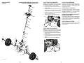
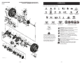
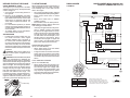
Owner's Manual
30" RIDING MOWER
SIDE DISCHARGE
ELECTRIC START
www.mcculloch.biz
Catalog No.
MC30
IMPORTANT:
Read and follow all Safety
Rules and Instructions before
op er at ing this equipment.
Patents Pending
Gasoline containing up to 10% ethanol (E10) is acceptable for use in this machine.
The use of any gasoline exceeding 10% ethanol (E10) will void the product warranty.
06.28.11 TH/BD
www.mcculloch.biz
Printed in the U.S.A.
532 44 18-76 Rev. 6
TABLE OF CONTENTS
Warranty ................................................. 2
Safety Rules ........................................... 3
Product Specifications ............................ 6
Assembly/Pre-Operation ........................ 7
Operation .............................................. 11
Maintenance Schedule ......................... 18
SERVICE NOTES
Maintenance ......................................... 18
Service and Adjustments ...................... 22
Storage ................................................. 26
Troubleshooting .................................... 27
Repair Parts.......................................... 29
WARRANTY
LIMITED WARRANTY
The Manufacturer warrants to the original consumer purchaser that this product as manufactured is free from defects in materials and workmanship. For a period of two (2) years from date of purchase by the original consumer purchaser, we will repair
or replace, at our option, without charge for parts or labor incurred in replacing parts, any part which we find to be defective
due to materials or workmanship. This Warranty is subject to the following limitations and exclusions.
1.
This warranty does not apply to the engine, battery (except as noted below) or components parts thereof. Please refer to
the applicable manufacturer's warranty on these items.
2.
Transportation charges for the movement of any power equipment unit or attachment are the responsibility of the purchaser. Transportation charges for any parts submitted for replacement under this warranty must be paid by the purchaser
unless such return is requested by the manufacturer.
3.
Battery Warranty: On products equipped with a Battery, we will replace, without charge to you, any battery which we find
to be defective in manufacture, during the first ninety (90) days of ownership. After ninety (90) days, we will exchange the
Battery, charging you 1/12 of the price of a new Battery for each full month from the date of the original sale. Battery must
be maintained in accordance with the instructions furnished.
4.
The Warranty does not apply to any products used for rental or commercial purposes.
5.
This Warranty applies only to products which have been properly assembled, adjusted, operated, and maintained in accordance with the instructions furnished. This Warranty does not apply to any product which has been subjected to alteration, misuse, abuse, improper assembly or installation, delivery damage, or to normal wear of the product.
6.
Exclusions: Excluded from this Warranty are belts, blades, blade adapters, normal wear, normal adjustments, standard
hardware and normal maintenance.
7.
In the event you have a claim under this Warranty, you must return the product to an authorized service dealer.
Should you have any unanswered questions concerning this Warranty, please contact:
In Canada contact:
HOP
Outdoor Products Customer Service Dept.
9335 Harris Corners Parkway
Charlotte, NC 28269 USA
HOP
5855 Terry Fox Way
Mississauga, Ontario
L5V 3E4
giving the model number, serial number and date of purchase of your product and the name and address of the authorized
dealer from whom it was purchased.
THIS WARRANTY DOES NOT APPLY TO INCIDENTAL OR CONSEQUENTIAL DAMAGES AND ANY IMPLIED WARRANTIES ARE LIMITED TO THE SAME TIME PERIODS STATED HEREIN FOR OUR EXPRESSED WARRANTIES. Some areas
do not allow the limitation of consequential damages or limitations of how long an implied Warranty may last, so the above
limitations or exclusions may not apply to you. This Warranty gives you specific legal rights, and you may have other rights
which vary from locale to locale.
This is a limited Warranty within the meaning of that term as defined in the Magnuson-Moss Act of 1975.
2
43
SERVICE NOTES
SAFETY RULES
DANGER: This cutting machine is capable of amputating hands and feet and throwing
objects. Failure to observe the following safety instructions could result in serious injury
or death.
• Never direct discharged material toward
anyone. Avoid discharging material
against a wall or obstruction. Material may
ricochet back toward the operator. Stop
the blade when crossing gravel surfaces.
• Do not operate machine without the entire
grass catcher, discharge chute, or other
safety devices in place and working.
• Slow down before turning.
• Never leave a running machine unattended. Always turn off blade, set parking brake, stop engine, and remove keys
before dismounting.
• Disengage blade when not mowing. Shut
off engine and wait for all parts to come
to a complete stop before cleaning the
machine, removing the grass catcher, or
unclogging the discharge chute.
• Operate machine only in daylight or good
artificial light.
• Do not operate the machine while under
the influence of alcohol or drugs.
• Watch for traffic when operating near or
crossing roadways.
• Use extra care when loading or unloading
the machine into a trailer or truck.
• Always wear eye protection when operating machine.
• Data indicates that operators, age 60
years and above, are involved in a large
percentage of riding mower-related injuries. These operators should evaluate
their ability to operate the riding mower
safely enough to protect themselves and
others from serious injury.
• Keep machine free of grass , leaves or
other debris build-up which can touch hot
exhaust / engine parts and burn. Do not
allow the mower deck to plow leaves or
other debris which can cause build-up to
occur. Clean any oil or fuel spillage before
operating or storing the machine. Allow
machine to cool before storage.
WARNING: In order to prevent accidental starting when setting up, transporting,
adjusting or making repairs, always disconnect spark plug wire and place wire where
it cannot contact spark plug.
WARNING: Do not coast down a hill
in neutral, you may lose control of the riding mower.
WARNING: Engine exhaust, some of its
constituents, and certain vehicle components
contain or emit chemicals known to the State
of California to cause cancer and birth defects
or other reproductive harm.
WARNING:This unit is not intended
for the use of wheel weights. Only use
attachments designed specifically for this
riding mower.
WARNING: Battery posts, terminals
and related accessories contain lead and
lead compounds, chemicals known to the
State of California to cause cancer and birth
defects or other reproductive harm. Wash
hands after handling.
I. GENERAL OPERATION
• Read, understand, and follow all instructions on the machine and in the manual
before starting.
• Do not put hands or feet near rotating parts
or under the machine. Keep clear of the
discharge opening at all times.
• Only allow responsible adults, who are
familiar with the instructions, to operate
the machine.
• Clear the area of objects such as rocks,
toys, wire, etc., which could be picked up
and thrown by the blade.
• Be sure the area is clear of bystanders
before operating. Stop machine if anyone
enters the area.
• Never carry passengers.
• Do not mow in reverse unless absolutely
necessary. Always look down and behind
before and while backing.
42
3
SAFETY RULES
III. CHILDREN
41
FOL
D AL
ONG
TH
D
I
S
O
IS A
TTED
15 D
LINE
E
G
REE
SLO
PE
4
ONLY RIDE UP AND DOWN HILL,
NOT ACROSS HILL
SAFE HANDLING OF GASOLINE
To avoid personal injury or property damage, use extreme care in handling gasoline.
Gasoline is extremely flammable and the
vapors are explosive.
• Extinguish all cigarettes, cigars, pipes,
and other sources of ignition.
• Use only approved gasoline container.
• Never remove gas cap or add fuel with
the engine running. Allow engine to cool
before refueling.
• Never fuel the machine indoors.
• Never store the machine or fuel container
where there is an open flame, spark, or
pilot light such as on a water heater or
other appliances.
15 DEGREES MAX.
IV. SERVICE
WARNING: To avoid serious injury, operate your tractor up and
down the face of slopes, never across the face. Do not mow
slopes greater than 15 degrees. Make turns gradually to prevent
tipping or loss of control. Exercise extreme caution when
changing direction on slopes.
Tragic accidents can occur if the operator is
not alert to the presence of children. Children
are often attracted to the machine and the
mowing activity. Never assume that children
will remain where you last saw them.
• Keep children out of the mowing area and
in the watchful care of a responsible adult
other than the operator.
• Be alert and turn machine off if a child
enters the area.
• Before and while backing, look behind and
down for small children.
• Never carry children, even with the blade
shut off. They may fall off and be seriously
injured or interfere with safe machine
operation. Children who have been given
rides in the past may suddenly appear in
the mowing area for another ride and be
run over or backed over by the machine.
• Never allow children to operate the machine.
• Use extra care when approaching blind
corners, shrubs, trees, or other objects
that may block your view of a child.
1. Fold this page along dotted line indicated above.
2. Hold page before you so that its left edge is vertically parallel to a tree
trunk or other upright structure.
3. Sight across the fold in the direction of hill slope you want to measure.
4. Compare the angle of the fold with the slope of the hill.
Slopes are a major factor related to loss of
control and tip-over accidents, which can
result in severe injury or death. Operation
on all slopes requires extra caution. If you
cannot back up the slope or if you feel uneasy
on it, do not mow it.
• Mow up and down slopes (15° Max), not
across.
• Watch for holes, ruts, bumps, rocks, or
other hidden objects. Uneven terrain could
overturn the machine. Tall grass can hide
obstacles.
• Choose a low ground speed so that you
will not have to stop or shift while on the
slope.
• Do not mow on wet grass. Tires may lose
traction.
• Always keep the machine in gear when
going down slopes. Do not shift to neutral
and coast downhill.
• If machine stops while going uphill,
disengage blade, shift into reverse and
back down slowly.
• Avoid starting, stopping, or turning on a
slope. If the tires lose traction, disengage
the blade and proceed slowly straight down
the slope.
• Keep all movement on the slopes slow and
gradual. Do not make sudden changes
in speed or direction, which could cause
the machine to roll over.
• Use extra care while operating machine
with grass catchers or other attachments;
they can affect the stability of the machine.
• Do no use on steep slopes.
• Do not try to stabilize the machine by
putting your foot on the ground.
• Do not mow near drop-offs, ditches, or
embankments. The machine could suddenly roll over if a wheel is over the edge
or if the edge caves in.
SUGGESTED GUIDE FOR SIGHTING SLOPES FOR SAFE OPERATION
II. SLOPE OPERATION
RIDING MOWER
MODEL NUMBER MC30 (96022001300)
PRODUCT NUMBER 960 22 00-13
DECALS
1
5
2 3
6
4
KEY PART
NO. NO.
DESCRIPTION
1
2
3
4
5
6
---
DECAL, STEERING WHEEL
DECAL, V-BELT SCH 30"
DECAL, WARN. DEFLECT/CTFGR
DECAL, DECK
DECAL, ENGINE H.P.
LABEL, EPA
MANUAL OWNER'S ENGLISH
MANUAL OWNER'S SPANISH
532 43 79-66
532 44 14-97
532 42 51-12
532 44 14-15
532 40 88-07
532 43 81-60
532 44 18-76
532 44 18-77
NOTE: All component dimensions given in U.S. inches
1 inch = 25.4 mm
40
SAFETY RULES
• Never fill containers inside a vehicle or
on a truck or trailer bed with plastic liner.
Always place containers on the ground
away from your vehicle when filling.
• Remove gas-powered equipment from the
truck or trailer and refuel it on the ground.
If this is not possible, then refuel such
equipment with a portable container, rather
than from a gasoline dispenser nozzle.
• Keep the nozzle in contact with the rim
of the fuel tank or container opening at
all times until fueling is complete. Do not
use a nozzle lock-open device.
• If fuel is spilled on clothing, change clothing
immediately.
• Never overfill fuel tank. Replace gas cap
and tighten securely.
GENERAL SERVICE
• Never operate machine in a closed area.
• Keep all nuts and bolts tight to be sure the
equipment is in safe working condition.
• Never tamper with safety devices. Check
their proper operation regularly.
• Keep machine free of grass, leaves, or
other debris build-up. Clean oil or fuel spillage and remove any fuel-soaked debris.
Allow machine to cool before storing.
• If you strike a foreign object, stop and
inspect the machine. Repair, if necessary,
before restarting.
• Never make any adjustments or repairs
with the engine running.
• Check grass catcher components and the
discharge chute frequently and replace
with manufacturer’s rec ommended parts,
when necessary.
• Mower blade is sharp. Wrap the blade or
wear gloves, and use extra caution when
servicing them.
• Check brake operation frequently. Adjust
and service as required.
• Maintain or replace safety and instruction
labels, as necessary.
• Be sure the area is clear of bystanders
before operating. Stop machine if anyone
enters the area.
• Never carry passengers.
• Do not mow in reverse unless absolutely
necessary. Always look down and behind
before and while backing.
5
PRODUCT SPECIFICATIONS
1.5 Gallons
Unleaded Regular
Oil Type
(API SG-SL):
SAE 30 (Above 32°F)
SAE 5W30 (Below 32°F)
Oil Capacity:
48 Oz.
Spark Plug:
Champion RC12YC
(Gap: .030")
Ground Speed
(Mph):
Forward:
Reverse:
Charging System:
3 Amps @ Battery
Blade Bolt Torque:
45-55 Ft. Lbs.
MODEL NUMBER MC30 (96022001300)
PRODUCT NUMBER 960 22 00-13
MOWER DECK
CUSTOMER RESPONSIBILITIES
PRODUCT SPECIFICATIONS
Gasoline Capacity
and Type:
RIDING MOWER
• Read and observe the safety rules.
• Follow a regular schedule in maintaining, caring for and using your tractor.
• Follow the instructions under “Customer
Responsibilities” and “Storage” sections
of this owner’s manual.
WARNING: This riding mower is
equipped with an internal combustion engine and should not be used on or near any
unimproved forest-covered, brush-covered
or grass-covered land unless the engine’s
exhaust system is equipped with a spark
arrester meeting applicable local or state
laws (if any). If a spark arrester is used, it
should be maintained in effective working
order by the operator.
A spark arrester for the muffler is available
through your nearest authorized service
center/department.
In the state of California the above is required
by law (Section 4442 of the California Public
Resources Code). Other states may have
similar laws. Federal laws apply on federal
lands.
0-4
0-2
CONGRATULATIONS on your purchase of
a new riding mower. It has been designed,
engineered and manufactured to give you
the best possible dependability and performance.
Should you experience any problem you
cannot easily remedy, please contact a
qualified service center. We have competent,
well-trained representatives and the proper
tools to service or repair this riding mower.
Please read and retain this manual. The
instructions will enable you to assemble and
maintain your riding mower properly. Always
observe the “SAFETY RULES”.
UNASSEMBLED PARTS
KEY PART
NO. NO.
DESCRIPTION
1
2
3
4
5
6
7
10
12
13
14
17
18
19
20
22
25
26
27
28
29
30
31
32
34
35
36
37
40
48
49
50
52
53
55
56
57
59
61
62
63
64
DECK
MANDREL ASM
KEEPER, BELT
PULLEY, MANDREL
BELT
COVER, MANDREL
LIFT ASM, DECK
DEFLECTOR
PIN, HINGE
SPRING, TORSION
ARM, MOWER SUPPORT
WASHER
PIN
BOLT, SHOULDER
PIN COTTER 5/16 BOW TIE LOCK
LINK ASM DECK
RETAINER SPRING 1"
SPACER, MANDREL
BOLT, MANDREL
NUT FLANGE LOCK TOP
BLADE
BOLT, BLADE
PULLEY, IDLER
GUARD, IDLER TUV
BOLT, 3/8-16 X 1 1/2
ARM, BRAKE
SCREW THD ROLL 1/4-20 X 5/8
NUT, 3/8-16 FLANGE
WASHER, 16 GA.
ARM CLUTCHING
SPACER RETAINER
SCREW 3/8-16 X 1
SCREW 1/4-20 X 3/8
SPRING RETURN DECK
E-RING 5/16
ROD ANTI-SWAY
WASHER 13/32 X 13/16 X 12 GA
GUARD TUV IDLER
MULCH COVER ASM
TRUNION SUSPENSION ARM
NUT LIFT LINK 7/16-20
SCREW THDROL 3/8-16 X 1/2
532 43 68-48
532 19 28-70
532 43 68-56
532 43 68-55
532 44 15-97
532 43 68-63
532 43 86-91
532 43 96-38
532 43 66-47
532 43 74-62
532 19 51-85
819 19 19-12
532 19 42-09
532 19 65-39
532 19 42-08
532 44 15-98
532 12 47-88
532 18 76-90
532 17 39-84
532 40 02-34
532 41 92-73
532 19 30-03
532 19 31-97
532 14 10-43
872 11 06-12
532 19 94-70
532 13 77-29
873 90 06-00
819 17 16-16
532 43 68-57
532 19 90-92
817 00 06-16
817 60 04-06
532 40 18-72
532 43 79-88
532 43 68-62
819 13 13-12
532 43 68-58
532 43 79-47
532 17 62-05
532 17 59-94
817 67 06-08
NOTE: All component dimensions given in U.S. inches
1 inch = 25.4 mm
6
39
RIDING MOWER
MODEL NUMBER MC30 (96022001300)
PRODUCT NUMBER 960 22 00-13
MOWER DECK
36
Your new riding mower has been assembled at the factory with the exception of those parts
left unassembled for shipping purposes. To ensure safe and proper operation of your riding
mower all parts and hardware you assemble must be tightened securely. Use the correct
tools as necessary to ensure proper tightness.
6
19
7
TOOLS REQUIRED FOR ASSEMBLY
TO INSTALL STEERING WHEEL
1. Slide extension shaft onto steering shaft.
2. Slide steering shaft protective foam cover
over steering shaft.
3. Place steering boot over steering shaft
and push down to secure.
4. Position front wheels of the riding mower
so they are pointing straight forward.
5. Remove steering wheel adapter from
steering wheel and slide adapter onto
steering shaft.
7. Press steering wheel into position on
shaft, install large washer, lock washer,
bolt and tighten securely.
8. Snap steering wheel insert into center of
steering wheel securely.
A socket wrench set will make assembly
easier. Standard wrench sizes you need
are listed below.
10
(1) 1/2" wrench
(1) Utility knife
(1) Tire pressure gauge
40
When right or left hand is mentioned in
this manual, it means when you are in the
operating position (seated behind the steering wheel).
40
19
5
61
13
TO REMOVE RIDING MOWER FROM
CARTON
28
4
55
12
56
50
37
49
59
27
32
27
20
37
31
26
3
1
34
57
48
35 52
34
19
53
64
37
63 62
19
14
20
57
22
UNPACK CARTON
1. Remove all accessible loose parts and
parts boxes from carton.
2. Cut along dotted lines on all four panels
of carton. Remove end panels and lay
side panels flat.
3. Remove packing materials from riding
mower.
4. Check for any additional loose parts or
cartons and remove.
NOTE: Only cut carton with a short blade
utility knife, a long blade or saw can puncture
tires on unit.
Lock Washer
Washer
63
Adapter
Extension
Shaft
CHECK BATTERY
Ensure battery is securely fastened, and that
all wires are securely connected.
• Battery is located under the seat.
• Battery has been fully charged from the
factory, before installation.
LRV-B_Deck_4_r1
Seat
Battery
30
38
Foam Cover
Steering Shaft
18
29
Insert
Steering Boot
2
17
Bolt
Steering Wheel
HOW TO SET UP YOUR RIDING
MOWER
25
18
17
ASSEMBLY/PRE-OPERATION
7
RIDING MOWER
INSTALL SEAT
1. Remove bolt and flat washer securing
seat to cardboard packing and set aside
for assembly of seat to riding mower.
Remove the cardboard packing and
discard.
2. Place seat on seat pan so all three (3)
bottom pads are positioned over large
slotted holes in pan.
3. Push down on seat to engage pads in
slots and pull seat towards rear of riding
mower.
4. Raise seat and tighten bolt and large flat
washer securely.
5. Remove tape and discard.
6. Lower seat into operating position and
sit on seat. Press clutch/brake pedal all
the way down. If operating position is not
comfortable, adjust seat.
Lumbar
Adjustment Knob
Pad
NOTE: You may now roll your riding
mower off the skid. Follow the appropriate
instruction below to remove the riding mower
from the skid.
Flat
washer
Seat
pan
Bolt
Adjustment Lever
LUMBAR SUPPORT • Loosen lumbar adjustment knob.
• Slide seat back up or down to most comfortable position for lower back support.
• Tighten lumbar adjustment knob.
Tape
Slot
Tab
MODEL NUMBER MC30 (96022001300)
PRODUCT NUMBER 960 22 00-13
STEERING
WARNING: Before starting, read, understand and follow all instructions in the
Operation section of this manual. Be sure
riding mower is in a well-ventilated area.
Be sure the area in front of riding mower is
clear of other people and objects.
Adjustment
handle
TO ADJUST SEAT
TO ROLL RIDING MOWER OFF
SKID (See Operation section for
location and function of controls)
FRONT AND BACK • Sit in seat.
• Lift up adjustment lever and slide seat
until a comfortable position is reached
which allows you to press clutch/brake
pedal all the way down.
• Release lever to lock seat in position.
1. Raise deck lift lever to its highest position.
2. Release parking brake by depressing
clutch/brake pedal.
3. Shift unit to neutral.
4. Roll riding mower forward off skid.
8
KEY PART
NO. NO.
DESCRIPTION
1
2
3
4
5
6
7
9
10
11
12
13
14
16
15
17
19
20
23
26
27
28
29
30
31
32
34
35
36
37
38
39
41
42
43
44
WHEEL TUBE
E-CLIP
WASHER, HARDENED
WASHER, 1/4 X 3/4
SPINDLE, RH
WASHER, HARDENED THRUST
BUSHING, STEERING COLUMN
WASHER
WELDMENT, LWR STRG SHAFT
LINK, STRNG LH
LINK, STRNG RH
BOLT, 5/16-18 X 1 1/2
WASHER 11/32 X 3/4 X 16 GA
BUSHING SNAP
NUT, 5/16-18
SUPPORT, UPPER STEERING
BOLT, 5/16-18 X 3/4
CLIP, RETAINER SPRING
ADAPTER, STEERING WHEEL
WHEEL, STEERING
CAP, STEERING WHEEL
CLIP, RETAINER SPRING
SPINDLE LH
CAP, HUB, AXLE
WASHER 1-1/16 X 2 X 10GA.
SCREW HEXWSH THD 5/16-18 X 1-3/4
SHAFT STEERING UPPER
BOOT LOWER STEERING WHEEL
SHAFT EXTENSION STEERING SPLINE
BOLT FIN HEX 5/16-18 UNC X 5 GR5
WASHER LOCK HVY HLCL SPR 5/16
WASHER
FOAM SHAFT STEERING
PIN, 5/64 X 3/4 COTTER
CROWNLOCK NUT 5/16-24 UNF
BUSHING
532 44 20-64
812 00 00-01
532 18 89-67
532 12 17-49
532 43 61-81
532 12 49-31
532 12 49-37
819 13 14-14
532 42 80-57
532 43 61-83
532 43 61-84
874 78 05-24
819 11 12-16
532 43 62-82
873 80 05-00
532 43 61-78
817 00 05-12
532 42 80-45
532 43 77-47
532 42 45-51
532 44 15-06
532 19 98-49
532 43 61-80
532 19 32-68
819 34 32-10
817 58 05-20
532 43 61-82
532 44 20-66
532 19 60-75
874 78 05-80
810 04 05-00
819 11 38-12
532 43 65-90
532 42 10-76
873 54 05-00
532 42 80-44
NOTE: All component dimensions given in U.S. inches
1 inch = 25.4 mm
37
RIDING MOWER
MODEL NUMBER MC30 (96022001300)
PRODUCT NUMBER 960 22 00-13
STEERING
27
37
38
39
CHECK TIRE PRESSURE
TO ATTACH FRONT BUMPER
NOTE: For ease of assembly, you may wish
to obtain the assistance of another person
for mounting bumper to riding mower.
1. Remove (2) screws from front chassis of
riding mower.
2. Tilt the front bumper so that the bumper
tabs catch the slots on the front of the
chassis and lower the bumper in to place.
3. Attach the bumper to front of chassis with
screws removed in step 1.
4. Tighten the two (2) screws securely.
The tires on your riding mower were overinflated at the factory for shipping purposes.
Correct tire pressure is important for best
cutting performance.
CHECK DECK LEVELNESS
For best cutting results, mower housing
should be properly leveled. See “TO LEVEL
MOWER HOUSING” in the Service and
Adjustments section of this manual.
CHECK FOR PROPER POSITON OF
MOWER DRIVE BELT
See the figure that is shown for replacing the
mower drive belt in the service and adjustment section of this manual. Verify that the
belt is routed correctly.
Tab
26
23
CHECK BRAKE SYSTEM
36
After you learn how to operate your riding
mower, check to see that the brake is operating properly.
Slot
34
Screw
TO ATTACH REAR BUMPER
28
NOTE: For ease of assembly, you may wish
to obtain the assistance of another person
for mounting bumper to riding mower.
1. Remove (4) screws from rear chassis of
riding mower.
2. Position bumper as shown and assemble
to rear chassis with screws removed in
step 1.
3. Tighten the four (4) screws securely.
35
30
1
2
3
Front Bumper
41
6
7
2
7
6
4
16
19
5
17
32
12
15
9 13
38
14
2
6
7
19
7
6
29
32
11
43
20
31
10
44
42
14
38
1
Rear Bumper
Screw
4
43
3
30
2
LRV-B_Steering_3
36
9
✓CHECKLIST
RIDING MOWER
DRIVE
MODEL NUMBER MC30 (96022001300)
PRODUCT NUMBER 960 22 00-13
Before you operate your new riding mower,
we wish to assure that you receive the best
performance and satisfaction from this Quality Product.
KEY PART
NO. NO.
Please review the following checklist:
✓ All assembly instructions have been
completed.
✓ No remaining loose parts in carton.
✓ Battery is properly connected.
✓ Seat is adjusted comfortably and tightened securely.
✓ All tires are properly inflated. (For shipping purposes, the tires were overinflated
at the factory).
✓ Be sure mower deck is properly leveled
side-to-side/front-to-rear for best cutting
results. (Tires must be properly inflated
for leveling).
✓ Check mower belt. Be sure it is routed
properly around pulleys and inside all belt
keepers.
✓ Check wiring. See that all connections
are still secure and wires are properly
clamped.
While learning how to use your riding mower,
pay extra attention to the following important
items:
✓ Engine oil is at proper level.
✓ Fuel tank is filled with fresh, clean, regular
unleaded gasoline.
✓ Become familiar with all controls, their
location and function. Operate them
before you start the engine.
✓ Be sure brake system is in safe operating
condition.
✓ Be sure Operator Presence System and
Reverse Operation System (ROS) are
working properly (See the Operation and
Maintenance sections in this manual).
10
1
2
3
6
7
8
9
10
11
12
13
14
15
16
17
18
19
532 44 20-79
532 12 17-48
812 00 00-01
532 15 69-72
874 78 04-28
532 43 66-95
532 44 19-36
817 00 05-12
532 43 67-41
532 43 61-48
532 43 72-80
532 43 71-76
532 44 25-51
532 43 61-53
532 43 72-82
532 43 61-49
818 05 10-10
20
22
23
32
33
34
36
37
39
40
41
532 12 49-31
532 43 66-96
818 10 10-08
532 43 61-51
532 43 61-50
877 10 10-40
532 43 57-22
532 43 61-52
532 43 04-70
532 43 69-39
532 10 95-53
43
873 80 05-00
44
45
47
532 43 66-52
532 43 61-54
532 43 69-49
48
817 54 10-16
51
53
54
55
57
59
60
62
63
65
66
67
68
69
532 43 67-39
873 90 06-00
532 43 57-26
532 43 77-77
532 43 65-59
532 44 10-97
532 43 77-87
532 43 77-86
532 43 77-85
532 43 57-23
532 43 57-24
532 43 57-25
532 43 57-28
532 43 57-27
KEY PART
NO. NO.
DESCRIPTION
WHEEL ASM (REAR)
WASHER, 16 GA.
E-CLIP
SPACER AXLE
HCS 1/4-20 X 1-3/4 GR 5 ZD
WELMENT SUPPORT AXLE RH
SUBASM FINAL DRIVE
SCREW 5/16 - 18 X 3/4
BRACKET.SUPPORT.RH
CASE CHAIN RH
BEARING BALL 6207-SRS
SPROCKET DRIVEN 37 TOOTH
TUBE INPUT HEX
CHAIN PRIMARY DRIVE
BEARING BALL 6204-3-2RS
CASE CHAIN LH
SCREW 10 - 24 X 5/8 PAN HEAD
TORX
WASHER THRUST .75 X 1.230
WELMENT SUPPORT AXLE LH
SCREW TORX #10 - 14 X 1/2
BLOCK TENSION CHAIN
SPRING ADJUSTER TENSION
PIN CLEVIS 5/16 X 2-1/2
SHAFT INPUT CLUTCH
SPROCKETSPLINED14TOOTH
BEARING BALL
ARM BRAKE
SWITCH INTLK CL MWR GRY
4 TERM
NUT LOCK HEX W/INSERT
5/16 - 18 UNC
COVER END HEX
SPRING DRIVE
BRACKET MOUNT CABLE
LRV B
SCREW.HEX.HEAD WASH.1024X1.00
BRACKET SUPPORT LH
LOCK NUT, FLANGED
BEARING BALL
COVER WHEEL CLUTCH
WHEEL FRICTION
PLATE.CLUTCH.DRIVE
PLATE PRESSURE DRIVE
PLATE CLUTCH BRAKE
PLATE PRESSURE BRAKE
PLATE PRESSURE MASTER
BEARING THRUST 20MM
PLATE THROWOUT
BEARING BALL LOOSE
COVER CLUTCH
70
71
72
73
75
76
78
532 41 15-55
532 43 68-65
872 11 04-06
873 68 04-00
532 43 67-00
532 18 35-00
532 42 90-55
79
80
874 78 04-12
810 04 04-00
81
84
85
86
87
88
89
90
91
94
95
96
97
98
819 09 12-10
819 11 16-10
532 43 69-14
532 43 73-04
532 43 69-48
532 43 67-01
532 43 72-99
819 11 14-16
532 43 69-24
532 43 69-18
532 43 68-66
532 43 77-67
532 43 69-25
532 15 03-60
101
817 06 06-24
102
103
104
105
106
107
532 08 67-77
532 10 44-45
532 43 77-81
532 43 61-42
532 19 43-21
532 12 47-88
108
109
110
111
112
113
114
532 43 67-84
532 19 32-68
532 42 84-61
532 12 35-83
818 10 10-12
873 90 05-00
532 43 62-82
DESCRIPTION
GRIP LEVER
TUBE SHIFT LRV
BOLT CARR.
NUT CROWNLOCK 1/4 - 20 UNC
BRACKET MOUNT SHIFT
HUB SHIFT
SPACER NYLON .866 X 1.25 X
.250
BOLT.FIN.HEX.1/4-20 UNC X .75
WASHER LOCK HVY HLCL
SPRING
WASHER 9/32 X 3/4 X 10 GA.
WASHER 11/32 X 1.00 X 10 GA.
SPRING FRICTION PACK
BUSHING PACK FRICTION FD2
WASHER PLASTIC
STUD PACK FRICTION
SPACER PACK FRICTION FD2
WASHER.11/32 X 7/8 X 16 GA.
SUBASM.LINK.SHIFT
WELDMENT.SHIFT.FD2
PLATE.SHIFT
DRUM CLUTCH MULTI DISC
SUBASM LINK SHIFT PRIMARY
NUT LOCK CENTER 1/4 - 28
FNTHD
SCREW.3/8-16X1-1/2. SMGML.
TAP/R
THREAD.CUTTER
SWITCH.SEAT.
HUB CENTER
SPRING WAVE C125-H5
SPACER RETAINER
RETAINER.SPRING.1”.ZINC/
CAD
BUSHING.5/16IDX7/16ODX1/2
CAP.HUB.AXLE.1.50 X 1.00
BRACKET SHIFTER FLEX
KEY.SQUARE.2.0 X .1845/.1865
SCREW TORX #10-14 X .750
NUT LOCK FLANGE HEX
BEARING FLANGE
NOTE: All component dimensions given in U.S. inches
1 inch = 25.4 mm
35
RIDING MOWER
MODEL NUMBER MC30 (96022001300)
PRODUCT NUMBER 960 22 00-13
DRIVE
109
These symbols may appear on your riding mower or in literature supplied with the product.
Learn and understand their meaning.
1
3 2
101 102
REVERSE
103
106
70
2
6
110
2
7
98
81
FUEL
72
84
85
86
78
88
54
ATTACHMENT
CLUTCH ENGAGED
13
Failure to follow instructions
could result in serious injury or
death. The safety alert symbol
is used to identify safety information about hazards which can
result in death, serious injury
and/or property damage.
18
19
19
20 17
44
22
54
40
19
19 112
19 112
48
41
112
43
47
57
96 23
23
59 60
59
REVERSE
FORWARD
DANGER, KEEP HANDS
AND FEET AWAY
23
51
105
MOWER HEIGHT
MOWER LIFT
15
SLOPE HAZARDS
KEEP AREA CLEAR
(SEE SAFETY RULES SECTION)
2
1
6 2
CAUTION when used without the alert symbol,
indicates a situation that could result in damage
to the tractor and/or engine.
HOT SURFACES indicates a hazard which,
if not avoided, could result in death, serious injury
and/or property damage.
FIRE indicates a hazard which, if not avoided,
could result in death, serious injury and/or
property damage.
10
62
65
104
PARKING BRAKE
UNLOCKED
WARNING indicates a hazard which, if not avoided,
could result in death or serious injury.
62
63
LRV-B_Drive_1_r3
23
114
48
45
23
PARKING BRAKE
LOCKED
CAUTION indicates a hazard which, if not avoided,
might result in minor or moderate injury.
36
39
ATTACHMENT
CLUTCH DISENGAGED
16
19
55
BATTERY
BRAKE/CLUTCH
PEDAL
37 54
PARKING BRAKE
DANGER indicates a hazard which, if not avoided,
will result in death or serious injury.
33
39
OIL PRESSURE
113
15
32
ENGINE START
ENGINE ON
98
94
107
34
54
SLOW
111
80
13 14
53
FAST
15
91
87
12
REVERSE
OPERATION
SYSTEM (ROS)
80
76
89
90
CHOKE
8
111
9
73 75
79
ENGINE OFF
11
72
90
LOW
P
98
97 80
95
7
10
10
108
HIGH
IGNITION SWITCH
114
10
73
43
NEUTRAL
98
71
80
OPERATION
66 67
68
2
3
69
109
68
34
11
KNOW YOUR RIDING MOWER
RIDING MOWER
READ THIS OWNER'S MANUAL AND SAFETY RULES BEFORE OPERATING
YOUR RIDING MOWER
Compare the illustrations with your riding mower to familiarize yourself with the locations
of various controls and adjustments. Save this manual for future reference.
CHASSIS
KEY PART
NO. NO.
Brake Pedal
Parking
Brake Lever
ROS
"ON"
Deck Clutch
Lever
Ignition
Switch
Lift Lever
Plunger
Throttle/
Choke
Control
Height
Adjustment
Lever
Motion
Control
Lever
Our riding mowers conform to the applicable safety standards of the
American National Standards Institute.
DECK CLUTCH LEVER - Used to engage
the mower blade.
PARKING BRAKE LEVER - Locks parking
brake into brake position.
BRAKE PEDAL - Used for braking the riding
mower and starting the engine.
MOTION CONTROL LEVER - Selects the
speed and direction of the riding mower.
HEIGHT ADJUSTMENT LEVER - Used to
adjust mower cutting height.
ROS “ON” POSITION - Allows operation of
mower deck or other powered attachment
while in reverse.
IGNITION SWITCH - Used for starting and
stopping the engine.
1
2
7
8
10
11
13
14
15
16
18
532 43 61-76
532 18 01-66
532 43 61-77
532 43 96-14
532 44 18-05
532 19 93-70
532 44 20-71
532 44 20-75
532 44 20-69
532 43 93-95
– – – – – –
19
22
23
24
532 43 68-61
532 44 17-15
532 14 98-46
532 41 63-58
25
26
29
32
33
34
35
39
40
41
42
43
44
45
51
52
53
54
55
56
57
59
60
62
63
64
65
66
67
872 14 04-24
873 51 04-00
532 43 89-21
817 06 06-20
532 12 41-81
532 12 37-40
872 05 04-12
532 13 43-00
532 12 12-48
532 12 39-76
532 17 18-52
873 80 05-00
532 43 66-12
817 00 05-12
532 42 88-56
532 14 50-06
532 43 85-62
532 43 64-73
532 43 58-08
532 44 19-25
532 43 64-79
819 18 24-11
532 43 78-56
532 40 04-14
532 41 41-19
532 12 34-87
532 43 02-19
532 43 66-06
532 42 17-56
MODEL NUMBER MC30 (96022001300)
PRODUCT NUMBER 960 22 00-13
KEY PART
NO. NO.
DESCRIPTION
WELDMENT, CHASSIS
BRACKET, SEAT
PLATE, ENGINE
BRACKET, CHASSIS FRONT
PAN, SEAT
BRACKET, SWITCH MOUNTING
COVER, FOOT REST
FOOTREST STRUCTURAL
SUPPORT, FOOT REST
PANEL ASM, CONTROL
ENGINE, 217807-1537-G1
(439614) (NON-CALIFORNIA)
(ORDER PARTS FROM
ENGINE MANUFACTURER)
KEEPER, BELT
DECK CLUTCH ASM
KNOB
SCREW #10 X 0.750 BOS
THREAD
BOLT
NUT 1/4-20
BOLT, 7/16-20 X 1.00
SCREW 3/8-16 X 1-1/4
SPRING, SEAT
SPRING
BOLT, 1/4-20 X 1 1/2
SPACER
BUSHING, NYLON SNAP
NUT, LOCK
BOLT, 5/16-18 SHOULDER
NUT, 5/16-18
SEAT
BOLT, 5/16-18 X 3/4
BRACKET
CLIP PUSH-IN HINGED
SCREW
DISC FRICTION
TORSION BODY UPPER
TORSION BODY LOWER
SPRING HELIX
WASHER 9/16ID X 1/2 20D11G
FUEL TANK ASM
FUEL LINE
PURGE LINE
CLAMP HOSE
FUEL CAP
FUEL TANK SUPPORT BRKT
SCREW #10 X 0.500
12
532 43 98-51
532 43 74-27
532 44 20-68
71
72
73
532 43 78-57
532 19 51-61
873 90 05-00
74
76
77
78
79
80
81
82
83
84
85
86
87
88
89
91
92
94
95
96
97
98
100
101
102
103
104
105
106
107
108
109
110
111
112
113
873 90 04-00
877 10 08-12
876 02 02-08
532 43 70-56
532 43 70-57
532 42 96-93
532 43 73-74
532 16 94-84
532 43 93-66
532 43 92-88
532 43 76-60
532 43 87-62
532 16 54-92
532 42 81-10
532 42 17-56
532 43 74-01
532 18 4471
874 49 05-48
532 43 67-02
532 44 20-73
532 43 64-72
817 49 04-08
532 19 76-61
532 19 82-00
874 76 06-12
819 13 38-12
818 10 10-08
532 44 20-78
532 43 68-34
532 44 20-74
532 43 71-68
532 43 90-08
532 42 21-45
532 43 81-71
817 72 04-08
817 06 05-12
DESCRIPTION
SHIELD HEAT
BRACKET MOUNT CABLE
CONSOLE CENTER
CUPHOLDER
THROTTLE ASM
STUD FASTNER
NUT LOCK HEX FLANGE 5/1618
NUT HEX FLANGE 1/4-20
PIN CLEVIS
PIN COTTER 1/16 X 1/2
BRACKET SUPPORT ROD
BRAKE WELDMENT
BRAKE PEDAL COVER
WELDMENTLINKCONNECTING
RETAINER CLIP
STEERING TOWER REAR
STEERING BOOT FRONT
PARKING BRAKE HANDLE
ACTUATOR PARKING BRAKE
SHOULDER BOLT
CROSS BRACE
SCREW
TRACK CLUTCH BRKT
BOLT
BOLT
BRACKET CLUTCHING
BUMPER REAR
PULLEY ENGINE
SCREW 1/4-20 X 1/2
HANDLE SLIDE SEAT
SPRING LATCH SEAT
BOLT FIN HEX 3/8-16 UNC X 3/4
WASHER 13/32 X 2 3/8 X 12 GA
SCREW TORK #10-14 X 1/2
ENGINE COVER
STRAP BATTERY
FRONT BRUSH GUARD
COVER REAR TRANSAXLE
BRAKE HANDLE PLATE
CONTROL PANEL HINGE PIN
SHIELD, BRAKE CABLE
SCREW THD CUT
SCREW 5/16-18 X 3/4
NOTE: All component dimensions given in U.S. inches
1 inch = 25.4 mm
THROTTLE/CHOKE CONTROL – Used for
starting and controlling engine speed.
LIFT LEVER PLUNGER - Used to release
height adjustment lever when changing its
position.
68
69
70
33
RIDING MOWER
MODEL NUMBER MC30 (96022001300)
PRODUCT NUMBER 960 22 00-13
CHASSIS
00155
100
35
44
103
102
11
40
110
45
26
110
53
65
53
34
41
45
42
16
45
40
39
2
97
55
57
60
106
52
67
43
56
42
59
29
52
63
71
Motion Control Lever
ENGINE • Move throttle control between half and full
speed (fast) position.
NOTE: Failure to move throttle control between half and full speed (fast) position, before stopping, may cause engine to “backfire”.
54
53
67
64
GROUND DRIVE • To stop ground drive, depress brake pedal
all the way down.
• Move motion control lever to neutral position.
TO SET PARKING BRAKE
Your riding mower is equipped with an operator presence sensing switch. When engine
is running, any attempt by the operator to
leave the seat without first setting the parking
brake will shut off the engine.
1. Depress brake pedal all the way down
and hold.
2. Pull parking brake lever up and hold,
release pressure from brake pedal, then
release parking brake lever. Pedal should
remain in brake position. Ensure parking
brake will hold mower secure.
105
10
39
34
41
HOW TO USE YOUR RIDING
MOWER
18
101
The operation of any riding mower can result in foreign objects thrown
into the eyes, which can result in severe eye damage. Always wear
safety glasses or eye shields while operating your riding mower or
performing any adjustments or repairs. We recommend a wide vision
safety mask over spectacles or standard safety glasses.
53
68
67
66
84
82
64
74
83
13
62
113
45
7
92
96
85
Throttle
45
69
86
112
33
70
32
109
67
45
112
111
113
32
45
14
108
1
51
23
MOWER BLADE • To stop mower blade, move deck clutch
lever to disengaged position.
22
45
107
24
98
72
8
25
19
45
45
88
67
104
94
24
87
72
73
• Turn ignition key to “STOP” position and
remove key. Always remove key when
leaving riding mower to prevent unauthorized use.
IMPORTANT: Leaving the ignition switch in
any position other than "STOP" will cause
the battery to discharge and go dead.
NOTE: Under certain conditions when riding
mower is standing idle with the engine running, hot engine exhaust gases may cause
“browning” of grass. To eliminate this possibility, always stop engine when stopping
riding mower on grass areas.
67
45
15
LRV-B_Chassis_8
STOPPING
91
81
82
78
45
45
45
79
77 76
73
32
95
80
(
) Deck Clutch
Control
“Engaged”
(
) Deck Clutch
CAUTION: Always stop riding mower
completely, as described above, before
leaving the operator's position.
Control
“Disengaged”
13
• The average lawn should be cut to approximately 2-1/2" during the cool season
and to over 3" during hot months. For
healthier and better looking lawns, mow
often and after moderate growth.
• For best cutting performance, grass over
6" in height should be mowed twice. Make
the first cut relatively high; the second to
desired height.
TO USE THROTTLE CONTROL
Always operate engine at full speed (fast).
• Operating engine at less than full speed
(fast) reduces engine's operating efficiency.
• Full speed (fast) offers the best mower
performance.
Throttle
TO OPERATE MOWER
Your riding mower is equipped with an
operator presence sensing switch. Any
attempt by the operator to leave the seat
with the engine running and the deck clutch
engaged will shut off the engine. You must
remain fully and centrally positioned in the
seat to prevent the engine from hesitating or
cutting off when operating your equipment
on rough, rolling terrain or hills.
1. Select desired height of cut.
2. Start mower blade by engaging deck
clutch lever.
TO STOP MOWER BLADE Disengage deck clutch lever.
TO MOVE FORWARD AND BACKWARD
The direction and speed of movement is
controlled by the motion control lever.
1. Ensure the parking brake is applied.
2. Start riding mower with motion control
lever in neutral (N) position.
3. Release parking brake.
4. Slowly move motion control lever to
desired position.
Deck Clutch Lever
"Disengaged" Position
Mower Height
Adjustment High
Position
Motion Control Lever
RIDING MOWER
MODEL NUMBER MC30 (96022001300)
PRODUCT NUMBER 960 22 00-13
ELECTRICAL
KEY PART
NO. NO.
DESCRIPTION
1
3
4
9
10
12
13
15
16
17
18
19
20
21
22
23
24
25
BATTERY
SWITCH, IGN, DLTA, P-IN, ROS
KEY/CHAIN
SWITCH, INTLK,CL, MWR, GRY
SWITCH, INTERLOCK, NONC,GRAY
SWITCH, SEAT, DP, ROS
HARNESS, IGN, ELECTSTART, LRV
SOLENOID
SCREW THD CUT 1/4-20 X 1/2 TY23
NUT KEPS HEX 1/4-20 UNC
CABLE BATTERY
CABLE STARTER
CABLE GROUND
SCREW 5/16-18 X 3/4
SCREW HEX M5X0.8.9MM
NUT M5
SCREW TORX #10-14 X .750
FUSE, 10
532 43 65-51
532 19 33-50
532 41 19-33
532 10 95-53
532 17 61-38
532 19 27-49
532 43 72-28
532 19 25-07
817 72 04-08
873 51 04-00
532 41 66-94
532 42 12-99
532 42 12-98
817 06 05-12
532 44 21-48
532 43 81-22
818 10 10-12
532 44 16-22
NOTE: All component dimensions given in U.S. inches
1 inch = 25.4 mm
Deck Clutch Lever
"Engaged" Position
TO ADJUST MOWER CUTTING HEIGHT
The position of the mower height deck lift
lever determines the cutting height.
• Grasp lift lever.
• Press lift lever plunger with thumb and
move lever to desired position.
The cutting height range is approximately
1-1/2 to 4". The heights are measured from
the ground to the blade tip with the engine
not running. These heights are approximate
and may vary depending upon soil conditions, height of grass and types of grass
being mowed.
Mower
Height Adjustment
Low Position
CAUTION: Do not operate the mower
without either the entire grass catcher, on
mowers so equipped, mulch cover, or the
deflector shield in place.
Deflector Shield
14
Mulch Cover
31
RIDING MOWER
MODEL NUMBER MC30 (96022001300)
PRODUCT NUMBER 960 22 00-13
ELECTRICAL
LRV2
25
3
4
1
12
ROS "ON" Position
21
22
Deflector
Shield
4. Rest the mulch cover on the deflector.
5. Attach the 2 bungees from the deflector
to the deck.
USING THE REVERSE OPERATION
SYSTEM Only use if you are certain no children or
other bystanders will enter the mowing
area.
1. Move motion control lever to neutral (N)
position.
2. With engine running, turn ignition key
counterclockwise to ROS "ON" position.
3. Look down and behind before and while
backing.
4. Slowly move motion control lever to
reverse (R) position to start movement.
5. When use of the ROS is no longer
needed, turn the ignition key clockwise
to engine "ON" position.
18
20
Hinge Bracket
WARNING: Backing up with the deck
clutch engaged while mowing is strongly
discouraged. Turning the ROS "ON", to allow reverse operation with the deck clutch
engaged, should only be done when the
operator decides it is necessary to reposition
the machine with the attachment engaged.
Do not mow in reverse unless absolutely
necessary.
13
10
REVERSE OPERATION SYSTEM (ROS)
Your riding mower is equipped with a Reverse
Operation System (ROS). Any attempt by
the operator to travel in the reverse direction with the deck clutch engaged will shut
off the engine unless ignition key is placed
in the ROS "ON" position.
Deflector Shield
TO OPERATE ON HILLS
WARNING: Do not drive up or down
hills with slopes greater than 15° and do not
drive across any slope. Use the slope guide
at the back of this manual.
• Choose the slowest speed before starting
up or down hills.
• Avoid stopping or changing speed on
hills.
• If stopping is absolutely necessary, push
clutch/brake pedal quickly to brake position and engage parking brake.
• Move motion control lever to neutral (N)
position.
• To restart movement, slowly release
parking brake and clutch/brake pedal.
• Make all turns slowly.
Engine "ON" Position
(Normal Operating)
23
19
9
17
16
24
15
TO ATTACH DEFLECTOR
1. Unhook the 2 bungees from deck to the
mulch cover.
TO TRANSPORT
When pushing or towing your riding mower,
be sure to disengage transmission by placing
shifter in neutral.
• Raise mower height adjustment to its highest position with mower height adjustment
lever.
• To reengage transmission, press brake
and shift out of neutral.
Bungee
Mulch Cover
Bungee
2. Lift the mulch cover.
3. Attach the deflector to the hinge bracket.
30
Mulch Cover
15
TO START ENGINE
When starting the engine for the first time or
if the engine has run out of fuel, it will take
extra cranking time to move fuel from the
tank to the engine.
• Sit on seat in operating position, depress
clutch/brake pedal and set parking brake.
• Place motion control lever in neutral
position.
• Move deck clutch lever to “DISENGAGED” position.
• Move throttle control to choke position.
NOTE: Before starting, read the warm and
cold starting procedures below.
• Insert key into ignition and turn key clockwise to “START” position and release
key as soon as engine starts. Do not run
starter continuously for more than fifteen
seconds per minute. If the engine does
not start after several attempts, move
throttle control to fast position, wait a
few minutes and try again. If engine still
does not start, move the throttle control
back to the choke position and retry.
CHECK ENGINE OIL LEVEL
The engine in your riding mower has been
shipped, from the factory, already filled with
summer weight oil.
1. Check engine oil with riding mower on
level ground.
2. Remove oil fill cap/dipstick and wipe
clean, reinsert the dipstick and screw cap
tight, wait for a few seconds, remove and
read oil level. If necessary, add oil until
“FULL” mark on dipstick is reached. Do
not overfill.
• For cold weather operation you should
change oil for easier starting (See the oil
viscosity chart in the Maintenance section
of this manual).
• To change engine oil, see the Maintenance section in this manual.
ADD GASOLINE
• Fill fuel tank to bottom of filler neck. Do
not overfill. Use fresh, clean, regular
unleaded gasoline with a minimum of
87 octane. (Use of leaded gasoline will
increase carbon and lead oxide deposits
and reduce valve life). Do not mix oil with
gasoline. Purchase fuel in quantities that
can be used within 30 days to assure fuel
freshness.
RIDING MOWER
MODEL NUMBER MC30 (96022001300)
PRODUCT NUMBER 960 22 00-13
SCHEMATIC
SCH24
BATTERY
SOLENOID
RED
CAUTION: Alcohol blended fuels (called
gasohol or using ethanol or methanol) can
attract moisture which leads to separation
and formation of acids during storage. Acidic
gas can damage the fuel system of an engine
while in storage. To avoid engine problems,
the fuel system should be emptied before
storage of 30 days or longer. Drain the gas
tank, start the engine and let it run until the
fuel lines and carburetor are empty. Use
fresh fuel next season. See Storage Instructions for additional information. Never use
engine or carburetor cleaner products in the
fuel tank or permanent damage may occur.
FUSE
M
B S M
G
A1
L A2
WHITE
CLUTCH / BRAKE
(PEDAL UP)
ATTACHMENT CLUTCH
(CLUTCH OFF)
BLACK
BLACK
SEAT SWITCH
(NOT OCCUPIED)
BLACK
GRAY
REVERSE SWITCH
NOT IN REVERSE
SHORTING CONNECTOR
BLACK
BLACK
BLACK/WHITE
IGNITION
UNIT
SPARK PLUGS
GAP
(2 PLUGS
ON TWIN CYL. ENGINES)
FUEL SHUT-OFF
SOLENOID
BLUE
COLD WEATHER STARTING
(50°F/10°C AND BELOW)
• When engine starts, allow engine to run
with the throttle control in the choke position until the engine runs roughly, then
move throttle control to fast position. This
may require an engine warm-up period
from several seconds to several minutes,
depending on the temperature.
CHARGING SYSTEM OUTPUT
3 AMP DC @ 3600 RPM
28 VOLTS AC MIN. @ 3600 RPM
(CHARGING SYSTEM DISCONNECTED)
(IF EQUIPPED)
RED
DIODE
16
POSITION
CIRCUIT
OFF
RUN/OVERRIDE
M+G+A1
B+A1
RUN
START
B+A1
B + S + A1
“MAKE”
L+A2
STATOR
REMOVABLE
CONNECTIONS
IGNITION SWITCH
Fuel Cap
BLACK
GRAY
WARM WEATHER STARTING
(50°F/10°C AND ABOVE)
• When engine starts, move the throttle
control to the fast position.
• The ground drive can now be used. If the
engine does not accept the load, restart
the engine and allow it to warm up for
one minute using the choke as described
above.
CAUTION: Wipe off any spilled oil or
fuel. Do not store, spill or use gasoline near
an open flame.
STARTER
RED
BLUE
BEFORE STARTING THE ENGINE
WIRING INSULATED CLIPS
NOTE: IF WIRING INSULATED CLIPS
WERE REMOVED FOR SERVICING OF
UNIT, THEY SHOULD BE RE-INSTALLED
TO PROPERLY SECURE YOUR WIRING.
29
NON-REMOVABLE
CONNECTIONS
TROUBLESHOOTING CHART:
See appropriate section in manual unless directed to service center.
PROBLEM
CAUSE
1
Engine continues to
run when operator
leaves seat with attachment clutch engaged
Faulty operator-safety presence
control system.
Poor cut - uneven
cutting
Worn, bent or loose blade.
Mower deck not level.
Buildup of grass, leaves, and trash
under mower.
Bent blade mandrel.
1
2
3
Replace blade. Tighten blade bolt.
Level mower deck.
Clean underside of mower housing.
4
Contact a qualified service center.
5
Clogged mower deck vent from
build-up of grass, leaves, and trash
around mandrel.
5
Clean around mandrels to
open vent holes.
Mower blade will
not rotate
1
2
3
4
Obstruction in clutch mechanism.
Worn/damaged mower drive belt.
Frozen idler pulley.
Frozen blade mandrel.
1
2
3
4
Remove obstruction.
Replace mower drive belt.
Replace idler pulley.
Contact a qualified service center.
Poor grass
discharge
1
2
3
4
5
Travel speed too fast.
Wet grass.
Mower deck not level.
Low/uneven tire air pressure.
Worn, bent or loose blade.
1
2
3
4
5
6
Buildup of grass, leaves and
trash under mower.
Mower drive belt worn.
Blade improperly installed.
Improper blade used.
6
10 Clogged mower deck vent holes
from buildup of grass, leaves, and
trash around mandrels.
10
Shift to slower speed.
Allow grass to dry before mowing.
Level mower deck.
Check tires for proper PSI.
Replace/sharpen blade. Tighten
blade bolt.
Clean underside of mower
housing.
Replace mower drive belt.
Reinstall blade sharp edge down.
Replace with blade listed in parts
manual.
Clean around mandrels to
open vent holes.
1
2
3
4
7
8
9
•
CORRECTION
1
7
8
9
Check wiring, switches and
connections. If not corrected,
Contact a qualified service center.
Battery will not
charge
1
2
3
Bad battery cell(s).
Poor cable connections.
Faulty alternator.
1
2
3
Replace battery.
Check/clean all connections.
Replace alternator.
Loss of drive
1
Axle key missing.
1
Install axle key at rear wheel. See
"TO REMOVE WHEEL" in the
Service and Adjustments section.
Engine dies when
riding mower is
shifted into reverse
1
Reverse operation system (ROS)
is not “ON” while mower or other
attachment is engaged.
Engine is cold.
1
Turn ignition key to ROS “ON”
position. See Operation section.
2
Allow engine warm-up by running for
several seconds to several minutes.
2
MOWING TIPS
28
•
•
•
•
•
•
•
Mower should be properly leveled for best
mowing performance. See “TO LEVEL
MOWER HOUSING” in the Service and
Adjustments section of this manual.
The left hand side of mower should be
used for trimming.
Drive so that clippings are discharged
onto the area that has already been cut.
Have the cut area to the right of the riding
mower. This will result in a more even
distribution of clippings and more uniform
cutting.
When mowing large areas, start by turning
to the right so that clippings will discharge
away from shrubs, fences, driveways,
etc. After one or two rounds, mow in the
opposite direction making left hand turns
until finished.
If grass is extremely tall, it should be
mowed twice to reduce load and possible
fire hazard from dried clippings. Make
first cut relatively high; the second to the
desired height.
Do not mow grass when it is wet. Wet
grass will plug mower and leave undesirable clumps. Allow grass to dry before
mowing.
Regulate ground speed by selecting a low
enough gear to give the mower cutting
performance as well as the quality of cut
desired.
When operating attachments, select a
ground speed that will suit the terrain and
give best performance of the attachment
being used.
17
TROUBLESHOOTING CHART:
MAINTENANCE
MAINTENANCE
SCHEDULE
2
)
$
)
.
'
/
7
%
2
BEFORE
EACH
USE
EVERY
8
HOURS
EVERY
25
HOURS
See appropriate section in manual unless directed to service center.
EVERY
50
HOURS
EVERY
100
HOURS
EVERY
SEASON
BEFORE
STORAGE
Check Brake Operation
PROBLEM
Will not start
Check Tire Pressure
Check Operator Presence & ROS Systems
CORRECTION
Out of fuel.
Bad spark plug.
Dirty air filter.
Water in fuel.
1
2
3
4
5
6
Loose or damaged wiring.
Engine valves out of adjustment.
5
6
1
2
3
4
Dirty air filter.
Bad spark plug.
Weak or dead battery.
Stale or dirty fuel.
1
2
3
4
5
6
Loose or damaged wiring.
Engine valves out of adjustment.
5
6
Clean/replace air filter.
Replace spark plug.
Recharge or replace battery.
Empty fuel tank and refill tank with
fresh, clean gasoline.
Check all wiring.
Contact a qualified service center.
1
2
3
4
5
6
7
8
9
Clutch/brake pedal not depressed.
Deck clutch is engaged.
Weak or dead battery.
Blown fuse.
Corroded battery terminals.
Loose or damaged wiring.
Faulty ignition switch.
Faulty solenoid or starter.
Faulty operator presence switch(es).
1
2
3
4
5
6
7
8
9
Depress clutch/brake pedal.
Disengage deck clutch.
Recharge or replace battery.
Replace fuse.
Clean battery terminals.
Check all wiring.
Check/replace ignition switch.
Check/replace solenoid or starter.
Contact a qualified service center.
Weak or dead battery.
Corroded battery terminals.
Loose or damaged wiring.
Faulty solenoid or starter.
1
2
3
4
Recharge or replace battery.
Clean battery terminals.
Check all wiring.
Check/replace solenoid or starter.
1
2
Raise cutting height/reduce speed.
Clean underside of mower housing.
3
4
5
6
Cutting too much grass/too fast.
Build-up of grass, leaves and trash
under mower.
Dirty air filter.
Low oil level/dirty oil.
Faulty spark plug.
Stale or dirty fuel.
3
4
5
6
7
Water in fuel.
7
8
Spark plug wire loose.
8
Clean/replace air filter.
Check oil level/change oil.
Clean & regap or change spark plug.
Empty fuel tank and refill tank with
fresh, clean gasoline.
Empty fuel tank and carburetor, refill
tank with fresh gasoline.
Connect & tighten spark plug wire.
9
Dirty engine air screen/fins.
9
Clean engine air screen/fins.
10 Dirty/clogged muffler.
10
Clean/replace muffler.
11 Loose or damaged wiring.
11
Check all wiring.
12 Engine valves out of adjustment.
12
Contact a qualified service center.
Check for Loose Fasteners
Check/Replace Mower Blade
Clean Battery and Terminals
3
Lubricate Axles and Spindles
Clean Friction Surfaces
4
Hard to start
Check Mower Levelness
Check V-Belt
Check Engine Oil Level
E
N
G
I
N
E
CAUSE
1
2
3
4
Change Engine Oil
1,2
Clean Air Filter
2
Clean Air Screen
2
Fill fuel tank.
Replace spark plug.
Clean/replace air filter.
Empty fuel tank and carburetor, refill
tank with fresh gasoline and replace
fuel filter.
Check all wiring.
Contact a qualified service center.
Inspect Muffler/Spark Arrester
Clean Engine Cooling Fins
2
Replace Spark Plug
Replace Air Filter Paper Cartridge
Engine will not
turn over
2
1 - Change more often when operating under a heavy load or in high ambient temperatures. 3 - Replace blade more often when mowing in sandy soil.
2 - Service more often when operating in dirty or dusty conditions.
4 - Clean surfaces with isopropyl alcohol or non filming cleaner.
GENERAL RECOMMENDATIONS
BEFORE EACH USE
The warranty on this riding mower does not
cover items that have been subjected to
operator abuse or negligence. To receive
full value from the warranty, operator must
maintain riding mower as instructed in this
manual.
1.
2.
3.
4.
Check engine oil level.
Check brake operation.
Check tire pressure.
Check operator presence and
ROS systems for proper operation.
5. Check for loose fasteners.
Some adjustments will need to be made
periodically to properly maintain your riding
mower.
IMPORTANT: Do not oil or grease the pivot
points which have special nylon bearings.
Viscous lubricants will attract dust and dirt
that will shorten the life of the self-lubricating
bearings. If you feel they must be lubricated,
use only a dry, powdered graphite type
lubricant sparingly.
At least once a season, check to see if
you should make any of the adjustments
described in the Service and Adjustments
section of this manual.
• At least once a year you should replace
the spark plug, clean or replace air filter,
and check blade and belt for wear. A new
spark plug and clean air filter assure proper
air-fuel mixture and help your engine run
better and last longer.
Engine clicks but will 1
not start
2
3
4
Loss of power
Excessive vibration
18
1
2
1
2
Worn, bent or loose blade.
Bent blade mandrel.
1
2
Replace blade. Tighten blade bolt.
Contact a qualified service center.
3
Loose/damaged part(s).
3
Tighten loose part(s).
Replace damaged parts.
27
STORAGE
Immediately prepare your riding mower for
storage at the end of the season or if the
riding mower will not be used for 30 days
or more.
• Empty the fuel tank by starting the engine
and letting it run until the fuel lines and
carburetor are empty.
• Never use engine or carburetor cleaner
products in the fuel tank or permanent
damage may occur.
• Use fresh fuel next season.
NOTE: Fuel stabilizer is an acceptable alternative in minimizing the formation of fuel
gum deposits during storage. Add stabilizer
to gasoline in fuel tank or storage container.
Always follow the mix ratio found on stabilizer
container. Run engine at least 10 minutes
after adding stabilizer to allow the stabilizer to
reach the carburetor. Do not empty the gas
tank and carburetor if using fuel stabilizer.
WARNING: Never store the riding mower
with gasoline in the tank inside a building
where fumes may reach an open flame or
spark. Allow the engine to cool before storing in any enclosure.
MOWER
Remove deck from mower for winter storage.
When mower is to be stored for a period of
time, clean it thoroughly, remove all dirt,
grease, leaves, etc. Store in a clean, dry area.
1. Clean entire riding mower (See “CLEANING” in the Maintenance section of this
manual).
2. Inspect and replace belt, if necessary
(See belt replacement instructions in the
Service and Adjustments section of this
manual).
3. Lubricate as shown in the Maintenance
section of this manual.
4. Be sure that all nuts, bolts and screws
are securely fastened. Inspect moving
parts for damage, breakage and wear.
Replace if necessary.
5. Touch up all rusted or chipped paint
surfaces; sand lightly before painting.
ENGINE OIL
Drain oil (with engine warm) and replace
with clean engine oil. (See “ENGINE” in the
Maintenance section of this manual).
CYLINDER(S)
1. Remove spark plug(s).
2. Pour one ounce of oil through spark plug
hole(s) into cylinder(s).
3. Turn ignition key to “START” position for
a few seconds to distribute oil.
4. Replace with new spark plug(s).
CHECK REVERSE OPERATION (ROS)
SYSTEM
• When the engine is running with the ignition
switch in the engine "ON" position and the
deck clutch lever engaged, any attempt by
the operator to shift into reverse should
shut off the engine.
• When the engine is running with the ignition
switch in the ROS "ON" position and the
deck clutch lever engaged, any attempt by
the operator to shift into reverse should
NOT shut off the engine.
RIDING MOWER
Always observe safety rules when performing
any maintenance.
BRAKE OPERATION
If riding mower requires more than four (4)
feet to stop at highest speed in highest gear
on a level, dry concrete or paved surface,
then brake must be serviced at your nearest
authorized service center.
TIRES
• Maintain tire pressure at 12 PSI.
• Keep tires free of gasoline, oil, or insect
control chemicals which can harm rubber.
• Avoid stumps, stones, deep ruts, sharp
objects and other hazards that may cause
tire damage.
NOTE: To seal tire punctures and prevent
flat tires due to slow leaks, tire sealant may
be purchased from your local parts dealer.
Tire sealant also prevents tire dry rot and
corrosion.
AXLE AND SPINDLES
• Front wheel axles and front spindles should
be properly lubricated.
• Wheel axles and spindles should be
lubricated with grease.
ROS "ON"
Position
BLADE CARE
For best results mower blades must be sharp.
Replace worn, bent or damaged blades.
CAUTION: Use only a replacement blade
approved by the manufacturer of your riding
mower. Using a blade not approved by the
manufacturer of your riding mower is hazardous, could damage your riding mower and
void your warranty.
Spindle
BLADE REMOVAL
1. Raise mower to highest position to allow
access to blade.
NOTE: Protect your hands with gloves and/
or wrap blade with heavy cloth.
2. Remove blade bolt by turning counterclockwise.
3. Install new blade with stamped "THIS
SIDE UP" facing deck and mandrel assembly.
OTHER
• Do not store gasoline from one season to
another.
• Replace your gasoline can if your can starts
to rust. Rust and/or dirt in your gasoline
will cause problems.
• If possible, store your riding mower indoors
and cover it to give protection from dust
and dirt.
• Cover your riding mower with a suitable
protective cover that does not retain moisture. Do not use plastic. Plastic cannot
breathe which allows condensation to form
and will cause your riding mower to rust.
IMPORTANT: Never cover riding mower
while engine and exhaust areas are still
warm.
BATTERY
• Fully charge the battery for storage.
• If battery is removed from riding mower
for storage, do not store battery directly
on concrete or damp surfaces.
ENGINE
FUEL SYSTEM
IMPORTANT: It is important to prevent
gum deposits from forming in essential fuel
system parts such as carburetor, fuel hose,
or tank during storage. Also, alcohol blended
fuels (called gasohol or using ethanol or
methanol) can attract moisture which leads
to separation and formation of acids during
storage. Acidic gas can damage the fuel
system of an engine while in storage.
26
Engine "ON" Position
(Normal Operating)
Wheel Axle
OPERATOR PRESENCE SYSTEM AND
REVERSE OPERATION SYSTEM (ROS)
Be sure operator presence and reverse
operation systems are working properly.
If your riding mower does not function as
described, repair the problem immediately.
• The engine should not start unless the
brake pedal is fully depressed, and the deck
clutch lever is in the disengaged position.
Mandrel
Assembly
Blade
Blade Bolt
(Special)
CHECK OPERATOR PRESENCE SYSTEM
• When the engine is running, any attempt
by the operator to leave the seat without
first setting the parking brake should shut
off the engine.
• When the engine is running and the deck
clutch lever is engaged, any attempt by
the operator to leave the seat should shut
off the engine.
• Never operate the deck clutch lever unless
you are seated in the seat.
02
54
5
Star
Center Hole
19
IMPORTANT: To ensure proper assembly,
center hole in blade must align with star on
mandrel assembly.
4. Install and tighten blade bolt securely
(45-55 Ft. Lbs.).
IMPORTANT: Special blade bolt is heat
treated.
BATTERY
Your riding mower has a battery charging
system which is sufficient for normal use.
• Keep battery and connectors clean.
• Only recharge battery with charger
approved for a 12V 6 amp. hour battery.
• Charging with any other charger or an
automotive style charger can cause permanent damage to the battery.
• Charge battery for 24 hours for a full
charge.
NOTE: The original equipment battery on
your riding mower is maintenance free. Do
not attempt to open or remove caps or covers. Adding or checking level of electrolyte
is not necessary.
WARNING: Do not jump start battery.
Permanent damage to the battery or personal
injury may occur.
TO CHANGE ENGINE OIL
Determine temperature range expected
before oil change. All oil must meet API
service classification SG-SL.
• Be sure riding mower is on level surface.
• Oil will drain more freely when warm.
• Catch oil in a suitable container.
CAUTION: If engine has been operated
for an extended period of time immediately
prior to draining oil, oil will be hot.
1. Lift engine cover.
2. Remove oil fill cap/dipstick. Be careful
not to allow dirt to enter the engine when
changing oil.
3. Position a container to catch oil.
4. Remove drain plug and drain oil into
container.
5. After oil has drained completely, replace
oil drain plug and tighten securely.
6. Refill engine with oil through oil fill dipstick tube. Pour slowly. Do not overfill.
For approximate capacity see “PRODUCT SPECIFICATIONS” section of this
manual.
7. Use gauge on oil fill cap/dipstick for
checking level. For accurate reading,
tighten dipstick cap securely onto the
tube before removing dipstick. Keep oil
at “FULL” line on dipstick. Tighten cap
onto the tube securely when finished.
8. Lower engine cover.
TRANSAXLE COOLING
Keep transaxle free from build-up of dirt and
chaff which can restrict cooling.
V-BELT
Check V-belt for deterioration and wear after
100 hours of operation and replace if necessary. The belt is not adjustable. Replace belt
if it begins to slip from wear.
ENGINE
LUBRICATION
Only use high quality detergent oil rated with
API service classification SG-SL. Select the
oil’s SAE viscosity grade according to your
expected operating temperature.
Oil Fill Cap/Dipstick
SAE VISCOSITY GRADES
Engine Cover
INTERLOCKS AND RELAYS
Loose or damaged wiring may cause your
riding mower to run poorly, stop running, or
prevent it from starting.
• Check wiring. Ensure all wiring and connectors are secure.
TO START ENGINE WITH A WEAK
BATTERY
CAUTION: Lead-acid batteries generate explosive gases. Keep sparks, flame
and smoking materials away from batteries.
Always wear eye protection when around
batteries.
If your battery is too weak to start the engine,
it should be recharged. (See "BATTERY" in
the Maintenance section of this manual).
ENGINE
Your carburetor is not adjustable. If your
engine does not operate properly due to
suspected carburetor problems, take your
riding mower to a qualified service center
for repair and/or adjustment.
REPLACING BATTERY
WARNING: Do not short battery terminals by allowing a wrench or any other object
to contact both terminals at the same time.
Before connecting battery, remove metal
bracelets, wristwatch bands, rings, etc.
Positive terminal must be connected first to
prevent sparking from accidental grounding.
1. Lift seat pan to raised position.
2. Remove terminal cover.
3. Disconnect BLACK battery cable then
RED battery cable, battery strap and
carefully remove battery from riding
mower.
4. Install new battery with terminals in same
position as old battery.
5. Reinstall terminal cover.
6. First connect RED battery cable to
positive (+) battery terminal with bolt and
nut as shown. Tighten securely.
7. Connect BL ACK grounding cable
to negative (-) battery terminal with
remaining bolt and nut. Tighten securely
8. Lower seat pan.
Drain Plug
SAE 30
5W-30
-20
F
C
-30
0
-20
30
-10
32
0
40
100
80
60
10
20
30
Seat Pan
40
TEMPERATURE RANGE ANTICIPATED BEFORE NEXT OIL CHANGE
oil_visc_chart1_e
NOTE: Although multi-viscosity oils (5W30,
10W30 etc.) improve starting in cold weather,
the oils will result in increased oil consumption
when used above 32°F. Check your engine
oil level more frequently to avoid possible
engine damage from running low on oil.
Change the oil after every 25 hours of
operation or at least once a year if the riding
mower is not used for 25 hours in one year.
Check the crankcase oil level before starting
the engine and after each eight (8) hours
of operation. Tighten oil fill cap/dipstick
securely each time you check the oil level.
Nut
Nut
Negative
(Black)
Cable
Positive
(Red)
Cable
Bolt
20
25
TO ADJUST STEERING WHEEL
ALIGNMENT
If steering wheel crossbars are not horizontal
(left to right) when wheels are positioned
straight forward, remove steering wheel
and reassemble per instructions in the
"INSTALL STEERING COLUMN" section
of this manual.
TO REPLACE MOWER BLADE DRIVE
BELT
MOWER DRIVE BELT REMOVAL
1. Park riding mower on a level surface.
2. Set parking brake.
3. Lower mower to its lowest position.
4. Remove mandrel cover from mower deck.
5. Remove rear engine plate from unit.
6. Remove rear belt keeper from unit.
7. Carefully roll belt over the top of the
mower blade mandrel.
TO REMOVE WHEEL FOR REPAIRS
FRONT WHEEL
1. Block up front axle securely.
2. Remove dust cover, retaining ring, and
washer to allow wheel removal.
3. Repair tire and reassemble.
4. Replace washer and retaining ring
securely in axle groove.
REAR WHEEL
1. Block up Rear axle securely.
2. Remove dust cover, retaining ring, washer, and square key while pulling tire off.
3. Repair tire and reassemble.
4. Replace square key while putting tire back
on, then replace washer and retaining
ring securely in axle groove.
Mower Drive Belt
Belt
Keeper
Idler Pulleys
Mandrel
8. Remove belt from idler pulleys.
9. Check idler pulleys to see that they rotate
freely.
10. Remove belt from rear drive pulley.
MOWER DRIVE BELT INSTALLATION
Install in reverse order following instructions in "MOWER DRIVE BELT REMOVAL"
section.
Washer
Retaining
Ring
AIR FILTER
Your engine will not run properly using a
dirty air filter. Service air cleaner more often
under dusty conditions. See engine manual.
MUFFLER
Inspect and replace corroded muffler and
spark arrester (if equipped) as it could create
a fire hazard and/or damage.
CLEAN AIR SCREEN
Air screen must be kept free of dirt and chaff
to prevent engine damage from overheating.
Clean with a wire brush or compressed air to
remove dirt and stubborn dried gum fibers.
SPARK PLUG(S)
Replace spark plug(s) at the beginning of
each mowing season or after every 100
hours of operation, whichever occurs first.
Spark plug type and gap setting are shown
in “PRODUCT SPECIFICATIONS” section
of this manual.
CLEAN AIR INTAKE/COOLING AREAS
To ensure proper cooling, make sure the
grass screen, cooling fins, and other external surfaces of the engine are kept clean
at all times.
Every 100 hours of operation (more often
under extremely dusty, dirty conditions),
remove the blower housing and other cooling
shrouds. Clean the cooling fins and external
surfaces as necessary. Ensure the cooling
shrouds are reinstalled.
NOTE: Operating the engine with a blocked
grass screen, dirty or plugged cooling fins,
and/or cooling shrouds removed will cause
engine damage due to overheating.
CLEANING
• Clean engine, battery, seat, finish, etc. of
all foreign matter.
• Keep finished surfaces and wheels free
of all gasoline, oil, etc.
• Protect painted surfaces with automotive
type wax.
We do not recommend using a garden hose
or pressure washer to clean your riding
mower unless the engine and transmission
are covered to keep water out. Water in engine or transmission will shorten the useful
life of your riding mower. Use compressed
air or a leaf blower to remove grass, leaves
and trash from riding mower and mower.
CLEANING FRICTION SURFACES
To ensure proper drive performance keep
the friction surfaces free from dirt, chaff and
excess rubber at all times.
Every 25 hours of operation, the friction
surfaces need to be rubbed clean with
isopropyl alcohol or other non-filming cleaner.
Engine Plate
TO CHECK BRAKE
If riding mower requires more than four (4)
feet to stop at highest speed in highest gear
on a level, dry concrete or paved surface,
then brake must be serviced.
You may also check brake by:
1. Park riding mower on a level, dry concrete or paved surface, depress clutch/
brake pedal all the way down and engage
parking brake.
2. Place motion control lever in neutral
position.
The rear wheels must lock and skid when
you try to manually push the riding mower
forward. If the rear wheels rotate, then the
brake needs to be serviced. Contact a qualified service center.
Dust
Cover
Square Key
(rear wheel only)
NOTE: To seal tire punctures and prevent
flat tires due to slow leaks, purchase and
use tire sealant from authorized service
center. Tire sealant also prevents tire dry
rot and corrosion.
24
Friction Disc
21
SERVICE AND ADJUSTMENTS
WARNING: TO AVOID SERIOUS INJURY, BEFORE PERFORMING ANY
SERVICE OR ADJUSTMENTS:
1. Depress clutch/brake pedal fully and set parking brake.
2. Place motion control lever in neutral (N) position.
3. Place deck clutch in “DISENGAGED” position.
4. Turn ignition key to “STOP” and remove key.
5. Ensure the blade and all moving parts have completely stopped.
6. Disconnect spark plug wire from spark plug and place wire where it cannot
come in contact with plug.
RIDING MOWER
6. Remove pin holding deck lift link arm in
place.
7. Remove bolt holding deck side to side
leveling rod in place.
8. Remove belt from around pulleys.
9. Slide deck out from under side of mower.
TO REMOVE MOWER
1. Place deck clutch in “DISENGAGED"
position.
2. Move mower height adjustment lift lever
forward to lower mower to its lowest
position.
3. Remove mandrel cover.
4. Remove pins holding left and right front
mower suspension arms in place.
5. Remove bolt holding deck front to rear
leveling rod in place.
TO INSTALL MOWER
Install in reverse order following instructions
in "TO REMOVE MOWER" section.
Deck Leveling
Side to Side
Rod Bolt
FRONT-TO-BACK ADJUSTMENT
IMPORTANT: Deck must be level side-to
side.
To obtain the best cutting results, the mower
housing should be adjusted so that the front
is approximately 1/8" to 1/2" lower than the
rear when the mower is in its highest position.
Check adjustment on right side of riding
mower. Measure distance “F” directly in front
and behind the mandrel at bottom edge of
mower housing as shown.
TO LEVEL MOWER HOUSING
Adjust the mower while riding mower is
parked on level ground or driveway. Ensure
tires are properly inflated. If tires are over or
underinflated, you will not properly adjust
your mower.
SIDE-TO-SIDE ADJUSTMENT
• Raise mower to its highest position.
• Measure distance "A" from bottom edge
of mower to ground level at front corners
of mower.
Bottom Edge of
Mower to Ground
Bottom Edge of
Mower to Ground
F
A
• To lower front of mower housing turn nuts
“G” and “H” clockwise.
• When distance “F” is 1/8" to 1/2" lower
at front than rear, tighten nut “H” against
trunnion on front link.
• To raise front of mower housing turn nuts
“G” and “H” counter clockwise.
• When distance “F” is 1/8" to 1/2" lower
at front than rear, tighten nut “H” against
trunnion on front link.
NOTE: Each full turn of "G" will change "F"
by approximately about 3/8".
• Recheck side-to-side adjustment.
A
• To raise the right side of the mower, tighten
lift link adjustment nut.
• To lower the right side of the mower, loosen
lift link adjustment nut.
NOTE: Each full turn of adjustment nut will
change mower height about 3/16".
• Recheck measurements after adjusting.
Adjustment Nut
Mandrel Cover
Turn nut left
to raise mower
F
Turn nut right
to lower mower
Nut "H"
Trunnion
Front Leveling
Rod Bolt
Deck Lift
Link Pin
Nut "G"
Mower
Suspension
Arm Pin
22
23