1
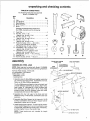
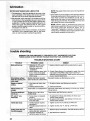
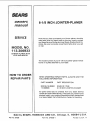
Save This Manual
For Future Reference
SEARS
MODEL NO.
1 "l3.206933
JOINTER/PLANER
WITH
LEGS AND MOTOR
Serial
Number
Model and serial
number may be found
on a plate attached
to your base,
You should record both
model and serial number
in a safe place for
future use.
CAUTION:
6-1/8-iNCH
Read GENERAL
and ADDITIONAL
SAFETY
iNSTRUCTiONS
carefully
Sold
by SEARS,
Part No. 67096
JOINTER-PLANER
® assembly
• operating
e repair parts
ROEBUCK
AND
CO.,
Chicago,
IL. 60684
U.SoA,
:Prir_ted Lr_U_S
general safety instructions for power tools
1. KNOWYOUR POWER TOOL
Readand understand the owner's manual and
labels affixed to the too!. Learn its application
and limitations as we_l as the specific potential
hazards peculiar to this tool.
2. GROUND ALL TOOLS
This tool is equipped
with an approved
3-conductor cord and a 3-prong grounding type
plug tofit the proper grounding type receptacle.
he green c0nductor inthe cord is the grounding
wire. Never connect the green wire to a live
terminal.
3. KEEP GUARDS IN PLACE,
in working order, and in proper adjustment and
alignment.
4. REMOVE ADJUSTING KEYS AND WRENCHES
Form habit of checking to see that keys and
adjusting wrenches are removed from tool before
turning it on.
5. KEEP WORK AREA CLEAN
Cluttered areas and benches invite accidents,
Floor must not be slippery dueto wax or sawdust.
6. AVOID DANGEROUS ENVIRONMENT
Don't use power tools in dam p or wet locations or
expose them to rain. Keep work areawell lighted.
Provideadequate surrOunding work space,
7. KEEP CHILDREN AWAY
All visitors should be kept a safe distance from
work area.
8. MAKE WORKSHOP CHILD-PROOF
-- with padlocks, master switches, or by removing
it will do the job better and safer at the rate for
which it was designed.
10. USE RIGHT TOOL
Don't force tool or attachment to do a job it was
not designed for.
11. WEAR PROPER APPAREL
Do not wear loose clothing, gloves neckties o[
ewelry (rings, wrist watches) to get caught in
moving parts. Nonslip footwear is recommended,
Wear protective hair covering to contain tong
hair, Roll long sleeves above the elbow.
12, USE SAFETY GOGGLES (Head Protection)
Wear Safety goggles (must comply with ANSI
Z87,1) at all times. Everyday eyeglasses only
have impact resistant lenses, they are NO1-
safety glasses. Also. use face or dust mask if
cutting operation is dusty, and ear protectors
(plugs or muffs) during extended periods of
operation.
13. SECURE WORK
Use clam ps or a v_se to hold work when practical.
it's safer than using your hand, frees both hands
to operate tool.
14. DON'T OVERREACH
Keep proper footing and balance at alt times.
15. MAINTAIN TOOLS WITH CARE
Keep tools sharp and clean for best and safest
performances, Follow instructions for lubricating
and changing accessories.
16. DISCONNECT TOOLS
before servicing;
when changing accessories
such as blades, bits, cutters, etc.
17. AVOID ACCIDENTAL STARTING
Make sure switch is in "OFF" position before
plugging in.
18. USE RECOMMENDED
ACCESSORIES
Consult the owner's manual for recommended
accessories. Follow the instructions that accompany the accessories. The use of improper accessories may cause hazards.
19. NEVER STAND ON TOOL
Serious injury could occur if the tool is tipped or
if the cutting tool is accidentally contacted. Do
not store materials above or near the too! such
that it is necessary to stand on the tool to reach
them.
20. CHECK DAMAGED PARTS
Before further use of the tool. a guard or other
part that is damaged should be carefully checked
toensurethat it will operate properly and perform
its intended function. Check for alignment of
moving parts, binding of moving parts, breakage
of parts, mounting, and any other conditions that
may effect its operation. A guard or other part
that is damaged should be properly repaired or
replaced.
21. DIRECTION OF FEED
Feed work into a blade or cutter against the
direction of rotation of the blade or cutter only.
22. NEVER LEAVE TOOL RUNNING UNATTENDED
Turn power off. Don't leave too! until it comes to
a complete stop.
additional safety instructions for jointer-.planer
Safety is a combination
of operator common sense and
alertness at all times when the Jointer-Planer
is being
used.
WARNING: FOR YOUR OWN SAFETY, DO NOT ATTEMPT TO OPERATE YOUR JOINTER-PLANER
UNTIL
IT IS COMPLETELY
ASSEMBLED AND INSTALLED
ACCORDING TO THE INSTRUCTIONS.,
. AND UNTIL
YOU HAVE READ AND UNDERSTOOD
THE FOLLOWING.
PAGE
1. GENERAL SAFETY INSTRUCTIONS
TOOLS .....................................
2. GETTING
FOR POWER
2
TO KNOW YOUR JOINTER-PLANER
3. BASIC MACHINE
OPERATION
4. USE OF HOLD-DOWN/PUSH
5. MAINTENANCE
6. STABILITY
................
BLOCKS
.............................
11
17
.........
18
19
OF MACHINE
If there is any tendency for the Jointer=Planer to tip
over or move during certain operations such as when
pJaning or jointing long heavy boards, the Jointer =
Planer (stand) should be bolted to the floor.
7. LOCATION
The Jointer-Planer
should be positioned so neither
the operator nor a casual observer is fo rced to stand in
line with the wood while it is being planed.
This machine is intended for indoor use only. Provide
adequate lighting.
8. KICKBACKS
Kickbacks can cause serious injury. A kickback occurs
when the operator looses control of the workpiece
causing it to be kicked back toward him.
Kickbacks- and possible injury from them can usuaf_y
be avoided by:
a, Holding
fence.
the workpiece
firmly
against
tables and
b. Not taking too deep a cut at one time, A deep cut
req uires more effort to feed the wood while planing
and can cause the wood to kickback. A cut between
1/32 and 1/16 of an inch deep wil_ produce the best
results.
C,
Not jointing, planing, or beveling
smaller
manual,
Smaller
or into
toward
pieces of:wood
than recommended. (See section in this
"Basic Jointer_Piane_r operations,
')
pieces of wOOd can tip over on the tables;
the cutter head and can be kicked back
you,
d, Keeping blades sharp. Blades that are dull or
nicked require more effort while p_aning and wlli
tend to pound the wood rather than cut it, which
can cause the wood to kickback. A nicked blade will
cut a ridge in your wood and cause the wood to ride
up on the outfeed table. Make sure the cutter blades
are installed properly, and cutter blade wedge
screws are tight.
9_ PROTECTION:
EYES, HANDS, FACE, EARS, BODY
a. If any part of your jointer is malfunctioning,
has
been damaged or broken
. . such as the mo:or
Switch, or other operating controF, a safety device
or the power cord..,
cease operating immediately
until the particular part is properly repaired or
replaced
b. Wear safety goggles that comply with ANSI Z87.1
and a face shield if operation is dusty. Wear ear
plugs or muffs during extended periods of operation,
c. Do not plane, joint, or bevel wood shorter than 12
in. Smaller pieces of wood can tip over on the
tables, or into the cutterhead and be kicked back
toward you.
d. Always use the hold down/push block when j ointing
or beveling wood narrower than 3 in. but never joint
or bevel wood narrower than 3/4 in., or less than t/4
inch thick.
e. Always use the hold down/push
blocks when
planing wood thinner than 3 in. but never piane
wood thinner than 1/2 in. under any circumstances.
f. Avoid awkward hand positions, where a sudden
slip could cause a hand to move into the cutters.
g. Never turn your Jointer-Ptaner "ON" before cleadng
the table(s) of all objects (toots, scraps of wood,
etc.) except for the workpiece and related feed or
support devices for the operation planned.
h. Make sure the cutterhead
revolves in the right
direction, (toward the infeed table).
i. KEEP CUTTER GUARD IN PLACE AND OPERATING PROPERLY AT ALL TIMES. Regularly check
the tension of the cutter guard spring to assure
satisfactory operation. (See Getting To Know Your
Jointer-Ptaner section.)
j. Always feed the wood completely
through the
cutter head and past the cutter guard so that the
guard returns to the rest position against the fence,
When using only one hold down/push Mock to feed
the wood, do not place your other hand on the
Jointer-Planer.
k. Always maintain complete control of the work piece
and provide adequate support for iong and heavy
workpieces.
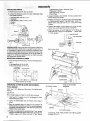
I0, Warped wood should be surface planed on the concave
side for best resutts_
11. To avoid a rough planed surface, determine if possible,
which way the grain emerges from the wood and feed
the wood accordingly.
GRAIN
EMERGING
ROTATION
!2, Do not plane edges of plywood, composition materials,
or wood that has gtue o,n it or is painted or varnished.
Planing these materials will dutl the blades quickly.
3
ns for jointer-pmaner
beyond
the :desired
15. Never leave the Jo
" work area:with the
power on, before the Jo nter-Planer has come to a
complete stop; Or without removing and storing the
switch key. :
EN USED WITH A 3450 RPM MOTOR,
NEVER
SUBSTITUTE OTHER PULLEYS TO INCREASE THIS
SPEED BECAUSE iT COULD BE DANGEROUS.
WARNING: DO NOT ALLOW FAMILIARITY
(GAINED
FROM FREQUENT USE OF YOUR JOINTER-PLANER)
BECOME COMMONPLACE.
ALWAYS REMEMBER
THAT A CARELESS FRACTION
OF A SECOND
IS
SUFFICIENT TO INFLICT SEVERE INJURY.
19. Read and follow the instructions
danger label on the cutter guard.
appearing on the
t6: Never operate the Jointer-Pla ner with protective cover
on the unused shaft end of the motor removed.
DANGER
17. Do not attempt to perform an abnormal or little-used
operation without study and the use of adequate hold
downtpush blocks, jigs, fixtures, stops, etc.
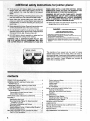
WEAR
FOR YOUR OWN SAFETY
READ AND UNDERSTAND
OWNER'S
MANUAL SEFORE OPERATING
MACHINE
1. WEAR SAFETY
18: DO NOT perform layout, assembly, or setup work on
the table white the cutting _ool is rotating,
WARNING_ THE 2" JOINTER-PLANER
PULLEY AND
THE 2-1/2" MOTOR PULLEY FURNISHED
WILL RUN
THE CUTTER HEAD AT APPROXIMATELY
4300 RPM
-
GOGGLES
PER ANSI Z87.f
AT ALL TIMES.
2, NE_VER PERFORM A JOINTING
OR PLANING
HEAD OR DRIVE GUARD REMOVED.
3. NEVER MAKE
A JOINTING
OR PLANING
OPERATION
CUT DEEPER
THAN
WITH
CUTTER
1/8 INCH,
4, ALWAYS USE HOLD DOWN/PUSH
BLOCKS
FOR JOINTING
MATERIAL
NARROWER
THAN 3 INCP_ES, OR PLANING
MATERIAL
THINNER
THAN 3
INCHES.
YOUR
The operation of any power tool can result in foreign
objects being thrown into the eyes. which can result in
severe eye damage. Always wear safety gogg les complying
with ANSI Z87.1 (shown on Package) before commencing
power too_ operation,
Safety Goggles are available at
Sears retail or catalog stores.
contents
POWER TOOL GUARANTEE
.
. ......
2
GENERAL SAFETY INSTRUCTIONS
FOR
POWER TOOLS ...............
.................
ADDITIONAL SAFETY INSTRUCTIONS
FOR
JOINTER-PLANER
.............................
MOTOR SPECIFICATIONS
AND ELECTRICAL
REQUIREMENTS..
............................
2
3
5
Connecting to Power Source Outlet .............
Check Motor Rotation .........................
UNPACKING AND CHECKING CONTENTS
.........
ASS EM B LY .....................................
5
5
6
7
Assembling Steel Legs ........................
7
Mounting Jointer-Planer
On Recommended
Craftsman Leg Set ..........................
8
Checking Cutterblades and Screws ..............
Mounting Switch ..............................
9
Installing Motor, Pulley, V-Belt and Belt Guards...9
Installing Sliding Guard ......................
10
GETTING TC) KNOW YOUR JOINTER-PLANER.
,o, .11
DePth of CutHandWhee_
4
. :. _...
,_ ....
....
;* -o ! 1
Fence
Fence
Cutter
Infeed
On-Off
Locks and Stops ......................
Tilt Scale ............................
Guard ...............................
Table ................................
Switch ..............................
12
12
13
14
16
BASIC JOINTER-PLANER
OPERATION
...........
Feeding the Workpiece ........................
Using the Hold Down/Push Blocks .............
Beveling ...................................
MAINTENANCE
................................
Replacing Cutter Blades .....................
Installing Cutter Guard Spring ................
Sharpening Cutter Blades ....................
GENERAL MAINTENANCE
......................
LU BRfCATI ON .................................
MOTOR MAINTENANCE AND LUBRICATION
......
TROUBLE-SHOOTING
..........................
17
17
18
19
19
19
21
23
23
23
24
24
REPAIR PARTS ................................
RECOMMENDED
ACCESSORIES .................
26
31
motor specifications and electrical requirements
This machin6 is designed to use a 3450 RPM motor only.
Do not use any motor that runs faster than 3450 RPM. It is
wired for operation on 110-120 volts, 60 Hz., atternating
current, IT MUST NOT BE CONVERTED TO OPERATE
ON 230 VOLTS. EVENTHOUGH SOME OFTHE RECOMMENDED MOTORS ARE DUAL VOLTAGE.
THESE CRAFTSMAN MOTORS HAVE BEEN
FOUND TO BE ACCEPTABLE
FOR USE ON
THIS TOOL.
HP
RPM
VOLTS
CATALOG
1/2
1/2
3/4
3/4
3450
3450
3450
3450
110-120
110-220
110-120
110-120
12!6
1218
1219
1226
CONNECTING
TO POWER
SOURCE
It is recommended that you have a qualified electrician
replace the TWO prong outlet with a property grounded
THREE prong outlet.
A temporary
adapter as shown betow is available for
connecting
plugs to 2-prong receptacles.
The green
grounding lug extending from the adapter must be connected to a permanent ground such as to a properly
grounded outlet box.
NO.
CAUTION: Do not use blower or washing machine motors
or any motor with an automatic reset overload protector as
their use may be hazardous.
This machine must be grounded
operator from electric shock.
If the outlet you are planning to use for this power tool is of
the two prong type DO NOT REMOVE OR ALTER THE
GROUNDING PRONG tN ANY MANNER. Use an adapter
as shown and always connect the g rounding lug to known
ground.
A temporary adapter as illustrated is available for connecting plugs to 2-prong receptacles. The temporary
adapter should be used only until a properly grounded
outlet can be installed by a qualified electrician.
OUTLET
GROUNDING
while in use to protect the
Plug power cord into a 110-120V properly grounded type
outlet protected by a !5-amp, dual element time delay or
Circuit-Saver fuse or circuit breaker.
If you are not sure that your outlet is properly
have it checked by a qualified electrician.
grounded,
t
3-PRONG
_L-
LUG
_1
_, _._--'*_-'_-_
PLUG
I ll
/
WARNING: DO NOT PERMIT FINGERS TO TOUCH THE
TERMINALS
OF PLUGS WHEN INSTALLING
OR
REMOVING THE PLUG TO OR FROM THE OUTLET,
MAKE
SURE
CONNECTED
THIS
TO
IS
A
KNOW.
GROU.O
RECEPTACLE
ADAPTER
WARNING:
IF NOT PROPERLY
GROUNDED
THIS
POWER TOOL CAN INCUR THE POTENTIAL HAZARD
OF ELECTRICAL SHOCK. PARTICULARLY WHEN USED
IN DAMP LOCATIONS IN PROXlMITYTO PLUMBING. IF
AN ELECTRICAL
SHOCK OCCURS THERE IS THE
POTENTIAL OF A SECONDARY
HAZARD SUCH AS
YOUR HANDS CONTACTING THE CUTTING BLADE.
WARNING: THE GREEN GROUNDING LUG EXTENDING
FROM THE ADAPTER MUST BE CONNECTED
TO A
PERMANENT GROUND SUCH AS TO A PROPERLY
GROUNDED OUTLET BOX, NOT ALL OUTLET BOXES
ARE PROPERLY GROUNDED.
If power cord is worn or cut, or damaged in any way, have
it replaced immediately.
tf you are not sure that your outlet is properly
have it checked by a qualified electrician.
grounded,
NOTE: The adapter illustrated is for use only if you already
have a properly grounded 2-prong receptacle.
The use of any extension cord will cause some toss of
power, To keep this to a minimum and to prevent overheating and motor burn-out, L_se the table below to
determine
the minimum wire size (A.W.G.) extension
cord. Use oniy 3 wire extension cords which have 3 prong
grounding type plugs and 3-pole receptac}es which wif_
accept the plug on the saw
3--PRONG
PROPERLY
GROUNDED
OUTLET\
Extension
GROUNDING
PRONG
Cord Length
Up to 100 Ft.
100 - 200 Ft.
2OO - 4OOFt
Wire Size A.W.G.
14
12
8
CHECK MOTOR ROTATION
This power too! is equipped with a :?,-conductor cord and
grounding type plug which has a grounding prong listed
by Underwriters_ Laboratories
Association. The ground
conductor has a green jacket and is attached to the tool
housing at one end and to the ground prong in the
attachment plug at the other end.
This ptug requires a mating 3-conductor
outlet as shown.
grounded
type
Place the motor on your workbench
or on the floor.
Standing clear of the motor shaft, plug the motor cord into
a properly grounded outlet. Notice the rotation of the
shaft. As you look directly at the motor shaft it shoutd be
turning in the counterclockwise
direction,_--'_,
if the
motor shaft is turning counterclockwise,
remove the plug
from the power outlet and continue the assembly procedures If the motor isturning clockwise, remove the piing
from the power outlet and contact your Sears Store
immediately.
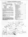
d checking contents
TABLE
-//
7/:16" Wrench
3/4°'_Wrench
3/8" Wrench
__
Medium Screwdriver
M0def:113.206933 Jointer-Planer
is shipped complete
onecarton and INCLUDES Steel Legs, and Motor.
in
Separate all parts from packing materials and check each
onewith the illustration and the list of Loose Parts to make
certain all items are accounted for, before discarding any
packing material.
If any: parts are missing, do not attempt to assemble the
jointer/planer_ plug in the power cord or turn the switch on
until the missing parts are obtained and are installed
correctly.
Remove the protective oil that is applied to al{ unpainted
metal surfaces. Use any ordinary household type grease
and spot remover.
WARNING: Never use gasoline, naptha or similar highly
volatile solvents.
Apply a coat of paste wax to the table.
Wipe all parts thoroughly
with a clean, dry cloth.
WARNING: FOR YOUR OWN SAFETY, NEVER CONNECT
PLUG TO POWER SOURCE
OUTLET
UNTIL ALL
ASSEMBLY STEPS ARE: COMPLETE, AND YOU HAVE
- READAND UNDERSTAND
THESAFETY AND OPERAT| ONAL INSTRUCTION S.
OF LOOSE
PARTS
Item
No.
Description
A Jointer-Planer
..............................
B V-Bett_ 1,/2 x 52 " ............................
*C 5/32 Setscrew Wrench .......................
*D 1/8 Setscrew Wrench ........................
*E Motor Pulley, 2-1/2" Dia ......................
*F Sliding Guard Knob .........................
*G Concave Plastic Washer .....................
H Sliding Guard ..............................
*J Sliding Guard Rod ..........................
*K Nut, 1/2-13 .................................
*L Lockwasher, 1/2 ............................
*M Lockwasher. No. 10 .........................
*N Screw, Pan Hd., 10-32 x 1/4 ...................
O Owners Mariu!! ..............................
*P Depth of Cut Handwheet .....................
*Q Screw, Sems, 1/4-20 x 1-1/4 ..................
R On/Off Power Outlet ........................
*S Washer, 17/64 x 1/2 x 1/32 ....................
"T Lockwasher. External 1/4 ....................
*U Screw, Pan Hd. 1/4-20 x 1/2 ..................
V Jointer-Planer
Belt Guard ....................
*W Attaching Hardware (2 Nuts, 2 Bolts)
X Belt Guard Clips ............................
Y Bracket. Mounting
.........................
Z Beft Guard Support Bracket ..................
AA Bett Guard Support .........................
AB Screw Pan Hd. 10-32 x 1/2 ....................
AC Motor Pulley Belt Guard .....................
AD Switch Key ................................
AE Hold Down/Push Block ......................
AF Fence .....................................
........
Fence ...............................
*Supplied in Loose Parts Bag #507437
Qty.
1
1
1
1
1
1
2
1
1
1
1
2
2
1
1
1
1
2
2
2
1
3
1
1
1
2
1
1
2
I
I
AF
AG
0
A
\
AD
6
AE
\
unpacking and checking contents
TABLE
OF LOOSE
PARTS
TheFollowing
PartsAreIn iudedWith
Model 113,206933 Only
Item
No.
A
B
C
D
E
DescripUon
Leg,
End Stiffener ...............................
Side Stiffener ..............................
Motor Support ..............................
Motor .....................................
Qty.
.4
2
4
1
1
Package of Miscellaneous Small Parts,
No. 67035, Consisting of the Following:
F
G
G
G
H
J
K
K
L
M
N
Cord Clip ..................................
Hex Nut, 1/4 in.-- 20
(approx. dia. of hole 1/4 in,) ................
Hex Nut, 5/16 in,-- 18
(approx. dla. of hole 5/16 in.) ................
Hex Nut, 1/2 in.-- 13
(approx. dia. of hole 1/2 in.) .................
TrussHd. Screw, 1/4in. --20x5/8
tn.
long. (Top of screw is rounded) .............
Flat Washer (dia. of hole 11/32 in.) .............
Lockwasher, 1/4 in. External Type
(approx. dia. of hole 1/4 in.) ................
Lockwasher, 5/16 in, External Type
(approx. dia. of hote 5/16 in.) ................
Carriage Bolt, 5/16 in. -- 18 x 3/4 tong ..........
Leveling Foot ..............................
Hex Hd. Screw, 5/16 in. -- 18 x 2 in .............
ii i,,
i
2
A
40
7
8
G
40
7
40
7
3
4
3
..................................
assembly
ASSEMBLING
STEEL
TRUSS
HD.
SCREW
END
STIFFENER
LEGS
NOTE: Steel Legs are furnished with Model 1t3.206933.
From among the foose parts, find the foilowin 9 Hardware:
END
1/4-201 X LOCKWASHER
_1/: EXTERNAL
40 Truss Head Screws, I/4-20 x 5/8
40 Lockwashers, 1/4-External
40 Hex Nuts, !/4-20
8 Hex Nuts, t/2-13
4 Leveling Feet
/__
STIFFENERS
1. Assemble two (2) Side Stiffeners together Using four
(4) 1/4-20 Truss head screws, tockwasher and nuts.
Make two (2) Side Stiffener assemblies.
I
The End Stiffeners are placed on top and at each end
of Side Stiffener assemblies as shown. Align holes,
letter coded "B" (see page 8) in Side Stiffeners and
End Stiffeners and then insert 1/'4-20 Truss head
screws through the 9/32 diameter hotes and install
Iockwashers and nuts and then tighten.
2. Assemble the four (4) Legs to the Side and End
Stiffeners using 1/4-20 screws, lockwashers and nuts
as sh own,
3. Assemble the Motor Support to the Legs with 1/4-20
screws, Iockwashers and nuts. Motor Support can be
assembled to either end of Leg set.
:/
4. Install leveling feet as shown. To level Leg Set, loosen
nut on inside of leg and turn nut on the outside to raise
or lower feet. Adjust all four leveling feet, if necessary,
and then tighten nuts on the inside of leg.
NOTE: These levelers
adjustment:
are not intended for height
....-._
.....
MOTOR
SUPPORT
LEGS
i
assembly
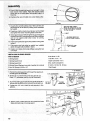
1. Place fence on jointer table as shown.
2_ Locate the following parts from the loose parts bag
and install as shown.
1. CarriageBolt, 3/8-16 x 24/2
2. Retainer
3, Fiat Washer 13/32 x 13/! 6 x 1/t6
4. Spacer
5. =Knob
7 Lockwashers, 5/16 in. External Type
7 Washers, 11/32 ID
7 Hex Jam Nuts, 5/16-18
2 Cord Clips
2. Loosen FENCE LOCK KNOB, Tilt fence upward and
slide it toward the pulley.
3. Position machine on Leg Set and align mounting holer
in machine with holes in Leg Set letter coded "A'.
Mount with three (3) 5/16-18 x 2" Long Hex Head
Screws.
4. Place a flat washer, a tock washer and a nut on each
screw from underneath the stand and tighten.
[E
5. Place handwheet on shaft aligning flat surfaces on
shaft with flat surfaces on handwheel..,
attach with
1-1/4 in. screw.
_1_
/
JOINTER
;PLANER
HEX HEAD
SCREW
1
1
2
JOINTER
eASE
SPECIAL NOTE: It is a good _dea at this point to see if the
infeed table and Outfeed table are paraltel to each other. If
it is necessary to align the two tables the procedure used
to make them parallel can be more easily performed now,
before mounting the jointer/planer to the leg set, Refer to
page 14 for directions explaining how to check and align
the infeed and outfeed tables.
MOUNTING
Jl
HEXNOTff'_
FENCE
LOCK
KNOB
JOINTER-PLANER
1. From among the loose parts, find the following
ware:
hard-
4Carriage Bolts, 5/16-18 x 3/4
3 Hex Head Screws, 5/16-18 x 2
DEPTH
_/4-_0
HEAD
TRUSS
SCREW
SIDE STIFFENER
FLAT WASHER
(AS REQUIRED)
OF CUT
EL
..
LOCKWASHER
---
MOTOR
SUPPORT
AT THIS
11
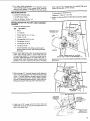
CHECKING
CUTTER
BLADES
END
NUT
OUTFEED
Setscrew
5/32 IN. SETSCREW
WRENCH
AND SCREWS
TOOLS NEEDED
5/32" and 1/8"
Jointer).
Lead Pencil
----"_
1
Wrenches
(furnished
Short straight edge (or head of combination
TABLE
with
WEDGE
square)
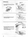
1. Insert pencil in space at end of cutterhead
cutterhead guard open.
to hold
2. Lower the infeed table with the Depth of Cut Handwheel.
3. Rest the straight edge on edge on the surface of
outfeed table so it extends across the opening between
the tables, at three positions: near each end and at the
middle of the cutter blade.
4. Rotate the cutterhead by grasping the 2" dia. driven
pulley and make sureeach knife nicks (touches) the
straight edge at all three positions.
If not, follow
8
BLADE
PENCt L
\
CUTTER GUARD
procedure
under "REPLACING
on pgs, 19 thru 21.
CUTTER
BLADES"
5. If a cutter blade adjustment is not required, check
each locking screw of each wedge (5/32" setscrew
wrench) and tighten if necessary. Hold the pulley
,i
i
MOUNTING
while tightening
fingers do not slip
--
SWITCH
2 Lockwash_rS,
1, Locate the following
parts:
2 Washers,
1 On/Off Power Outlet
i
MOTOR,
PULLEY,
1. Locate the following
QIy.
IE;<te real 1/4
17/64
2. Attach On/Off
holes.
2 Pan Hd. Screws, 1/4-20 x 1/2
INSTALLING
GUARDS
screws
and be careful that your
off the wrench-
× 1/2 x 1732
out|et
to infeed table using two _apped
L __
V-BELT
AND BELT
parts:
Description
1
Motor
1
"L" Bracket
1
1
Pulley (Approx. 2-1/2" Dia.)
V=Belt 1/2 x 52
4
4
Carriage Bolt 5/16-18 x 3/4
Fiat Washer 5/16 i.D.
4
Lockwasher5/16
4
Hex Nut 5/16-!8
1
Guard Assembly _nctuding a guard support,
guard support bracket, self-threading screws,
and clips,
CARRIAGE BOLT
5/16-18 x 3/4
I.D.
MOTOR
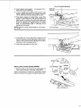
2. Place motor against the motor mounting bracket and
insert bolts through holes in motor base and then
through holes marked "X" in motor mounting bracket.
DO NOT TIGHTEN BOLTS AT THiS TIME. The "L"
bracket which holds the guard support must be slid
between the motor base and the motor mounting
ti
VtEW
FROM
BOLTS
GO
THRU
bracket somotor
at this time.
BACK
OF JOINTER
HOLES
MARKED
"X"
rn u st be loosely assembled to bracket
iii,
IH
i, iiiiiiii, ii
(
TWO
HOLES
CLOSEST
3. Slide long leg of "L" bracket between motor base and
motor mounting bracket. Then sandwich the short leg
of the "L" bracket between the guard support bracket
and the guard support and loosely fasten together
with self-threading
screws as shown. Install clips onto
bett guard support with long end of clip facing you.
10-32 X 1/2 IN,
SELF-THREADING
suP.oRT
L¸ i_ j
ill!
i
i
i
i
i
!l
,
i
iiiiii
i
_
2"!/2
5/32 INCH
SETSCREW
WRENCH
'° MOTOR
url
II I
PULLEY
TIGHTEN
S_T SCREW
AGAINST
FLAT
,ON
SHAFT
4. Install the 2-1/2" pulley onto the motor shaft and
t_ghten the set screw in the pulley hub against the flat
part of the motor shaft.
HERE
MOTOR
WITH
SHAFT
9
assembly
.
,
. 5/Push V_Belt through belt guard just enough to loop
belt aro'uhd motor pulley_ Place bett: around m0t()r
pu ey but don0t push guard onto guard support at
:
thistime.
"
- 6: Position
other end of V-Belt
onto cutter head pulley.
OPEN
/
,
i
i
END
i
7. Visually line up both pulleys and V-Belt until they are
perpendicular
to the floor by sliding motor sideways
as needed,
PULLEYS
C_____
8. Pressdown hard on motor to put tension on the V-Belt
and tighten the motor mounting bolts at this time.
AND
V-B ELT
j_MUST BE STRAIGHT IN-LINE
_AT
90° WITH RELATIONSHIP
TO THE FLOOR
!
t
9. Checkguard
support before tightening guard support
screws to be sure it is centered around motor shaft and
will not rub against shaft when motor msrunning.
Tighten screws,
,----V-BELT
.....
GUARDS
REMOVED
FOR PICTURE
CLARITY
!
10. Push motor pulley belt guard into position onto guard
support.
tl.
Plug motor cord into outlet on switch
earlier through hole provided in stand.
12. Fasten cord along front
cord clips.
i
INSTALLING
i
SLIDING
box installed
i,
//
side stiffener using the two
....
t
90°_,]
iJ,
STRAIGHT
\ ,
[
LNE
UP--DOWN
_
ill
i
GUARD
PARTS NEEDED
2 Hex Nuts 1/4-20
1 Sliding Guard
1 Hex Nut 1/2 in. - 13
1 Sliding Guard Knob
1 Split Iockwasher
I Sliding Guard Rod
2 Ext. tooth
2 Sliding Guard Washers (one side of washer is concave)
2 Hex Hd. Screws 1/4-20x 1/2"
2 10-32 x 1/4 Pan Hd. Screws
1/2 in,
Iockwashers
1 Belt Guard
1/2"
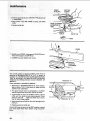
_I,POsitiOn the siiding:guard rod through the opening in
the belt guard as illustrated.
HEX NUT
1/2" LOCKWASHER
2. Screw 1/2 °' nut alt the way onto long end of rod...
\_
BELT
GUARD
place 1/2" Iockwasher next to nut (as illustrated),
3, Screw the sliding guard rod into the jointer as far as it
witl go with the short end of rod pointing straight up.
4. Tighten the 1/2" nut to hold the rod securely
position.
in this
5. Attach guard to stand with hex hd. screws and nuts,
Make sure belt does not scrape guard,
10
1/2"
X
_/i/4_:__/
t
HEX NUT
[i _/
_
.//_
GUARD
\SLIDING
GUARD
ROD
/
t
ROD
SLIDING
GUARD KNOB
6. Attach sliding guard to fence
screws and Iockwashers.
with two pan head
10-32xl/4
7. PtaceoneSIidingGuardWasher,
on support rod.
concaveside DOWN
EXT. TOOTH
LOCKWASHERS
_,^o==o,,M=,,,_,_ '
(CONCAVE S|DE UP)
SCREWS'_',,_
8. Drop sliding guard onto rod..,
place other washer,
concave side UP on rod.. _screw on Sliding Guard
Knob.
i,, u,i
i llUl
,1=
== ===LI
H
i
i
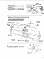
getting to know your jointer-planer
WARNING: FOR YOUR OWN SAFETYTURN SWITCH
"OFF" AND REMOVE PLUG FROM POWER SOURCE
OUTLET BEFORE MAKING ANY ADJUSTMENTS.
FENCE
SCALE
(BEHIND TILT
FENCE)
2
FENCE
SLIDING GUARD
OUTFEE{)
FENCE
LOCK
KNOB
BACK OF
JOINTER
TABLE
F
KNOB
INFEED
TABLE
SLIDE
BRACKET
!
FRONT
OF
\,
%
4
CUTTER
GUARD
6
ON-OFF
SWITCH
1
1NFEED
TABLE
..41
= DEPTH OF CUT HANDWHEEL
Turning the handwheel counterclockwise will lower the infeed table
to maximum depth of 1/8 in.
DEPTH OF CUT
HANDWHEEL
DEPTH OF CUT
HANDWHEEL
I
JOINTER
/
_"_---_+.'
UP
/.i
/
DOWN
I"1
-
=
FENCE
LOCKS
AND
_
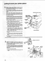
STOPS.= The fence can be
moved across the Jointer to take full advantage of
1he "sharpness_' Of the blades.
Thb fence should be positioned to the extreme right
(toward pulley) but not beyond the end of the
blades.
Most of the cutting (usually jointing) will be done
w_th thefence in this position, As the blades become
.dull, the fence can be moved toward the left where
the blades are sharper,
-.
•
To move the fence, loosen the Fence Lock Knob and
the Sliding Guard Knob and slide to desired position.
Make sure SLIDE BRACKET is even with surface of
OUTFEED TAB LE. If it is above or below the surface,
loosen screws and adjust it.
a. Always tighten fence lock knob first
fence, then tighten sliding guard knob.
g0 ° to tables, loosen the two
so the stop springs back into
back so the stop rests on the
both knobs.
e. 45 ° Fence Stop positions
tables.
GUARD KNOB
PUSH DOWN
WHEN LOCKING
FENCE LOCK KNOB
FENCE
45°FENCE
STOf
to align
b. Before tightening
fence lock knob, hold fence
down on outfeed table so it does not rock.
c. 90 ° Fence Stop positions fence square to tables.
TO tilt fence, loosen the fence lock knob and
sliding lock knob and pull the stop out. Tilt to
desired angle and tighten both knobs.
d. To set fence at
knobs, tilt fence
place. Tilt fence
table and tighten
SLIDING
_°FENCE
STOP
FENCE LOCK
KNOB
.
\
\
SLIDE BRACKET
the fence at 45 ° to the
f. To tilt fence to 45 ° loosen the two knobs, pull 90 °
stop out, t It:fence so the 45 ° stop rests on the
table.
g. Ho d fencedown
twokn0bs:
on outfeed table and tighten the
" " :
' : :
i
i
i
i
ii
i
i
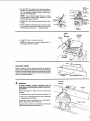
._..---FENCE TILT SCALE
.
FENCE TILT SCALE. Indicates tf_e angle of the
fence to the tables. When the 90 _ fence stop is
correctly adjusted, the fence will be 90 ° to the table
and the scale will read 90 °.
To check for squareness, place an accurate square
on infeed table and check fence while locked at 90 °
position. MAKE SURE 90 ° STOP IS AGAINST SLIDE
BRACKET.
SQUARE
FENCE
FACE
If fence is not square to table:
a. Slightly loosen fence lock knob and guard lock
knob ....
/
"
12
CUTTER
GUARD
1NFEED
TABLE
SCALE
ADJUSTING
b. Loosen 90° stop screw with small screwdriver
and turn knurled sleeve which will cause fence to
tilt, Turn sleeve in either direction until fence is
square with infeed table.
NOTE: If you cannot square fence by turning
knuded sleeve, loosen three screws "A" and
adjust fence square to table.
c. Tighten
knobs,
90° stop Iockscrew and both fence lock
d, If 90 ° reading on tilt scale does not line up with
top surface of the slide bracket, loosen screws
holding scale and move it... tighten screws.
SCREW
_s
90° STOP
KNURLED
TiLT
SCALE
zF
45 = STOP
o sToP
LOCKSCREW
45_'STO_
'gO '_ STOP
LOCKSCREW
J_
SLEEVEN_(
SCALE
AD3USTING
SCREW
90 e STOP
BRACKET
HEAD
OF
SQUARE
INFEED
TABLE
FENCE
e. Adjust 45° stop in the same manner.
NOTE: Tilt scale wilt not require adjustment
was adjusted for 90 ° position.
if it
CUTTER
GUARD
AUXILIARY
FENCE
Some on-edge and other jointing operations require a
high er and/or Ionge r fence than you r tool provides. Select
a piece of smooth straight wood of the height and length
required for proper support and bolt it to the tool fence as
shown for these operations,
11
1/4-20 FLAT
HEAD
SCREW
COL
CUTTER
GUARD
WARNING:
CUTTER GUARD. Provides protection over the
cutter head. It must always be in PlaCe and functioning properly. ....
FENCE
Check the guard to make sure it is functioning
properly.
a. Position fence to right for maximum
width of cut.
b. Pass a 1/4 in. thick piece of wood over cutterhead
between guard and fence,
Guard must return automatically
to "rest position"
against fence when free of the wood,
tf guard does not return automatically,
Shooting and Maintenance Sections.
see Trouble
INFEED TABLE
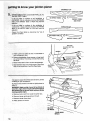
to know your jointer.planer
CROWNED CUT
A
ALWAYS BE PARALLEL TO
or
lrfac. _ of the w0rkpiece is
an
iicati on that the OUTWARD
qFEED table is HiGH and must be
or surface of the workpeice is
CONCAVE, it is an ind tcation that the OUTWARD
END of the fNFEED table is LOW and must be
adjusted.
Check the infeed table to determine the "out of
parallel" condition.
CONCAVE CUT
INFEED TABLE LOW
i l
]
a, Insert a penciHn space at end of cutterhead
hold cutterguard open.
w,y
PENCIL
to
",
b, Place astraightedge
(large square or long level)
on outfeed table. First along one side than along
theother.
C. Raise infeed table until it touches straightedge.
d. Sight between tabte and straightedge to determine
high or!ow condition of end of infeed table.
=
TABLE
_
=ll
it iseasier to adjust the infeed table while the Jointer
is setting on your workbench.
Do not turn the3ointer
adjust it.
on its side or upside down to
WARNING: Attach a strip of wood to two blocks of
wood 10 in. high. Drive enough nails into thestrlp so
that Jointer does not ti p over while resting on blocks
causing possible injury,
a. Remove motor cord from outlet in switch box.
b. Remove Jointer pulley guard and V-belt.
c. Remove Jointertrom
stand.
d. Place Jointer on blocks.
OF WOOD
YOUR WORK
BENCH
_-_" J__
e. Insert a pencil in space at end of cutterhead
hold cutterguard open.
to
f. Wrap a piece of cardboard around cutterhead to
protect your fingers and the btades..,
sec_ure
cardboard with a piece of tape.
CARDBOARD-
h. Loosenfourlockscrews
wrench.
2 or3turns
J
withl/2in.
LEVELING
STUDS
LOCKSCREWS
VIEW LOOKING UP FOR PARTS IDENTIFICATION
Turning the LEVELING STUDS will RAISE or LOWER
the infeed table.
\
SCREWING in the studs will RAISE the table ....
UNSCREWING them wilt LOWER the table.
a. With a 3/4 in. wrench turn leveling studs until
infeed table is parallel with straightedge.
b. While holding studs with wrench, TIGHTEN all
four LOCKSCREWS...
tighten each screw a little
bit at a time until alt four screws are tight.
c. Recheck with straightedge to make sure infeed
table (in raised and lowered positions) is parallet
to ouffeed table.
15
j'ointer- pianer
be turned
=ched or bumped,
OFF"by
striking
e hand.
n" is a key, when inserted in the
turned ON and OFF.
it is removed, the power cannot be turned ON.
THIS FEATURE
tS INTENDED
TO PREVENT
UNAUTHORIZED
AND POSSIBLE HAZARDOUS
USE BY CHILDREN AND OTHERS.
NOTE:
a. Insert Key into switch,
Key is made of vellow
plastic.
NOTE: Key is made of yellow plastic,
b. TO turn machine on, insert finger
lever and pull end Of switch out.
i
under switch
i
c, To turn machine OFF
PUSH lever in.
Never leave machine unattended
come to a complete step.
until
it has
HOLD
d. TO lock switch in OFF position .. : hold switch IN
with onehand ... REMOVE key with other hand.
WARNING: FOR YOUR OWN SAFETY, ALWAYS
LOCK THE SWITCH "OFF" WHEN MACHINE
IS
NOT IN USE...
REMOVE KEY AND KEEP tT IN A
SAFE PLACE,.,
ALSO...
IN THE EVENT OF A
POWER FAILURE (ALL OF YOUR LIGHTS GO
OUT) TURN SWITCH OFF...
AND REMOVE THE
KEY. THIS WILL PREVENT THE MACHINE FROM
STARTING UP AGAIN WHENTHE POWER COMES
BACK ON.
PULL
\
MOTOR
CORD
t
e. Plug motor cord into outlet in switch box,
OUTLET
POWER
CORD
--
i
i
_1 ii
___
basic jointer-planer operation
the cutterhead
WARNING: For your own safety, ALWAYS use the hold
down/push
blocks when JOINTING
wood that is
NARROWER than 3 tn.... or when PLANING wood that is
THINNER than 3 in.
For your own safety, never operate this tool with the fence
or guards removed.
For best results, take light cuts. For average planing,
jointing, or beveling, a cut between t/32 and t/16 in. deep
will produce the best results.
Do not plane, joint or bevel wood shorter than 12 in.
Material this short is more difficult to control while being
cut. S mall pieces of wood can tip over on the tables or into
,
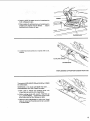
FEEDING
,
,
and can be kicked back toward you.
i
THE WORKPIECE
Hold the board firmly DOWN on both tables and AGAINST
the fence..,
keep fingers close together.
Feed the boa rd at a continuous even rate of speed u ntil the
cut is made along the entire length of the board. Any
hesitation or stopping could cause a "step" to be cut on
the edge of the board which would cause the board to ride
up on the outfeed table resulting in a "crooked" edge on
the board.
JOINTING
WOOD THAT IS WIDER THAN 3 IN.
i1,1 , iiil,,irl
As the RIGHT hand passe s over the cutterhead, remove
the LEFT hand...
CONTINUE feeding while placing the
LEFT hand behind the RIGHT. Continue feeding in this
manner "hand over hand", until the entire length of the
board is cut. Pressure should be applied over the cutterhead and outfeed table.
DO NOT FEED TOO FAST. A stow steady: rate of feed
produces a smooth accurate cut. Feeding too fast causes
a "rippled" cut,., makes it difficult to guide the workpiece
accurately and could be hazardous.
....
PLANING WOOD THAT IS THICKER
i i
iiii
iii1,1
i
THAN 3 IN.
,HI
SUPPORT LONG WORKPIECES
17
basic jointer-planer
operation
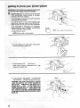
WITH THE GRAIN
ROTATION
_ver 1
natu
AGAINST
slowly,
THE
GRAIN,
take very light cuts and feed
AGAINST THE GRAIN
ROTATION
USING
THE
HOLD
DOWN!PUSH
BLOCKS
ALWAYS use the hold down/push blocks when JOINTING
wood that is NARROWER than 3 in. or planing wood that is
thinner than 3 in. (as illustrated).
Grasp the hold down/push blocks firmly with the fingers
close together and wrapped around the handle. Position
them flat on top of workpiece, and push the workpiece
down against the table to provide a quality cut and
minimize the chance of a kickback.
Hold-down
pressure must also be sufficient to prevent
hold-down/push
block sliding or slipping on the top face
of workpiece when advancing workpiece over c utter head.
Use a hand over hand motion of the hold down/push
blocks being careful to maintain control over the workpiece
at all times:
JOINTING
WOOD NARROWER THAN 3"
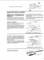
%
This means that once the workpiece has been fed past
cutter head onto outfeed table, one hold down/push block
must always maintain contact of work piece with ouffeed
table.
WARNING: If the HOLD DOWNIPUSH
BLOCKS tend to
slip while feeding, Clean rubber surfacelmmediately
with
sandpaper.
_:
PLANING
WOOD
i
Z
When planing wood 3/4 in. thick and NARROWER than
the hold down/push block, tilt the hotd down/push block
so that it clears the top of the cutterguard while feeding,
Never plane wood that is thin net than 1/2 in .... because it
sapt to spiitor shatter and th us has a greater ten dency to
kickback.:
- "
k
18
THINNER
THAN
3"
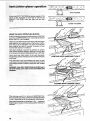
BEVELING
Adjust the fence to the desired angle..,
guard lock knobs ......
tighten fence and
For pieces of woo d 3" or wider hold the board firmlydown
on both tables and firmly against the fence (as illustrated)
with your hands on the side and top of the workpiece,..
keep finge_s close together.
NOTE: Removing only the corner on the edge of a board is
known as CHAMFERING while beveling is removing the
corner or the edge of the board down to the boards
surface.
Normally a chamfer is made with one cut,.,
cut deeper than 1/16 in. may be made,
therefore,
a
For pieces of wood less than 3" wide use hold down/push
blocks (as illustrated) on the side of the workpiece so you
can hotd the workpiece in toward the fence at all times as
well as down against the table top.
WARNING: DO NOT CONTACT THE CUTTING
OR THE GUARD WITH THE PUSH BLOCKS.
CHAMFER
BEVELING
BOARD
WIDER
THAN
3 INCHES
KNIVES
BEVEL
BEVELING BOARD NARROWER THAN 3 iNCHES
NOTE: Rabbeting on a Jointer is considered to be a
dangerous operation because it requires removal of the
cutter guard and increases the potential of kickback
because of excessive depth of cut .....
NEVER ATTEMPTTO PERFORM A RABBETING OPERATION ON THIS JOINTER. DO NOT OPERATE JOtNTER/
PLANER WITH CUTTERHEAD
OR BELT GUARDS
REMOVED.
Rabbet cuts should be made on the Radial Saw or Tabte
Saw by making two cuts with the sawblade or by using the
Dado Head or Molding Head. Rabbet cuts can also be
made using the Shaper or Portable Router.:
i
=
,
::i•
IHUlhUlN
CUTTER
........
BLOCK OF WOOD
i
/
maintenance
REPLACING
RABBETCUT
BLADES
WARNING: FOR YOUR OWN SAFETY, TURN SWITCH
"OFF" AND REMOVE PLUG FROM POWER SOURCE
OUTLET BEFORE ADJUSTING,
MAINTAINING,
OR
LUBRICATING YOUR JOINTER-PLANER,
1. Remove be!t guard.
2. Position fence to right
beyond cutter blades..,
,..
approximately
lock it in place,
1/4 in,
3. Lower infeed table all the way down,
4. Place block of wood 6-3/4 in, long between
guard and fence:
cutter-
19
HOLD PULLEY
FIRMLY
5. Hold cutterhead
pulley firmly with one hand and
loosen iockscreWs in each wedge using a 5/32 in.
Setscrew wrench.
BLADE
LIFTER
SCREW
5/32 IN.
SETSCREW
WRENCH
CLOCKWISE
LOOSEN
WEDGE
LOCKSCREW
FENCE NOT SHOWN
FOR PICTURE CLARITY
i
j
SMALL SCREWDRIVER
6. While holding Cutterhead pulley firmly with one hand,
gentlypry
up each Wedge using a screwdriver
. .
remove wedges and blades.
!
7. Remove the six lifter screws. (Two under each blade.)
8. Clean cutterhead, weoges and screws thoroughly with
Craftsman Gum and Pitch Remover. also remove the
oil from new blades.
9. Replace the six lifter screws and screw them in all the
way, but do not tighten. Mark each slot 1,2, and 3. This
witl help you in setting the blades.
CUTTER HEAD '
SETSCREW
MARK SLOTS
1, 2 AND 3X
!/8 IN. SETSCREV
WRENCH
2O
I/8
10. Insert a blade in slot marked I .,. so it projects t/16 in.
beyond end of the cutterhead,
11. "Insert a wedge next to blade so the flat side of the
wedge is against the bla(_e. Push wedge in manually
-do not install two locking setscrews at this time."
IN, SETSCREW
HEAD OF
SQUARE
WRENCH
........
OUTFEED_
!2, Place head of square on outfeed table. Loosen lifter
screws to raise blade until it just touches square and
slightly raises it. Gently turn cutter head back and
forth with the pulley while raising blade. The blades
should be adjusted just slightly above the cutfeed
table, by approximately .003 in. (thickness of an
average piece of paper).
NOTE: Sears has a knife setting
Cat. #9-2647
gauge for this purpose.
LIFTER SCREW
......
ii
,lllllr,i
!iN,llll ii iii i
13. "Now install both locking setscrews and tighten (with
the 5/32" setscrew wrench) alternately a little at atime.
Tighten both screws securely. Recheck the blade to
make sure it did not change position."
14. Install other two blades the same way.
INFEE
/
INSTALLING
CUTTER
GUARD
SPRING
t. Remove cotter pin from pivot pin in cutter guard and
remove guard (located u_derneath infeed table).
Spring must appear as in sketch from underside of infeed
table, it will not perform properly if nsta ed upside down.
FLAT WASHER
_zSPRtNG
_"-'-_
!_
SUPPORT
_ LOCK
_-_ 7"_PLATE
WASHE R_"_.._
/
_
_
BUSHING
SCREW
/
/
./
VIEW
LOOKING
UP
2I
maintenance
FENCE
IN PLACE
2. Position guard as shown with;PIVOT
in infeedtable.
3, Align SLOT in pin With TANG
down.
CUTTER
GUARD
PIN above hole
in spring, and press
TANG OF SPRING
IN CENTER
OF
HOLE
4i Replace cotter pin.
PIVOT PIN
'1 iii
ii
i
\
LI FT
5. RAISE end of FENCE, rotate guard COUNTER
wise only enough to CLEAR fence,
FENCE
clock-
6. LOWER fence and tighten both knobs.
COUNTER
CLOCKWISE
=
=
The normal position of guard (at REST) when fence is
stationed at MAXIMUM WIDTH OF CUT. is shown as
"position "A". NEVER ROTATE GUARD BEYOND POSITION "B" BECAUSE THIS WOULD EXERT EXCESSIVE
TENSION ON SPRING WHICH COULD WEAKEN OR
BREAK IT.
Check operation
[
of GUARD and SPRING.
1. With fence in MAXIMUM WIDTH OF CUT position,
pass a piece of 1/4 in, thick wood on edge (jointing
position) over cutterhead.
WIDTH OF
MAX.
CUT
2. The guard should return automatically to its REST
position against the fence when free of the wood.
!
3. If guard does not return to its REST position, remove
cotter pin from pivot pin and remove guard. Check
pivot pin and hole..,
make sure there are no burrs,
rust, or other foreign matter.
POSIT1 ON °'B"i,J
4. Apply a few drops of SAE No. 20 or No, 3Oengine oil to
pivot pin.
5. Replace guard and cotter pin.
If guard still does not return to its REST position consult
your local Sears Retail Store before using the jointerplaner.
22
-
:
i:
/
SHARPENING
The blades
oilstone.
CUTTER
BLADES
can be honed individually
Make sure your oilstone
be fiat.
with an ordinary
is not worn in the center.
It must
/
/
/
Be sure to remove the burr on the fiat side.
If the blades are nicked, they must be replaced or
reground. They can be regrounded
several times until
they become 9/16 in. wide. Never install reground blades
less than 9/16 in. wide or unbalanced blades.
Have your knives reground by someone who is competent.
Look in the "Yellow Pages" of your telephone directory...
see "Sharpening Services".
11116 IN,
NEW BLADE
........................................
i1=rll
i=
general maintenance
Keep your jointer_planer clean. Put a carton or some kind
of a container underneath your jointer-planer
to catch the
chips. The container should reach above the top of the
motor.
Do not atlow chips to accumulate on the underside of the
jointer-planer.
Do not allow pitch to accumulate on the tables, the fence.
the cutter g uard, the cutter head or the knives. Clean them
with Craftsman Gum and Pitch Remover.
If power cord iis worn or cut, or damaged in any way, have
it replaced immediately:
Frequently biow out any dust that may accumulate inside
the motor.
Apply a thin coat of paste type wax to the tables and fence
so that the wood slides easily while feeding.
lubricaUon
The BALL BEARINGS in this machine are packed with
grease at the factory. They require no further lubrication.
The following parts should be oiled occasionally
No. 20 or No. 30 engine oil.
1. Dovetail
with SAE
spacer and dovetail slide.
2. Elevating screw (first clean with Craftsman
Pitch Remover).
Gum and
DOVETAIL
SPACER AND SLIDE
ELEVATING
VIEW
PARTS
SCREW '
LOOKING
UP FOR
IDENTIFICATION
MOTOR MAINTENANCE
AND LUBRICATION
NOTE: The speed of this motor cannot be regulated or
changed.
1. The bearings, in both end shields of the motor, have
been lubricated at the factory with €orrect lubricant.
NO Other part of the motor requires lubrication.
2_ Re-lubricate motor bearings in accordance with the
instrgctions on the nameplate. Be sure to wipe off dirt
or grit if present around oil hole caps to prevent any
possibility of foreign material contaminating the oil
wicks that supply the bearings with oil. Use a good
-grade of medium weight mineral oil, such as automobile engine noii, SAE 20.
4. Every effort shou Id be made to prevent foreign material
from entering the motor. When operated under cond|tions likely to permit accumulations
of dust, dirt, or
waste within the motor, a visual inspection should be
made at frequent intervals. Accumulations of dry dust
car'; usually be blown out successfully.
NOTE: Motors used on wood-working
tools are
particularly susceptible to the accumulation of sawdust
and wood chips and should be blown
out or
"vacuumed"
frequently to prevent interference with
normal motor ventilation and proper operation of the
centrifugally-operated
starting switch.
3. If disassembly of the motor is necessary, it should be
returned to your neareast Sears retail or mail-order
store in order to prevent voiding the guarantee.
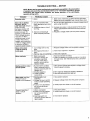
trouble shooting
WARNING: FOR YOUR OWN SAFETY, TURN SWITCH "OFF" AND REMOVE PLUG FROM
POWER SOURCE OUTLET BEFORE TROUBLE SHOOTING YOUR JOINTERPLANER.
TROUBLE
TROUBLE
1. Defective On-Off switch.
Defective switch cord.
Defective switch box
receptacle.
2. Motor protector open (only
if your motor is equipped
wi:th an ovedoad protector),
:
....
CHART
PROBABLE CAUSE
-
SHOOTING
:
REMEDY
1. Replace defective parts before using machine
again.
2, Consult Sears Service. Any attempt to repair this motor
may create a HAZARD unless repair is done by a
qualified service technician. Repair service ls available
table after passing over , below surface of outfeed table.
Ripples on planed
surface,
Planed surface not
straight.
I
InrOad table loose,
,
....
Cutter guard does not
function properly,
....
"
_ ....
1. Re-adjust btades, see Maintenance
Infeed table out of adjustment.
Re-adjust infeed table, see Getting
Planer section.
Blades set too h gh above
outfeed table.
Reset blades, see Maintenance section.
,
Excessive gouging at
end of cut.
90 ° and 45 ° cuts
inaccurate,
1, One blade set higher than
other.
2. Feeding wood too fast.
section.
2. Feed wood slower.
1. Fence stops not adjusted
1.
properly.
2. Fence slide bracket not
2.
•
even with table.
l l Dovetail spacer requires
1.
adjustment,
i
2. Female dovetail loose from!
2.
To Know your Jointer'
Re-adjust fence stops, see Getting To Know your
Jointer Planer section+
Re-adjust slide bracket, see Getting To Know your
Jointer Planer section.
Tighten screw, key lO, see fig, 3 Parts List.
Tighten
screws, key 17, see fig. 3, Parts List.
t
table.
:
i
...........
1. Return spring brokeni or
1 Replace spring immediately. See Maintenance
spring has been weakened_ :
:
_ 2. improper assembly of
2. See Maintenance section.
I
spring or guard mounting.
section.
TROUBLE
SHOOTING
-- MOTOR
.......
NOTE: Motors used on wood-working tools are particularly susceptible to the accumulation
of Sawdust and wood chips and should be blown out or "vacuumed" frequentiy to prevent =
interference with normal motor ventilation and proper operation of the centrifugallyoperated starting switch.
,'
TROUBLE
PROBABLE
CAUSE
REMEDY
Excessive noise.
1, Motor,
1, Have motor checked by qualified service technician.
Repair service is available at your nearest Sears store.
Motor fails to develop
full power, NOTE:
LOW VOLTAGE: (Power
output of motor
decreases rapidly with
decrease in voffage at
motor terminals. For
example, a reduction of
10% in voltage causes a
reduction of 19% in
maximum power output
of which the motor is
capable, and a reduction
of 20% in voltage causes
a reduction of 36% in
maximum power output.)
1. Circuit overloaded with
lights, appliances and other
motors.
2r Undersize wires or circuit
too long.
t. Do not use Other appliances
when using the jointer.
Motor starts slowly
or fails to come up
ito full speed,
!. Low voltage will not trip
relay,
2. Windings burned outor
open.
3. Starting relay not operating.
1. Request voltage check from the power company.
!. Motor overloaded.
2. Improper cooling. (Air
circulation restricted
through motor due to
sawdust, accumulating
inside of motor).
1. Burned switch contacts
(due to extended hold-in
periods caused by low line
voltage, etc.).
2. Shorted capacitor.
3. Loose =or broken
connections.
1. Feed work slower into blade.
2. Clean out sawdust to provide normal air circulation
through motor. See "Maintenance and Lubrication"
section.
1. Starting switch not
operating.
2. Voltage too tow to permit:
motor to reach operating
speed!
3. Fuses or circuit breakers
do not have sufficient
capacity.
1. Motor overloaded.
2. Fuses or circuit breakers
do not have sufficient
capacity.
3, Startring switch not
operating (motor does not
reach speed).
1. Have switch replaced.
Motor overheats.
Starting switch in motor
wilt not operate.
Motor stalls (resulting
in blown fuses or
tripped circuit breakers),
Frequent opening of
fuses or circuit
breakers.
3. General overloading of
power company facilities.
or motors on same circuit
2. Increase wire sizes, or reduce length of wiring. See
"Motor Specifications and Electrical Requirements"
section.
3. Request a voltage check from the power company.
2. Have motor repaired or replaced.
3. Have relay replaced.
1. Have switch replaced and request a voltage check
from the power company.
2. Have capacitor tested and replace if defective.
3. Have wiring checked and repaired.
2. Request voltage check from the power company.
3. Install proper size fuses or circuit breakers.
1. Feed work slower.
2. install proper size fuses or circuit
breakers.
3. Have switch replaced.
2
repair paris
\
Li.
26
-n
"o
d
0
o
-0
co
nt
.-_"
_
0
•_
_
0._-
_
l'_?
x
O-
oE
_
_.oxo
._r
--
^_
_
O_
Z_
_ 0_
eo
o
0
E
o_
mm0
"r nO 00 _ _0 _0 m 0
c
+
w
0
o
E
tG
0 z
_
0
z
o_
o_
_
o
_>. oO
____o__
2:."i
0
wE
Z
"J
I_
_z_,.
m
--
_
_
Z<
h-
•
"0
"-
0
0
,-
0
"r
o
F_"
z
Eb5
+
o
_r_
.......
0
_00_
_o!_
r_
_
0
-
-
_ ,
_
_.m
0
-- m
0
_
00_
x ×
0
•
0
27
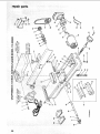
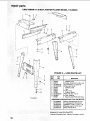
repair parts
CRAFTSMAN
6-1/8
INCH JOINTER-PLANER
MODEL
113.206933
5
/
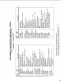
FIGURE
2 -- LEGS PARTS
Part
No.
Key
No.
LiST
Description
ii
1
67033
60314
STD551225
STD541025
67032
62614
62204
67034
STD541250
803835
67035
2
3
4
5
6
7
8
9
10
FIGURE
2
HARDWARE
--
FOR MOUNTING
STD532507
STD551231
STD551031
STD523120
:
28
Stiffener, End
• Screw, Truss Hd. 1/4-20 x 5/8
e*Lockwasher, 1/4 External
e'Nut, Hex 1/4-20
Stiffener, Side
Leg
• Clip, Cord
Support, Motor
e'Nut, Hex Hd. 1/2-13
D Foot, Leveling
Bag of Loose Parts (Not Iltus.)
TOOL AND MOTOR
e'Bolt, Carriage 5/16-18 x 3/4
e*Lockwasher, 5/16 External
s'Washer, 1!/32 x 11/16 x 1/t6
t'Screw, Hex Hd= 5/16-16 x 2
e'Nut, Hex 5116-!8
oSupptied
in Loose Parts Bag 67035
*Standard
Hardware
Item - May be Purchased Locally.
CRAFTSMAN
1
6-1/8
INCH JOINTER-PLANER
MODEL
113.206933
\
21
/
23
\
\
\
\
2o
\
2
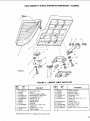
FIGURE
22
3
11
FIGURE
Key
No.
Part
No.
1
2
3
4
5
6
7
8
9
t0
STD561210
67015
67014
STD511107
STD5512t0
STD551010
38779
67011
67012
STD522505
11
12
STD55tO25
21812
Hardware
i
TABLE PARTS
Key
No.
Description
nl ,,i,n i ,n
*Standard
3 -- INFEED
Part
No.
LIST
Description
inl
*Pin, Cotter, 1/8x 1
Guard
Tabfe (with Name Plate)
*Screw Pan Hd. 10-32 x 7/8
*Lockwasher No. 10
*Washer, No. 10
Spring. Guard
Plate Support
Bushing
*Screw, Cap, 1/4-20 x !/2,
Hex Hd.
*Washer, Plain, 17/64
Plate, Tension=
Item -- May Be Purchased
13
14
15
16
17
18
21422
21219
21218
STD551131
i21635
STD523112
19
20
21
22
23
STD551031
21204
STD54!025
STD551125
STD5225t0
Spacer, Dovetail
Dovetail, Male
Dovetail, Female
* Lockwasher, 5/16
Screw, Spl.
*Screw, Cap, 5/16-18 x t_1/4
Hex Hd.
*Washer, 5/I6
Linkage Assembly
*Nut, Hex,, 1/4-20
"Lockwasher, 1/4
*Screw, Cap, 1/4-20 x 1, Hex Hd.
Locally.
29
CRAFTSMAN
5
6
6-1/8
INCH JOINTER-PLANER
MODEL
113.206933
7
9
/
/
17
10
\
/
16
11
\
12
15
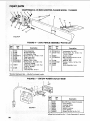
FIGURE 4
FIGURE
Key
No. I
Part
No.
4 -- 21013 FENCE
ASSEMBLY
Key
No.
Description
PARTS
Part
No.
Description
i
,,, ,,,
21013
1
21440
2
21430
STD522512
21232
Plunger Assembly
i
21736
STD551010
7
STD510802
r
8
102817
9
i
21229
I
*Standard
:,,
.Pin Assembly, Stop
Screw, Hex Hd. 1/4-20 x !-t/4
Plate, Fence End
Scale, Fence Tilt
*Washer, Ptain, 13/64
*Screw, Mach., No. 8-32 x 1/4,
Bind Hd., Slotted
Screw, Se[, 1/4-20 x 1/2", Full
Dog Pt., Slotted
, Body, Fence
nc KeyNo's
10&11
.
LIST
10
11
STD551210
STD511102
12
13
67009
STD533725
14
15
16
17
21738
STD551037
47624
62331
*Lockwasher, Ext. #10
*Screw, Mach,, No. 10-32 x t/4,
Pn Hd., Slotted
Guard, Cutter
"Bolt, Carriage, 3/8-t6 x 2-1/2
Round Head
Retainer, Bolt
*Washer, 13/32 x 13/16 x !/16
Spacer
Knob Assembly, Lock
•
Hardware Item -- May BePurchased
FIGURE
Locally.
5 -- ON/OFF
POWER
OUTLET
60381
6
Key
No.
FIGURE 5
-1
2
3
4
5
6
Part
No.
60381
60375
60380
60256
60374
60376
cOn/Off Power Outlet Complete
Cord, Molded
Housing, Switch
Key, Switch
' Switch, Locking
Cover Switch
448007
i Screw, PanHd,
eDoes Not Include
3O
Description
No.6x3/4
Key No. 3 Order Separately
If required.
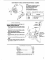
CRAFTSMAN
6-1/8 iNCH JOINTER-PLANER
MODEL
113.206933
NOTE:
ANY ATTEMPT TO REPAIR THIS MOTOR
MAY CREATE A HAZARD UNLESS
REPAIR iS DONE BY QUALIFIED
SERVICE TECHNICIAN.
REPAIR SERVICE IS AVAILABLE
AT YOUR NEAREST SEARS STORE,
FIGURE
Key
No.
........ •
...........................................................
6 -- 67094 MOTOR
Part
No.
1
60306
2
3
64088
64258
PARTS
LIST
Description
Screw, 8_32 x 3/8, Thread
Cutting, Slotted, Serrated
Cover, Terminal
Cord with Plug
Hd.
, ,,,i,i,,
TERMINAL
GREEN
MOTOR CONNECTIONS
WARNING: FOR YOUR OWN SAFETY, NEVER CONNECT
PLUG TO POWER SOURCE
OUTLET
UNTIL ALL
ASSEMBLY STEPS ARE COMPLETED.
INTERNAL
LOCKWASHER
1. Open motor connector box cover located on left end
of motor (viewed from rear of saw) using a flat b_ade
screwdriver,
2. Remove GREEN SCREW and Iockwasher and insert
screw through round metal terminal on the end of the
GREEN wire of power cord with Iockwasher between
terminal and motor frame. (See [llus_)
3. Reinsert GREEN SCREW in the threaded hole, Tighten
securely.
_TO
4. Insert terminal end of WHITE wire on spade terminal
marked T4 on the motor, Push terminal firmly until
seated.
GREEN
GREEN
WtRE
SCREW
STRAIN RELIEF
)VE
WHITE WIRE TO
TERMINAL T4
5. Insert terminal end of BLACK wire on spade termina_
marked T1 on the motor. Push terminal firmly until
seated.
6. Close motor connector box being sure that power
cord is seated in the largest strain relief groove, and
tighten box cover screws.
IIIHI,,
_
RECOMMENDED
i
H ...........................
ii
ACCESSORIES
ITEM
Steel Legs .................................
FloOr Stand ..............................
Cutter Blades ..............................
Power Too! Know-how Handbooks
Radial Saw ..............................
Table Saw .................................
Knife Setting Gauge ........................
Chip Collector ............................
CAT. NO.
9-22245
9-22216
9-2293
9-291;
9o2918
9-2647
9-29977
The above recommended accessories are current
were available at the time this manual was printed_
and
31
SL _,AIR,,
6-1/8 iNCH JOINTER-PLANER
SERVICE
MODEL NO.
11 3.206933
Now that you have purchased
your jointer-planer,
should a
need ever exist for repair parts or service, simply contact
any Sears Service Center and most Sears, Roebuck and Co,
stores. Be sure to provide all pertinent
facts when you call
or visit.
JOINTERiPLANER
WITH
LEGS AND MOTOR
The model number of your 6-1/8 inch jointer-planer
found on a plate attached to your base.
HOW TO ORDER
REPAIR PARTS
WHEN ORDERING
REPAIR
FOLLOWING
INFORMATION:
PARTS,
ALWAYS
wil! be
GIVE THE
PART NUMBER
PART DESCRIPTION
MODEL NUMBER
113.206933
NAME OF ITEM
6-1/8 INCH JOtNTER-PLANER
All parts listed may be ordered
from any Sears Service
Center and most Sears stores. If the parts you need are not
stocked locally, your order wilt be electronically
transmitted
to a Sears Repair Parts Distribution
Center for handling.
Sold
Part No. 67096
by SEARS,
ROEBUCK
AND
CO.,
Form No. SP4939-1
Chicago,
IL. 60684
U.S.A.
Printed in U.S.A. 11/