1
OWNER'S
MANUAL
®
3.8 Horsepower
9 anch
EDGER/TRIMMER
MODEL NO.
536.797470
Caution:
Read and follow all Safety
Rules and Operating
instructions before first use
of this product.
Sears, Roebuck and Co., Hoffman Estates 60179 U.S.A.
339690 3/04t96
Table of Contents
Warranty
Safety Rules
Contents of Shipping Carton
Assembly
Operation
Maintenance
2
2
2-3
4
5-7
7-11
11-12
Service and Adjustments
Storage
Troubleshooting
Spanish (EspaSol)
Edger Repair Parts
Engine Repair Parts
Parts OrdertnglService
13.14
14-15
t5
16-30
31-35
36-39
Back Cover
LIMITED ONE-YEAR WARRANTY
ON CRAFTSMAN
EDGER/TRIMMER
For one year from the date of purchase, when thisCraftsman Edger/Trimmer is maintained, lubricated, and tuned up according to the operating and maintenance instructions in the owner's manual, Sears will repair, free of charge, any defect in material or
workmanship._
If this Craftsman Edger/Trimmer is used for commercial or rental purposes, this warranty applies for only 90 days from the date of purchase_
This warranty does not cover the following:
. Expendable items which become worn during normal use, such as spark plugs, etc.
* Repairs necessary because of operator abuse or negligence, including bent crank
shafts and the failure to maintain the equipment according to the instructionscontained in the owner's manual
WARRANTY SERVICE IS AVAILABLE BY RETURNING THE CRAFTSMAN EDGER/
TRIMMER TO THE NEAREST SEARS SERVICE CENTER/DEPARTMENT IN THE
UNITED STATES. THIS WARRANTY APPLIES ONLY WHILE THIS PRODUCT IS IN
USE IN THE UNITED STATES.
This warranty gives you specific legal rights, and you may also have other rightswhich
may vary from state to state.
Sears, Roebuck and Co,, D817WA, Hoffman Estates, |L 60179
_k
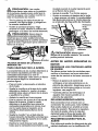
Look for this symbol to potnt out Important safety precautions, It means-°ATTENTION!!! Become alertif! Your safety is Involved.
CAUTION: Always disconnect spark
plug wire.and place wire where it cannot
contact spark plug to prevent accidental
starting when setting-up, transporting,
adjusting or making repairs,
wearing adequate outer garments, Wear
footwear that will improve footing on
slippery surfaces.
• Keep the area of operation clear of aft
persons, particularly small children and
pets..
• Thoroughly inspect the area where the
edger/trimmer is to be used and remove
all foreign objects,
FUEL SAFETY
• Handle fuel with care; it is highlyflammableo
• Use an approved container.
• Check fuel supply before each use,
allowing space for expansion as the heat
of the engine and/or sun can cause fuel to
expand,
• Fill fue! tank outdoors with extreme care.
Never fill fuel tank indoors. Replace fuel
IMPORTANT: Safety standards require
operator presence controls to minimize the
risk of injury. Your Edger/Trimmer is
equipped with such controls, Do not attempt
to defeat the function of the operator
presence control under any circumstances,.
BEFORE USE
• Read the owner's manual carefully., Be
thoroughly familiar with the controls and
the proper use of the edgerttrimmer_
Know how to stop the edger/trimmer and
disengage the controls quickty_
, Do not operate the edgerltrimmer without
2
tank cap securely and w_pe up spilled
fuel.
• Never remove the fuel tank cap or add
fuel to a running or hot engine°
• Never store fuel or edger/trimmer with
fuel in the tank inside a building where
fumes may reach an open flame.
OPERATING SAFETY
• Never allow children or young teenagers
to operate the edger/trimmer, Keep them
away while it is operating, Never allow
adults to operate the edger/trimmer
without proper instruction,
. Do not operate this machine if you are
taking drugs or other medication which
can cause drowsiness or affect your
ability to operate this machine.
• Do not use this machine if you are
mentally or physically unable to operate
this machine safely,
'
'
. Always wear safety glasses, or eye
Shields during'opei'ati0n .or while performing an adjustment or repair to protect
your eyes from foreign objects that may
be thrown from the adgedtrimmer.
• Do not put hands or feet near Or under
rotating parts.
• Exercise extreme caution when operating
on or crossing gravel drives, walks, or
roads. Stay alert for hidden hazards or
traffic.
• Exercise caution to avoid slipping or
falling..
• Never operate the edger/trimmer without
proper guards, plates, or other safety
protective devices in place,
- Never operate the edger/trimmer at high
transport speeds on slippery surfaces.
Look behind and use care when backing
• Never allow bystanders near the edger!
trimmer.
• Keep children and pets away while
operating.
• Never operate the edger/trimmer wilhout
good visibility or light.
, Do not run the engine indoors_The
exhaust fumes are dangerous, containing
CARBON MONOXIDE, an ODORLESS
and DEADLY GAS.
.'
• Take all possible precautions when
leaving the edger/trimmer unattended°
Stop the engine°
. Do not overload the edger/trimmer
capacity by attempting to edge too deep
at too fast a rate.
SAFE STORAGE
Always refer to the owner's manual
instructionsfor important details if the
edger/trimmer is to be stored for an
extended period..
• Never store the edger/trimmer with fue_ in
the fuel tank inside a building where
ignition sources are present such as
water and space heaters, clothes dryers,
and the likeoAllow the engine to cool
before storing in any enclosure.
• Keep the edger/trimmer in safe working
condition. Check all fasteners at frequent
intervals for proper tightness.
REPAIR!ADJUSTMENTS SAFETY
. After strikinga foreign object, stop the
engine (motor). Remove the wire from the
spark plug, and keep the wire away from
the plug to prevent accidental starting.
Thoroughly inspect the edger/trimmer for
any damage, and repair the damage
before restarting and operating it,,
,; If edger_rimmer shouldstart to vibrate
abnormally, stop engine (motor) and
check inlmediatelyfor the cause.
Vibration is generally a warning of
trouble,
• Stop the blade whenever you leave the
.operating position. Also, disconnect the
spark plug wire before unclogging the
blades and when making any repairs,
adjustments, or inspections.
• When cleaning, repairing, or inspecting,
shut off the engine and make certain all
moving parts have stopped.
• Never attempt to make any adjustments
while the engine is running except when
specifically recommended by the manufacturer..
WARNING: The engine exhaust
from this product contains chemicals
known to the State of California to cause
cancer, birth defects or other reproductive
harm,.
WARNING: This unit is equipped
with an internal combustion engine and
should not be used on or near any unimproved forest-covered, brush-covered or
grass-covered land unless the engine's exhaust system is equipped with a spark arrester meeting applicable local or state laws
(if any). if a spark arrester is used, it should
be maintained in effective working order by
the operator,
In the state of California the spark arresler
is required by law (Section 4442 of the California Public Resources Code). Other
states may have similar laws. Federal laws
apply
on federal lands_ A spark arrestor/
Sears Authorized Service Center (See REPAIR PARTS section in this manual).
muffler is avaitabIe through your nearest
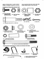
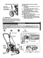
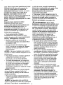
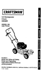
Contents of Parts Bag (actual size)
(4) - Hex Head Wide
Flange Screws
5/16-18x 5/8 Inch
(8) - Hex Head Nuts
5/16-18
(I) - Spacer _70 Inch
(left rear wheel
assembly)
(t) - Hex Head Jam
nut 3t8_16
jlllIll Itll
(2 i - Hair Pins
1 - Cotter Pin
11) - Shoulder Bolt 3/8_16 x 1AQQ inch
@
(1) - 5/16-18 Hex Head
Wide Flange Locknut
(1) - 112 x 3t4 Inch
Flatwasher(right rear
wheel assembly)
(2) - 11t32x11/16 inch
Flatwashere (front wheel
assembly)
©i ...... 1
(4)- Hex Head Screws
5116-18x 1-114 Inch
(I) - Io39 Inch long Spacer
(front wheel assembly)
(1) - 5f16_18 x 3_00 Inch Hex Head Screw
Parts packed separately In carton (not shown full size)
(3) - Wheels
(1) - Lower Handle
(1) -Control
1 - Container SAE30 oit
Rod
(1) - Upper Handle
Assembly
1 - Owner's Manual (not shown)
2 - Parts Bags (not shown)
4
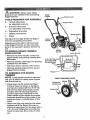
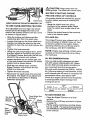
_'/V_ CAUTION: Always wear safety
glasses or eye shields while assembling
Edger!Trimmer,
Upper
Handle
Lever
TOOLS REQUIRED FOR ASSEMBLY
2 - 1/2 inch Wrenches
(or adjustable wrench)
2 - 9/16 inch Wrenches
(or adjustable wrenches)
Rod
2 - Adjustable Wrenches
1 - Regular Screwdriver
1- Pliers
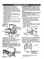
The figure to the right shows the Edger/
Trimmer completely assembled,
References to the right or left hand side
of the Edger/Trimmer are from the viewpoint of the operator's position behind the
unit,,
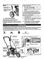
TO REMOVE EDGER/'[RIMMER
FROM CARTON
. Remove the lower handle, control rod,
upper handle and packing material from
the carton.
• Remove wheels, parts bags and packing
material from the carton.
• Cut down all four corners of the carton,
• Remove packing material from around
Edger/Trimmer blade.
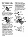
TO ASSEMBLE THE EDGER/
TRIMMER
NOTE: Lower handle shouldbe attached
first as it is difficult to attach lower handle
with the wheeis on.
- Place lower handle inside the Edger/
Trimmer frame as shown in top figure
and secure in place with four 5/1 6-18x
5/8 inch hex head wide flange screws
and four 5/1 6-18 hex head Iocknuts
found in parts bag. Hold back on the
lower handle as you tighten the screws,
Locknuts should be on the inside of the
frame as shown in middle figure of this
page°
• Attach the right rear wheel to the wheel
support rod of the Edger/Trimmer as
shown in lower figure on this page with a
1/2 x 3/4 inch flatwasher and cotter pin
found tn parts bag, Bend ends of cotter
pin,,
Handle
de
Handle
5116-18X 5/8 inch(_
Lower Handle
!
/
5116-18)-_
-tHex Head !
,
Frame/
VIEW FROM RIGHT SIDE
112x3/4 '
Pit
Flatwasher
Cotter _
_
Wheel _[
_
'
, Attach the left rear wheel tothe Edger!
Trimmer shown in figure below with a
3/8-16 x 1.40 inch shoulder bott,spacer
and 3/8-16 hex head jam nut found in
parts bag.
ViEW FROM INSIDE LEFT REARWHEEL
Spacer
(_70inchtong)
ShoulderBolt
i
Move the clutch lever to rearmost
NEUTRAL position and latch in,
If it is difficult to get the clutch lever into
NEUTRAL, it may be necessary to loosen
the four screws and nuts holdingthe
lower handles to the frame as shown in
first figure on page 7, Pry up (forward) on
the handles only enough to allow the
clutch lever to freely enter the NEUTRAL
position. Re-tighten nuts and screws.
When the clutch lever is in NEUTRAL the
quill support arm should be close to the
spacer and screw behind it as shown
below.
318-16
Jam Nut
position)
_.._. lutch
r
Lever
Attach the front wheel to the Edger/
Trimmer shown in figure be!ow with a
5/t6-t8 x 3.00 inch hex head screw, two
11132x 11/16 inch flatwashers, one
spacer and a 5ti6-18 hex head wide
flange locknut found in parts bag,
trol
Rod
VIEW FROM FRONT
Locknuts
5/16-18 Wide
Range Locknut
x1-1/4
Hex Head
Screw
It132xl 1/16
_atwasher
11t32xl 11t6Inch
Hex H
Screw
(
5/16-18x3inches
Handle
Long)
• Place the upper handle on the lower
handle zs shown in next figure and at[gn
upper handle holes in lower handle, and
secure in place with four 5/16-18 x 1-114
inch hex head screws and four 5/16_18
hex head locknutsfound in parts bag.
Locknuts should be to the inside of the
two handles as shown,
• The clutch lever is located on the left
hand side of upper handle when properly
Installed, Insert one end of the control rod
from left to right through the hole in the
clutch lever and attach with a hair pin
found in parts bags, See next figure,
, Place the clutch lever in the first depth
selection and insert the other end of the
control rod through the hole in the quill
support arm. Attach with hairpin found in
parts bag_
Quill
cer
Arm
VIEW FROM RIGHT SIDE OF UNIT
RightSide
Lower
LowerHandle
Mounting
er CHECKLIST
Before you operate and enjoy your new
Edger/Trimmer, we wish to assure that you
receive the best performance and satisfaction from this quality pmducto
PLEASE REVIEW THE FOLLOWING
CHECKLIST:
_f Al! assembly instructions have been
comp_eteoo
,/" No remaining loose parts in carton_
,/" All fasteners have been properly inn
stalled and tightened.,
While learning how to use your Edger/
rimmer, pay extra attention to the following important items;
_'€" Engine oil is at proper level
=Z_f Fuel tank is filled with fresh, clean,
regular UnIeaded gasoline_
JJ Become familiar with all controls-their
location and function. Operate controls
before starting engine.
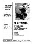
KNOW YOUR EDGER/TRIMMER
READ THIS OWNER'S MANUAL AND SAFETY RULES BEFORE OPERATING YOUR
EDGER/TRIMMER. Compare the illustrationswith your EDGERKRIMMER to familiarize
yourself with the Ibcation of variouscontrols and adjustments°Save this manual for future
reference.
Fast
Stow
Stop
Primer Button
Con_olRod
ThrotUe
VIEW OF BLADE AREA
Rear
1
Throttle Control - Used to control the engine speed.
Primer Button - injectsfuel directly into the
carburetor manifold for faster starts.
Starter Handle - The engine on this Edger/
Trimmer is equipped with an easy pull recoil
starter°
Clutch Lever - Used to start and stop the
blade and control the depth of cut.
Blade Guard - Used to prevent stones or
other material from being thrown at the operatoro
secondsbetween each push.
. Do notuse primerbuttonto restarta
warmengineaftera shortshutdown.
TO USE THE CLUTCH LEVER
• Start the engine and move the clutch
lever forward or down to engage the
cutting blade.
- Select the edging depth you need.
There are 5 selections up to 2-3/4
inchesdeep_
IMPORTANT: ff very deep edging is
required, we recommend that a shallow cut be made first, then cuts at
greater depths until the desired depth
is obtained_
TO USE THE INDEX LEVER
Index Lever - Permits adjustment from the
edging (vertica})positionto trimming (horizontal) position, To change position, puUthe
index lever and rotate the quillassembly to
the desired angle or position.
Adjustable Rear Wheel - Right rear wheel
is adjustable to level Edger/Trimmer when
edging along a curb(curb-hopping).
Adjustable Front Wheel - Front wheel is
adjustable from side-to-side for balance..
Also, can be adjusted down for curb-hopping_
(TRIMMING OPERATION)
• Stop engine and disconnect the spark
plug wire from the spark plug_
- Loosen the knob shown Jnfigure below
on the front wheel arm and slide the
wheel all the way to the right side°
• Tighten the knob securely.
Z_
CAUTION: The front wheel must be
in the extreme right position to prevent the
blade from striking wheel while in trimming
position_
HOW TO USE YOUR EDGER
Z_
WARNING: The operation of this
Edger/Trimmer can result in foreign objects
being thrown into the eyes, which can cause
severe eye damage. Always wear safety
glasses or eye shields while operating the
Edger/Trimmer.
We recommend standard safety glasses or
Wide Vision Safety Mask for over your
glasses.
TO STOP EDGER/TRIMMER
. To stop the engine, make sure the clutch
lever is all the way back or up and move
the throttle controi lever to the STOP
ositon,
CAUTION: Never leave the Edger/
Trimmer unattended while the engine is
running, Always disengage the cutting blade
and stop the engine,
• Pull the index lever out of its notch as
shown below and position it in the
notch marked 90 =. See figure on page 9.
• Reconnect the spark plug wire and
start the engine, Move the clutch
lever to the destred tdmming height.
,/_
CAUTION: Never leave the Edger/
Trimmer unattended while the engine is
running. Always disengage the cutting
blade and stop the engine,
7'0 USE THROTTLE CONTROL
• Run at fulI engine speed during normal
use.
• Push throttlecontrol lever up to increase
speed; down to decrease speed.
TO USE PRIMER BUTTON
. Push primer button five times See page 7
figure for location_ Wait about two
8
CAUTION: Keep away from the
rotating blade, The blade can cause injury
BEFORE
STARTING
ENGINE
PRE-USE CHECK OF CONTROLS
INDEX LEVERIN THE NOTCH MARKED "90"
TO USE CURB-HOPPING FEATURE
The adjustable front and right rear wheel
feature permit the Edgar/Trimmer to be
used on an uneven surface such as a curb
as shown in figure below,
. Stop the engine and disconnect the
spark plug wire from the spark plug,
• Loosen the knob on the front wheel arm
bracket and slide the wheel to the best
position to clear the curb and balance the
unit.
• Tighten the knob securely,
. Using the curb height adjust lever, lower
the front wheel to a position that places
the Edger/Trimmer level with the left rear
wheel on the uneven curb surface,
. Loosen tee knob on the inside rightrear
of the main frame that secures the wheel
support rod as shown below.,
• Slide the rear wheel down until the
Edger/Trimmer is level when the left
wheel is on the curb.
. Tighten the knob securely,
• Reconnect the spark plug wire and start
the engine. The depth of cut adjustment
is the same as described in Edging
Operation paragraph,
Ati controls shou!d be checked for proper
function before servicing or starting the
engine.,
° Move the clutch lever into all six
positions in the selector plate, Make
sure the clutch lever snaps into all six
holes,
• Return the clutch lever to the rearmost
hole in the selector plate°
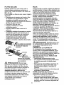
FILL/ADD OIL:
This Edger/Trimmer was shipped with a 20
ounce container of SAE30 motor oil This
oit must be added to the engine before
operating, Remove the oil fiI_cap and fill
the crankcase,, DO NOT OVERFILL,
NOTE: Engine may already contain some
residualoil Check frequently when filling
the crankcase.
OIL RECOMMENDATIONS
Only use highquality detergent oil rated
with API service classificationSG, Select
the oil's SAE viscosity grade according to
your expected operating temperature
Although multi*viscosity oils (5W30, t0W30,
etc_) improve starting in cold weather, these
multi-viscosity oiJswili result in increased oil
consumption when used above 32°F.
Check your engine oil level more frequently
to avoid possible engine damage from
runninglow on oil,
j
Colder <€
-- )>Warmer
((
SAE30
TO ADD ENGINE OIL
Front Wheel Arm
Tee Knob
(Behind..
Wheel)_,
Rear
Front
Support
Rod
Adjust Lever
j
_))
5W30
* Ptace the Edger/Trimmer on a level
surface.
• Remove the oil fill cap as shown in figure
on page 10,
. Fill the engine crankcase, pouring sEowiy,
Do not overfill, For approximate capacity
see PRODUCT SPECIFICATIONS chart
in this manual°
o
v
Reinstall the oil fill cap and tighten
securely
Check oil before each use Add if
needed
Change oil after the first2 operating
hours and every 25 operating hours
thereafter.
Cap
Oil Fill Cap
WARNING: Experience indicates
that alcohol blended fuels called gasohol or
using methanol can attract moisture which
leads to separation and formation Ofacids
during storage. Acidic gas can damage the
fuel system of _n engine while instorage
To avoid engine problems; the fuel system
should be emptied before storage of 30
days or longer. Drain fuel tank, start engine
and let _trun untilfuel lines and carburetor
are empty Use fresh fuel next season. See
Storage Instructions for additional information. Never use engine or carburetor
cleaner products in the fuel tank or permanent damage may occur°
TO START THE ENGINE
Before starting the engine, be sure you
have read and understood all the instructions on the preceding pages The Edger/
Trimmer is equipped with a recoil starter.
The operation of the engine is controlled by
the throttle control lever
• Pull the clutch lever all the way back or
up to the rearmost hole to raise and
disengage the bladeo
• Move the throttle control lever, see figure
on page 7 to the FAST position
• Push primer button five times, see figure
on page 7. Wait about two seconds
between each push
FILL GAS
Fill the fue! tank with clean, fresh, unleaded
grade automotive gasoline. Be sure that
the container you pour the gasoline from is
clean and free from dust or other foreign
particles° Never use gasoline that may be
stale from long periods of storage in the
container.
L_ CAUTION: Never fillthe gas tank
while the engine is runningor hot
Immediately wipe off any spilledgasoline
before attempting to start the engine,,
/_ CAUTION: Gasoline is flammable
and caution must be used when handlingor
storing it. Do not fill fuel tank while Edger/
Trimmer is running, hot, or when in an
enclosed area, Keep away from open
flame, electrical spark, and do not smoke
while filling the fuel tank Never fillfuel tank
completely; but fillthe tank to within 1/4-1/2
inch from the top to provide space for
expansion of fuel Always fill fuel tank
outdoors and use a funnel or spout to
prevent spilling. Make sure to wipe up any
spilled fuel before starting the engine Store
gasoline in a clean, approved container,
and keep the cap in place on the container
Keep gasoline in a cool, well ventilated
place; never in the house Never buy more
than a 30 day supply of gasoline to assure
volatility_ Gasoline is intended to be used as
a fuel for internal combustion engines
therefore, do not use gasoline for any other
purpose° Since many children like the smell
of gasoline, keep it out of their reach
because the fumes are dangerous to inhale,
as wel! as being explosive°
NOTE: Do not use primer button to
restart a warm engine after a short
shutdown
• To start engine, grasp the engine starter
handle firmly with your right hand°
• Hold the edger handle firmly with your
left hand
• Pull up sharply on the recoil starter
handle DO NOT allow the starter rope to
snap back, let it rewind slowly while
holding the starter handle If engine fails
to start after three pulls, push primer
button two times and pull starter rope
again.
• When the engine starts Push throttle
control lever up to increase speed; down
to decrease speed Run at full engine
speed during normal use°
NOTE: The cutting blade speed is
controlled by the engine speed_To
reduce the cutting blade speed, push
down on the throttle control lever To
increase the blade speed, push the
to
throttle control lever up
• tf very deep edging is required, we
recommend that a shallow cut be made
first,then cuts at greater depth until the
desired depth is obtalned.
• Uniform edging can be performed when
the blade guide rides on and against the
surface whtch you are edging.
• Edging can be customized by varying the
number of passes and by the distance
your blade is from the surface you are
edging°
, To stop the engine, make sure the clutch
lever is al! the way back or up and move
the+throttle control lever to the STOP
position.
CAUTION: Never run the engine
indoorsor in a poorly ventilated area°
Engine exhaust contains carbon monoxide,
an odorless and deadly gas,,Keep hands,
feet, hair and loose clothing away from any
moving parts on the engine or edger/
trimmer. Avotd the muffler and surrounding
areas° Temperatures may exceed 150° F.
EDGING
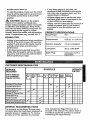
PRODUCT
SPECIFICATIONS
Horse Power:
3°8
DisPlacement:
9.52 cu. in. (156 cc)
TIPS
• Edging is best p+erformedwhen conditions
are dry. If the soil Jsto wet, dirt becomes
packed in and around the blade causing
premature belt wear and decreased
performance°
• tf did does become packed around the
blade, stop the engine, remove the spark
plug wire, and remove the packed debris
before continuingto edge°
CUSTOMER
2_0 qL (unleaded)
Lubrication:
20 oz. SAE_30W
Spark Piug:
Champion CJ-8 or
Equivalent
RESPONSIBILITIES
_
RECORDS
Fill In dates as
you complete
regularservice
After "_Before'Frs_,
First
2
Hours
Each
use
quontiy
"EVOW'Evory
Every
5
10
25
'=Hours Hours Hours
Lubricate aU Pivot Points
V'
LubricateWheelAxies
CheckEngineoii Levei
ChangeEngine
0t1
Replace AirCleaner
Filter
Begin
kach
Season
v,
Bslora
Storage
,I
I
,I
I
I
v"
..... _
v"
__i
,I
I
Chock
Sp_. Ptug
Check Drive Belt
v"
I
i !!ii!
Tighten All Screws and Nuts
CheckBladeWeas/Damsge
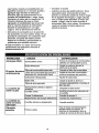
GENERAL
i
RECOMMENDATIONS
must maintain the Edger/Trimmer as instructed in this manual. The above chart is
provided to assist the operator in propedy
maintaining the edger/trimmer
The warranty on this Edger/Trimmer does
notcover items that have been subjected to
operatorabuse or negligence, To receive
full value from the warranty, the operator
I1
NO INFO
NO
INFO
ling
@
@
o
Blade
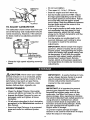
TO ADJUST CARBURETOR
The carburetor shown below has been preset at the factory and readjustmentshould
not be necessary° However, if the carburetor does need to be adjusted, proceed as
follows:
Carburetor
Do not over4ighten,
Then open it 1-1/4 to 1-1/2 turns.
Start the engine and let it warm up.
Set the throttlecontrol to FAST, Adjust
the high speed adjusting screw In until
the engine speed or sound alters. Adjust
the screw out until the engine speed
sound alters, Note the difference between
the two limits and set the screw in the
middle of the range,
ff the engine tends to stall under load or
not accelerate from low speed to high
speed properly, adjust the h_gh speed
screw out fn 1/8 turn increments untit the
problem is resolved.
Let the engine run undisturbedfor 30
seconds between each setting to allow
the engine to react to the previous
adjustments.
IMPORTANT: Never tamper the engine
governor, which is factory set for proper
engine speed. Overspeeding the engine
above the factory high speed setting can
be dangerous, if you think the enginegoverned high speed needs adjusting,
contact your nearest Sears Seryice
Center, which as the proper equipment
and experience to make any necessary
adjustments.
HighSpeed
Screw
only)
• Close the high speed adjusting screw by
hand.
Z_ CAUTION: Never storeyouredger!
trimmerindoorsor inan enclosed,poorly
ventilatedarea ifgasolineremainsin the
tankfumesmay reachanopenflame,
sparkor p_Iotlightfrom a furnace,water
heater,clothesdryer,cigarette,etc.
IMPORTANT: A yearly checkup or tuneup by a Sears Service Center is a good
way of ensuring that your edger/
trimmer will provide maximum pefformance for the next season.
ENGINE
EDGER/TRIMMER
IMPORTANT: It is importantto prevent
prevent gum deposits from forming in
essential fuel system parts such as.the
carburetor, fuel filter,fuel hose, or tank
during storage. Also, experience indicates
that alcohol-blended fuels called gasohol or
using ethanol or methanol can attract
moisture which leads to separation and
formation of acids during storage..Acidic
gas can damage the fuel system of an
engine while in storage.
To prevent engine damage (ff edger/
trimmer is not used for more than 30 days)
follow the steps on next page.
, Clean the Edger/Trimmer thoroughly;
remove all debris and wipe the unit dry_
• Inspect the EdgerfFrirnmer for worn or
damaged parts and tighten alt loose
hardware.
• Oil all points described in the Lubrication
paragraph in the Maintenance section of
this manual.
. Store the EdgerTtrimmer in a protected
area and cover for additional protection°
14
• To remove gasoline, run the engine
until the tank is empty and the engine
stops.
o if you do not want to remove gasoline
a fuel stabilizer (such as Sears
Craftsman fuel stabilizer No. 33500)
may be added to any gasoline _left in
the tank to minimize gum deposits
and acids+ if the tank is almost empty,
mix stabilizer with fresh gasoline in a
separate container and add some to the
tank. Always follow instructions on
stabilizer container. Then run engine at
least 10 minutes after stabilizer is added
to allow mixture to reach carburetor.
Store Edger/Trimmer in a safe place. See
IMPORTANT under STORAGE (ENGINE).
Store the EdgerTrimmer in the wheelsdown, operating position,+If the Edged
TROUBLE
Trimmer is stored in any other position, oi!
from the crankcase could enter the
cylinder, causing a service problem,,
You can keep your engine in good operating
condition during storage by:
• Changing oil.
• Lubricating the piston/cylinder area
This can be done by first removing the
spark plug and squirting dean engine
oil into the spark plug hole, Then cover
the spark plug hole with a rag to absorb
oil spray, Next, rotate the engine by
pulling the starter two or three times,
Finally, reinstall spark plug and attach
spark plug wire.
CAUSE
Difficult sterling
or
Engine runs
erratic
CORRECTION
Stale fuel
Drain fuel tank, Fill with fresh
fuel
Defective spark plug
Clean and re-gap spark plug
Clogged fuel line
Replace fuel filter
Blocked fuel line or empty fuel tank Clean fue! line; check gas tank
Carburetor outof adjustment
Have carburetor adjusted
Fouled spark plug
Clean and adjust gap
Crogged air Cleaner
Tap clean or replace air cleaner
Jammed due to foreign object
Clear obstruction
.......................
Loose blade
Tighten blade retaining nut
Cutting blade
falls to turn
Defective belt
Replace V-belt
Defective quill bearings
i Replace the bearings
•
=
Blade falls to cut Damaged or worn blade
properly
.,
vibration
Reverse blade +orreplace brade
Stop engine immediately; tighten
alt bolts,_If vibrationcontinues,
take the unit into the nearest
Sears Service Center
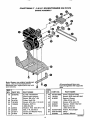
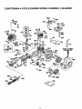
CRAFTSMAN
9"-3,8H.P.EDGER/TRIMMER
536.797470
ENGINE
ASSEMBLY
Note: Always use original equipment
parts. Use of s_n/lcelreplacement
_adsother than originalpads may void
,our warranty
Al$ unnumbered items ere
Interchangeable with opposite
side
REF
NO.
REF°
NO. PART NO.
,
PART NO.
PART NAME
,,,,,,
10
ENGINE
12
20
22
24
48148
314781
181608
120638
26
29
3O
32
45602
32668
313011
51600
3.8 HP 143 963507
40
41
42
(See Engine pages)
Screw, 3/8-16 x 1.00
Pulley, Half V3L
Screw, 5116-24x 1 O0 HHC
Washer, SPTLK
,328x 60x,09
Washer, Flat 333x 87x 11_
Belt, V 4L 32.60LG
Screw and Washer Assy
Guide, Belt
331281-833
181624
315095
43 173030
44! 308237
451 315095
80
81
323534-833
308154-833
339690
Cover, Engine F
Screw, 5/16-24>
HHC
Spacer, Sleeve
.335x 431 x2.50
Screw, 5/16-24>
Spacer, 3221D .562 OD
Spacer, Sleeve
.335x 431 x250
Frame, Assy Ec
Strap
Owner*s Manua
|
]
323095D
t6
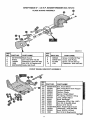
CRAFTSMAN 9" - 3°8 HoP.EDGER/TRIMMER 536.797470
BLADEGUARDASSEMBLY
_)
332247O
REF
NO,
PART NO.
1
33io76,5
2
3
4
5
PART NAME
Blade Guard
57072
Can', Bolt5tt6-18x,63
120393
Flatwasher,344x,69x065
1498
Nut, 5116-18 Reghexctrlk
326748-83.3 Guide, Belt Front
NI.N_ PART NO,
J 6 _
I 8 J 53405-833
I 9 I 411666
I IREF:I
10 I
PART NAME
Screw, 114-20x,50 Tap
Cover, Quill Pulley
Screw, 10-24x 50 Tap
Flat'washer 203x 56x 040
1501
FRONT WHEEL BRACKET ASSEMBLY
REF,
NO. PART NO.
150
151
152
153
154
t55
156
157
158
159
160
161
162
163
164
339299-833
331422
338614
325892
331421
332002
331419
20252
22265
45905
5133-3
331394-833
120393
339388
1495
PART NAME
A I Front
.....
Rod, Front Mount Curb Hopper
Pushnuto Washer
Washer, Plastic
Spacer, Height Adjust
Pin, Spring. 187Diaxt 50Lg
Lever, Height Adjust
Knob, Rectangle
Flatwasher .515xl. 38x.119PL
Nut, 3/8-16 Hwdfltk Mack
Screw, 5116-18x.63
Plate, Hetght Adjust Quad
Flatwasher, .344x,69x 065
Knob, W/5!16-18 Stud
Nut, 5/16-t8 Reghexctdk
3317650
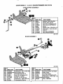
CRAFTSMAN 9" - 3.8 H,P, EDGER/TRIMMER 536,797470
CURB HOPPERASSEMBLY
REF.
NO.
PART NO,
i170
171
172
180
181
182
183
184
185
186
6842
180077
t498
126380
8O82
45222
120393
!3527
120376
310896
PART NAME
Bracket, Curb Hop Mnt
Screw, 5116.18x 75
Nut, 5/16-18 Reghexctdk
Carr. Bolt, 5/16-18x200
Clev;s
Spacer, Slav 356x.63xl o01
Flatwasher _344x69x 065
Knob, T
Nut, 5116-t8 Reghex
Rod, Wheel Support
32317gD
BLADE ASSEMBLY
323129C
REF.
NO. PART NO.
30O
120396
!3Ol 338656-833
302 308254
305 1499
310 308243
3il
411666
312
1501
32O 51603
REF=
NO. PART NO.
PART NAME
Flatwasher,_531xtO6x_095
QuillSupptAssy
ShoulderBolt3!8-16
Nut,3f8-16 Reghexctdk
Deflector.Rubber
Screw,10-16x.50Tap
Flatwasher,,203x,56x040
Qompression
Spring
PART NAME
,, _,,,_,,,,_,,,
.,,,,,,,,_,,
32t
322
323
325
329
330
33't
t8
338070
Quill Assembly, Lrg Suppl
308466
Index Lever
308155
Torsion Spdng
1498
Nut, 5116-18 Reghexctrlk
22265
Flatwasher; 515xl 38x 1t9
334056-853 Blade Edger
46023
Nut, l!=20Wdfl
_,
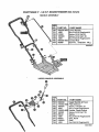
CRAFTSMAN 9" +3,8 H+P. EDGER/TRIMMER 536.797470
HANDLE ASSEMBLY
i REF.
PART NAME
INO, _PART NO.
720
332232-853 Lower-i_a;_die
721
1498
51333
726 180083
728 1498
750. 580292-853
754 36368
722
Nut, 5/16+18 Reghexctrtk
Screw. 5116-18x,,63
Screw, 5116-18xt, 50
Nut, 5/16-18 Reghe_ctrtk
Control Rod
Hair Pin, _072Diaxl. 13Lg
330225D
UPPER HANDLE ASSEMBLY
@
REF.
NO. PART NO,
@
725
731
732
735
737
738
739
740
741
743
745
332239
310052+85_
180024
1502
310050-85_
180081
25644
1498
56924
310053
1499
PART NAME
Upper Handle & Foam
Plate Selecter
Screw, 1t4+29xl ,25
Nut, 114-20 Reghexctdk
Handle, Depth Adjust
Screw, 5116-18xl 25
Spdng
Nut, 5116+18 Reghexctdk
Grip, Hand
Stud
Nut. 3/8-16 Reghexctdk
323136[3
CRAFTSMAN 9" - 3.8 H.P. EDGER 536°797470
TIRES ASSEMBLY
REF.
NO.
1
2
3
4
5
6
7
8
9
10
PART NO.
336545
180113
t 20393
51887
55273
310716
310715
41529
2968
121222
PART NAME
_re & RimSXl,,75
Screw, 5/16-18x3.00
Flatwasher, 344x.69x.065
Spacer, Slev 328xA95x139
Nut, 5116-18 Wdfllk
Shoulder Bolt, 3/6-16
Spacer. Slev 390x,70x 70
Nut, 3/6-16 Hxctrlkjam
Flatwasher oS04x]Sx.059
Cotter Pin
332250B
0
0
0
0
DECALS
NO.
PART NAME
PART NO.I
820 338984
82_ ' 69711
822
823 338982
824 333873
825 312548
826 333874
I
Decal. Recoil Cover
Decal, Information Danger
Reference Only
Deca!. 3 8 Sears Edger
Decal, Angle indicator
Decal, Quadrant Selector
Decal, Blade Cover
323t37D
2O
CRAFTSMAH
,_.CYCLE ENGINE MODEL HUMBER: 143.963507
215
2t
CRAFTSMAN
FIEF.
_10.
PART NO.
36560
4
5
_6
17
18
19
._0
_5
26727
28277
31334
31336
31335
650548
34593
32600
36552
._5A
_6
._6A
_0
I0
|o
35883
650802
650926
359O2
34514
34515
to
34516
tl
325388
325488
32549B
_2
_,2
12
$3
_5
28986
28987
28988
20381
309638
16
18
€9
50
50
_5
59
7O
32610A
!27241
128594
33149A
29745
650128
27677A
35863A
72
75
B0
81
82
27642
26208
30574A
30590A
30591
83
86
B9
90
92
93
100
102
103
30588A
650488
610961
611195
650815
650816
34443A
650872
651007
t10
119
120
t25
35182
36437
36438
36471
125
36472
126
293148
!26
293t5C
130
130A
650694
6021A
4-CYCLE ENGINE MODEL NUMBER: 143.963507
PART NAME
Cy_Inder
_ncL 2, 20, 72, & 125}
uowel
Washer
GovernorRod
GovernorLever
GovernorLever Clamp
Screw, 8-32 x 5116"
ExtensionSpring
Oil Seal
BlowerHslng Baifle
nd. 262)
alfle Extension
Screw, 1t4-20 x 5/8"
Screw, 8-32 x 21t64"
Crankshaft
Piston,Pin& RingSet
Piston,Pin& Ring Set
(_,010 OS)
'
ston,Pin & Ring Set
(].020OS)
start& RingAssy
(Sld) (lnc143)
Piston & Pin Assy
010" OS) Incl 43
tston& Pin Assy
(.020" OS (Inc143)
Ring Sat (Std)
Ring Set (010" OS)
Ring Set ( 020" OS)
PistonPin RetainRing
ConnectingRod Assy
ncl 46 & 49)
onnecttngRod Bolt
Valve Ltlter
Oil Dipper
Camshaft (BCR)
Blower HousingExt
Screw, 10..24x 1/2"
Cylinder Cover Gasket
Cylinder Cover ({nci 75
thru 83, 311)
Oil Drain Plug
Oit Seal
Governor Shaft
Washer
Governor Gear Assy
(tnc181)
Governor Spool
Screw 114_20x 1-1t4"
FlywheelKey
Flywheel
Believi]leWasher
Flywheel Nut
Solid State Ignition
Solid State Mting Stud
Screw, Torx T-15, 10-24
x 15116"
Ground Wire
Cylinder Head Gasket
Cylinder Head (Incl 130)
Exhaust Vatve (Std)
ncL151)
xhaustValve (1132" OS)
Inc1151)
ntake Valve (Std)
(Inci 151)
tntake Valve (1/32" OS)
(Inc1151)
Screw 5/16-18 x 2"
Screw 5tt6-18 x 1-1/2"
FIEF_
_0=
PART NO.
_32
_35
650708
33636
W50
_69
170
f7!
172
173
174
178
31672
31673
27234A
27666
31410
34146
35350
30200
29752
179
t82
t84
30593
620t
26758
t85
36703
185
.>00
31341
35677
Z03
Z04
206
_.09
Z09A
215
31342
650549
610973
650139
30322
32410
650451
26754A
650932
34338
35797
35066
35065
35585
650737
35493
650988
36467A
650926
29774
26460
65O665
35591
_3
?.24
238
Z39
241
245
250
260
262
275
277
285
287
290
292
298
B00
301
311
313
339
340
342
345
370A
3708
370K
380
390
400
416
35335
27625
34080
28212
417
650760
35828
650751
32664
36261
35703
36695
632589
590732
36439
36085
PART NAME
Washer
Resistor Spark Plug
(CJ8)
Valve Spring
Valve Spdng Cap
Valve Cover Gasket
Breather Body
Breather E]ement
Valve Cover
Breather Tube
S_ew 10-24 x 9t16"
Nut & LockWasher
t/4-28
Retainer Clip
Screw 1/4-28 x 7/8"
Carburetorto Intake
Pipe Gasket
intake Pipe
Inc1182, 184, 224)
Governor Link
ControlBreaker (lncl.
203 thru209A) •
CompresstonSpdng
Screw 5,40 x 7/16"
Terminal
Screw 8-32 x t/2"
Locknuf,8-32
Centre{Knob
Screw 1/4-20 x 1"
Intake Pipe Gasket
Screw 10-32 x 49164"
Air Clef,net Gasket
Air Cleaner Collar
Air Cleaner F{iter
Air Cleaner Cover
Blower Housing
Screw 1/4-20 x 1/2"
Mullter (Ind 277)
Screw 1/4-20 x 2-5116"
Starter Cup
Screw 8-32 x 21/64"
Fuel Line
Fuel Line Clamp
Screw 1/4-15 x 7/8"
Fuel Tank
(lnc1292 & 30t)
Fuel Cap
Oil Fill Plug
Spacer
Spacer
FuelTank Bracket
Screw 1t4-20 x 7t16"
Baffle Heat
LubricationDecal
Control Decal
Starter Decal
Carburetor (Ind 184)
Rewind Starter
Gasket Set
Spark ArrestorKit(incl
417}(opt)
Screw, 8-32x3/8" (opt)
This engine could have been buii!with 590738
starter. Refer to the designo! the rope pulley
strengthdbsfor part identification.|ndividual start_
_arts do not interchange,
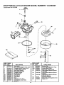
CRAFTSMAN
4-CYCLE ENGINE MODEL NUMBER:
143.963507
Carburetor No 632589
/
!
/
\
28
l
/
27
I
/
I
\
REF_ PART
NO. NO.
31
631022'
35
36O45
35A 632647
40
632591
41
630740
PARTNAME
Carburetor
ll_CL184of EnginePartsUst
rottleShaft& LeverAss'y
ThrottleReturn Spring
DustSealWasher
DustSeal(Throttle)
ThrotterShutter
ShutterScrew
FuelFitting
FloatBowl
FloatShaft
Float
FloatBow!"O" Ring
InletNeedle,Seat, Clip
(inct31)
42
1630739
43
630738
44
48
6O
23
27110
631027
632592
PART NAME
sp_ng
clip'
_
PrimerBulb/RetainerRing
PrimerBulbFilter
MainAdj. ScrewAss_
High Speed Mixturescrew
*O" Ring
HighSpeed MixtureScrew
Washer
HighSpeed MixtureScrew
TensionSpring
BowlNutWasher
WelchP[_ug
Almospherlc
Vent
Repair Kit
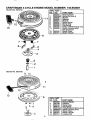
CRAFTSMAN
4-CYCLE ENGINE MODEL NUMBER: 143.963507
Starter No_ 590732
REF PART
NO. NO,
590372
t
590599A
PART NAME
RewindStarter
Spring,Pin (Inct 4)
Washer
Retainer
Washer
Brake Spring
Starter Dog
590699590698
Dog S_ng
590700
Pugey Rewind Sprg A
590695
Starter Housing Assy
(40 a grommet)
590535
Starter Rope
590701
Starter Handle
590600
590696
590601
590697
i3
11
12
13
___
7--t
--,
7 -8
-3
Starter Nor 590738
/
13
REF, PART
NO. NO.
590738"'
3
590740
6
590616
7
590617
8
590618A
11 590687A
12 590535
!3 590701
14 590741
PART NAME
RewindStarter
Retainer
StarterDog
DOg;pSring
Pulley&Rewind
SpringAss1
_tarter HousingAssy
StarterRope
StarterHandle
LockingTab
)RTADORA
Contenldo
25
Garantia
25
Reglas de seguridad
25-27
Contenido del paquete con articulos de
ferreteda
27
Montaje
28-30
Operacton
30-35
GARANTIA
Mantenimtento
35*36
Servlctoy Ajustes
37_38
Almacenamiento
38-39
ldentlficacionde Problemas
39
Partes de Repuesto
16-20
Motor Partes de Repuesto
21-24
Orden de partes/servicio Contratapa
LLIMITADA DE UNO AI_O DE LA CANTEADORAJ
RECORTADORA
CRAFTSMAN
Por uno aSo a parttrde la fecha de compra, cuando esta Canteadora/Recortadora
Craftsman se mantenga, lubr]quey afine seg_n tas instruccionesen el manual del
duetio, Sears reperar_, gratis, todo defector en el material y la mano de obra
Si la Canteadora/Recortadora Craftsman se usa para fines comerciales o de arriendo,
est& garant{a se aplica s61opor 90 dfas, a partir de la fecha de compra.
Esta garant!a no cubre lo siguiente:
. Arfculos desgastables que se desgastan durante el uso normal tales como las
bujfas,etco
• Reparactones necesarias debido el abuso o ala negiigencia dei operador,
incluy_ndose a los ctguefiales doblados y a la falta de mentenimiento el equipo
segL_nlas instruccionesque se encuentran en el manual det duefio_
EL SERVICIO DE GARANTIA SE ENCUENTRA DtSPONIBLE AL DEVOLVER LA
CANTEADORAiRECORTADORA CRAFTSMAN AL CENTRO/DEPARTAMENTO DE
SERVICIO SEARS MAS CERCANO EN LOS ESTADOS UNIDOS. ESTA GARANTIA
SOLO SE APLICA CUANDO ESTE PRODUCTO SE USA EN LOS ESTADOS
UNIDOSo
Esta garantia _eotorga derechos legales especificos, y puede que tambi_n tenga
otros derechos que varfan de estado a estado.
Seers, Roebuck and Co., Depadamento D/817WA; Hoffman Estates, IL 60179
BUSQUE
_
ESTE SIMBOLO
QUE SE_ALA
LAS PRECAUCIONES
MPORTANCIA.
QUtERE DECIR * IlIATENC!ONHI
ESTA COMPROMETIDA,
PRECAUTION: Siempre desconecte
el alambre de le bujia y pongalo en donde
no pueda entrar en contactocon esta pare
evitar el arranque por accidente durante le
prepamcion, el transporte, el aiuste o
cuando se hagen reparactones
IMPORTANTE: Los estandares de
seguridad demandan los controles que
exigen la mintmo el riesgo de lesiones. Su
canteadora/recortadora vtene equipada co¢,:
dichos controlesoPor ntngun motivo irate de
anuler le funclon de control que exige la
presencia del operador..
ANTES DE CADA USO
• Lea el manual del duefio
cutdadosamente. Familiadcese
completamente con los controles y con el
uso adecuado de la canteadora/
DE SEGURtDAD
DE
ilIESTE ALERTAHI SU SEGURIDAD
recortadora_ Sepa c6mo pararla y
desenganchar los controles r_pidamenteo
• No opere la canteadorairecortadora sin
usar ropa exterior adecuada. Use zapatos
que mejoren el equilibdo en las
supedicies resbalosaso
• Mantenga el &rea de operacibn
despejada de toda {a genre,
especialmente, tos niSos pequeSos y los
animales dom_sticos.
• inspecctone cuidadosamente et &reaen
donde se va a user la canteedora]
recortadora y remueva todos los objetos
extrafios,
SEGURtDAD DE COMBUSTIBLE
• Maneje el combustible con cuidado; es
altamente inflamable,
• Use un envase adecuado.
25
• Revise el suminlstm de combustibleantes
de cada uso, permitiendoqua exists
espacto paraia expansl6n pussel calordal
motoryto solpueden hacerque se expanda
el combustible_
° Uene el estanquede combustibleafuera
con muchocuidado, NuncaIIene el
estanque de combustibleen recintos
carrados_ Vuelva s colocarla tapa del
estanquede combustible en forma seguray
limpie el combustiblederramado.
• Nunca remueva la tapa del estanque de
combustibleo agregue combustiblea un
motorque est,. funcionando o que est&
caltente_
• Nunca atmacenecombustibleo la
canteadorairecortadora con combustibleen
el estanque dentro de un edificlo en donde
los gases puedan atcanzar unaHams
expuesta.,
SEGURIDAD
DE OPERACi0N
• Nuncapermttaque losni_os o
adolescentes J6venesoperen su
canteadora/recortadota. Mant_ngalos
alejados cuando est_ en operacibm Nunca
perrnita qua los adultos operen la
canteadorairecortadora sin los
conocimiantosadecuados.
• No opera la mAquIna sl est,t tomando
drogas u otras medicinas qua pudiera
causar somnoiencia o qua pudieran afectar
su habitidad pars operararesta m&quina
• No opera esta m_.quinasI su estado
emocional o fisico no le permits operaria
con segurIdad_
• Siempra use anteojos de seguridad o
protecctonas para fos ojos durante la
operacl6no cuando hags ajustes o
reparacionespars protegersus ojoscontta
objetos extraF,osqua la canteadora/
recortadora pueda lanzar
° No ponga las manos nl los pies cerca o
debajo de partes rotatodas,
• Tangs sumo cuidadocuando opera o
atraviese entradas de autom(Svilesde ripio,
senderoso camtnos, Mant_ngase alerta
de peltgrosescondidos o it&rico.
•Tenga culdadopars evitar resbalarse o
caerse_
• Nunca opere ia canteador_recortadorasin
las protecciones y tasplanchasadecuadas,
o sin otrosdtspositosde protecctbnde la
seguddad en su lugar.
o Nunca opera la canteadora/recortadoraa
aires velocidadesde transportsen
superficiesresbalosas. Mire hacla atrbs y
tenga cutdadocuandoretroceda.
• Nuncapermits la presenciade
espectadores cema de la canteadora/
recortadora.
• Mantengaa los nihosy a los anlmales
dom_sticos alejados mtentras se est_ en
operadbn
• Nunca opere is canteadora/recortsdorasin
buenavlslbllidado luz.
• No hags funclonarel motoren recfntoe
cerrados. Losgases de escape son
paligrosos(conttenenMONOXIDO DE
CARBONO, UN GAS SIN OLOR QUE
CAUSA LA MUERTE).
• Tome todas lab precaucionesposlbles
cuandodeja la canteadora./recortadora
desatendida, Pare el motor,
• No sobrecarguela capaddad de la
canteadors/recortadoratrstando de canteat
muy profundamsntea muchs velocldad.
ALMACENAMIENTO
CON
SEGURIDAD
• Sternprereft_raseala secdbn de
almacenamlentodal manual del due_o
_mara
veriflcarlosdstalles de
portanclaslla canteadora]
recortadorase va a almscenar potun
largo perIodode tiempo.
° Nunca atmacene la canteadora/recortadota
con combustibleen el estanque de combus.
tlbledentro de un edlflcio en donde se
encuentrenpresentesfuentes de lgnld6n,
tales comolos caJentadoresde ague o de1
ambtente,secadorssde ropay otros
artefactosparecidos Permitsqua se enfde
el motor antes de guardarlo en elgin lugar
cerrado.
• Mantenga ta canteadora/recortadoraen
condictonesde trabaJosegutas. Revise
todos[os sujetadoresa intervalosfrecuentes
pata veriflcarsl est&n spretados en forms
segurao
SEGURIDAD
DE REPARAClONES/
AJUSTES
• Despu_sde pegarle a objetos extra_os, pare
el motor. Remueva el alambre de la bujIa, y
mant_ngalo alejado de _sta pars evitar e!
arranque pot accidents, Inspecclone
cuidadosamente la canteadora!recortadora
pars verfficar slest& daf_aday repare los
daSos antes de velvet a arrancar y operar {a
canteadora/recort adore.
• Si la canteadora/recortadoraempleza a
vtbrar anormalmente, pare el motor y revise
Inmediatamentela causao La vibrac_6n,
normaimente es un aviso de probiemas_
• Pare la cuchUiacuandoabandons Is.
posictbn de operact(Sm
Tambl6n, pare el
motory desconecte el alambre de la bujla
antes de destaponar la cuchi]lsy cuando
hags reparaciones, aJusteso lnspecctones.
• Cuando hags limpiezas, reparaciones o
Inspecciones, apague el motor y asegr3rese
qua todas las partes en rnovimiento se
hayan detenido.
• Nunca trate de hacer aJustes mientras el
motor estA funcionando (excepto ¢uando
especlficamante Io recomIende el
fabricante).
28
eq_upads
ADVERTENClA:
vlene
conun motorde EstaUnldad
combusti6nihterna
y no se debe user sobre, o cerca, do un
terrenono desarrollado cublertbde bosques,
de arbustoso de c_sped; a menos que el
ststema de escape del motor venga equlpado
conun amortiguadorde chtspasquacumpla
conlas leyes localeso estat_es (si exlstan), Si
se usa un amortlguador de chlspas,e!
operadordebe mantenedoan condlclonesdo
trabajoeficientes,
En el estado de CaIifornla,la lay exige Io
anterior (Seccibn4442 det =California Public
ResourcesCode"(Decretode Recursos
Pflbllcos de CaJifomia).Otros estados puedan
centarcon otras 1eyesparecidas, Las leyes
federates se apltcanen las tierrasfederates,,
Su Centrede Ser¢tdo Autodzado Sears m&s
cercanotJenedlsponible un amodiguedor de
chlspas/stlenc_ador
(vea la seccfSn "PARTES
DE REPUESTO" en este manual).
Contenldo de la bolsa con las partes, (se muestran del tamano real)
(4) -
@ I
de cabeza (8) - Tuercaade cabeza
hexagonalde
hexagonalde 5t16_18 (1) - Espaclador.70 {conJuntode la
5!16-18x 518pulgr*dss
rueda traaere Izqu|erda)
A
(1) - Tuercas de cabeza _J_
Ijl===lJ=Jl
(1) - Pernos 3/8-16 x 1o400pu|gadas
(2) - Horqu[|tas
hexagonal3/8-16
0---....
,,,.,om,,,o,°oab.z.,
@
(4)- Torn|ilosde csbeza
(1) -Tuercae de segur|dad de
bride anchs de cabeza 5/16.18
1 - ClavlJade horqutlls
hexagonalde 5!16-18x1-1t2
@ ©! ...........
.. -I
(1) - 1o39Espe¢|ador
(conJuntode ta ruedadelantera)
(1) - 1/2 x 3/4 pulgeds
Arandelaplane (con|untode ts rueds trasera derecha)
(2) - 11/32xl 1116pulgsda
Arandelesplans
(conjuntode ls rueda
delsntera)
Partes empaquetadas en forma separada en la caja de carton (no
muestran deltamatto real)
(1) - Varilla de control
(3) - Ruedes
,Igo Inferior (1) -Mango superlores
21_Manuel
dellss
Due_o
(no(not
ae mueatra)
Boise con
partes
se mueslra)
'_1J_
1 - Envsse de aceite SAE30
27
NO INFO
NO
INFO
VISTA DESDE EL LADO DERECHO DE LA
UNtDAD
MangoInferior
del
lada
%
Pemos
del
inferior
/
LISTA DE REVISION
Antes de operar y de disfru!ar de su
canteadora/recortadora nuevo, le
deseamos que reciba ef mej_r rendimiento
y la mayor satisfacclohde esti_ pi'oductode
calidad+
HAGA EL FAVOR DE REVISAR LA USTA
A CONTtNUACION:
/
Se han compietado
todas
las
instrucciones de montaje.
J
No quedan partes sueltas en la caja de
cad6n+
,/
Revise si hay sujetadores sueltos,
AI mismo tiempo que aprende como usar
su canteadora./recortadora, preste atencion
extra a los puntos de tmportancia qua se
presentan a continuacion:
//
El aceite de! motor tiene que Ilegar al
nivel adecuado+
Jd El estanque de combustible tiene que
estar llano con gasolina sin plomo
regular, nueva y limpia+
_/
Famiiiar+cese con todos los controles +
su ubicaci6n y su funci6n+ Op_re[os
antes de hacer arrancar el motor+
CONOZCA SU CANTEADORA/RECORTADORA
LEA ESTE MANUAL DEL DUEllO _' LAS REGLAS DE SEGURIDAD ANTES DE OPERAR
LA CANTEADORNRECORTADORA, Compare las ilustracionescon su canteadora/
recortadora para familtarizarse con la ubicaci6n de los diversos controtes y ajustes,,Guarde
este manual para referencia en el future.
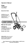
14
Rdpide
Despacio
Parar
Borondetcebador
embrague
Varilla de control
Tapa del
desposito de
relleno del
bustible
del cebador
ienciador
Patanca d_
control de
aceleracion,
VISTA CUCHtLLA
Mango€
ajustable
ajustable
3o
Control
dela aceleraclon - Se usa para
contro}arla veWocidadde_motor_
Siempre desenganche la cuchilla de code y
pare el motor,
PARA USAR EL CONTROL DE LA
ACELERAClON
BorOn del cebador - Inyecta combustible
directamente en el mOttiple del carburador
para arra'nques m&s r,_idos.
Mango dei arrancador - El motor de esta
Canteadora/recortorador vtene equipado
con un arrancador de culateo de tire f&cilo
Palanca del embrague - Se usa para
hacer arrancar y parar la cuchilla y controlar
la profundidad del coda°
Palanca de Ind|ce - Permite el ajuste
desde la postdbn de canteado (vertical) a la
de recorte (horizontal).. Para cambiar de
posici6n, fire ta palanca de lndice y rote el
conjunto del cuerpo al _ngu?o o a la
posicl6n deseada_
Proteccton de la cuchilla - Se usa para
evitar qua las piedras y otros materiales
sean tanzados hacia el operador.
Rueda traaera aJustable - La rueda trasera
derecha es ajustable para saitar sobre la
acera (para nivelar la canteadora/
recortadora cuando se cantea a Io largo de
la acera),
Rueda delantera aJuatable - La rueda
delantera as ajustable de lade para
balancear..Tambi_n, se peude ajustar hacta
abajo para subirseper el fiance de la acera
(para nivelar la conteadora/recodadora
cuando se est_ canteando a Io largo de la
ace ra).
COMO USAR SU CANTEADORA/
RECORTADORA
,_
PRECAUCION:
La operaci6n de
esta canteadora/recortadora puede hacer
qua saffen objetos extraSos dentro de sus
ojos, Io que puede producir daSos graves
en 6stosoSfempre use anteojos de
seguridad o protecciones para los ojos al
operar la canteadora/recortadora,
Recomendamos el use de anteojos de
seguridad est&ndar o la M_scara de
Seguridad de Visi6n Amplia, para use sobre
los espeJuelos.
PARADA
• Para parar el motor, aseg_rese que la
palanca del embrague est_
completamente hasta atria (o hacia
arriba) y mueva la palanca de control de
ta aceleraci6n a la posici6nde PARADA
/_
PRECAUClON:
Nunca deje la
canteadora/recortadora desatendida
mientras qua el motor estafuncionando.
• He,ga funcionar el motor a velocidad
compieta durante el use normal,
• Empuje la pafanca de control de la
estrangulacl6n hacia arriba para
aumentar le velocldad, hacia abajo para
disminuir la velocidad,.
PARA USAR BOTON DEL CEBADOR
• Mueva la palanca de control de la
aceteraci6n, vea pagina 30 a la posiciSn
de FLINCIONAMIENTO (RUN)..
• Ernpuje el bot6n del cebador cinco
veces, vea pagfna30,. Espere
atrededor de dos segundos entre cada
empujSno
• No use el cebador para velvet a
arrancar un motor caliente despu_s de
una parada cortao
PARA USAR PALANCA DEL
EMBRAGUE
• Haga arrancar el motor y meuva la
palanca del embrague hacia adelante
(o hacia abajo) para enganchar la cuchiIla
de corte_
• Seleccione la profundidad del canteo
que neces[ta° Hay cinco selecciones
hasta 2-3/4 pulgadas de profundidad.
IMPORTANTE: En el case de qua se
necesite cantear con mucha
profundidad, recomendamos que
pdmero se haga un corte menos
profundo, luego codes a mas
profundidad hasta qua se logre la
profundidad deseada.
PARA USAR PALANCA
DE INDICE
(OPERACtON DE RECORTE)
. Pare el motory desconecte e] alambre
de la buj|a..
• Suelte la mani!ia, vea figura, en el braze
de la rueda delantera y deslice las
ruedas, completamente, hacia el lade
derecho.
• Apriete la mani]la en forma segura.
31
_a
nIvelada cuando la rueda izquierda est,i
en el flanco de la acerao
• Apriete ta mantlla T an forma segura.
° Vuelve a conectar et alambre de la bujla
y haga arranca el motor, La profundidad
del ajuste del porte es la misma descrita
en el p,_rrafode Operact6n de Canteado.
PRECAUCION:
Las ruedas
nteras tienen que estar en la postcion
de la extrema derecha pare evitar que la
cuchi_lale pegue a las ruedas cuando se
esta en la posictonde recorte_
• Tire la palanca de I'nd[ce fuera de su
muesca, vea figura abaj0, y p6ngala en
ta muesca marcada 90°,
ManUiaI
• Vuelva a conectar la bujfa y haga
arrancar el motor° Mueva la palanca de!
embrague a la altura de recorte deseada.
,_
PRECAUCION:
Nunca daje la
canteadora!recortadora desatendida
mientras que el motor estafuncionando,
Siempre desenganche la cuchiIla cortadora
y pare el motor_ Operacion pare subirse al
flanco de la acera.
Proteccion
de la
ilia
Brazo
delantera
alturadelflanco
de la acera
delantera
_
PRECAUCiON:
Mantengase
alejado de la cuchiltamtatoria. La cuchilla
puede producir lesiones.
Palanca
ANTES
PALANCA DE INDICE EN LA MUESCA
MARCADA"90"
DE HACER
ARRANCAR
EL
MOTOR
REVISION DE LOS CONTROLES ANTES
PARA USAR SALTAR LA ACERA
DE USARSE
La caracteristica de las ruedas detanteras y
Se deben reviser todos los controles pare
las traseras ajustables permite qua la
verificar si funcionan en forma adecuada
canteadora/recortadora se use en
antes de dar servic[o o de hayer arrancar el
superficies dtsparejas tales como un flanco '
motor,
de una acera seg0n se muestraen la
• Mueva la palanca de control def
proxima figura.
embrague alas seis posiciones en la
• Pare el motor y desconecte el alambre
plancha de selecciSn, AsegOrese qua la
de !s bujfa°
palanca del embrague caiga an los seis
• Suelte !a manilla en e! brazo de la rueda
agujeros, yea pagina 30.
delantera y destice la rueda a la major
, Vuelvala palanca del embrague at
posict6n para salvar el flanco de la acera
y equilibrar la unidad.
agujero m&s trasero posibie en la
plancha de selecciSno
• Apriete la manffla en forma segura.
RELLENO/AGREGAR
ACEITE:
• Use la paianca de ajuste de ta altura del
flanco de la acera, y baje la rueda
Esta canteadora rue enviada con un
delantera ala postci6n qua coloca ta
contenedor de aceite para motor SAE30.
conteadora!recortadora al mismo nivel
Este aceite debar& ser aSadido al motor
con la rueda trasera izquierda en la
antes de operarlo_ Remueva la tapadera
supefficie desniveiada (flanco de la
del nivel de aceite y Ilene ta caja del
acera) o
ctg0eSat hasta la II[nea del aceite (20
• Suelte la maniUa Ten el lado interior
onzas). NO LO LLENE DEMASIADO.
trasero derecho del bastidor principalque
RECOMENDACIONES
PARA EL
asegura la varilla de soperte de la rueda,
ACEITE
Vea proximo figure,
. Desl[ce la rueda trasera hacia abajo
Use solamente aceite de detergente de alta
haste qua la canteadora/recortadora est_
calidad clasificadocon la clasificacidn SG
32
deservicio
APIo Seleccione la calidad de
vlscosidad del aceite SAE seg0n su
temperature de operacidn esperada:
con alcohol(conocidos como gasohol), o el
uso separaci6n y formaci6n de ._cidos
durante et almacenamtento._ La gasolina
acidica puede daSar el sistema del combustible de un motor durante el
almacenamiento, Pare eviler los problemas
con el motor, se debe vaciar el sistema de
combustible antes de guardarlo pot un
peHodo de 30 dlas o re&s,,Vacfe el
estanque de combustible, haga arrancar ei
motor y h&gato funcionar haste qua las
Ifneas det combustible y el carburador
queden vacfoso La prSxima temporada use
comt)ustib?e nuevoo Vea las instrucciones
Pare El Almacenamiento para m&s
!nformaciSno Nunca use productos de
limpieza para el motor opara el calburador
en el estanque del combustible, pues se
pueden producir daSos permanentes
((
I Mas5W30
Frio <_'_
AVtSO: A pesar de que los aceites de
multivtscosidad (5W30, 10W30, etc,)
mejoran el arranque en ctima fr|o, estos
aceites de multtviscosidadvan a aumentar
el consumo de aceite cuando se usan en
temperatura,s sobre 32°Fo Revise el nLvet
del aceite del motor m&s a menudo, para
evitar un posible daSo en el motor, debido a
qua no tiene suftciente aceite.
PARA AGREGAR
ACEITE AL MOTOR
• Ponga la canteadora en una superficie
nivelada.
• Remueva la tape del depSsitodel relleno
del aceite, vea figurao
• Vuelva a lienar el c&rter del motor con
aceite a trav_s del tubo pare relieno del
aceiteoVaclelo lentamenteo No io liana
demasiadoo Para ia capacidad
aproximada yea las
ESPECIFICACIONES DEL PRODUCTO
en la p&gina de este manual°
. Vuelva a colfocar la tapa del depSsito de
relleno de aceite.
• Revise el aee_teantes de cada uso,
agr_guelo si es necesario_
• Se tiene que cambiar eLaceite en el
c&rter despu(_s de las 2 primates horas
de operac[Sn y despu_s de cada 25
horas de uso, de ahl en adetante.
_bustible
'/_
PRECAUCION:
Nunca reliene el
estanque de gasolina mientras e] motor esta
functonando o catiente, Inmediatamente
limpfela gasotina derramada antes de tratar
de hater arrancar el motor.
DE GASOLINA:
Llene el estanque de combustible con
gasolina de tipo automotriz, limpia, nueva yo
sin plomo,, Aseg_rese qua el envase qua
est&usando para vactar la gasolina est_
limpto y sin polvo u otras partfculas
extraSaso Nunca use la gasoline que pueda
ester rancia debido a los largos pert'odos de
almacenamiento en el envase,
./_ ADVERTENClA:
La experiencia ha
indicado qua los combustibles mezclados
Nunca reltene el
estanque de gasolina mientras el motor
estsa funcionando o calienteo
Inmediatamente limpie la gasoline
derramada antes de tratar de hacer
A
RELLENO
PRECAUCION:
33
ncar el motor.
PRECAUCION:
La gasoline es
inflamabte y se tiene qua tenet cuidado
cuando se maneje o almacene. No Ilene el
estanque de combustible. Nunca llene el
estanque de combustible completamente;
sino qua Ilene el estanque haste dentro de
1/4-1/2 pulgada desde la parte superior
pare permitir espacio para la expansion del
combustible. Siempre flene el estanque de
combustible afuera y use un embudo o un
pico para evitar el derrame. Asegurese de
limpiar toda ta gasoline derramada antes
de hacor arrancar el motor.
Almacene la gasolina en un envase
aprobado y limp[o y mantenga la tapa de
este en su lugar. Guarde la gasoline en un
lugar fresco y bien ventilado; nunca en la
casa. Nunca copre mas gasolina que la que
necesita para 30 dias para asegurar fin
servir de combustible en motores de
combustion interna; por Io tanto, no use la
gasoUna para ningun otro el olor de la
gasolina, mantengala alaejada de su
alcance pues los vaperes son peligrosos de
aspirar, ademas de ser infiamables.
PARA HACER ARRANCAR
EL MOTOR
Antes de hacer arrancar el motor
asegOrese de que haya leido y
comprendido todas las instrucciones que
se dan en las p_ginas anteriores_ La
canteadora viene equipada con un
arrancador de culateo, La operaci6n del
motor es controlada por la palanca de
control de la aceleraci6n_
* Tire la patanca de! embrague
completamente hasta aatr_s (o hacia
arrtba) al agujero m&s trasero posible para
elevar y desenganchar la cuchilla.
. Mueva la palanca de control de la
acelleraci6n (vea figura en pag[na 30) a
la posici6n FAST_
• Empuje el bot6n del cebador cinco
veces, yea figura en pagina 30_ Espere
alrededor de dos (2) segundos entre
cada empuj6n
AMISO: No use el cebador para volver a
arrancar un motor caliente despu_s de una
parada corta.
. Para hacer arrancar un motor, agarre el
mango del arrancador del motor,
firmemente, con su mano derecha.
o Tire back abruptamente, el mango det
arrancador de culateo. NO permita que
el cord6n del arrancador se devuelva
abruptamente, d_jelo que se enrolle
lentamente, mientras se sujeta el mango
del arrancador_
AMISO: Si el motor no arranca despu_s
de tres (3) tiros, empuje el bot6n del
cebador dos (2) veces y tire de nuevo el
cord6n arrancador.
• Par parar el motor, haga funcionar el
motor a velocidad completa durante el u
uso normal
AMISO: La velocidad de ta cuchilla de
corte se controla por medio de la velocidad
det motor_ Para reducir la velocidad de la
cuchilla de code, empuje la palanca de
control de la aceleract6n hacta abajo. Para
aumentar la velocidad de la cuchilla,
empuje la palanca de control de la
aceteraci6n hacla arriba.
• Para parar e! motor, aseg_rese que la
palanca del embrague est6 completamente
hasta atr_s (o hacia arriba) y mueva la
palanca de control de ta aceleraci6n a la
posic[6n de PARADA, yea pagina 30_
//_ ADMERTENClA:
Nunca haga
funcionar el motor en recintos cerrados o en
un area real vent[lada. El escape del motor
contiene monoxido de carbono, ungas sin
olor y que cause la muerte, Mantenga las
manos, 10s pies, el pelo y la ropa suelta
alejados de las partes en movimiento en el
motor c) en la canteadora. Adventencia.,
evite el silenciador y las areas a su
alrededor (vea la figura pagina 30) las
temperaturas pueden sobrepasar 150° Fo
CONSEJOS PARA CANTEAR
• El recorte de los cantos se hace mejor
bajo condiciones see.as.Si el suelo est&
muy mojado, la tierra se aprieta dentro y
alrededor de la cuchi!la productendo un
desgaste prematuro de la correa y un
menor rendimiento
. Si la fierra se aprieta alrededor de la
cuchilla pare el motor, remueva el alambre
de la bujia, y remueva la tierra apretada
antes de continuarrecortando los cantos.
• Si se necesita un recorte en los cantos
muy profundo, recommendamos que
primero se haga uno menos profundo,
para luego cortar a m&s profundidad
hasta que se obtenga la profundidad
deseada,
• Se puede hacer un recorte de cantos
uniforme cuando la qu|ade la cuchi!laest&
funcionando en yen contra de ta
supefficie cuyos cantos que est&
recortando. Vea figura la pagtna 30_
• El recorte de los cantos puede hacerse
para satisfacer cualquiera necesidad
variando el n0mero de las pasadas y la
distancla que hay entre la cuchi[la y el
canto de la superficie que se est&
recortando°
34
ESPECIFICAClONES DEL PRODUCTO RECOMENDACIONES
GENERALES
CABALLOSDE FUERZA:3,8
La garantfa esta canteadora no cubre los
_ESPLAZAMIENTO:
artfculosque hen estado sujetos al abuse o
ala negligencia del operador., Pare recibir e[
valor total de la garantia, el Operador debe
mantener ala canteadora segSn las
instrucciones dadas en este manual, La
Hstade RevisiSn de Mantenim[ento que se
entrega a continuacidn le servir_ de ayuda
al operador para mantener la canteadora en
forma adecuada_
9_52 pulgadas
cuadradas (156 cc)
CAPACIDAD DE :
2,00 cuartos
GASOLINA
(Sin plomo regular)
LUBRICACION:
20 oz, SAE-30W
BUJtA:
Champion C,J-8 or
(Abertura 0.030 pulg)Equivalente
RESPONSABILIDADES
DEL CLIENTE
LISTA DE
REVISION DE
MANTENIMIENTO
Llene las fachas
a medidaque
completa el
servictoregular
REGISTRO
SERVIClO
Daspues
do las
Mm_as
_h eras
Antes! Fracu_
de
onto.
cada monte
use
Cada
5
Hera,
do
Cada
10
Horas
de
Cada
25
Hor_,s
€l=
A comlOAntos
nzos do de!
cads
Almacen
temper, amlonto
uso
uso
uso
ada
de u8o
Lubrlc_
rode,,
ros
puntos
de_Ivo,e
Re91_
c_bi=
ei ni0ei dei acelie m6i0i.
aceiiedelmolo_"
DE
_
_
.......
,t'
_
Gambler el acelte de! me,or
,
=
v"
Reviser l_. bujla
Revt_tacortea
_ _
Apretar tomillos y tuercas
_
|
t,j
Reviser ia cuchii]a per desgasre/dat%o
_,
tJ
.
I
LUBRICAClON
Canteadora
PARA CAMBIAR EL ACEITE DEL
MOTOR
• Desconecte el alambre de la bujia_
• Remueva e! tap6n del drenaje de aceite
(vea figura abajo) y drene et aceite en
un envase plane.
VISTA DESDELA PARTE TRASERA
. Aplique aceite livianode m&guina
despu_s de cada 25 horas de use a
redes las partes movibles, especiatmente
las ruedas_
Motor
• Se tiene que cambiar el aceite en el
c&rterdespu6s de las 2 prlmeras horas
de operaci6n y despu_s de cada 25
horas de use0de ah[ en adelanteVea
pag[na 30,
AVISO: Si la canteaclorase est& usando
en &teas arenosas o polvorosas, cambie el
aceite m_,sfrecuentemente para evitar el
desgaste premature def motor,
el drenaje
aceite
35
FILTRO
DE AIRE
BUJIA
Cambie el fUtro una vez al a_o; mAs a
menudo bajo condiciones poLvorsas o
sucias. NO trate de limpiar o de acettar el
filtro de atre.
Pare {nstalar un filtro de aire nuevo haga 1o
siguiente:
- Desconecte el alambre de la bu/la_ Glre
la cubierta ala izquierda(vea figura
abajo)(en el sentido contrario a tas
manillas del reloj) y remueva la cubterta y
el fiitro de aire de la bdda.
• Desche at filtro de aire.
. Limpie la cubierta y la bride
cutdadosa mente.
• lnserte el filtro de aire nuevo en la
cubierta,
• Empuje la cubierta firmemente en contra
de la brida y girela aia derecha (en el
sentido de las manillas del reloj) tanto
como sea posib}e(vea figure abajo).
Aseg0rese qua los retenes est_n
asegurados alrededor de la brtda.
• Vuelva a conectar el alambre de la bujfa.
Bdda
Orej
Llmpie ta bujia y vuelva a ajustar ta abertura
peri6dicamenteoLimpie eJ_,rea alrededor de
ta base de ta bujla antes de removerla, para
evitar qua la mugre entre en el motor.
Gamble la bujla si los electrodos est&n
picados o quemados o si la pomelana est,.
partida. Limpie la bujla rascando
cuidadosamente los electrodos (no use
charro de arena o un cepiUode atambre):
Aseg_rese qua la bujla est_ limpia y que no
tenga materiales extra_os. Revise la
abertura de !os etectrodos con medidor de
extraSoso Revise la abertura de los
electrodos con medidor de clnta de alambre
y vuelva a ajustarla a 0.030 si es
necesario_Si se necesita una bujla nueva,
refi_rase al manual de Operacibn y
Mantenimiento del Motor para obtener la
buj[a de repuesto adecuadao
Antes de instalar la buj{a, cubra las roscas
con una cape delgada de aceite liviano o
grafito pare asegurarse qua la remocI6n
serA f&cil. Apriete la bujta firmemente en el
motor. Si hay disponib_e una llave de
torsi6n, torsione la bujfa a t5 pies libraso
,_ PRECAUCION:
Siempre pare el motor y desconecte el atambre de la bujla am
tes de hacer reparaciones en la
canteadora,
CAMBIO DE LA CORREA V
Su canteadora viene equipada con una
correa V de un compuesto especial. Si se
desgasta o se quiebra la correa c_mbiela
por una correa del equipo original, segOn se
muestra en la secci6n de Partes de
Repuesto de este manual° NUNCA USE
UN SUBSTITUTO.
• Desconecte et alambre de ta buj_a.
• Tire la palanca del embrague hacia atr_
(o riariba) pare soitar la tensi6n de la
G_ein_elacubterta ala Izquierda
I sentido contrarioalas
I' manillas del re|oj) pare
temoverJa
la
cubiertaala
derecha _nel sentido
deias manillasdelreloj)
parainstaUarla
correa_
Z_ PRECAUCION:
Nunca haga
funcionar el motor sin el elemento del
filtro de aire instalado Un filtro de aire
con defectos puede producir perdida de
la fuerza del motor y puede producir
desgaste excesivo o da_o en los
componentes del motor sise permite qua
la mugre o el polvo entren al motor a
traves del carburador, Si el filtro de aire
esta dafiado o taponado con pelvo o
mugre tiene qua cambiarse
inmediatamente_
• Remueva los dos tomillos superiores de
la cubierta de la polea del motor, yea
figure proximo pagina, y remueva la
cubierta.
• Remove three screws from the belt guard
as shown in figure below°
AVISO: Aseg_rese de no perder el
espadador en el tornillo trasero y los dos
espaciadores largos en el interior°
• Remueva el tornillo delantero qua
asegura la guia de la correa, yea figura,
al motor. Luego suette ef tornilio trasero y
oscite la gu[a de la correa, alej_ndola de
lacotrea.
36
A
•
Remueva los dos torniliosde la
protecclOnde la correa deTantera,
Remueva la protecci6n de la correa,
• Cuidadosamente, reparta la gufa de la
correa detantera pare abrida Io suficiente
como para poder remover la correa de la
poTeadel cuerpo_
• Remueva la correa de las pofeas del
conjunto del cuerpo y del motor e instale
una correa nueva.
• Instale y asegure la protecci6n de la
correa delantera,,
• Asegure la gufa de la correa que se so_t6
anteriormente°
• Vuelva a instalar la cubierta de la polea
del motor y vuelva a conectar et alambre
de la buj[a..
Tomirtosde la
' cubiertade
poteadel
./_ PRECAUCION:
Cuando se remueva
o apriete la tuerca de la cuchilla, siempre
use el metodo que se meustra en la figure
La Ilave suJetadorasiempre tiene que ester
ubicada en la tuerca detras de la cuchilla de
RECAUClON: No irate de affiar est_
cuchilla+Podria hacede daSo ala cuchilla fo
que puede hacer que se quiebre y
posiblemente lesionar al usuado o a algun
espectadoro
Para cambiar la cuchitla, haga Io sigulente:
. Desconecte el alambre de la bujia..
° Remueva la tuerca de seguridad (yea
figure abajo) que asegura la cuchilla al
eje de impulsi6n°
- Remueva la cuchiita°
• Instale la cuchilla nueva, vuelva a instalar
la tuerca de seguridada+ Apriete la tuerca
en forma segura_
• Vuelva a conectar el alambare de fa
Cubierta de la
)olea del motor
bujta+
,_
,,,.,,_
Llave.de.,-'''_
sujec,o.
] _
Llavede
_
_,
_._ _L
I
Cuchma,.--"""_"_T--'_erca
delantero
CAMBIO
de
seguridad
]a correa
PARA AJUSTAR
DE LA CUCHILLA
EL CARBURADOR
El carburador ha sido preconfigurado en la
f&bricay los reajustes no deberian ser
necesarios.. Sin embargo, st el carburador
de hecho necesita ser ajustado, proceda de
la manera siguiente:
La cuchilla de corte est& sujeta al desgaste
y al daSo taies como las picaduras y
abolladuras. Generalmente, esto no va a
afectar su funci6n+
Esta cuchilla ha stdo especiatmente
diseSada para que no necesite afilarse NOT
TRATE DE AFILAR ESTA CUCHILLA Si la
cuchiltaest&desgastada o daSada se tiene
que cambiar°
_fCarburador
_
Tornillos de
Tomillo deajustede
t,_J
alia velocidad
m_-.---_(Apriete
conlos
dedos0nicmente)
• Cierre el torni!lo de ajuste de alta
velocidad a mano.
Protection
37
m
No Io apr_ateen exceso.
Luego _brato 1-1/4 a t-1/2 vualtas
i
Arranque el motor y d_jelo calentar.
Co/oque el contro( de ta aceleraci6n en
MARCHA. Ajuste el tornitlo de ajuste de
alta velocidad hacIa adentro haste qua la
vetocfdad del motor o el sonido se a[tera,
Ajuste el tornillo haole afuera hasta qua
el sontdo de la vetocidad del motor se
altera. Note ta diferencia entre los dos
Ilmites y fije el tornillo en la mitad de ese
rango.
Si el motor tiende a apagarse bajo carga
o no aceterar desde la ve!ocidad baja ala
affa apropiadamente, ajuste el tomillo de
alta vetocidad en incrementos de 1/8 de
vuelta hasta qua el problema se resuelva+
e
Deje qua el motor est6 en marcha sin
perturbaciones durante 30 segundos
entre cada posici6n pare permitir queet
motor reaccione a los ajustes prev!os. ;
IMPORTANTE:
Nunca expertmente
con elgobemador del motor, el cual esta
configuradode fabrtca pare la velocidad
apmpiada del motor+El exceso de
velocidad del motor por enctma del
ajuste de alta velocidad de fabrica puede
ser pellgmso. Si usted cree qua ta afta
veIocidad gobernada por el motor
necesita ser ajustada, pongase en
contacto con su centro de servicio Sears
mas cemano, el cual tlene el equipo y la
experiencia apropiado pare efectuarlos
ajustes necesarios+
;
,&
zrk PRECAUClON:
Nunca almacene
su canteadora en recintos cerrados, en
un area cerrada, real ventilada si Ja
gasofina se va a quadar en el estanque+
Los vapores pueden alcanzar una llama
expuesta, una chtspa o una luz piloto de
una caldeta, calentardor de agua,
secadora de ropa, cigarrillo, etc,
MOTOR
tMPORTANTE:
Es importante evitat qqe
se formen de goma en partes
fundamentates del sistema de combustible
tales como el carburador, el filtro del
combustible, la manguera dat combustible,
la manguera.de! combustible o en el
estanque durante el almacenamiento. La
experiencia tambien !rtdica qua los combustibles mezclados con alcohot(conocIdo
como gasohol o qua tienen etanol o
metanot) pueden atraer humedad: Lo qua
conduce a la separacion y ala formacion
de acidos durante el almacenamiento. La
gasolina acidlca puede da£tar el sistema de
combustible de un motor durante el periodo
de atmacenamiento+
Pare evitae el daSo al motor(sl la
canteadota no se usa por m&s de 30 dfas)
siga los pasos a continuaci6n+
• Pare remover la gasolina, haga funcionar
et motor hasta que el estanque
est@vacio, y pare el motor+
• Si no desea remover la gasolina, se
puede agregar un estabilizador de
combustible(tel como el estabilizador de
combustible Sears Craftsman No+33500)
a cuafquiera mfnimo los dep6sitos de
goma y los &cidos, Si el estanque est&
CANTEADORA
• Limpie la canteadora cuidadosamente;
remueva toda la basuta y seque _a
unidad con fortaci6n,
. Inspecccione las partes desgastadas o
daSadas de la canteadora y apriete todos
los artlcutos de ferreterfa sueltos+
• Acefte todos los puntos descritos en at
p&rrafo de Lubricacibn en la secci6n de
Mantenimento en este manual,
• Almacene la canteadora en un &tea
protegida y c0brala para dade protecci6n
adiciona[.
IMPORTANTE:
Una Buena forrna de
asegurarse qua la canteadora le
entregara un rendimiento maximola
proxima temporada esllevarla, unavez ai
aSo, al centro de setvicio Sears para
revisarla o afinarla+
38
• Cambiar el aceite,
casf vecfo, mezc/e el estabi?izador con
gasoltna nuevan en un envase aparte y
agregue algo de 6sto al estanque,
Siempre sfga les:instrUcciones en el
envase dGilestabiflzador. Luego,. haga
funcionar el motor porlo menos por 10
minutos despues de que se haya
egregado e} estebilizadbr pare permitir
que la mezcla atcance el carburador_
Guarde la canteadora an un lugar
seguro_ Vea la advertencia anterior,
• Almecene la canteadora en Eaposici6n
de opereci6n con las ruedas abajoo Si se
guarda la canteadora en cualqu[era otra
posici6n, el aceite def c_rter puede
entrar en el ciltndro,produciendo un
problema qua necesite servicio
Puede mantener su motor en buenas
condiciones de operacibn durante el
almacenamiento ah
• Lubricar el (_rea def pistbn/cilindro, Esto
se puede hacer removiendo la bujia
primero y rocianclo aceite de motor limpio
en el agujero de la bvjfa. Luego c0bra!o
con un trapo para abosrber el roclo del
aceita, Luego, rote el motor tirando el
arrancadoi dos o ires veces., Finalmente,
vuelva a instalar la bujfa adjunte el
alambre de 6sta.
.............................
PROBLEMA
Arranque dlflcll
CAUSA
CORRECCION
Combustible rancio
Drene el estanquede combustible,
Ll_nelo con combustible nuevo.
Bu)la defectuosa
Limp|ey vuelva a ajustar la
"
abertura de la bujla.
Camble eI filtro de combustib!e....
Llmpie la Itnea del combustible:
revise el estanque de gasolina.
E! motor funclona Fiitr_de! combustib!etaponado
Lfneadel combustibleb!oqueada o
errdtlcamente
estar},quede combustible vac[o
Carburadordesajustado
BuJlamala
Fiiiro
de aire taponado
La cuchllla de
corte no glra
Ajuste el carburador
Umpie y ajuste la abertura
Umplslo golpe_ndolo o cambie el
filtrode aire
Atascamlento
debido a objetos
extraAos
CuchlIlasuelta
Correa V defectuosa
.....................................................
Rodamient0sdel Cuerp0defectuoso
La cuchilla no
corta en forma
Cuchifla dafiada o desgastada
adecuada
Vibraci6n .........................
=" -e-" =Partessueltas
uxu u_v=
........................
Despeje la obstruccibn
Aprtete la tuerca de retencion de
la cuchilla
Cambie la correa V,
Cambie losrodamtentos.
Cambtecuchllia
Pare ei _tor inmediatamente;
apdete todos lospernos. Si
continualavibracaci6n lleve la
un dadal Centrode Servic o Sears
39
For the repair or replacement parts you
need delivered directly to your home
Call 7 arrP7 pm, 7 days a week
1-800-366-PART
(1-800-366-7278)
Para ordenar plezas con entrega
a domiciiio .1"800-659-7084
For in-house major brand repair service
Call 24 hours a day, 7 days a week
1-800-4-REPAIR
(1"800-473-7247)
Para pedir servicio de reparacibn a
domicilio - 1-800-676-5811
For the location of a Sears Parts and
Repair Center in your area
Call 24 hours a day, 7 days a week
1-800-488-1222
e'-l-'lll
For information on purchasing a Sears
Maintenance Agreement or to inquire
about an existing Agreement
Call 9 am -5pm, Monday-Saturday
1-800-827-6655
When requesting service or ordering
parts, always provide the following
information:
• Product Type
• Part Number
• Model Number
, Part Description
America's
RepairSpeciatists
P,=ntsd
tnUS_A=