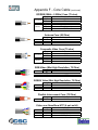
1
Field Operations Manual Chapter One – Overview and Policies Confidential Page 1 Edited 09-26-10 Table of Contents CHAPTER ONE - OVERVIEW I. MISSION STATEMENT II. COMPLIANCE AND CONFIDENTIALITY III. INSTALLATION AND SERVICE - NETWORK POLICIES IV. SERVICE / INSTALLATION - SUBCONTRACTOR RESPONSIBILITIES V. SHIPMENT VERIFICATION VI. WORKMANSHIP/WARRANTY EXPECTATIONS VII. TIMELINESS VIII. COMMUNICATION CHAPTER TWO-INSTALLATION AND SERVICE PROCEDURES I. INSTALLATION AND SERVICE DISPATCH PROCEDURES II. INSTALLATION CLOSE OUT PROCEDURE III. FIELD SERVICE CALL CLOSE OUT PROCEDURE IV. RETURNED MATERIAL AUTHORIZATIONS (RMA'S) CHAPTER THREE - ADMINISTRATION I. INVOICING FOR CONTRACTED INSTALLATIONS II. INVOICING FOR SERVICE WORK CHAPTER FOUR - FIELD STANDARDS I. FIELD INSTALLATION STANDARDS II. TESTING PROCEDURES III. REQUIRED EQUIPMENT FOR INSTALLATION AND SERVICE IV. DBS FIELD STANDARDS V. INSPECTIONS APPENDIX A. B. C. D. E. F. Confidential AUDIO CONNECTIONS COAXIAL CABLE CABLE PULLS MOUNTING HARDWARE ANCHOR CHART CORE CABLE Page 2 Edited 6-17-2008 Overview Mission Statement: DMX’s mission is to be the global leader in providing the finest commercial audio/video systems as well as the finest installation and service work. In all situations, DMX is committed to providing the best solution to meet each customer's needs and budget. In partnership with our Affiliate network and independent Subcontractors, we will fully satisfy our customers, transaction after transaction, by providing superior workmanship, timely response and comprehensive communication. Updates: DMX will periodically revise this manual and make updates available to you. It is your responsibility to maintain this manual in its most current state and replace outdated pages with new pages as they are received. Compliance: The following standards and procedures will provide the guidelines that DMX expects will be complied with for every installation/service call. In the event that the Subcontractor fails to comply with the provisions and procedures set forth, DMX will have the right to take the following actions: • Upon written notice describing the standards/procedures not met, require immediate action steps to correct the outstanding issues. • Require that the Subcontractor rectify the mistake within a given number of days at the Subcontractor’s cost. • Place Subcontractor on probation and/or terminate Subcontractor from the DMX Service and Installation Network • Replace Subcontractor and bill for our replacement cost. Confidentiality: The information contained in this manual is confidential and intended for authorized Subcontractors’ use only and may not be disclosed to any other party except to the extent that Subcontractor is authorized by DMX to disclose such information. Sharing this Manual or using it in a manner outside of its intended purpose is strictly prohibited and may result in termination of Subcontractor’s services. Confidential Page 3 Edited 6-17-2008 Installation and Service - Network Policies Current Information: It is the Subcontractor’s responsibility to provide DMX with the most current information, including change in name and/or address, and telephone/fax numbers, email address. In the event of a name change or sale of business, DMX will require a new certificate of insurance ($1M dollars minimum liability), business license number, federal ID number, license to do business as a sound contractor in your state (if required), and an updated installation qualification survey. All paperwork should be directed to the attention of the Field Operations Manager in your area. Alternatively, you may submit an on-line survey by going to www.dmxnafo.com and clicking on the “Subcontractor Survey” button. Confidential Page 4 Edited 09-23-2010 Service and Installation - Subcontractor Responsibilities As a DMX Subcontractor, you are responsible for supplying the necessary labor and miscellaneous materials to complete the DMX installation or field service call in a timely and professional manner. DMX expects the subcontractor to be responsible for: • Scheduling and integrating all work with other trades and personnel at the job site. DMX will not pay for unproductive trips due to scheduling arranged by contractor. • Implementation of professional work habits and practices at all times. • Obtaining any permits required for a DMX installation including, but not limited to; work permits, electrical permits, state or county compliance permits, and any other licenses or guarantees which may be required by the client, federal, state or local agencies. • Performing all work within DMX’s Field Installation/Service Standards. In addition, all work must be performed to local electrical & building codes and to the standards and specifications of the National Electrical Code (NEC), National Electrical Safety Code, National Fire Protection Standards, State and Local Building Codes, Occupational Safety and Health Code. If the DMX standards are in direct conflict with above codes, the above codes take precedence. • Managing employees, materials supplied by DMX, equipment, and all applicable taxes, benefits and insurances. • Supplying miscellaneous materials required completing the installation or service call. Miscellaneous materials include but are not limited to; screws, crimp connectors, wire ties, grommets, all thread, unistrut, pin rod, electrical tape, labels, gang boxes, backing plates, ballast and staples. Any project requiring significant hardware expense must be discussed with project manager prior to purchase or installation of materials. • Paying for vehicle parking and toll expenses incurred during travel and while on job sites. DMX does not pay for lodging, per diem, travel, parking or other travel expenses unless agreed to by the project manager prior to the start of a project. All agreements must be writing. Confidential Page 5 Edited 10-01-2009 Shipment Verification For all shipments, open and inspect all cartons immediately upon receipt. • Examine each carton on all visible sides and make notations on delivery receipt of any and all markings/punctures on the boxes. Open any carton that is damaged (holes, punctures, creases etc.) and inspect the contents before the driver leaves (ICC Regulation #120). This inspection is your responsibility if damage is visible. o If contents are damaged, refuse the damaged merchandise and personally note the damage on the delivery receipt before accepting the balance of the order. o If driver cannot wait, ask him to note on the delivery receipt any visible signs of potential damages seen on the cartons, and initial his notes. o Notify your DMX contact immediately. The DMX contact is responsible for resolving all issues with the shipping company, issuing RMA #’s if necessary, and sending replacement equipment. • Verify that the entire order is received by comparing the boxes shipped against the bill of lading and contents of boxes against packing list. o If a partial shipment is received, advise your DMX contact within 24 hours of all equipment that is missing. o The DMX contact will track equipment and provide an estimated time of arrival (ETA) for the balance of the equipment. • If concealed damage is found: o Save cartons and packing material until carrier either waives inspection or inspects the parcel. Concealed damage claims may be denied if the packaging materials are not saved. o Notify your DMX contact immediately. The DMX contact is responsible for resolving the damage claims with the shipping company or vendor, issuing RMA # if necessary, and sending replacement equipment. Confidential Page 6 Edited 09-23-2010 Shipment Verification - (continued) In all cases of reported damage, place all damaged freight in a protected area of your warehouse and guard against further damage or loss. The DMX Subcontractor is solely responsible for any freight damage or missing equipment issues that are not reported to DMX within 24 hours of delivery. If additional equipment needed that was on packing list, contractor will be billed for that equipment. All video display products including: projectors, CRT, LCD, Plasma, etc., must have power and signal applied to verify operation within 48 hours of delivery. Once operation is verified, the unit is to be returned to its original packing and warehoused until needed. Operational confirmation of all displays must be reported to the DMX project manager within 48 hours of delivery. No exceptions. DMX Inc has entered an agreement with its freight company to insure all video display devices. The policy, as issued by the insurance company, requires that all damage and/or device failures be reported within 48 hours. Any damage or product failures noted after this 48 hour window becomes the sole responsibility of the receiving party to repair or replace. Receiving party is also subject to all additional freight expenses that are associated with the damaged or failed devices. IMPORTANT NOTE: The DMX Subcontractor is solely responsible for any freight damage or missing equipment issues that are not reported to DMX within the given timeframe from delivery receipt. Confidential Page 7 Edited 6-17-2008 Workmanship/Warranty Expectations As the Subcontractor, you will have agreed to: • Correct any problems with the DMX system that are a direct result of your workmanship during installation or field service call, including but not limited to wiring, interconnect, terminations, trim and finish work. • Provide labor to correct any workmanship problems that arise from your installation as warranty to DMX for a period of one (1) year from completion of the installation. • Provide labor to correct any workmanship problems that arise from your field service work as warranty to DMX for a period of ninety (90) days from completion of the field service call. Timeliness DMX will provide an estimated timeline of a project, including a date range for completing the project. For field service calls, the DMX standard Average Response Time (ART) is within 48 hours from the time the call is dispatched. Notify the DMX representative during the dispatch call of your service schedule and estimated resolution time. If you accept the work, you will have agreed to: Complete the DMX project or field service call within the stated time frame. Schedule and integrate all work with other trades and personnel at the job site or customer location. Immediately communicate to your DMX contact any and all events, problems, issues etc. that could prevent the installation or field service call from being completed within the scheduled time frame. Confidential Page 8 Edited 10-01-2009 Communication In working with DMX, you will have agreed to: Inform your DMX contact within 24 hours if any of the installation job packet information is missing. Immediately communicate any problems and issues to your DMX contact to ensure timely resolution and a successful installation or field service call. Do everything possible to keep the project or field service call moving forward to a successful completion, and communicate any and all "roadblocks" to your DMX contact. Advise your DMX contact within 24 hours after project completion. (Please reference Installation and Field Service Closeout Procedures, Chapter II). Any work that is performed outside the scope of the project or exceeds the hour limit assigned for a field service call requires pre-approval from DMX and will require the following items to be completed: 1. Immediately communicate any instances that create an overage situation to your DMX contact for review and pre-approval prior to performing additional work. 2. Furnish your DMX contact with a verbal estimate of additional labor and any materials needed; followed up by a written documentation. 3. If approved, your DMX contact will issue a change order to the original subcontract or field service call for the additional work. IMPORTANT NOTES DMX will not pay additional charges on any invoice from your company without a DMX representative pre-approving the additional amount. All approved overages must be followed up with written documentation (number of hours, cause of overage, total dollar amount) within five business days from date of completion. Confidential Page 9 Edited 10-01-2009 Communication - (continued) In communicating with the General Contractor/Site Supervisor, you, as the Subcontractor, will have agreed to: o Contact General Contractor/Site Supervisor before the scheduled DMX installation, confirming schedule and verify site conditions. o Communicate daily, or as required, with the General Contractor/Site Supervisor during installation, specifically regarding crew schedules and overall job progress. o Visit site prior to scheduled DMX installation, when instructed by the DMX contact that it is necessary, to verify site conditions and report any issues to DMX contact. o Have Field Technician notify the General Contractor/Site Supervisor when on site and keep him/her apprised of the status of the work throughout the project. In communicating and interfacing with the Subcontractor, DMX will have agreed to: o Provide all the pertinent information and paperwork necessary to complete the job (i.e., installation job packet, dispatch information, etc.) o Notify Subcontractor immediately of any job site changes, design revisions, or other important notes and/or documentation needed to complete the project. o Respond to all technicians’ inquiries and resolve any issues in a timely manner. o Release change orders for overages, if deemed necessary, within 48 hours of a verbal agreement or written notification from a Subcontractor. Confidential Page 10 Edited 10-01-2009 Communication - (continued) In communicating and interfacing with the customer; you, as the Subcontractor, will have agreed to: o Represent DMX in a professional manner at all times. o Maintain a positive relationship with any customer representatives on site. o Address any concerns and/or suggestions regarding any aspect of the sound system installation or field service call with your DMX contact, not the customer. o Refer any customer requests regarding the installation or field service call back to your DMX contact. o Review the system’s operation and routine maintenance with the client management team and/or "key contact" as noted by your DMX contact. Provide training in the operation, maintenance, and fundamental troubleshooting of the system to client management and personnel. o Review DMX work order or service work order with customer and obtain signature and date from the site manager confirming that system is complete and satisfactory. Signed, original documentation should be returned to DMX. o DO NOT place your A/V company service stickers on any equipment. To obtain DMX service stickers, please call the DMX’s Customer Service Hotline: 1-800-345-5000. o Direct the customer to contact DMX's Customer Service Hotline: 800-3455000, for any service issues regarding the system. Confidential Page 11 Field Operations Manual Chapter Two Installation and Service Procedures Confidential Page 12 Edited 6-17-2008 Installation and Service Dispatch Procedures Installation Work: When DMX has a new installation to be completed, a Project Manager will contact a subcontractor or affiliate to discuss availability and project details. Once a tentative agreement on the installation has been reached, DMX is responsible for providing a job packet that contains the following documentation for each contracted installation: • Subcontract with price and completion date. The subcontract must be signed and returned to DMX within ten (10) days; its terms and conditions are in addition to the standards provided in this manual. In the event the subcontract terms and conditions contradict this manual, the subcontract agreement takes precedence. Subcontractor shall not be paid unless DMX receives a signed copy of the subcontract agreement. Commencement of work covered by the subcontract agreement constitutes acceptance of the agreement. • Scope of work; with written directions and/or installation specifics. If the specific information provided in the job packet conflicts with the standards provided in this manual, the job packet information takes precedence. • System Narrative - Written statement of how system is to function. • Equipment List with estimated time of arrival (ETA). • Blueprints for site showing equipment location if available. • System block diagram with selected point-to-point drawings. • DMX service stickers to be adhered to music source equipment or rack. • Installation Work Order for customer signature. Signed work order must be attached with your invoice for payment. Confidential Page 13 Edited 10-01-2009 Installation and Service Dispatch Procedures - (continued) Service Call Dispatch: When dispatching a service call, DMX is responsible for providing the following information: • Customer information and contact • All details of the service issue. • DMX Work Order # • An hour limit for the call, usually 2 hours. If the limit is to be exceeded, call DMX at 800-833-8780 to receive authorization prior to exceeding hour limit. All service calls are authorized for one technician and vehicle unless otherwise indicated. Hour limit includes travel charges. Dispatcher should be notified at the time the call is placed if there is to be a travel charge or similar surcharge. Unauthorized charges will not be paid. Regular service rates will be paid for service preformed Monday through Friday, 8:00am to5:00pm local time. DMX will not pay for unproductive trips due to scheduling arranged by contractor. DMX will provide all non-expendable type materials required to complete the service call. If contractor provides equipment to expedite call completion, DMX will replenish contractors stock. Billing for materials/equipment used will be determined on a case by base basis. Subcontractor must contact DMX for preapproval prior to using any equipment that subcontractor expects DMX to replenish or compensate subcontractor for. Confidential Page 14 Edited 10-01-2009 Installation and Service Dispatch Procedures - (continued) Service Call Dispatch: The following procedure is followed for standard and priority service calls dispatched to a Subcontractor or Affiliate. • Dispatch Rep determines closest qualified subcontractor and places phone call • Dispatch Rep provides customer name, site location and condition reported. • Subcontractor accepts or declines the call. Upon acceptance of the call, the following procedures are followed: For standard service: ♦ Subcontractor provides an ETA, Dispatch Rep confirms with customer. ♦ DMX dispatch will provide subcontractor with work order via fax/email or work order number via phone. ♦ Call must be responded to within 48 hours. ♦ If equipment is required for initial call, tech must wait for equipment to arrive. ♦ Follow remaining documented process. For Priority service: Subcontractor provides an ETA, Dispatch Rep confirms with customer. DMX dispatch will provide subcontractor with work order via fax/email or work order number via phone. Call must be responded to within 24 hours or by ETA provided. Truck must roll regardless of equipment status. Tech must make best attempt to correct existing condition. Follow remaining documented process. NOTE: For priority service calls, if the Dispatch Rep is unable to reach a representative from the subcontractor immediately, they will proceed to the next subcontractor option. Confidential Page 15 Edited 6-17-2008 Installation and National Service Dispatch Procedures - (continued) DMX National Accounts: DMX National accounts require that calls for service and/or equipment be placed directly by DMX’s Customer Service Center. Many of these customers have special billing procedures, purchase/work order requirements, national pricing, etc., that if not followed, may jeopardize receiving payment for services rendered. Please refer any requests for service or equipment for DMX National accounts directly to our Customer Services Center at 800/345-5000. IMPORTANT NOTE: If a DMX customer calls you directly, it is the Subcontractor’s responsibility to refer the customer to the DMX customer service line, or call DMX Customer Service directly and receive the dispatch information prior to servicing the customer. Failure to comply could result in nonpayment. Confidential Page 16 Edited 10-01-2009 Installation Closeout Procedure When a DMX installation is complete, the Subcontractor must send the signed work order to the project management efax: 847-354-4926 or email: [email protected] within 24 hours. In addition, the Project Manager may request that the subcontractor contact them directly via phone to confirm project completion. If you reach voice mail, please leave the following information: ♦ Technician or Subcontractor’s full name and contact number. ♦ Company name represented. ♦ Site information: store name, store number (if available), city, and state. ♦ Verification that the installation is complete to the full satisfaction of the customer representative on site and/or all other pertinent information. IMPORTANT NOTE The Subcontractor must receive a written sign off before leaving the location If the site installation is not finished by the assigned completion date, the Subcontractor or field technician must speak with the DMX Project Manager while the technician is still at the location. If the location requires additional labor and/or parts, your DMX contact for this project must approve it in order to proceed. IMPORTANT NOTE Any overages must be followed up with written documentation and receipts within 5 business days. Confidential Page 17 Edited 10-01-2009 Field Service Call Closeout Procedure When a field service call is complete, the Subcontractor must call DMX from the site at 800-833-8780. Please provide the following information: • Work Order # • Site information: Client name, city, and state • What was done to resolve the issue or any additional work or equipment that will be required to complete the call • Technician name, company and contact number. NOTE: You are required to call from site to close out the service call request; call closure is extremely important and is monitored very closely. 100% consistent performance in this area is mandatory Within 24 hours, please send completed work orders to the Dispatch Group via efax: 512-402-8308 or via email: [email protected]. Make sure the service ticket is accurately filled out with the customer signature. See next page for an example of the four part form…. Confidential Page 18 Confidential Page 19 Edited 10-01-2009 Field Service Call Close Out Procedures - (continued) If a service call is incomplete, requires a additional time, a return trip, equipment/parts, extra work outside the original scope of work, or will not be completed on time; the Subcontractor must contact the DMX dispatch group at 800-833-8780 from the site. A. Have the following information ready: - Technician/Subcontractor’s full name with contact number. - Company represented - Work Order # issued by DMX - Verification that service is complete or if additional service and/or equipment is needed. B. If a Service Dispatcher is unavailable leave a DETAILED message on the voice mail. C. For additional trips to complete service please send in only ONE invoice per work order. Do not invoice DMX for a work order until the service issue(s) has been resolved NOTE: You will receive a different work order number for each trip. IMPORTANT NOTE If the Subcontractor/technician does not complete the service call and fails to contact DMX before leaving the customer site, the Subcontractor runs the risk of nonpayment for any work performed. Confidential Page 20 Edited 10-01-2009 Returned Material Authorizations (RMA's) For DMX installations and service work, as the DMX Subcontractor, you will have agreed to follow the process below: Equipment returns process: Contact the DMX Project Manager within 5 days of completion of installation, providing a list of any unused or defective equipment. Your DMX contact will provide RMA# and shipping instructions for proper return. For service work, the RMA # will be issued by the Service Dispatcher. DMX Subcontractor is responsible for returning any damaged or unused equipment for each service call. For all equipment returned, the DMX RMA# must be written clearly on the outside of every box. Ensure that only equipment specifically issued on the RMA# is returned in that particular shipment. Be sure to reference the DMX RMA# on all paperwork generated for the freight carrier. DMX will facilitate pre-paid shipping for all equipment to be returned via UPSARS label, Roadway Managed Returns (for large shipments), or UPS Collect Billing. NOTE: UPS-ARS labels will be included in the box with all equipment shipped for general service work. DMX will bill contractor for any equipment not returned within 30 days of the issue date of the RMA. Confidential Page 21 Field Operations Manual Chapter Three – Administration Confidential Page 22 Edited 10-01-2009 I. Invoicing for Contracted Installations Invoices must be submitted to DMX in a timely manner, no later than 10 days after completion of work. Send your invoice along with the signed work order and all other job completion documents to DMX via one of the following methods: eFax: 847-354-4926 email: [email protected] Mail: DMX, Inc. 1703 West Fifth St Suite #600 Austin, TX 78703 Notes: ♦ ♦ ♦ ♦ Invoice should reference customer name, customer location, and work order number. Only one invoice allowed per work order Each work order requires a separate invoice Customer signature on work order must be legible. If mailing completed paperwork, please follow the above list except be sure to send all originals, as copies will not be accepted when paperwork is sent directly to the office. Originals must be kept on file by the subcontractor should DMX require them at a future time. This applies only to those who use electronic submittal. Confidential Page 23 II. Invoicing for Field Service Work Invoices must be submitted to the DMX office shown on the Work Order in a timely manner, no later than 10 days after completion of work. Send the invoice and information to the attention of the individual who issued the Work Order to you. If the individual’s email address is not shown – call the telephone number to the office and request the email information. Through email, we are accepting PDF formatted documents ONLY at this time. When invoicing for Field Service Work dispatched from DMX, DMX requires the following to be submitted prior to payment being made: A copy of the original Work Order A copy of your Invoice with the customer name, customer location, store number(if available) and the Work Order number referenced on the Invoice. A copy of the completed and signed DMX Service Ticket(four part form). Any Change Orders or additional information. If mailing completed paperwork, please follow the above list except be sure to send all originals, as copies will not be accepted when paperwork is sent directly to the office. Bill only one Work Order per Invoice. Submit only one Invoice per Work Order unless requested by DMX to do otherwise. Customer signature or Printed Name must be legible or Invoice and paperwork may be returned to subcontractor for further information. Service Ticket must be accurately and completely filled out, including service hours, travel hours and dates of service. Originals must be kept on file by the subcontractor should DMX require them at a future time. Emailed submissions are preferred and will be acknowledged by recipient. Faxing of documents will be accepted, but no acknowledgement will be sent to the subcontractor concerning receipt. Confidential Page 24 Field Operations Manual Chapter Four - Field Standards Confidential Page 25 I. Field Installation Standards The following provides the details that are to be complied with for every installation. General Standards • Completed installation must be clean, orderly, traceable and functional. • Speaker mounts must be plumb, straight and solid. • Equipment racks must be clean and wires properly tied, bundled and numbered. • All interconnect wiring must be correctly labeled. • All terminations, connectors, plugs and terminal blocks must be properly soldered with any exposed wires individually protected by heat shrink. • All equipment must be labeled for ease of operation. • Entire system installation must be tested and verified for functionality against scope of work. • Any customer punch list items relating to the DMX installation or field service call must be addressed prior to customer’s completion deadline. • All audio components must be adjusted, balanced and volume levels set in accordance with DMX’s direction. • All precautions will be taken to insure that during the installation none of the customer’s property, furniture or fixtures is damaged. • Client personnel will be trained on operation and preventative maintenance of system prior to customer’s sign off. Confidential Page 26 Loudspeakers • All surface speakers within a zone will be mounted at the same height. • All surface speakers within a zone will be mounted on the same throw axis. • All surface speakers in an installation will be mounted either vertically or horizontally with no combinations of the two (unless specifically called out in engineering details). • All wires for surface speakers are to be well hidden. • Ceiling speakers in suspended tile ceilings shall be supported from the ceiling grid by the appropriate tile bridge or rail support. Provide direct support to structure if required by local code. • All speakers installed in ceiling tile shall have neatly cut holes that are completely hidden by the grill. • All speakers installed in ceiling tile shall have the speaker mounted in the center of the tile unless conditions prohibit. • Ceiling tiles that have speakers installed in them are whole, no cracks or broken corners. • 70v speaker transformers shall have the unused stripped leads cut back to the insulating jacket to prevent shorting on each other, the speaker casing, or the back can. Neatly bundle and secure unused transformer leads. • Speakers shall be located as indicated on the drawings with minor changes not to exceed 12” horizontally if surface mounted, and one tile in any direction unless approved by DMX. Confidential Page 27 Edited 09-23-2010 Wiring Confidential Unless specifically noted in DMX engineered drawings, all cable types to be used in accordance with DMX core cable charts (Appendix F). Equivalents to Belden specifications may be considered. Untwisted cable is not allowed for any audio application. All wiring runs are to be concealed in ceiling and walls whenever possible. Any wiring that is exposed must be as well hidden as possible: tight into corners or hidden by trim. All bends in wiring will be 90 degrees, and exposed wires must either run parallel or perpendicular to the floor. Wires for a Head End shall not be run exposed down any wall. They shall be in the wall or in a wire management tray or chase. Exposed wiring shall be attached to walls and ceiling by staples securely enough to avoid wire sagging. All wiring that runs horizontally above drop tile ceiling shall be supported every 4 to 5 feet to protect the cable from the stress related to its own weight and resulting sag. Cable shall not be tied to ceiling support system, sprinkler pipes or electrical conduit. Wire dress at the head end shall have signal separation spacing observed. Wires exiting a wall will have a trim plate. Any retrofit installation shall have a new wiring infrastructure (all wiring except 110V mains) pulled. All wiring will be run so that it’s kept at a safe distance from possible interference sources as specified in Appendix C “Cable Pulls”. Page 28 Edited 09-23-2010 Wiring – (continued) • • Confidential Separate all cables by 6” in groups as follows: Mic Level Nothing to -20dBm REF. (.775mV @ 600 Ohms) Line Level -20dBm to +30dBm Speaker Level +30dBm and up Video RF Cable, DMX Satellite Cable, Control, Ethernet All equipment racks must have a minimum wiring service loop of 5’ to facilitate servicing or changes to system. Page 29 Splicing • Types of lines that may be spliced with crimp connectors are speaker, line level, and volume control. • All splice connections (speaker, line level, volume control) shall be made with insulated crimp type connectors. • Types of lines that may not be spliced are microphone, data and coax runs. • Wire nuts are not to be used for any low voltage wiring. Confidential Page 30 Terminations • All wires connected to equipment will have properly sized (wire and screw size) spade lugs crimped on with an appropriate crimp tool to eliminate frayed terminations. • When unbalanced line level cables are stripped, the shield will be covered with an insulating material such as the jacket of the wire, shield tubing or heat shrink. • All audio connections will be consistent with wiring schemes as indicated in Appendix A, “Audio Connections”. • All RF and BNC terminations will be made as specified in Appendix B, “Coaxial Cable”. Confidential Page 31 Labeling • All equipment shall be labeled in such a way as to indicate the level settings, source input names and zone covered. • All labels will be made with a Brother Labeler or similar quality thermal labeler. Dymo or embossed type labels are not to be used. • All wires should be labeled as indicated on DMX plans (see Appendix C, Cable Pulls). If any changes are made in the field, it should be noted on the signed work order and prints. Confidential Page 32 Anchoring • All equipment, surface mounted or recessed, that is supported by the building structure shall be installed with the appropriate hardware that is rated for five times the weight of the equipment hung (see Appendix D, Hardware Schedule). • Any piece of equipment mounted to walls must have at least 50% of its attachment points going into studs or other solid structure. The other 50% of the mounting points may be mounted into hollow walls using hardware as specified in Appendix D. • Only anchors listed in Appendix D may be used for DMX installations and limited in use to the type of materials listed for each anchor. • Only aircraft rated cable or closed link chain may be used to suspend equipment from overhead. Open link chain may not be used in DMX installations. • The mounting surface shall have a sufficient rating to hold the anchored equipment. If needed, install an anchor backing plate to spread the load over a larger surface area. • Speakers and TV’s mounted in public areas shall not be hung lower than 7’ above the finished floor, unless specified by DMX. • If notated by local code, a safety support tied to building structure may be required. • Screws on all equipment shall be snug and screwed into an anchor or box. Confidential Page 33 Equipment Placement • All equipment is to be located as specified on the plans provided by DMX. • Head end equipment shall be installed in a safe and secure permanent location. • No equipment shall be placed directly on top of a DMX source player for proper ventilation (at least 1” clearance). • Volume control height must be between 4’ to 5’ if mounted to walls, unless otherwise specified by DMX. Whenever possible, volume controls must be recessed into walls. • Wall plates are to be installed straight and plumb with appropriate backing. • All volume controls are to be mounted at the same height unless specified otherwise by DMX. Confidential Page 34 Edited 09-23-2010 Equipment Racks/Assembly • Install all equipment and shelves in the proper locations as specified in plans provided by DMX. • Tighten all rack rail bolts to insure rail stability. • Install rear supports for deep or heavy equipment. • Install Panduit or other raceway for wire management, if needed • Install lacing bars for wire support to equipment if needed • If multiple racks, connect all racks with a common ground of at least 14 awg. to prevent floating rack ground. • If fans are required, utilize the provided cut out in the top of racks to save rails for equipment. • Provide grommet stripping on all knockouts used as cable entry to prevent cable scarring. • Place plans and ‘as built’ wiring diagram in pouch provided by DMX and attach to inside of rack to facilitate service work. • Separate all cables by 6” in groups as follows: Mic Level Nothing to -20dBm REF. (.775mV @ 600 Ohms) Line Level -20dBm to +30dBm Speaker Level +30dBm and up Video RF Cable, DMX Satellite Cable, Control, Ethernet • All equipment racks must have a minimum wiring service loop of 5’ to facilitate servicing or changes to system. Confidential Page 35 Edited 09-23-2010 Electrical Make sure the electrician is aware of the following electrical requirements. If there is a conflict, notify DMX immediately. Confidential • Video and audio power should be 180 deg. out of phase. • All video equipment to be on same phase including all video displays and all playback sources. • If isolated ground is specified, use only iso-ground outlets and strips. • Twist all ground leads and then cap them. • Connect all AC outlets using fan out or star method ensuring a direct circuit connection from the supplying conductor to outlet itself. • The ground on outlets should always point down. • When switching AC, the hot leg should be switched, never neutral or ground. • If the AC is remotely switched, provide unswitched outlets for any control, test or technician gear. Page 36 Satellite • All dishes must be assembled in compliance with the manufacturer’s instructions. • Dishes must be anchored using the Ballast Requirements described in section 4, page 44. • Dishes must be grounded to suitable building earth ground rod as per Section 810 of the National Electrical Code. • Antenna cable must never enter the building through a horizontal surface such as the roof. Existing conduit or cable access tubes may be used. If new roof penetration is required, work must be performed be a qualified roof contractor. • If a new hole into the building must be made, it should be made through a wall and closed with weatherproofing caulking. • Care must be taken when assembling the dish to ensure no penetration of the roof membrane. • All dishes must have a DMX logo decal applied in the field if not done at the factory. • Signal strength and date of alignment is to be noted on back of dish after installation and following all service. Confidential Page 37 9/26/2010 II. Testing Procedures The following testing procedures should be applied for every installation: ♦ All speaker zones shall be tested for impedance with a Goldline ZM-1 or like model. Note that all Volume Controls need to be set “wide open”. Insure that signal frequency sent is within Speaker Tolerances, i.e.…..1K Hz to Subwoofer will not work, should be 100 Hz. Impedance will be noted on IR. ♦ Line levels in rack shall be tested for proper phase using a Goldline Phase Checker or like model. ♦ All Speakers in System shall be tested for phase using a Goldline Phase Checker or like model. All DMX Installations that have “Commissioning” included in the Equipment List, Subcontract Agreement, or Scope of Work, will require that the following be performed in addition to the above steps. ♦ Balance gain structure to +4 dBu as per DMX Requirements. 1. This level should be achieved after the source player. 2. Level should be consistent throughout entire system, up to the amplifier output. Note: This measurement should be performed with a good quality voltmeter. The meter should be rated for “True RMS”. ♦ EQ the system, as per DMX Requirements 1. Insert Goldline Pink Noise Generator, or like model, into signal path. 2. Set Amplifier Output to reflect 94 dB in room being measured. Note: all VC’s should be wide open. 3. Measure room with Goldline Real Time Analyzer. Make adjustment to EQ Faders so that all frequencies are relatively flat. Note: Readings should be + or – 3 dB, they don’t have to be perfectly flat! 4. Remove Pink Noise Generator. Reinstall source/s and play customer’s content over system, i.e. Profusion X, DBS Receiver, etc. 5. Listen for “Bad Sound”, too much bass, very bright, etc. 6. Make “Fine Adjustments” by ear. 7. Ask for customer input as to the sound of the room. 8. Repeat steps 1&2. Take final measurement of room and save settings on RTA. 9. Replace source and complete commissioning note section of IR. DMX Reserves the right to inspect all installations Confidential Page 38 Edited 09-23-2010 III. Equipment for Subcontractors Required: - True RMS Multimeter Real Time Analyzer / SPL Meter Tone/Signal Generator (line level and mic level) Inductance Wand Impedance meter (bridge) Telephone butt set / Headphone amp Source material for test purposes Allen wrenches/bits Torx and pin-in torx wrenches/bits Thermal Labeler (i.e. Brother P-Touch) Phase/Polarity generator and Analyzer Soldering iron Heat gun Punch tool for 66 and 110 blocks Staple gun for wire Flush cutting dikes Coaxial Compression Tool Wire stripper Jewelers screwdrivers Sheet rock saw Recommended expendables: - Wire ties 7” and 4” black and white - Closed end insulated crimp caps - Spade lug connectors - Terminal Strips - Self laminating wire labels - Staples - Grommets - Shrink wrap tubing - RCA, XLR, and ¼” connectors - Solder Recommended service stock: - Volume controls - Spare Amplifiers - 10 K pots - Microphones - Various Wire - Spare loudspeakers (surface and flush) Confidential Page 39 IV. DBS Field Standards 1. EQUIPMENT O CHANNEL MASTER DISH O RECIEVERS O REMOTES O TOOLS AND MISC. HARDWARE 2. STANDARDS 3. DBS SYSTEM OVERVIEW 4. ANTENNA INSTALLATION AND ALIGNMENT 5. MULTIPLE RECEIVER INSTALLATIONS Channel Master 1.0 Meter Dish Confidential • 1 meter receive only dish • Non-penetrating roof mount • KU band digital LNB • Vertical Polarity • Grounding point provided on mount. • Must have line of site to Satellite. • Fully adjustable Az/El mounts. • Azimuth – Compass • Elevation – Inclinometer • Roof pad – 3/8” thickness • Cable – RG-6 coax cable • 8.05 dB loss per 100 ft. @ 1450 MHz Frequency dependent Page 40 DR200, DR 500/501, DR1000 Receivers • Full CD Stereo quality • Mono, Stereo and Digital outputs • One hundred plus channels available • User and network programmable forced tuned events • Troubleshooting • Indicator lights o Stereo, Mono, SYNC, AUTH & LNB Power Remote Controls • Standard Remote o Standard control functions o Able to troubleshoot with Customer Service • DJ or ICX Remote o Standard control functions o Provides artist, album and title o Able to troubleshoot with Customer Service Confidential Page 41 Tools & Misc. Hardware Compass Inclinometer Concrete blocks RG-6 Coax Cable F- Compression type connectors RG-6 compression tool Wire cutters Socket wrench set Ladder Inverter and power pack Extension cord Splitters and inline amplifiers - Splitters – 3dB loss Recommend using a DC power passing or diode steered if more the one receiver - Must have a bandwidth of 950MHz – 1450MHz Hand drill and bits Silicone sealant RCA Cables Confidential Page 42 Edited 09-23-2010 Standards NEVER penetrate the roof!!! Try to hide dish from street view Always ground the dish. Always use required amount of ballast 8-12 32lb blocks Note condition of customer’s sound system. Give DMX Welcome Kit to customer Train customer on using their new system Confidential Page 43 DBS System Overview Although the use of satellites, satellite dishes, and receivers may seem complex, the DMX/DBS service uses a highly sophisticated system that makes channel selection and local music programming easier and simpler than using a VCR. It also allows DMX to deliver music of unprecedented linearity, sonic precision, and exceptional fidelity. The DMX/DBS premiere digital audio service uses the following satellite technology: Satellite Uplink Facility ⎯ transmits music programming to the satellite through satellite dishes Satellite ⎯ relays the music programming signals to your satellite dish antenna DBS Satellite Dish Antenna ⎯ receives the music programming transmitted from the satellite and relays it to the DR500/1 Receiver. Your satellite dish can be as small as one meter and may be installed in various places on or around your location. The only constraint is that the satellite dish must be properly pointed at the satellite with no obstacles blocking the satellite signal. Confidential Page 44 Once the DMX music programming is received at your location, your DR500/1 or DR200 Receiver and associated audio components take over. COMSTREAM DR200 Digital Audio Receiver Digital Audio Satellite Receiver ⎯ receives and decodes the digital audio programming information and sends it to your stereo amplifier system DIGITAL AUDIO Additional receivers provide you with additional flexibility to create tailored music programs for multiple business environments that you can vary by the hour. Additional units can be integrated into your system at any time. Remote Control device ⎯ allows you to control and program the DR500/1 Receiver and DBS system 1 2 3 4 5 6 7 8 9 0 There are two available remote control types: the Standard remote, which is a basic remote control device, and the DJ, or ICX remote which provides additional programming information and functionality. Confidential Page 45 Remote Control Units To select music channels remotely, you can use any DMX remote control unit. All remote control models have the following features: • Individual channel selection keys that allow you to move through the authorized channels one channel at a time either up or down • Preset channel selection key that allows you to enter special music programming information • Scan key that allows you to step through each authorized channel, each playing for five seconds • Mute function that allows you to turn the audio on and off • Last channel recall function that allows you to return to the previously selected channel To use either remote control unit, point it toward your DR500/1 or 200 Receiver and press the appropriate keys. The remote control units can be used at distances of up to 10 meters (32 feet) while you are directly in front of and in a straight line to the Receiver. Communication between the remote control and receiver will be impaired if there are obstructions blocking the transmission or if the remote control is not directed straight at the receiver. If the remote control fails to operate, refer to the manual for the respective receiver for troubleshooting tips. Confidential Page 46 Antenna Installation and Alignment Satellite Dish Installer: Ground the RF input cable to the building grounding system as close as possible to the point of building entry. Refer to the National Electric Code (NEC) Article 820-40. The following steps describe the process to properly set up, position, and connect the antenna using the DR500 Receiver: 1. Determine the proper block converter and feed horn polarity adjustment for your area. 2. Assemble the satellite dish antenna. 3. Locate the antenna in an area with an unobstructed line of sight to the satellite coordinates (azimuth and elevation) for your area. 4. For information relating to satellite location and coordinates, antenna alignment, and signal acquisition, contacts your nearest DMX office. 5. Pre-position the antenna to the correct azimuth and elevation coordinates by using a compass and inclinometer. 6. Pre-position the LNB to the indicated polarity setting. 7. Locate the DR500/1 Receiver within visual range of the antenna. 8. Connect a 75 ohm coaxial cable (RG-6, typical) from the output of the LNB to the Receiver RF IN connector. 9. Connect 120 VAC power to the DR500/1 Receiver – do not turn it on. 10. Place the receiver in signal strength mode by depressing the power, channel up, and channel down buttons simultaneously. Alternatively, this may be done with the remote control using Preset 180. The display reads nL, signifying it is not locked. 11. Channel 1 flashes on the front panel display indicating the receiver is muted 12. AUTH LED is Off unless the receiver is already authorized 13. SYNC LED is Off and remains so until the satellite is acquired 14. The signal strength level numbers are preceded by a minus sign (-) to differentiate them from a music channel number. Signal Quality readings vary from -00 (the strongest level) to approximately -80 (weakest level) before losing the satellite lock nL. 15. Rock the dish slowly from side to side and up/down around the nominal position. When the Satellite has been located, the display will read out a negative number representing signal strength and the Sync light will illuminate. Carefully move the dish to maximize signal, at which time the readout will be the least negative (closest to zero). Tighten the bolts and check that signal strength has not been disturbed by tightening the bolts. Confidential Page 47 Connecting Multiple Receivers to One Antenna Multiple DR500/1 Receivers can be connected to one antenna. However, to avoid damage to either the antenna LNB and DR500/1 Receiver, the following items must be used: • Correct splitter(s) • Proper line amplifiers Line amplifiers may be required when using a signal splitter and/or when long coaxial cable runs are required from antenna to receiver. All splitters and line amplifiers should be rated for satellite IF processing with a minimum bandwidth of 950 MHz to 1450 MHz. Since power is delivered to the LNB and line amplifier by the DR500 Receiver (18 VDC via RF IN connector), splitters should have one DC power passing port, or be diode steered. Never connect via power passing splitters. Additionally, the receivers not delivering power to the LNB should have their LNB power output switched OFF using Preset 160, unless using diode steered splitters. Failure to do so may result in severe damage to the antenna LNB and the DR500/1 Receivers The line amplifier should be inserted just prior to the input of the splitter (not after the antenna LNB). For best performance line amplifiers are typically inserted every 150 feet. Recommended Equipment The following equipment is recommended when multiple receivers are connected to one antenna: Confidential • High frequency splitters • Channel Master 2212IFD. Two port splitter, diode steered. Not necessary to disable LNB power from 2nd receiver. • Channel Master 2414IFD. Four port splitter, diode steered. Not necessary to disable LNB power from any receiver. • In-line satellite amplifier. Channel Master 5113IFD line amp. • Coaxial Cable. Maybe necessary to use RG-11 for longer runs, over 300’. Page 48 IV. Inspections DMX reserves the right to inspect all DMX jobs in progress or completed. DMX’s field inspections are intended to assure that all work performed meets the standards set forth in this manual and a project’s scope of work. If the field inspection determines that the work performed is not within DMX’s standards, DMX will provide the Subcontractor a detailed punch list in order to correct the disparity. If the Subcontractor cannot correct the discrepancies within 48 hours or the given customer deadline, they may incur the cost in correcting or completing the job. Confidential Page 49 Field Operations Manual Appendix Confidential Page 50 Field Standards - Appendix A Audio Connections Field Standards - Appendix A Audio Connections -(continued) Note: This does not show strain reliefs, only connectivity. Strain reliefs must be used at all times. Field Standards - Appendix B Coaxial Cable Signal distance before degradation on coax: • • • RG59 baseband (video) 600’ broadband (RF) 50’ RG6 baseband (video) 800’ broadband (RF) 75’ RG11 baseband (video) 1200’ broadband (RF) 150’ RF: A two bladed rotary cutter should be used. The deepest cut 3/8” from the end of the wire should cut down to, yet not nick, the center conductor. The shallowest cut should be approximately 1/4” from the first and should cut through the jacket, yet not nick or disfigure, the foil or braid. Nicks on the braid or center conductor are not acceptable. This weakens the physical connection and is detrimental in all applications to bandwidth and shielding capabilities. Be sure the RF connector is specifically designed for the type of cable. Hold the cable just behind the jacket cut with one hand and with the other hand grasp the dielectric. Move the dielectric in a small circular motion to flare the braid just barely off the dielectric. The RF connector should push on easily. Only the center conductor and its insulating dielectric should be slid into the center hole of the connector until the dielectric is flush with the inner base of the connector’s hole. The center conductor should protrude slightly past the connector’s threaded end. The shield should not be combed or un-braided as this is part of the shielding characteristics. The shield, foil and jacket should be hidden by the connector’s metal casing. A ratcheting six sided crimp tool should be used to terminate this type of connector. A properly matched cable/connector/tool termination cannot be done by hand. Field Standards - Appendix B Coaxial Cable - (continued) BNC: A three bladed rotary cutter should be used (measurements shown for this particular connector). The first cut exposing the center conductor is .15625” from the end of the wire. It should cut down to, yet not nick, the center conductor. The second cut should be approximately .25” from the end of the wire and should cut through the jacket and the shield, yet not nick or disfigure, the dielectric. The third cut is .59375” from the end of the wire. It should cut down to, yet not nick, the shield or foil. Nicks on the braid, dielectric or center conductor are not acceptable. This weakens the physical connection and is detrimental in all applications to bandwidth and shielding capabilities. The three parts of a BNC are listed below. Slide the outer ferrule onto the cable and flair the braid as described above in the RF section. Place the mil crimp pin on the center conductor so that it butts against the dielectric. Using the appropriate crimp die for your ratcheting crimp tool (cross reference the BNC with the cable manufacturer and die manufacturer), crimp the mil crimp pin in the small 6 sided cavity in the die. Install the plug body assembly so that the inner ferrule slides over the dielectric but under the shield braid. Push the plug body onto the cable until it snaps into place. Slide the outer ferrule over the shield braid and against the plug body. Crimp the outer ferrule with the large 6 sided cavity. Note that BNC crimping is an exact science when it comes to matching crimp die, cable, and connector. Most crimp tool manufacturers have interchangeable dies allowing one crimp tool to be used to crimp a vast array of connectors. Field Standards - Appendix C Cable Pulls Leave extra wire at the starting and termination points. With long term profitability in mind, losing a few feet of wire is better than having to “extend” or “stretch” a wire run. When the run is completed and there is extra at each end, tie the wire to the structure or high on the ceiling support members every few feet. Always pull in an extra string to facilitate easy addition of wires to the same conduit. When starting a wire pull with multiple runs, use Panduit Pan-Code wire marker books. Part number PCMB-3 or a comparable product to label the wires. These markers adhere well and usually don’t come off unless scraped against a sharp object like ceiling grid or metal studs. One number strip will break in half. One half (three numerals) goes 18” from the end of the wire. The single numeral goes on the side of the wire reel. The other half (three numerals) goes 18” from the end of the wire after the run is complete and you are ready to cut the run from the reel. Do not use more than three numerals on a wire as this makes a higher label that will catch on sharp objects as you make the pull. Putting the wire number 18” from the end allows plenty of room to connect pulling devices (i.e., tape, jet string, wire grips and fish tapes). Run the wire in the most direct route to the destination. Field Standards - Appendix C Cable Pulls - (continued) The best place to run the cable is through the roof support structure. Do not leave the wire laying on the grid as this is not acceptable according to the NEC. When penetrating fire walls be sure to fill the hole with approved fire stop compound or inform the G.C. that it needs to be done. Stay away from higher voltage wires and all other trades low voltage wires. Keep in mind that other trades are carrying data on their lines which can cause EMI in ours. Stay away from other trades: 6” from <2KV lines 1’ from HiV lighting 3’ from 5KV lines 3.5’ from transformers / motors. RISER CLOSETS: Riser closets are an integral part of system wiring. Connections, test points and some equipment will be housed in these small closets. The same care that is taken into making a rack look good should be used here. When pulling wire through riser closets keep signal types separated and neatly dressed. It is very important to prevent wires from tangling or interweaving within conduit between floors. All wires need to be supported on every floor as soon as that particular pull is complete. This relieves the strain on the cable and prevents cable stretching and disfiguring. If multiple pulls through the same conduit are necessary, group them separately and strain relief all pulls separately until all the wire is pulled and routed to its final destination. When all wire has been pulled, the separate bundles of like signals can be dressed together in one large neatly combed group. Ideally, all the wires on the outside of the bundle can be followed from the top closet to the bottom without weaving in and out of the bundle. PULLING TOOLS: When pulling wire through conduit, you can use many methods. One is to use a fish tape with a pulling grip (Hubble 6CO95, 6C107, 6D212). Twisted nylon twine (Jet Line) is rated at 165lbs. tensile strength and is sucked or blown through conduit with a shop vac and a conduit piston (Greenlee 608 1/2” to 613 2”). Pulling lubricant Greenlee Gel-q 5C647) makes pulls much easier. Wires have pulling tensions per cable that cannot be exceeded. These tensions also apply to wire installed vertically in riser closets. 24awg :4lbs. 22awg :7lbs. 20awg :12lbs. 18awg :19lbs. 16awg 14awg 12awg :30lbs. :48lbs. :77lbs. Field Standards - Appendix C Cable Pulls - (continued) CABLE DRESSING: • Do not tie AC cables from equipment together. Tie each cable separately with just enough length to reach its outlet. • Tie cable bundles with wire ties in 6” intervals. • Do not tie cables extremely tight. • If the wire tie deforms or squeezes the bundle, it will affect the shielding characteristics and can cause bleed through (EMI). This is very important on all bundles and critical on video and RF signals. • A wire tie gun is the only appropriate way to get the correct amount of tension on a wire tie. • When dressing coaxial cable, a bend radius of 8” should be observed. • When dressing audio and control cable, a 90 degree. bend should have a radius no less than 1/2”. • The cable should be tied within 6” of its final termination point. The tension settings are: Video, RF Audio, Mic and Line Speaker, 70V and 8ohm Control and Timecode Fiber Optic :4 :2 :3 :2 :1 or less Field Standards - Appendix D Mounting Hardware Use This Bolt reference chart when choosing hardware. Field Standards - Appendix E Anchor Chart Use this chart when choosing anchors. Field Standards - Appendix E Anchor Chart - (continued) Use this chart to determine the size of the hole to drill for the anchor you choose. DIAMETER OF ANCHOR DRILL HOLE SIZE DIAMETER OF ANCHOR DRILL HOLE SIZE Drop in Anchors 1/4 3/8 1/2 3/8 1/2 5/6 5/8 3/4 7/8 1 Lag Shields 1/4 5/16 3/8 1/2 1/2 5/8 1/2 5/8 3/4 3/4 7/8 1 Lead Wood Screw Anchors #8 #10 1/4 5/16 #16 3/8 Lead Machine Screw Anchors, Single Expansion Shields & Double Expansion Shields 6/32 8/32 10/24 1/4 5/16 5/16 5/16 3/8 1/2 5/8 3/8 1/2 5/8 3/4 3/4 7/8 1-1/8 1-1/4 Plastic Conical Anchors 6-8 3/16 10-12 1/4 8-10 3/16 10-12 5/16 Toggle Bolts 1/8 3/16 1/4 3/8 1/2 5/8 5/16 3/8 1/2 7/8 1 1-1/4 Hollow Wall Anchors 1/8 - All Sizes 5/16 1/4 - S 7/16 3/16 - S 3/16 - L 3/16 - XL 3/8 3/8 7/16 1/4 - L 1/4 - XL 7/16 1/2 1/8 - All Sizes 5/16 DESCRIPTION Plastic Toggles Appendix F - Core Cable Speaker Cable (Unshielded Twisted Pair) awg 18 16 14 12 PVC Jacket Belden # 5300UE 5200UE 5100UE 5000UE Plenum Rated Jacket Belden # 6300UE 6200UE 6100UE 6000UE Microphone Cable (Single Twisted Pair, Foil Shield) awg 22 20 18 PVC Jacket Belden # 5500FE 5400FE 5300FE Plenum Rated Jacket Belden # 6500FE 6400FE 6300FE Microphone Cable w/unshielded switch pair awg 22 PVC Jacket Belden # 5502GE Plenum Rated Jacket Belden # 6502GE Flexible Interconnect Cable (Single Twisted Pair, Braided Shield) awg 24 PVC Jacket Belden # 1901A Plenum Rated Jacket Belden # N/A Drive Thru (3 Bonded Pairs) Description 5300FE, 5500 FE, 18 awg unshielded 12 twists/ft PVC Jacket Belden # YM48782 Plenum Rated Jacket Belden # N/A Miscellaneous Control Cables Description CAT-5e (24awg solid/4 pair) 22 awg/4 cond, overall foil shield 22 awg/8 cond, overall foil shield PVC Jacket Belden # 1583A 5502FE 5506FE Plenum Rated Jacket Belden # 1585A 6502FE 6506FE Appendix F - Core Cable (continued) RF/DBS (5MHz - 2.2GHz) Coax (75 ohm) Non-Plenum Plenum awg RG-6 RG-11 Belden # 1829AC 7731A RG-6 RG-6 RG-11 633938 YR48403 (black) 7732A Antenna Coax (50 Ohm) Non-Plenum awg RG-58 Belden # 8240 Plenum RG-58 82240 Composite Video Coax (75 ohm) Non-Plenum Plenum awg RG-6 RG-59 Belden # 1694A 1505A RG-6 RG-59 1695A 1506A RGB Video (Mini High Resolution, 75 Ohm) Non-Plenum awg 26 Belden # 1164B Plenum 25 1277P RGBHV Video (Mini High Resolution, 75 Ohm) Non-Plenum awg 26 Belden # 1418B Plenum 25 1279P Flexible Interconnect Coax (75 Ohm) Non-Plenum awg RG-59 Belden # 8241F Video over NanoSkew UTP (4 pair solid) Non-Plenum awg 24 Belden # 7987R Plenum Plenum 24 24 7987P 7987P (Black)