1
AUDIO~'O~
ELECTRO:'ol I CS CORP.
General Mobile Radio Service (GMRS) Transceiver
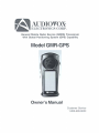
With Global Positioning System (GPS) Capability
Model GMR-GPS
Owner's Manual
Customer Service
1-800·290·6650
INDEX
Warning ..............................................................................................................................................
Caution
..............................................................................................................................................
General Mobile Radio Service (GMAS) Ucense ....................................................................................
General Features ...................................................................................................................................
The Global Positioning System (GPS) Network ....................................................................................
The GPS Receiver ..................................................................................................................................
TheGMR-GPSUnit .................................................................................................................................
GeHing to Know Your GMR-GPS Unit .....................................................................................................
Operational Status Icon Definition .........................................................................................................
Accessories ............................................................................................................................................
Powering the GMR-GPS Unit .................................................................................................................
Installing the BaHeries ...........................................................................................................................
Using Rechargeable Batteries or Vehicle CigareHe Ughter BaHery Eliminator .................................
Operational Modes .................................................................................................................................
GMR·GPS Gateway Page Access to the Menu Pages ..........................................................................
Scrolling Through the Menu Pages .......................................................................................................
GMR-GPS Operational Menu Flow Diagrams (Figures 1-5) .................................................................
SeHing Up the GMR-GPS Unit ................................................................................................................
Adjusting the Volume ..............................................................................................................................
SeHing Up the GPS Feature ...................................................................................................................
Paging Through GPS Functions ............................................................................................................
Initializing the Global Positioning System Mode ....................................................................................
Selecting Pages .....................................................................................................................................
Standby Pages .......................................................................................................................................
GPS + Radio Standby Page ...................................................................................................................
GPS Only Standby Page .........................................................................................................................
Radio Only Standby Page ......................................................................................................................
The Gateway Page .................................................................................................................................
Hot Key Menu Access .............................................................................................................................
The Navigation Page ..............................................................................................................................
The Mark Waypoint Page ........................................................................................................................
The MAP Page ........................................................................................................................................
The POINTER Page ...............................................................................................................................
The GPS MENU Page ...........................................................................................................................
Taking a Trial Run ..................................................................................................................................
Lers Begin ..............................................................................................................................................
Mark Your Waypoint ................................................................................................................................
Let's Take a Short Trip ............................................................................................................................
Going Home ...........................................................................................................................................
Locating Another GMR-GPS User ..........................................................................................................
GMR·GPS Radio Operation ............................................ .......................................................................
Radio Controls .......................................................................................................................................
Accessing the Radio Setup Parametars ...............................................................................................
Explanation and Use of Radio Setup Functions ....................................................................................
Accessing the Hot Key Radio Operaling Modes ....................................................................................
Explanation of Hot Key Menu Use ..........................................................................................................
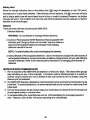
Notes For Good Communication ...........................................................................................................
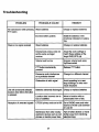
Troubleshooting .....................................................................................................................................
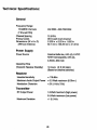
Technical Specifications ..............................................................................................................
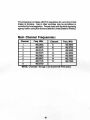
Main Channel Frequencies ....................................................................................................................
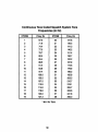
Continuous Tone Coded Squelch System Tone Frequencies (in Hz) ..................................................
Warranty ..............................................................................................................................................
2
3
3
3
4
4
5
5
6
7
8
8
8
9
10
11
12
13
18
19
20
21
21
21
21
22
22
23
23
24
25
26
27
28
30
36
36
36
38
38
39
40
40
41
42
43
44
46
47
48
49
50
51
WARNING:
• The GMR·GP$ shoukS be used as an aid in navigation. The unit is not intended to replace
basic navigational procedures and common sense.
• Because of errors inherent In the nature of the GPS system, the unit will not guide you to an
exact position or the precise Indicated coordinates. However, under most circumstances, il
should be accurate to within about 100 feet.
• When using this device in a vehickl, use It onty when the vehk:1e is stopped and it is safe to do
so. Operating the unit while driving is dangerous and could result in an accident or collision. It
Is more important to keep your eyes on the road and hands on the wheel.
• Do not operate the transceiver unless you are licensed to do so.
• Remove the batteries from the unit if it is not expected to be used for long periods. This will
eliminate the possibitity of chemicals leaking from the battertes and corroding the unit.
• Avoid exposing the unit to water or extremes of temperature.
• Do not use this device in or near a mining facility, which uses remotely triggered explosives
or in areas JabehKt "Blasting Area". Premature or accidental detonation may result.
• 0 0 not attempt to modify or in any way increase the output of this transceiver. Its output is
designed to meet the legal limits set by the FCC.
• 00 not use this device or change its batteries in potentially explosive atmospheres as sparks
in such areas could result in an expklston.
• Tum your transceiver off wherever posted notices restrict the use of radios or cellular
telephones. Facilities such as hospitals may use equipment that is sensitive to RF energy.
• Tum your transceiver off on board aircraft when requested to do so.
• 00 not place your radio in front of a vehicle's air-bag. If the air-bag deploys, it could propel
the unit like a projectile causing bodily injury.
CAUTION:
• Never attempt to charge alkaline or dry cell batteries, as batteries may burst causing personal
Injury and damage to the unit. When recharging batteries, use only Audiovox-approved rechargeabfe batteries and charger. Use of the Audiovox charger with other brands of batteries is
not recommended. As battery charging times will vary with different brands, refer to the
manufacturer's instructions for charging other brands of batteries.
• Keep the antenna at least 1 inch (2.5 cm) away from your head and body when transmitting.
00 not use your GMR-GPS transceiver with a damaged antenna.
• Replace the rubber cover over the headset receptacle when not in use.
General Mobile Radio Service (GMRS) License:
Use of this unit within the United States requires an FCC GMRS license. An individual 18 years
of age or older, who Is not a representataive of a foreign government, is eligible to apply for a
GMRS system license. You will need two forms from the FCC; FCC Form 159 and FCC Form
605 Main Form and Schedule F. You can find the forms online at: http:// www.fcc.gov I
formpage.html, or call 1-800-418-3676.
3
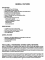
GENERAL FEATURES
GPSFEATURES
•
•
-
128 x 64 Dot Pixel LCD Display
LCD Backlight for Night Operation
Mode IconsforGPS + RADIO. GPS ONLY and RADIO ONLY
8 Parallel Channel Satellite Receiver
GPS Partner Localor (GP LOCATOR)
Stores 10 Routes with Up to 20Waypoinls Each
Provides 5 Tracks
Map and Pointer Displays Provide:
Latitude and Longitude
CurrenVAverageIMaximum Speed
Beamg and Heading
Date and Time
Sunrise and Sunset
GMRS FEATURES
- 15 GMRS Channels (7 Shared FRS)
- 38 Privacy Codes (For Each Main Channel)
- Built-In Hands-Free VOX Capability
- Up to 5-Mile Range
GENERAL FEATURES
• Requires 4 AA Alkaline Batteries or Type NiMH or other type
Rechargeable Batteries (Not Included)
- Foid-Down GMRS Antenna
- Swivel Belt Clip
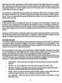
THE GLOBAL POSITIONING SYSTEM (GPS) NETWORK
GPS is a world-wide radio navigation system based on a group of about 26 satellites and their
associated ground stations. A GPS receiver uses signals from the sateJlites to calculate its position
and attitude. The basis of GPS operation is triangulation, and the receiver uses the travel time of
radio signals from the satellites to calculate its distance from each one using a technique called
"pseudoranging". It can then create lines of position.
The satellites transmit two types of signals called "CIA~ (coarse/acquisition) and·PO (precision) . The
latter are encrypted and can only be used by military GPS receivers. As with all other GPS units
available to the public, the GMA-GPS makes use of the CIA signals to establish position and
altitude. The accuracy of a displayed position vanes with a number of factors including time.
4
Generally, the position displayed by a GPS receiver using the CIA signals should by accurate to
within 100 feet, and for 50% of the time it shoUld be accurate to within about 40 feet. It is normal for
the displayed position to "wander" slightly over time. For the same reason, the altitude displayed by
a GPS receiver will also vary slightly.
II is important to understand that such variations are inherent in GPS and do not indicate a fault in
the receiver. Remember also, that GPS is operated by the DOD and is subject to military requirements. There is no guarantee that signals will always be available, or that any displayed poSition or
altitude will be accurate.
THE GPS RECEIVER
A GPS receiver such as the GMR-GPS uses the CIA signals from the satellites to determine its
position on earth. Signals from three satellites are needed to provide an unambiguous position fix,
with reliable attitude indications requiring a fourth. In most circumstances, a GPS receiver will be
able to receive signals from more than four satellites and can decide which it will use to give the best
position.
Signals from GPS satellites are relatively weak and are easily blocked by obstacles or local screen·
ing. GPS receivers may bot work well indoors, in vehicles or underneath trees or foliage. For best
results, the receiver should be able to "see" as much of the sky as possible.
THE GMR-GPS UNIT
The Audiovox GMR-GPS provides you with the features of a precise hand-held GPS unit designed
for general purpose locating and navigation. Not only can it determine your actual position. it can
also guide you to a destination by establishing and storing waypoints to mark the trail or route, and
allow you to return to your original starting point.
But what makes this unit unique, is the incorporation of GMRS capability, whereby your position
can be transmitted to another GMR-GPS unit, thereby allowing another party to know your exact
position, your intended route, and how long it will take you to arrive at that position.
By including three modes of operation, your GMA-GPS can act as a mobile radio transceiver only,
as a GPS unit only or as a combination of the two technologies for navigation and communication
purposes. The GMR-GPS incorporates the following features and capabilities:
•
•
•
•
•
WAYPOINTS: The unit provides 150 waypoints with user-selected names and graphic
symbols.
ROUTE: Lets you navigate up to 10 routes with 20 way points in each route.
TRACKS: Provides an automatic track log using live saved tracks; these tracks allow
the user to locate the beginning and end point of each track.
MARK: Allows the user to save and transmit his/her location to other GMR-GPS units
tuned to the same channel (up to a distance of approximately 5 miles).
GP LOCATOR: Allows the user to receive and store position coordinates of other
GMR-GPS users.
5
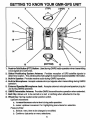
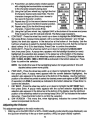
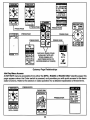
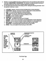
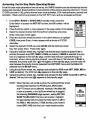
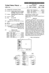
GETTING TO KNOW YOUR GMR-GPS UNIT
(TOP)
3
4
2
1
6
lL-_ _ 7
16-_ _....l
IS---jm1U
o
•
14
13
~12
9
11
1. Push-to-Talk Button (PTT) Button: Used during GMRS radio operation when transmitting
voice signals and call tones.
2. Global Positioning System Antenna: Provides reception of GPS satellite signals to
determine location. The unit should be held upright to maximize received satellite information.
3. Built-In Speaker: Provides receive audio during GMRS operation.
4. Built-In Microphone: Accepts voice/audio input signals when transmitting during GMRS
operation.
5. External Speaker/Microphone Jack: Accepts external microphone/speaker plug for
use during GMRS operation.
6. GMRS Retractable Antenna: Provides GMRS transmiVreceive operation when extended.
7. Belt Clip: Allows unit to be carried on a belt or clothing when attached to the clip.
8. Wheel Key: Spring-loaded center position switch.
Up/Down movement:
a. increase/decrease volume level during radio operation.
b. cursor up/down movement for highlighting menu items for selection.
Press-to-Enter:
a. Selects menu item to be changed or modified.
b. Confirms data entry or menu selections.
6
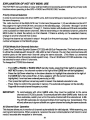
9.
10.
11.
12.
13.
14.
15.
16.
Page BuHon (PAGE): Scrolls sequentially through menu pages in the forward direction,
and also provides access to a shortcut display for easy acquisition of main GPS displays.
BaHery Compartment Cover: Allows access to four AA batteries when removed.
DC6V Jack: It accepts a DC-to-DC vehicle cigarette lighter battery eliminator adapter.
Battery Charging Contacts: Provide in-unit charging of batteries when unit is placed in
charging stand.
LCD Display: Displays the various pages, menus, and modes of operation.
Power OnlOff/Mark BuHon (CYM): Provides a means of tuming the unit on and off;
during GPS operation. this button is also used to mark a current position for save purposes,
or for sending your location to another unit during tracking/GO TO operation.
Monitor (MON) BuHon: Provides a means of temporarily bypassing the squelch setting
and play all signals on a given GMRS channel.
Belt Clip Attachment Stud: Allows unit to be attached to the belt clip.
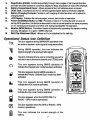
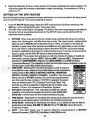
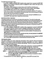
Operational Status Icon Definition
TX
--
--
()
This icon appears during GMRSIQPS operation when
an audio or location radio signal is being transmitted.
During GMRS operation, this icon indicates the
relative strength of a received radio signal.
This icon indicates that a user is contacting you with a
unit that is set to the same channel and CTCSS cod9.
This icon appears during GMRS operation to
indicate the channel scan mode has been activated.
This icon appears during GMRS operation to
indicate the Priority Channel Scan mode has been
activated.
This icon appears during GMRS operation to
indicate the VOX mode is activated.
18
This icon appears during GMRS operation to
indicate the Key Lock mode is activated.
i
This icon appears when the RADIO ONLY or
RADIO + GPS mode is operational.
GPS
This icon appears when the GPS or RADIO + GPS
mode is operational.
00
This icon indicates the current strength of the
battery.
7
Accessories
SPAING
CUPS
SUPPUED:
(1) Belt Clip
(1) Carrying Case (PIN GMRGPS-CS)
SPRING LOADED
BELTCUP
OPTIONAL:
(1) Desktop Charger (PIN GMRGPS-SC) and
AC/DC Wall Adapter (PIN GMRGPS-WA)
(1) Vehicle Cigarette Lighter Battery Eliminator
(DC12V-to-DC 6V) (PIN GMRGPS-BE)
(1) Car Mounting Bracket (PIN GMRGPS-CB)
(1) Headset (PIN FRS-SHSn
(1) Set of Rechargeable Batteries
Belt Clip Accessory
Powering the GMR-GPS Unit:
Your GMR-GPS unit operates on four AA batteries. Alkaline batteries will provide slightly better
performance than rechargeable batteries. Only Audiovox-approved rechargeable batteries can be
recharged in the unit using the optional charger. This will ensure optimum pertormance for the
GMR-GPS. Use of the AudiOvox charger with other brands of batteries is not recommended, as
battery charging times will vary. Refer to the manufacturer's instructions for charging other brands of
batteries.
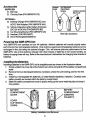
Installing the Balteries:
Installing batteries in the GMR-GPS unit is straightforward as shown in the illustration below.
1. Simply unlatch the cover clip at the bottom rear of the unit and lift off the battery compartment
cover_
2. Remove the four discharged batteries, if present, unless the unit is being used for the first
time.
3. Install four rechargeable AA batteries, or install Alkaline batteries, if desired. Carefully note
battery polarity as marked within the battery compartment.
4. Slide the battery compartment cover in place; swing up the cover retaining clip and snap it
into position.
BATTERY
COMPARTMENT
COVER
.
COVER
CLIP (SWING
DOWN)
Battery Installation and Removal
8
BATTERY
COMPARTMENT
(OBSERVE
POLARITY)
The following guidelines will improve performance and provide longer operating times for the
GMR~GPS unit:
1. Do not mix old and new batteries.
2. The use of alkaline~type batteries is recommended to provide the longest operating time.
3. Do not mix alkaline, standard (carbon~zinc) or rechargeable (NiMH) batteries.
4. If the unit is not to be used for an extended period of time, remove the batteries. Old or
leaking batteries can cause damage to the unit and will void the warranty.
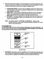
Using Rechargeable Batteries or Vehicle Cigarette Lighter Battery Eliminator:
When rechargeable batteries are installed in the GMR~GPS unit, they can be recharged by placing
the unit on the optional charging stand, Part Number GMRGPS~SC.
CAUTION: The optional charging stand is intended for use only with Audiovox~approved rechargeable
(NiMH) batteries (PIN GMRGPs.Sn. Avoid overcharging the batteries, or else battery
life will be shortened.
In addition, the unit can be operated from a 12 Vdc source (such as available from a car cigarette
lighter receptacle) only by connecting the optional vehicle cigarette lighter battery eliminator to the
DC6V jack on the lower right side of the unit. When connected for operation in this manner, the
batteries are bypassed and are no longer used to power the unit. The battery charge indicator icon
displays the battery charge level.
CAunON: Direct application of 12 Vdc wilt cause damage to the unit.
iii
:
Full Battery - Three segments illuminated.
Low Battery ~ One segment illuminated.
GMR~GPS
INSERT INTO VEHICLE
12 VDC CIGARETTE
I
RECEPTACLE
UNIT
ADAPTER
PLUG
DC6V
JACK
Vehicle Cigarette Lighter Battery Eliminator Setup
9
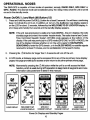
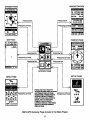
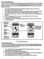
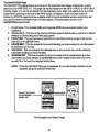
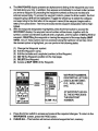
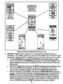
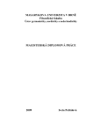
OPERATIONAL MODES
The GMR-GPS is capable of three modes of operation; namely, RADIO ONLY. GPS ONLY or
GPS + RADIO. The desired mode can be selected using the Setup menu once the unit is turned
on and in the standby mode.
Power OIllOff (6) and Mark (M) Button (12)
1. Press and hold the power On/Off (6) button for at least 2 seconds. You will hear a confinning
beep to indicate the unit is on. In addition, at turn-on, the Audiovox logo display appears
on the LCD for about 2 seconds, followed by the WELCOME TO GP LOCATOR display. A
short beep and melody then sounds and the standby display appears.
NOTE: If the unit was previously in a radio only mode (GMRS), the unit displays the radio
standby page and enters the monitor receive mode. The radio channel and Coded
Tone Controlled Squelch System (CTCSS) code appears at the bottom of the
display. If the unit was previously in a GPS mode (GPS ONLY or GPS + RADIO), the
top of the display indicates whether or not the unit is ready for NAVIGATION,
SEARCHING to enter the GPS domain, or in the SLEEP MODE (no satellite signals
received for at least 7 minutes, and no reinitialization of the search mode).
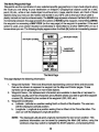
2.
Pressing the c9/M button for longer than 1.5 seconds will tum off the unit.
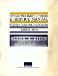
3.
In GPS mode, a Gateway page can be accessed from any of the six primary menu display
pages; this page provides quick access and/or return to any other primary menu page.
NOTE: Momentarily pressing the 6/M button while the unit is on will access the Mark
function, which is used during GPS operation to keep track of waypoints and route
information (discussed later in detail in this manual).
AUDIOUOX
~
AUDIOl'OX
GMRGPS
~~
LOGO DISPLAY
TO
GPlOCATOA
~
e;.
~1
WE1.COMETOGP
LOCATOR DISPLAY
GPSONLY
STANDBY DISPLAY
GPS + RADIO
STANDBY DISPLAY
Power On Displays and Standby Pages
10
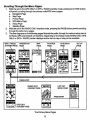
RADIO ONLY
STANDBY DISPLAY
NAVIGATION PAGE
STANDBY PAGE
PRESS ENTER
PRESS ENTER
PRESSJHOLO PAGE
MAP PAGE
,
POINTER PAGE
ENTER
PRESS/HOLD PAGE
PRESSIHOLO PAGE
PRESS
GATBNAY PAGE
SETUP PAGE
MENU PAGE
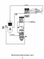
PRESS AND HOLD PAGE TO
ACCESS GATEWAY DISPLAY FROM L===-,--,-:~
Am PAlMARYOISPlAY PAGE;
MOMENTARLY PRESSPAGETO PRESSIHOLD PAGE
ACCESS THE NEXT PRIMARY
DISPLAY PAGE. USE UPIDOWN
WHEEL KEY TO HIGHliGHT
PRIMARY PAGE ICONS ON
GATEWAY DISPLAY; lHEN PRESS
ENTERTOACCESSPRIMARY
DISPLAY PAGE,.
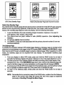
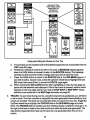
GMR-GPS Gateway Page Access to the Menu Pages
11
GPS
'*
SETUP
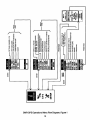
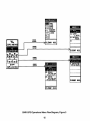
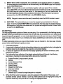
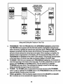
Scrolling Through the Menu Pages:
1. With the unit in the GPS ONLY or GPS + RADIO standby mode, pressing the PAGE button
will permit scrolling through the primary radiO/GPS menu pages.
a. Navigation Page
b. MapPage
c. Pointer Page
d. GPS Menu Page
e. Setup Page
f. Standby Page
2. With the unit in the RADIO ONLY standby mode, pressing the PAGE button permits scrolling
through the radio menu pages.
3. The flow diagrams on the following pages Illustrate the paths through the various setup menus
for Radio, GPS and General unit functions. Depending on the Setup mode (RADIO ONLY, GPS
ONLY or GPS + RADIO) certain displays and/or menus mayor may not be available.
GPS + RADIO
POINTER
NAVIGATION
SETUP
STAt<D,"' PAGE
SETUP
PAESSENTER
RAOIOQNlY
STANDBY PAGE
~!§!~q
HOT KEY
MENU PAGE
~
PAESSENTER
GPSONLY
STANDBY PAGE
The Primary Menu Pages
12
Q
••
ii ~
~
~
.i
c
"
~
~
0
~~ ~
~
Irl
z
!
, 0
,•~
'
<I , ; ~
ffi
0 •
~
~
i
•~ h~
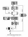
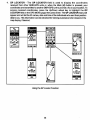
GMR-GPS Operational Menu Flow Diagram, Figure 1
13
~
~
i•
GMR-GPS Operational Menu Flow Diagram, Figure 2
14
.....
.....
.....
GMR·GPS Operational Menu Flow Diagram, Figure 3
15
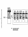
PRESS PAGE
SET DUAL
CI1ANNEL(,.,S)
VOX DELAY 0FFI14 SEC
~g~~~~~ OFFI1-9MB..ODIES
ROOBl BEEPONtOFF
~
PRESS
ENTER
"""'"
TOHOTKEY
MENUS, FIGURE 5
SETUP
"0"
ONLY
~-r"i
FIGURE!
"'ESS
'''''''
GMR-GPS Operational Menu Flow Diagram , Figure 4
16
use
UPIOOWN
WHEEl KEY TO
HIGHUGHT ITEM:
lHEN PRESS ENTER
G)
~
:D
,
-
G)
"
f
COO.' 99
' . .... _ ... w •• _ ... ......,_··
SCAN: OFF
~
~
~
"
f
PRIORITY
CHANNEL
SElECT(I-151
p'~",,_,IJ!!L.,_,
(j)
c'
"-
HUT KlY
ENTER HOT
KEY MENU
CTess
AllCHANNEU
SUBCOOE
DUAL (;HANNEL
SElECT (1-38)
SCAHSElECT
=
ijilX'i'OFF'
......... ,... ,........"......' 1
'
LOCKI OFF
'
~
c
i
0
~'
<C
~
.?
"
'"
,.;'
C
;
NOTE:
THE HOT KEY MENU IS ACCeSSIBLE
FROM BOlH THE GPS + RADIO
STANDBY PAGE AND "THE ROO
(RADIO) ONlY STANDBY PAGE
VOXIAOOE
SElECT
KEY LOCK
ONIOFF
SElECT
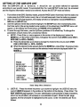
SETTING UP THE GMR-GPS UNIT
After the GMR-GPS unit is turned on. it should be set up and/or tailored for operation
according to user specific needs. To accomplish this, the basic SETUP mode must be accessed
and the required information needs to be entered. Access the SETUP mode as follows:
1.
2.
3.
4.
From either of the GPS Standby modes, press the PAGE button five times (from the radio only
mode press the PAGE button once); the unit should beep each time the button is pressed.
When the SETUP page appears, the display will show a highlighted (boxed) RADIO icon,
GPS icon or SETUP icon.
Use the Up/Down wheel key switch to highlight the SETUP icon; then momentarily press
the Enter switch (the spring-loaded center position of the wheel key); the SETUP menu will
appear on the display as shown below, and MODE will be highlighted.
To scroll through this menu, use the Up/Down positions of the wheel key. To change the
parameters of each menu item, proceed as follows:
a. MODE - Press Enter; a menu appears in the center of the display and, below the
MODE bar, at the bottom of the menu, will appear the current mode (ROO (radio) ONLY,
GPS ONLY or GPS + RADIO).
(1) Press the wheel key up or down to change the mode to the one you want (ROO
ONLY, GPS ONLY or GPS + RADIO).
(2) When the desired mode appears below the MODE bar, press Enter; the popup menu
disappears from the screen and the selected mode remains displayed below the
MODE bar.
PRESS ENTER
TO SELECT
MENU ITEM
FOR CHANGE
PRESS
WHEEL KEY
UPORDOWN
TO SELECT
MENU ITEMS
RADIO ONLY
GPSONLY
GPS+RADIO
Basic Setup Menu Selections
b.
USER 10. - Press the wheel key switch up or down to highlight the USER 10 item; the
current USER 10 appears in the window at the bottom of the display. Press Enter. The
EDIT USER 10 page appears; The user identification code consists of eight characters,
which can be all letters, all numbers ora combination of each. When the edit page
appears, the first character is highlighted by the cursor. Enter the desired user 10 as
follows:
18
(1) Press Enter; an alphanumeric window appears
.OtT
with a highlighted number/letter corresponding
us.", to
" " " 10
to the character presently being used.
(2) Using the UpIOown wheel key. highlight the first
IlUD
~1l.I~E!!.
10 character desired and press Enter. The first
US<
1i"T&A tufTott
character changes and the cursor moves to
TO aolT.
the second character position .
u" .....
lNTTottS TO
(3) Repeat step (2) for the second desired character;
<H_
the cursor moves to the third character position.
SAllE
SAVE
(4) Repeat step (2) for the third through eighth
CANCEL
CANCEL
character, if used; then press Enter.
(5) Using the UplDown wheel key, highlight SAVE at the bottom of the screen and press
Enter to save the user 10 code just entered. The Setup page reappears.
c. CONTRAST - Press the wheel key switch upor down to highltght the CONTRAST item;
then press Enter. A popup menu appears with a contrast level between 1 and 10 high
lighted; the level also appears in the status bar at the bottom of the display. Use the
Up/Down wheel key to select the desired display contrast for the LCD. Set the contrast at
about halfway (4 or 5) for best display. Press Enter to confirm the selection.
d. BACKLIGHT - Press the wheel key switch up or down to highlight the BACKLIGHT
item; then press Enter. A popup menu appears with the backlight duration (or none)
highlighted; the selection also appears in the status bar at the bottom of the display.
Use the Up/Down position of the wheel key switch 10 select thelCO backlight feature
OFF. 15 SEC. lOSEC. 1M1N or STAY ON as indicated in the bottom status bar. Press
Enter to confirm the se~ion.
N01'E; Be mindful that use 01 the backlighting feature for longer periods of time will
deplete battery power more quickly.
e. PWR SAVE - Press the wheel key switch up or down to highlight the PWA SAVE item;
then press Enter. A popup menu appears with the current selection highlighted; the
selection also appears in the status bar at the bottom of the display. Use the Up/Down
position of the wheel key switch to select the desired power save option at OFF, SHORT
(3 seconds) or LONG (5 seconds) as indicated in the bottom status bar. Press Enter to
confirm the selection.
f. KEY BEEP - Press the wheel key switch up or down to hlghltght the KEY BEEP item;
then press Enter. A popup menu appears with the current selection htghltghted; the
selection also appears in the status bar at the bottom of the di~ay. Use the Up/Oown
position of the wheel key switch to tum the key beep ON or OFF as indicated in the bottom
status bar. Press the Enter button to confirm the selection.
g. 8m VERSION - This menu line, when highlighted, indicates the current SoftWare
version incorporated into the unit.
Adjusting the Volume:
This adjustment applies to the radio modes only.
1. With the unit in the RDO ONLY or GPS + RADIO standby mode (standby page displayed), use
the Up/Oown wheel key in the up or down position; a VOL bar graph display appears.
19
2.
Move the wheel key in the up or down position to increase or decrease the volume setting. The
volume bar graph will increase or decrease in steps, accordingly, to a maximum of 16 or a
minimum of 1.
SETTING UP THE GPS FEATURE
Now that the basic setup procedures have been performed, you must now perform the setup procedure for the GPS feature. This is accomplished as follows:
1. From the SETUP display page, select the GPS mode using the Up/Down wheel key; the
GPS icon will be highlighted (boxed). Then press Enter.
2. The GPS menu shown below will appear. The items in this menu are accessed and edited in
the same manner as explained previously for the SETUP menu; use the Up/DownlEnter
wheel key switch as before.
a. DATUMS - Since maps and charts are created using a starting reference point called a
datum, this starting point will differ from map-to-map. The most common mathematical
ellipsoid used is WGS.a4 (World Geodetic System 1984). In addition to the WGS-84
standard, a great many other datums are available for entry depending on user location.
If you use maps or charts specifying a datum other than WGS-84, you should change
the datum applicable to that region to reduce position errors. If you are not sure of which
datum to apply, use the WGS-84 datum for bast overall performance.
b. LOCATION - The Location item provides you with four choices for display of positional
information; namely. Degrees (DODO). Minutes (MM'), Seconds (SS"), Degrees and
Minutes only (DDD'MM.MM'), Degrees only (DDD.DDDDD') or a UTM (Universal
Transverse Mercator). The capability to adjust the time offset value is available under the
OTHER option of !he TIME ZONE lunction below.
c. TIME ZONE - Selecting the Time Zone provides you with a choice of
the available zones relative to the United States and its possessions.
These oonsist 01 ATLANTIC, EASTERN, CENTRAL, MOUNTAIN,
PACIFIC, ALASKA, HAWAII and SAMOA. In addition, Time Zone also
offers a choice of OTHER, whereby the unit can be programmed for
any other specific area not listed. If OTHER is selected, the param
eters are entered under UTC (UniVersal Time Clock) Offset. This
provides you with the capability of adjusting the Time Offset value
between +12 and -12 in reference to Greenwich, England.
d. DAYLIGHT (SavingTime) - This menu item provides you with the
capability of choosing the daylight saving time mode {SAVe OFFI
SAVE ON). In either case, the time must be entered manually.
e. TIME MODE ~ Selecting the Time Mode item allows you to select the way the time is
presented on the display (either 12 HOURS or 24 HOURS clock format).
1. DATE MODE - Selecting the Date Mode item allows you to select the way the date is
presented on the display (OD-MM-YV, MM-DI).YV, or YV·MM-DD), where M=monlh,
D=day and Y=year.
g. UNIT ~ This item allows you to specify distance measurements in METRIC
(Meters/Kilometers) , STATUTe (Feet/Miles) or NAUTICAL units.
20
PAGING THROUGH GPS FUNCTIONS
INITIALIZING THE GLOBAL POSITIONING SYSTEM MODE
Before using the GPS mode of your GMR-GPS unit for the first time, the GPS receiver needs to
automatically determine its location. To initialize the GPS receiver, proceed as follows:
WATCHING SATELLITE ACQUISITION ON THE GPS STANDBY!STATUS PAGES
Your GMR-GPS unit operates on positional data acquired from NAVSTAR satellites. To introduce
your unit to this information:
1. Find a large, relatively open area that provides a clear view of the sky, with a minimum of
2.
3.
obstructions, such as buildin9s, radio towers, etc.
Press and hold the Power (C) )/Mark (M) button on the left side of the unit for at least 2
seconds.
A beep and melody will sound and the standby screen will appear on the LCD. If the unit is
being turned on for the first time, the standby screen will default to the RADIO + GPS mode,
or it will reflect the standby screen for the mode previously used.
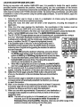
The GMR-GPS unit needs to receive at least three strong satellite signals to find your location.
The standby page graphically shows the unit acquiring satellites as the satellite icons around the
globe circumference become animated and darken. SEARCHING appears under the 10 bar at the top
of the display. When you see NAVIGATION appear, your GMR-GPS has found your location and you
are ready to use all of its GPS capabilities.
4.
If the unit is ready for NAVIGATION, each of the satellites providing
current GPS user location should be highlighted, and should equal or
exceed 3 as shown around the circumference of the globe icon (4 or more
is preferable). If the unit is SEARCHING, wait approximately 5 minutes
for the satellite(s) to find your position. The NAVIGATION indication should
appear. Thereafter, during subsequent GPS operation, acquisition time
should only take from 5 to 45 seconds. If satellite acquisition does not
occur within approximately 7 minutes, a message appears indicating the
signal has been lost and asking whether or not you wish to initialize the
unit again. It NO is your option, the unit will indicate SLEEP MODE on the
GPS + RADIO and GPS ONLY standby page. Press the PIT button to
re-enter the SEARCHING mode. It YES is your option, the unit will re-enter
- MESSHGE
SfIITELUTI!
SIGHAL. HRS
lEEN LOS'.
DO 'IOU
WAHT TO
DlITIALIIE
IT l'
L_-"
the SEARCHING mode.
SELECTING PAGES
As described earlier, the information needed to operate your GMR-GPS is contained on six main
pages; namely, the Standby page, Navigation page, Map page, Pointer page, GPS Menu page and
Setup page. To scroll through the pages, simply press the PAGE button. Depending upon the Mode
selected, as explained previously, there can be three different Standby pages. The following discussion describes the three types of standby pages, plus the other five pages.
STANDBY PAGES
There can be three different Standby pages, each dependent on the Mode selected using the Setup
page.
21
GPS + RtJdlo Standby Page
The GPS + RADIO Standby page automatically appears as the default page if the unit is being
turned on for the first time, or if it ls selected as the operational mode using the SETUP page. In
additoo to depicting satellite acquisition (SEARCHINGlNAVIGATION), this page also displays the
foJlowing Information:
1. A user identification (I D) code consisting of eight characters maximum. If no user ID
code appears, refer to basic setup mode.
2. The number of acquired satellites. (This could fluctuate depending on clear-sky conditions
or the relative position of the unit's GPS antenna as it is carried or transported.)
3. The volume level bar graph relative to radio (GMRS) operation. (See Adjusting the
Volume.)
4. The current time, either on a 12..tlour or 24-hour basis (refer to SETUP mode) .
5. The primary GMRS channel number.
6. The GMRS CTCSS sub-code assoclated with the primary channel number (if one was
previously selected).
SEARCHING!NAVIGATION
SATEWTE
ACQUISITlON
STATUS
lJSEJ\
VENTlFKOAllON
(ID)COOE
16-STEPVOlUME
BAR GRAPH (USE
UPJ1X)WNWHEEL
KEY TOAOJUSl)
OJRRENTllME
(12 OR 24
_--,,-,::.:
HOUR FORMAT)
GPS + Radio Sl8nc1)y Page
GPS Only SIJJndby PIIfI"
The GPS ONLY Standby page can be se~ed from the SETUP page using the MODE function
as previously explained. In addition to depicting satellite acquisition (SEARCHINGlNAVtGATION).
this page displays the following information:
1. A user identification (ID) code consisting of eight characters maximum. If no user ID
code appears, refer to basic setup mode.
2. The number of acquired satellites as discussed before.
3. The current date in the format selected from the GPS SETUP menu (DATE FORMAn: th is
format can appear as DD-MM-vy, MM-DD-YY or YY-MM-OO.
4. The current time, either on a 12.ohour or 24-hour basis (refer to SETUP mode).
22
,'-''''''''''
UP""'""""
WHEEL KEY
GPS Only Standby Page
Radio Only Standby Page and Volume Function
Radio Only Standby Page
The RADIO ONLY Standby page (shown above) can be selected from the SETUP page using the
MODE function as prevlousty explained. Unlike the other two modes which include the GPS
feature, this stam:lJy page depicts a radio only display with the frnJowing infonnation:
, . A user identification (ID) code consisting of eight characters maximum. If no user ID
code appears, refer to basic setup mode.
2. The volume level bar graph relative to radio (GMRS) operation. (See Adjusting the
Volume.)
3. The primary GMAS channel number.
4. The GMRS CTCSS sub-code associated with the primary channel number (if one was
previously selected).
nr. Gateway Pllge
To simplify the transition between GPS-related page displays, a Gateway page Is provided which
allows you to jump between main pages in the GPS modes (GPS + RADIO and GPS ONLY), rather
than have to scroll through unrelated pages to acquire a desired page. When operating in a GPS
mode, the Gateway page can be acquired from any display. To accomplish Gateway page
acquisition:
1. From any display in either GPS mode, press and hold the PAGE button for at least 2
seconds; the Gateway display will appear, offering anyone of six page selections to go to.
2. The title at the top of the Gateway display will differ according to the mode display it was
accessed from; e.g., if the GPS MENU page was in use, a jump to the Gateway page will
resutt in the Menu page icon being highlighted. and the page title will change to MENU.
3. To access any of the six GPS menu pages from the Gateway page, use the UpIDown wheet
key to highlight the desired page icon; then press Enter to access the page.
4. To return to the Gateway page, simply press and hold the PAGE button for at least 2
seconds.
NOTE: Remember that a momentary press of the PAGE button, whether from the Gateway
page or the current main page will access the next menu page as explained
previously in Scrolling Through the Menu P~•.
23
,
GAT~AY PAGE ICONS
(HIGtiUGtfTwrrHUPI
OOWNWHEEL KEY
ANOPRESS ENTERlO
ACCESS DISPlAY PAGES)
Gateway Page Relationships
Hot Key MMru Access
A HOT KEY menu is accessible from either the GPS + RADIO or RADIO ONLY standby page; this
page appears when the Enter switch is pressed, and provides you with quick access to the basic
radio functions. Refer to the section on radio operation for a detailed explanation of these items.
RADIO ONlY
GPS+RADK>
24
The NAVIGATION Page
The NAVIGATION page presents a summary althe important parameters entered into. oreampuled by your GMA·GPS unit. This page can be accessed from the GPS + RADIO or GPS ONLY
standby pages, or it can be accessed from the Gateway menu whtch is available 'rom any of the
pages when operating in the one of the GPS modes. In addition, when the Enter button is
pressed, a STATUS page becomes available which shows the sat~lit9 number acquired by the
unit, and the relative strength of each of these signals. The parameters shown on the
NAVIGATlON page include:
1. Coordinates· The Latitude (N/S) and Longitude (E/W) of your present position are
2.
displayed.
Altitude (ALT) • This line of the display indicates present altitude above sea level in Metric
(Meters) Of StatuteINautical (Feet) equivalents.
3. DATEITIME - The next two lines present the current date and time-of-day in the format
entered into the SETUP menu.
4. HDGJSPEED - This line presents the current heading you are traveling on, and the speed
at which you are moving.
5. TRIP/ODO - This line presents the elapsed time of your current trip, and the distance
(odometer reading) you have traveled.
6. SUNRISE/SET - This line presents the time of sunrise and of sunset based upon the
Information you have entered in the SETUP menu with respect to the time zone, time
format (12 or24 hour) and daylight saving time.
NOTE: When the NAVIGATION page is displayed, the overall display contrast can be
adjusted using the UpJOown wh ..1key.
The Navigation and Status Pages
25
The Mark (Waypolnt) Page
Waypoints are the coordinates of user-selected specific geographical or man-made objects along
the route you are taking to your destination or endpoint. Geographical objects could be a lake,
pond, hill, etc .• while a man-made object could be a bam, house, electric tower, etc. Each of these
objects along your way can be marked and stored in your GPS unit so that your return path is
plainly marked and can be retraced easily. The MARK page appears whenever the Mark (M) button is
momentarily pressed; this page presents the options of SAVEing the waypoint, transmitting (SEND)
the waypoint or accessing a MAP VIEW (on the map page) of the waypoint in question. If the send
option is used, your present location (coordinates) is transmitted to another GMR-GPS unit so it
knows where you are. The following display appears when the Mark (M) button is momentarily pressed:
MflRK
WAYPOINT NAME
}
WAYPOINT
COORDINATES
The Mark Page
The page displays the following information:
1. Waypoint Symbols - There are 38 symbols representing common items and structures
that can be chosen to represent a waypoint on the Map and Pointer pages. These
symbols can be geographic or man-made objects.
2. Waypoint Name - Six alphanumeric characters are available to describe or represent a
waypoint; usually, just three characters are sufficient unless you wish to give the waypoint
a name (ID), followed by the number of the waypoint (001,002, etc.).
3. Waypoint Coordinates:
a. latitude - latitude is a position resting North or South of the Equator. The user can
edit the displayed latitude position.
b. longitude - longitude is a position resting East or West of the Prime Meridian. The
user can edit the displayed longitude position.
NOTE: The displayed latitude and Longitude represents the last known position. This
positional information can be saved by pressing the Mark (M) button, using the
Up/Down wheel key switch to highlight the SAVE selection, and pressing Enter.
26
SAVE ~ When SAVE is highlighted, the coordinates can be saved in memory. In addition,
the saved waypoint coordinates can be retrieved using the GPS MENU page and highltght~
4.
ing the WAYPOtNTS r..ld .
SEND ~ To transmit thecurrenl coordinates, together with user (your) 10, to a remote
user GMR-GPS unit tuned to the same channel (and
sub-code), simply highlight
the SEND field and press the Enter switch. At the receiving unit, a loud special tone will
be heard signifying receipt of the coordinate information. This information can also be
accessed from the GP LOCATOR field in the GPS MENU display.
5.
crcss
NOTE: Waypoint names cannot be sent (transmitted) when the SEND function is used.
6. MAP VIEW ~ This option allows you to view the waypoint you just entered on the map
page . To do this, highlight MAP VIEW and press Enter; the map page will appear showing
the waypoint at the given coordinates with its symbol and waypoint number. Press PAGE
to return to the MARK page.
The MAP PlIfIO
The map page presents a picture of where you are going. You, represented by the flashing square,
proceed toward your destination and leave a trail, or track log. As you travel, you can make use of
way points (specific geographic or man-made objects) that can mark your route as you travel. These
waypoints also make it easy for you to retrace your steps, establishing a route back to your starting
point.
To better appreciate where you are and the direction you are headed In. the map page includes
several other useful features to guide your way:
1. A Compass indicator.
2. A map scale is displayed indicating the relative distance in user-selected units; just toggle the
Up/Oown wheel key to adjust the map scale for a convenient display.
3. A status bar appears at the bottom of the display signifying the amount of memory used
between 0 and 100%.
4. Two Information bars at the top of the display automatically scroll through the following
parameters, changing the data presentation about every 3 seconds:
a. Present Position (Longitude and Latitude)
b. Altitude
c. CurrentDateandTime
d. Heading (HOG)
e. Speed of travel
Overall Trip (TRIP) time
f.
g. Odometer (ODO)
h.
i.
Bearing (BRG)
Distance (DSn traveled to target (waYlX>int or endpoint)
5. When the Enter switch is pressed, a sub~menu appears in the center of this screen , and
provides several options related to your trip; these options can be highlighted using the
UpIOown wheel key; then press Enter to change the htghUghted data:
CURRENT LONGITUDE
CURRENT LATITUDE
MAP PAGE
SUB·MENU
MAP SCALE
AJ.TITUlE
CURRENT TIME
HEADING
TRAVELSPEED
TRIP TIME
000 (ODOMETER)
BEARING
DISTANCE
ANIMATED
BOX SYMBOL
TRUE NORTH
POINTER
PERCEN T _ _
MEMOA.Y
----j"";;;:I3
(YOU) OR
r-,-;:..:.:::..:...,.,
QUESTION
MARK (LOSS
OF TRACK)
USED BAR
The Map Page
a.
AHEADINORTHWARD?· When this item is highlighted, press Enter to orient the top
a the map display with respect to waypoints or targets ahead of your intended track,
or with respect to True North.
b.
c.
d.
e.
AUTO/MANUAL ZOOM?· When this item is highlighted, press Enter to select the
display scale Automatic or Manual zoom function.
SYMBOLS ON/OFF?· When this item is highlighted, press Enter to tum the display
symbols ON or OFF.
SAVE TRIP? • When this item is highlighted, press Enter to store a particular trip in
the GPS TRACKS function .
NEW TRIP? • When this item is highlighted, press Enter to erase previous trip data.
NOTE: Two additional options -- STOP NAV? and SKIP WPT? -- appear on this submenu during the trip. The SKIP WPT? function appears on the map display when
It is accessed from the ROUTES menu during the GPS GO ALONG mode
function. This enables you to skip a waypoint in the route; B.g., go directly from
waypoint C to E in the route, thereby skipping waypoint D. STOP NAV? will
terminate the trip along the chosen route, and is availab~ during navigaUon
trackback and go to operaUon in the GPS waypolnt, track and GP k>cator modes.
The POINTER PIIge
When you are moving, with no particular endpoint or target destination, the pointer page will show
you in which direction you are moving, and at what speed. If you are traveling to a specific endpoint
or destination, the pointer page will then show you the name of the location, the distance to the
loeation, and the time it will take to get there. The pointer page displays the following information:
1. A Compass Rose with large central directional arrow Indicates the direction you are going
in.
28
2.
3.
Whether or not the satellite information is sufficient for the unit to provide accurate positional
Information (SEARCHING or NAVIGATION). The indication provides the level of accuracy of
the position based upon the number of satellite signals being received.
An information bar at the bottom of the display pennits vtewing the following parameters when
the UplDown wheel key is used:
a. LATITUDE - Degrees, minutes and seconds (dependent on setup selections).
b. LONGITUDE - Degrees, minutes and seconds (dependent on setup selections).
c. DATE - The current date (dependent on setup selection)
d. TIME - Hours and minutes (dependent on setup selection).
e. ALTITUDE - :Your altitude above sea level in Meters or Feet.
f. HEADING - Current heading In degrees.
g. ODOMETER· The distance traveled.
h. TRIP TIME· The elapsed time since your trip began.
i. SUNRISE - Time in hours and minutes of sunrise (dependent on setup selecUons) .
j. SUNSET - Time in hours and minutes of sunset (dependent on setup selections) .
k. MAX. SPEED - The maximum speed traveled since last trip reset in MPH.
I. AVG SPEED - The average speed of travel during your trip in MPH.
m. SPEED - The current speed of travel during your trip in MPH.
NUMBEROF
SATBllTES
LA111VOE
• celMP,'SS ROSE
IW)PONTER
LONOIT\JOE
DATE
ThE
AL1TfUOE
HEADING
ooa.oETER
TRP1J,£
SLN1ISE
PRESSENTER
Sl-"SET
MAXSPEED
AVGSPEED
Sfm)
The Pointer Page
29
4.
When the Enter switch is pressed, a sub-menu appears in the center of this screen, and
provides several options related to your trip; these options can be highlighted using the
Up/Down wheel key; then press Enter to change the highlighted data:
a.
b.
c.
AHEAD/NORTHWARD? - When this item is highlighted, press Enter to orient the top
a the map display with respect to waypoints or targets ahead of your intended track,
or with respect to True North.
RESET TRIP? - When this item is highlighted, press Enter to clear an existing trip
function, such as average speed, maximum speed, odometer, trip time, etc. The
graphic representation of the trip remains, but all other counters are reset.
INITIALIZE? - If you have relocated more than SOO miles since last using the unit,
this option, when highlighted, allows you to initialize the unit so it can receive new
location and speed data.
N01E: Two additional options -- STOP NAV? and SKIP WPT? -- appear on this
submenu during the trip as a result of Waypoint Marking, Trackback, GP Locator
and Go Along mode functions.
The GPS MENU Page
The GPS MENU page provides you with the means of navigating to your chosen destination. The
GPS menu page includes four selection fields; WAYPOINTS, ROUTES, TRACKS and GP LOCATOR.
The desired field is selected using the Up/Oown wheel key.
WAYPOINTS
FIEiD
ROUTES
FElD
r--_ GPLOCATQR
FlBD
GPS Menu Page
1.
WAYPOINTS - Waypoints are specific geographical or man-made objects along the route
you are taking to your destination or endpoint. To retrieve a waYpOint, toggle the Up/Down
wheel key switch to highlight the WAYPOINTS field; then press the Enter switch.
a.
b.
The WAYPOINTS display presents an alphanumeric listing of the waypoints you have
marked along your trip. In addition. they appear automatically in numeric order (unless
you enter a waypoint ID preceding the waypoint number) as they are marked and
entered sequentially. To access the waypoint column, press the Enter switch; the first
waypoint group (0-9) will be highlighted. Toggle the wheel key to select the category
corresponding to the first letter of the waypoint name (if the waypoint begins with a
letter); then press Enter. The first previously stored waypoint designation will be highlighted.
With the waypoint designation highlighted, press the Enter button to access the
WAYPOINT display; the waypoint name/number will be shown, together with its
symbol, location coordinates (Latitude and Longitude), and the option of GOing TO that
waypoint, DELETEing the waypoint orviewing the waypoint of the map display (MAP
VIEW). Anyof these options can be accessed using the Up/Down wheel key; when
the desired option is highlighted, you can perform the following tasks:
Change the Waypoint symbol.
Edit the Waypoint name.
Edit the Latitude and Longitude (position) of the Waypoint.
GO TO the Waypoint position on the map page.
(5) DELETE the Waypoint.
(6) Access a MAP VIEW of the Waypoint.
(1)
(2)
(3)
(4)
WAYPOINTNUMBERS.
DESCRIPTIVE LETTERS
CAN ALSO BE USED;
E.G., WPOt, WP02,
ETC.
(IFWAYPOINT HAS AN
10, THE 10 PRECEDES
THEWAYPOINT
NUMBER)
press the Enter switch to access and make all the required changes. To return to the
WAYPOINTS screen, press the PAGE button.
d. CLEAR ALL - This function will remove all stored waypoints from memory.
c.
31
HIGt-LOfT ITEM;
lHENPRESSENTER
PRES$PAGElO
REnI'lNlO
WAYPOINT PAGE
00
'w
-, "
~.
~~
IIIII~O tMM
.~
UPJDGIin
g'f
TO 01.....
Using and Editing the Waypoints During Your Trip
2. ROUTES - Routes consist 01 at least two or more way points that define a path to a
destination . This feature guides you from the first waypoint in the route to each
succ essive waypoint until you complete your trip, You can store up to 10 routes.
• . From the GPS MENU page, nlghligntlne ROUTES field using Ille UpIDown wheel
key; then press Enter. The ROUTES display appears with route (01) htghlighted. Th is
display depicts the name and travel distance 01 route 1; each route can contain up to
20 waypoints.
b. With route 01 highlighted, press Enter; the ROUTE display appears showing the name
of the route (TRIP) and the waypoints (A, B, C, etc.) making up the route. You
can now insert or delete a waypoint in the route by highlighting the desired field.
c. When the A waypoint is highlighted, press Enter; the INSERT/DELETE popup menu
appears. Use the Up/Down wheel key to select the desired action and press Enter; If
INSERT is chosen, the display reverts to the WAYPOINTS display which lists the
waypoints in that route. Use the UpIDown wheel key and Enter switch to select the
desired waypoint for incluston In the route you are working on. The display w ill then
return to the ROUTE display. If DELETE is selected, the waypoint is deleted.
:J2
HIGHUGHT ITEM;
THEN PRess ENTER.
PRESS PAG E TO
RETURN TO
RQUTES PAGE
-
_.
"-.~ ,
"w.
\J
II'f llCWl e'T
,,~
Using and Edttlng the Routes on Your Trip
d. This process can be repeated ootil all the desired waypoints are incorporated into the
TRIP route (01) page.
8. Whenever a change is made to an item in the routa. a MESSAGE display appears
when the PAGE button is pressed to return to the ROUTES display. The message
reminds you that you have made a change and if you want to save the route.
t.
Press the PAGE button to retum to the ROUTES field of the GPS MENU page or, if
you wish to edit a second route, press the Up/Down wheel key to highlight the next
(02) route; then press Enter to access the ROUTE page again.
g. When choosing the GO ALONG function after highlighting a route, the map page appears with the selected route displayed. Hthe Enter button is pressed, another menu
appears on the map page asking if you wish to STOP NAV? or SKIP WPT? These
selections are explained in the MAP Page discussion on page 28.
3. TRACKS· As you travel during your trip. using the waypoints as guideposts, you will leave
a trail or track. The track consists of waypoints that were generated automatically by your
unit as you traveled. This track can be used later when you return from your trip. Toggle the
Up/Down wheel key to highlight the TRACKS field on the GPS MENU page and press
Enter. The TRACKS field can contain up to five individual tracks numbered 1 through 5. To
the right of the track number i~ the date and time at which the track was generated. The
data points (waypoints) that make up the track are only generated when the unit ls In
motion.
I«H..l3HT ITEM;
1>1EN PRESS ENTER
PRESSPAGETO
PETURNTO
TRACKS PAGE
Using and Editing the Tracks on Your Trip
a.
TRACKBACK - With the TRACKS field of the GPS MENU highlighted, press Enter,
The TRACKS menu appears with the first track position highlighted. Using the Up!
DoY.fI wheel key, highlight the desired track and press Enter. TRACK LOG LOADING
appears momentarily and the memory bar at the top of the screen indicates the
percent of track data points remaining to be loaded. When loading is complete, the
selected track is regenerated on the display, with the appropriate data points, and
TRACKBACK is highlighted at the bottom of the display. This pictorial representation
of the track does not contain any data coordinates related to the MAP page.
b. TO BEGIN - With the track displayed and TRACKBACK hig1lighted, tt is possible to
VMtw the beginning of the track on the map page. To do this, press Enter; a menu will
appear with TO BEGIN and TO END options. Use the wheel key 10 highlight
TO BEGIN and press Enter. This wincause the display 10 revert to the map page,
which will identify the beginning point of the track.
c. TO END - The TO END option is executed in the same manner as the TO BEGIN
option in step b; highlight the TO END option in the TRACKBACK mode, and the map
page will identify the end point of the track.
d. Track Log Option. - Wamlng displays appear whenever the DELETE and CLEAR
ALL functionS are to be executed with respect to the track log.
34
4.
GP LOCATOR - The GP LOCATOR field is used to display the coordinates
received from other GMR-GPS units or, when the Mark (M) button is pressed, your
coordinates are transmitted to another GMR-GPS unit to provide a fix on your location. To
access received coordinates, press the Up/Down wheel key to highlight the GP
LOCATOR field on the GPS MENU page; then press Enter. The GP LOCATOR menu will
appear and will list the 10 names, date and time of the individuals who sent their position
data to you. This information can be extracted for viewing purposes and/or viewed on the
map display, if desired.
Using the GP Locator Function
35
TAKING A TRIAL RUN
Now that you are familiar with the GPS page features and what functions they convey, it's time to
take a short trip to test your navigation skills. You'll need a relatively open area to perform this
exercise. Let's begin by marking your current location; this can be considered a waypoint, so it can
be used to guide you to your starting point on your return trip.
LET'S BEGIN
To begin with, let's mark your current location as a waypoint.
NOTE: The GMR-GPS unit must be in the NAVIGATION mode (satellites acquired) before you
begin your trial run.
MARK YOUR WAYPOINT
Mark your current position as follows:
1. Make sure all desired parameters for your trip are arranged using the
SETUP menu.
2. Press the Mark (M) button; the MARK (WAYPOINT) page
appears. Since the GMR-GPS unit has now fixed your location, the
display will show a default mark of 001, followed by the coordinates
specifying your initial position.
3. Highlight the SAVE field and press Enter.
To make your trip more enjoyable, let's give your initial position a
more descriptive symbol and name before you commence your trip.
4. To Change the Location Symbol:
a. With the MARK (WAVPOINT) page displayed, use the Up!Down
wheel key to highlight (box) the position symbol; then press
the Enter button.
b. The Symbols screen appears with the current symbol
highlighted.
c. Scroll through the symbols using the Up/Down wheel key
and select one that more closely describes your
location. Then press Enter. The MARK display reappears with
the new symbol adjacent to the location name.
d. Highlight the SAVE field and press Enter; the MARK
screen reappears.
...
"
5. To Change the Location Name:
a.
On the MARK screen, use the Up/Down wheel key switch
to highlight the waypoint name (001,002, etc.) adjacent
to the symbol just changed; then press Enter. The alphanumeric
EDIT WAYPOINT NAME screen appears with the first
character of the location name highlighted.
c. Scroll through the alphanumeric listing using the Up/Down
wheel key, and create a name (no more than 6 characters),
such as HOME01 or HOTEL 1, entering each
character (pressing Enter) as it is selected.
d. When the new name is complete, highlight SAVE and press
Enter. The MARK page appears and shows the
renamed initial waypoint next to the new symbol.
g. Highlight the SAVE field and press Enter; the MARK
screen reappears. Your new starting symbol and waypoint
name are now stored in GMR·GPS memory.
h. Press PAGE to return to the GPS MENU page.
6. To Change the Waypolnt Location:
a. On the MARK screen, use the Up/Down wheel key switch
EDIT
to highlight the Latitude and Longitude indication below the waypoint
LOC"-TIOH
name you just changed; then press Enter.
~. 37-29'80
b. The EDIT LOCATION display appears with the North or South letter
EIE:rOO'38
highlighted.
·_·..._MM
M_._
c. To change North to South and vice-versa, press Enter; a menu
HTBI MlnOM
TO .on.
appears with N or S highlighted (boxed). Use the Up/Down wheel key
to select the desired Latitude and press Enter. The first degree
IUTToru TO
CHIIHlle
position is highlighted.
SlftVE
d. To change the degrees, minutes and seconds information,
CArIICEL
press the Up/Down wheel key in the down position to scroll from
left-to-right, or press the wheel key in the up position to scroll from
right-to-Ieft, respectively. As each position is highlighted, press Enter
to select the value in question (a menu appears) as explained in step c.
e. After a value is changed, press Enter to address the next character,
then press Enter again to access the character for change.
f. Repeat this procedure to change the Latitude, then the longitude,
if desired.
"'"
"'".....
g.
To save the changes, highlight SAVE and press Enter; the new
latitude and longitude specifying your location are stored
in memory; to cancel the changes, htgh light CANCEL and press Enter.
LETS TAKE A SHORT TRIP
Now that the unit knows where you are, press the PAGE bunon to access
the Map page, and lefs take a short trip.
1.
Making sure the unit is ready to navigate (satellites acquired), walk at a
leisurely pace in astraight tine for at least 30 to 50 feet, while observing
the Map page. Approximately 6 to 10 seconds are required for the
compass direction to stabilize.
2. Your immediate location is mimicked by the box icon in the center
of the display; as you walk aklng, watch the icon proceed
along the track line. referred to as a track. This tine
represents the path you have covered.
3. Now take 8 right tum. At this point, you can mark your position (press
the Mark (M) bunon). thereby entering anotherwaypoint; if you wish,
give this location a suitable name as you've done before, and enter
the point into memory.
4. Walk In this new direction for a few minutes and then stop. Again,
mali< this destination or endpoint in the same manner as before.
Now that you have made this short trip, there are three waypoints marking
your track. Lers retrace your steps back to the starting point using the
GO TO feature and the Pointer page.
GOING HOME
To travel back to your starting location:
1. Access the GPS MENU page and press Enter; the WAYPOINTS
screen appears.
2. On the WAYPOINTS screen, use the Up/Down wheel key switch
to highlight the first lenar or number of the location name;
press Enter again to highlight the starting waypoint name to the
right. Press the PAGE button again to access the WAYPOINT page.
3. On the WAYPOINTpage, GO TO i. highlighted (boxed); pres. Enter.
4. The Map page appears showing the (box icon) and your 10 symbol.
5. Adjust the map scale to enlarge the track; then press the PAGE
bunon to access the Pointer page.
the distance traveled and the destination bearing,
6. TRACKING
appears at the top of the page, while the location (coordinates) appears
at the ~nom . The compass pointer Indicates the direction you must
travel to arrive at the starting point of your trip.
'1.
38
LOCATING ANOTHER GMR-GPS USER
During an excursion with another GMR-GPS user, it is possible to locate this user's position
provided he/she transmits the position , thereby giving you the coordinates of the remote
GMRs-GPS unrt. To transmit and receive the coordinates, both GMR-GPS units must set to same
radio channel number and CTCSS subcode nuni>er. By saving these coordinates, you will be abfe
to establish a route to this position using the pointer page compass. To use this feature, apply the
following example:
1. Allow the other user to travel a route to a destination of choice using the guidelines
established for the trial run outlined previously.
2. Along this route, the other user will enter a few waypolnts, including his endpoint or
destination.
3. When the other user reaches the destination, the coordinates of this location must be
transmitted to your GMR-GPS unit in order for you to locate this position.
4. To transmit this informaUon, the other user must select the waypoint. press the Mark (M)
bunon, highlight SEND and press Enter. The MARK SENDING display appears.
5. The GP LOCATOR page appears on your unrt (receiving unit, accompanied by a unique
tone; the Information displayed Includes the remote unit coordinates
(latitude and Longitude) and the remote user identification (10)
name. In addition, the GO TO legend Is highlighted (boxed).
6. If the Satellite signal is lost prior to the location being sent, a
WARNING screen appears when the MARK button is pressed,
Indicating loss of signal and suggesting the location be entered
and sent manually.
a. Highlight YES using the Up/Oown wheel key, and press Enter;
the MARK page appears with the kx::ation information and the
option of SAVEing or SENDing (highlighted wnh a box) this data.
SENOING RECEIVING
UNrr
UNrr
b, To send the infoonation. press Enter; to save the information,
highlight SAVE and press Enter. The data will be saved in
memory for transmission at a later time.
c . When NO is highlighted and Enter is pressed. the WAYPOINTS
SUb-menu page appears with the waypoint in question highlighted.
7. On the receiving unit, if you press the Enter button, the map page will
appear. indicating the position of the other user relative to your position.
8. Select the Pointer page using the PAGE button; the pointer will
show you the direction to the coordinates that were transmitted to
your unit.
9. Use the pointer page to establ~ a track to this position. The
compass pointer will eventually establish the direction you must go
to reach this location .
10. Walk in the direction of the compass pointer for at least 10 seconds;
the pointer page will not only show you the direction, but witJ also
Indicate the distance and time to reach this destination.
11. When you are within approximately 10 seconds of your destination, a
message screen appears to advise you that you have arrived at your
destination point.
NOTE: The unit will not guide you to the exact spot. or coordinates
indicated. but it will be accurat. to within 10 seconds 01
EsUmated Time 01 Arrival (ETA). Therefore. when you are within range of the
position indicated. start ooking for the other party,
39
GMR·GPS RADIO OPERATION
In addition to its Global Positioning System (GPS) features, the GMR-GPS unit also provides General Mobile Radio SeMce (GMRS) capability as a hand-held radio transceiver. As a GMRS transceiver, the unit pennits radK> operation with features such as Coded Tone Controlled Squelch
Syslem (CTCSS). Voice.()pefaled Transmission (VOX). Dual Channel Scan and Key Loci< capabll·
ity.
But the most unique feature is its capability, while operating in concert with the GPS function , of
transmitting user location (coordinates) , with user identification (10 code), to anotherGMR-GPS unit
operating on the same frequency channel and sub-code with a single press of a button . The
transceiver is operational in the RADIO + GPS and ROO ONLY modes; make sure the GMRS
antenna is deployed for optimum radio operation.
TRANSCEIVER
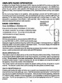
RADIO CONTROLS
ANTENNA
DEPLOYMENT
Po_r OnlOffIM/Jrlc (6 IM) Button (14)
Press and hold the power On/OffIMark (<!:> 1M) button
for at least 2 seconds. You will hear a confirming melody
to indicate the unit is on. To turn the unit off, press and
hold the button for at least 2 seconds.
•
®
Adjusting the Volume
With the unit powered on, and provided the GMR·GPS unit
is in the RDO ONLY or GPS + RADIO mode (standby page
dlsplayed), toggle the UpIDownwheel key switch in the up posrtion to increasevolume, or toggle the
w~ key switch in the down position to decrease volume. The volume dispfay will indicate the
current voh.me level by means of a bar graph.
The Enter function is executed when the wheel key is pressed; this function is used to access
menus, confirm entries andlor edit certain radio and GPS functions.
Monitor (MON) Button (15)
This button Is used to to check activity on the current frequency before transmitting. Check activity
by pressing the Monitor (MON) Button longer than 2 seconds; you will hear static if the frequency
is clear. Do not transmit If you h ••r conv.rutlon. Momentarily press the Monitor Button again
to exit the monitor function. If audio is received. the ~ icon will appear and reveal the strength of
the stgnal by virtue of the number of illuminated bars.
The monitor h.llCtion will temporarily bypass the squelch setting and play all signals on a given
channel. This feature is useful when communicating with other parties at extreme range.
Pu.h To T.lk (PTT) Button (1)
Pressing and holding this button will allow you to speak to any transceiver that is set to the same
channel and privacy code setting as yours. Hold the transceiver approximately 1 to 2 inches from
your face as you speak into the built in microphone. After you have finished speaking, release the
PTT Button to allow reception of Incoming sIgnals. It is not possible to transmit and receive at the
same time. The TX icon alongstde the LCD Panel (13) will be htghltghted while the PTT button is
pressed.
40
Releasing the button allows the unit to revert to GMRS standby mode. When receiving an Incoming
signal, the Monitor icon will be highlighted and depict Ihe relative strenth of the signal.
The PTI Button can also be used as a two-way call ringer. Pressing the button twice quickty will call
another party on the same channel. The TX icon will be highlighted for approximately 3 seconds
and then go out.
External Sp.akar (SPK)lMlcrophone (MIC) Jack (5)
This jack accepts an optional Audiovox headset/microphone connector (Part No. FRS-BHST) to
provide hands-free GMRS operation.
ACCESSING THE RADIO SETUP FUNCTIONS
Prior to using the radio feature of your GMR-GPS unit, the operating parameters must be set up to
establlsh basic operating modes, such as channel scan, VOX operation. Aoger Beep tone on/off,
and call melody selection. To establish these parameters, proceed as follows:
1. Access the SETUP display and, using the UpIDown wheel key,
highlight RADIO; then press Enter. The following screen appears
with DUAL CH highlighted; DUAL CH is also highlighted In the
function bar below the menu.
2. Press the Enter button; a menu appears in the lower center
of the display with 01 highlighted. Press the Up!Down wheel key
to highlight one 01 15 (01-15) secondary or dual radio channels
desired; then press Enter to select.
3. Using the UpIOown wheel key, select the CALL MELODY desired
PRESS
ENTER
(OFF or 01-(9). When the menu appears, the culTent call melody
number (or OFF) is highlighted and the melody plays a short excerpt.
As you scroll through each melody number, the melody plays an
excerpt for approval. Hlghlightthe desired number (or OFF) and press
Enter.
4. Using the Up/Oown wheel key, highlight the VOX DELAY Item and press
Enter lor selection 01 the VOX DELAY l unction (OFF, 1-4 SEC).
5. Using the UpIDown wheel key, highlight the ROGER BEEP item and
press Enter for selection of the ROGER BEEP lone ON or OFF.
6. Using the UpIOown wheel key, highlight the SQ TAIL (Squelch Tail) item
and press Enter for selection of the Squelch Tail ON or OFF.
NOTE: Whenever you transmit, the receiving party (on the same channel) will hear the
short buzz. referred to 8S the "Squelch Tair, when you finish the transmission . The
unit can be set to suppress (quiet) this noise by using the SQ TAIL ON option.
41
EXPLANATION AND USE OF RADIO SETUP FUNCTIONS
The radio setup functions, as noted earlier, pn:Mde ancillary features, such as Roger Beep. Call Tone,
etc.
DUll' Chllnnel SelttCtlon
In the RADIO setup menu, the first item listed is DUAL CH.
- H;ghlight this line using the UpIDown wheel key and press Enter.
• A menu appears, listing 10channels (01-10).
- Highlight the desired channel using the Up/Down wheel key. and press Enter.
When the radio is placed in the dual SCAN mode, this channel will be alternately scanned together
with the priority channel selected from the HOT KEY menu.
CIlII Tone Select/on Mode
The transceiver provides 9 user-selectable caU tone melodies (or OFF) to alert you to an incoming
call. To select your favorite call ringer melody:
- From the RADIO setup mode, use the Up/DOwn wheel key to highlight the desired CALL TONE
number; then press Enter. CALL TONE appears highlighted at the bottom of the display with
the selection displayed.
-Press Ihe Up or Down wheel key switch to select ringer melodies 1-9; at each ringer
selection, the call melody plays. The OFF selection is also available. Select the desired melody
and press Enter.
-The CAlL TONE melody has now been selected.
VOX Oo"y Seiling
The VOX delay setting is accessed from the RADIO setup mode using the UpIDown wheel key; then
pre.. Enter. Set the delay for 1-4 SEConds (or OFF).
The VOX delay time selection setting provides a transmission delay after you have finished speaking. You may need to try different VOX time settings to determine the best value to suit your speaking habits. A longer delay se"lng will decrease the likelihood of the transmission ending during a
pause in your speech.
Rog..-BeepTOM
The Roger Beep is a tone which is automatically transmtned whenever the PTT button is reklased.
This tone alerts the receiving party that the transmission has been terminated intentionally.
To enable and disable the Roger Beep tone:
- From the RADIO setup mode, use the Up/DOwn wheel key to highlight ROGER BEEP; ROGER
BEEP appears highlighted at the bo"om of the display; then press Enter. ON or OFF Is
disptayed in a menu.
- Press the Up or Down wheel key to select ON or OFF as desired; then press Enter.
- The Roger Beep tone has now been selected On or Off.
Squelch Tall Seiling
The squelch tait can be set ON or OFF as desired in the same manner as the Roger Beep tone. Refer
to the Squelch Tail NOTE on the previous page.
42
Accessing the Hot Key Radio Operating Modes
Once the basic radio parameters have be set up, the GMRS functions can be activated as desired
during radio operation; these functions include selection of the primary operating channel (1 -15) and
CTeSS sub-code (1-38), priority channel scan mode activation, VOX mode activation, and key lock
activation. These functions are present on the HOT KEY menu and are accessed as follows:
1.
From GPS + RADIO or RADIO ONLY standby mode, press the
Enter switch to access the HOT KEY screen; the CH number will be
highlighted.
2. Press the Enter switch; a menu appears in the lower center of the display.
3.
Select the desired channel with the UpIDown wheel key and press
Enter; then press Enter again.
4. Press the Up/Down wheel key switch in the down direction to highlight
CODE; then press Enter. A menu appears with a choice of CTCSS
subcodes.
5. Select the desired CTCSS sub-code (00-38) with the Up/Down wheel
key; then press Enter. Press Enter again.
6. Using the Up/Down wheel key, highlight the channel scan mode and press Enter to
activate the select scan OFF, SEEK or DUAL as desired. If SEEK is selected, the scan
icon (()) appears on the standby page, and the radio will scan upwards through 15
channels; when a strong signal is received, scan will stop at that channel. If DUAL is
selected, the priority scan icon ( Iil) will appear on the standby page, and the radio will
scan between the priority channel (selected from HOT KEY menu) and the DUAL CH
selected from the SETUP menu.
7. Using the Up/Down wheel key, highlight and activate the VOX mode OFF, HIGH, MID or
LOW as desired. The VOX icon (II) appears on the standby page.
S. Using the Up/Down wheel key, highlight and activate the Key LOCK mode ON or OFF as
desired. The key lock icon (8) appears on the standby page.
NOTE: When the Key Lock mode is active, the Up/Down/Enter wheel
key becomes inactive; the PAGE button, MaN button
and PTT button are not affected. However, if the Mark (M)
button is pressed, or the Up/Down wheel key is toggled,
the following WARNING page appears. asking DO YOU
WANT TO UNLOCK? the Key Lock function. Highlight
the appropriate field and press the Enter switch to affirm
the YES or NO selection. If YES, the Key Lock mode is
turned OFF; if NO, the Key Lock mode remains active.
43
ICEY
LOCI<ED
EXPLANATION OF HOT KEY MENU USE
The HOT KEY menu provides an easy and fast method of accessing and enabling the primary radio
functions when operating in the GPS + RADIO and RADIO ONLY modes.
Priority Channel Selection
In order to communicate with other GMRS units, both transmitting and receiving party must be on
the same frequency.
The radio function of the GMR-GPS has 15 channels (frequencies 1-15) as indicated on the HOT
Key page to the right altha CH item, and also on the standby page. Channels 1 through 7 are the
same frequency as FRS channels 1 through 7. Communication with Audiovox FRS and compatible
units is possible on these seven channels . Before transmitting on the selected channel, press the
MON button to check the activity on that channel. If there is activity on the selected channel,
change to another channel that is clear.
Change the channel as indicated in steps 1 through 3 on the previous page. The primary channel
number wilt appear on the Standby page.
CTCSS Mode (Sub·Channel) Select/on
Coded Tone Controlled Squelch System (CTCSS) with 38 Sub-Frequencies. This feature allows you
to utilize the coded squelch tones (01-38) within a main channel. You can then communicate with
another party on the same main channel using the same subcode. (This filters out unwanted
transmissions without the same coded squelch tone). One of 38 different CTCSS subcodes may
be selected for each of the 15 channels.
To change the CTCSS Sub-channel:
From GPS + RADIO or RADIO ONLY standby mode, press the Enter switch to access the
HOT KEY screen; the channel number to the right of the CODE item will be highlighted.
Press the Up/Oown wheel key in the down direction to highlight the subcode to the right of
the CODE item; then press Enter. A menu appears with the current subcode
highlighted, if one has been entered previously (or 00)
- Then press the Up/Down wheel key switch to select the desired subcode for use.
Press Enter to confirm the subcode in memory. The subcode will appear on the standby
Page with the main channel frequency number.
IMPORTANT:
To communicate with other GMRS units, they must be switched to the same
channel and CTCSS subcode. To communicate with other GMRS units that do not
have subcodes, switch your unit to the same channel with the subcode set to 00.
The CTCSS subcodes do not prevent others from hearing your transmission. This
will only allow you to ignore all traffic on a given chanflel not using the same subcode.
All Channel SCitn Operation
This feature allows you to monitor all channels automatically for valid signals. While scanning, you
can transmit and receive. When a signal is received, the scan is interrupted and will return to scan
mode 5 seconds after reception is terminated.
44
To enable the channel scan mode:
- From GPS + RADIO or RADIO ONLY standby mode, press Enter to access the HOT KEY
display; use the Up/Down wheel key switch to highlight the scan mode to the right of the
SCAN item. Press Enter.
OFF, SEEK or DUAL appears in a popup menu; use the UplDown wheel key and
press Enter to choose the SEEK scan mode from its current condition. When SCAN
is in the SEEK mode, the scan icon (()) appears on the standby page.
- When the unit doesn't find any signals and you want to transmit, press the PIT switch to
retum to home channel. The transceiver will automatically resume scanning approximately 5
seconds after the communication is completed.
If there is no activity and you want to leave the scan mode, highlight the SCAN item and
choose OFF; then press Enter to deactivate channel scan.
Dual Channel Scan Operation
This feature allows you to monitor two channels at the same time. The unit will continuously
monitor both the primary and a user -selected (dual) secondary channel. Received signals will be
played for 5 seconds, then the unit will resume scanning the two channels. PreSSing the PIT
button during a received transmission will set the unit to transmit on the same channel. Pressing
the PIT button when no signal is received will set the unit to transmit on the primary channel. To
activate the dual channel scan mode:
From GPS + RADIO or RADIO ONLY standby mode, press Enter to access the HOT KEY
menu; use the Up/Down wheel key switch to highlight the SCAN item; then press Enter.
OFF, SEEK or DUAL appears in a menu; use the Up/Down wheel key to choose DUAL
and press Enter to change the scan mode from its current condition. The dual scan icon
( Ill) appears on the standby display.
- The radio will begin scanning the user-selected secondary channel (selected in the SETUP
menu) and the current main channel selection.
- If there is no activity and you want to leave the dual channel scan mode, highlight the SCAN
item, choose OFF and press Enter to deactivate dual channel scan mode.
VOX Selection Mode
This option enables you to have hands-free conversation. When using the internal microphone/
speaker or an external microphone/headset (purchased separately), your voice or signal is
detected and the radio transmits and receives automatically. There is no need to press the PIT
button. To set radio for VOX operation:
From GPS + RADIO or RADIO ONLY standby mode, press Enter to access the HOT KEY
menu; use the Up/Down wheel key switch to highlight the VOX item. Press Enter.
A menu appears with VOX choices OFF, HIGH, MID and LOW; press Enter to change
the VOX mode from its current condition. The VOX icon (III) appears on the standby display.
NOTE: 1. A VOX LOW setting is the most sensitive and HIGH is the least sensitive. Select
LOW when in a quiet environment and HIGH for a noisy environment.
2. The VOX DELAY (OFF, 1-4 SEC) will be set according to the selection made in
the VOX RADIO setup mode.
- To deactivate the VOX mode, highlight the VOX item, choose OFF and press Enter.
45
Battery Alert
When the charge indication bars on the battery icon (iii) begin to disappear on the LCD panel,
(iii )
recharge unit or install fresh batteries. If the batteries are not replaced, the
icon bars will fade
and a unique audio tone will sound each time a button or control is pressed; however, no display
changes will occur. This condition will warn the user that the batteries must be replaced, or that the
batteries must be recharged.
BlItteries
There are three methods of powering the GMR-GPS:
1.Alkaline Batteries.
WARNING: Do not attempt to recharge Alkaline batteries.
2.Audiovox Rechargeable Ni-MH Batteries-(RechargeableNi-MH
batteries and Charging Stand not included). Use only Audiovox
approved rechargeable batteries and charger when charging
batteries internal to the unit.
NOTE: To extend battery life, avoid overcharging the batteries.
3. Various Brands of Rechargeable Batteries - Use of the Audiovox charger with other brands of
rechargeable batteries is not recommended, as battery charging times will vary with different
brands of batteries. Reier to the manufacturer's instructions for charging other brands of
batteries.
NOTES FOR GOOD COMMUNICATION
1 . The 15 channels of the GMR-GPS are shared on a 'take tums' basis. This means other groups
may be talking on any of the channels. A common code of ethics/courtesy is to switch to
another vacant channel and not to attempt to talk over someone who is already using the
channel you first selected.
2. The GMR-GPS has been designed to maximize performance and improve transmission range
in the field. To avoid interference, it is recommended that you do not use the units closer than
5 feet apart.
3. For best transmission results, always keep your mouth about 2-3 inches from the microphone
(4) and speak slowly in a normal voice.
4. To increase battery life, avoid features such as LCD backlighting for prolonged periods of
time. Features such as this will reduce operating time considerably.
46
Troubleshooting
PROBLEM
No transmission whil9 pressing
PROBABLE CAUSE
REMEDY
Weak batteries
Charge or replace batteries
Incorrect battery polarity
hstal the batteries in the
directions Indicated on battery
kay
Weak batteries
Change or replace batteries
Chame] and privacy code not
set the same as target
receiver
Adjust the radio settings to
match those settings of the
target GMR-GPS unit
Vollrna lewl too low
mrease YOh.me lew] using
UplOown switch
PTT blflon inadverterily
Release PIT blGOn
PIT button
Weak or no signal received
pressed
E)(Ce$8iw radio Inlerfererce
Change to a djfferenl: chamal
on a partictia.r chamal
Uril win not transmit selected
location when Mark (M) blJlOn
is pressed
Obstn.dion of radio signal
A\Oid operating In or near
large blildings or other manmade StructlS98
BaHeries exlreme~ discharged
Charge or replace batteries
Location data inc:onect due SO
MowlO location with an
lrIObstructed view of sky
loss of sate.iles
Reception of lnNarted signals
CTCSS privacy code set at 00
Go to RADK> mef'll and enter
desired
code between
01 and 38
Herfererce from other nearby
Tlm off other devices or mow
farther away from interfering
electronic devices sl£h as eeU
phones or electric power Hnes
47
cress
electrical ~nes
Technical Specifications:
General
Frequency Range:
15 GMRS Channels
(7 Shared FRS)
Channel Spacing
Privacy Codes
Dimensions (W x H x 0)
(Without Antenna)
Power Supply
Power Source
462.5500 - 462.7250 MHz
12.5 KHz
38 for each main channel
2.325 in x 5.25 in x 1.625 in
59.1 mm x 133.35 mm x41.3mm
Alkaline Batteries, AM (4), 6 VDC
Ni-MH rechargeable, AM (4),
4.BVDC, 650 mAh
Operating Time
(Transmit: Receive: Standby)
14 hours (5: 5: 90 ratio)
(Based on alkaline batteries)
Receiver
Useable Sensitivity
>-119dBm
Maximum Audio Output Power > 0.3 Watt maximum (8 Ohm)
Modulation Distortion
< 5% (1 kHz 70%)
Transmitter
RF Output Power
Maximum Deviation
1.8 Watt maximum (high power)
0.5 Watt maximum (low power)
+/- 2.5 kHz
4B
ThiS transceiver complies with FCC regulations for use in the United
States of America. Use in other countries may be prohibited or
restricted by local regulation. Please check with the local regulating
agency before using this device outside the United States of America.
Main Channel Frequencies:
Freq. MHZ_-+....;;C;:h.;;;n.;;n;;;e;;.1-l"';';~ :':;;':;,--f
49
Continuous Tone Coded Squelch System Tone
Frequencies (in Hz)
CTCSS
Freq. Hz
CTCSS
1
2
3
4
5
6
7
8
9
10
11
12
13
14
15
16
17
18
19
67.0
71 .9
74.4
20
21
22
23
24
25
26
'Z1
28
29
n.O
79.7
62.5
85.4
88.5
91 .5
94.8
97.4
100.0
103.5
107.2
110.9
114.8
118.8
123.0
1'Z1.3
3J
31
32
33
34
35
:l6
37
38
·00= No Tone
50
Freq. Hz
131 .8
136.5
141 .3
146.2
151 .4
156.7
162.2
167.9
173.8
179.9
186.2
192.8
203.5
210.7
218.1
225.7
233.6
241 .8
250.3
90 DAY LIMITED WARRANTY
APplies co Audiovox Famil, Radio and General Mobile $eroice Products.
AUDIOVQX CORPORATION (theCompany)warrantstothe original retail purchaser of this
product that should this product or any part thereof. under normal use and conditions, be
proven defective in material or workmanship within 90 days from the date of original
purchase, such defect(s) will be repaired or replaced with newor reconditioned product (at
the Company's option) without charge for parts and repair labor.
To obtain repalr or replacement within the terms of this Warranty. the product is to be
delivered with proof of warranty coverage (e.g. dated bill of sale), specification of defect(s),
transportation prepaid, to the warranty center at the address shown below.
The Company disclaims liability for communications range of this product.
This Warranty does not apply to any product or part thereof which, in the opinion of the
Company, has suffered or been damaged through alteration, improper installation,
mishandling, misuse, neglect, accident, or by removal or defacement of the factory serial
numberlbarcodelabel(s). THE EXTENT OFTHE COMPANY'S LIABILITY UNDER THIS
WARRANTY IS LIMITED TO THE REPAIR OR REPLACEMENT PROVIDED ABOVE
AND, IN NO EVENT, SHALL THE COMPANY'S LIABILITY EXCEED THE PURCHASE
PRICE PAID BY PURCHASER FORTHE PRODUCT.
This Warranty is in lieu of all other express warranties or liabilities. ANY IMPLIED
WARRANTIES, INCLUDING ANY IMPLIED WARRANTY OF MERCHANTABILITY, SHALL
BELIMITEDTOTHE DURATIONOFTHIS WRITTEN WARRANTY. ANY ACTION FOR
BREACH OF ANY WARRANTY HEREUNDER INCLUDING ANY IMPLIED WARRANTY
OFMERCHANTABILITYMUSTBEBROUGHTWITHINAPERIODOF30MONTHSFROM
DATE OF ORIGINAL PURCHASE. IN NOCASE SHALL THE COMPANY BE LIABLE FOR
ANY CONSEQUENTIAL OR INCIDENTAL DAMAGES FOR BREACH OF THIS OR ANY
OTHER WARRANTY, EXPRESS OR IMPLIED, WHATSOEVER. Nope ..on or representative is authorized to assume for the Company any liability other than expressed herein
in connection with the sale of this product.
Some states do not allow limitations on how long an implied warranty lasts orlhe exclusion
or limitation ot incidental or consequential damage so the above limitations or exclusions
may not apply to you. This Warranty gives you specific legal rights and you may also have
other rights which vary from state to slate.
Audlovox Bectmnics Corp., 150 Marcus Blvd .. Hauppauge, Naw YorX 11788
, ·800·290·6650
51
,
\
For CUstomer ServIce
VIsit Our Website At
www.audioyox.com
Product Information, Photos,
FAas, OWner's Manuals
10 2001 Audiovox Electronics Corp., Hauppauge, NY 11788
Printed in Korea
128·6146
52
HIGHUGHT ITEM;
THEN PRess ENTER.
PRESS PAG E TO
RETURN TO
RQUTES PAGE
-
_.
"-.~ ,
"w.
\J
II'f llCWl e'T
,,~
Using and Edttlng the Routes on Your Trip
d. This process can be repeated ootil all the desired waypoints are incorporated into the
TRIP route (01) page.
8. Whenever a change is made to an item in the routa. a MESSAGE display appears
when the PAGE button is pressed to return to the ROUTES display. The message
reminds you that you have made a change and if you want to save the route.
t.
Press the PAGE button to retum to the ROUTES field of the GPS MENU page or, if
you wish to edit a second route, press the Up/Down wheel key to highlight the next
(02) route; then press Enter to access the ROUTE page again.
g. When choosing the GO ALONG function after highlighting a route, the map page appears with the selected route displayed. Hthe Enter button is pressed, another menu
appears on the map page asking if you wish to STOP NAV? or SKIP WPT? These
selections are explained in the MAP Page discussion on page 28.
3. TRACKS· As you travel during your trip. using the waypoints as guideposts, you will leave
a trail or track. The track consists of waypoints that were generated automatically by your
unit as you traveled. This track can be used later when you return from your trip. Toggle the
Up/Down wheel key to highlight the TRACKS field on the GPS MENU page and press
Enter. The TRACKS field can contain up to five individual tracks numbered 1 through 5. To
the right of the track number i~ the date and time at which the track was generated. The
data points (waypoints) that make up the track are only generated when the unit ls In
motion.