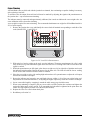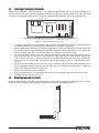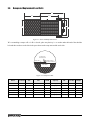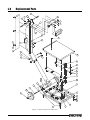
1
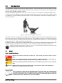
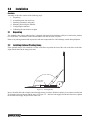
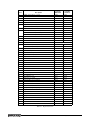
DeckHand
TM
Portable Floor Scale
Installation and
Service Manual
43978 Rev A
Contents
1.0
Introduction.................................................................................................................................. 1
1.1 Safety . . . . . . . . . . . . . . . . . . . . . . . . . . . . . . . . . . . . . . . . . . . . . . . . . . . . . . . . . . . . . . . . . . . . . . . . 1
1.2 Operating Requirements . . . . . . . . . . . . . . . . . . . . . . . . . . . . . . . . . . . . . . . . . . . . . . . . . . . . . . . . . 2
2.0
Installation ................................................................................................................................... 3
2.1
2.2
2.3
2.4
2.5
2.6
3.0
3
3
4
4
5
5
Service Information ..................................................................................................................... 6
3.1
3.2
3.3
3.4
3.5
3.6
4.0
Unpacking . . . . . . . . . . . . . . . . . . . . . . . . . . . . . . . . . . . . . . . . . . . . . . . . . . . . . . . . . . . . . . . . . . . .
Installing Optional Pivoting Ramp . . . . . . . . . . . . . . . . . . . . . . . . . . . . . . . . . . . . . . . . . . . . . . . . .
Mounting and Wiring the Mast and Indicator. . . . . . . . . . . . . . . . . . . . . . . . . . . . . . . . . . . . . . . . .
Corner Trimming . . . . . . . . . . . . . . . . . . . . . . . . . . . . . . . . . . . . . . . . . . . . . . . . . . . . . . . . . . . . . . .
Configuring the Indicator . . . . . . . . . . . . . . . . . . . . . . . . . . . . . . . . . . . . . . . . . . . . . . . . . . . . . . . .
Calibrating with Test Weights . . . . . . . . . . . . . . . . . . . . . . . . . . . . . . . . . . . . . . . . . . . . . . . . . . . . .
Troubleshooting Guide . . . . . . . . . . . . . . . . . . . . . . . . . . . . . . . . . . . . . . . . . . . . . . . . . . . . . . . . . . 6
Periodic Maintenance . . . . . . . . . . . . . . . . . . . . . . . . . . . . . . . . . . . . . . . . . . . . . . . . . . . . . . . . . . . 6
Load Cell Replacement . . . . . . . . . . . . . . . . . . . . . . . . . . . . . . . . . . . . . . . . . . . . . . . . . . . . . . . . . . 7
Installing Protective Clamshells . . . . . . . . . . . . . . . . . . . . . . . . . . . . . . . . . . . . . . . . . . . . . . . . . . 10
Mounting Indicator Brackets . . . . . . . . . . . . . . . . . . . . . . . . . . . . . . . . . . . . . . . . . . . . . . . . . . . . 10
Ramps and Replacement Load Cells . . . . . . . . . . . . . . . . . . . . . . . . . . . . . . . . . . . . . . . . . . . . . . 11
Replacement Parts .................................................................................................................... 12
DeckHand Limited Warranty .................................................................................................................. 14
L CO N F E
R
CE
t
t NA
TI
NA
EN
O
HT
S
EI
UR
ES
ON W
G
S AND ME
A
CC# 98-004
Class III
nmax = 2500
Copyright © 2013 Rice Lake Weighing Systems. All rights reserved. Printed in the United States of America
Specifications subject to changes without notice. Rice Lake Weighing Systems is an ISO Registered Company.
January 2013 - Revision A
ii
DeckHand Installation Manual
1.0
Introduction
The DeckHand™ Portable Floor Scales are fully electronic, NTEP-certified floor scales allowing one-person
portability on large rubber wheels. Available in painted steel or stainless steel construction, these rugged scales
come in 500 lb, 1000 lb, and 2000 lb capacity.
The heavy diamond-tread platform is 30-1/2 in x 24-1/4 in (0.77 m x 0.62 m) with an overall base height of only
4 1/2 in (0.11 m). The addition of an optional low-angle ramp allows one person to easily roll on a barrel or wheel
on a hand truck. The free-floating ramp pivots back over the deck and rests on the mast for compact storage or
balanced portability.
Figure 1-1. Optional Pivoting Ramp and Indicator
An efficient off-center arrangement of two high-capacity, single-point load cells yields Legal for Trade accuracy.
Electronic components are double-protected from rough use. A RoughDeck™ stainless steel NEMA 4X junction
box is further protected by mounting within the mast. The optional indicator mounts on a swivel bracket high
enough on the 59 in (1.50 m) mast to clear the tallest loads.
In addition to ramps, available options include stainless steel load cell guards (clamshell) and indicator brackets for
any Rice Lake IQ series indicator. Other indicators can be readily mast-mounted with slight modifications.
Authorized distributors and their employees can view or download this manual from the Rice Lake
Weighing Systems distributor site at www.rlws.com.
1.1
Safety
Safety Symbol Definitions:
DANGER Indicates an imminently hazardous situation that, if not avoided, will result in death or serious
injury.
WARNING Indicates a potentially hazardous situation that, if not avoided could result in serious injury or
death, and includes hazards that are exposed when guards are removed.
CAUTION Indicates a potentially hazardous situation that, if not avoided may result in minor or moderate
injury.
Important Indicates information about procedures that, if not observed, could result in damage to
equipment or corruption to and loss of data.
General Safety
Do not operate or work on this equipment unless you have read and understand the
instructions and warnings in this Manual. Failure to follow the instructions or heed the
warnings could result in injury or death. Contact any Rice Lake Weighing System dealer for
replacement manuals. Proper care is your responsibility.
Introduction
1
WARNING
Failure to heed may result in serious injury of death.
DO NOT allow minors (children) or inexperienced persons to operate this unit.
DO NOT operate without all shields and guards in place.
DO NOT jump up and down on the scale.
DO NOT use for purposes other then weight taking.
DO NOT place fingers into slots or possible pinch points.
DO NOT use any load bearing component that is worn beyond 5% of the original dimension.
DO NOT use this product if any of the components are cracked.
DO NOT exceed the rated load limit of the unit.
DO NOT make alterations or modifications to the unit.
DO NOT remove or obscure warning labels.
Before opening the unit, ensure the power cord is disconnected from the outlet.
Keep hands, feet and loose clothing away from moving parts.
1.2
Operating Requirements
Electrical Grounding
Rolling or wheeling loads onto the scale can build up large static charges that may damage the attached indicator
unless it is properly grounded to prevent ESD. This is especially true in dry environments where charges drain off
slowly, or if wheeling on materials which already contain a static charge, like rolls of paper or plastic film material
that have been recently spooled.
To prevent ESD damage, the indicator requires a three-prong 120 VAC outlet plug with continuous earth
Important ground. Do not attempt to use the scale with two-prong 120 VAC power without a ground.
Load Cell Excitation
Rated Excitation: 10 VDC
Maximum Excitation: 15 VDC
mV/V Signal Output: 2 mV/V
Grade Level Requirements
The bubble level built into the platform should indicate a level condition in use. On uneven floors, place temporary
shims under feet not contacting the floor.
Safe Static Overloading Capacity
Maximum: 150% of scale capacity
2
DeckHand Installation Manual
2.0
Installation
Overview
Assembly of the scale consists of the following steps:
1. Unpacking
2. Assembling mast onto scale base
3. Installing optional pivoting ramp
4. Mounting and wiring the indicator
5. Configuring the indicator
6. Calibrating the unit with test weights
2.1
Unpacking
The standard scale, with no added options, is shipped with load cells and indicator cable pre-wired into the junction
box on the mast. The indicator can be mounted and wired after the mast is in place.
Remove all packing material and inspect base and mast components for visible damage caused during shipment.
2.2
Installing Optional Pivoting Ramp
If the optional ramp is to be installed, set it flat on the floor in position in front of the scale so the holes in the base
align with the holes in the ramp pivot arms.
Shoulder Bolts,
Pivot Washers
Figure 2-1. Pivoting Ramp
Insert a shoulder bolt with a single washer through an arm pivot hole. Slide three plastic pivot washers onto the bolt
for clearance between the arm and the base. See Figure 3-5. After the bolt engages the threads in the base, tighten
the shoulder bolt snugly. Repeat for the other side.
Installation
3
2.3
Mounting and Wiring the Mast and Indicator
Assembling Mast to Base
Remove back plate from mast. Carefully insert mast into window in base. Align holes and secure with fasteners
(refer to Figure 4-1). Wrap excess cable around hooks in mast. Re-assemble back plate to mast.
Attaching Indicator Bracket to Mast
The DeckHand is supplied with a swivel bracket for a variety of RLWS indicators. If using a different bracket, bolt
it onto the mounting plate on the mast with the bolts, washers, and nuts provided.
Set the two large plastic washers provided near the thumbscrew bolts used to hold the indicator in the bracket. Put
the bolts and washers within close reach of the bracket—you’ll need them for the next step.
Mounting the Indicator
Spread the bracket arms enough to slide the indicator between the bracket arms. Line up the bracket holes with the
threaded enclosure holes. Slide a plastic pivot washer between each arm and the indicator enclosure at the holes.
Mounting Plate
Load Cell Cable
AC Power
Swivel Bracket
Threaded Insert
Indicator Enclosure
Plastic Pivot Washer
Thumbscrew Bolt
Figure 2-2. Top View of Indicator and Bracket
Insert the thumbscrew bolts through the bracket arms, through the washers, and into the threaded holes of the
indicator enclosure. Tighten bolts snugly so the indicator remains at the desired viewing angle.
Wiring Load Cell Cable to Indicator
The load cell cable from the J-box is pre-wired to the indicator terminal inside the j-box. Attach the loose end of
this cable to the indicator’s load cell input terminal according to the corresponding pin functions on the j-box
indicator terminal. When completed, tighten the cord grip around the cable where it passes through the indicator
case.
2.4
Corner Trimming
The DeckHand scales are factory-trimmed so each load cell shares an equal part of the weight load.
Further corner-trimming is unnecessary unless a load cell is replaced. See Section 3.0 for complete information on
corner-trimming after load cell replacement.
Load Cell Cable
Color Code
J-Box Terminal
Load Cell Cable Color
(load cells to j-box)
Green
Black
Red
White
Bare
+ Excitation
– Excitation
+ Signal
– Signal
Shield
Green/Blue
Black/Brown
Red
White
Yellow
Table 2-1. Load Cell Cable Wiring Code
4
DeckHand Installation Manual
2.5
Configuring the Indicator
Refer to the indicator manual for information on configuring the indicator for your application.
If using the DeckHand for a Legal for Trade application, do not configure the indicator for more divisions than the
NTEP Class III maximums below:
500 lb capacity
2500 divisions
1000/2000 lb capacity
2000 divisions
The following sample configuration parameters will yield those maximum divisions:
Scale Capacity
500 lb
1000 lb
2000 lb
Grads
25,000
20,000
20,000
Decimal Point
0.00
0.00
0.0
Display Divisions
2
5
1
Units
lbs
lbs
lbs
Table 2-2. Sample Configuration
2.6
Calibrating with Test Weights
Refer to the indicator operating manual to determine correct calibration procedure.
Before beginning calibration, put the scale in the same temperature environment where it will be used. Power up
the indicator so it can warm up for at least 20 minutes before starting calibration.
The scale should be “exercised” before calibration to be certain that everything is seated. Load the scale to near
capacity two or three times.
The following test weights are recommended for the most accurate calibration of the various models:
Scale Capacity
Test Weights (75%)
500 lb
375 lb
1000 lb
750 lb
2000 lb
1500 lb
Table 2-3. Sample Configuration
With scale base level and no load on the scale, place the indicator in calibration mode and do a zero calibration
according to the indicator manual.
Place test weights on the platform equal to the value shown in Table 3 (75% of the scale’s capacity). Do a span
calibration according to the indicator manual.
Remove the test weights and check the zero reading. Repeat the calibration process if necessary.
The calibrated DeckHand scale is now ready for operation.
Installation
5
3.0
3.1
Service Information
Troubleshooting Guide
Symptom
Possible Problem
Solution
System does not operate— Power disconnected
no display
Indicator fuse blown
Display stays at zero
Erratic weights
Consistently high or low
weights
Check and reconnect.
Check for cause. Replace.
Interface cable cut or disconnected
Repair.
Signal leads incorrectly connected at indicator
Install according to indicator installation
manual.
Indicator faulty
Service indicator.
Load cell connections faulty
Check cable connections in junction box and
at indicator.
Load cell overload screws turned fully in
Loosen overload screws to 0.020” gap.
Vibration near scale
Remove source of vibration or increase digital
filtering.
Platform not level
Level scale by shimming if necessary.
Load cell or cable water damage
Replace.
Debris under load cells or platform
Clean.
Indicator faulty
Use simulator to test indicator for stability.
Service indicator.
Indicator not properly adjusted to zero
Zero the indicator according to operating
manual.
Platform binding
Obtain adequate clearance for free platform
movement.
Indicator not calibrated
Calibrate according to indicator manual and
Section 2.6.
Load cells cables pinched between platform and
base
Reroute cables to provide clearance.
Load cells faulty
Test and replace load cells if necessary.
Table 3-1. Troubleshooting
3.2
Periodic Maintenance
Two important spaces—between the platform side and frame, and beneath the platform—should be periodically
cleaned to prevent debris build up.
The platform can be removed for periodic cleaning by unscrewing the lock nuts from the four welded studs on the
underside of the platform. The platform can then be lifted off the load cell channels for cleaning.
When cleaning beneath the platform, be careful not to move the load cell cables to a new position where they can
be pinched by the platform in operation.
Do not attempt to spray wash scales with non-hermetically sealed load cells.
Important common cause of failure in non-hermetically sealed load cells.
Water damage is a
Use care with hot water wash downs for hermetically-sealed load cells. The hot water may not damage the load
cells, but the elevated temperatures can cause incorrect readings until the unit cools to room temperature.
When replacing the platform, tighten the four locknuts on the welded studs only until the flat washers beneath them
contact the channel surface. Do not tighten the nuts further and compress the cushion pads between platform and
channels. The platform must be free-floating on resilient pads for continued accuracy.
6
DeckHand Installation Manual
3.3
Load Cell Replacement
Disassembly
1. Remove the four locknuts and washers that secure the platform to load cell channels. Lift off the platform.
Remove the column back plate to gain access to the j-box.
2. Determine which load cell is defective. Use a hardened hex-drive bit and large ratchet wrench to remove
the four hex-drive countersunk machine screws holding the channel to the defective load cell underneath.
Lift off the channel and the spacer on top of the load cell. Note how the load cell cable is routed on its cable
hold downs.
3. Cut the plastic tie at each hold-down to free the cable. Remove the load cell wires from the load cell
terminal in the J-box. Loosen the cord grip and pull the cable out of the J-box. Unwind the excess cable
from the cable-storage studs and pull it out of the mast cavity.
4. Turn the scale on its side to remove the lower load cell screws. With the hex-drive bit and ratchet wrench,
remove the four cap screws and lock washers that hold the cell to the mounting plate. Lift off the cell and
spacer plate beneath.
Reassembly
Tilt and block the scale base enough that you have comfortable access to the load cell screws from underneath the
base. Position the new load cell with the cable to the inside and the label readable from the outside. Be sure the load
cell body is not contacting the overload stop screw. Back the screw off if necessary (it was secured with Loctite at
the factory and will turn hard).
1. Set the spacer block and load cell into position. Insert the four load cell screws from the bottom finger-tight
only; final adjustments in load cell position are necessary before the screws are torqued down.
2. Run the new load cell cable to the J-box using exactly the path dictated by the cable existing ties. The
existing cable hold downs keep the cables under the middle of each load cell channel, where they are
protected from accidental crimping between the flexing channels and the frame. When new cable ties are
attached, feed the cable through the cutout in the frame and into the mast cavity. Do not shorten the load
cell cable; it is temperature-compensated for the supplied cable length. Wind the excess cable around the
cable-storage studs, leaving enough free to wire into the junction box.
3. With the load cell still loose enough for final adjustment, set the top spacer block and load cell channel on
the cell and insert the self-centering countersunk load cell screws. Tighten these screws alternately with a
hex-drive bit and ratchet wrench to a final torque of 20 ft-lb for mild steel models and 12 ft-lb for stainless
steel models.
4. Adjust the load cell/channel assembly so it is parallel with the other channel. Measure across the holes in
the front and rear of the channels. Adjust the new cell so that distance is equal, then tighten the load cell
cap screws from underneath to a final torque of 20 ft-lb for mild steel models and 12 ft-lb for stainless steel
models. Check again to be certain the cable will not be pinched by the flexing channel in operation.
5. Finally, put a drop of Loctite on the overload stop screw and set it for a 0.020" gap with the load cell.
Wiring Load Cells into J-Box
Feed the load cell cable into the j-box cord grip closest to its terminal. When facing the scale, the left load cell is
wired to terminal 4 of the j-box, and the right load cell is wired to terminal 1.
Note that the wire traces for cells 2 and 3 (JU-2, JU-3 ) have been cut, making those unused channels inactive.
Connect wires according to Table 2-1 on page 4. Pull excess cable out of the J-box and tighten the cable cord grip
snugly. The rubber seal will protrude slightly from the cord grip when tightened enough to be waterproof.
Service Information
7
+EX
–EX
+SI
–SI
SHD
SHD
–SI
+SI
–EX
+EX
100 K
JU2
JU3
CELL 3
CELL 2
100 K
–EX
+SI
100 K
–SE
–SI
+EX
+SI
SHD
+SE
–SI
SHD
JU4
SHD
–SI
JU1
CELL 4
+EX
–EX
+SI
–EX
+EX
CELL 1
100 K
23126
Rev. A
INDICATOR
(Cells 2 & 3 disabled)
Figure 3-1 DeckHand Junction Box Cutaway
Replacing Deck Platform
Put the scale flat on the floor and set the platform on the channels so the welded studs drop into the channel holes.
Tilt and block the scale up again and install a flat washer and locknut on each stud. Turn the lock nut onto each stud
until the washer just contacts the channel underside. Do not tighten the lock nuts so the cushioning pads are
compressed. The platform must be free floating for accuracy; the lock nuts merely serve as lift off protection.
8
DeckHand Installation Manual
Corner Trimming
100 K
JU4
JU1
CELL 4
+EX
–EX
+SI
–SI
SHD
–SI
SHD
+SI
–EX
+EX
CELL 1
100 K
All DeckHand scales are delivered with the junction box trimmed, but re-trimming to equalize loading is necessary
after replacing a load cell.
To trim the scale, the output from each load cell must be matched by adjusting the signals with potentiometers at
the junction box—a process known as trimming.
The indicator must be connected and approximately calibrated, but it need not indicate the exact weight value. An
exact calibration will be done after trimming.
A test weight is required for corner trimming. The recommended minimum test weight for all DeckHand models is
25% of scale capacity.
1. Remove the junction box cover and identify the correct load cell terminal corresponding to each side of the
scale (labeled CELL 1, and CELL 4).
Figure 6: Cell 1 and Cell 4 Potentiometers
2. With scale level and no weight on the scale, zero the indicator. Then turn potentiometers for cells 1 and 4
fully clockwise to get the maximum signal from each load cell. A clicking sound can be heard when full
signal is reached.
3. With both potentiometers at full signal, place the test weight over left or right side of platform and record
the indicated weight reading. Repeat the process for the other side. The load cell with the lowest reading
will be used as the reference cell and will not be trimmed.
4. Place the test weight over the side reading high and turn that cell’s potentiometer to adjust the cell output
down to the reference cell output.
5. Rezero the indicator and repeat the test until both sides are within ±0.1% of the test weight being used.
Adjustments are somewhat interactive, so adjusting the higher output may affect the reference cell output.
6. Secure extra cable length by wrapping it around the cable storage pegs inside the mast.
7. When corner trimming is complete, pull any excess cable out of the junction box enclosure and tighten the
strain relief hubs snugly with a wrench. To be watertight, the hubs must be tightened to the point where the
rubber sleeving begins to protrude out of the hub (SST models).
8. Replace the J-box cover and column back plate.
9. Recalibrate per Section 2.6.
Service Information
9
3.4
Installing Protective Clamshells
Stainless steel clamshells—load cell protectors—are mounted around the load cells to provide an extra degree of
spray protection. The lower protector is slightly smaller than the upper one which overlaps on all sides. The load
cell cable exits through the bottom surface of the lower clamshell then through a hole in the mounting plate.
Top Spacer Block
Overload Screw, 0.020” gap
Bottom Spacer Block
Figure 3-2 Clamshell Load Cell Protectors
1. To attach clamshells, remove all channels, load cell screws and load cells. Place lower clamshell directly
on mounting plate with overload stop screw centered in the clamshell’s largest hole.
2. Add mounting spacer and align all four holes. Position load cell on spacer and insert load cell screws and
lock washers from beneath mounting plate through clamshell and spacer and into load cell. Tighten the
four screws finger tight only so the cell can still be moved slightly for final positioning.
3. For final positioning, measure to be sure load cells are parallel to each other and to the frame. It may be
easier to mount one load cell first so it is parallel to the frame, then measure equal distances between the
ends of the two load cells to get them parallel with each other. When correctly positioned, retighten the
load cell screws to original torque specifications (20 ft-lb for mild steel screws, 12 ft-lb for stainless steel
screws).
4. Position top spacer blocks on load cells, then set upper clamshells on spacer blocks and align holes. Place
load cell channels so all four holes line up, then turn in the self-centering countersunk screws. Tighten to
same torque settings as lower load cell screws.
5. Replace scale deck onto load cell channels.
6. Reset overload stop screws by turning them in until they just contact the load cell, then back off 0.020".
7. Calibrate scale according to Section 2.6.
3.5
Mounting Indicator Brackets
A universal mount plate is welded to the DeckHand mast. The plate is predrilled to match the bracket of most
indicators and are supplied with the appropriate painted or stainless steel mounting hardware.
Figure 3-3 Indicator Bracket
10
DeckHand Installation Manual
3.6
Ramps and Replacement Load Cells
41
27
30.5
24.25
25
31
Figure 3-4 Scale and Ramp Dimensions
W h e n attaching a ramp to a D e c k H a n d scale, place one plastic p i v o t washer under the head of the shoulder
bolt and three washers on the bolt in the space between the ramp arm and the scale deck.
Socket head
shoulder bolt
Ramp arm
Plastic washer
3 plastic washers
Scale deck
Figure 3-5 Ramp Pivot Bolt
DeckHand
Model
Scale PN
Overall
Size
Platform Deck
Size
Load
Cell PN
Load Cell
Capacity
Ramp
PN
Ramp
Deck Size
Ramp
Weight
DH-500
41293
31"W 41"L
24.25"W 30.5"L
41024
250 kg b)l(550
43376
25"W 27"L
44 lb
DH-1000
41294
31"W 41"L
24.25"W 30.5"L
41026
500 kg b)l(1100
43376
25"W 27"L
44 lb
DH-2000
41295
31"W 41"L
24.25"W 30.5"L
41027
635 kg b)l(1397
43378
25"W 27"L
57 lb
DH-500SS
41296
31"W 41"L
24.25"W 30.5"L
41024
250 kg b)l(550
43377
25"W 27"L
44 lb
DH-1000SS
41297
31"W 41"L
24.25"W 30.5"L
41026
500 kg b)l(1100
43377
25"W 27"L
44 lb
DH-2000SS
41298
31"W 41"L
24.25"W 30.5"L
41027
635 kg b)l(1397
43379
25"W 27"L
57 lb
Service Information
11
4.0
Replacement Parts
29
31
30
29
2
32
4
1
5
3
39
43
40
52
35
34
51
36
37
6
38
41
7
46
8
9
10
11
23
12
22
28
13
50
27
26
15
25
16
17
18
19
53
Figure 4-1 Replacement Parts Illustration
12
DeckHand Installation Manual
14
Ref.
1
2
3
4
5
6
7
8
9
10
11
12
13
14
15
16
17
18
19
22
23
25
26
27
28
29
30
31
32
35
36
37
38
39
40
41
43
46
50
51
52
53
Description
Cable, 6-Conductor, 3 1/2 ft
Mount, Indicator, 310A
Grommet, Rubber 1/2 x 1/4
Flat Washer, 1/4
Cap Screw, 1/4-20NC x 3/4
Upper Platter (DH-500, DH-1000)
Upper Platter (DH-2000)
Cap Screw, 5/16-18 NC x 1
Load Cell Channels (DH-500)
Load Cell Channels (DH-1000)
Load Cell Channels (DH-2000)
Flat Washer, 5/16
Lock Nut, 5/16-18 NC, Hex
Shim, Load Cell
Load Cell
Base Platform (DH-500, DH-1000)
Base Platform (DH-2000)
Cap Screws, 5/16-18NC x 1
Overload Stop Set Screw, 5/16 x 18NC x 1/2
Base Shim, Ramp End
Scale Base Bumper, 3/4
Cap Screw, 1/4-20NC x 3/4
Lock Washer, 5/16
Cable Tie Mount
Cable Tie, 3"
Lock Nut, 5/8-11NC
Wheel, 10 Dia. x 5/8 Bore
Axle, 5/8-11 x 6
Jam Nut, 5/8-11NC
Handle Grip, 3/4 I.D.
Mast, 57-13/16 x 15
Lock Washer, 1/4
Hex Nut, 1/4-20NC
Junction Box, Four Channel
Flat Washer, 3/8
Lock Washer, 3/8
Hex Nut, 3/8-16NC
Dampener Strip, Ramp Stop
Cap Screw, 10-32NF x 3/4
Cap Screw, 3/8-16NC x 6
Bubble Level
Bumper Cushion, Self-Adhesive
Nylon Washer, 5/8
Column Back Plate
Cap Screw, 10-32NF x 3/8
Base Shim, All Corners
Part No.
Mild Steel
Part N0.
Stainless
15494
44187
41011
41206
15398
15377
15145
15149
14965
41251
40986
41181
42654
42655
14996
41250
41002
41197
41002
42665
42664
42653
21939
44237
14646
35170
41003
41198
See table on page 7
40983
41178
42616
42617
26667
26670
14989
21933
41004
41199
41267
41267
14964
41251
15153
15154
15658
15658
15631
15631
40181
41249
41268
41268
41005
41200
14676
14680
41266
41266
40987
41182
15147
15148
14641
14642
43612
23127
21938
15161
15159
15160
14656
14655
41108
41108
14908
41253
41254
41257
15410
15410
44149
44149
15176
15176
46259
46260
14932
46337
47726
47727
Table 4-1. Repair Parts List
Replacement Parts
13
DeckHand Limited Warranty
Rice Lake Weighing Systems (RLWS) warrants that all RLWS equipment and systems properly installed by a
Distributor or Original Equipment Manufacturer (OEM) will operate per written specifications as confirmed by the
Distributor/OEM and accepted by RLWS. All systems and components are warranted against defects in materials
and workmanship for one year.
RLWS warrants that the equipment sold hereunder will conform to the current written specifications authorized by
RLWS. RLWS warrants the equipment against faulty workmanship and defective materials. If any equipment fails
to conform to these warranties, RLWS will, at its option, repair or replace such goods returned within the warranty
period subject to the following conditions:
• Upon discovery by Buyer of such nonconformity, RLWS will be given prompt written notice with a
detailed explanation of the alleged deficiencies.
• Individual electronic components returned to RLWS for warranty purposes must be packaged to prevent
electrostatic discharge (ESD) damage in shipment. Packaging requirements are listed in a publication,
Protecting Your Components From Static Damage in Shipment, available from RLWS Equipment Return
Department.
• Examination of such equipment by RLWS confirms that the nonconformity actually exists, and was not
caused by accident, misuse, neglect, alteration, improper installation, improper repair or improper testing;
RLWS shall be the sole judge of all alleged non-conformities.
• Such equipment has not been modified, altered, or changed by any person other than RLWS or its duly
authorized repair agents.
• RLWS will have a reasonable time to repair or replace the defective equipment. Buyer is responsible for
shipping charges both ways.
• In no event will RLWS be responsible for travel time or on-location repairs, including assembly or
disassembly of equipment, nor will RLWS be liable for the cost of any repairs made by others.
THESE WARRANTIES EXCLUDE ALL OTHER WARRANTIES, EXPRESSED OR IMPLIED,
INCLUDING WITHOUT LIMITATION WARRANTIES OF MERCHANTABILITY OR FITNESS FOR A
PARTICULAR PURPOSE. NEITHER RLWS NOR DISTRIBUTOR WILL, IN ANY EVENT, BE LIABLE
FOR INCIDENTAL OR CONSEQUENTIAL DAMAGES.
RLWS AND BUYER AGREE THAT RLWS’S SOLE AND EXCLUSIVE LIABILITY HEREUNDER IS
LIMITED TO REPAIR OR REPLACEMENT OF SUCH GOODS. IN ACCEPTING THIS WARRANTY,
THE BUYER WAIVES ANY AND ALL OTHER CLAIMS TO WARRANTY.
SHOULD THE SELLER BE OTHER THAN RLWS, THE BUYER AGREES TO LOOK ONLY TO THE
SELLER FOR WARRANTY CLAIMS.
NO TERMS, CONDITIONS, UNDERSTANDING, OR AGREEMENTS PURPORTING TO MODIFY
THE TERMS OF THIS WARRANTY SHALL HAVE ANY LEGAL EFFECT UNLESS MADE IN
WRITING AND SIGNED BY A CORPORATE OFFICER OF RLWS AND THE BUYER.
© 2013 Rice Lake W eighing System s,Inc.Rice Lake,W IU SA. AllRights Reserved.
RICE LAKE WEIGHING SYSTEMS • 230 WEST COLEMAN STREET • RICE LAKE, WISCONSIN 54868 • USA
14
DeckHand Installation Manual
2013 Rice Lake Weighing Systems
PN 119071 01/13