1
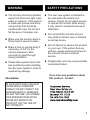
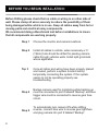
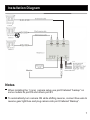
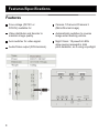
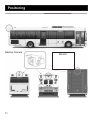
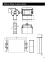
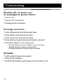
Product Manual
InstalIation Instructions
Rear View Camera System
© 2009-2010 Rear View Safety Inc.
Table of Contents
Important Notice
4
Warning
5
Safety Precautions
5
Before You Begin Installation
6
Installation Diagram
7
Features/Specifications
8
Specifications
9
Positioning
10
Dimensions - Camera
11
Dimensions - Monitor
12
Product Info - Camera
13
Product Info - Monitor
14
Monitor Control and Operation
15
Troubleshooting
16
Warranty
17
3
IMPORTANT NOTICE
Please read thiswith manual before proceeding
installation.
Congratulations on your
purchase of a Rear View
Backup Camera System.
Your Backup Camera System is
designed to provide you with
many years of trouble-free.
Installation Location
In some jurisdictions, it is
unlawful for a person to
drive a motor vehicle
equipped with a
TV viewer or screen located
forward of the back of the
driver's seat or in any
location that is visible,
directly or indirectly, to the
driver while operating the
vehicle.
In most jurisdictions, it is
unlawful for a person to
drive a motor vehicle
equipped with a
TV, TV monitor or screen
located forward of the back
of the driver's seat or in any
4
With this manual you will
be able to properly install
and operate the unit.
The Backup Camera
System is intended to be
installed as a supplement
aid to your standard rearview mirror that exist in
your vehicle. The Backup
Camera System is not
intended for use as a
substitute for rear-view
mirror or for any other
motor vehicle
WARNING
n The monitor should be situated
away from direct sun light, heat,
water or moisture. (This product
is made with precise electronic
components that should be
handled with care. Do not let it
fail because of improper use.
SAFETY PRECAUTIONS
n The rear view system is intented to
be used when the vehicle is in
reverse. Please do not watch movies
or operate the monitor while driving.
It may result in accident because of
distraction.
n Do not install the monitor where it
n Make sure the monitor stand is
firmly fixed to secure location.
n Make a hole on vehicle body if
necessary, of 3/4” for the
camera extension cable
connector to pass through
during installation.
n Please take special care to the
wire positioning while installing
the rear view system in order to
avoid wiring damage.
Information
may obstruct drivers view or obstruct
an air bag device.
n Do not attempt to service this product
on your own. If the system has any
problem, please disconnect power to
the unit and contact customer
service.
n Dropping the unit may cause possible
mechanical failure.
If you have any questions about
this product , contact :
IN NO EVENT SHALL SELLER
OR MANUFACTURER BE
LIABLE FOR ANY DIRECT OR
CONSEQUENTIAL DAMAGES
OF ANY NATURE, OR LOSSES
OR EXPENSES RESULTING
FROM ANY DEFECTIVE
PRODUCT OR THE USE OF
ANY PRODUCT.
5
BEFORE YOU BEGIN INTALLATION:
Before Drilling please check that no cable or wiring is on other side of
wall. Please clamp all wires securely to reduce the possibility of them
being damaged while vehicle is in use. Keep all cables away from hot or
moving parts and electrical noisy components.
We recommend doing a Benchmark test before installations to insure
that all components are working properly.
Step 1
Choose the monitor and camera locations.
Step 2
Install all cables in vehicle, when necessary a ¾”
(19mm) hole should be drilled for passing camera
cable through vehicles walls. Install split grommets
where applicable.
Tep 3
Once all cable/ and wiring have been properly placed
and routed, perform a system function test by
temporarily connecting the system. If the system
seems to not be operating properly see
troubleshooting.
Step 4
Step 5
6
Backup camera used for monitoring while backing up
must be connected to port # labeled “Backup” and blue
trigger wire must be connected to reverse gear fuse
circuit.
To automatically turn camera ON while shifting
reverse, connect blue wire to reverse gear light/fuse
and plug camera into port # labeled “Backup”.
Installation Diagram
3
Fuse
Monitor
Notes
When installing the 1 (one) camera setup use port # labeled “backup” on
some models its port #2 and others port #3
To automatically turn camera ON while shifting reverse, connect blue wire to
reverse gear light/fuse and plug camera into port # labeled “Backup”.
7
Installation
Notes
To automatically have camera and monitor turn ON when vehicles activates,
simply twist BLUE positive trigger 12V+ to Red Power line 12V+ and wire to
ignition power which can be an accessory switch/fuse line.
When using a 2 camera setup, use ports #'s 2 and 3
For Safety reasons, on some 1 camera setup systems, when port #
“Backup” is activated it overrides port #1. On these systems customer can
have system ““on” all the time (see note above) or just in “reverse” not both
options.
Audio only activates when REVERSE “BLUE” trigger is put to power
Audio only works on two ports on multiplexer.
1. port labeled “BACKUP”
2. Port Labeled “DVD”.
On some models when “BLUE” trigger is activated it overrides port#1 and
port #1 cannot be seen until the “blue” trigger is deactivated.
There is a built in voltage range for our systems which can handle 12-24
volts real consumption is 10 to 30 Volts.
When installing a TWO camera setup, use ports #2 and #3 and use positive
triggers Blue and White.
When installing all three cameras, use all three ports and connect all
positive triggers to appropriate connections.
When installing a one (1) camera setup, use port #3. Place blue trigger
wire to reverse power line. Place red wire to positive and black wire to
ground. Do not use yellow and white power cables.
8
Features/Specifications
Features
Free voltage (DC12V or
DC24V) available for
Camera 1/Camera 2/Camera 3
(Mirror/Normal image)
Video distributor and booster to
maintain image quality.
Automatically switches to reverse
image when backing vehicle.
Auto switcher for video signal.
Night Vision: 18 powerful LEDs
allow seeing rearward in total
pitch darkness, as if using a spotlight.
Audio/Video output (RCA terminal).
9
Specifications
4
5
Port #3
Camera - Port #2
Camera Port #1
Camera 2
Backup
10
Positoning
Backup Camera
11
Monitor
Dimensions - Camera (mm)
12
Dimensions - Monitor (mm)
(some models)
13
Product Info
14
Product Info
7”(L) x 5” (H) x 1”(D)
Rear View Safety Inc. reserve the right to change or modify product specifications
or measurements without notice.
15
Monitor Control and Operation
1
1
2
3
4
5
2
3
4 5 6
7
8
Earphone jack.
Audio/Video devices input jack.
Lower volume. When in Menu mode: selection key.
V1/V2 - Channel selection. Switches from Camera 1, 2 and 3.
Menu key:
Brightness
Contrast
Color
Volume
Dislay mode: 16:0 or 4:3
Tcon: rotate image 360°
AV select (same as V1/V2 - channel selection).
Language selection:
English, Chinese, Japanese, German, French, Spanish,
Portuguese and Russian.
■
■
■
■
■
■
■
■
6 Higher volume. When in Menu mode: selection key.
7 Power - On/Off
8 Power indicator LED.
16
Troubleshooting
Monitor will not power up /
no backlight on power button
• Check fuse
• Check 12v+ to monitor.
• Check ground connection.
No image on screen
• Verify camera is on correct camera input.
• Verify cable is connected to monitor.
• Verify camera is connected to cable.
• Connect known good camera and cable to monitor.
• Verify Blue trigger is receiving power.
• If image appears connect cable to existing camera
• If image remains replace original cable.
• If image disappears replace original camera.
No audio
• Verify selected camera has audio.
• Verify volume setting.
• Confirm that the Blue audio trigger is connected to 12v+
17
Warranty
One Year Warranty
Rear View Safety Inc. warrants this product against material defects for
a period of one year from date of purchase. We reserve the right to repair
or replace any such defective unit at our sole discretion. Rear View
Safety Inc. is not responsible for a defect in the system as a result of
misuse, improper installation, damage or mis-handling of the electronic
components. Rear View Safety Inc. is not responsible for consequential
damages of any kind.
This warranty is void if: defects in materials or workmanship or damages result from repairs or
alterations which have been made or attempted by others or the unauthorized use of
nonconforming parts; the damage is due to normal ware and tear, this damage is due to
abuse, improper maintenance, neglect or accident: or the damage is do to use of the Rear
View Safety Inc. system after partial failure or use with improper accessories.
Warranty Performance
DURING THE ABOVE WARRANTY PERIOD, SHOULD YOUR REAR VIEW SAFETY
PRODUCT EXHIBIT A DEFECT IN MATERIAL OR WORKMANSHIP, SUCH DEFECT
WILL BE REPAIRED WHEN THE COMPLETE REAR VIEW SAFETY INC. PRODUCT
IS RETURNED, POSTAGE PREPAID AND INSURED, TO REAR VIEW SAFETY INC.
OTHER THAN THE POSTAGE AND INSURANCE REQUIREMENT, NO CHARGE
WILL BE MADE FOR REPAIRS COVERED BY THIS WARRANTY.
Warranty Disclaimers
NO WARRANTY, ORAL OR WRITTEN, EXPRESSED OR IMPLIED, OTHER THE
ABOVE WARRANTY IS MADE WITH REGARD TO THIS REAR VIEW SAFETY INC.
REAR VIEW SAFETY INC. DISCLAIMS ANY IMPLIED WARRANTY OR
MERCHANTABILITY OR FITNESS FOR A PARTICULAR USE OR PURPOSE AND
ALL OTHER WARRANTIES. IN NO EVENT SHALL REAR VIEW SAFETY INC.
LIABLE FOR ANY INCIDENTAL, SPECIAL, CONSEQUENTIAL, OR PUNITIVE
DAMAGES OR FOR ANY COSTS, ATTORNEY FEES, EXPENSES, LOSSES OR
DELAYS ALLEGED TO BE AS A CONSEQUENCE OF ANY DAMAGE TO, FAILURE
OF, OR DEFECT IN ANY PRODUCT INCLUDING, BUT NOT LIMITED TO, ANY
CLAIMS FOR LOSS OF PROFITS.
18
Rear View Safety, Inc.
1680 Atlantic Ave # 301
Brooklyn, N.Y. 11213
(800) 764-1028
www.rearviewsafety.com