1
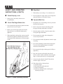
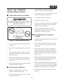
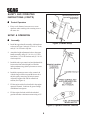
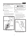
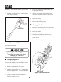
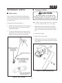
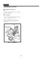
OPERATORS MANUAL MODEL SE-3.5BS THIS MANUAL CONTAINS THE OPERATING INSTRUCTIONS AND SAFETY INFORMATION FOR YOUR SCAG EDGER. READING THIS MANUAL WILL PROVIDE YOU WITH MAINTENANCE AND ADJUSTMENT PROCEDURES TO KEEP YOUR EDGER PERFORMING TO MAXIMUM EFFICIENCY. THE SPECIFIC MODELS THAT THIS BOOK COVERS ARE CONTAINED ON THE INSIDE COVER. BEFORE OPERATING YOUR MACHINE, PLEASE READ ALL THE INFORMATION ENCLOSED. PART NUMBER 03070 WARNING FAILURE TO FOLLOW SAFE OPERATING PRACTICES MAY RESULT IN SERIOUS INJURY. * Keep all safety shields in place. * Before performing any maintenance or service, stop the machine and remove the spark plug wire. * If a mechanism becomes clogged, stop the engine before cleaning. * Keep hands, feet and clothing away from power-driven parts. * Read this manual completely. * Keep others away from the edger while operating. REMEMBER - YOUR EDGER IS ONLY AS SAFE AS THE OPERATOR! Hazard control and accident prevention are dependent upon the awareness, concern, prudence, and proper training of the personnel involved in the operation, transport, maintenance, and storage of the equipment. This manual covers the operating instructions and illustrated parts list for: SE-3.5BS with a serial number of 4800001- 4809999 Always use the entire serial number listed on the serial number tag when referring to this product. ® TABLE OF CONTENTS SUBJECT PAGE Introduction .............................................................................................................. 1 Safety and Operating Instructions ........................................................................... 1-3 Setup & Operation ................................................................................................... 4-5 Maintenance ............................................................................................................ 6-8 Troubleshooting Guide ............................................................................................. 9 Illustrated Parts List ................................................................................................. 10-11 Limited Warranty Statement................................................................... Inside Back Cover MEMBER c WE SUPPORT OPE Equipment & Engine Training Council TECHNICIAN CERTIFICATION I INTRODUCTION SAFETY AND OPERATING INSTRUCTIONS This manual has been prepared to provide the information you need to correctly assemble, operate, and maintain this edger. Read it carefully and keep it for future reference. CAUTION: To avoid personal injury, it is imperative that all safety instructions be observed. The replacement of any part on this product by other than the manufacturer's authorized replacement part may adversely affect the performance, durability or safety of this product. n A replacement manual is available from your authorized Scag Service Dealer or by contacting: Scag Power Equipment, Service Department at P.O. Box 152, Mayville, WI 53050. Please indicate the complete model and serial number of your Scag product when ordering a replacement manual. USE OF OTHER THAN ORIGINAL SCAG REPLACEMENT PARTS WILL VOID THE WARRANTY. If additional information or service is needed that is not outlined in this manual, please contact your Scag Power Equipment dealer. Scag dealers are trained in the latest service methods and carry a full line of Scag replacement parts. Your edger is only as safe as YOU, the operator. As with any power equipment, carelessness or error can result in serious bodily injury. Improper maintenance can also result in injury. To reduce the potential for injury, follow these instructions on safe operation. When ordering parts, always provide the complete model and serial number of your edger. n All information provided in this manual is based upon information available at the time of printing. Scag Power Equipment reserves the right to make changes at any time without notice or obligation. n How To Use This Edger 1. Be thoroughly familiar with the controls and the proper use of the machine. 2. Know how to stop the edger and disengage the controls quickly. Direction Reference The "Right" and "Left", "Front" and "Rear" of the machine are referenced from the normal operating position. n Read This Operator's Manual 3. Use the edger only on flower beds and lawns. 4. Always stay behind the handles. Stones and other items thrown by the blade can cause serious injury (See Figure 1, page 2). Servicing The Engine The detailed servicing of the engine is not covered in this manual. For service of the engine it is important to contact your Scag Dealer or an authorized servicing agent of the engine manufacturer. Any unauthorized work performed on the engine will void the warranty. 5. Do not modify or alter any component of the edger. n Dress Properly 1. Wear safety glasses or goggles. 2. Do not wear loose clothing or jewelry; they can be caught in moving parts. Always wear long pants that cover your legs. 1 SAFETY AND OPERATING INSTRUCTIONS (CONT'D) n n 2. Do not operate the edger when you are fatigued or under the influence of alcohol or drugs. 1. Watch what you are doing. Use common sense. Dress Properly, cont. 3. Sturdy gloves and safety footwear are recommended. n Stay Alert n Operate With Care Check The Edger Before Use 1. Keep hands, feet, and clothing well away from the blade and moving parts. 1. Never operate the edger unless guards and other protective devices are in place. 2. Don't overreach or stand on unstable ground. Keep good footing and balance at all times. 2. Before you use the edger, make sure all nuts, bolts, and screws are installed and properly tightened. 3. Start the engine carefully. Stop the engine when leaving the edger unattended. 3. Where applicable, check pulley setscrews and all fasteners for tightness and lubricate periodically as described in the maintenance section on pages 6 and 7. 4. Do not operate the edger with a damaged or excessively worn blade. 5. Never attempt to make adjustments when the edger is running. 6. Never direct discharge of material toward people. Use care in directing discharge to avoid glass enclosures or automobiles. 7. Never operate the edger without good visibility or light of day. 8. Stay alert for uneven sidewalks, holes in the terrain, or other similar conditions when using the edger. Always push slowly over rough ground. 9. Always keep the throttle in the STOP position when the edger is not in use. 10. If the edger strikes a foreign object: (1) stop the engine. (2) disconnect the spark plug lead. (3) inspect for damage. (4) repair any damage before restarting and operating the edger. ath P e ctil e j Pro Figure 1, Proper Operating Position 2 SAFETY AND OPERATING INSTRUCTIONS (CONT'D) n 3. After operating the edger, stop the engine and allow the engine to cool before refueling. 4. To reduce the risk of fire, replace the gasoline cap securely after adding fuel to the tank. Keep Hands And Feet From Blade 5. Use an approved gasoline container. 6. Do not store gasoline in a house. The rotating blade is sharp and can severely cut body parts. The blade coasts after the edger is turned off (See Figure 2). 7. If gasoline is spilled on the ground, move the edger and the gasoline container from the area and do not create a source of ignition. 8. If gasoline is spilled on clothing, remove the stained clothes and replace them with clean, dry clothes before operating the edger. n Follow Maintenance Instructions Carefully 1. Disconnect the spark plug lead before servicing any part of the edger. Figure 2, Protect Hands And Feet 2. To reduce the risk of fire, do not allow excessive grass, leaves, lubricants or gasoline to accumulate on the edger. 1. Keep both hands on the handles when the blade is rotating. 2. Keep your feet and hands away from the cutting area. 3. Do not attempt to make repairs other than those identified in this manual. Repairs not detailed in this manual should be performed by an authorized Scag dealer. See that only identical replacement parts are used. P R O P E R Y L 3. Do not attempt to remove cut material or hold S E C R E V I material to be cut when the engine is running orE N N G E I the blade is moving. W T H I W T H I OL I 4. Make sure the spark plug wire is disconnected A N D when clearing jammed material from the blade or FUEL. cutter head. 4. When cleaning, repairing, or inspecting the edger, make certain the blade and all moving parts have stopped. Disconnect the spark plug wire. 5. When lifting or transporting the edger, firmly grasp a solid part of the frame. Do not lift the edger by the clutch or height adjustment assemblies. Blade is sharp! Be careful of the blade when lifting. 5. Disengage the blade and stop the engine when the edger is transported or not in use. n Handle Gasoline With Care 6. Do not run the edger indoors; exhaust fumes are dangerous. 1. Gasoline is highly flammable. Never add gasoline to a running or hot engine. 2. Refuel outdoors in an open area only. Never fill the gasoline tank indoors. 3 SAFETY AND OPERATING INSTRUCTIONS (CONT'D) n Operator presence shown separated for illustration purpose only. Protect Operators 1. Keep a safe distance between two or more operators when working with a cutting crew at the same site. SETUP & OPERATION n Assembly Figure 3, Handle Setup 1. Install the upper handle assembly with hardware as shown in Figure 3 using (4) 5/16-18 x 1" bolts, and (4) 5/16-18 elastic stop nuts. 2. Attach the height adjustment index to the upper handle assembly using (2) 5/16-18 x 1-1/2" hex head bolts, (2) 5/16 flat washers and (2) 5/16-18 elastic stop nuts. 3. Install the tube-type control rod on right hand side between the front wheel height lever and the index quadrant using (4) hair pin cotters to secure the control rod. 4. Install the operator presence safety control rod with the long rod at the top and the short rod at the idler pulley arm using (4) hair pin cotters. Adjust the length of the rod for normal belt tension (See Figure 4). 5. Fill the engine with oil as described in the engine operator's manual. Lubricate all grease fittings with lithium-based grease. 6. Fill the engine fuel tank with fresh unleaded gasoline that has a minimum octane rating of 87. Figure 4, Operator Presence Controls 4 SETUP & OPPERATION (CONT'D) n Starting The Engine n Operating Instructions CAUTION: Figure 5 is a general view of the edger. Be sure no one is standing near the blade. Keep body parts away from the blade. Before starting, clear operating area of foreign objects, sticks, stones, etc. Note: The right or left side of the edger refers to the view from the normal operating position, behind the handles. n Before Operation Refer to the engine operator's manual for starting instructions. 1. Check the engine oil level as detailed in the engine operator's manual. n 2. Before starting the engine, be sure the blade has a free arc of travel and the blade is fully raised. Damage to the blade can result if the blade is not in the highest position (See Figures 5 and 6). 1. Move the edger to the working area. Operation 2. Pull the operator presence safety levers up to engage the blade (See Figure 7) and carefully raise the front wheel until the blade is at the desired cutting depth. When the height adjustment lever is all the way forward, the blade is 1/2 inch from the ground. The blade is lowered approximately 1/4 inch for each notch in the height adjustment index. Figure 5, Edger Controls Figure 6, Edger Blade Controls 5 SETUP & OPPERATION (CONT'D) 4. Remove the oil drain plug and drain the oil into an appropriate container. 3. Push the edger forward slowly, adjust your pace to the engine's capacity. 5. After the oil is drained, replace the drain plug and refill the crankcase to the level specified in the engine owner's manual. 6. Replace the oil cap. 7. Dispose of the used oil properly. n Changing The Belt 1. Remove the flat bar belt guide at the front of the spindle boom assembly (See Figure 8). 2. Remove the old belt. 3. Install the new belt. Do not attempt to pry or force the belt into the pulley grooves as this may damage the belt. 4. Replace the front belt guide. Figure 7, Engaging The Blade MAINTENANCE CAUTION: To prevent injury from rotating parts turn the engine stop switch to OFF and disconnect the spark plug wire from the engine before attempting any maintenance. n Changing Engine Oil Oil should be changed after the first 20 hours of use and then after every 50 hours of use. 1. Start the engine and allow it to warm up. 2. Turn the engine switch to OFF. Make sure the blade has stopped turning. Disconnect the spark plug wire. Figure 8, Belt Replacement 3. Carefully clean all debris from around the oil filler cap. Remove the cap. 6 n MAINTENANCE (CONT'D) n Changing the Blade CAUTION: Belt Tension The blade is sharp! Wear gloves when changing the blade. Do not operate the edger with a damaged or excessively worn blade. Always adjust the belt tension after changing the belt. New belts may stretch. Excess tension on the belt will make holding the clutch difficult and cause the belts to wear. Note: Blades must be balanced before installation to prevent vibration and wear to the edger. To adjust belt tension (See Figure 9): 1. Remove the cotter pin from the lower control rod and disconnect the lower control rod from the idler pulley assembly. 1. While holding the hex bolt head by the spindle pulley, remove the nut and washer and carefully remove the blade from the assembly (See Figure 10). 2. To increase the belt tension, loosen the hex nut and turn the lower control rod to shorten the rod. Retighten the nut after the rod is reinstalled. 2. Install the new blade. 3. Replace the nut and washer. 4. Tighten the nut securely. Keep the spindle shaft from rotating with a wrench on the hex nut located on the pulley. Figure 10, Blade Replacement Figure 9, Belt Tension 7 MAINTENANCE (CONT'D) n Rubber Debris Deflector Replace the rubber deflector when worn or damaged to prevent operator injury. n Lubrication Grease the edger periodically at the points shown on Figure 11. Use lithium-based grease. Note: The spindle bearings are sealed and permanently lubricated. They should require no maintenance. Figure 11, Lubrication 8 TROUBLESHOOTING GUIDE Problem Engine fails to start Cause Fuel level is low. Spark plug lead wire disconnected. Throttle or choke not in starting position. Spark plug defective. Carburetor improperly adjusted. Old/stale gasoline. Engine kill switch in off position. Hard starting or loss of power Carburetor improperly adjusted. Spark plug wire loose. Dirty air cleaner. Operation erratic Dirt in gasoline tank. Dirty air cleaner. Water in fuel supply. Vent in gas cap and/or carburetor plugged. Carburetor improperly adjusted. Engine skips at high speed Spark plug fouled, faulty, or gap too wide. Carburetor improperly adjusted. Dirty air cleaner. Engine idles poorly Carburetor idle speed too slow. Carburetor improperly adjusted. Spark plug gap too close. Carburetor idle mixture improperly set. 9 8 7 12 24 A 25 12 62 51 61 53 46 31 33 18 37 20 20(REF.) 37 3 27 14 63 4 59 49 3 10 49 3 13 36 4 46 43 41 44 46 36 47 57 50 13(REF.) 17 43 39 4 18 52 4 60 3 49 58 59 45 45 55 43 22 ED GE R 10 15 19 29 48 32 CO MM ER CI AL G 24 6 34 IN A 26 N 5 28 R 2 15 A 53 W 1 U K S D EE E E O P EY B NG N A E E IN O R P F T O E O EA RO R R P C T E U E L E U N R E CT S N A A IO E IN T R E . G W OF N. U IT B R N H Y O A O S T T U T A T T A T E N G ND ING D U E E A R B D R S L . D T A R S O DE E IN R M A D P E A O LA DU Y P C C T E E E H A . R R T O D IS OW R O K 'S N O O M O F BJ A T IN E N L J C U E U TS A AV R . L E Y . LAWN EDGER SE-3.5BS 30 30 36 R 23 9 54 3 54 4 21 11 10 38 16 9 18 39 49 36 44 40 35 48 42 49 54 50(REF.) 54 52 39 54 56 390S0184 LAWN EDGER SE-3.5BS Ref. Part No. No. 1 2 3 4 5 6 7 8 9 10 11 12 13 481886 04001-12 04030-03 04021-10 04063-05 48451 45291 44048 04041-07 04001-16 04001-43 48114-04 46321 14 15 16 17 18 19 20 21 22 23 24 25 26 27 28 29 30 31 04050-02 04001-21 48441 04030-04 04021-09 48144 45229 43147 04041-10 48050 45288 43138 42595 04020-04 04001-11 461178 48448 04001-44 Description Engine, 3.5 HP. Briggs & Stratton Bolt, Hex Head 5/16-18 x 1.75" Lockwasher, 5/16" Spring Locknut, 5/16-18 Hex Elastic Stop Key, 3/16 x 3/16 x 1.50" Pulley, 2.50 Dia. - .75 Bore Engine Engine Adapter Bracket Belt Guide, Engine Flatwasher, 3/8" (.391 x .938 x .105) Bolt, Hex Head 5/16-24 x 1.25" Bolt, Hex Head 5/16-24 x .75" Grease Fitting Idler Pulley Arm Assy.(Includes Bushings & Grease Fittings) Retaining Ring, 3/4" External "E" Bolt, Hex Head 3/8-16 x 1.75" Pulley, Idler Lockwasher, 3/8" Spring Nut, 3/8-16 Hex Elastic Stop Grip, Height Adjustment Lever Height Adjustment Lever Index Pin Flatwasher, 3/8" (.375 x 2.0 x .060) Spring Control Rod, Wheel Height Adjustment Sleeve Plate, Height Adjustment Index Nut, Hex 3/8-16 Bolt, 5/16-18 x 1-1/2" Hex Head Handle Assembly, (Includes Grips & Decal) Grip, Handle Bolt, Hex Head 1/4-20 x 1/2" 32 33 34 35 36 37 38 39 40 41 42 43 44 45 46 47 48 49 50 51 52 53 54 55 56 57 58 59 60 61 62 63 04012-04 04030-02 48454 481043 04062-02 48100-05 44039 04001-09 45269 45226 42591 43141 48446 43211 04021-07 45228 48453 04020-03 46359 04001-84 04004-11 48452 04040-04 48444 04020-07 48626 43139 48442 42584 48440 45231 04001-47 Set Screw, 5/16-18 x 3/8" Lockwasher, 1/4" Spring Decal, SCAG Decal, Warning Hair Pin, .080 x 1.19 Bearing, Oilite Control Rod, Upper Bolt, Hex Head 5/16-18 x 1" Control Rod, Lower Frame Weldment, Engine Deck Debris Guard Spacer, Rear Wheel Wheel, Rear Washer, Step 2.00" Dia. Nut, 1/2-13 Hex Elastic Stop Spindle Boom Weldment Rubber Deflector Nut, Hex 5/16-18 Blade Guard, With Decal Bolt, 1/2-13 x 4-1/2" Hex Head Stud, 5/16-18 x 3" Grade 5 Belt Flatwasher, 5/16" (.344 x .688 x .065) Blade Nut, Hex 1/2-13 Pulley Spindle Shaft, Spindle Bearing, Spindle Belt Guide Wheel, Front Bracket, Front Wheel Bolt, Hex Head 3/8-16 x 5" * Common hardware which should be purchased locally. All bolts Grade 5 plated, all other fasteners zinc plated. WARNING USE EYE PROTECTION. ROTATING BLADE MAY THROW OBJECTS. KEEP AREA CLEAR OF BYSTANDERS TO REDUCE RISK OF INJURY. DO NOT OPERATE WITHOUT GUARDS IN PLACE. DO NOT LEAVE ENGINE RUNNING UNATTENDED. READ OPERATOR'S MANUAL BEFORE USE. 481043 481043 R COMMERCIAL EDGER 48454 11 LIMITED WARRANTY- COMMERCIAL A CCESSOR Y ACCESSOR CCESSORY Any part of the Scag commercial accessory manufactured by Scag and found, in the reasonable judgment of Scag, to be defective in material or workmanship, will be repaired or replaced by an Authorized Scag Service Dealer without charge for parts and labor. The Scag accessory, including any defective part, must be returned to an Authorized Scag Service Dealer within the warranty period. The expense of delivering the accessory to the dealer for warranty work and the expense of returning it back to the owner after repair or replacement will be paid for by the owner. Scag’s responsibility in respect to claims is limited to making the required repairs or replacements, and no claim of breach of warranty shall be cause for cancellation or rescission of the contract of sale of any Scag machine. Proof of purchase will be required by the dealer to substantiate any warranty claim. All warranty work must be performed by an Authorized Scag Service Dealer. This warranty is limited to 90 days from the date of original retail purchase for any Scag accessory that is used for commercial purposes, or any other income-producing purpose including rental use. This warranty does not cover any accessory that has been subject to misuse, neglect, negligence, or accident, or that has been operated in any way contrary to the operating instructions as specified in the Operator's Manual. The warranty does not apply to any damage to the accessory that is the result of improper maintenance, or to any accessory or parts that have not been assembled or installed as specified in the Operator's Manual. The warranty does not cover any accessory that has been altered or modified. In addition, the warranty does not extend to repairs made necessary by normal wear, or by the use of parts or accessories which, in the reasonable judgment of Scag, are either incompatible with the Scag mower or adversely affect its operation, performance or durability. This warranty does not cover engines and electric starters, which are warranted separately by their manufacturer. Scag Power Equipment reserves the right to change or improve the design of any accessory without assuming any obligation to modify any accessory previously manufactured. All other implied warranties are limited in duration to the 90 day warranty period. Accordingly, any such implied warranties including merchantability, fitness for a particular purpose, or otherwise, are disclaimed in their entirety after the expiration of the appropriate ninety day warranty period. Scag’s obligation under this warranty is strictly and exclusively limited to the repair or replacement of defective parts and Scag does not assume or authorize anyone to assume for them any other obligation. Some states do not allow limitations on how long an implied warranty lasts, so the above limitation may not apply to you. Scag assumes no responsibility for incidental, consequential or other damages including, but not limited to, expense for gasoline, oil, expense of delivering the machine to an Authorized Scag Service Dealer and expense of returning it back to the owner, mechanic’s travel time, telephone or telegram charges, rental of a like product during the time warranty repairs are being performed, travel, loss or damage to personal property, loss of revenue, loss of use of the mower, loss of time, or inconvenience. Some states do not allow the exclusion or limitation of incidental or consequential damages, so the above limitation or exclusion may not apply to you. This warranty gives you specific legal rights, and you may also have other rights which vary from state to state. © 1998 SCAG POWER EQUIPMENT DIVISION OF METALCRAFT OF MAYVILLE, INC PART NO. 03070 PRINTED 12/98 PRINTED IN USA