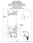
1
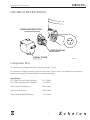
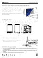
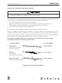
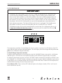
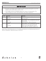
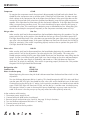
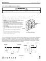
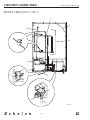
Service and Parts Manual
Supplement
For Model
CLRCO2075
U-Line Corporation
8900 North 55th Street
Milwaukee, WI 53223
U-Line Corporation
PO Box 245040
Milwaukee, WI 53224-9540
www.U-LineService.com
Phone (414) 354-0300 • FAX (414) 354-7905
Service & Parts Tech Lines Phone (800) 779-2547 • FAX (414) 354-5696
R
INTRODUCTION
Design ■ Features ■ Performance
INTRODUCTION
Three generations of pride and quality manufacturing and design improvements are built into all U-Line
products. The result: U-Line leads the market with innovative technology and superior craftsmanship.
This manual contains specific instructions for servicing the U-Line Échelon CLRCO2075.
Potential Problems With HFC-134A
This Service Manual has been written to cover product manufactured with HFC-134a. HFC-134A compressors will be received with a synthetic based ester oil charge. The hygroscopic (water attraction) property of
ester oil is many times greater than that of the mineral oils previously used with CFC-12. High system
moisture causes the formation of acids and alcohol which can damage the compressor. Systems should not
be left open for more than fifteen (15) minutes at any time as humidity from the air will enter system. To
assure system dehydration, the system should be pulled down to 100 microns and vacuum pump oil (mineral oil) must not be allowed to enter the system.
Cleanliness of the system will be extremely important. The presence of residues (chlorinated or greasy
residues, mineral oil, or impurities) can lead to capillary tube restrictions, oil return problems and compressor damage. Flux must not be used on brazed joints.
2
INTRODUCTION
Design ■ Features ■ Performance
SERIAL NUMBER FORMAT
The serial number is divided into four segments. A typical serial number is 035497-03-0004.
The first two digits of the first segment, 03, represents the year the unit was made.
The next four digits of the first segment, 5497, represents the shop order number. Order number 5497 is
assigned for the Model CLRCO Black_00 units.
The second two digit segment, 03, represents the month the unit was made.
The third four digit segment, XXXX, is a factory internal control number used at U-Line Corporation.
035497-01-XXXX
Year
Shop Month
Order
Number
3
Factory Internal
Control Number
INTRODUCTION
Design ■ Features ■ Performance
NOTES
4
INTRODUCTION
Design ■ Features ■ Performance
TABLE OF CONTENTS
Introduction . . . . . . . . . . . . . . . . . . . . . . . . . . . . . . . . . . . . . . . . . . . . . . . . . . . . . . . . . . . . . . . . . . . . 2
Serial Number Format . . . . . . . . . . . . . . . . . . . . . . . . . . . . . . . . . . . . . . . . . . . . . . . . . . . . . . . . . . 3
General Information . . . . . . . .
Limited Warranty . . . . . . . .
Warranty Claims Procedure
Safety Precautions . . . . . . .
.
.
.
.
.
.
.
.
.
.
.
.
.
.
.
.
.
.
.
.
.
.
.
.
.
.
.
.
.
.
.
.
.
.
.
.
.
.
.
.
.
.
.
.
.
.
.
.
.
.
.
.
.
.
.
.
.
.
.
.
.
.
.
.
.
.
.
.
..................................
..................................
..................................
..................................
.
.
.
.
.
.
.
.
.
.
.
.
6
6
7
8
Servicing . . . . . . . . . . . . . . . . . . . . . . . . . . . . . . . . . . . . . . . . . . . . . . . . . . . . . . . . . . . . . . . . . . . . . . 9
Electrical Specifications . . . . . . . . . . . . . . . . . . . . . . . . . . . . . . . . . . . . . . . . . . . . . . . . . . . . . . . . . 9
Leveling and Installation Requirements . . . . . . . . . . . . . . . . . . . . . . . . . . . . . . . . . . . . . . . . . . . . . 10
Gravity Drain Installation . . . . . . . . . . . . . . . . . . . . . . . . . . . . . . . . . . . . . . . . . . . . . . . . . . . . . . . 11
Connecting a Drain Pump . . . . . . . . . . . . . . . . . . . . . . . . . . . . . . . . . . . . . . . . . . . . . . . . . . . . . . 12
Self-Cleaning Cycle Instructions . . . . . . . . . . . . . . . . . . . . . . . . . . . . . . . . . . . . . . . . . . . . . . . . . . .13
Interior Storage Bin Cleaning . . . . . . . . . . . . . . . . . . . . . . . . . . . . . . . . . . . . . . . . . . . . . . . . . . . . .14
Principles of Operation . . . . . . . . . . . . . . . . . . . . . . . . . . . . . . . . . . . . . . . . . . . . . . . . . . . . . . . . .14
Sequence of Operation . . . . . . . . . . . . . . . . . . . . . . . . . . . . . . . . . . . . . . . . . . . . . . . . . . . . . . . . .16
Thermistors . . . . . . . . . . . . . . . . . . . . . . . . . . . . . . . . . . . . . . . . . . . . . . . . . . . . . . . . . . . . . . . . . .24
Controller . . . . . . . . . . . . . . . . . . . . . . . . . . . . . . . . . . . . . . . . . . . . . . . . . . . . . . . . . . . . . . . . . . .25
CLRCO2075 Control Board Diagnostics . . . . . . . . . . . . . . . . . . . . . . . . . . . . . . . . . . . . . . . . . . . . 27
Refrigeration System Diagnosis Guide . . . . . . . . . . . . . . . . . . . . . . . . . . . . . . . . . . . . . . . . . . . . . .29
Ice Thickness Adjustment . . . . . . . . . . . . . . . . . . . . . . . . . . . . . . . . . . . . . . . . . . . . . . . . . . . . . . .30
Troubleshooting . . . . . . . . . . . . . . . . . . . . . . . . . . . . . . . . . . . . . . . . . . . . . . . . . . . . . . . . . . . . . . 33
CLRCO2075 Wiring Diagram . . . . . . . . . . . . . . . . . . . . . . . . . . . . . . . . . . . . . . . . . . . . . . . . . . . . 35
Parts Listing . . . . . . . . . . . . . . . . . . . . . . . . . . . . . . . . . . . . . . . . . . . . . . . . . . . . . . . . . . . . . . . . . 36
CLRCO2075 Model Parts . . . . . . . . . . . . . . . . . . . . . . . . . . . . . . . . . . . . . . . . . . . . . . . . . . . . . . . . . 38
5
GENERAL INFORMATION
Design ■ Features ■ Performance
LIMITED WARRANTY
U-Line Corporation warrants each U-Line product to be free from defects in materials and workmanship
for a period of one year from the date of purchase; and warrants the sealed system (consisting of the compressor, the condenser, the evaporator, the hot gas bypass valve, the dryer and the connecting tubing) in
each U-Line product to be free from defects in materials and workmanship for a period of five years from
the date of purchase. During the initial one-year warranty period for all U-Line products U-Line shall: (1)
at U-Line’s option, repair any product or replace any part of a product that breaches this warranty; and (2)
for all Marine, RV and Domestic U-Line products sold and serviced in the United States (including Alaska
and Hawaii) and Canada, U-Line shall cover the labor costs incurred in connection with the replacement
of any defective part. During years two through five of the warranty period for the sealed system, U-Line
shall: (1) repair or replace any part of the sealed system that breaches this warranty; and (2) for all
Marine, RV and Domestic U-Line products sold and serviced in the United States (including Alaska and
Hawaii) and Canada, U-Line shall cover the labor costs incurred in connection with the replacement of
any defective part of the sealed system. All other charges, including transportation charges for replacements under this warranty and labor costs not specifically covered by this warranty, shall be borne by you.
This warranty is extended only to the original purchaser of the U-Line product. The Registration Card
included with the product should be promptly completed by you and mailed back to U-Line, or you can
register on-line at www.U-LineService.com.
The following are excluded from this limited warranty: installation charges; damages caused by disasters or
acts of God, such as fire, floods, wind and lightening; damages incurred or resulting from shipping,
improper installation, unauthorized modification, or misuse/abuse of the product; customer education
calls; food loss/spoilage; door and water level adjustments (except during the first 90 days from the date of
purchase); defrosting the product; adjusting the controls; door reversal; or cleaning the condenser.
If a product defect is discovered during the applicable warranty period, you must promptly notify either the
dealer from whom you purchased the product or U-Line at P.O. Box 23220, Milwaukee, Wisconsin 53223
or at 414-354-0300. In no event shall such notification be received later than 30 days after the expiration
of the applicable warranty period. U-Line may require that defective parts be returned, at your expense, to
U-Line’s factory in Milwaukee, Wisconsin, for inspection. Any action by you for breach of warranty must
be commenced within one year after the expiration of the applicable warranty period.
This limited warranty is in lieu of any other warranty, express or implied, including, but not limited to
any implied warranty of merchantability or fitness for a particular purpose; provided however, that to
the extent required by law, implied warranties are included but do not extend beyond the duration of the
express warranty first set forth above. U-Line’s sole liability and your exclusive remedy under this warranty is set forth in the initial paragraph above. U-Line shall have no liability whatsoever for any incidental, consequential or special damages arising from the sale, use or installation of the product or from any
other cause whatsoever, whether based on warranty (express or implied) or otherwise based on contract,
tort or any other theory of liability.
Some states do not allow limitations on how long an implied warranty lasts or the exclusion or limitation
of incidental or consequential damages, so the above limitations may not apply to you. This warranty gives
you specific legal rights, and you may also have other rights which vary from state to state.
6
GENERAL INFORMATION
Design ■ Features ■ Performance
WARRANTY CLAIMS PROCEDURE
When submitting claims for warranty payment, please follow these guidelines.
You can use any form you would normally use to bill your customer (your own computer generated form,
Narda, USA, etc.).
The model and serial number MUST be on the claims. Claims will not be paid without a model and serial
number.
If you work on more than one unit per service call please submit a separate claim for each unit.
We track all defects through warranty claims, so please be specific on what the repair was. If it is a system
leak, please specify where the leak was.
Please be sure the claim is legible. If the claim form cannot be read, it will be returned, unpaid.
U-Line will not cover part or labor claims for the replacement of a complete ice maker assembly. All ice
maker parts are available as replacement parts and are stocked in our inventory. Remember: we do not
pay customer education calls. Door and water level adjustments are 90 day warranties only.
If you are changing out a unit please supply the model and serial number of both units (the unit being
replaced and the new unit) and the R.A. number.
Occasionally the customer does not return their warranty cards. In this case we use the date the unit was
shipped to our distributor for a beginning warranty date. This may cause the claim to be rejected for a
proof of purchase. If a copy of the Proof of Purchase/Install is not available at the site, the technician
should record the following information on the Labor Invoice:
• The name of the selling Dealer
• The date of purchase/installation
• The Order or Invoice number (if available)
• The type of document they saw i.e. Store Receipt, Closing Papers, Sign-Off of Building Permit,
Final Walk Through, etc.
If we have this information on the Labor Invoice, and we have the other information that is needed (correct Serial Number, type of repair, time spent on repairs, etc.), we will be able to process the invoice for
you in a timely manner.
At U-Line, parts and labor claims are paid separately. Included in labor are freon and recovery charges, all
other parts are handled by the parts department. We require that some parts be returned to us, so we may
return them to our vendor. It will be noted on your packing list if we require you to return the part. If a
part is to be returned please include a copy of the packing list and a copy of your claim. If the part was
purchased at one of our part distributors, you must handle the part warranty with that company. For labor
payment please send a readable copy of your claim to U-Line Corporation, P.O. Box 245040, Milwaukee
WI, 53224-9540, for warranty payment.
7
GENERAL INFORMATION
Design ■ Features ■ Performance
SAFETY PRECAUTIONS
Do not attempt to service or repair the unit until you have read the entire procedure. Safety items throughout this manual are labeled with Warning or Caution.
! WARNING !
Warning means that failure to follow this safety statement may result in extensive product
damage, serious personal injury, or death.
!
Caution means that failure to follow this safety statement may result in minor or moderate
personal injury, property or equipment damage.
! WARNING !
DANGER: Risk of child entrapment. Before you throw away an old refrigerator or freezer:
Take off the doors, leave shelves in place so that children may not easily climb inside.
! WARNING !
•
•
Never attempt to repair or perform maintenance on the unit until the electricity has been
disconnected.
Altering, cutting of power cord, removal of power cord, removal of power plug, or direct
wiring can cause serious injury, fire and/or loss of property and/or life and will void the
warranty.
!
•
•
•
•
Do not lift unit by door handle.
Never use an ice pick or other sharp instrument to help speed up defrosting. These
instruments can puncture the inner lining or damage the cooling unit.
Failure to clean the condenser every three months can cause the unit to malfunction. This
could void the warranty.
Never install the unit behind closed doors. Be sure front grille is free of obstruction.
Obstructing free air flow can cause the unit to malfunction, and may void the warranty.
8
SERVICING
Design ■ Features ■ Performance
ELECTRICAL SPECIFICATIONS
OVERLOAD PROTECTOR
R
S
C
STARTING RELAY
RELAY COVER
CLRCO036
Compressor Pins
To measure start winding resistance, measure across the C-S pins.
To measure run winding resistance, measure across the C-R pins. These pins should never measure any
resistance to ground. This would indicate a shorted compressor.
Specifications
FF7.5HBK Compressor Start Winding:
FF7.5HBK Compressor Run Winding:
11.2 OHMS
2.2 OHMS
Water Valve Coil Resistance:
280 OHMS
Bypass Coil Resistance:
380 OHMS
Pump Motor Winding Resistance:
71.5 OHMS
9
SERVICING
Design ■ Features ■ Performance
LEVELING AND INSTALLATION REQUIREMENTS
It is extremely important that the unit is level. If it is not
level, the ice mold will not fill evenly. This can cause a
reduction in ice rate, uneven sized cubes or water spilling
into the storage area which will cause the ice in the bin to
melt prematurely. See Figure A.
Remember the floor surrounding a drain has a tendency to
slope towards the drain.
Figure A
Leveling the Unit
UL307
1. Use a level to check the icemaker from front to back and from side to side. See Figure B. Use a level to
check the levelness of the icemaker from front to back and from side to side by placing a level on the
inside edge and along the door seal edge for built-in installation. See Figure B.
FRONT
SIDE
CLRCO029
CLRCO006
Figure B
2. If the icemaker is not level, adjust the feet on the
corners of the unit as necessary. See Figure C.
3. Check after each adjustment and repeat the previous
steps as necessary until the unit is level.
RAISE
•
•
DWR005
Figure C
Installation Requirements
•
LOWER
The unit may be built into a cabinet. There is no minimum clearance requirement for the top, left or
right sides of the unit.
The location must allow enough clearance for water, drain, and electrical connections in the rear of
the unit.
The location must not obstruct air flow to the front of the unit.
10
SERVICING
Design ■ Features ■ Performance
GRAVITY DRAIN INSTALLATION
!
Plumbing installation must observe all state and local codes.
These guidelines must be followed when installing drain lines to prevent water from flowing back into the
ice maker storage bin and potentially flowing onto the floor causing water damage:
•
•
•
•
Drain lines and fittings must have a 5/8" inside diameter.
Drain lines must have a 1" drop per 48" of run (1/4" per foot) and must not create traps.
The floor drain must be large enough to accommodate drainage from all drains.
Insulate the bin drain line to prevent condensation.
Be sure to follow these guidelines to prevent water backing up into the storage bin.
Below are examples of gravity drain line installations. If a trap is in the drain line, the drain line must be
vented to assure proper draining. Without the vent, water will backup until enough pressure builds up to
force the water past the trap. Water may backup into the ice bin before the amount of pressure needed is
achieved. Water in the storage bin will cause the ice in the bin to melt prematurely.
The customer’s complaint will be slow ice production. The ice that has been made is melting
prematurely because water is backing up in the ice bin.
FROM ICE MAKER
TO FLOOR DRAIN
1. Normal Drain.
Pitched from ice maker
at least 1/4" per foot.
Proper Drainage
2. With Trap.
Poor drainage.
Water backs up in drain line.
Poor Drainage
3. With Trap and Vent.
Vent assures proper drainage.
Proper Drainage
UL306
Examples of Gravity Drain Installations
11
SERVICING
Design ■ Features ■ Performance
CONNECTING A DRAIN PUMP
!
Plumbing installation must observe all state and local codes. All water and drain connections
MUST BE made by a licensed/qualified plumbing contractor. Failure to follow recommendations
and instructions may result in damage and/or harm.
If a gravity drain connection is not available, U-Line strongly recommends the use of the U-Line P60 drain
pump. If your CLRCO2075 is not equipped with a factory installed pump, a P60 drain pump is available
through your Dealer, or direct from U-Line. If a pump other than the U-Line P60 drain pump is to be used,
it must meet the following specifications:
•
•
•
•
•
•
•
It must be UL listed and have a UL listed, 120 VAC, 3-wire grounded power cord.
Overall maximum outside dimensions of 8-3/4" wide x 5-3/4" deep x 7-3/4" high.
Minimum flow rate of 15 gallons per hour at 10 feet of lift.
It must have a sealed sump which does not allow water leakage in the case of a power outage, restricted
drain or pump failure.
It must have a check valve in the discharge line to prevent waste water return to the pump.
It must have an overflow protection control which will shut off power to the ice maker in the event of
a pump failure.
Operating temperature range of 50°F to 110°F (10°C to 40°C).
If the CLRCO2075 is not equipped with a P60 drain pump or an equivalent drain pump, severe damage
and costly repair could result in the event of a power outage, restricted drain or pump failure.
12
SERVICING
Design ■ Features ■ Performance
SELF-CLEANING CYCLE INSTRUCTIONS
To maintain operational efficiency, clean unit every six months (depending on water conditions more or
less frequent cleaning may be necessary). If the ice maker requires more frequent cleaning, consult a qualified plumber to test the water quality and recommend appropriate treatment. Use only U-Line Ice Machine
Cleaner (part number 41978).
!
Use only U-Line Ice Machine Cleaner (part number 41978). It is a violation of Federal law
to use this solution in a manner inconsistent with its labeling. Use of any other cleaner can
ruin the finish of the evaporator and will void the warranty. Read and understand all labels
printed on the package before use. Ice machine cleaner is used to remove Lime scale and
other mineral deposits. Refer to the following steps for mineral deposit removal.
FRONT COVER
1. Remove perishables from the refrigerator.
2. Set the cycle selector switch (located in the RH side of the grille) to OFF.
Allow the ice to melt off of the evaporator.
3. Remove all ice from the storage bin.
4. Remove inside front cover by gently pulling away from sidewall.
See Figure A.
5. Remove the overflow tube by lifting it up while using a slight back and
forth motion to loosen it from the drain hole. See Figure B. The water in
the reservoir will flow down the drain.
6. Replace the overflow tube after all the water has been drained from the
reservoir.
7. Move the cycle selector switch to the CLN position.
8. When water begins to flow over the evaporator, approximately three
minutes, add one packet of U-Line Ice Machine Cleaner to the reservoir.
9. Reinstall inside front cover.
10. When the self cleaning process stops, approximately 45 minutes, it may
be desirable to clean the storage bin. See INTERIOR STORAGE BIN
CLEANING.
11. Move the cycle selector switch to the ON position to resume ice
production.
12. Make sure the drain system is working properly and the drain hose is not
pinched or kinked. Pour one gallon of cool, fresh water into the ice bin.
The water should drain freely. If your CLRCO2075 is equipped with a
drain pump, the pump should drain the ice bin.
UL208
Figure A
OVERFLOW
CLRCO012
Figure B
NOTE
Ice production after the first harvest may take longer after Self Cleaning Cycle since the
refrigeration portion will take precedence over producing ice to protect any perishables.
Once the refrigerator reaches a set temperature, ice making will resume to normal.
13
SERVICING
Design ■ Features ■ Performance
INTERIOR STORAGE BIN CLEANING
1. Disconnect power from the ice maker.
2. Remove any ice from the storage bin.
3. Wipe down the storage bin with a solution of non-abrasive mild soap or detergent and warm water.
Rinse with clean water. Sanitize the bin with a solution of one tablespoon of bleach and one gallon of
water. Rinse thoroughly with clean water.
4. Check that all drain connections are in place.
5. Reconnect power to the unit.
6. Make sure the drain system is working properly and the drain hose is not pinched or kinked. Pour one
gallon of cool, fresh water into the ice bin. The water should drain freely. If your CLRCO2075 is
equipped with a drain pump, the pump should drain the ice bin.
PRINCIPLES OF OPERATION
The U-Line Model CLRCO2075 combines the best of Échelon refrigeration and clear ice making capabilities into a single unit. A state-of-the-art microprocessor based controller simplifies operation and troubleshooting. There are four primary modes of operation:
1. Ice Making and Refrigeration
2. Ice Making and No Refrigeration
3. Refrigeration and No Ice Making
4. Ice Harvest (No Refrigeration Possible)
In
5.
6.
7.
8.
addition, there are four sub modes of operation:
All Satisfied
Water Fill - No Refrigeration Required
Cleaning (No Refrigeration Possible)
Water Fill with Refrigeration Required
Review the following notes for general information before reading the schematics.
These are some additional general notes and exceptions:
1. The controller has a four-minute compressor minimum off-cycle regardless of thermistor status, for
compressor protection and cycling.
2. When making ice, the controller reads liquid line temperature four minutes into the ice making cycle
to determine the length of that ice making cycle and subsequent harvest length.
3.
4.
5.
Once an ice making cycle is initiated, it will continue through to harvest regardless of the bin sensor.
There is a three-minute water fill cycle when the unit is turned on, or following a cleaning cycle. If
the refrigerator is warmer than set point (which it probably will be on initial installation) there will be
cooling on the refrigerator side as shown in Mode 8. If the refrigerator is below set point for any reason (recent operation, cold product, etc.), the refrigerator side will not run and the operation will be
as shown in Mode 6.
In order to maintain adequate refrigerator temperature, the unit will sometimes run in the refrigeration
only mode, as shown in Mode 3, even if the ice bin sensor is calling for ice. At the end of each ice
harvest, the controller checks the refrigerator sensor and if it is warmer than the higher of 42°F, or the
set point, it will go into refrigeration only mode. If it reaches 42°F and the set point is lower, it will
continue to refrigerate and start an ice making cycle. If it reaches a higher set point (say 45°F), it will
switch to ice making only mode. There is no fill cycle when ice making re-initiates in this case,
because the bin sensor has not been satisfied.
14
SERVICING
Design ■ Features ■ Performance
6.
When the initial three-minute fill cycle is complete, the unit will enter ice making and refrigeration
mode (1) if the bin is empty or below the sensor. However, after the first slab of cubes is harvested,
the controller will follow the logic defined in #5 above and realizing the refrigerator is too warm, will
continue in refrigeration only mode (3) until the requirement is satisfied. Thus, upon start-up, the user
will see one slab of ice dropped in about 30 minutes, and then there will be no more ice until the
refrigerator reaches 42°F or a higher set point (this may be 2 to 3 hours depending on ambient conditions).
7.
There will also be a water fill cycle after the ice bin has been “full” and then calls to make ice again.
This can occur when the refrigerator side is off as shown in Mode 6, or when it is on, which is shown
in Mode 8. If the refrigerator side is on, when the fill cycle initiates, it will remain on until the fill
cycle is completed, even if the refrigerator sensor is satisfied.
8.
The controller has a four degree differential designed into it for the refrigerator sensor, such that when
it is set to 38°F, the refrigerator will cool until the refrigerator sensor reads 36°F and will not re-initiate
refrigerator cooling until the sensor reaches 40°F. So someone monitoring actual temperature (by
pressing WARMER momentarily) may see the refrigerator off when the temperature is a degree
warmer than set point, or refrigerator on when it is a degree below set point. Refer to Controller.
9.
The controller is equipped with two error indicator LEDs on the display module:
• One LED dot flashes to indicate the P60 drain pump is, or has been, restricted. If the pump or line
clears itself, the unit will re-initiate operation, but the light will stay on until the unit is unplugged
or power to the unit is broken. In the event that the P60 pump shuts down the clear ice maker
operation the refrigerator side will continue to operate normally.
• The other LED dot indicates that one or more of the thermistors has failed or been out of limits.
If the bin sensor or liquid line sensor fails, the refrigerator will continue to operate, but ice making
will be shut down. If the refrigerator sensor fails, the refrigerator will be shut down, but the
ice maker will continue to operate. A sensor would normally fail by opening up (no continuity) or
shorting (no resistance). Refer to CONTROLLER for more information.
10. There is no high limit cut-out on this unit, however, if the liquid line sensor were to go out of range
(approximately 185°F), the thermistor error indicator light will flash, and the ice maker side of the unit
will shut down. The refrigerator will continue to run. When the temperature of the liquid falls back in
range, the unit will re-initiate operation, even though the error indicator light stays on. The unit will
not normally experience this condition up to 110°F, but conditions such as door openings, heavy
loading, restricted airflow, dirty condenser, or direct sun light may contribute to reaching this mode.
11. In both modes, unit on, but no need for ice or refrigeration, and Mode 7, clean cycle. The evaporator
bypass valve coil is energized, even though the REF VALVE relay is off. This is a double throw relay,
so either the refrigeration valve or refrigeration bypass valve coils are always energized, but they can
never both be energized at the same time.
12. In most applications, the refrigerator evaporator will remain frost-free by clearing itself between refrigeration cycles. However, because there is no thermostat bulb directly on the evaporator as in the
other U-Line refrigerators, the controller runs a thirty-minute refrigerator off-cycle, for every 12 hours
of clock time. This means the refrigerator side of the unit will not cool during that period even if the
refrigerator sensor is calling for cooling. The ice maker side can make ice if needed (same operation
as Mode 2, except refrigerator sensor may not be satisfied), or can also be shut down if the bin is full
(Mode 5).
15
SERVICING
Design ■ Features ■ Performance
SEQUENCE OF OPERATION
Mode 1: Ice Making and Refrigeration
NO REFRIGERATION FLOW
REFRIGERATION FLOW
HIGH PRESSURE
LOW PRESSURE
TRANSITIONAL PRESSURE
IN CAPILLARY TUBE
H
REF VALVE REFRIGERATION
VALVE (LOWER)
L
L
REFRIGERATOR
EVAPORATOR
ON
C
L
L
REF VALVE REFRIGERATION
BYPASS
VALVE (UPPER)
L
L
OFF
ICE MAKER EVAPORATOR
L
C
L
L
ACCUMULATOR
H2O IN WATER
SUPPLY
OFF
L
C
C
H2O PUMP WATER
CIRCULATION PUMP
ON
L
SUCTION
TUBE
H
HOT GAS HOT GAS
BYPASS
VALVE
ON
FAN CONDENSER
FAN
L
OFF
DISCHARGE
TUBE
DRYER
C
ON
H
C
COMP - COMPRESSOR
CAPILLARY
TUBE
C
CONDENSER
Bin sensor: Calling for ice
Refrigerator sensor: Calling for cooling
Liquid line sensor: Determines length of ice cycle & harvest
RELAY
COMP
H2O IN
STATUS
ON
OFF
REF VALVE*
ON
FAN
H2O PUMP
HOT GAS
ON
ON
OFF
*Double throw relay: ON: REF valve open, REF bypass valve closed
16
CLRCO040
SERVICING
Design ■ Features ■ Performance
Mode 2: Ice Making and No Refrigeration
NO REFRIGERATION FLOW
REFRIGERATION FLOW
HIGH PRESSURE
LOW PRESSURE
TRANSITIONAL PRESSURE
IN CAPILLARY TUBE
REF VALVE REFRIGERATION
VALVE (LOWER)
H
L
REFRIGERATOR
EVAPORATOR
OFF
C
L
REF VALVE REFRIGERATION
BYPASS
VALVE (UPPER)
ON
L
ICE MAKER EVAPORATOR
L
C
ACCUMULATOR
H2O IN WATER
SUPPLY
OFF
L
C
C
H2O PUMP WATER
CIRCULATION PUMP
ON
L
SUCTION
TUBE
H
HOT GAS HOT GAS
BYPASS
VALVE
ON
FAN CONDENSER
FAN
L
OFF
DISCHARGE
TUBE
DRYER
C
ON
H
C
COMP - COMPRESSOR
CAPILLARY
TUBE
C
CONDENSER
Bin sensor: Calling for ice
Refrigerator sensor: Satisfied (no call for cooling)
Liquid line sensor: Determines length of ice cycle & harvest
RELAY
COMP
H2O IN
STATUS
ON
OFF
REF VALVE*
OFF
FAN
H2O PUMP
HOT GAS
ON
ON
OFF
*Double throw relay: OFF: REF valve closed, REF bypass valve open
CLRCO041
17
SERVICING
Design ■ Features ■ Performance
Mode 3: Refrigeration and No Ice Making
NO REFRIGERATION FLOW
REFRIGERATION FLOW
HIGH PRESSURE
LOW PRESSURE
TRANSITIONAL PRESSURE
IN CAPILLARY TUBE
H
REF VALVE REFRIGERATION
VALVE (LOWER)
L
L
REFRIGERATOR
EVAPORATOR
ON
C
L
L
REF VALVE REFRIGERATION
BYPASS
VALVE (UPPER)
L
L
OFF
ICE MAKER EVAPORATOR
L
C
L
L
ACCUMULATOR
H2O IN WATER
SUPPLY
OFF
L
C
C
H2O PUMP WATER
CIRCULATION PUMP
OFF
L
SUCTION
TUBE
H
HOT GAS HOT GAS
BYPASS
VALVE
ON
FAN CONDENSER
FAN
L
OFF
DISCHARGE
TUBE
DRYER
C
ON
H
C
COMP - COMPRESSOR
CAPILLARY
TUBE
C
CONDENSER
Bin sensor: Satisfied - bin full
Refrigerator sensor: Calling for cooling
Liquid line sensor: Not applicable
RELAY
COMP
H2O IN
STATUS
ON
OFF
REF VALVE*
ON
FAN
H2O PUMP
HOT GAS
ON
OFF
OFF
*Double throw relay: OFF: REF valve closed, REF bypass valve open
18
CLRCO042
SERVICING
Design ■ Features ■ Performance
Mode 4: Ice Harvest (No Refrigeration Possible)
REF VALVE REFRIGERATION
VALVE (LOWER)
NO REFRIGERATION FLOW
REFRIGERATION FLOW
FLOW DIRECTION
UNIFORM PRESSURE
DURING HOT-GAS
HARVEST MODE
REFRIGERATOR
EVAPORATOR
OFF
REF VALVE REFRIGERATION
BYPASS
VALVE (UPPER)
ON
ICE MAKER EVAPORATOR
ACCUMULATOR
H2O IN WATER
SUPPLY
H2O PUMP WATER
CIRCULATION PUMP
ON
OFF
SUCTION
TUBE
HOT GAS HOT GAS
BYPASS
VALVE
OFF
FAN CONDENSER
FAN
ON
ON
DISCHARGE
TUBE
COMP - COMPRESSOR
CAPILLARY
TUBE
DRYER
CONDENSER
Liquid line sensor: Determines length of ice cycle & harvest
RELAY
COMP
H2O IN
STATUS
ON
ON
REF VALVE*
OFF
FAN
H2O PUMP
HOT GAS
OFF
OFF
ON
*Double throw relay: OFF: REF valve closed, REF bypass valve open
CLRCO043
19
SERVICING
Design ■ Features ■ Performance
Mode 5: All Satisfied
REF VALVE REFRIGERATION
VALVE (LOWER)
NO REFRIGERATION FLOW
REFRIGERATOR
EVAPORATOR
OFF
UNIFORM PRESSURE
DURING SATISFIED MODE
REF VALVE REFRIGERATION
BYPASS
VALVE (UPPER)
ON
ICE MAKER EVAPORATOR
ACCUMULATOR
H2O IN WATER
SUPPLY
H2O PUMP WATER
CIRCULATION PUMP
OFF
OFF
SUCTION
TUBE
HOT GAS HOT GAS
BYPASS
VALVE
OFF
FAN CONDENSER
FAN
OFF
OFF
DISCHARGE
TUBE
COMP - COMPRESSOR
CAPILLARY
TUBE
DRYER
CONDENSER
Bin sensor: Satisfied - bin full
Refrigerator sensor: Satisfied (no call for cooling)
Liquid line sensor: Not applicable
RELAY
COMP
H2O IN
STATUS
OFF
OFF
REF VALVE*
OFF
FAN
H2O PUMP
HOT GAS
OFF
OFF
OFF
*Double throw relay: OFF: REF valve closed, REF bypass valve open
CLRCO044
20
SERVICING
Design ■ Features ■ Performance
Mode 6: Water Fill - No Refrigeration Required
REF VALVE REFRIGERATION
VALVE (LOWER)
NO REFRIGERATION FLOW
UNIFORM PRESSURE
DURING FILL MODE
REFRIGERATOR
EVAPORATOR
OFF
REF VALVE REFRIGERATION
BYPASS
VALVE (UPPER)
ON
ICE MAKER EVAPORATOR
ACCUMULATOR
H2O IN WATER
SUPPLY
H2O PUMP WATER
CIRCULATION PUMP
ON
OFF
SUCTION
TUBE
HOT GAS HOT GAS
BYPASS
VALVE
OFF
FAN CONDENSER
FAN
OFF
OFF
DISCHARGE
TUBE
COMP - COMPRESSOR
CAPILLARY
TUBE
DRYER
CONDENSER
RELAY
COMP
H2O IN
STATUS
OFF
ON
REF VALVE*
OFF
FAN
H2O PUMP
HOT GAS
OFF
OFF
OFF
*Double throw relay: OFF: REF valve closed, REF bypass valve open
21
CLRCO045
SERVICING
Design ■ Features ■ Performance
Mode 7: Cleaning (No Refrigerator Possible)
REF VALVE REFRIGERATION
VALVE (LOWER)
NO REFRIGERATION FLOW
UNIFORM PRESSURE
DURING FILL MODE
REFRIGERATOR
EVAPORATOR
OFF
REF VALVE REFRIGERATION
BYPASS
VALVE (UPPER)
ON
ICE MAKER EVAPORATOR
ACCUMULATOR
H2O IN WATER
SUPPLY
H2O PUMP WATER
CIRCULATION PUMP
ON/OFF
OFF/ON
SUCTION
TUBE
HOT GAS HOT GAS
BYPASS
VALVE
OFF
FAN CONDENSER
FAN
OFF
OFF
DISCHARGE
TUBE
COMP - COMPRESSOR
CAPILLARY
TUBE
DRYER
CONDENSER
RELAY
COMP
H2O IN
STATUS
OFF
ON/OFF
REF VALVE*
OFF
FAN
H2O PUMP
HOT GAS
OFF
OFF/ON
OFF
*Double throw relay: OFF: REF valve closed, REF bypass valve open
22
CLRCO046
SERVICING
Design ■ Features ■ Performance
Mode 8: Water Fill with Refrigeration Required
(Note: Normal Start-up with a warm refrigerator)
NO REFRIGERATION FLOW
REFRIGERATION FLOW
HIGH PRESSURE
LOW PRESSURE
REF VALVE REFRIGERATION
VALVE (LOWER)
H
L
L
REFRIGERATOR
EVAPORATOR
ON
TRANSITIONAL PRESSURE
IN CAPILLARY TUBE
C
L
L
REF VALVE REFRIGERATION
BYPASS
VALVE (UPPER)
L
L
OFF
ICE MAKER EVAPORATOR
L
C
L
L
ACCUMULATOR
H2O IN WATER
SUPPLY
ON
L
C
C
H2O PUMP WATER
CIRCULATION PUMP
OFF
L
SUCTION
TUBE
H
HOT GAS HOT GAS
BYPASS
VALVE
ON
FAN CONDENSER
FAN
L
OFF
DISCHARGE
TUBE
DRYER
C
ON
H
C
COMP - COMPRESSOR
CAPILLARY
TUBE
C
CONDENSER
Bin sensor: Calling for ice
Refrigerator sensor: Calling for cooling
Liquid line sensor: Not applicable
RELAY
COMP
H2O IN
STATUS
ON
ON
REF VALVE*
ON
FAN
H2O PUMP
HOT GAS
ON
OFF
OFF
*Double throw relay: OFF: REF valve closed, REF bypass valve open
Note: The refrigerator will continue to run untill the completion of the
three minute fill cycle regardless of the refrigerator sensor
23
CLRCO047
SERVICING
Design ■ Features ■ Performance
THERMISTORS
Condenser Thermistor
The condenser thermistor senses the refrigeration system “high side” temperature. This is used in conjunction with the control board to determine the length of the freeze and harvest cycles.
Thermistors generally fail due to moisture or physical damage. U-Line “high side” thermistors are encased
in a specially-designed, moisture-resistant stainless cap. The thermistor is mounted to the “high side” or
“dry” portion of the refrigeration system to eliminate physical damage and moisture concerns.
Refrigeration Thermistor
The refrigeration thermistor monitors refrigerator temperature and determines refrigerator cycles. This thermistor can also affect ice production, since the refrigeration cycle will take precedence over the ice production to protect perishables. The thermistor is placed in a sealed stainless steel well tube to protect it
from moisture and is located on the inside wall of the refrigerator.
Bin Level Thermistor
The ice machine shut-off is controlled by the level of ice in the ice storage bin. When the bin is full, ice
contacts the bin thermistor well tube, which senses the cool temperatures, then opens which stops the ice
machine. The ice machine will remain off until the ice cubes no longer contact the bin thermistor well
tube. This causes the bin thermistor to warm and close, restarting the ice machine. The thermistor is
placed in a sealed stainless steel well tube to protect it from moisture and is located on the wall, in the ice
bin.
To view actual thermistor reading:
1. Press “WARMER” momentarily and the far left LED (1) will come on and the display will show
refrigerator temperature.
2. Press “COLDER” and hold until the middle LED (2) comes on, the liquid line temperature will be
displayed.
3. Keep holding “COLDER” down and the right LED (3) will come on, showing the ice bin thermistor
temperature. If you continue pressing the “COLDER” button, the display will alternate between bin
and liquid line temperature.
24
SERVICING
Design ■ Features ■ Performance
CONTROLLER
IMPORTANT
The display and control board on the CLRCO2075 model was designed to be a diagnostic tool.
The first thing that should be looked at is the display. Check for flashing lights to indicate that
there may be a drain problem or a thermistor problem. If the unit is working properly when you
arrive (or when the customer calls to set up service) check the display. If the #3 LED is flashing
the customer may have a slow running drain. Pour a gallon of water in the bin and see if the unit
shuts down. If the #2 LED is flashing the unit may have overheated due to restricted airflow or
high ambient temperatures. The lights will flash until the unit is unplugged. This should prevent
the problem of running a service call and finding the unit is working the way it should.
The following is the way to use the control board as a tool to help you in diagnosing the unit. It
is important to follow the directions exactly. For some areas you may need to have the on/off
switch turned to the off position or clean position.
1
2
3
WARMER
SET
TEMP
COOLER
CLRCO011
The temperature controller is located below the clear ice maker. It consists of an LED display, three LED
status indicator lights and three touchpad buttons. The LED display shows the refrigerator temperature set
point and is calibrated in degrees Fahrenheit.
To Check/Change Temperature Set Point:
To display actual temperature in the refrigerator, press the “WARMER” button momentarily. A solid status
indicator light (1) will show the air temperature reading in the cabinet for approximately 10 seconds.
To adjust the temperature set point, press the “SET TEMP” button momentarily; the display will flash. Press
the “WARMER” or “COOLER” button as desired to change the set point. When the desired set point shows
on the display, wait 10 seconds and the new set point will be saved. Wait 24 hours for the temperature to
stabilize before checking the actual temperature again.
Error Indicator LEDs: There are three LED indicator lights on the display window, LEDs 2 and 3 are for
service technician use only.
25
SERVICING
Design ■ Features ■ Performance
IMPORTANT
1. Be sure the cycle selector switch (located in the lower right side of the grille) is set to “ON”.
Display can be on when selector switch is “OFF”.
2. The controller will be set at the default setting of 38°F when it is first powered up. This
setting will display on the LED and should satisfy most customer applications.
LED
Status
Meaning
1
Solid
Flashing
Refrigerator Temperature displayed
Not Applicable
2
Solid
Service Menu – wait 10 seconds and it will exit
automatically
Open thermistor – Refer to Thermistors.
Flashing
3
Solid
Service Menu – wait 10 seconds and it will exit
automatically (bin temperature displayed)
Drain Pump has been blocked or pump is
overloaded check installation and drain line
Flashing
Note: If either of the flashing alerts (2 or 3) have been activated, power must be disconnected to the unit
either by unplugging or tripping the breaker to reset LEDs.
26
SERVICING
Design ■ Features ■ Performance
Check Lights on Control Board
The lights on the control board indicate power to the labeled component. The exception is the “REF
VALVE” (refrigeration valve). When this light is off, the refrigeration bypass valve is powered.
10 9 8 7 6 5 4 3 2 1
6
7
2
3
Thermistors:
Ice/Ref 1 and 2
Cond to 3 and 4
Ref to 5 and 6
4 5
1
0
-1
-2
5
-3 -4 -5
4
3
2
1
CLRCO035
1.
2.
3.
4.
PWR
REF VALVE
FAN
H2O PUMP – (water circulating)
5. HOT GAS
6. H2O IN – water inlet
7. COMP
CLRCO2075 CONTROL BOARD DIAGNOSTICS
This section can be used to aid in pinpointing a problem when diagnosing a unit. Every component in the
CLRCO unit can be energized separately and its operation verified by following the procedure below. In
addition to verifying individual component operation the function of the circuit board can be checked as
well.
1. Turn power switch to the off position.
2. Disconnect power from the unit.
3. Turn ice thickness adjustment dial to the +5 setting.
4. Add a jumper to thermistor pins 9 and 10. See page 39 for pin locations.
5. Disconnect one pink lead from circuit board.
6. Reconnect power supply to unit.
Any of the following steps can be checked individually or combined with others to check components.
Refrigeration bypass valve
This valve is energized when the REF VLV light on the circuit board is not illuminated.
First check to see if the valve is energized. It should feel hot to the touch. If it is not check voltage
at the valve itself and at the output from the board.
27
SERVICING
Compressor
Design ■ Features ■ Performance
COMP
To energize the compressor touch the previously disconnected pink lead back to the board. You
should hear the compressor start up and the green COMP light will illuminate. If it does not start
check voltage at the compressor and at the output from the board. If the green light does not illuminate first remove both pink wires from the board and directly jump the two spade connectors
together. If the light does not illuminate still then the board is defective. If the light does illuminate
there is an open pump overflow circuit. This circuit should only be open when the P60 pump is
overfilled with water. This would signal a defective pump or blocked drain line. When doing this
do not start and stop the compressor frequently or the compressor overload protect will trip.
Hot gas valve
Hot Gas
Make sure the pink lead is disconnected from the board before beginning this procedure. Turn the
power switch to the on/ice position. You should hear the hot gas valve click and the green HOT
GAS light should illuminate. If the valve does not operate but the green light comes on check voltage at the valve and board output. If the green light does not illuminate first check the On/Off/Cln
switch for continuity. If the switch is operating properly and set to the on position the green HOT
GAS light should be illuminated.
Water valve
H20 IN
Make sure the pink lead is disconnected from the board before beginning this procedure and the
power switch is still in the off position. Turn the switch to the CLN position. The water valve
should energize and the H20 IN green light should illuminate. You should see water filling into the
trough. If water is not filling but the green light is on check voltage at the valve and board output.
Also, verify that the water supply is hooked up and turned on. If the light does not illuminate
check the Cln switch for continuity. If the switch is operating properly and set to the CLN position
the green H20 IN light should be illuminated.
Refrigeration valve
Condenser fan
Water circulation pump
REF VLV
COND FAN
H20 PUMP
Before beginning this ensure the pink lead is disconnected from the board and the switch is in the
off position.
Turn ice thickness adjustment dial to +2 setting. This should energize the REF VLV relay and illuminate the green REF VLV light. You should hear the valve click and it should feel warm to the touch.
Continue turning the dial to the “0” setting. At this point the condenser fan should activate and the
green COND FAN light will illuminate. Finally, turn the dial to -2 and the water circulation pump
will energize. If there is water in the trough the pump should begin to pump water over the icemold. If the water is low the pump may not pump water but make splashing noise only.
At
1.
2.
3.
4.
5.
6.
the conlusion of this testing:
Disconnect power supply to unit.
Connect both pink leads to the circuit board.
Remove jumper to thermistor pins 9 and 10. See page 39 for pin locations.
Turn ice thickness adjustment dial to the “0” setting.
Connect power to the unit.
Turn power switch to the ice position.
28
29
In deep
vacuum
0 PSIG
to
25"
No
Gas
Lower than
normal
Undercharge
Complete
Restriction
Higher than
normal
Overcharge
Somewhat
lower than
normal-in
vacuum
Normal
Normal
Partial
Restriction
Suction
Pressure
System
Condition
Room
temperature
(cool)
Room
temperature
(cool)
Warm - near
room
temperature
Warm - near
room
temperature
Very cold
may frost
heavily
Slightly below
room
temperature
Suction
Line
Cool
to
hot
Room
temperature
(cool)
Very hot
Hot
Slightly warm
to hot
Very hot
Compressor
Discharge
Room
temperature
(cool)
Room
temperature
(cool)
Top passes
warm lower passes
cool
(near room
temperature)
due to liquid
Warm
Hot to warm
Very hot
Condenser
REFRIGERATION SYSTEM DIAGNOSIS GUIDE
Room
temperature
(cool)
Room
temperature
(cool)
Room
temperature
(cool) or
colder
Warm
Cool
Warm
Capillary
Tube
No
refrigeration
No
refrigeration
Extremely cold
near inlet outlet
below room
temperature
backing up
Extremely cold
near inlet outlet
below room
temperature
Cold
Cold
Evaporator
Lower than
normal
Lower than
normal
Lower than
normal
Lower than
normal
Higher than
normal
Normal
Wattage
Design ■ Features ■ Performance
SERVICING
SERVICING
Design ■ Features ■ Performance
ICE THICKNESS ADJUSTMENT
! WARNING !
Do not touch electrical wires. Disconnect power to the ice maker before making any ice
thickness adjustments.
Your U-Line Clear Ice Maker uses advanced technology to make ice that is crystal clear. This
technology cascades a flow of water over a chilled ice mold that is mounted vertically so no water sits in
it. Because of this ice making technology, clear ice cubes differ significantly
from regular ice cubes. Differences are as follows:
•
•
•
Dimples. U-Line clear ice cubes have “dimples” on one
side from the cascading water process.
Cube Variations. Cubes made from different batches, or
even cubes within the same batch may have varying
dimples, thicknesses and/or sizes due to the cascading
water process.
Cube “slabbing.” The U-Line clear ice maker makes a
“slab” of ice that falls from the vertical mold relying
ICE BRIDGE
on gravity to break the ice bridges. Depending
on
the control setting, and the fullness of the ice
bucket, it maybe necessary to tap the ice slab
with the scoop to break it apart.
DIMPLES
ICE001
Ice Bridge and Dimples
The ice cube thickness control is factory set for best overall performance. The factory setting is designed to
maintain an ice bridge of approximately 1/16" to 1/8" under normal conditions resulting in a dimple of
approximately 1/4" to 1/2" in depth. A fuller cube with less of a dimple results in a thicker ice bridge. As
the ice bridge becomes thicker, the tendency for the cubes to stay together as a slab increases. A bridge
thicker than 1/8" may cause cubes to overfill the ice bucket.
1/16" TO 1/8"
ICE BRIDGE
1/4" TO 1/2"
DIMPLE
GOOD
BRIDGE
TOO THICK
BRIDGE
TOO THIN
DIMPLE
TOO DEEP
LITTLE OR
NO DIMPLE
BAD
Cube Types
30
SERVICING
Design ■ Features ■ Performance
1. Disconnect power to the unit.
ACCESS
PANEL
SCREWS
WARMER
SET
TEMP
COLDER
CLRCO030
Access Cover
2. Remove the screws securing the front access panel.
ICE CUBE THICKNESS
ADJUSTMENT
DIAL
-2
-5
-3
-4
-1 0 1
3
4
5
2
DIAL IS FACTORY
SET TO “0”
CLRCO031
Ice Thickness Adjustment Dial
31
SERVICING
Design ■ Features ■ Performance
3. Locate the ice cube thickness adjustment dial on the control board. Turn the dial clockwise (+ number)
to thicken or counterclockwise (- number) to thin the ice bridge.
IMPORTANT
Ice thickness adjustment dial should be turned only one increment (number on dial) at a
time. Allow the ice maker to stabilize for 24 hours before making further adjustments. Since
ice cubes in any given batch will vary, choose cubes from the sample area for comparison
when making adjustments. The factory setting is “0”.
SAMPLE AREA
Ice Cube Mold
4. Reinstall front access cover.
5. Reconnect power to ice maker.
6. Empty ice bucket.
32
SERVICING
Design ■ Features ■ Performance
TROUBLESHOOTING
1
! WARNING !
DO NOT service the unit until the main electrical power has
been disconnected.
Not refrigerating (compressor and fan are operating)
CAUSE
REMEDY
a. Little or no frost pattern on evaporator
2
Not refrigerating (compressor not operating, fan operating)
CAUSE
REMEDY
a.
b.
c.
d.
3
a. Check for sealed system leak or restriction
Wire off or broken
Defective compressor - check resistence
Defective overload
Defective relay
a.
b.
c.
d.
Compressor overheating
CAUSE
REMEDY
a. Condenser air flow restricted
a. Remove restriction (clean condenser
and grille)
b. Remove blade restriction
c. Replace fan motor
d. Replace compressor
b. Condenser fan blade obstructed
c. Condenser fan motor stalled
d. Defective compressor - check resistance
4
Water leak inside unit
CAUSE
REMEDY
a. Blocked drain
5
a. Remove blockage
Excessive frost build-up
CAUSE
REMEDY
a. Gasket not sealing
b. Door out of alignment
c. Light stays on when door is closed
6
a. Repair or replace gasket
b. Re-align the door
c. Repair light bracket
Noisy
CAUSE
REMEDY
a. Copper refrigeration tube touching cabinet
b. Fan blade touching shroud
c. Fan blade obstruction (wiring, foam insulation,
packaging material)
7
Check wiring
Replace compressor
Replace overload
Replace relay
Fresh food temperature too cold
CAUSE
a. Carefully adjust tubing
b. Adjust fan mounting or shroud
c. Remove obstruction
REMEDY
a. Controller set too cold
b. Defective control board
c. Wiring defect
a. Adjust controller
b. Replace control board
c. Check wiring
33
SERVICING
8
Design ■ Features ■ Performance
No ice production
CAUSE
REMEDY
a. No water supplied to unit
b. Stand pipe not inserted in water trough
9
a. Check that water is connected and turned on
b. Insert stand pipe securely into water trough
Low ice production
CAUSE
REMEDY
a. High ambient temperatures around unit
a. Low ice rate is normal with high ambient
temperatures
b. Run the unit through a clean cycle
c. Adjust ice thickness dial
d. Clean condenser coil
b. Deposit build-up on evaporator grid
c. Ice thickness dial set incorrectly
d. Dirty condenser coil
10
Poor ice quality (unclear cubes)
CAUSE
REMEDY
a. Poor incomining water quality
b. Deposit build-up on evaporator grid
11
a. Consult a plumber
b. Run the unit through a clean cycle
Unit produces shallow or incomplete cubes
CAUSE
a. Low water level
a. Check that stand pipe is fully seated inside
water trough
b. Consult a plumber (pressure should be 20
minimum to 120 maximum psi)
c. Level unit to assure even water flow
d. Adjust ice thickness dial
b. Low water pressure
c. Unit is not level
d. Ice thickness dial set incorrectly
12
Water leak under unit
CAUSE
REMEDY
a. Incoming water supply line leaking
b. Fill tube leaking
c. Drain connections not tight
13
REMEDY
a. Check brass connection
b. Tighten fill tube connection to water line
c. Check all connections
Water in ice bin
CAUSE
REMEDY
a. Bin drain kinked or restricted
b. External drain is restricted
a. Clear drain of obstruction or kink
b. Check drain lines
34
SERVICING
Design ■ Features ■ Performance
CLR2075 Wiring Diagram
10 9 8 7 6 5 4 3 2 1
2
3
Thermistors:
Ice/Ref 1 and 2
Cond to 3 and 4
Ref to 5 and 6
4 5
1
0
-1
-2
-3 -4 -5
WHITE
GREEN
RED
BLACK
RED
BLACK
WHITE
GREEN
35
THIS SIDE
TO DISPLAY
CLRCO028
SERVICING
Design ■ Features ■ Performance
PARTS LISTING
How to Order Replacement Parts
1. Locate the illustration(s) for the model you are servicing.
2. Refer to the area where the desired part would be installed, locate the part and note the item number
assigned to it.
3. Locate the item number in the left column of the parts listing which is on the next page from the product illustration. Note the full description and the corresponding part number. If this is for a warranty
unit, please indicate and record the model and serial numbers.
4. When ordering parts, it will be necessary to supply us with Model Number, Serial Number, Part
Number, Part Description and in some cases Color or Voltage.
5. U-Line requires the return of the parts listed below if replaced under warranty.
•
•
•
•
•
•
•
•
Fan motors (condenser and evaporator)
Temperature controls
Water solenoid valves
Pumps
Control boards
Ice maker motors
Bypass solenoids
Compressors (two years old or less - lines soldered closed)
All warranty parts will be shipped at no charge as long as warranty status has been confirmed. We require
that some parts be returned to us, so we may return them to our vendor. It will be noted on your packing
list if we require you to return a part or if you may field scrap it. If U-Line requires a defective part to be
returned, a prepaid shipping label will be included with your new replacement part. When returning parts
please enclose a copy of your packing list and a copy of your labor claim, showing the model and serial
number, and tag or label the part with the nature of the defect.
Our warranty records may not match the customer’s information. In this case a proof of purchase will be
required. If you do not have the proof of purchase at the time the order is placed, the part will be sent net
15 days (COD if you don’t have an open account with U-Line Corporation). When the proof of purchase is
provided we will credit your account (a check will be sent if the part was sent COD).
6. Parts may be ordered on-line or by FAX or phone.
On-Line:
www.U-LineService.com
FAX Number:
(414) 354-7905
Phone Number: (414) 354-0300 or (414) 354-7885; press 3
To expedite parts shipments, on-line ordering is fastest. When placing FAX orders, copy the FAX Parts
Order Form, located in the back of this manual, when placing an order.
7. U-Line will not pay warranty claims for the replacement of a complete ice maker assembly. Complete
ice maker assembly replacement is not necessary because all ice maker parts are available as replacement parts and are stocked in our inventory.
REPLACEMENT PARTS: Use only genuine U-Line replacement parts. The use of non-U-Line parts can
reduce ice rate, cause water to overflow from ice maker mold, damage the unit, and may void the
warranty.
36
CLRCO2075 MODEL
Design ■ Features ■ Performance
NOTES
37
CLRCO2075 MODEL PARTS
Design ■ Features ■ Performance
MODEL CLRCO2075 (1 OF 3)
11 12
13
10
14
2
3
4
5
6
1
27
26
7
15
25
16
17
8
9
24
22 18
23
21
19
20
CLRCO032
38
CLRCO2075 MODEL PARTS
Design ■ Features ■ Performance
MODEL CLRCO2075 (1 OF 3)
Item
1
2
3
4
5
6
7
8
9
10
11
12
13
14
15
16
17
18
19
20
21
22
23
24
25
26
27
Description
Door Assembly
Door Handle Top
Door Handle Bottom
Door Gasket (outer)
Door Gasket (vertical)
Door Shelf
Door gasket (horizontal)
Door Switch Bracket
Pivot Plate
Threaded Hole Plug
Light Cover
Lamp Bulb
Refrigerator Evaporator Assembly
Hinge Assembly Top R/H
Control Board Assembly
Lower Front Panel
Display Board
Leveling Leg
Hinge Assembly Bottom R/H
Pivot Post
Door Closer Assembly
Rocker Switch
Grille Plug
Grille
Drain Trough
Drain Cup
Glass Shelf
White
80-17019-02
11926-4-KIT
11927-4-KIT
12094-03
12095-09
31690
12095-03
11973
11901-1
31723-WHT
11859
31317
2649-S
11898-S-KIT
68008-S
12090-02
68010
41319
11899-S-KIT
42096
31673-S
2285
31304
11902-KIT-01
31391-5
26008
31704
Black
80-17019-01
11926-4-BLK
11927-4-BLK
12094-01
12095-07
31690
12095-01
11973
11901-1
31723-BLK
11859
31317
2649-S
11898-S-BLK
68008-S
12090-01
68010
41319
11899-S-BLK
42096
31673-S
2285
31304
11902-BLK-01
31391-5
26008
31704
Stainless Steel
See Parts Not Shown
See Parts Not Shown
11927-4-BLK
12094-02
12095-08
31690
12095-02
11973
11901-1
41156-SS
11859
31317
2649-S
11898-S-SS
68008-S
12090-03
68010
41319
11899-S-SS
42096
31673-S
2285
31304
11902-BLK-01
31391-5
26008
31704
White
Black
Stainless Steel
N/A
N/A
80-17019-03
N/A
N/A
80-17019-13
N/A
N/A
N/A
N/A
31682-8-BLK
11949
Parts Not Shown
Item Description
Door Assembly Stainless Steel Right Hand Hinge
Door Assembly Stainless Steel Left Hand Hinge
Door Handle Top Modified
Door Handle
39
CLRCO2075 MODEL PARTS
Design ■ Features ■ Performance
MODEL CLRCO2075 (2 OF 3)
5
6
4
7
3
2
8
1
9
10
11
12
13
23
14
22
21
20
19
15
18
17
16
CLRCO033
40
CLRCO2075 MODEL PARTS
Design ■ Features ■ Performance
MODEL CLRCO2075 (2 OF 3)
Item
1
2
3
4
5
6
7
8
9
10
11
12
13
14
15
16
17
18
19
20
21
22
23
Description
Cover - Front
Evaporator Assembly
Water Dispersion Receptacle
Tube Retainer
Pre-formed Tube - White
Circulation Pump
Well Nut
Circulation Pump Cover
Hook for Ice Scoop
Water Trough
Stand Pipe
Drain Tube - Clear
Drain Pan
Compressor
Overload
Relay
Dryer
Condenser Fan Motor
Condenser Fan Blade
Condenser Assembly
Rocker switch wire harness
Rocker Switch Mounting Bracket
Light Plunger
White
12070-01
2276-CLRCO-S
11812
26009
31615-S
31613
41979
12057-01
42011
12068-01
31619
2820-S
31550-1-F
70078-S
71011
71012
2850
5300
5303
2269-S
68016
12027
1916
Black
12070-01
2276-CLRCO-S
11812
26009
31615-S
31613
41979
12057-01
42011
12068-01
31619
2820-S
31550-1-F
70078-S
71011
71012
2850
5300
5303
2269-S
68016
12027
1916
Stainless Steel
12070-01
2276-CLRCO-S
11812
26009
31615-S
31613
41979
12057-01
42011
12068-01
31619
2820-S
31550-1-F
70078-S
71011
71012
2850
5300
5303
2269-S
68016
12027
1916
White
31614
Black
31614
Stainless Steel
31614
41978
41978
41978
Parts Not Shown
Item Description
Ice Scoop
U-Line Specified Clear Ice Cleaner 6 Applications Per Order
41
CLRCO2075 MODEL PARTS
Design ■ Features ■ Performance
MODEL CLRCO2075 (3 OF 3)
1
2
13
14
3
10
12
9
4
11
5
6
8
7
CLRCO034
42
CLRCO2075 MODEL PARTS
Design ■ Features ■ Performance
MODEL CLRCO2075 (3 OF 3)
Item
1
2
3
4
5
6
7
8
9
10
11
12
13
14
Description
Heat Exchanger Assembly
Back Panel
Valve Manifold Assembly
Power Cord
Water Valve
Plastic Nut & Sleeve
Water Line Assembly
90 Degree Brass Fitting
Drain Pump
Drain Tubing - White
Hot Gas Bypass Valve Assembly
Coil Only - Hot Gas Bypass Valve Assembly
Wire - Pump to Power Cord
Coil Only - Refrigeration Valve
White
72006-S
11969-02
80-37005-00-S
2894
2716
41254
404-30
41826
P60
31617-S
73000-S
73001-S
2892-02
BF4C05-S
43
Black
72006-S
11969-02
80-37005-00-S
2894
2716
41254
404-30
41826
P60
31617-S
73000-S
73001-S
2892-02
BF4C05-S
Stainless Steel
72006-S
11969-02
80-37005-00-S
2894
2716
41254
404-30
41826
P60
31617-S
73000-S
73001-S
2892-02
BF4C05-S
Design ■ Features ■ Performance
NOTES
44
Design ■ Features ■ Performance
NOTES
45
Design ■ Features ■ Performance
NOTES
46
FAX PARTS ORDER FORM
FAX # 414-354-7905
Account# ____________________________________
Ship to:______________________________________
Bill to: ______________________________________
____________________________________________
____________________________________________
____________________________________________
____________________________________________
Attention:
Date:________________________________________
P.O. ________________________________________
Phone#______________________________________
Fax# ________________________________________
PART#
COLOR
QTY
DESCRIPTION
MODEL
SERIAL
NUMBER
UNIT IN
WARRANTY?
SPECIAL INSTRUCTIONS:
All part shipments will be sent ground delivery.
We have air shipment available at an additional cost to you.
Next Day Air
2nd Day Air
3 Day Select
If you do not have an open account with us your order will be shipped C.O.D.
COMMENTS: ________________________________________________________________________________
____________________________________________________________________________________________
Authorized By ____________________________________________
47
P.O. Box 245040
Milwaukee, WI 53224-9540
Phone 414.354.0300
FAX 414.354.7905
Printed in U.S.A. – August 2003
ULIN 9332
P/N 30018