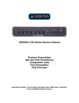
1
IC30 Series Service Manual
Product Description
Set-Up/Test Procedures
Component Lists
Full Schematics
PCB Overlays
Australian Monitor. Private Bag 149 Silverwater NSW 1811. Australia
www.australianmonitor.com.au
IC30
Circuit Description
The IC30 is a 30 watt mixer amplifier which operates on 230/240 VAC, 50Hz or 12 VDC via an external
DC power supply source. The amplifier is supplied free standing with rubber feet but can be rack mounted
via an optional rack mount kit (IC30RMK). The IC30 will deliver 30 watts into a load of 4 ohms, 70 volt or
100 volt line. The IC30 may be stacked to a maximum of four units high. An IEC type mains cord and
receptacle are provided, the receptacle also houses the mains fuse in a drawer which pulls open to expose
the fuse. A single spare fuse is also located in this drawer.
AC Power Inlet
The 3 pin IEC power inlet is located on the bottom left of the rear panel and accepts a standard mains
power lead fitted with an IEC connector. Before plugging in a power lead, please check the rear panel of
the amplifier to ensure that the voltage switch is set correctly for your part of the world.
The operating voltage is 230/240 VAC @ 50 Hz. The inlet is equipped with an inbuilt AC fuse holder fitted
with a 1 amp plus a spare within the holder].
Power consumption is approximately 60 VA.
12 Volt DC Operation
The IC30 features optional 12VDC power to run off a battery supply if required. This is connected via the
rear terminal strip. The front panel Power Switch will not switch DC power ‘on’ or ‘off’ in DC operation.
In this mode the amplifier is always ‘on’. When running from 12 VDC power, the LED will not illuminate.
There is no trickle charge resistor across the diode.
230V/240V Slide Switch
The operating voltage of the amplifier is user selectable between 230V and 240V via a slide switch located
on the top left side of the rear panel. This switch should be set to match the AC voltage of your country.
The mains transformer is wound with a 230V winding plus a 10V winding internally connected.
Power Amp
The IC30 uses two(2) Philips amplifier ICs (TDA1516) with built in current overload and thermal
protection. The two amplifier modules are capacitively coupled to the two primary windings of the output
transformer in parallel (not in bridge).
Speaker Output Terminal Strip
The screw terminals in the middle of the strip allow access to the direct speaker outputs of the amplifier.
Reading from left to right the terminals are:
COM
4
Common or “-” for low impedance speaker loads (4 or 8 ohms).
Positive “+” for 4 ohm speaker loads (use with common)
COM
70
100
Common or “-” for 70v or100v speaker loads (maximum load of 80 ohms at 100v)
Positive “+” for 70v line speaker loads (use with common)
Positive “+” for 100v line speaker loads (use with common)
Please ensure that the correct “Common” is used. Low impedance and 70/100v loads can be used
simultaneously but please pay careful attention to the overall speaker load.
Note: The minimum impedance (or maximum load) at 100 volt line should be no less than 80 Ohms
Muting
The last two(2) terminals on the barrier strip are for muting. Channels 2 and 3 are muted when the two
mute contacts are shorted together. The muting is done by a FET switch so there is no ramping. An optional
VOX muting module (TX3010) is also available with has ramping.
Phantom Power
The IC30 does not have phantom power on the XLR’s.
Tape Output
A mono RCA output connector provides a line level output with a maximum of 350mV into 10k Ohms.
Signal from all three input channels are fed to the tape output. Level adjustments made to the three input
channels will affect the level going to the tape output.
Microphone/Line Inputs
Three universal microphone/line inputs are provided. Microphone inputs are via the 3 pin XLR connectors
while line inputs are via the RCA style connectors (one of each is provided per channel). All three inputs
can be used for microphone and auxiliary input sources. It is also possible to connect both a microphone
and line/aux source to the one channel simultaneously however their relative levels to one another will be
fixed, as there is only one gain control per channel.
The XLR connectors are wired: Pin 1: Earth. Pin 2: Active (high, +), Pin 3: Active (low, -). Microphone
input sensitivity is 1.5mV at 200 ohms.
The RCA connectors have an input sensitivity of 80mV at 47K ohms.
Microphone Inputs
All three(3) inputs are dual mic/line with microphone inputs being via a 3 pin XLR connector per channel.
The mic input sensitivity is 1.5mV @ 200 ohms. Pin connections are: pin 1-earth; pin 2-signal (hot +); pin
3-signal (cold -). Phantom power is not available. Reading from left to right across the rear panel, the inputs
are 3, 2, & 1.
Line Inputs
All three(3) inputs are dual mic/line with line/auxiliary inputs being via mono RCA connectors per channel.
Line input sensitivity is 75mV @ 47K ohms. Reading from left to right across the rear panel, the inputs are
3, 2, & 1.
Optional Accessories
Tone Generators
Four separate tones are available as an optional plug in card (ATC5488). The ATC5488 is a small circuit
board which simply plugs into a socket inside the amplifier. Activation is via contact closures which may
be wired to the rear panel of the IC30 or to external switches or a timer. Full installation instructions are
provided with the tone generator.
Tones available on the ATC5488 tone generator board are:
Evacuation Tone (to Australian Standard AS2220.1.2)
Alert Tone (to Australian Standard AS2220.1.2)
Bell TonePre Announce Chime
VOX Muting Module
An optional VOX muting module (TX3010) is available. When installed inside the amplifier, signal on
channel 1 of the amplifier will automatcially mute channels 2 and 3. When there is no signal on channel 1,
channels 2 and 3 will operate normally. Full installation instructions are provided with the TX3010.
Rack Mouting Kit
An optional rack mounting kit (IC30RMK) is available to mount the IC30 in a standard 19" equipment
rack.
Fuse Sizes
Mains 230 VAC: 1 Amperes Slow Blow
The DC fuse is located on the circuit board. This is a feature of the AMIS series amplifiers, which are
equipped with a current limiting circuit preventing excessive DC currents, thus eliminating the risk of
blowing high tension fuses. In the unlikely event that the DC fuse actuates, the output IC modules should
be checked, as it is probable that the amplifier has been subjected to very extreme conditions. The DC fuses
are 4A time lag fuses.
C24
1u
C25
LM1458
C5
1u
R13
C10
1u
+5V
R42
50K
2
C13
1u
7
5
R14
4K7
R32
10K
1
R15
47K
C11
330P
AUX3
C15
1u
R19
680R
C16
1u
R23
R31
6K8
1
2
R45
1K
3
IC3C
4066
7
1
3
C18
330P
R21
22K
+5V
B
C21
1u
R24
4K7
4
R22
10R
R25
47K
100V
C
4 OHM
R17
10K
10
11
8
+14VDC
C34
47u
10R
6 R44
IC6
4 LM741
C30
0.47
C
13
IC4
C22
1u
+10V
R29
10K
C19
1u
C47
10u
9
1
+12V
C50
10u
5
TDA1516
2
4
IC2A
2
C49
470u
68K
R41
+5V
5
LM1458
C17
1u
8
R20
680R
C
70V
C33
47u
4
MIC3
9
C36
82P
C37
1u
3
T2
IC5
TDA1516
R34
6K8
R48
1M
22K
C46
10u
5
2
+10V
C20
330P
C45
10u
C29
1200P
R12
22K
+5V
R18
47k
13
R33
1K
R43
50K
C
C31
0.47
R30
10K
PIN 14 4066
IC3A
4066
IC1B
6
R47
10K
R39
0R
C28
0.03
R26
1K
C14
1u
22K
LM1458
C23
1u
C27
1u
12
R16
100R
D
7
10
R11
680R
+10V
+5V C12
330P
C9
1u
IC2B
6
12
MIC2
C8
1u
+10V
13
R10
680R
R4
22K
R8 P2
47K
C35
47u
TAPE OUT
100P
5
R5
10R
8
R9
47k
AUX2
R7
4K7
C26
1u
4
3
C4
330P
C7
1u
1
R40
68K
R27
47K
11
IC1A
2
8
+14VDC
7
22K
LM1458
C3
1u
7
X7
X5
GRD
4
R3
680R
D
6
7
R6
R49
100R
5
10R +14VDC
6
C2
1u
MIC1
4
R50
3
R2
680R
3
C6
330P
6
AUX1
C1
1u
8
2
R1
47k
3
1
C32
47u
P1
R28
0R
D1
MUTE
F2 4A SB
B
+14V
+12V
BATTERY
F1
0.5A SB
S1
R38
10R
T1
V1
BD139
D2-D5
N1
R35
4K7
C40
C41
+10V
C43
100u
R36
1K
D6
11V
C42
470u
+5V
R37
1K
2200u
2200u
A
C39
2200u
C38
2200u
240VAC
A
C44
47u
Title
Size
A3
Date:
File:
1
2
3
4
5
6
IC30 MIX/POWER PCB
CD6168-1
D
Number
4-Jul-2003
C:\AMIS604 Manual\CD6168-1.DDB
7
Revision
Sheet of
Drawn By:
1
8
SBG
1
IC30 Parts List
Designator
C1
C10
C11
C12
C13
C14
C15
C16
C17
C18
C19
C2
C20
C21
C22
C23
C24
C25
C26
C27
C28
C29
C3
C30
C31
C32
C33
C34
C35
C36
C37
C38
C39
C4
C40
C41
C42
C43
C44
C45
C46
C47
C49
C5
C50
C6
C7
C8
C9
D1
D2-D5
D6
F1
Part Type
1u
1u
330P
330P
1u
1u
1u
1u
1u
330P
1u
1u
330P
1u
1u
1u
1u
100P
1u
1u
0.03
1200P
1u
0.47
0.47
47u
47u
47u
47u
82P
1u
2200u
2200u
330P
2200u
2200u
470u
100u
47u
10u
10u
10u
470u
1u
10u
330P
1u
1u
1u
12V
.5A
Description
Electrolytic capacitor 63V
Electrolytic capacitor 63V
Multi layer ceramic capacitor 100V
Multi layer ceramic capacitor 100V
Electrolytic capacitor 63V
Electrolytic capacitor 63V
Electrolytic capacitor 63V
Electrolytic capacitor 63V
Electrolytic capacitor 63V
Multi layer ceramic capacitor 100V
Electrolytic capacitor 63V
Electrolytic capacitor 63V
Multi layer ceramic capacitor 100V
Electrolytic capacitor 63V
Electrolytic capacitor 63V
Electrolytic capacitor 63V
Electrolytic capacitor 63V
Multi layer ceramic capacitor 100V
Electrolytic capacitor 63V
Electrolytic capacitor 63V
Multi layer ceramic capacitor 100V
Multi layer ceramic capacitor 100V
Electrolytic capacitor 63V
Metalised Poly Capacitor
Electrolytic capacitor 63V
Electrolytic capacitor 35V
Electrolytic capacitor 35V
Electrolytic capacitor 35V
Electrolytic capacitor 35V
Multi layer ceramic capacitor 100V
Electrolytic capacitor 63V
Electrolytic capacitor 35V
Electrolytic capacitor 35V
Multi layer ceramic capacitor 100V
Electrolytic capacitor 35V
Electrolytic capacitor 35V
Electrolytic capacitor 35V
Electrolytic capacitor 100V
Electrolytic capacitor 35V
Electrolytic capacitor 50V
Electrolytic capacitor 50V
Electrolytic capacitor 50V
Electrolytic capacitor 35V
Electrolytic capacitor 63V
Electrolytic capacitor 50V
Multi layer ceramic capacitor 100V
Electrolytic capacitor 63V
Electrolytic capacitor 63V
Electrolytic capacitor 63V
Diode 1N5408
Diode 1N5408
Zener Diode 1W 12V 1N4742
0.5 Amp Anti-surge Fuse
Manufacturer's Code
2121280010
2121280010
2127181331
2127181331
2121280010
2121280010
2121280010
2121280010
2121280010
2127181331
2121280010
2121280010
2127181331
2121280010
2121280010
2121280010
2121280010
2127181101
2121280010
2121280010
2124292330
2127181122
2121280010
2124262472
2124262472
2121230470
2121230470
2121230470
2121230470
2127181820
2121280010
2121220222
2121220222
2127181331
2121220222
2121220222
2121230471
2121220101
2121230470
2121250100
2121250100
2121250100
2121230471
2121280010
2121250100
2127181331
2121280010
2121280010
2121280010
2133450408
2133450408
2136010120
2543210059
F2
IC1
IC2
IC3
IC4
IC5
IC6
P1
P2
R1
R10
R11
R12
R13
R14
R15
R16
R17
R18
R19
R2
R20
R21
R22
R23
R24
R25
R26
R27
R28
R29
R3
R30
R31
R32
R33
R34
R35
R36
R37
R38
R39
R4
R40
R41
R42
R43
R44
R45
R47
R48
R49
R5
R50
R6
4.0A
LM1458
LM1458
4066
TDA1516
TDA1516
LM741
X7
X5
47k
680R
680R
22K
22K
4K7
50K
100R
10K
47k
680R
680R
680R
22K
10R
22K
4K7
50K
1K
47K
0R
10K
680R
10K
6K8
10K
1K
6K8
4K7
1K
1K
10R
0R
22K
68K
68K
50K
50K
10R
1K
10K
1M
100R
10R
10R
22K
4.0 Amp Anti-surge Fuse
IC Dual Op Amp DIP8
IC Dual Op Amp DIP8
I.C. CD 4066BCN VCA (14 PIN)
Amplifier IC TDA1516BQ
Amplifier IC TDA1516BQ
LM741 IC
Transistor BD139
Transistor BD139
Resistor, metalfilm .5W
Resistor, metalfilm .5W
Resistor, metalfilm .5W
Resistor, metalfilm .5W
Resistor, metalfilm .5W
Resistor, metalfilm .5W
Potentiometer linear
Resistor, metalfilm .5W
Resistor, metalfilm .5W
Resistor, metalfilm .5W
Resistor, metalfilm .5W
Resistor, metalfilm .5W
Resistor, metalfilm .5W
Resistor, metalfilm .5W
Resistor, metalfilm .5W
Resistor, metalfilm .5W
Resistor, metalfilm .5W
Potentiometer linear
Resistor, metalfilm .5W
Resistor, metalfilm .5W
Resistor, metalfilm .5W
Resistor, metalfilm .5W
Resistor, metalfilm .5W
Resistor, metalfilm .5W
Resistor, metalfilm .5W
Resistor, metalfilm .5W
Resistor, metalfilm .5W
Resistor, metalfilm .5W
Resistor, metalfilm .5W
Resistor, metalfilm .5W
Resistor, metalfilm .5W
Resistor, metalfilm .5W
Resistor, metalfilm .5W
Resistor, metalfilm .5W
Resistor, metalfilm .5W
Resistor, metalfilm .5W
Potentiometer linear
Resistor, metalfilm .5W
Resistor, metalfilm .5W
Resistor, metalfilm .5W
Resistor, metalfilm .5W
Resistor, metalfilm .5W
Resistor, metalfilm .5W
Resistor, metalfilm .5W
Resistor, metalfilm .5W
Resistor, metalfilm .5W
2541210840
2152870558
2152870558
2159440066
2153121516
2153121516
2152080741
2141400139
2141400139
9111590473
9111590681
9111590681
9111590223
9111590223
9111590472
2021000503
9111590101
9111590103
9111590473
9111590681
9111590681
9111590681
9111590223
9111590100
9111590223
9111590472
2021000503
9111590102
9111590473
9111590000
9111590103
9111590681
9111590103
9111590682
9111590103
9111590102
9111590682
9111590472
9111590102
9111590102
9111590100
9111590000
9111590223
9111590683
9111590683
2021000503
2021000503
9111590100
9111590102
9111590103
9111590104
9111590101
9111590100
9111590100
9111590223
R7
R8
R9
S1
4K7
50K
47k
Resistor, metalfilm .5W
Potentiometer linear
Resistor, metalfilm .5W
Rocker switch SPST
9111590472
2021000503
9111590473
2511213112
WORK INSTRUCTION
Testing of IC 30
1. Perform physical inspection ( Visual Inspection stage )
1.1 Check :
• All screws for tightness ( esp. H/S & IC fixing).
• Capacitors for polarity.
• Earth connection for good contact (XLR gnd to AC earth), including earthing of
RCA’s,
• All wiring points for good contacts (Soldering and Crimping)
2. Set up amplifier for test (Pre (PCB testing) ).
2.1 Connect amplifier to :
• Variac (0 Vac)
• Signal generator (Mic 1, no signal),
• Resistive load (4ohm on 4ohm output).
2.2 Reset controls :
• Volume controls to minimum,
• Bass/treble control to center,
• Phantom power switch to off,
3. Power up (Pre (PCB testing).
3.1 Turn on power switch and adjust voltage to 120VAC. Watch current meter for
excess current draw.
3.2 Check DC power supply at fuse. Should be approximately. 7V ( + 1V )
3.3 Check DC voltage on mixer board. Should be approximately. 6V (Check on 8 No.
Pin of 1458).
3.4 Adjust variac to 240VAC. Check DC power supply. Should be approx. 15V
(+ 1V) loaded, no load (16.5V + 1V).
3.5 Check DC voltage on mixer board. Should be approx. (11V + 1V).
4. AC Check (Final stage).
4.1 Set signal generator to (1mV) + 0.2mV. Turn up Mic1 volume control to full.
Watch for irregularities with output. Check sensitivity of input. – MIC 1mV
(+ 0.2mV) in 10.5Vrms out (2.6% THD).
4.2 Measure 100V line, 70V line, tol. 5%
4.3 Check tape output (0.4V + 100mV).
4.4 Check Bass control @100HZ = + 12dB (can get only upto 8V O/P with total swing
of (20 – 24dB) ) and treble @10KHz = + 10dB (tolerance. 10%) total swing (18 –
22dB).
5. Function Checks (Final stage).
5.1 Move signal generator to Mic2. Turn up volume control. Watch for irregularities.
Check for 10.5V out.
5.2 Move signal generator to Mic3. Turn up volume control. Watch for irregularities.
Check for 10.5V out.
6. Line level inputs (Final stage).
6.1 Connect signal generator to Line1 input. Check input sensitivity – LINE (85mV +
20mV) in 10.5V out.
6.2 Move signal generator to Line2 input. Check 10.5V out.
6.3 Move signal generator to Line3 input. Check 10.5V out.
6.4 Check muting function by shorting mute terminals on rear barrier strip.
6.5 Check operation of (230 – 240)V selector switch for full wattage in each position
of switch.
6.6 Frequency Response – Check the frequency response and power bandwidth of 1st
set of every new batch of production.
Frequency Response – (250Hz – 10kHz).
Power band – (250Hz – 6.5kHz).
7. Finishing up (Final stage).
7.1 Short output and check that signal cuts out and returns after short is removed.
7.2 Remove input signal and check for Hum and Noise (<20m Vrms)
7.3 Connect 12V DC to rear barrier strip, turn off power switch. Check signal remains.
7.4 Reset volumes to minimum.
7.5 Disconnect from test bench and inspect for scratches on external paint.
8. Burn In.
8.1 Leave units on (with lid) for 24 hrs.
9. Sound Test (Check Fuse Ratings).
9.1 Adjust tone controls to minimum. and maximum listening for scratches and
irregularities. Similarly for each level control with MASTER full.
9.2 Connect CD player to Line4 and bring up channel and master volumes.
9.3 Listen for irregularities.
9.4 Check priority of (MIC1 and MIC2) over all other channels.
9.5 Check all the tones.
WORK INSTRUCTION
Testing of IC 30
1. Perform physical inspection ( Visual Inspection stage )
1.1 Check :
• All screws for tightness ( esp. H/S & IC fixing).
• Capacitors for polarity.
• Earth connection for good contact (XLR gnd to AC earth), including earthing of
RCA’s,
• All wiring points for good contacts (Soldering and Crimping)
2. Set up amplifier for test (Pre (PCB testing) ).
2.1 Connect amplifier to :
• Variac (0 Vac)
• Signal generator (Mic 1, no signal),
• Resistive load (4ohm on 4ohm output).
2.2 Reset controls :
• Volume controls to minimum,
• Bass/treble control to center,
• Phantom power switch to off,
3. Power up (Pre (PCB testing).
3.1 Turn on power switch and adjust voltage to 230VAC. Watch current meter for
excess current draw.
3.2 Check DC power supply at fuse. Should be approximately. 7V ( + 1V )
3.3 Check DC voltage on mixer board. Should be approximately. 6V (Check on 8 No.
Pin of 1458).
3.4 Adjust variac to 240VAC. Check DC power supply. Should be approx. 15V
(+ 1V) loaded, no load (16.5V + 1V).
3.5 Check DC voltage on mixer board. Should be approx. (11V + 1V).
4. AC Check (Final stage).
4.1 Set signal generator to (1mV) + 0.2mV. Turn up Mic1 volume control to full.
Watch for irregularities with output. Check sensitivity of input. – MIC 1mV
(+ 0.2mV) in 10.5Vrms out (2.6% THD).
4.2 Measure 100V line, 70V line, tol. 5%
4.3 Check tape output (0.4V + 100mV).
4.4 Check Bass control @100HZ = + 12dB (can get only upto 8V O/P with total swing
of (20 – 24dB) ) and treble @10KHz = + 10dB (tolerance. 10%) total swing (18 –
22dB).
5. Function Checks (Final stage).
5.1 Move signal generator to Mic2. Turn up volume control. Watch for irregularities.
Check for 10.5V out.
5.2 Move signal generator to Mic3. Turn up volume control. Watch for irregularities.
Check for 10.5V out.
6. Line level inputs (Final stage).
6.1 Connect signal generator to Line1 input. Check input sensitivity – LINE (85mV +
20mV) in 10.5V out.
6.2 Move signal generator to Line2 input. Check 10.5V out.
6.3 Move signal generator to Line3 input. Check 10.5V out.
6.4 Check muting function by shorting mute terminals on rear barrier strip.
6.5 Check operation of (230 – 240)V selector switch for full wattage in each position
of switch.
6.6 Frequency Response – Check the frequency response and power bandwidth of 1st
set of every new batch of production.
Frequency Response – (250Hz – 10kHz).
Power band – (250Hz – 6.5kHz).
7. Finishing up (Final stage).
7.1 Short output and check that signal cuts out and returns after short is removed.
7.2 Remove input signal and check for Hum and Noise (<20m Vrms)
7.3 Connect 12V DC to rear barrier strip, turn off power switch. Check signal remains.
7.4 Reset volumes to minimum.
7.5 Disconnect from test bench and inspect for scratches on external paint.
8. Burn In.
8.1 Leave units on (with lid) for 24 hrs.
9. Sound Test (Check Fuse Ratings).
9.1 Adjust tone controls to minimum. and maximum listening for scratches and
irregularities. Similarly for each level control with MASTER full.
9.2 Connect CD player to Line4 and bring up channel and master volumes.
9.3 Listen for irregularities.
9.4 Check priority of (MIC1 and MIC2) over all other channels.
9.5 Check all the tones.