1
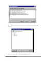
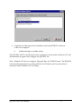
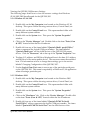
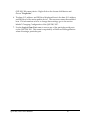
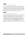
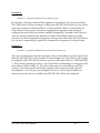
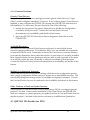
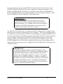
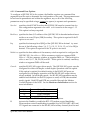
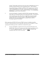
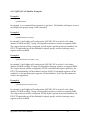
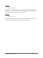
QSP-200/300
Four Channel Asynchronous
RS-422/485 PCMCIA Adapter
INTERFACE CARDS FOR PERSONAL COMPUTERS
User's Manual
Quatech, Inc.
662 Wolf Ledges Parkway
Akron, Ohio 44311
QSP-200/300 User's Manual
TEL: (330) 434-3154
FAX:(330) 434-1409
WWW:quatech.com
Warranty Information
Quatech Inc. warrants the QSP-200/300
to be free of defects for five (5) years
from the date of purchase. Quatech Inc. will repair or replace any adapter that fails to
perform under normal operating conditions and in accordance with the procedures
outlined in this document during the warranty period. Any damage that results from
improper installation, operation, or general misuse voids all warranty rights.
The authors have taken due care in the preparation of this document and any
associated software program(s). In no event will Quatech Inc. be liable for damages of
any kind, incidental or consequential, in regard to or arising out of the performance or
form of the materials presented herein and in the program(s) accompanying this
document. No representation is made regarding the suitability of this product for any
particular purpose.
Quatech Inc. reserves the right to edit or append to this document or the product(s) to
which it refers at any time and without notice.
Please complete the following information and retain for your records. Have this
information available when requesting warranty service.
Date of purchase:
Model Number:
QSP-200/300
Product Description:
Four Channel RS-422/485 PCMCIA
Adapter
Serial Number:
The information contained in this document cannot be reproduced in any form without
the written consent of Quatech, Inc. Likewise, any software programs that might
accompany this document can be used only in accordance with any license
agreement(s) between the purchaser and Quatech, Inc. Quatech, Inc. reserves the right
to change this documentation or the product to which it refers at any time and without
notice.
The authors have taken due care in the preparation of this document and every attempt
has been made to ensure its accuracy and completeness. In no event will Quatech, Inc.
be liable for damages of any kind, incidental or consequential, in regard to or arising
out of the performance or form of the materials presented in this document or any
software programs that might accompany this document.
Quatech, Inc. encourages feedback about this document. Please send any written
comments to the Technical Support department at the address listed on the cover page
of this document.
Copyright ©2002
Quatech Inc.
662 Wolf Ledges Parkway
Akron, Ohio 44311
All rights reserved. Printed in the U.S.A.
Trademarks:
Quatech is a trademark of Quatech Inc. Other product and company names are registered
trademarks or trademarks of their respective holders.
Compliances - Electromagnetic Emissions
EC - Council Directive 89/336/EEC
This equipment has been tested and found to comply with the limits of the following standards for a digital
device:
? EN50081-1
(EN55022, EN60555-2, EN60555-3)
? EN50082-1
(IEC 801-2, IEC 801-3, IEC 801-4)
Type of Equipment:
Information Technology Equipment
Equipment Class:
Commercial, Residential, & Light Industrial
FCC - Class B
This equipment has been tested and found to comply with the limits for a Class B digital device, pursuant to
part 15 of the FCC Rules. These limits are designed to provide reasonable protection against harmful
interference in a residential installation. This equipment generates, uses and can radiate radio frequency
energy and if not installed and used in accordance with the instructions, may cause harmful interference to
radio communications. However, there is no guarantee that interference will not occur in a particular
installation, If this equipment does cause harmful interference to radio or television reception, which can be
determined by turning the equipment off and on, the user is encouraged to try to correct the interference by
one or more of the following measures:
? Reorient or relocate the receiving antenna.
? Increase the separation between the equipment and receiver.
? Connect the equipment into an outlet on a circuit different from that to which the receiver is
?
connected.
Consult the dealer or an or an experienced radio/TV technician for help.
This equipment has been certified to comply with the limits for a Class B computing device, pursuant to
FCC Rules. In order to maintain compliance with FCC regulations, shielded cables must be used with this
equipment. Operation with non-approved equipment or unshielded cables is likely to result in interference
to radio and TV reception. The user is cautioned that changes and modifications made to the equipment
without the approval of the manufacturer could void the user's authority to operate this equipment.
Table of Contents
1 Introduction . . . . . . . . . . . . . . . . . . . . . . . . . . . . . . . . . . . . . . . . . . . . . . . . . . . . . . . . . . . . . 2
2 Windows 95/98/ME/2000/NT Installation . . . . . . . . . . . . . . . . . . . . . . . . . . . . . . . 3
2.1 Installing a Quatech QSP-200/300 Under Windows 95/98/ME/2000 . . 4
2.1.1 Windows 95/98 . . . . . . . . . . . . . . . . . . . . . . . . . . . . . . . . . . . . . . . . . . . . . . . 4
2.1.2 Window Millennium (ME) . . . . . . . . . . . . . . . . . . . . . . . . . . . . . . . . . . . . . 4
2.1.3 Windows 2000 . . . . . . . . . . . . . . . . . . . . . . . . . . . . . . . . . . . . . . . . . . . . . . . . 5
2.1.1 Installing QSP-200/300 Under Windows NT . . . . . . . . . . . . . . . . . . . . . . 5
2.1.4 Window 95/98/ME . . . . . . . . . . . . . . . . . . . . . . . . . . . . . . . . . . . . . . . . . . . 9
2.1.5 Windows 2000 . . . . . . . . . . . . . . . . . . . . . . . . . . . . . . . . . . . . . . . . . . . . . . . . 9
2.2 Changing Configuration of the QSP-200/300. . . . . . . . . . . . . . . . . . . . . . . . 11
2.2.1 Windows 95/98/ME . . . . . . . . . . . . . . . . . . . . . . . . . . . . . . . . . . . . . . . . . 11
2.2.2 Windows 2000 . . . . . . . . . . . . . . . . . . . . . . . . . . . . . . . . . . . . . . . . . . . . . . . 11
3 Windows CE . . . . . . . . . . . . . . . . . . . . . . . . . . . . . . . . . . . . . . . . . . . . . . . . . . . . . . . . . . . 14
4 DOS / Windows 3.x Installation . . . . . . . . . . . . . . . . . . . . . . . . . . . . . . . . . . . . . . . . . 16
4.1 QSP-200/300 Client Driver for DOS . . . . . . . . . . . . . . . . . . . . . . . . . . . . . . . . . 17
4.1.1 Client Driver Installation . . . . . . . . . . . . . . . . . . . . . . . . . . . . . . . . . . . . . . 17
4.1.2 Command Line Options . . . . . . . . . . . . . . . . . . . . . . . . . . . . . . . . . . . . . . 18
4.1.3 QSP-200/300 Client Driver Examples . . . . . . . . . . . . . . . . . . . . . . . . . . . 20
4.1.4 Common Problems . . . . . . . . . . . . . . . . . . . . . . . . . . . . . . . . . . . . . . . . . . . 23
4.2 QSP-200/300 Enabler for DOS . . . . . . . . . . . . . . . . . . . . . . . . . . . . . . . . . . . . . . 23
4.2.1 Command Line Options . . . . . . . . . . . . . . . . . . . . . . . . . . . . . . . . . . . . . . 25
4.2.2 QSP-200/300 Enabler Examples . . . . . . . . . . . . . . . . . . . . . . . . . . . . . . . . 27
4.2.3 Common Problems . . . . . . . . . . . . . . . . . . . . . . . . . . . . . . . . . . . . . . . . . . . 29
5 OS/2 Installation . . . . . . . . . . . . . . . . . . . . . . . . . . . . . . . . . . . . . . . . . . . . . . . . . . . . . . . 30
5.1 Command Line Options . . . . . . . . . . . . . . . . . . . . . . . . . . . . . . . . . . . . . . . . . . . . 31
5.1.1 Configuring With "System Assigned" Resources . . . . . . . . . . . . . . . . . 31
5.1.2 Configuring With "User Assigned" Resources . . . . . . . . . . . . . . . . . . . . 32
5.1.3 Advanced Configuration Topics . . . . . . . . . . . . . . . . . . . . . . . . . . . . . . . 33
5.2 Monitoring The Status Of PCMCIA Cards . . . . . . . . . . . . . . . . . . . . . . . . . . . 34
5.3 Common Problems . . . . . . . . . . . . . . . . . . . . . . . . . . . . . . . . . . . . . . . . . . . . . . . . . 35
6 Hardware Information . . . . . . . . . . . . . . . . . . . . . . . . . . . . . . . . . . . . . . . . . . . . . . . . . . 36
6.1 Port Addressing . . . . . . . . . . . . . . . . . . . . . . . . . . . . . . . . . . . . . . . . . . . . . . . . . . . 36
6.2 Scratchpad / Interrupt Status Register . . . . . . . . . . . . . . . . . . . . . . . . . . . . . . 36
6.3 Auxiliary Channel Configuration . . . . . . . . . . . . . . . . . . . . . . . . . . . . . . . . . . . 37
6.3.1 Auxiliary Channel: RTS-CTS Handshaking . . . . . . . . . . . . . . . . . . . . . . 37
6.3.2 Auxiliary Channel: Handshaking Disabled . . . . . . . . . . . . . . . . . . . . . . 38
6.4 Termination Resistors . . . . . . . . . . . . . . . . . . . . . . . . . . . . . . . . . . . . . . . . . . . . . . 39
6.5 2-Wire Operation . . . . . . . . . . . . . . . . . . . . . . . . . . . . . . . . . . . . . . . . . . . . . . . . . . 39
7 External Connections . . . . . . . . . . . . . . . . . . . . . . . . . . . . . . . . . . . . . . . . . . . . . . . . . . . 41
8 Specifications . . . . . . . . . . . . . . . . . . . . . . . . . . . . . . . . . . . . . . . . . . . . . . . . . . . . . . . . . . . 43
QSP-200/300 User's Manual
This Page Left Blank Intentionally
QSP-200/300 User's Manual
1
1 Introduction
The Quatech QSP-200/300 provides four independent RS-422/485 asynchronous serial
communications interfaces for systems equipped with PCMCIA Type II and/or Type III
expansion sockets. The QSP-200/300 is a PCMCIA Type II (5 mm) card and is PCMCIA
PC Card Standard Specification 2.1 compliant.
The QSP-200/300's serial ports are implemented using 16C550 Universal Asynchronous
Receiver/Transmitters (UARTs) which are the recommended communications interface
for multitasking environments and with applications involving high data transfer rates.
The QSP-200/300's four serial ports are addressed in a single 32 byte I/O block for
simplified programming and all four channels share a common interrupt (IRQ). A
special interrupt status register is also available to simplify the software required to
service multiple serial ports in an interrupt driven environments.
QSP-200/300 User's Manual
2
2 Windows 95/98/ME/2000/NT Installation
Windows 95/98 maintains a registry of all known hardware installed within the
computer. Inside this hardware registry Windows 95/98 keeps track of all the
computer's resources, such as base I/O addresses, IRQ levels, and DMA channels. In
the case of a PC Card (PCMCIA) type board, Windows 95/98 configures the new
hardware using free resources it finds within the hardware registry, and updates the
registry automatically.
Windows 95/98 handles the QSP-200/300 as a "parent/child device". The
QSP-200/300 is the "parent device". Each serial port is a "child device" of this "parent
device". To allow easy configuration of Quatech's QSP-200/300, two configuration
files have been written. These files are called "INF" files. The "QSP-200.INF" file
describes the resources of the QSP-200/300 parent device and indicates the number of
child devices. There are 4 child COM ports for the QSP-200/300. The
"MLTPT_SP.INF" file describes the settings for each serial port including all the
necessary device drivers.
Windows 95/98 allows changes in the system resources if the default choices are
unacceptable. But first, allow Windows 95/98 to configure all of the devices. Since
the child COM ports are dependent on the parent devices resource allocations, the
resources can only be modified at the parent device. Changing these resources is an
easy task described in a later section.
QSP-200/300 User's Manual
3
2.1 Installing a Quatech QSP-200/300 Under Windows
95/98/ME/2000
2.1.1 Windows 95/98
1. Insert the QSP-200/300 into any available PC Card socket.
2. The first time a new PC Card is installed the Add New Hardware Wizard
window opens. After the first installation, Windows 95/98 will
automatically detect and configure the card. If the Add New Hardware
Wizard window does not open, then skip to the next section, "Viewing the
QSP-200/300 Settings".
3. The Add New Hardware Wizard window provides several options to
configure the QSP-200/300 card. Click the "Driver from Disk" option
button. Click "OK" to continue.
4. Insert the QSP-200/300 Quatech COM CD into the drive, select the correct
drive letter, and click "OK". Windows 95/98 will browse for the
aforementioned files.
5. During the installation process, it may be required to supply the computer
with the Windows 95/98 CD. Insert the CD when prompted and click "OK"
.
IMPORTANT NOTE:
If the user has previously used any of the PC's COM ports
and the Windows 95/98 installation CD is not available, the
user may be able to skip this step. When prompted for the
Windows installation CD, click the "Skip" button to abort
copying of the serial communication drivers. If these drivers
are already present on the PC, the currently installed drivers
will be used.
6. The QSP-200/300 PC Card should now be configured. In the future,
Windows 95/98 will automatically recognize and configure the
QSP-200/300.
2.1.2 Window Millennium (ME)
1. Insert Quatech COM driver CD into the CD-ROM
2. Insert the QSP-200/300 into any available PC Card socket.
QSP-200/300 User's Manual
4
3. The ‘Add New Hardware Wizard’ will open. Select ‘Automatic search
for a better driver’
Windows Millennium will automatically search a install the correct driver for this
device.
2.1.3 Windows 2000
1. Insert Quatech COM driver CD into the CD-ROM
2. Insert the QSP-200/300 into any available PC Card socket.
Windows 2000 will automatically install the driver for this device.
2.1.1 Installing QSP-200/300 Under Windows NT
To allow easy configuration of the QSP-200/300 the Quatech Device Manager for
Windows NT has been written for the hardware. This configuration utility supports the
QSP-200/300 only in block addressing mode.
To begin the installation, open Windows Explorer and search for the ‘Setup.exe’
command to install the Quatech Device Manager. <See following Windows Explorer
figure.> (D:\Serial Port Adapters\Drivers\Windows NT 4.0 for PCI, PCMCIA,ISA).
Once the installation is complete an icon will be placed on the desktop.
Windows NT Exporer
QSP-200/300 User's Manual
5
1. Locate and double click the Quatech Device Manager icon on the desktop.
Device Manager Icon on Desktop
QSP-200/300 User's Manual
6
2.
Click the ‘Add’ button at the bottom of the Quatech Device Manager
Window.
3. Follow the steps for the ‘Add Quatech Hardware Wizard’.
QSP-200/300 User's Manual
7
4. Complete the final steps of the installation, insert the PCMCIA Card and
re-boot the computer.
v
Additional help is availabe online
The QSP-200/300 PC Card should now be configured. In the future, Windows NT will
automatically recognize and configure the QSP-200/300.
Note: Windows NT does not support ‘Plug and Play’ for PCMCIA cards. The PCMCIA
Card must be inserted prior to starting Windows NT and can not be removed and
reinserted while Windows NT is running.
QSP-200/300 User's Manual
8
Viewing the QSP-200/300 Resource Settings
The following steps detail how to view the resource settings that Windows
95/98/ME/2000 has allocated for the QSP-200/300.
2.1.4 Window 95/98/ME
1. Double click on the My Computer icon located on the Windows 95/98
desktop. This opens a folder showing various drives, Control Panel, etc.
2. Double click on the Control Panel icon. This opens another folder with
many different system utilities.
3. Double click on the System icon. This opens the "System Properties"
window.
4. Click on the "Device Manager" tab. Double click on the item "Ports (Com
& LPT)" located within the list of hardware.
5. Double click on any of the items labeled "Quatech Multi- port(COM x)"
where x represents the logical COM port number. The items labeled
"Quatech Multi-port" are the child devices of the QSP-200/300 parent
device. Click the "Resources" tab at the top of the "System Properties" box.
6. The base I/O address and IRQ level displayed here is the base I/O address
and IRQ level of the entire parent device. The resources cannot be modified
here. For information on how to change these settings, got to the section
labeled "Changing Configuration of the QSP-200/300".
7. Use the Logical Com Port name to access any of the particular serial ports
on the QSP-200/300. This name is required by a Windows 95/98 application
when accessing a particular port.
2.1.5 Windows 2000
1. Double click on the My Computer icon located on the Windows 2000
desktop. This opens a folder showing various drives, Control Panel, etc.
2. Double click on the Control Panel icon. This opens another folder with
many different system utilities.
3. Double click on the System icon. This opens the "System Properties"
window.
4. Click on the "Hardware" tab. Click on the ‘Device Manager’. Double click
on the item "Ports (Com & LPT)" located within the list of hardware.
5. Double click on any of the items labeled "Quatech PCMCIA Serial
Port(COM x)" where x represents the logical COM port number. The items
labeled "Quatech PCMCIA Serial Port" are the child devices of the
QSP-200/300 User's Manual
9
QSP-200/300 parent device. Right click on the chosen child device and
choose "Properties".
6. The base I/O address and IRQ level displayed here is the base I/O address
and IRQ level of the entire parent device. The resources cannot be modified
here. For information on how to change these settings, got to the section
labeled "Changing Configuration of the QSP-200/300".
7. Use the Logical Com Port name to access any of the particular serial ports
on the QSP-200/300. This name is required by a Windows 2000 application
when accessing a particular port.
QSP-200/300 User's Manual
10
2.2 Changing Configuration of the QSP-200/300.
To change the hardware configuration of the QSP-200/300, follow the instructions
below.
2.2.1 Windows 95/98/ME
1. Double click the My Computer icon located on the Windows 95/98/ME
desktop.
2. Double click on the Control Panel icon.
3. Double click the System icon inside the Control Panel folder. This will
open the System Properties box.
4. Click the Device Manager tab located along the top of the System
Properties box.
5. Double click on the device group "Quatech Comm Adapters". The
QSP-200/300 model name should appear in this list. If either the "Quatech
Comm Adapters" group or the QSP-200/300 model number does not
appear, contact Quatech Technical Support for further assistance.
6. Click on the QSP-200/300 item and then click on the button labeled
"Properties".
7. Un-check the box "use automatic settings". This keeps Windows from
changing the resource settings when the system is restarted.
8. Select a "Basic Configuration" from the list box. Each "Basic Configuration" is
associated with a specific set of handshake and output driver options as
listed in the table below (a functional description of these options are
contained in the section Hardware Information).
9. If a change in I/O address and / or IRQ setting is required, select the
resource to be modified (I/O or IRQ) and select "Change Settings". Make
the desired changes and then click on "OK". A shutdown of the system may
be required to allow the settings to change. If prompted for a shutdown,
select the option which restarts Windows 95.
10. The QSP-200/300 will be automatically reconfigured to the desired settings.
11. The card is now ready for use.
2.2.2 Windows 2000
1. Double click the My Computer icon located on the Windows 2000 desktop.
2. Double click on the Control Panel icon.
QSP-200/300 User's Manual
11
3. Double click the System icon inside the Control Panel folder. This will
open the System Properties box.
4. Click the Device Manager button located in the center of the System
Properties box.
5. Double click on the device group "Quatech Multiport Serial Devices". The
QSP-200/300 model name should appear in this list. If either the "Quatech
Comm Adapters" group or the QSP-200/300 model number does not
appear, contact Quatech Technical Support for further assistance.
6. Click on the ‘Quatech QSP-200/300 PCMCIA Four-Port RS-422/465
Serial Adapter’ item and then click on the button labeled "Properties".
7. Un-check the box "use automatic settings". This keeps Windows from
changing the resource settings when the system is restarted.
8. Select a "Basic Configuration" from the list box. Each "Basic Configuration" is
associated with a specific set of handshake and output driver options as
listed in the table below (a functional description of these options are
contained in the section Hardware Information).
9. If a change in I/O address and / or IRQ setting is required, select the
resource to be modified (I/O or IRQ) and select "Change Settings". Make
the desired changes and then click on "OK". A shutdown of the system may
be required to allow the settings to change. If prompted for a shutdown,
select the option which restarts Windows 95.
10. The QSP-200/300 will be automatically reconfigured to the desired settings.
11. The card is now ready for use.
QSP-200/300 User's Manual
12
Basic
Configuration
0000
0001
0002
0003
0004
0005
0006
0007
0008
0009
000A
000B
I/O
any
any
any
any
any
any
any
any
any
any
any
any
IRQ
any
any
any
any
any
any
any
any
any
any
any
any
Handshake Mode
loopback enabled
loopback enabled
loopback enabled
loopback disabled
loopback disabled
loopback disabled
loopback enabled
loopback enabled
loopback enabled
loopback disabled
loopback disabled
loopback disabled
Output Mode
always enabled
RTS controlled
DTR controlled
always enabled
RTS controlled
DTR controlled
always enabled
RTS controlled
DTR controlled
always enabled
RTS controlled
DTR controlled
Figure 1. Windows 95/98 configuration options.
QSP-200/300 User's Manual
13
3 Windows CE
The Quatech PCMCIA Windows CD installation copies a multiple device-specific
.cab files and the ini file to your desktop computer and launches the Application
Manger (which resides on the user's desktop computer as a result of installing
Active Sync) with the Application Manager .ini file as a parameter. This in turn
will install the driver onto the Windows CE connected device or if not connected
will install it on the next device connection to the desktop.
1.1Installing Quatech PCMCIA Cards under Windows CE
1. Connect and establish communication to the device to the desk to using
Active Sync (refer to Active Sync factory documentation
2. Locate and run the setup.exe file located in the Windows CE for PCMCIA
folder on the Quatech COM CD.
QSP-200/300 User's Manual
14
3. The setup program will copy the files to predetermined location, which can
be changed by the user. Click next to proceed.. Installation is now complete.
In the event that installation process took place with out having the Windows CE
device connected to the computer and the install program will prompt the user that
on the next on the next connection the device will complete the installation.
Choose ‘Yes’ on the following window and you installation is now complete .
QSP-200/300 User's Manual
15
4 DOS / Windows 3.x Installation
Two configuration software programs are provided with the QSP-200/300: a Client
Driver, QSP200CL.SYS, and a card Enabler, QSP200EN.EXE. Both of these programs
are executed from DOS (before entering Windows) and allow operation of the
QSP-200/300 in both the DOS and Windows 3.x environments. For optimal operation,
however, the Client Driver is the preferred method of installation and configuration.
The table below highlights the differences between these programs.
Client Driver (recommended)
Enabler (not recommended)
File name: QSP200CL.SYS
File name: QSP200EN.EXE
File type: DOS device driver
File type: DOS executable
Interfaces to PCMCIA Card and
Socket Services software (PCMCIA
host adapter independent)
Interfaces directly to Intel 82365SL
and other PCIC compatible PCMCIA
host adapters
Allows automatic configuration of
QSP-200/300 adapters upon
insertion (Hot Swapping)
Does not support automatic
configuration of QSP-200/300
adapters upon insertion (Hot
Swapping)
Requires PCMCIA Card and Socket
Services software
Does not require PCMCIA Card and
Socket Services software
Figure 2. Client Driver versus Enabler for DOS/Windows 3.x.
Card and Socket Services software is commercially available from several vendors for
most desktop and laptop PCs. If you are unsure whether Card and Socket Services
software is currently installed on your system, install the QSP-200/300 Client Driver as
discussed in following section. When loaded, the Client Driver will display an error
message if Card and Socket Services software is not detected.
QSP-200/300 User's Manual
16
4.1 QSP-200/300 Client Driver for DOS
In order to use the QSP-200/300 Client Driver, the system must be configured with
Card and Socket Services software. Card and Socket Services software is not provided
with the QSP-200/300.
IMPORTANT:
Some versions of Card and Socket Services dated before
1993 do not support general purpose I/O cards. If after
careful installation of the Client Driver the QSP-200/300
does not configure or operate properly, an updated
version of Card and Socket Services may be required.
4.1.1 Client Driver Installation
The following procedure is used to install the QSP-200/300 Client Driver:
1. Copy the file QSP200CL.SYS from the QSP-200/300 distribution CD onto the
system's hard drive.
2. Using an ASCII text editor, open the system's CONFIG.SYS file located in the
root directory of the boot drive.
3. Locate the line(s) in the CONFIG.SYS file where the Card and Socket Services
software is installed.
4. AFTER the line(s) installing the Card and Socket Services software, add the
following line to the CONFIG.SYS file:
DEVICE =
drive:\path\QSP200CL.SYS options
where options are the QSP-200/300
Client Driver command line options discussed on the following pages.
5. Save the CONFIG.SYS file and exit the text editor.
6. Insert the QSP-200/300 into one of the system's PCMCIA slots.
NOTE: Since the QSP-200/300 Client Driver supports "Hot Swapping", it is
not necessary to have the QSP-200/300 installed when booting the system.
By inserting the card before booting, however, the Client Driver will report
the adapter configuration during the boot process thereby verifying the
changes made to the CONFIG.SYS.
QSP-200/300 User's Manual
17
7. Reboot the system and note the message displayed when the QSP-200/300
Client Driver is loaded. If the Client Driver reports an "invalid command line
option", correct the entry in the CONFIG.SYS file and reboot the system
again. If the Client Driver reports "Card and Socket Services not found", a
version of Card and Socket Services must be installed on the system or the
QSP-200/300 Enabler program must be used to configure the adapter. If the
Client Driver reports the desired adapter configuration, the installation
process is complete and the QSP-200/300 may be removed and / or inserted
from the system as desired. On each insertion into the PCMCIA socket, the
QSP-200/300 will be automatically reconfigured according to the command
line options.
4.1.2 Command Line Options
The QSP-200/300 Client Driver accepts up to eight command line arguments from the
user to determine the configuration of the QSP-200/300. If any arguments are
provided, the Client Driver will attempt to configure any QSP-200/300s with the
options specified in the order they are entered on the command line. Each argument
must be enclosed in parenthesis and must be separated from other arguments by a
space on the command line. Within each argument, any or all of the following
parameters may be specified using a comma (no spaces) to separate each parameter:
Baddress specifies the base I/O address of the QSP-200/300 in hexadecimal and must
reside on an even 32-byte (20H) boundary. If this option is omitted, a base
address will be assigned by Card and Socket Services.
Iirq
specifies the interrupt level (IRQ) of the QSP-200/300 in decimal. irq must
be one of the following values: 3, 4, 5, 7, 9, 10, 11, 12, 14, 15, or 0 if no IRQ is
desired. If this option is omitted, an interrupt level will be assigned by Card
and Socket Services.
Ssocket
specifies which PCMCIA socket the QSP-200/300 must be inserted into for
this configuration argument to be used. socket must be in the range 0 - 15. If
this option is omitted, the configuration argument will apply to
QSP-200/300s inserted into any socket.
Omode
specifies RS-422/485 output driver mode. The QSP-200/300’s ports may be
configured for either full duplex or half duplex operation with this option.
If this option is omitted, the default setting is the RS-422/485 ports are
configured for full duplex operation with the RS-422/485 output drivers
always enabled. In half duplex mode, the RS-422/485 transmitter may be
enabled and disabled via the RTS (request to send) or DTR (data terminal
QSP-200/300 User's Manual
18
ready) signals. Both RTS and DTR are controlled through the Modem
Control Register of the 16550. See the Hardware Information section for
more information.
Option
Output Drivers
o0
Always Enabled
o1
DTR Controlled
o2
RTS Controlled
Figure 3. DOS Client Output Driver Options.
H
instructs the client driver to enable the RTS-CTS modem control handshake.
When modem control handshaking in enabled, the 16C550 UART’s RTS and
CTS signals are connected to the RS-422/485 auxiliary channel (AuxOut and
AuxIn). The auxiliary channel may then be used for handshaking between a
DSP-200/300 RS-422/485 port and a peripheral device. When modem
control handshaking is disabled, the RTS and CTS signals from the 16C550
UART are looped back to each other. If this option is omitted, the default
setting is RTS-CTS modem control handshake disabled. See the Hardware
Information section for more information.
U
instructs the Client Driver to disable the QSP-200/300's interrupt status
register and enable the Scratchpad registers of the individual UARTs. This
option is only required in very rare cases where an application program
requires access to the UART's Scratchpad register. If this option is omitted,
the QSP-200/300's interrupt status register is enabled and the UARTs'
Scratchpad registers are disabled.
QSP-200/300 User's Manual
19
4.1.3 QSP-200/300 Client Driver Examples
Example 1
DEVICE = C:\QSP-200\QSP200CL.SYS
In example 1, no command line arguments are specified. The Client Driver will
configure a QSP-200/300 inserted into any socket with a base address and IRQ
assigned by Card and Socket Services. The output drivers will be configured for full
duplex operation (always enabled), the RTS-CTS handshaking will be disabled
(loopback mode), and the interrupt status register will be enabled.
Example 2
DEVICE = C:\QSP-200\QSP200CL.SYS (b300)
In example 2, a single command line argument is provided. The Client Driver will
attempt to configure a QSP-200/300 inserted into any socket with a base address of
300H and an IRQ assigned by Card and Socket Services. If address 300H is unavailable,
the QSP-200/300 will not be configured. If the Client Driver can successfully configure
the card, the output drivers will be configured for full duplex operation (always
enabled), the RTS-CTS handshaking will be disabled (loopback mode), and the
interrupt status register will be enabled.
Example 3
DEVICE = C:\QSP-200\QSP200CL.SYS (s0,b300,i5)
In example 3, a single command line argument is provided. The Client Driver will
attempt to configure a QSP-200/300 inserted into socket 0 with a base address of 300H
and IRQ 5. If address 300H or IRQ 5 is unavailable, the card will not be configured. In
addition, if a QSP-200/300 is inserted into any other socket, it will not be configured. If
the Client Driver can successfully configure the card, the output drivers will be
configured for full duplex operation (always enabled), the RTS-CTS handshaking will
be disabled (loopback mode), and the interrupt status register will be enabled.
QSP-200/300 User's Manual
20
Example 4
DEVICE = C:\QSP-200\QSP200CL.SYS (i5,h,u,b300,o2)
In example 4, a single command line argument is provided. Because the parameter
order is not significant, the Client Driver will attempt to configure a QSP-200/300
inserted into any socket with a base address of 300H and IRQ 5. If address 300H or IRQ
5 is unavailable, the card will not be configured. If the Client Driver can successfully
configure the card, the output drivers will be configured for RTS controlled half duplex
operation, the RTS-CTS handshaking will be enabled, and the interrupt status register
will be disabled (i.e. the UARTs' Scratchpad registers will be enabled).
Example 5
DEVICE = C:\QSP-200\QSP200CL.SYS (b300,i5) (i10) ( )
In example 5, three command line arguments are provided. The Client Driver will first
attempt to configure a QSP-200/300 inserted into any socket with a base address of
300H and IRQ 5. If address 300H or IRQ 5 is unavailable, the Client Driver will
proceed to the second command line argument and attempt to configure the card with a
base address assigned by Card and Socket Services and IRQ 10. If IRQ 10 is also
unavailable, the Client Driver will proceed to the third command line argument and
attempt to configure the card with a base address and an IRQ assigned by Card and
Socket Services. If the Client Driver can successfully configure the card, the output
drivers will be configured for full duplex operation (always enabled), the RTS-CTS
handshaking will be disabled (loopback mode), and the interrupt status register will be
enabled.
QSP-200/300 User's Manual
21
Example 6
DEVICE = C:\QSP-200\QSP200CL.SYS (b300,i5) ( ) (i10)
In example 6, the three command line arguments of example 5 have been rearranged.
The Client Driver will first attempt to configure a QSP-200/300 inserted into any socket
with a base address of 300H and IRQ 5. If address 300H or IRQ 5 is unavailable, the
Client Driver will proceed to the second command line argument and attempt to
configure the card with a base address and IRQ assigned by Card and Socket Services.
Since the second command line argument includes all available address and IRQ
resources, the third command line argument will never be reached by the Client Driver.
It is the user's responsibility to place the command line arguments in a logical order.
Example 7
DEVICE = C:\QSP-200\QSP200CL.SYS (s0,b300,i5) (s1,b340,i10,o1)
The type of configuration shown in example 7 may be desirable in systems where more
than one QSP-200/300 is to be installed. In this example, the Client Driver will attempt
to configure a QSP-200/300 inserted into socket 0 with a base address of 300H and IRQ
5. If the card is inserted into socket 1, the Client Driver will attempt to configure it with
base address 340H and IRQ 10. This allows the user to force the address and IRQ
settings to be socket specific which may simplify cable connections and software
development. As in the previous examples, however, if the requested address or
interrupt resources are not available, the QSP-200/300 will not be configured.
QSP-200/300 User's Manual
22
4.1.4 Common Problems
Generic Client Drivers:
Many Card and Socket Services packages include a generic client driver (or "Super
Client") which configures standard I/O devices. If one of these generic client drivers is
installed, it may configure the QSP-200/300 causing the QSP-200/300 client driver to
fail installation. In these cases, the user should do one of the following:
1. modify the operation of the generic client driver to disable the configuration
of modem/serial port cards. Consult the Card and Socket Services
documentation for availability and details of this feature.
2. place the QSP-200/300 client driver before the generic client driver in the
CONFIG.SYS.
Available Resources:
One function of the Card and Socket Services software is to track which system
resources (memory addresses, I/O addresses, IRQs, etc.) are available for assignment
to inserted PCMCIA cards. Sometimes, however, the Card Services software assumes
or incorrectly determines that a particular resource is used when it is actually available.
Most Card and Socket Services generate a resource table in a file (typically in the form
of an .INI file) which the user can modify to adjust the available system resources.
Consult the Card and Socket Services documentation for availability and details of this
feature.
Multiple Configuration Attempts:
Some Card and Socket Services have a setting which aborts the configuration process
after a single configuration failure (such as a request for an unavailable resource). The
user should change this setting to allow for multiple configuration attempts. Consult
the Card and Socket Services documentation for availability and details of this feature.
Older Versions of Card and Socket Services:
Some versions of Card and Socket Services dated before 1993 do not support general
purpose I/O cards. If after careful installation of the Client Driver the QSP-200/300
does not configure or operate properly, an updated version of Card and Socket Services
may be required. Card and Socket Services software is available from Quatech Inc.
4.2 QSP-200/300 Enabler for DOS
QSP-200/300 User's Manual
23
For systems that are not operating PCMCIA Card and Socket Services software, the
QSP-200/300 DOS Enabler may be used to enable and configure the adapter. This
Enabler, QSP200EN.EXE, will operate on any DOS system using an Intel 82365SL or
PCIC compatible PCMCIA host adapter including the Cirrus Logic CL-PD6710 / 6720,
the VLSI VL82C146, and the Vadem VG-365 among others.
IMPORTANT:
In order to use the QSP-200/300 Enabler for DOS, the
system MUST NOT be configured with Card and Socket
Services software. If a Card and Socket Services software is
installed, the QSP-200/300 Enabler may interfere with its
operation and with the device(s) it controls.
The QSP-200/300 Enabler does not support automatic configuration of adapters upon
insertion, more commonly referred to as "Hot Swapping". This means the adapter must
be installed in one of the system's PCMCIA sockets before executing QSP200EN.EXE. If
more than one adapter is installed in a system, the Enabler must be executed separately
for each adapter. Furthermore, QSP200EN.EXE should be executed to release the
resources used by the adapter before it is removed from the PCMCIA socket. Since
PCMCIA adapters do not retain their configuration after removal, any adapter that is
removed from the system must be reconfigured with the Enabler after reinserting it into
a PCMCIA socket.
IMPORTANT:
The Enabler requires a region of high DOS memory when
configuring a QSP-200/300. This region is 1000H bytes (4KB)
long and by default begins at address D0000H (the default
address may be changed using the "W" option). If a memory
manager such as EMM386, QEMM, or 386Max is installed on
the system, this region of DOS memory must be excluded from
the memory manager's control. Consult the documentation
provided with the memory manager software for instructions
on how to exclude this memory region.
QSP-200/300 User's Manual
24
4.2.1 Command Line Options
To configure a QSP-200/300 in the system, the Enabler requires one command line
argument from the user to determine the configuration of the card. This argument must
be enclosed in parenthesis and within the argument, any or all of the following
parameters may be specified using a comma (no spaces) to separate each parameter:
Ssocket
specifies which PCMCIA socket the QSP-200/300 must be inserted into for
this configuration argument to be used. socket must be in the range 0 - 15.
This option is always required.
Baddress specifies the base I/O address of the QSP-200/300 in hexadecimal and must
reside on an even 32-byte (20H) boundary. This option is required if the 'R'
option is not used.
Iirq
specifies the interrupt level (IRQ) of the QSP-200/300 in decimal. irq must
be one of the following values: 3, 4, 5, 7, 9, 10, 11, 12, 14, 15, or 0 if no IRQ is
desired. This option is required if the 'R' option is not used.
Waddress specifies the base address of the memory window required to configure the
QSP-200/300. Set address = D0 for a memory window at segment D000,
address = D8 for a memory window at segment D800, etc. Valid settings for
address are C8, CC, D0, D4, D8, and DC. If this option is omitted, a memory
window at segment D000 will be used.
Omode
H
specifies RS-422/485 output driver mode. The QSP-200/300’s ports may be
configured for either full duplex or half duplex operation with this option.
If this option is omitted, the default setting is the RS-422/485 ports are
configured for full duplex operation with the RS-422/485 output drivers
always enabled. In half duplex mode, the RS-422/485 transmitter may be
enabled and disabled via the RTS (request to send) or DTR (data terminal
ready) signals. Both RTS and DTR are controlled through the Modem
Control Register of the 16550. See the Hardware Information section for
more information.
Option
Output Drivers
o0
Always Enabled
o1
DTR Controlled
o2
RTS Controlled
Figure 4. DOS Enabler Output Driver Options.
instructs the Enabler to enable the RTS-CTS modem control handshake.
When modem control handshaking in enabled, the 16C550 UART’s RTS and
CTS signals are connected to the RS-422/485 auxiliary channel (AuxOut and
QSP-200/300 User's Manual
25
AuxIn). The auxiliary channel may then be used for handshaking between a
QSP-200/300 RS-422/485 port and a peripheral device. When modem
control handshaking is disabled, the RTS and CTS signals from the 16C550
UART are looped back to each other. If this option is omitted, the default
setting is RTS-CTS modem control handshake disabled. See the Hardware
Information section for more information.
U
instructs the Enabler to disable the QSP-200/300's interrupt status register
and enable the Scratchpad registers of the individual UARTs. This option is
only required in very rare cases where an application program requires
access to the UART's Scratchpad register. If this option is omitted, the
QSP-200/300's interrupt status register is enabled and the UARTs'
Scratchpad registers are disabled.
Before removing a QSP-200/300 from its PCMCIA socket, the Enabler should be
executed to free the system resources allocated when the card was installed. For this
operation the Enabler provides on additional command line option:
R
instructs the Enabler to release the resources previously allocated to the
QSP-200/300. When the 'R' option is used, any settings specified by the 'B',
'I', 'U', and 'E' options are ignored. This option must be omitted when
installing a QSP-200/300 into the system.
QSP-200/300 User's Manual
26
4.2.2 QSP-200/300 Enabler Examples
Example 1
QSP200EN.EXE
In example 1, no command line argument is specified. The Enabler will report an error
and display the proper usage of the command.
Example 2
QSP200EN.EXE (s0,b300,i5)
In example 2, the Enabler will configure the QSP-200/300 in socket 0 with a base
address of 300H and IRQ 5 using a configuration memory window at segment D000.
The output drivers will be configured for full duplex operation (always enabled), the
RTS-CTS handshaking will be disabled (loopback mode), and the interrupt status
register will be enabled.
Example 3
QSP200EN.EXE (i10,u,b340,s1,o1,h)
In example 3, the Enabler will configure the QSP-200/300 in socket 1 with a base
address of 340H and IRQ 10 using a configuration memory window at segment D000.
The output drivers will be configured for DTR controlled half duplex operation, the
RTS-CTS handshaking will be enabled, and the UARTs' Scratchpad registers will be
enabled (i.e. the interrupt status register will be disabled). Note that the parameter
order is not significant.
Example 4
QSP200EN.EXE (s0,b300,i3,wd8)
In example 4, the Enabler will configure the QSP-200/300 in socket 0 with a base
address of 300H and IRQ 3 using a configuration memory window at segment D800.
The output drivers will be configured for full duplex operation (always enabled), the
RTS-CTS handshaking will be disabled (loopback mode), and the interrupt status
register will be enabled.
QSP-200/300 User's Manual
27
Example 5
QSP200EN.EXE (s0,b300,i5,r)
In example 5, the Enabler will release the configuration used by the QSP-200/300 in
socket 0 using a configuration memory window at segment D000. The base address
and IRQ parameters are ignored and may be omitted.
Example 6
QSP200EN.EXE (s1,r,wcc)
In example 5, the Enabler will release the configuration used by the QSP-200/300 in
socket 1 using a configuration memory window at segment CC00.
QSP-200/300 User's Manual
28
4.2.3 Common Problems
Memory Range Exclusion:
The Enabler requires a region of high DOS memory when configuring a QSP-200/300.
This region is 1000H bytes (4KB) long and by default begins at address D0000H (the
default address may be changed using the "W" option). If a memory manager such as
EMM386, QEMM, or 386Max is installed on the system, this region of DOS memory
must be excluded from the memory manager's control. Consult the documentation
provided with the memory manager software for instructions on how to exclude this
memory region.
Furthermore, some systems use the high memory area for BIOS shadowing to improve
overall system performance. In order for the Enabler to operate, any BIOS shadowing
must be disabled in the address range specified for the configuration window. BIOS
shadowing can usually be disabled through the system's CMOS setup utility.
Contention with Other Devices:
Without Card and Socket Services support, the QSP-200/300 Enabler has no way to
determine the resources in use by other devices in the system. It is the user's
responsibility to guarantee that the parameters specified on the Enabler command line
are available in the system and will not cause a conflict.
Socket Numbers:
The Enabler requires the QSP-200/300's socket number to be specified on the command
line and the card must be inserted into the socket before the Enabler is invoked. Some
vendors number their sockets from 1 to N while other vendors number their sockets
from 0 to N-1. For the QSP-200/300 Enabler, the lowest socket number in the system is
designated socket 0.
Card and Socket Services Software:
In order to use the QSP-200/300 Enabler for DOS, the system MUST NOT be configured
with Card and Socket Services software. If a Card and Socket Services software is
installed, the QSP-200/300 Enabler may interfere with its operation and with the
device(s) it controls. For systems configured with Card and Socket Services, the
QSP-200/300 Client Driver is the recommended method of configuration.
QSP-200/300 User's Manual
29
5 OS/2 Installation
In order to use the QSP-200/300 Client Driver for OS/2, the system must be configured
as follows:
1. The system must be running OS/2 2.1 or later.
2. OS/2 PCMCIA Card and Socket Services support must be installed. If
PCMCIA support was not selected when OS/2 was installed, it can be added
using the Selective Install facility in the System Setup folder. On OS/2 2.1
and 2.11, Socket Services must be added separately. The necessary files can
be found on Compuserve in the OS2SUPPORT forum and may be available
elsewhere. These files are not available from Quatech Inc.
3. Quatech's OS/2 serial port device driver, "QCOM" version 2.01 or later, must
be installed. The QSP-200/300 will not operate with the standard OS/2 serial
port device drivers. Quatech Inc. can not guarantee the operation of the
QSP-200/300 with any other third party device drivers for OS/2.
4. There must be at least 32 bytes of available I/O space and 1 available IRQ.
After the system has been configured to the above specifications, the QSP-200/300
Client Driver may be installed with the following procedure:
1. Copy the QSP200.SYS client driver file from the Quatech COM CD to any
convenient directory on the hard disk.
2. Open the CONFIG.SYS file using any ASCII text editor.
3. Add the following line to the CONFIG.SYS file:
DEVICE =
drive:\path\QSP200.SYS options
where options are the QSP-200/300
OS/2 Client Driver command line options discussed in the following
sections.
4. Save the CONFIG.SYS file, exit the text editor, shutdown the system, and
reboot to activate the changes.
QSP-200/300 User's Manual
30
5.1 Command Line Options
The QSP-200/300 Client Driver for OS/2 supports two methods of configuration: using
"system assigned" resources and using "user assigned" resources. Both options
provide full PCMCIA compliance and functionality (including "Hot-swapping") but
each has some advantages and disadvantages as discussed in the following sections.
5.1.1 Configuring With "System Assigned" Resources
Allowing the OS/2 Plug-and-Play system to assign the hardware resources to the
QSP-200/300 is the ideal choice when only OS/2 programs will access the serial ports.
When configuring the hardware, the user simply specifies a list of COM port numbers.
When a QSP-200/300 is inserted into a PCMCIA socket, the client driver will configure
the card as a series of COM ports, starting with the lowest available port number in the
list.
Configuring a QSP-200/300 with system assigned resources can be a problem,
however, if DOS and/or Windows applications will be accessing the serial ports. This
is because most DOS applications write directly to the communications hardware and
the Windows' Control Panel also wants to know the hardware configuration of the
serial ports. In these cases, the user may want to configure the QSP-200/300 with "user
assigned" resources.
Example 1
DEVICE=C:\QSP-200\QSP200.SYS COM3
In example 1, the Client Driver will attempt to configure the QSP-200/300 as COM3
through COM6. If COM3, 4, 5, or 6 already exists in the system, the QSP-200/300 will
not be configured. Furthermore, only one QSP-200/300 can be installed in this system.
Example 2
DEVICE=C:\QSP-200\QSP200.SYS COM7 COM3
In example 2, the Client Driver will attempt to configure the QSP-200/300 as COM3
through COM6. If COM3, 4, 5, or 6 already exists in the system, the Client Driver will
attempt to configure the QSP-200/300 as COM7 through COM10. If COM7, 8, 9, or 10
already exist in the system, the QSP-200/300 will not be configured. Up to two
QSP-200/300s can be installed in this system.
QSP-200/300 User's Manual
31
5.1.2 Configuring With "User Assigned" Resources
As mentioned in the previous section, allowing the OS/2 Plug-and-Play system to
assign the hardware resources to the QSP-200/300 is ideal for OS/2 programs but can
be a problem if DOS and/or Windows applications will be accessing the serial ports.
This is because most DOS applications write directly to the communications hardware
and the Windows' Control Panel also wants to know the hardware configuration of the
serial ports. For this reason, the QSP-200/300 Client Driver allows the user to request
specific hardware settings using a series of command line arguments of the form
(port,address,irq)
port
specifies the beginning COM port number
address specifies the base I/O address of the QSP-200/300 in hexadecimal and
must reside on an even 32-byte (20H) boundary.
irq
specifies the interrupt level (IRQ) of the QSP-200/300 in decimal. irq must
be one of the following values: 3, 4, 5, 7, 9, 10, 11, 12, 14, or 15.
Each argument must be enclosed in parentheses and must be separated from other
arguments by a space on the command line. Within each argument, the parameters
must be separated using a comma (no spaces).
When a QSP-200/300 is inserted into a PCMCIA socket, the client driver will configure
the card as a series of COM ports, starting with the lowest available port number in the
list.
IMPORTANT:
If the user specified resources are in-use by other devices in
the system, the QSP-200/300 will not be configured.
Example 1
DEVICE=C:\QSP-200\QSP200.SYS (3,100,5)
In example 1, the Client Driver will attempt to configure the QSP-200/300 as COM3
through COM6 using I/O addresses 100-11F hex and IRQ 5. If COM3, 4, 5, or 6 already
exists, or if the I/O address or IRQ resources are already in use, the QSP-200/300 will
not be configured. Furthermore, only one QSP-200/300 can be installed in this system.
QSP-200/300 User's Manual
32
Example 2
DEVICE=C:\QSP-200\QSP200.SYS (7,120,15) (3,300,4)
In example 2, the Client Driver will attempt to configure the QSP-200/300 as COM3
through COM6 using I/O address 300-31F hex and IRQ 4. If COM3, 4, 5, or 6 already
exists, or if the I/O address or IRQ resources are already in use, the Client Driver will
attempt to configure the QSP-200/300 as COM7 through COM10 using I/O address
120-13F hex and IRQ 15. If COM7, 8, 9, or 10 already exists or if the I/O address or IRQ
resources are already in use, the QSP-200/300 will not be configured. Up to two
QSP-200/300s can be installed in this system.
5.1.3 Advanced Configuration Topics
For some applications, it may be desirable to specify the resources for one
QSP-200/300 while allowing the OS/2 Plug-and-Play system to assign the hardware
resources for any additional cards. This can be accomplished by mixing the
configuration methods on the QSP-200/300 Client Driver command line
DEVICE=C:\QSP-200\QSP200.SYS (3,100,5) COM7
It is important to remember that when a QSP-200/300 is inserted into a PCMCIA socket,
the client driver will configure the card as a series of COM ports, starting with the
lowest available port number in the list.
Another common application requirement is to have a QSP-200/300 inserted into
socket 1 be configured as COM3 through COM6 while a QSP-200/300 inserted into
socket 2 be configured as COM7 through COM10. This type of configuration is
supported by appending a "=Sx" parameter after any command line argument.
DEVICE=C:\QSP-200\QSP200.SYS COM3=S1 COM7=S2
DEVICE=C:\QSP-200\QSP200.SYS (3,100,4)=S1 (7,300,3)=S2
QSP-200/300 User's Manual
33
5.2 Monitoring The Status Of PCMCIA Cards
OS/2 Warp provides a utility called "Plug and Play for PCMCIA" that can be used to
monitor the status of each PCMCIA socket. In OS/2 2.1, this utility is called
"Configuration Manager". When a QSP-200/300 is inserted, the Card Type for the
appropriate socket will display "Multi-Function". If the card is successfully configured,
the Card Status will display "Ready". If the card cannot be configured, the Card Status
will be "Not Ready". You can view the resources claimed by a configured card by
double-clicking on that card's line in the window.
QSP-200/300 User's Manual
34
5.3 Common Problems
Invalid I/O Address When Using OS/2 2.1:
PCMCIA Card Services for OS/2 2.1 sometimes fails to supply a valid I/O address
when using "system assigned" resources. Use the "Configuration Manager" program to
examine the I/O address range assigned to the QSP-200/300. If this range does not
begin on an even 32 byte (20H) boundary, the QSP-200/300 will have to be installed
using "user assigned" resources to force a valid configuration.
There have not been any reports of this problem with OS/2 Warp.
Resources Not Available:
When using "user assigned" resources, it is the user's responsibility to ensure the I/O
address and IRQ resources are available. For OS/2 Warp users, the RMVIEW utility
may be useful in finding resource conflicts. Type "rmview /?" at an OS/2 command
prompt for details.
When using "system assigned" resources, if the user knows the port number is
available then the system may not have sufficient resources available to configure the
QSP-200/300. Again, the RMVIEW utility provided with OS/2 Warp may be useful in
determining the problem.
Regardless of the configuration method, each command line argument specifies the
first of four COM ports for the QSP-200/300. If any of these COM ports are already
installed, the Client Driver will not load.
Parameter Overlapping:
When installing the QSP-200/300, each command line argument specifies the first of
four COM ports. If these arguments overlap, the Client Driver will not load. For
example, it is illegal to specify QSP200.SYS COM3 COM4 because the first argument
requests COM3 - COM6 and the second argument specifies COM4 - COM7.
Insufficient Number Of Command Line Arguments:
The QSP-200/300 command line must contain at least one command line argument for
each QSP-200/300 to be installed.
QSP-200/300 User's Manual
35
6 Hardware Information
6.1 Port Addressing
The QSP-200/300's four asynchronous serial ports are implemented using 4 standard
16C550 UARTs. Each of these UARTs requires 8 bytes of I/O space and when enabled
which requires the QSP-200/300 to be located on an even 32-byte (20H) boundary (e.g.
300H, 320H, 340H, etc.).
QSP-200/300 channel
Address assignment
Channel A
Base Address + 0
Channel B
Base Address + 8
Channel C
Base Address + 16
Channel D
Base Address + 24
6.2 Scratchpad / Interrupt Status Register
Each 16C550 UART contains 8 I/O registers. The last of these registers, located at (Base
address + 7), is referred to as the 'Scratchpad Register' and provides no functionality to
the UART. In place of this Scratchpad Register, the QSP-200/300 implements an
interrupt status register which can be accessed at (Base address + 7) of any UART. The
purpose of the interrupt status register is to give the software programmer an easy way
to inspect the interrupt state of the entire QSP-200/300 with a single input operation.
The format of the interrupt status register is shown below:
D7
D6
D5
D4
0
0
0
0
D3
D2
D1
D0
Intr D Intr C Intr B Intr A
When one or more UARTs have interrupts pending, the associated bit(s) in the
interrupt status register are set to logic 1. When all the pending interrupts have been
serviced for a specific UART, its interrupt status bit will be cleared to logic 0
automatically. When all the pending interrupts from all UARTs have been serviced,
the entire interrupt status register will return logic 0. The application program should
not exit its interrupt service routine until all pending interrupts from all channels have
been serviced (interrupt status register = 0) or no additional interrupts will be received.
If an application requires the UARTs' Scratchpad Registers, the interrupt status register
can be disabled. Disabling the interrupt status register is supported by the
QSP-200/300 configuration software, which is operating system dependent. Refer to
the relevant operating system installation section for specific usage of this feature.
QSP-200/300 User's Manual
36
6.3 Auxiliary Channel Configuration
An auxiliary channel is provided which allows for handshaking between a
QSP-200/300 RS-422/485 port and a peripheral device. This auxiliary channel may be
configured in one of two ways:
? RTS-CTS handshake enabled.
? handshaking is disabled.
All ports must be configured in the same manner.
6.3.1 Auxiliary Channel: RTS-CTS Handshaking
The RTS-CTS handshake may be enabled so that RTS (Request To Send) is the auxiliary
output signal on AuxOut+ and AuxOut- (pins 1 and 6 of the D9 female connector).
Similarly, CTS (Clear To Send) is the auxiliary input signal on AuxIn+ and AuxIn- (pins
5 and 9 of the D9 female connector). This configuration is shown below.
16C550
UART
RS-422/485
Drivers/Receivers
DATA OUT
TXD
Driver
DATA IN
RXD
Receiver
AUX OUT
-RTS
Driver
AUX IN
-CTS
Receiver
+
+
+
+
-
Figure 5. Auxiliary Channel RTS-CTS Handshaking.
QSP-200/300 User's Manual
37
6.3.2 Auxiliary Channel: Handshaking Disabled
The QSP-200/300 ports may be configured so that the RTS-CTS handshake is disabled.
This is the default configuration. In this configuration, RTS and CTS from the 16C550
UART will be looped back to each other. In addition, the auxiliary output and input
signals will be looped back to each other. This configuration is shown below:
16C550
UART
RS-422/485
Drivers/Receivers
DATA OUT
TXD
Driver
DATA IN
RXD
Receiver
AUX OUT
-RTS
Driver
-CTS
Receiver
AUX IN
+
+
+
+
-
Figure 6. Auxiliary Channel Handshaking Disabled
QSP-200/300 User's Manual
38
6.4 Termination Resistors
No termination resistors are provided on the QSP-200/300 ports. Both output and
input signals are connected only to the external connector. Any termination which is
required must be added externally.
RS-422/485 Receiver
RXD+
+
Rt
-
RXD-
RS-422/485 Receiver
AUXIN+
+
Rt
-
AUXIN-
Recommended Termination Resistor Values
RS-422
100 ohm 1/2W resistor
RS-485
60 ohms total resistance
(120 ohms at each end)
Figure 7. RS-422/485 Termination
6.5 2-Wire Operation
The QSP-200/300’s ports may be configured for either full duplex or half duplex
operation. By default, the RS-422/485 ports are configured for full duplex operation
with the RS-422/485 output drivers always enabled.
In half duplex mode, the RS-422/485 transmitter may be enabled and disabled via the
RTS (request to send) or DTR (data terminal ready) signals. Both RTS and DTR are
controlled through the Modem Control Register of the 16550.
QSP-200/300 User's Manual
39
3 Options:
Data Out
Half Duplex
+
RS-422/485
Driver
-
-RTS
-DTR
MUX
16C550
Active Low
Output Enable
Aux Out
Full Duplex
NOTE:
RS-422/485
Driver
+
-
One of these three options must be selected via
software configuration. Full duplex operation is
the default mode.
Figure 8. RS-422/485 Driver Enable Options
If RTS is selected as the signal to enable the output drivers, setting 'bit 1' of the Modem
Control Register (to logic '1') will enable the output drivers and clearing 'bit 1' of the
Modem Control Register (to logic '0') will force the outputs into a high impedance state.
Similarly, if DTR is chosen as the signal to enable the output drivers setting 'bit 0' of the
Modem Control Register (to logic '1') will enable the output drivers and clearing 'bit 0'
of the Modem Control Register (to logic '0') will force the outputs into a high
impedance state.
Selection of half duplex mode operation is dependent upon the configuration software
and/or the operating system used. Each of these,
however, ultimately control the half duplex mode by accessing the PCMCIA
Configuration Register on the QSP-200/300.
CAUTION:
When operating in half duplex mode, the transmitter output
drivers must be disabled before receiving and information.
Failure to do so will result in two output drivers being
connected together which may cause damage to the adapter,
the computer, and/or the peripheral equipment.
QSP-200/300 User's Manual
40
7 External Connections
An adapter cable is included with the QSP-200/300 to convert the PCMCIA output
connector into 4 standard D-9 female RS-232 connectors as shown in the figure below.
Port A
Port B
Port C
Port D
Figure 10. QSP-200/300 adapter cable to standard female D-9 connectors.
AuxIn+
5
RxD+
4
Gnd
3
TxD+
2
AuxOut+
1
9
AuxIn-
8
RxD-
7
TxD-
6
AuxOut-
Figure 11. D-9 female RS-422/485 connector signal assignment.
QSP-200/300 User's Manual
41
This Page Left Blank Intentionally
QSP-200/300 User's Manual
42
8 Specifications
Bus Interface
PCMCIA
PC Card Standard 2.1 compliant
Physical Dimensions
Type II PCMCIA card (5mm)
Maximum Baud Rate
120K
Power Requirements
+5 volts
Connector
Adapter to 4 standard female D-9
QSP-200/300 User's Manual
35.85 mA (typical)
45.87 mA (maximum)
43
QSP-200/300
User's Manual
Version 1.31
July, 2002
Part No. 940-0151-130
QSP-200/300 User's Manual