1
cover_8504:cover_8504 2009-09-21 오
11:28 페이지 1
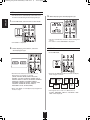
RD-8504
RD-8504(G)_ENG_091217:RD-8504(G) 2009-12-21 오
11:36 페이지 2
Introduction
ENGLISH
READ THIS BEFORE OPERATING YOUR UNIT
This symbol is intended to alert the user to the presence of
uninsulated "dangerous voltage" within the product's
enclosure that may be of sufficient magnitude to constitute
a risk of electric shock to persons.
CAUTION
: TO REDUCE THE RISK OF ELECTRIC
SHOCK, DO NOT REMOVE COVER (OR
BACK). NO USER-SERVICEABLE PARTS
INSIDE. REFER SERVICING TO
QUALIFIED SERVICE PERSONNEL.
This symbol is intended to alert the user to the presence of
important operating and maintenance (servicing)
instructions in the literature accompanying the appliance.
WARNING : TO REDUCE THE RISk OF FIRE OR ELECTRIC SHOCk,
DO NOT ExPOSE THIS APPLIANCE TO RAIN OR mOISTURE.
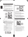
Caution regarding installation
Note : For heat dispersal, do not install this unit in a confined space such as a bookcase or similar enclosure.
Do not block ventilation openings or stack other equipment on the top.
FOR YOUR SAFETY
EUROPE
AUSTRALIA
220 V
240 V
Units shipped to Australia are designed for operation on 240 V AC only.
To ensure safe operation, the three-pin plug supplied must be inserted only into a standard threepin power point which is effectively earthed through the normal household wiring. Extension cords
used with the equipment must be three-core and be correctly wired to provide connection to earth.
Improper extension cords are a major cause of fatalities. The fact that the equipment
operates satisfactorily does not imply that the power point is earthed and that the installation
is completely safe. For your safety, if in any doubt about the effective earthing of the power
point, consult a qualified electrician.
PAN-EUROPEAN UNIFIED VOLTAGE
All units are suitable for use on supplies 220-240 V AC.
CAUTION
Information for Users on Collection and Disposal of
Old Equipment and used Batteries
• Leave a space around the unit for sufficient ventilation.
• Avoid installation in extremely hot or cold locations, or in an area
that is exposed to direct sunlight or heating equipment.
• Keep the unit free from moisture, water, and dust.
• Do not let foreign objects in the unit.
• The ventilation should not be impeded by covering the ventilation
openings with items, such as newspapers, table-cloths, curtains,
etc.
• No naked flame sources, such as lighted candles, should be
placed on the unit.
• Please be care the environmental aspects of battery disposal.
• The unit shall not be exposed to dripping or splashing for use.
• No objects filled with liquids, such as vases, shall be placed on
the unit.
• Do not let insecticides, benzene, and thinner come in contact
with the set.
• Never disassemble or modify the unit in any way.
■Notes on the AC power cord and the wall outlet.
• The unit is not disconnected from the AC power source(mains)
as long as it is connected to the wall outlet, even if the unit has
been turned off.
• To completely disconnect this product from the mains,
disconnect the plug from the wall socket outlet.
• When setting up this product, make sure that the AC outlet you
are using is easily accessible.
• Disconnect the plug from the wall outlet when not using the unit
for long periods of time.
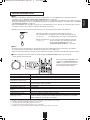
These symbols on the products, packaging, and/or
accompanying documents mean that used electrical and
electronic products and batteries should not be mixed
with general household waste. For proper treatment,
recovery and recycling of old products and used
batteries, please take them to applicable collection
points, in accordance with your national legislation.
By disposing of these products and batteries correctly,
you will help to save valuable resources and prevent any
potential negative effects on human health and the
environment which could otherwise arise from
inappropriate waste handling.
For more information about collection and recycling of
old products and batteries, please contact your local
municipality, your waste disposal service or the point of
sale where you purchased the items.
[Information on Disposal in other Countries outside the
European Union]
These symbols are only valid in the European Union. If
you wish to discard these items, please contact your
local authorities or dealer and ask for the correct method
of disposal.
Note for the battery symbol (bottom two symbol
examples):
The sign Pb below the symbol for batteries indicates that
this batteries contains lead.
2
RD-8504(G)_ENG_091217:RD-8504(G) 2009-12-21 오
11:36 페이지 3
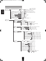
• Introduction
READ THIS BEFORE OPERATING YOUR UNIT . . . . . . . . . . . . . . . . . . . . . . . . . . . . . . . . . . . . . . . . . . . . 2
• System Connections . . . . . . . . . . . . . . . . . . . . . . . . . . . . . . . . . . . . . . . . . . . . . . . . . . . . . . . . . . . . . . . . . . . . 4
• Front Panel Controls . . . . . . . . . . . . . . . . . . . . . . . . . . . . . . . . . . . . . . . . . . . . . . . . . . . . . . . . . . . . . . . . . . . 11
• Universal Remote Controls . . . . . . . . . . . . . . . . . . . . . . . . . . . . . . . . . . . . . . . . . . . . . . . . . . . . . . . . . . . . . . 13
OPERATING COMPONENTS WITH REMOTE CONTROL . . . . . . . . . . . . . . . . . . . . . . . . . . . . . . . . . . . 15
REMOTE CONTROL OPERATION RANGE . . . . . . . . . . . . . . . . . . . . . . . . . . . . . . . . . . . . . . . . . . . . . . . 15
LOADING BATTERIES . . . . . . . . . . . . . . . . . . . . . . . . . . . . . . . . . . . . . . . . . . . . . . . . . . . . . . . . . . . . . . . 15
USING FUNCTIONS OF REMOTE CONTROL . . . . . . . . . . . . . . . . . . . . . . . . . . . . . . . . . . . . . . . . . . . . . 16
• Operations
LISTENING TO A PROGRAM SOURCE . . . . . . . . . . . . . . . . . . . . . . . . . . . . . . . . . . . . . . . . . . . . . . . . . . 19
SURROUND SOUND . . . . . . . . . . . . . . . . . . . . . . . . . . . . . . . . . . . . . . . . . . . . . . . . . . . . . . . . . . . . . . . . 21
ENJOYING SURROUND SOUND . . . . . . . . . . . . . . . . . . . . . . . . . . . . . . . . . . . . . . . . . . . . . . . . . . . . . . . 23
LISTENING TO RADIO BROADCASTS . . . . . . . . . . . . . . . . . . . . . . . . . . . . . . . . . . . . . . . . . . . . . . . . . . 27
LISTENING TO RDS BROADCASTS (FM ONLY) . . . . . . . . . . . . . . . . . . . . . . . . . . . . . . . . . . . . . . . . . . 29
(RDS Tuner (Regional Option for some countries in Europe, etc))
RECORDING . . . . . . . . . . . . . . . . . . . . . . . . . . . . . . . . . . . . . . . . . . . . . . . . . . . . . . . . . . . . . . . . . . . . . . . 31
DIGITAL AUDIO RECORDING WITH MD RECORDER . . . . . . . . . . . . . . . . . . . . . . . . . . . . . . . . . . . . . . 32
OTHER FUNCTIONS . . . . . . . . . . . . . . . . . . . . . . . . . . . . . . . . . . . . . . . . . . . . . . . . . . . . . . . . . . . . . . . . . 33
ROOM 2 SOURCE PLAYBACK . . . . . . . . . . . . . . . . . . . . . . . . . . . . . . . . . . . . . . . . . . . . . . . . . . . . . . . . 34
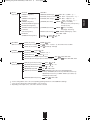
• OSD menu Settings . . . . . . . . . . . . . . . . . . . . . . . . . . . . . . . . . . . . . . . . . . . . . . . . . . . . . . . . . . . . . . . . . . . . 36
SETTING THE SYSTEM SETUP . . . . . . . . . . . . . . . . . . . . . . . . . . . . . . . . . . . . . . . . . . . . . . . . . . . . . . . . 40
SETTING THE SPEAKER / ROOM EQ SETUP . . . . . . . . . . . . . . . . . . . . . . . . . . . . . . . . . . . . . . . . . . . . 43
SETTING THE INPUT SETUP . . . . . . . . . . . . . . . . . . . . . . . . . . . . . . . . . . . . . . . . . . . . . . . . . . . . . . . . . . 51
SETTING THE MULTI ROOM SETUP . . . . . . . . . . . . . . . . . . . . . . . . . . . . . . . . . . . . . . . . . . . . . . . . . . . 56
SETTING THE SOUND PARAMETER . . . . . . . . . . . . . . . . . . . . . . . . . . . . . . . . . . . . . . . . . . . . . . . . . . . 57
SETTING THE ADVANCED VIDEO . . . . . . . . . . . . . . . . . . . . . . . . . . . . . . . . . . . . . . . . . . . . . . . . . . . . . 58
• Troubleshooting Guide . . . . . . . . . . . . . . . . . . . . . . . . . . . . . . . . . . . . . . . . . . . . . . . . . . . . . . . . . . . . . . . . . 59
• Specifications . . . . . . . . . . . . . . . . . . . . . . . . . . . . . . . . . . . . . . . . . . . . . . . . . . . . . . . . . . . . . . . . . . . . . . . . . 60
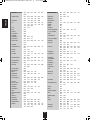
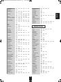
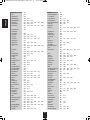
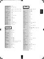
• Setup Code Table . . . . . . . . . . . . . . . . . . . . . . . . . . . . . . . . . . . . . . . . . . . . . . . . . . . . . . . . . . . . . . . . . . . . . . 61
3
ENGLISH
contents
RD-8504(G)_ENG_091217:RD-8504(G) 2009-12-21 오
11:36 페이지 4
ENGLISH
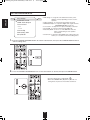
System Connections
• Please be certain that this unit is unplugged from the AC outlet before making any connections.
• Since different components often have different terminal names, carefully read the operating instructions of the component
connected.
• Be sure to observe the color coding when connecting audio, video and speaker cords.
• Make connections firmly and correctly. If not, it can cause loss of sound, noise or damage to the receiver.
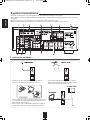
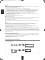
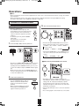
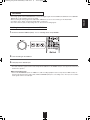
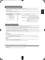
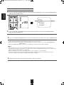
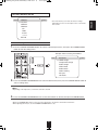
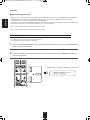
1. CONNECTING ANTENNAS
• A 75Ω outdoor FM antenna may be used to further
improve the reception. Disconnect the indoor antenna
before replacing it with the outdoor one.
• Change the position of the FM indoor antenna until you
get the best reception of your favorite FM stations.
• Place the AM loop antenna as far as possible from the receiver, TV set, speaker cords and the AC input cord and set it to a
direction for the best reception.
• If the reception is poor with the AM loop antenna, an AM outdoor antenna can be used in place of the AM loop antenna.
4
RD-8504(G)_ENG_091217:RD-8504(G) 2009-12-21 오
11:36 페이지 5
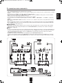
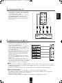
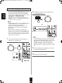
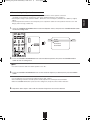
• The jacks of VIDEO 1 may also be connected to a DVD recorder or other digital video recording component. For details, refer
to the operating instructions of the component to be connected.
• The jacks of VIDEO 2/VIDEO 3 can also be connected to an additional video component such as a cable TV tuner or satellite
system.
• Connect the jacks of VIDEO 3 to the video component in the same way.
• There are three types of video jacks (COMPONENT, S-VIDEO, (composite) VIDEO) for analog video connections and the
HDMI connectors for digital video and audio connections.
Connect them to the corresponding video jacks according to their capability.
• For your reference, the excellence in picture quality is as follows : "HDMI” > "COMPONENT" > "S-VIDEO" > "(composite)
VIDEO" .
• When making COMPONENT VIDEO connections, connect "Y" to "Y", "PB/CB" to "CB"(or "B-Y", "PB") and "PR/CR" to "CR"(or
"R-Y", "PR").
• When recording video program sources through VIDEO 1 OUT jack or viewing video program sources through MONITOR
OUT or ROOM 2 OUT jack, you must use the same type of video jacks that you did connect to video playback components
such as DVD player, cable TV tuner, etc.
■Video conversion
• Depending on the Video Mode settings, this unit converts the video input signal (such as component video signal, S-Video
signal and composite video signal) and outputs from the HDMI MONITOR OUT. (For details, refer to “When selecting the
Video Mode” on page 52.)
■Notes :
• You can connect Apple iPod to this receiver via Sherwood iPod dock. If Sherwood iPod dock is connected to DIGI LINK-i jack
for system control, you should connect its video and audio jacks to the "VIDEO 2" jacks of this receiver. Because, when you
control your iPod with the unit's remote control, the VIDEO 2/iPod is automatically selected as an input source and the
corresponding operation is performed.
• The OSD menu and the momentary OSD can be displayed via the HDMI MONITOR OUT only.
However, when the Video Scaling is set to HDMI Bypass and the video signals are input into the HDMI IN, the momentary
OSD cannot be displayed via the HDMI MONITOR OUT. (For details, refer to “When selecting the Video Scaling” on page
53.)
5
ENGLISH
2. CONNECTING VIDEO COmPONENTS
RD-8504(G)_ENG_091217:RD-8504(G) 2009-12-21 오
11:36 페이지 6
Continued
ENGLISH
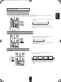
■HDmI (High Definition multimedia Interface) connection : (*1)
• You can connect the source component (BD player, etc.) to the display component (TV, projector, etc.) through this receiver
with using a commercially available HDMI cord.
• The HDMI connection can carry uncompressed digital video signals and digital audio signals.
• The HDMI video stream signals (video signals) are theoretically compatible with DVI-D. When connecting to a TV monitor,
etc., equipped with DVI-D connector, it is possible to connect using a commercially available HDMI-DVI converter cord.
Since the HDMI-to-DVI connection cannot carry any audio signals, you should make audio connections to play the audio
signals on the component equipped with DVI-D connector. (For details, refer to the operating instructions of its.)
• If you connect the HDMI INs to your video components, it is easier to do so following the default settings.
• If your HDMI connection is different from the default setting, you should assign the HDMI INs you used with the "When
selecting the HDMI Assign" procedure on page 52.
• The default settings are as follows :
HDMI 1 : VIDEO 1, HDMI 2 : VIDEO 2/iPod, HDMI 3 : VIDEO 3
■Copyright protection system
• This unit supports HDCP (High-bandwidth Digital Contents Protection), technology to protect copyright of digital video signals
against illegal duplication. HDCP must also be supported on the components connected to this unit.
• This unit is HDMI Ver. 1.3 compatible.
• HDMI, the HDMI logo and High-Definition Multimedia Interface are trademarks or registered trademarks of HDMI licensing
LLC.
■Notes :
• For stable signal transfer, we recommend using HDMI cords that are a maximum of 5 meters in length.
• Among the components that support HDMI, some components can control other components via the HDMI connector.
However, this unit cannot be controlled by another component via the HDMI connector.
• The audio signals from the HDMI connector (including the sampling frequency and bit length) may be limited by the
component that is connected.
• The video signals will not be output properly if a component incompatible with HDCP is connected.
• If the resolutions of the video signals which are output from the MONITOR OUTs and your monitor TV are not matched, the
picture is not clear, natural or displayed. In this case, change the setting of the resolution on the source component (DVD
player, etc.) to one which the monitor TV can handle. (For details, refer to the operating instructions of the source component.)
• When you want to enjoy only the picture on your TV, not the sound, you should set the HDMI Audio Output to Speaker not to
output the digital audio signal from the HDMI MONITOR OUT of this receiver. (For details, refer to "When selecting the HDMI
Audio Output" on page 41.)
■Component video input default settings: (*2)
• If you connect the COMPONENT VIDEO INs to your video components, it is easier to do so following the default settings.
• If your component video connections are different from the default setting, you should assign the COMPONENT VIDEO INs
you used with the "When selecting the Component Assign" procedure on page 52.
• The default settings are as follows:
COMPONENT IN 1 : VIDEO 1, COMPONENT IN 2 : VIDEO 2/iPod
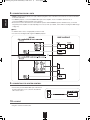
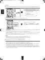
3. CONNECTING AUDIO COmPONENTS
• When recording audio signals, connect the AUDIO IN/OUT jacks of 'VIDEO 1" to audio recording equipment such as a tape
deck, an MD recorder, etc.
6
RD-8504(G)_ENG_091217:RD-8504(G) 2009-12-21 오
11:36 페이지 7
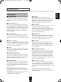
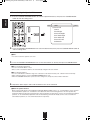
SURROUND SUBWOOFER
FRONT
CENTER
SUR.BACK
• Use these jacks to connect the corresponding outputs
of a DVD player or external decoder, etc. that has 6, 7
or 8 channel analog audio outputs.
• In case of 6 or 7 channel outputs, do not connect both
of the SURROUND BACK L and R inputs or the
SURROUND BACK R input of this unit. (For details,
refer to the operating instructions of the component to
be connected.)
EXTERNAL IN
5. CONNECTING DIGITAL INS AND OUT
• The OPTICAL and the COAXIAL DIGITAL OUTs of the
components that are connected to this unit can be
connected to these DIGITAL INs.
• A digital input should be connected to the components
such as a CD player, DVD player, etc. capable of
outputting DTS Digital Surround, Dolby Digital or PCM
format digital signals, etc.
• If the component with OPTICAL IN jack is connected to
the OPTICAL OUT jack of this unit, you can record the
high quality sound of CDs, etc. without degradation.
• For details, refer to the operating instructions of the
component connected.
• When making the COAXIAL DIGITAL connection, be
sure to use a 75 Ω COAXIAL cord, not a conventional
AUDIO cord.
• All of the commercially available optical fiber cords
cannot be used for the equipment. If there is an optical
fiber cord which cannot be connected to your equipment,
consult your dealer or nearest service organization.
■Notes :
• Be sure to make either a OPTICAL or a COAXIAL DIGITAL connection on each component. (You don’t need to do both.)
• The digital audio signals input into the OPTICAL and the COAXIAL DIGITAL INs (, not the HDMI INs) can be output from
the OPTICAL DIGITAL OUT.
• Depending on the digital audio signal format, some digital signals cannot be output from the OPTICAL OUT jack.
■Digital input default settings
• If you connect the DIGITAL INs to your components, it is easier to do so following the default settings.
• If your DIGITAL connections are different from default settings, you should assign the DIGITAL INs you used with the
"When selecting the Audio Assign" procedure on page 52.
• The default settings are as follows :
OPTICAL IN 1:VIDEO 1, OPTICAL IN 2:VIDEO 2/iPod, COAXIAL IN 1 : CD, COAXIAL IN 2 : F. AUX
7
ENGLISH
4. CONNECTING ExTERNAL INS
RD-8504(G)_ENG_091217:RD-8504(G) 2009-12-21 오
11:36 페이지 8
ENGLISH
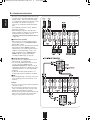
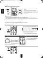
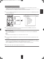
6. CONNECTING SPEAkERS
• Be sure to connect speakers firmly and correctly
according to the channel(left and right) and the
polarity (+ and -). If the connections are faulty,
no sound will be heard from the speakers, and if
the polarity of the speaker connection is
incorrect, the sound will be unnatural and lack
bass.
• For installing the speakers, refer to "Speaker
placement" on page 9.
• After installing the speakers, first adjust the
speaker settings according to your environment
and speaker layout. (For details, refer to
"SETTING THE SPEAKER /ROOM EQ SETUP"
on page 43.)
■Surround back speakers
• When using only one surround back speaker,
you should connect it to SURROUND BACK/
MULTI LEFT channel.
• Because this receiver cannot drive the surround
back speakers and the ROOM 2 speakers
simultaneously, you should assign their power
amplifier correctly depending on how to use
them. (For details, refer to "CONNECTING
ROOM 2 OUTS" on page 10 and "When
selecting the AMP Assign" on page 41.)
■Front Bi-Amp Connections.
• Some speakers are equipped with two sets of
input terminals, for bi-amplification.
• If no other surround back speakers are used,
you can connect the FRONT and the
SURROUND BACK/MULTI channels to the biamp-capable speakers. (For details, refer to the
operating instructions of your bi-amp-capable
speakers.)
• To drive the bi-amp-capable speakers, you
should assign the power amplifier to "Bi AMP".
■Note :
• Before making bi-amp connections, remove the
short-circuiting bars from the terminals of your
speakers.
Caution :
• Be sure to use the speakers with the impedance
of 6 ohms or above.
• Do not let the bare speaker wires touch each
other or any metal part of this unit. This could
damage this unit and/or the speakers.
• Never touch the speaker terminals while the AC
input cord is connected to the wall AC outlet.
Doing so could result in electric shocks.
8
RD-8504(G)_ENG_091217:RD-8504(G) 2009-12-21 오
11:36 페이지 9
Continued
■Connecting speaker wire
2. Lossen by turning the
speaker terminal counterclockwise.
3. Insert the bare part of the
wire.
4. Tighten by turning it
clockwise.
ENGLISH
1. Strip away approx. 10 mm
(3/8 inch) of wire insulation,
then twist the wire ends
tight.
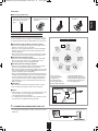
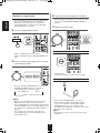
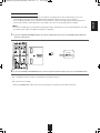
Speaker placement
Ideal speaker placement varies depending on the size of
your room and the wall coverings, etc. The typical example
of speaker placement and recommendations are as follows :
■Front left and right speakers and center speaker
• Place the front speakers with their front surfaces as flush
with TV or monitor screen as possible.
• Place the center speaker between the front left and right
speakers and no further from the listening position than
the front speakers.
• Place each speaker so that sound is aimed at the location
of the listener’s ears when at the main listening position.
■Surround left and right speakers
• Place the surround speakers approximately 1 meter (40
inches) above the ear level of a seated listener on the
direct left and right of them or slightly behind.
■Surround back left and right speakers
• Place the surround back speakers at the back facing the
front at a narrower distance than front speakers.
• When using a single surround back speaker, place it at the
rear center facing the front at a slightly higher position (0
to 20 cm ) than the surround speakers.
• We recommend installing the surround back speaker(s) at
a slightly downward facing angle. This effectively prevents
the surround back channel signals from reflecting off the
TV or screen at the front center, resulting in interference
and making the sense of movement from the front to the
back less sharp.
■Subwoofer
• The subwoofer reproduces powerful deep bass sounds.
Place a subwoofer anywhere in the front as desired.
1. TV or Screen
2. Front left speaker
3. Subwoofer
4. Center speaker
5. Front right speaker
6. Surround left speaker
■Notes :
• When using a conventional TV, to avoid interference with
the TV picture, use only magnetically shielded front
left and right and center speakers.
• To obtain the best surround effects, the speakers except
the subwoofer should be full range speakers.
7.
CONNECTING SUBWOOFER PRE OUT
• To emphasize the deep bass sounds, connect a powered
subwoofer.
9
7. Surround right speaker
8. Surround back left speaker
9. Surround back right speaker
10. Surround center speaker
11. Listening position
RD-8504(G)_ENG_091217:RD-8504(G) 2009-12-21 오
11:36 페이지 10
ENGLISH
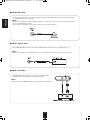
8. CONNECTING ROOm 2 OUTS
• ROOM 2 playback feature allows you to play a different program source in another room as well as one source in the main
room at the same time.
• For ROOM 2 playback, connect the ROOM 2 OUT jacks to the amplifier, TV, etc. installed in another room, or
connect the ROOM 2 speaker terminals to the speakers.
• Because this receiver cannot drive the surround back speakers and the ROOM 2 speakers simultaneously, you should
assign their power amplifier correctly depending on how to use them. (For details, refer to "When selecting the AMP Assign"
on page 41.)
■Notes :
• To minimize hum or noise, use high quality connection cords.
• You cannot use the digital audio signal for ROOM 2 playback.
9. CONNECTING FOR SYSTEm CONTROL
• Connect this jack to the DIGI LINK-i jack of Sherwood
iPod dock that allows you to control the iPod with the
unit's remote control.
10. AC INPUT
• Plug this cord into a wall AC outlet.
10
RD-8504(G)_ENG_091217:RD-8504(G) 2009-12-21 오
11:36 페이지 11
ENGLISH
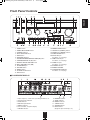
Front Panel Controls
1. POWER switch
2. POWER ON/STANDBY button
3. STANDBY indicator
4. INPUT SELECTOR knob
5. BAND button
6. EXTERNAL IN button
7. SURROUND MODE/CONTROL DOWN(▼) button
8. STEREO/CONTROL UP(▲) button
9. MASTER VOLUME CONTROL knob
10. MULTI CONTROL knob(◀/▶)
11. HEADPHONE jack
12. SPEAKER button
13. ROOM 2 button
14. CHANNEL LEVEL button
15. SETUP button
16. MEMORY/ENTER button
17. TUNING UP(+)/DOWN(-) buttons
18. PRESET UP(+)/DOWN(-) buttons
19. AUDIO ASSIGN button
20. SETUP MIC jack
For details, see next page.
21. FRONT AUX IN jack
For details, see next page.
22. VIDEO 4 IN jacks
For details, see next page.
23. SPEAKER indicator
24. REMOTE SENSOR
25. FLUORESCENT DISPLAY
For details, see next page.
■FLUORESCENT DISPLAY
1. Input, frequency, volume level, operating information, etc.
2. Surround mode indicators
3. AUTO indicator
4. DIGITAL input indicator
5. DIRECT indicator
6. Preset number, sleep time display
7. PRESET indicator
11
8. MEMORY indicator
9. SLEEP indicator
10. ROOM 2 indicator
11. TUNED indicator
12. STEREO indicator
13. RDS indicators
(Regional option for Europe, etc.)
RD-8504(G)_ENG_091217:RD-8504(G) 2009-12-21 오
11:36 페이지 12
ENGLISH
■ SETUP mIC JACk
• To use Auto Setup function, connect the supplied microphone to the SETUP MIC jack.(For details, refer to "When
selecting the Auto Setup" on page 43.)
■Notes:
• Because the microphone for Auto Setup is designed for use with this receiver, do not use a microphone other than
the one supplied with this receiver.
• After you have completed the auto setup procedure, disconnect the microphone.
■ FRONT AUx IN JACk
• The FRONT AUX IN jack can be connected to additional audio components such as an MP3 player, etc.
■ Note :
• When connecting this jack to an MP3 player, etc., you should use the stereo mini cord, not a mono mini cord.
■VIDEO 4 IN JACkS
• The VIDEO 4 IN jacks may be also connected to an additional video
component such as a camcorder, a video game player, etc.
■ Note:
• When not using the VIDEO 4 IN jacks, cover them with the supplied cap.
12
RD-8504(G)_ENG_091217:RD-8504(G) 2009-12-21 오
11:36 페이지 13
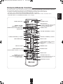
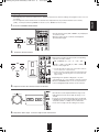
This universal remote control can operate not only this receiver but also most popular brands of audio and video components
such as iPod docks, CD players, tape decks, TVs, BD/DVD players, satellite receivers, cable boxes, etc.
• To operate 7 components other than this receiver, you should enter the setup code for each component.
(For details, refer to “USING FUNCTIONS OF REMOTE CONTROL” on page 16.)
• The numbered buttons on the remote control have different functions in different device modes. For details, refer to
"FUNCTION TABLE of the NUMBERED BUTTONS" on the next page.
LED
2 STANDBY button
POWER ON button 1
DEVICE buttons
To operate the desired component with
this remote control, first select the
corresponding DEVICE button.
ROOM2 VOLUME
UP/DOWN (∧/∨) buttons
ROOM2 INPUT SELECTOR button
MUTE button 4
3 ROOM 2 button
5
6 VOLUME UP/DOWN(+/-) buttons
9
8
7
11
10
TUNING UP/DOWN(+/-) buttons 12
13 PRESET UP/DOWN(+/-) buttons
TEST TONE button 14
15 SETUP button
CURSOR CONTROL, ENTER </SEARCH
16 MODE, SELECT〈 , 〉 > buttons
The function in "< >" are regional option for
Europe, etc.
DISPLAY button 17
18 DIMMER button
AUDIO ASSIGN button 19
21 STEREO button
SURROUND MODE UP/DOWN (〉/〈) buttons 20
23
22
25 SLEEP button
NUMERIC (0~9, +10)/
INPUT SELECTOR buttons 24
To select the desired input source
of TUNER~VIDEO 4
MACRO(M1~M3) buttons
To operate a macro function, press the
corresponding MACRO button.
EXTERNAL IN button
13
ENGLISH
Universal Remote Controls
RD-8504(G)_ENG_091217:RD-8504(G) 2009-12-21 오
11:36 페이지 14
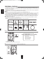
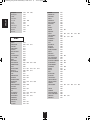
■FUNCTION TABLE of the NUMBERED BUTTONS.
ENGLISH
(for iPod Dock)
(for CD player) (for Tape deck)
(for VCR)
(for BD/DVD
player)
(for TV)
(for Satellite
receiver)
(for Cable box)
POWER
ON
POWER
ON
POWER
ON
POWER
ON
POWER
ON
POWER
ON
STANDBY
(POWER OFF)
STANDBY
(POWER OFF)
STANDBY
(POWER OFF)
STANDBY
STANDBY
STANDBY
(POWER OFF) (POWER OFF) (POWER OFF)
RANDOM
ALBUM
UP/DOWN
(∧/∨)
MUTE
MUTE
MUTE
MUTE
CHANNEL
UP/DOWN
(∧/∨)
CHANNEL
UP/DOWN
(∧/∨)
CHANNEL
UP/DOWN
(∧/∨)
CHANNEL
UP/DOWN
(∧/∨)
VOLUME
VOLUME
VOLUME
UP/DOWN (+/-) UP/DOWN (+/-) UP/DOWN (+/-)
VOLUME
UP/DOWN (+/-)
INPUT
SELECTOR
INPUT
SELECTOR
RECORD
PLAY/PAUSE
PAUSE
PAUSE
PAUSE
PLAY
PLAY
PLAY
PLAY
STOP
STOP
STOP
REWIND /FAST
FORWARD (
/
)
REVERSE /FORWARD
SKIP (
/
)
REVERSE /FORWARD
SKIP (
/
)
INPUT
SELECTOR
INPUT
SELECTOR
NUMERIC
NUMERIC
NUMERIC
RECORD
PAUSE
REWIND /FAST
FORWARD (
/
INPUT
SELECTOR
STOP
)
REVERSE /FORWARD
SEARCH (
/
)
REVERSE /FORWARD
SKIP (
/
)
MENU
DISC MENU
HOME MENU
CURSOR
UP/DOWN
CURSOR
UP/DOWN
ENTER
ENTER
DISPLAY
RETURN
REPEAT
REPEAT
PLAY LIST
PLAY LIST
UP/DOWN(>/<)
UP/DOWN(>/<)
PLAY MODE
AUDIO
SUBTITLE
NUMERIC
NUMERIC
NUMERIC
DOCK MODE
■Notes :
• Some functions for each component may not be available or may work differently.
• Depending on other kinds of components that are available for each DEVICE button, some functions may not be available or
may work differently, too.
• For details about functions, refer to the operating instructions of each component.
14
11:36 페이지 15
oPeRAtInG coMPonents WItH ReMote contRoL
1. Enter the setup code for each
ReMote contRoL oPeRAtIon RAnGe
• Use the remote control within a range of about 7 meters
(23 feet) and angles of up to 30 degrees aiming at the
remote sensor.
component other
than this receiver. For details, refer to "Entering
a setup code" on page 16.
2. Turn on the component you want to operate.
3. Press the DEVICE button on the
remote control
corresponding to the component you wish to
operate.
4. Aim the remote control at the REMOTE
SENSOR of the component you wish to control
and press the button corresponding to the
operation you want.
• In such a case that some components do not have the
REMOTE SENSOR which receives the remote signals,
this remote control cannot operate them.
LoADInG BAtteRIes
• When the remote control does not operate, the old batteries should be replaced. In this case, load new batteries within several
minutes after removing old batteries.
• If the batteries are removed or have been exhausted for a longer period of time, memorized contents will be cleared. Should
this happen, you should memorize them again.
1. Remove the cover.
2. Load two batteries ("AAA" size, 1.5V) matching
the polarity.
• Remove the batteries when they are not used for a long
time.
• Do not use the rechargeable batteries (Ni-Cd type).
• Be sure to use alkaline batteries.
15
ENGLISH
RD-8504(G)_ENG_091217:RD-8504(G) 2009-12-21 오
RD-8504(G)_ENG_091217:RD-8504(G) 2009-12-21 오
11:36 페이지 16
ENGLISH
UsInG FUnctIons oF ReMote contRoL
• This remote control can control up to 8 different components.
• Before operating audio and video components other than this receiver with using this remote control, the setup code for each
component should be entered.
• For system remote control operation, “000” was stored previously in the memory of the device button “DOCK” for Sherwood iPod
dock, “CD” for Sherwood CD player, “BD” for Sherwood BD/DVD player and “TV” for Sherwood TV respectively as its factory
setup code. So, you don’t need to enter its code for each Sherwood component except in such a case that its code does not work.
Entering a setup code
1. Turn on the component you want to operate.
4. Enter a 3 digit code, aiming the remote control at
the remote sensor on the component.
Example: When entering “001”.
2. Find the setup codes according to the type and
the brand name of your component, referring to
“Setup Code Table” on page 61.
3. Press and hold down both the ENTER button
and the desired one of the DEVICE buttons for
more than 1 seconds.
• If entering is performed successfully, the LED will flicker
twice.
• To be sure that the setup code is correct, press the
POWER ON (or STANDBY) button. If your component
is turned off, the setup code is correct.
• When your component is not turned off, repeat the
above steps 2 to 4, trying each code for your
component until you find one that works.
■Notes:
• If the LED did not flicker twice, then repeat the above
steps 3 to 4 and try entering the same code again.
• Manufacturers may use different setup codes for the
same product category. For that reason, it is important
that you check to see if the code you have entered
operates as many controls as possible. If only a few
functions operate, check to see if another code will work
with more buttons.
• The LED will flicker once.
5. Repeat the above steps 1 to 4 for each of your
■Note :
components.
• The “AVR” button is unavailable for the audio
components other than this receiver.
16
RD-8504(G)_ENG_091217:RD-8504(G) 2009-12-21 오
11:36 페이지 17
■Removing a punch-through function
• When removing the AUDIO volume punch-through, press
and hold down both “AVR” button and “VOLUME -” button
for more than 1 second.
This remote control may be programmed to operate either
the AUDIO volume punch-through or the TV volume and/or
TV channel punch-through in conjunction with any of the 8
components controlled by this remote control.
For example, since this receiver will likely be used as the
sound system while watching TV, you may want to adjust
this receiver’s volume although this remote control is set to
control the TV.
• When programming this remote control for the AUDIO
volume punch-through, press and hold down both “AVR”
button and “VOLUME +” button for more than 1 second.
• If removing is performed successfully, the LED will flicker
twice.
• When you want to remove either TV volume or TV
channel punch-through, press and hold down both “TV”
button and either “VOLUME -” or “CH ∨” button for more
than 1 second.
• If programming is performed successfully, the SET LED
will flicker twice.
• When you want either TV volume or TV channel
punch-through, press and hold down both “TV” button
and either “VOLUME +” or “CH ∧” button for more
than 1 second.
■Removing all punch-through functions
Press and hold down both “AVR” button and “AUDIO
ASSIGN” button for more than 1 second.
■Note :
• If you use one of AUDIO and TV volume punchthrough functions, you cannot use the other.
• If removing all punch-through functions is performed
successfully, the LED will flicker twice.
17
ENGLISH
Using a punch-through function
RD-8504(G)_ENG_091217:RD-8504(G) 2009-12-21 오
11:36 페이지 18
ENGLISH
Programming a macro function
3. Press “ENTER” button.
• The macro function enables you to program a
series of button operations(up to 10) on this
remote control into a single button.
• You can store up to three separate macro
command sequences into “M1”, “M2” and “M3”
buttons.
1. Press and hold down both “ENTER” button and
one of three NUMERIC buttons (“1” ~ “3”)
corresponding to “M1”~”M3” buttons for more
than 1 second.
Example: When programming a series of button
operations into “M1” button.
• If the programming is performed successfully, the
LED will flicker twice.
■To remove a macro program
• When removing a macro program, perform the
above steps 1 and 3, but ignore the step 2.
■To change a macro program
• When a new macro program is stored into a
MACRO button with performing the above steps
1 to 3, the previous macro program is cleared
from the memory of the MACRO button.
Operating a macro function
• If the macro mode is entered, the LED will flicker
once.
• Aim the remote control at the REMOTE SENSORs of
the components to be controlled and press the MACRO
button you want.
Example: When pressing “M1” button.
2. Press the operation buttons you want to
program in order.
■Note :
You should press the corresponding DEVICE
buttons before pressing each operation button.
Example: When playing a BD on the BD player
connected to VIDEO 2 jacks of this
receiver.
①. Press “AVR” button to control this receiver.
②. Press “POWER ON” button to turn this
receiver on.
③. Press “AVR” button to control this receiver.
④. Press “VIDEO 2(7)” button to select the
desired input source.
⑤. Press “BD” button to control the BD player.
⑥. Press “POWER ON” button to turn the BD
player on.
⑦. Press “BD” button to control the BD player.
⑧. Press “▶” button to start playback.
■Notes:
• The codes programmed into a MACRO button will be
transmitted at an interval of 0.5 seconds. However,
some components may not be able to complete one
operation in 0.5 seconds and may miss the next code.
In this case, the macro function cannot control the
corresponding components correctly.
• Be sure to use the remote control within the remote
control operation range of the components.
• Depending on the operation status of the components,
etc., the macro function cannot control the
corresponding components correctly.
18
RD-8504(G)_ENG_091217:RD-8504(G) 2009-12-21 오
11:36 페이지 19
■Notes:
• Before operating this receiver with the supplied remote control, refer to "Universal Remote Controls" on page 13 for details
about operation.
• Before operating this receiver, first set this unit as desired for optimum performance, doing the OSD menu setting
procedures. (For details, refer to "OSD Menu Settings" on page 36.)
LISTENING TO A PROGRAm SOURCE
3. Select the desired input source.
Before operation
• Enter the standby mode.
• The STANDBY indicator lights up. This
means that the receiver is not disconnected
from the AC mains and a small amount of
current is retained to support the operation
readiness.
• To switch the power off, push the POWER
switch again.
Then the power is cut off and the
STANDBY indicator goes off.
• Each time the INPUT SELECTOR knob on the front
panel is rotated, the input source changes as follows:
→TUNER ↔ CD ↔ TAPE ↔ F.AUX ↔ VIDEO 1 ←
1. In the standby mode, turn the power on.
(Frequency display)
→ VIDEO 4 ↔ VIDEO 3 ↔ V2/IPOD ←
• Each time the BAND button (or the TUNER button on
the remote control) is pressed, the band changes as
follows:
→ FM ST → FM MONO → AM
■When selecting the ExTERNAL IN as desired,
• Each time the POWER ON/STANDBY button on the front
panel is pressed, the receiver is turned on to enter the
operating mode (the STANDBY indicator goes off) or off
to enter the standby mode(the STANDBY indicator lights
up).
• On the remote control, press the POWER ON button to
enter the operating mode or press the STANDBY button
to enter the standby mode.
2. Switch the speakers on.
• Depending on the power amplifier setting for the
surround back channels and the surround back speaker
setting, "EXT. IN" is displayed and 8(/7/6) separate
analog signals from the component connected to this
input pass through the volume circuits only and can be
heard from your speakers.
• Select the desired input source to cancel the external in
function.
• These analog signals can be heard only, not recorded.
• Then the SPEAKER indicator lights up
and the sound can be heard from the
speakers connected to the speaker
terminals.
• When using the headphones for private
listening, press the SPEAKER button
again to switch the speakers off.
19
ENGLISH
Operations
RD-8504(G)_ENG_091217:RD-8504(G) 2009-12-21 오
11:36 페이지 20
ENGLISH
When CD, F.AUx, VIDEO 1~ 4, ExT.IN is
selected as an input source
6. Operate the selected component for playback.
• When playing back the program sources with surround
sound, refer to "ENJOYING SURROUND SOUND" on
page 23.
• If the Audio Mode is set to the mode other than "Digital"
for the corresponding input source on the INPUT
SETUP menu, you cannot hear the sound from the
selected digital input. (For details, refer to "SETTING
THE INPUT SETUP" on page 51.)
7. Adjust the (overall) volume.
4. Press the AUDIO ASSIGN button.
muting the sound
• "AUD ~ " is displayed for several seconds.
• "AUD ~ " disappears, press the AUDIO ASSIGN button
again.
5. Select the desired of the digital inputs connected
while displaying "AUD ~ ".
• "MUTE" flickers.
• To resume the previous sound level, press it again.
Listening with headphones
• Each time the MULTI CONTROL knob is rotated or the
CURSOR LEFT/RIGHT buttons are pressed, the
corresponding input is selected as follows :
→
OPT 1(Optical 1)
↔
OPT 2 ←
→
---
↔ COX 2 ↔ COX 1(Coaxial 1) ←
(No assignment)
■Notes:
• When the selected digital input is not connected, the
digital input flickers and no sound will be heard.
• The selected digital input is automatically assigned to the
corresponding input source on the INPUT SETUP menu.
(For details, refer to "SETTING THE INPUT SETUP" on
page 51.)
• The sound from the component connected to the
selected digital input can be heard regardless of the
selected input source.
• Ensure that the SPEAKER button is set to off.
• When listening to a DTS or Dolby Digital program
source, if the headphones are plugged in and the
SPEAKER button is set to off, it enters the 2CH
downmix mode automatically. (For details, refer to "2CH
downmix mode" on page 24.)
■Note:
• Be careful not to set the volume too high when using
headphones.
20
RD-8504(G)_ENG_091217:RD-8504(G) 2009-12-21 오
11:36 페이지 21
sURRoUnD soUnD
Surround modes
■DTS Digital Surround
■Dolby Digital
DTS Digital Surround(also called simply DTS) supports up to
5.1 discrete channels and uses less compression for high
fidelity reproduction. Use it with DVDs and CDs bearing the
DTS logo.
Dolby Digital is the multi-channel digital signal format
developed by Dolby Laboratories. Discs bearing the Dolby
Digital logo includes the recording of up to 5.1 channels of
digital signals. This will put you right in the middle of the
action, just like being in a movie theater or concert hall.
■DTS-ES™ Discrete 6.1
This is a 6.1 channel discrete digital audio format adding a
surround back channel to the DTS digital surround sound. The
seven totally separate audio channels provide better spatial
imaging and 360 degrees sound localization, perfect for sounds
that pan across the surround channels. Use it with DVDs
bearing the DTS-ES logo, especially those with a DTS-ES
Discrete sound track.
■Dolby Digital Ex
■DTS - ES™ Matrix 6.1
■Dolby Digital Plus
This is a 6.1 channel discrete digital audio format inserting a
surround back channel to the DTS digital surround sound
through matrix encoding. Use it with DVDs bearing the DTS-ES
logo.
Developed for use with HDTV, including the new video disc
formats Blu-ray and HD DVD, this is the latest multichannel
audio format from Dolby. It supports up to 7.1 channels with
48 kHz/24-bit sampling rate and signal resolution.
■DTS Neo : 6™ surround
■Dolby TrueHD
DTS Neo : 6 is a matrix decoding technology for achieving 7.1
channel surround playback with 2 channel sources. It includes
"DTS Neo : 6 Cinema" suited for playing movies and "DTS
Neo : 6 Music" suited for playing music.
Designed to take full advantage of the additional storage
space offered by the new Blu-ray and HD DVD disc formats,
this new Dolby format offers up to 7.1 discrete channels of
lossless audio performance with 96 kHz/24 bit sampling rate
and signal resolution.
This mode expands 5.1-channel sources for 6.1/7.1 channel
playback. It's especially suited to Dolby Digital EX
soundtracks that include a matrix-encoded surround back
channel. The additional channel adds an extra dimension and
provides an enveloping surround sound experience, perfect
for rotating and fly-by sound effects.
■DTS 96/24
This is high resolution DTS with a 96 kHz sampling rate and
24 bit resolution, providing superior fidelity. Use it with DVDs
bearing the DTS 96/24 logo.
■Dolby Pro Logic IIx surround
This mode expands any 2-channel source for 7.1-channel
playback. It provides a very natural and seamless surround
sound experience that fully envelopes the listener. As well as
music and movies,video games can also benefit from the
dramatic spatial effects and vivid imaging. It includes "Dolby
Pro Logic IIx Movie" suited for playing movies, "Dolby Pro
Logic IIx Music" suited for playing music and "Dolby Pro Logic
IIx Game" suited for playing games.
■DTS-HD High Resolution Audio
Developed for use with HDTV, including the new video disc
formats Blu-ray and HD DVD, this is the latest multi-channel
audio format from DTS. It supports up to 7.1 channels with
96 kHz/24 bit sampling rate and signal resolution.
■DTS-HD master Audio
■Dolby Pro Logic II surround
Designed to take full advantage of the additional storage
space offered by the new Blu-ray and HD DVD disc formats,
this new DTS format offers up to 7.1 discrete channels of
uncompressed digital audio with 96 kHz/24 bit sampling rate
and signal resolution.
If you are not using any surround back speakers, Dolby Pro
Logic II surround will be used instead of Dolby Pro Logic IIx
surround. It incudes Dolby Pro Logic II Movie, Dolby Pro Logic
II Music and Dolby Pro Logic II Game like Dolby Pro Logic IIx
surround.
Manufactured under license under U.S. Patent #'s: 5,451,942;
5,956,674; 5,974,380; 5,978,762; 6,226,616; 6,487,535; 7,212,872;
7,333,929; 7,392,195; 7,272,567 & other U.S. and worldwide patents
issued & pending.
DTS is a registered trademark and the DTS logos, Symbol, DTS-HD
and DTS-HD Master Audio are trademarks of DTS, Inc.
ⓒ 1996-2008 DTS, Inc. All Rights Reserved.
Manufactured under license from Dolby Laboratories.
Dolby and the double-D symbol are registered trademarks
of Dolby Laboratories.
21
ENGLISH
• This receiver incorporates a sophisticated Digital Signal Processor that allows you to create optimum sound quality and sound
atmosphere in your personal Home Theater.
ENGLISH
RD-8504(G)_ENG_091217:RD-8504(G) 2009-12-21 오
11:36 페이지 22
■Room
This mode provides the sound field of a house with a low
ceiling and hard walls for jazz music.
• The following modes apply conventional 2-channel signals
such as digital PCM or analog stereo signals to high
performance Digital Signal Processor to recreate sound
fields artificially. Select one of the 7 provided surround
modes according to the program source you want to play.
■Panorama
This mode provides a dynamic and broad sound space to
heighten the overall impact of the sound track.
■Theater
This mode provides the effect of being in a movie theater
when watching a play.
■Classic
This mode provides the acoustic effects of a large concert
hall for classical music.
■Hall
This mode provides the ambience of a concert hall for
classical music sources such as orchestral, chamber music
or an instrumental solo.
■multi CH Stereo
This mode is designed for playing background music. The
front, surround and surround back channels create a stereo
image that encompasses the entire area.
■Stadium
This mode provides the expansive sound field to achieve the
true stadium effect when watching baseball or soccer games.
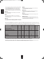
• When using the EXTERNAL INs to play back the sound from the additional multi-channel decoder for surround sound, you can
enjoy the corresponding surround sound, too. (For details, refer to the operating instructions of the component to be connected.)
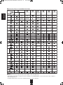
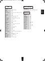
For your reference, the sound from each channel can be reproduced according to the surround modes as follows:
Modes
FRONT L/R
CENTER
SURROUND L/R
DTS-HD HIGH RESOLUTION AUDIO/MASTER AUDIO
Channels
O
O
O
SURROUND BACK L/R
O/—
SUBWOOFER
O
DTS, DTS 96/24
O
O
O
—
O
DTS ES DISCRETE/MATRIX
O
O
O
O
O
DTS NEO: 6 CINEMA/MUSIC
O
O
O
O
—(*)
DOLBY DIGITAL PLUS / DOLBY TRUEHD
O
O
O
O/—
O
DOLBY DIGITAL
O
O
O
—
O
DOLBY DIGITAL EX
O
O
O
O
O
DOLBY PRO LOGIC IIx MOVIE/MUSIC/GAME
O
O
O
O
O
DOLBY PRO LOGIC II MOVIE/MUSIC/GAME
O
O
O
—
O
MULTI PCM
O
O
O
O/—
O
Other Surrounds
O
O
O
O
—(*)
STEREO
O
—
—
—
—(*)
EXTERNAL IN
O
O
O
O
O
(*): Depending on the subwoofer setting, the sound from the subwoofer channel may be reproduced.
• Depending on the speaker settings and the number of the encoded channels, etc., the sound from the corresponding channels
cannot be reproduced.(For details, refer to "SETTING THE SPEAKER / ROOM EQ SETUP" on page 43.)
22
RD-8504(G)_ENG_091217:RD-8504(G) 2009-12-21 오
11:36 페이지 23
■Notes:
• Before surround playback, first perform the speaker setup procedure, etc. on the OSD menu for optimum performance.
(For details, refer to "SETTING THE SPEAKER / ROOM EQ SETUP" on page 43.)
• When playing digital signals from the Dolby Digital program source or selecting the surround mode such as Dolby Pro Logic II
/Dolby Pro Logic IIx Music mode, you can adjust their parameters for optimum surround effect. (For details, refer to "SETTING
THE SOUND PARAMETER" on page 57.)
• When the EXTERNAL IN is selected as an input source, if the Audio Mode is set to “Analog”, the surround modes cannot be
selected. (For details, refer to “When selecting the Audio Mode” on page 53.)
Depending on how to select a surround mode, select the auto surround mode or the manual surround mode.
• Each time this button is pressed, the mode changes as follows :
Auto surround mode : The optimum surround mode will be automatically
("AUTO" lights up.)
selected depending on the signal format being input.
Manual surround mode : You can select the desired of different surround
modes selectable for the signal being input with
("AUTO" goes off.)
using the MULTI CONTROL knob or the
SURROUND MODE UP/DOWN ( 〉 /〈) buttons.
■Notes :
• Even when the auto surround mode is selected and the same type of digital signal format is being input, the optimum
surround mode may vary depending on whether the speaker type is set to "NO" or not.
• When the auto surround mode is selected, the surround modes other than the optimum surround mode cannot be selected.
■When selecting the manual surround mode with pressing the SURROUND MODE button on the front panel.
Select the desired surround mode.
• Each time the MULTI CONTROL knob is
rotated or the SURROUND MODE UP /
DOWN (〉 /〈) buttons are pressed, the
surround mode changes depending on
the input signal format as follows :
Signal format being input
Dolby Digital Plus sources
Dolby TrueHD sources
Dolby Digital EX 6.1 channel sources,
Dolby Digital 5.1 channel sources
Dolby Digital 2 channel sources
DTS-HD High Resolution Audio sources
DTS-HD Master Audio sources
DTS ES Discrete/Matrix 6.1 channel
sources
DTS sources, DTS 96/24 sources
PCM (multi-channel) sources*
PCM (2 channel) sources,
Analog stereo sources
Selectable surround mode
DOLBY DIGITAL +
DOLBY TRUEHD
<DOLBY DIGITAL EX, DOLBY D + PLIIx MUSIC>, (DOLBY D + PLIIx MOVIE), DOLBY DIGITAL
<DOLBY PLIIx MOVIE, DOLBY PLIIx MUSIC, DOLBY PLIIx GAME>, [DOLBY PLII MOVIE,
DOLBY PLII MUSIC, DOLBY PLII GAME]
DTS-HD HI RES
DTS-HD MSTR
<corresponding DTS ES mode, DTS + PLIIx MUSIC>, (DTS + PLIIx MOVIE), DTS
corresponding DTS mode, <DTS + NEO:6, DTS + PLIIx MUSIC>, (DTS + PLIIx MOVIE)
MULTI PCM, <DOLBY PLIIx MOVIE, DOLBY PLIIx MUSIC>
<DOLBY PLIIx MOVIE, DOLBY PLIIx MUSIC, DOLBY PLIIx GAME>, [DOLBY PLII MOVIE, DOLBY
PLII MUSIC, DOLBY PLII GAME], NEO:6 CINEMA, NEO:6 MUSIC, THEATER, HALL, STADIUM,
ROOM, PANORAMA, CLASSIC, MULTI-CH STEREO
• Depending on surround back speaker setting, some surround modes can be selected or not as follows:
< >: Possible only when surround back speaker is not set to "No".
[ ] : Possible only when surround back speaker is set to "No".
( ): Possible only when surround back speaker is set to " 2 Channel".
* : Depending on the signal format being input, the Dolby Pro Logic IIx modes may not be selected.
23
ENGLISH
ENJOYING SURROUND SOUND
RD-8504(G)_ENG_091217:RD-8504(G) 2009-12-21 오
11:36 페이지 24
Continued
■To cancel the surround mode for stereo operation
ENGLISH
• Depending on the signal format which is being input,
either the stereo mode or the 2CH downmix mode is
selected.
• To cancel either the stereo mode or the 2CH
downmix mode, select the surround mode with using
the MULTI CONTROL knob on the front panel or the
SURROUND MODE UP/DOWN (〉 /〈) buttons on the
remote control.
■2CH downmix mode
• This mode allows the multi-channel signals encoded in DTS or Dolby Digital format, etc. to be mixed down into 2 front
channels and to be reproduced through only two front speakers or through headphones.
• When the SPEAKER button is set to off to listen with headphones while playing the multi-channel digital signals from DTS or
Dolby Digital sources, etc., it will enter the 2CH downmix mode automatically.
Adjusting each channel level with test tone
• The volume level of each channel can be adjusted easily with the test tone function.
■Note : When the SPEAKER button is set to off, the test tone function does not work.
1. Enter the test tone mode.
• The test tone mode is displayed and will be heard from the
speaker of each channel for 2 seconds as follows:
→ FL → C → FR → SR
Front Left
SUB
Subwoofer
Center
Front Right
← SL ( ←
Surround Left
SB )
Surround Right
or ( SBL ← SBR) ←
Surround Back Surr.Back Left Surr.Back Right
• When the speaker setting is "No", the test tone of the
corresponding channel is not available.
• ( ) : Possible depending on whether the surround back
channel is set to "2 Channel" or "1 Channel (Left)".
2. At each channel, adjust the level as desired until the sound level of each speaker is heard to be equally loud.
• You can select the desired channel with
pressing the CONTROL UP/DOWN buttons
or the CURSOR UP/DOWN buttons.
3. Cancel the test tone function.
24
RD-8504(G)_ENG_091217:RD-8504(G) 2009-12-21 오
11:36 페이지 25
• After adjusting each channel level with test tone, adjust the channel levels either according to the program sources or to suit
your tastes.
• You can adjust the current channel levels as desired. These adjusted levels are just memorized into user’s memory
("CAL"), not into preset memory("MOVIE" for movieo source, "MUSIC" for music source).
1. Press the CHANNEL LEVEL button.
• Then the memory mode ("CAL", "MOVIE", etc) is displayed
for several seconds.
• When the memory mode or channel level disappears,
press this button again.
2.
Select the desired channel.
• Each time these buttons are pressed, the corresponding
channel is selected as follows:
→ CAL (or MOVIE, etc.) ↔ FL ← C ← FR ← SR ←
→ <LFE> ↔ SUB ↔ SL(↔SB) or (↔SBL ↔ SBR) ←
DTS LFE or Dolby Digital LFE
( ): Possible depending on whether the surround back channel is
set to "2 Channel" or "1 Channel (Left)".
< >: Possible only when the digital signals from Dolby Digital, DTS,
Dolby TrueHD or DTS HD program sources that include LFE
signal are input.
• Depending on the speaker settings("No", etc.) and
surround mode, etc., some channels cannot be selected.
• When the SPEAKER button is set to off, only the Front
Left, Front Right(and LFE) channels can be selected.
3. Adjust the level of the selected channel as desired.
• The LFE level can be adjusted within the range of -10 ~
0 dB and other channel levels within the range of -15 ~
+15 dB.
• In general, we recommend the LFE level to be adjusted
to 0 dB.(However, the recommended LFE level for some
early DTS software is -10 dB.) If the recommended
levels seem too high, lower the setting as necessary.
4. Repeat the above steps
2 and 3 to adjust each channel level.
25
ENGLISH
Adjusting the current channel level
RD-8504(G)_ENG_091217:RD-8504(G) 2009-12-21 오
11:36 페이지 26
memorizing the adjusted channel levels
ENGLISH
• You can memorize the adjusted channel levels into preset memory("MOVIE", "MUSIC") and recall the
memorized whenever you want.
1. After performing the steps 1~4 in "Adjusting the current channel level" procedure on page 25, press the
(MEMORY/)ENTER button.
• The "MOVIE" flickers for several seconds.
2. Select the desired one of MOVIE and MUSIC.
• If the preset memory disappears, perform the above
step 1 again.
3. Confirm your selection.
• The adjusted channel levels have now been
memorized into the selected memory.
Recalling the memorized channel levels
1. Press the CHANNEL LEVEL button.
• "CAL" (or "MOVIE", etc.) is displayed for several seconds.
• If the memory mode disappears, press this button again.
2. Select the desired one of MOVIE and MUSIC.
• Then the channel levels memorized into the selected
preset memory are recalled.
26
RD-8504(G)_ENG_091217:RD-8504(G) 2009-12-21 오
11:36 페이지 27
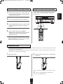
LISTENING TO RADIO BROADCASTS
1. Select the desired band.
• Manual tuning is useful when you already know the
frequency of the desired station.
• After selecting the desired band, press the TUNING
UP(+)/DOWN(-) buttons repeatedly until the right
frequency has been reached.
Auto presetting
• Auto presetting function automatically searches for FM
stations only and store them in the memory.
• While listening to FM or AM radio broadcasts, press and
hold down the (MEMORY/)ENTER button for more than 2
seconds.
• Each time this button is pressed, the band changes as
follows :
→ FM ST → FM MONO → AM
("ST" lights up) ("ST" goes off)
• When FM stereo broadcasts are poor because of weak
broadcast signals, select the FM mono mode to reduce
the noise, then FM broadcasts are reproduced in
monaural sound.
2. Press the TUNING UP(+)/DOWN(-) buttons for
more than 0.5 second.
• Then "AUTO MEM" flickers and this receiver starts auto
presetting.
• To stop auto presetting, press this button again.
• Up to 30 FM stations can be stored.
■Notes:
• FM stations of weak strength cannot be memorized.
• To memorize AM stations or weak stations, preform
"Manual presetting" procedure with using "Manual tuning"
operation.
• The tuner will now search until a station of sufficient
strength has been found. The display shows the tuned
frequency and "TUNE".
• If the station found is not the desired one, simply repeat
this operation.
• Weak stations are skipped during auto tuning.
27
ENGLISH
manual tuning
Auto tuning
RD-8504(G)_ENG_091217:RD-8504(G) 2009-12-21 오
11:36 페이지 28
manual presetting
Tuning to preset stations
ENGLISH
• You can store up to 30 preferred stations in the memory.
• After selecting the tuner as an input source, select the
desired preset number.
1. Tune in the desired station with auto or manual
tuning.
2. Press the (MEMORY/)ENTER button.
• "MEM" is flickering for several seconds.
3. Select the desired preset number (1~30) and
press the (MEMORY/)ENTER button.
• The station has now been stored in the memory.
• A stored frequency is erased from the memory by
storing another frequency in its place.
• If "MEM" goes off, start again from the above step 2.
4. Repeat the above steps 1 to 3 to memorize
other stations.
■mEmORY BACkUP FUNCTION
The following items, set before the receiver is turned off,
are memorized.
• INPUT SELECTOR settings
• Surround mode settings
• Preset stations,etc.
28
RD-8504(G)_ENG_091217:RD-8504(G) 2009-12-21 오
11:36 페이지 29
RDS Tuner(Regional Option for some countries in Europe, etc.)
RDS(Radio Data System) is a method for sending information signals together with the transmitter signals. Your tuner is
capable of translating these signals and putting the information on the display. These codes contain the following information.
Program Service name(PS), A list of Program Types(PTY), Traffic Announcement(TA), Clock Time(CT), Radio Text(RT).
■Note :
• In the other countries, RDS tuner function cannot be available.
RDS search
TP search
• Use this function to automatically search and receive
the stations offering RDS services.
• Use this function to automatically search and receive
the stations broadcasting the traffic program.
1. In the FM mode, select the RDS search mode.
1. In the FM mode, select the TP search mode.
• Each time this button is pressed, the search mode
changes as follows;
→ RDS SRCH → TP SRCH → PTY SRCH → OFF
• "TP SRCH" is displayed.
2. While displaying "TP SRCH".
2. While displaying "RDS SRCH".
• The tuner automatically searches stations broadcasting
the traffic program.
• "NO TRAFF" is displayed if the signal is too weak or
there are no stations broadcasting the traffic program.
• When "TP SRCH" is not displayed, repeat again from
the above step 1.
• The tuner automatically searches stations offering RDS
services and the station name is displayed.
• If no other RDS station is found, "NO RDS" is displayed.
• When "RDS SRCH" is not displayed, repeat again from
the above step 1.
29
ENGLISH
LISTENING TO RDS BROADCASTS(Fm ONLY)
RD-8504(G)_ENG_091217:RD-8504(G) 2009-12-21 오
11:36 페이지 30
PTY search
ENGLISH
• Use this function to automatically search and receive
the stations broadcasting the desired program type.
3. While displaying the desired program type.
1. In the FM mode, select the PTY search mode.
• The tuner automatically searches a station offering PTY
services.
• If no station is found, "NO PROG" is displayed.
• "PTY SRCH" is displayed.
2. While displaying "PTY SRCH", select the
DISPLAY
desired program type.
• In the FM mode,
• Each time the DISPLAY button is pressed, the display
mode changes as follows:
• Each time these buttons are pressed, one of 32
different types of programs is selected.
(NEWS, AFFAIRS, INFO, SPORT, EDUCATE,
DRAMA, CULTURE, SCIENCE, VARIED, POP M,
ROCK M, EASY M, LIGHT M, CLASSICS, OTHER M,
WEATHER, FINANCE, CHILDREN, SOCIAL,
RELIGION, PHONE IN, TRAVEL, LEISURE, JAZZ,
COUNTRY, NATION M, OLDIES, FOLK M,
DOCUMENT, TEST, ALARM, NONE)
Program
Program
Clock
Radio
→ Frequency → Service name → Type → Time → Text
(PS)
(PTY)
(CT)
(RT)
Volume
• When "PTY SRCH" is not displayed, repeat again from
the above step 1.
←
Surround
mode
←
Signal
input
←
• If the signals are too weak or no RDS service is
available, "NO NAME", "NO PTY", "NO TIME" or "NO
TEXT" will be displayed.
30
RD-8504(G)_ENG_091217:RD-8504(G) 2009-12-21 오
11:36 페이지 31
• The analog signals from the EXTERNAL INs as well as the digital signals from the HDMI IN, the OPTICAL or the COAXIAL
DIGITAL IN can be heard but cannot be recorded.
• When recording the analog signals from CD, F.AUX, VIDEO 2~4, be sure to select "Analog" for the Audio Mode.
(For details, refer to "When selecting the Audio Mode" on page 53.)
• The volume and tone (bass, treble) settings have no effect on the recording signals.
Dubbing from video components onto VIDEO 1
1. Select the desired of VIDEO 2(/iPod) ~ 4 as a recording source except VIDEO 1.
2. Start recording on the VIDEO 1.
3. Start play on the desired input.
• The audio and video signals from the desired input will be dubbed onto the VIDEO 1 and you can enjoy them on the TV set
and from the speakers.
■To record audio signals
• Connect the AUDIO IN/OUT jacks of "VIDEO 1" to audio recording equipment such as a tape deck, an MD recorder, etc.
and select the desired of tuner, CD, F.AUX, TAPE and VIDEO 2(/iPod)~4 as a recording source. Then you can record the
audio signals from the selected input.
31
ENGLISH
RECORDING
RD-8504(G)_ENG_091217:RD-8504(G) 2009-12-21 오
11:36 페이지 32
ENGLISH
DIGITAL AUDIO RECORDING WITH mD RECORDER
2. For digital recording, select the digital input as
• Only when the OPTICAL DIGITAL OUT of this receiver
is connected to the OPTICAL DIGITAL IN of the MD
recorder or CD recorder, you can enjoy high-quality
sound of digital recording without converting the original
signals. Refer to "CONNECTING VIDEO
COMPONENTS", "CONNECTING AUDIO
COMPONENTS" and "CONNECTING DIGITAL INS
AND OUT" on pages 5 ~7 and the operating instructions
of the MD recorder or CD recorder.
recording signal input.
■Notes:
• The digital audio signals input into the OPTICAL and the
COAXIAL DIGITAL INs (, not the HDMI INs) can be
output from the OPTICAL DIGITAL OUT.
• Depending on the digital audio signal format, some
digital signals cannot be output from the OPTICAL
DIGITAL OUT.
• Digital recording is available for the digital audio
program sources such as CDs, MDs, some DVDs, etc.
• There are some restrictions on recording digital signals.
When making digital recordings, refer to the operating
instructions of your digital recording equipment to know
what restrictions are imposed.
■Note :
1.
• If the Audio Mode is set to the mode other than "Digital"
for the corresponding recording source on the INPUT
SETUP menu, the digital audio signals from the selected
digital input will not be output and there will be no
recording. (For details, refer to "When CD, F.AUX,
VIDEO 1~4, EXT.IN is selected as an input source" on
page 20 and "When selecting the Audio Mode" on page
53.)
Select the desired of CD, F.AUX, VIDEO 1~4,
EXT.IN as a recording source.
3. Start recording on the component connected to
the OPTICAL DIGITAL OUT.
4. Start play on the desired input.
32
RD-8504(G)_ENG_091217:RD-8504(G) 2009-12-21 오
11:36 페이지 33
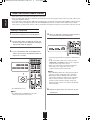
OTHER FUNCTIONS
• The sleep timer allows the system to continue to operate for a specified period of time before automatically shutting off.
• To set the receiver to automatically turn off after the specified period of time.
• Each time this button is pressed, the sleep time changes
as follows:
→ 10 → 20 → 30 → --- → 90 → OFF
Unit : minutes
• While operating the sleep timer, "
" lights up.
• When the sleep time is selected, the fluorescent display is
dimly lit.
Adjusting the brightness of the fluorescent display
• Each time this button is pressed, the brightness of the
fluorescent display changes as follows:
→ ON → dimmer → OFF
• In the display OFF mode, pressing any button will restore
the display ON mode.
Displaying the operation status
During playback,
• Each time this button is pressed, the display mode
changes as follows:
→
Signal
Input
→
Surround
mode
→
Volume
→
Input
source
• When RDS tuner function is available in your country, for
details on the FM mode information, see “DISPLAY” on
page 30.
33
ENGLISH
Operating the sleep timer
RD-8504(G)_ENG_091217:RD-8504(G) 2009-12-21 오
11:36 페이지 34
ROOm 2 SOURCE PLAYBACk
ENGLISH
• This function allows enjoying one source in the main room and playing another in a different room at the same time.
■Notes:
• The analog signals from the EXTERNAL INs and the digital signals cannot be output to the different room, meaning no
playback in a different room.
• Only the (composite) video signals can be output to the different room.
• When the EXTERNAL IN is selected as a main input, if the MAIN source is selected as a ROOM 2 input, no audio signal can be
heard in the different room (ROOM 2).
• Even when this receiver enters the standby mode, in such a case that only the "R2" lights up still, meaning only the ROOM 2
circuitry operates, the ROOM 2 source can be played independently.
• When you do not use the ROOM 2 function, turn off the ROOM 2 function to save electricity.
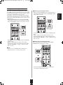
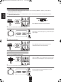
When using the buttons on the front panel
1. Press the ROOM 2 button to enter the ROOM 2 mode.
• ROOM 2 ~ is displayed for several seconds.
• When the ROOM 2 setting mode disappears, press the
ROOM 2 button again.
2. Select the desired mode while displaying the ROOM 2 setting mode.
• Each time these buttons are pressed, the mode changes
as follows :
→ ROOM 2 ~ : To turn on or off the ROOM 2 function.
(ROOM 2 mode)
↕
IN ~
: To select the desired ROOM 2 source.
(ROOM 2 input)
↕
→ VOL ~
: To adjust the volume on the power
(ROOM 2 volume) amplifier assigned to "Surr Back↔
Room 2" or "Room 2".
■Note :
• When the ROOM 2 mode is set to OFF, the ROOM 2 input
and the ROOM 2 volume cannot be selected.
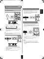
3. Set the selected mode as desired.
■When selecting the ROOm 2 mode.
ON : To turn on the ROOM 2 function.
↕ ("R2" lights up.)
OFF : To turn it off. ("R2" goes off.)
■When selecting the ROOm 2 input.
• You can select the desired among MAIN source, TUNER, CD, F.AUX, TAPE, VIDEO 1 ~ VIDEO 4 as a ROOM 2 source.
■When selecting the ROOm 2 volume.
• You can adjust the volume on the power amplifier assigned to "Surr Back↔Room 2" or "Room 2" when the ROOM 2
speaker terminals are connected to the speakers in a different room. (For details, refer to "When selecting the AMP Assign"
on page 41.)
4. Start play on the component related to the ROOM 2 source.
34
RD-8504(G)_ENG_091217:RD-8504(G) 2009-12-21 오
11:36 페이지 35
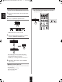
When using the buttons on the remote control unit
• ROOM 2 ~ is displayed for several seconds.
• Each time the button is pressed, the ROOM 2 mode
changes as follows :
ON : To turn on the ROOM 2 function.
↕ ("R2" lights up.)
OFF : To turn it off. ("R2" goes off)
■Note :
• When ROOM 2 mode is set to OFF, the ROOM 2 volume
cannot be selected.
2. Select the desired input as a ROOM 2 source.
• Each time the “INPUT” button is pressed, the ROOM 2
input can be selected among MAIN source, TUNER, CD,
F.AUX, TAPE, VIDEO 1 ~ VIDEO 4 as a ROOM 2 source.
3. Adjust the ROOM 2 volume.
• You can adjust the volume on the power amplifier
assigned to “Surr Back↔Room 2” or “Room 2”. (For
details, refer to “When selecting the AMP ASSIGN” on
page 41.)
4. Start play on the component related to the ROOM 2 source.
35
ENGLISH
1. Turn on the ROOM 2 function.
RD-8504(G)_ENG_091217:RD-8504(G) 2009-12-21 오
11:36 페이지 36
ENGLISH
OSD Menu Settings
• The OSD (On-Screen Display) menu is a setting menu that is displayed on the monitor TV and allows you to perform the setup
procedures easily. In most situations, you will only need to set this once during the installation and layout of your home theater, and it
rarely needs to be changed later.
The OSD menu consists of 6 main menus ; system setup, speaker/room EQ setup, input setup, multi room setup, sound parameter
and advanced video . These menus are then divided up into various sub-menus.
■Notes:
• The OSD menu and the momentary OSD can be displayed via the HDMI MONITOR OUT only.
However, when the Video Scaling is set to HDMI Bypass and the video signals are input into the HDMI IN, the momentary OSD
cannot be displayed via the HDMI MONITOR OUT. (For details, refer to “When selecting the Video Scaling” on page 53.)
• When performing the OSD menu operation, the corresponding operation status is displayed on the unit’s fluorescent display, too.
Therefore, in such a case that the OSD menu cannot be displayed on your TV, perform the setup precedure, viewing the
corresponding operation status on the fluorescent display. (For details on setup menu, refer to “Setup menu flow” on page 38.)
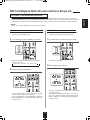
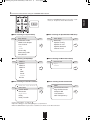
■Navigating through the OSD menu
• The explanations here assume you are using the buttons on the remote control when performing the OSD menu operation.
However, you can use the buttons on the front panel as well.
The buttons on the front panel correspond to those on the remote control as shown below.
1. Turn the menu screen on.
EXIT
System Setup
Speaker/Room EQ Setup
Input Setup
Multi Room Setup
Sound Parameter
Advanced Video
• The main menu will be shown.
• To turn the menu screen off, press this button again.
2. Select the desired menu using the CURSOR UP/DOWN buttons.
36
NEXT
RD-8504(G)_ENG_091217:RD-8504(G) 2009-12-21 오
11:36 페이지 37
• When the CURSOR LEFT button is pressed on a submenu, etc. the previous menu will be returned.
■When selecting the System Setup
BACK
Amp Assign
Subwoofer mode
HDMI Audio Output
Tone Control
Bass
Treble
Cinema EQ
Momentary OSD
Save/Recall
■When selecting the Speaker/Room EQ Setup
NEXT
BACK
40
■When selecting the Input Setup
BACK
VIDEO 1
V2/iPod
VIDEO 3
VIDEO 4
CD
TAPE
F.AUX
TUNER
EXT.IN
BACK
NEXT
43
■When selecting the multi Room Setup
BACK
NEXT
Room 2 Set
Input
Volume
51
NEXT
56
■When selecting the Sound Parameter
Dolby Pro Logic II Music
Panorama
Center Width
Dimension
Night Mode
Dolby
Dolby TrueHD
Auto Setup
Room EQ
Speaker Config
Speaker X-over
Speaker Distance
Channel Level
■When selecting the Advanced Video
BACK
NEXT
57
PReP
Detail Enhancement
Edge Enhancement
Mosquito NR
Test Patterns
OSD Transparency
• For the setting details, see page in
.
• Adjust the setting(s) in each setting category to your preference.
• When the SETUP button is pressed on a sub-menu, the menu screen will be turned off.
37
NEXT
58
ENGLISH
3. Enter the selected menu using the CURSOR RIGHT button.
RD-8504(G)_ENG_091217:RD-8504(G) 2009-12-21 오
11:36 페이지 38
Setup menu flow
: Default settings
ENGLISH
SYSTEM
AMP ASSG (Amp Assign)
AMP : B / R2 (Surr Back ȧRoom 2) / BI-A (Bi Amp) /
SW MODE (Subwoofer Mode)
SW M : NORM (Normal) / SW+ (Subwoofer Plus +)
HDMI AUD (HDMI Audio Output)
HDMI : SPK (Speaker) / PASS (HDMI Passthrough)
TONE (Tone Control)
TONE : OFF / ON
BACK (Surround Back) / R2 (Room 2)
(System Setup)
BASS
BASS : 0 dB / -10 ~ +10
TREBLE
TRBL : 0 dB / -10 ~ +10
C-EQ (Cinema EQ)
C-EQ : OFF / ON
OSD (Momentary OSD)
OSD : ON / OFF
SAV/RECA (Save/Recall)
SAVE 1 / SAVE 2 / RECALL 1 ~ 2
SPK / EQ
AUTO SET (Auto Setup)
START*1
(Speaker / Room EQ Setup)
ROOM EQ
MODE : OFF / ON
CONFIG
CENTER
CENTER Y (Yes) / N (No)
(Speaker Configuration)
SURR (Surround)
SURR Y (Yes) / N (No)
BACK (Surr Back)
BACK 2CH (channel) / 1CH / N (No)
SUB-W (Subwoofer)
SUB-W Y (Yes) / N(No)
X-OVER
FRONT
F : 80 Hz / FULL (Full Range), 40 ~ 250
(Speaker Crossover)
CENTER
C : 80 Hz / FULL, 40 ~ 250
SURROUND
S : 80 Hz / FULL, 40 ~ 250
SURRBACK (Surr Back)
B / M : 80 Hz / FULL, 40 ~ 250
DISTANCE
UNIT
(Speaker Distance)
CH LEVEL
MODE
UNIT : M (Meter) / FT (Feet)
FL : 3 M / 0 ~ 9 (10 FT / 0 ~ 30)*2
FRONT L (Front Left)
CENTER
C : 3 M / 0 ~ 9 (10 FT / 0 ~ 30)*2
FRONT R (Front Right)
FR : 3 M / 0 ~ 9 (10 FT / 0 ~ 30)*2
SURR R (Surround Right)
SR : 1.5 M / 0 ~ 9 (5 FT / 0 ~ 30)*2
SURB R (Surr Back Right)
BR : 1.5 M / 0 ~ 9 (5 FT / 0 ~ 30)*2
SURB L (Surr Back Left)
BL : 1.5 M / 0 ~ 9 (5 FT / 0 ~ 30)*2
SURR L (Surround Left)
SL : 1.5 M / 0 ~ 9 (5 FT / 0 ~ 30)*2
SUBW (Subwoofer)
SW : 1.5 M / 0 ~ 9 (5 FT / 0 ~ 30)*2
MODE : SAV1 (Save1) / CAL (Calibrate) /
SAV2 / RCL 1 ~ 2 (Recall 1 ~ 2)
(Channel Level)
FRONT L (Front Left)
FL 0 dB / -15 ~ +15
CENTER
C 0 dB / -15 ~ +15
FRONT R (Front Right)
FR 0 dB / -15 ~ +15
SURR R (Surround Right)
SR 0 dB / -15 ~ +15
SURB R (Surr Back Right)
BR 0 dB / -15 ~ +15
SURB L (Surr Back Left)
BL 0 dB / -15 ~ +15
SURR L (Surround Left)
SL 0 dB / -15 ~ +15
SUBW (Subwoofer)
SW 0 dB / -15 ~ +15
LFE LVL (LFE Level)
DOLBY
DTS
38
DOLBY 0 dB / -10 ~ 0
DTS 0 dB / -10 ~0
11:36 페이지 39
INPUT*3
VID1 CFG
RE-NAME*1
(Input Setup)
(VIDEO1 Configuration)
HDMIASSG (HDMI Assign)
HDMI : HD1 ~ 3 (HDMI 1 ~ 3) / - - -
V2IPDCFG
CPN ASSG (Component Assign)
CPN : CPN1 ~ 2 (Component 1 ~ 2) / - - -
(VIDEO2/iPod Configuration)
AUD ASSG (Audio Assign)
AUD : OPT1 ~ 2 (Optical 1 ~ 2) /
VID3 CFG
COX1 ~ 2 (Coaxial 1 ~ 2) / - - V.MODE : AT (Auto) / HD (HDMI) /
VID MODE (Video Mode)
(VIDEO3 Configuration)
CPN (Component) / SVD (S-Video) /
VID4 CFG (VIDEO4 Configuration)
CPS (Composite)
CD CFG (CD Configuration)
TAPE CFG (TAPE Configuration)
AUD MODE (Audio Mode)
A.MODE : AT (Auto) / HD (HDMI) /
VID SCAL (Video Scaling)
AUTO / BYPASS (HDMI Bypass) / 576P /
DG (Digital) / AN (Analog)
F.AUX CFG
(F.AUX Configuration)
720P / 1080I / 1080P
EXTIN CFG
(EXTERNAL IN Configuration)
AV SYNC
SYNC : 0 ms / 0 ~ 200
HD AUDIO
HD A : ON / OFF
MLT ROOM
R2 SET (Room2 Set)
ROOM2 : OFF / ON
(Multi Room Setup)
R2 INPUT (Room2 Input)
IN : MAIN / VID 1 ~ 4 (Video1 ~ 4) / CD / TAPE / F.AUX / TUNER
R2 VOL (Room2 Volume)
VOL : 30 dB / MIN (0) ~ MAX (80)
PARAMTR
PANORAMA
(Sound Parameter)
C-WIDTH (Center Width)
PANO : OFF / ON
DIMEN (Dimension)
C.WIDTH : 3 / 0 ~ 7
DIMEN : 0 / -3 ~ +3
DRC DD (Dynamic Range Compression Dolby)
DRC : OFF / LOW / MID / HIGH
DRC THD (Dynamic Range Compression Dolby TrueHD)
ADV. VID
PREP (Progressive Reprocessing)
(Advanced Video)
DET ENHA (Detail Enhancement)
DRC : AUTO / OFF / LOW / MID / HIGH
PREP : OFF / AUTO
D. ENH : 0 / -10 ~ +10
EDGE (Edge Enhancement)
EDGE : 0 / -10 ~ +10
MOSQ NR (Mosquito NR)
NR : OFF / LOW / HIGH
TEST PAT (Test Patterns)
OFF / FRM GMTY (Frame Geometry) / BRTCNTRS (Bright /
Contrast) / CHKBOARD (Checker Board) / VRTILINE (Vertical Lines) /
HORILINE (Horizontal Lines) / JUDDER / BARS75 (Color8 Bars 75) /
BARS100 (Color8 Bars 100)
TRANSPAR (OSD Transparency)
OSD : LOW / MID / HIGH
*1 : For the setting details, refer to the corressponding operating instructions on the OSD Menu Settings.
*2 : These are the setting values when the UNIT is set to FT (Feet).
*3 : Depending on the input source, some items cannot be selected.
39
ENGLISH
RD-8504(G)_ENG_091217:RD-8504(G) 2009-12-21 오
RD-8504(G)_ENG_091217:RD-8504(G) 2009-12-21 오
11:36 페이지 40
SETTING THE SYSTEm SETUP
ENGLISH
BACK
Amp Assign
Subwoofer mode
HDMI Audio Output
Tone Control
Bass
Treble
Cinema EQ
Momentary OSD
Save/Recall
NEXT
• AMP Assign : To assign the surround back channels' power
amplifier correctly depending on how to use the
speakers.
• Subwoofer Mode : To select the desired subwoofer mode.
• HDMI Audio Output : To output the digital audio signals from the
HDMI MONITOR OUT connector.
• Tone Control : To adjust the tone (bass and treble) as desired.
• Cinema EQ : To select the desired cinema EQ mode.
• Momentary OSD : To turn on or off the OSD that shows the
status corresponding to each operation
momentarily.
• Save/Recall : To memorize all the OSD menu setting values into
memory or to recall the memorized setting values.
1. Press the CURSOR UP/DOWN buttons to select the desired item, then press the CURSOR RIGHT button to
enter its setting menu.
2. Press the CURSOR UP/DOWN buttons to set the selected item as desired, then press the ENTER button.
• Then the setting value is marked with “ OK ”.
• When the CURSOR LEFT(◀) button is pressed on a
setting menu, the previous menu will be returned to.
40
RD-8504(G)_ENG_091217:RD-8504(G) 2009-12-21 오
11:36 페이지 41
Continued
When selecting the AmP Assign
Surr Back ↔ Room 2 : When connecting this receiver to the surround back speakers and the ROOM 2 speakers both, the
↕
power amplifier automatically drives the surround back speakers or the ROOM 2 speakers
depending on whether the ROOM 2 function is turned off or on.
Bi AMP : To drive the front bi-amp capable speakers when connecting the FRONT and the SURROUND BACK/MULTI
↕
channels to them.
Surround Back : To drive the surround back speakers when connecting the SURROUND BACK/MULTI channels to them.
↕
Room 2 : To drive the ROOM 2 speakers when connecting the ROOM 2 channels to them.
When selecting the Subwoofer mode
• "Subwoofer Plus+" mode is valid only when "Front" and "Center" are set to "Full Range" and "Subwoofer" is set to "Yes" on the
Speaker/Room EQ Setup menu. (For details, refer to "SETTING THE SPEAKER/ ROOM EQ SETUP" on page 43.)
Normal : When the low frequency signals of channels set to "Full Range " are reproduced from those channels only. In this
mode, the low frequency signals that are reproduced from the subwoofer channel is only the low frequency signals of
↕ LFE (from the multi-channel sources that contains LFE (Low Frequency Effects) channel, also called the ".1" channel)
and the channels set to the setting value other than "Full Range".
Subwoofer Plus+ : When the low frequency signals of channels set to "Full Range" are reproduced simultaneously from those
channels and the subwoofer channel.
In this mode, the low frequency range expands more uniformly through the room, but depending on the size
and shape of the room, interference may result in a decrease of the actual volume of the low frequency
range.
When selecting the HDmI Audio Output
• The HDMI connection can carry uncompressed digital video signals and digital audio signals.
Depending on whether the digital audio signals input into the HDMI IN are output from the HDMI MONITOR OUT of this
receiver or not, you should set the HDMI Audio Output correctly.
Speaker : Not to output the HDMI digital audio signals from the HDMI MONITOR OUT of this receiver, meaning these signals
↕
are heard from the speakers connected to this receiver.
HDMI Passthrough : To output the HDMI digital audio signals from the HDMI MONITOR OUT, meaning these signals are heard
from the speakers of your TV.
■Note:
• When the HDMI Audio Output is set to HDMI Passthrough, no sound will be heard from the speakers connected to this
receiver (except ROOM 2 speakers) even though any input source is selected.
When selecting the Tone Control
On : To adjust the tone for your taste. ("DIR" goes off.)
↕
Off : To listen to a program source without the tone effect. ("DIR" lights up.)
■When adjusting the tone (Bass and Treble)
• You can adjust the tone only when the Tone Control is set to On.
① Press the CURSOR UP/DOWN buttons to select the desired tone, then press the CURSOR RIGHT button to
enter its setting menu.
② Press the CURSOR UP/DOWN buttons to adjust the selected tone as desired.
• The tone level can be adjusted within the range of -10 ~ +10 dB.
• In general, we recommend the bass and treble to be adjusted to 0 dB (flat level).
• Extreme settings at high volume may damage your speakers.
41
ENGLISH
• The surround back channels' power amplifier can drive the surround back speakers, the ROOM 2 speakers or the front bi-amp
capable speakers. Depending on how to use the speakers, you should assign the power amplifier correctly. (For details, refer
to "CONNECTING SPEAKERS" on page 8 and "CONNECTING ROOM 2 OUTS" on page 10.)
RD-8504(G)_ENG_091217:RD-8504(G) 2009-12-21 오
11:36 페이지 42
Continued
ENGLISH
When selecting the Cinema EQ
On : To compensate for edgy or shrill movie sound tracks.
↕
Off : To turn off the cinema EQ function.
When selecting the momentary OSD
On : To turn on the OSD function that shows the status corresponding to each operation on this unit momentarily.
↕
Off : To turn it off.
■Note :
• The OSD menu and the momentary OSD can be displayed via the HDMI MONITOR OUT only.
However, when the Video Scaling is set to the HDMI Bypass, they cannnot be displayed via the HDMI MONITOR OUT.
(For details, refer to “When selecting the Video Scaling” on page 53.)
When selecting the Save/Recall
• You can memorize all the OSD menu setting values into memory 1(“Save 1”) or memory 2(“Save 2”) and recall the
memorized setting values whenever you want.
Save 1 : To memorize all the OSD menu setting values into memory 1.
↕
Save 2 : To memorize them into memory 2.
↕
Recall 1 : To recall the setting values memorized into memory 1.
↕
Recall 2 : To recall the setting values memorized into memory 2.
42
RD-8504(G)_ENG_091217:RD-8504(G) 2009-12-21 오
11:36 페이지 43
• After you have installed this receiver and connected all the components, you should adjust the speaker settings for the
optimum sound acoustics according to your environment and speaker layout.
• Even when you change speakers, speaker positions, or the layout of your listening environment, you should adjust the
speaker settings, too.
• When performing the Auto Setup procedure, you need not perform the Speaker Configuration, Speaker Crossover, Speaker
Distance and Channel Level setup procedures.
BACK
Auto Setup
Room EQ
Speaker Config
Speaker X-over
Speaker Distance
Channel Level
NEXT
• Auto Setup : To set the speaker setup and channel level setup
automatically.
• Room EQ : To select the desired room EQ mode.
• Speaker Configuration : To adjust the speakers depending on
whether they are connected or not.
• Speaker Crossover : To select the desired crossover frequency.
• Speaker Distance : To select the distance between the listening
position and each speaker to set the delay
time automatically for optimum surround
playback.
• Channel Level : To adjust the channel levels as desired or to
memorize them into the preset memory.
When selecting the Auto Setup
• Auto Setup lets you avoid troublesome listening-based speaker setup and achieve good surround sound. Auto Setup has the
feature that provides the optimum listening environment at the listening position in your room.
You should connect the supplied microphone to the SETUP MIC jack so that this receiver can analyze the information from a
series of test tones emitted from speakers at main listening position and can adjust the configuration, distance, sound level,
crossover frequency and frequency response of each speaker automatically.
• If you want to personalize your speaker setup and channel level setup by making the settings manually, perform the "When
selecting the Speaker Configuration" on page 46, "When selecting the Speaker Crossover" on page 47, "When selecting the
Speaker Distance" on page 48 and "When Selecting the Channel Level" on page 49.
• After the auto setup has been completed, set the room EQ as desired. (For details, refer to "When selecting the Room EQ" on
page 45.)
■Preparations
①. Check that the speakers are securely connected to this receiver.
• If your subwoofer has adjustable volume and crossover frequency, set the volume halfway and set the crossover
frequency to the maximum or the low pass filter off.
②. Connect the supplied microphone to the SETUP MIC jack on the front panel.(For details, refer to "SETUP MIC JACK" on
page 12.)
■Notes :
• Because the microphone for Auto Setup is designed for use with this receiver, to use the auto setup function, do not use a
microphone other than the one supplied with this receiver.
• After you have completed the auto setup procedure, disconnect the microphone.
1. Place the microphone on a flat level surface at the listening position.
• If possible, use a tripod, etc. to attach the microphone at the same height as your ears would be when you are seated in your
listening position.
• Ensure there are no obstacles between the speakers and the microphone.
43
ENGLISH
SETTING THE SPEAkER / ROOm EQ SETUP
RD-8504(G)_ENG_091217:RD-8504(G) 2009-12-21 오
11:36 페이지 44
Continued
2. Press the CURSOR UP/DOWN buttons to select the Auto Setup, then press the CURSOR RIGHT button.
ENGLISH
BACK
Before starting the system,
please plug the MIC. in using
the front panel jack.
NEXT
<<Warning>>
The test tone is LOUD.
3. Press the CURSOR RIGHT button to start the auto setup procedure.
When the auto setup has been completed.
CANCEL
COMPLETED
APPLY
• Loud test tones are output successively and then if a series of auto setup procedure has been completed, "COMPLETED"
will be displayed.
• To stop the auto setup procedure while performing it, press the CURSOR LEFT button.
In such a case that the auto setup procedure is stopped before "COMPLETED" is displayed, the results of each adjustment
can not be memorized.
• If there may be a problem with speaker or microphone connection, error message will be displayed. In this case, turn off the
power, check the connection and then retry the auto setup procedure.
■Notes :
• Because the test tones are loud, ensure there no infants or small children in the room.
• For best results, ensure the room is as quiet as possible during the auto setup procedure.
If there is too much ambient noise, the results may not be satisfactory.
4. To memorize the results, press the CURSOR RIGHT button.
• Then the results are memorized and the Speaker/Room EQ Setup menu is displayed.
• When the CURSOR LEFT button is pressed to select “CANCEL”, the results are not memorized.
• Check the results on each setup menu(Speaker Configuration menu on page 46, Speaker Crossover menu on page 47,
Speaker Distance menu on page 48 and Channel Level menu for "Calibrate" mode) on page 49).
• If the results are not satisfactory, you can retry the auto setup procedure or personalize your speaker setup and channel
level setup by making the settings manually. (For details, refer to "When selecting the Speaker Configuration" on page 46,
"When selecting the Speaker Crossover" on page 47, "When selecting the Speaker Distance" on page 48 and "When
selecting the Channel Level" on page 49.)
44
RD-8504(G)_ENG_091217:RD-8504(G) 2009-12-21 오
11:36 페이지 45
• The room EQ is a kind of room equalizer for your speakers. According to the acoustic characteristics of your room
measured by the auto setup, the room EQ automatically adjusts the frequency response of your speakers.
• If you use different brands or sizes of speakers for some channels or have a room with unique acoustic characteristics,
such as walls, furniture, and the dimensions or the shape of the room, we recommend using the room EQ.
■Note :
• To use the room EQ, first you should finish measuring the acoustic characteristics of your room performing the auto setup.
(For details, refer to "When selecting the Auto Setup" on page 43.)
1. Press the CURSOR UP/DOWN buttons to select the Room EQ, then press the CURSOR RIGHT button to
enter the setting menu.
BACK
OK
On
Off
2. Press the CURSOR UP/DOWN buttons to select the desired room EQ mode, then press the ENTER button.
On : To adjust the frequency response of all speakers to the flattest response.
↕
Off : To turn off the room EQ.
• When the CURSOR LEFT button is pressed on the setting menu, the previous menu will be returned to.
45
ENGLISH
When selecting the Room EQ
RD-8504(G)_ENG_091217:RD-8504(G) 2009-12-21 오
11:36 페이지 46
When selecting the Speaker Configuration
1. Press the CURSOR UP/DOWN buttons to select the Speaker Configuration, then press the CURSOR RIGHT
ENGLISH
button to enter the setting menu.
BACK
Front
Center
Surround
Surr Back
Subwoofer
NEXT
2. Press the CURSOR UP/DOWN buttons to select the desired speaker, then press the CURSOR RIGHT
button to enter its setting menu.
3. Press the CURSOR UP/DOWN buttons to set the selected speaker as desired, then press the ENTER button.
Yes/No: Select the desired depending on whether the speakers are connected or not.
2 Channel/1 Channel (Left) : Select the desired depending on the number of speakers connected to SURROUND BACK/
MULTI channels.
• When the CURSOR LEFT button is pressed on the setting menu, the previous menu will be returned to.
■Notes :
• When speakers are not set to "No", you should set their distances from listening position and crossover frequencies
according to their frequency characteristics. (For details, refer to "When selecting the Speaker Crossover" on page 47 and
"When selecting the Speaker Distance" on page 48.)
• When the "Surround" is set to "No", "Surr back" cannot be set to "2 Channel" or "1 Channel(Left)".
• When the surround back channels' power amplifier is assigned to "Bi AMP" or "Room 2", the "Surr Back" cannot be
selected. (For details, refer to "When selecting the AMP Assign" on page 41.)
4. Repeat the above steps 2 and 3 until the speakers are all set as desired.
46
RD-8504(G)_ENG_091217:RD-8504(G) 2009-12-21 오
11:36 페이지 47
• Set the crossover frequency according to the frequency characteristics of the speakers connected.
(For details on the frequency characteristics, refer to the operating instructions of the speakers.)
• If the frequency range of your speaker is 100 Hz ~ 20 kHz, the crossover frequency should be set to 100 Hz (or slightly
higher).
• The low frequencies below the crossover frequency are to output from subwoofer or the speakers which are set to "Full
Range" (when not using a subwoofer).
1.
Press the CURSOR UP/DOWN buttons to select the Speaker X-over, then press the CURSOR RIGHT button
to enter the setting menu.
BACK
Front
Center
Surround
Surr Back
NEXT
2. Press the CURSOR UP/DOWN buttons to select the desired speaker, then press the CURSOR RIGHT
button to enter its setting menu.
■Note :
• You cannot select the subwoofer and the speakers set to "No".
3. Press the CURSOR UP/DOWN buttons to set the crossover frequency as desired, then press the ENTER
button.
• You can adjust the crossover frequency within the range of 40 ~ 250 Hz.
• Select "Full Range" when the selected speaker can fully reproduce the low frequencies below 40 Hz.
• When the CURSOR LEFT button is pressed on the setting menu, the previous menu will be returned to.
4. Repeat the above steps 2 and 3 until the crossover frequencies are all set as desired.
47
ENGLISH
When selecting the Speaker Crossover
RD-8504(G)_ENG_091217:RD-8504(G) 2009-12-21 오
11:36 페이지 48
When selecting the Speaker Distance
1. Press the CURSOR UP/DOWN buttons to select the Speaker Distance, then press the CURSOR RIGHT
ENGLISH
button to enter the setting menu.
BACK
UNIT
Front Left
Center
Front Right
Surround Right
Surr Back Right
Surr Back Left
Surround Left
Subwoofer
NEXT
2. Press the CURSOR UP/DOWN buttons to select the desired item, then press the CURSOR RIGHT button to
enter its setting menu.
■Note :
• You cannot select the speakers set to "No".
3. Press the CURSOR UP/DOWN buttons to set the selected item as desired, then press the ENTER button.
■When selecting the desired unit
• You can select either Meter or Feet.
• Once a unit is selected, the distances are automatically changed in the selected unit.
■When setting the distance
• You can set the distance within the range of 0 ~ 9.0 meters in 0.1 meter intervals (or 0 ~ 30 feet in 0.5 feet intervals).
• When setting the distance, use the CURSOR UP/DOWN buttons only.
• When the CURSOR LEFT button is pressed on the setting menu, the previous menu will be returned to.
4. Repeat the above steps 2 and 3 until the distances are all set as desired.
■About the speaker distance
When enjoying multi-channel surround playback with Dolby Digital and DTS sources, etc., it is ideal that the center, surround
and surround back speakers etc. should be the same distance from the main listening position as the front speakers. By
entering the distance between the listening position and each speaker, the delay times of center, surround and surround back
speakers, etc. are automatically adjusted to create an ideal listening environment virtually as if the center, surround and
surround back speakers, etc. were at their ideal locations respectively.
48
RD-8504(G)_ENG_091217:RD-8504(G) 2009-12-21 오
11:36 페이지 49
• You can adjust the current channel levels as desired. These adjusted levels are just memorized into user’s memory
("Calibrate"), not into preset memory("Save 1(Movie)", "Save 2(Music)").
• After adjusting each channel level with test tone, adjust the channel levels either according to the program sources or to suit
your tastes.(For details, refer to "Adjusting each channel level with test tone" on page 24.)
1.
Press the CURSOR UP/DOWN buttons to select the Channel Level, then press the CURSOR RIGHT button
to enter the setting menu.
BACK
MODE
Front Left
Center
Front Right
Surround Right
Surr Back Right
Surr Back Left
Surround Left
Subwoofer
LFE
NEXT
2. Press the CURSOR UP/DOWN buttons to select the desired channel(, not “MODE”), then press the
CURSOR RIGHT button to enter its setting menu.
■When selecting the LFE
• Press the CURSOR UP/DOWN buttons to select the desired program source’s LFE, then press the CURSOR RIGHT
button to enter its setting menu.
■Note :
• Depending on the speaker settings(“No”, etc.), some channels cannot be selected.
3. Press the CURSOR UP/DOWN buttons to adjust the level of the selected channel or program source’s LFE
as desired.
• The LFE level can be adjusted within the range of -10 ~ 0 dB and other channel levels within the range of -15 ~ +15 dB
• In general, we recommend the LFE level to be adjusted to 0 dB.(However, the recommended LFE level for some early DTS
software is -10 dB.) If the recommended levels seem too high, lower setting as necessary.
• When the CURSOR LEFT button is pressed on the setting menu, the previous menu will be returned to.
4. Repeat the above steps 2 and 3 to adjust each channel level.
49
ENGLISH
When selecting the Channel Level
RD-8504(G)_ENG_091217:RD-8504(G) 2009-12-21 오
11:36 페이지 50
Continued
ENGLISH
■memorizing the adjusted channel levels and recalling them.
• You can memorize the adjusted channel levels into preset memory(“Save 1(Movie)”, “Save 2(Music)”) and recall the
memorized whenever you want.
1.
Press the CURSOR UP/DOWN buttons to select the MODE on the Channel Level menu, then press the
CURSOR RIGHT button to enter the setting menu.
2. Press the CURSOR UP/DOWN buttons to select the desired mode, then press the ENTER button.
Calibrate : To memorize the adjusted channel levels into user’s memory.
↕
Save 1(Movie) : To memorize the adjusted channel levels into memory 1.
↕
Save 2(Music) : To memorize them into memory 2.
↕
Recall 1(Movie) : To recall the channel levels memorized into memory 1.
↕
Recall 2(Music) : To recall the channel levels memorized into memory 2.
50
RD-8504(G)_ENG_091217:RD-8504(G) 2009-12-21 오
11:36 페이지 51
SETTING THE INPUT SETUP
VIDEO 1
V2/iPod
VIDEO 3
VIDEO 4
CD
TAPE
F.AUX
TUNER
EXT.IN
NEXT
• This menu allows you to make the various settings
depending on how to use the input sources connected to
this receiver.
When selecting the items other than Re-Name
1. Press the CURSOR UP/DOWN buttons to select the desired input source, then press the CURSOR RIGHT
button to enter the setting menu.
Example: When selecting the VIDEO 1
BACK
Re-Name
HDMI Assign
Component Assign
Audio Assign
Video Mode
Audio Mode
Video Scaling
AV Sync
HD Audio
NEXT
2. Press the CURSOR UP/DOWN buttons to select the desired item, then press the CURSOR RIGHT button to
enter its setting menu.
■Note :
• Depending on the input source, some items cannot be selected.
3. Press the CURSOR UP/DOWN buttons to set the selected item as desired, then press the ENTER button.
• When the CURSOR LEFT button is pressed on the setting menu, the previous menu will be returned to.
• When adjusting the AV Sync, use the CURSOR UP/DOWN buttons only.
51
ENGLISH
BACK
RD-8504(G)_ENG_091217:RD-8504(G) 2009-12-21 오
11:36 페이지 52
Continued
ENGLISH
■When selecting the HDmI Assign
• You should assign the connected HDMI INs to the desired of VIDEO 1 ~ VIDEO 4, EXT.IN.
(For details, refer to "CONNECTING VIDEO COMPONENTS" on pages 5 ~ 6.)
• You can select the desired of HDMI 1 ~ HDMI 3.
■Note :
• In such a case that a HDMI IN is assigned to two input sources or more, when these input sources are selected, the
uncompressed digital video signals (and digital audio signals when the HDMI Audio Output is set to HDMI Passthrough) input
into the same HDMI IN can be output from the HDMI MONITOR OUT of this receiver.
■When selecting the Component Assign
• You should assign the connected COMPONENT VIDEO INs to the desired of VIDEO 1 ~ 4, EXT.IN.
(For details, refer to "CONNECTING VIDEO COMPONENTS" on pages 5 ~ 6.)
• You can select the desired of Component 1 ~ 2.
■Note :
• In such a case that a COMPONENT VIDEO IN is assigned to two input sources or more, when these input sources are
selected, the component video signals can be viewed from the same COMPONENT VIDEO IN.
■When selecting the Audio Assign
• You should assign the connected DIGITAL INs to the desired of CD, F.AUX and VIDEO 1 ~ VIDEO 4, EXT.IN.
(For details, refer to "CONNECTING DIGITAL INS AND OUT" on page 7.)
• You can select the desired of Optical 1 ~ 2 and Coaxial 1 ~ 2.
■Note :
• In such a case that a DIGITAL IN is assigned to two input sources or more, when these input sources are selected, the digital
audio signals can be heard from the same DIGITAL IN.
■When selecting the Video mode
• Depending on the Video Mode settings, the video input signal can be converted and output from the HDMI MONITOR OUT.
Auto : When there are multiple video input signals, the video input signals are detected and the video input signal to be output
↕ from the HDMI MONITOR OUT is selected automatically in the priority order of them :
"HDMI" > "COMPONENT" > "S-VIDEO" > "(composite) VIDEO"
HDMI : The signal that is input into the HDMI IN connector is always played. The HDMI video input signal is output from the
HDMI MONITOR OUT only.
↕
Component : The signals that are input into the COMPONENT IN jacks are always played.
The component video signals are converted and output from the HDMI MONITOR OUT.
↕
S-Video : The signal that is input into the S-VIDEO IN jack is always played.
The S-Video signal is converted and output from the HDMI MONITOR OUT.
↕
Composite : The signal that is input into the (composite) VIDEO IN jack is always played.
The composite video signal is converted and output from the HDMI MONITOR OUT.
52
RD-8504(G)_ENG_091217:RD-8504(G) 2009-12-21 오
11:36 페이지 53
Continued
■When selecting the Audio mode
■Notes :
• Be sure to set the Audio Mode to the audio input which is connected and assigned to the selected input source.
• When the HDMI Audio Output is set to HDMI Passthrough, no sound will be heard from the speakers connected to this receiver
(except ROOM 2 speakers).
• When the Audio Mode is set to HDMI, you should connect the HDMI INs and set the HDMI Assign correctly. If not, the HDMI input
flickers on the unit's display and no sound will be heard.
• When the Audio Mode is set to Digital, you should connect the DIGITAL INs and set the Audio Assign correctly. If not, the digital
input flickers on the unit's display and no sound will be heard.
Auto : When there are multiple audio input signals, the audio input signals are detected and the audio input signal to be
played is selected automatically in the priority order of them :
↕
HDMI audio > DIGITAL audio > ANALOG audio
HDMI : The signal that is input into the HDMI IN is always played.
↕
Digital : The signal that is input into the OPTICAL or the COAXIAL DIGITAL IN is always played.
↕
Analog : The signal that is input into the analog AUDIO INs is always played.
■When selecting the Video Scaling
• You should set the resolution of video signals to be output from the HDMI MONITOR OUT to match that of your TV. (For
details on the resolution compatible with your TV, refer to the operating instructions of your TV.)
• When the HDMI MONITOR OUT is connected to an HDMI-compatible TV, the TV reports to this unit what resolutions it
supports. Therefore, if you set the Video Scaling to "Auto", this unit outputs the video signals of the optimum resolution
acceptable for your TV.
■Notes :
• If the resolutions of the video signals which are output from the HDMI MONITOR OUT and your TV are not matched, the
picture is not clear, natural or displayed.
• When 1080/24p video signals are input into the HDMI IN, the Video Scaling is automatically set to “HDMI Bypass”.
• When the Video Mode is set to “S-Video” or “Composite” and the Video Scaling is set to “HDMI Bypass”, the 576p video
signals will be output from the HDMI MONITOR OUT.
• When the Video Scaling is set to “HDMI Bypass” and the video signals are input into the HDMI IN, the momentary OSD cannot
be displayed via HDMI MONITOR OUT.
Auto : To convert the video signals being input to the video signals of the highest resolution acceptable for TV and to
↕ output them from the HDMI MONITOR OUT.
HDMI Bypass : To output the video signals at the same resolution that they are input, with no conversion.
↕
480p/576p : To convert the video signals to 480p(NTSC)(or 576p(PAL)) video signals and to output them.
↕
720p : To convert the video signals to 720p video signals and to output them.
↕
1080i : To convert the video signals to 1080i video signals and to output them.
↕
1080p : To convert the video signals to 1080p video signals and to output them.
■When selecting the AV Sync
• There may be a slight time delay between the video and audio signals in case that some video playback equipments may
process the video signals later than the audio signals due to signal processing procedure, etc.. Should this happen, you can
adjust the time delay of audio signals to synchronize the sound with the picture.
• The time delay can be adjusted within the range of 0 ~ 200 msec.
53
ENGLISH
• You can select the desired audio input signal to be played.
RD-8504(G)_ENG_091217:RD-8504(G) 2009-12-21 오
11:36 페이지 54
Continued
ENGLISH
■When selecting the HD Audio
• When the source components that cannot support the HD audio signal format (such as Dolby Digital Plus, Dolby TrueHD,
DTS-HD High Resolution Audio, DTS-HD Master Audio, etc.) are connected to the HDMI IN of this receiver, some
components may not output any audio signals from its HDMI OUT.
In this case, you should set the HD Audio to Off to play the audio signals other than the HD audio signals. (For details on the
audio signal format, refer to the operating instructions of the source component.)
On : To play the audio signals (including the HD audio signals).
↕
Off : To play the audio signals other than the HD audio signals.
When selecting the Re-Name
• You can give names to the input sources other than tuner.
• Up to 8 characters can be entered for each name.
1.
Press the CURSOR UP/DOWN buttons to select the desired input source, then press the CURSOR RIGHT
button to enter the setting menu.
2. Press the CURSOR UP/DOWN buttons to select the Re-Name, then press the CURSOR RIGHT button to
enter the setting menu.
Example : When selecting the VIDEO 1 as an input source
Cancel
54
VIDEO 1
Finish
RD-8504(G)_ENG_091217:RD-8504(G) 2009-12-21 오
11:36 페이지 55
Continued
3. Press the CURSOR LEFT/RIGHT buttons to select the desired digit.
4. Press the CURSOR UP/DOWN buttons to enter the desired character on the selected digit.
• You can enter the desired among blank, A~Z, a~z, 0~9, (, ), +, ,, ― , ., /.
5. Repeat the above steps 3 and 4 to enter the desired characters on the rest of the digits.
■To resume its factory input source name
• Enter a blank on each digit.
6. To confirm your entry, press the CURSOR RIGHT button to select the Finish, then press the ENTER button.
• The name is stored in the memory.
■To clear the name you entered
• Press the CURSOR LEFT button to select the Cancel, then press the ENTER button.
55
ENGLISH
• Then the cursor moves to the desired digit.
RD-8504(G)_ENG_091217:RD-8504(G) 2009-12-21 오
11:36 페이지 56
SETTING THE mULTI ROOm SETUP
ENGLISH
• The Room 2 function allows enjoying one source in the main room while playing another in a different room at the
same time.
BACK
Room 2 Set
Input
Volume
NEXT
• Room 2 : To turn on or off the ROOM 2 function.
• Input : To select the desired ROOM 2 source.
• Volume : To adjust the volume on the power amplifier assigned
to "Surr Back ↔ Room 2" or "Room 2".
■Notes:
• The analog signals from the EXTERNAL INs and the digital
signals cannot be output to the different room, meaning no
playback in a different room.
• Only the (composite) video signals can be output to the different
room.
1. Press the CURSOR UP/DOWN buttons to select the desired item, then press the CURSOR RIGHT button to
enter its setting menu.
2. Press the CURSOR UP/DOWN buttons to set the selected item as desired, then press the ENTER button.
• When the CURSOR LEFT button is pressed on a setting menu, the previous menu will be returned to.
• When adjusting the Volume, use the CURSOR UP/DOWN buttons only.
When selecting the Room 2
On : To turn on the Room 2 function.
↕
Off : To turn it off.
■Notes:
• When the Room 2 is set to Off, the Input and the Volume cannot be selected.
• When you do not use the Room 2 function, set the Room 2 to Off to save electricity.
When selecting the Input
• You can select the desired among Main source, Video 1 ~ Video 4, CD, Tape, F.AUX, Tuner as a ROOM 2 source.
■Note:
• When the EXTERNAL IN is selected as a main input, if the Main source is selected as a Room 2 input, no audio signal can
be heard in the different room (ROOM 2).
When selecting the Volume
• You can adjust the volume on the power amplifier assigned to "Surr Back ↔ Room 2" or "Room 2" when the ROOM 2
speaker terminals are connected to the speakers in a different room.(For details, refer to "When selecting the AMP Assign"
on page 41.)
■Note:
• The Volume setting is invalid when the AMP Assign is assigned to “Bi AMP” or “Surround Back”.
56
RD-8504(G)_ENG_091217:RD-8504(G) 2009-12-21 오
11:36 페이지 57
BACK
Dolby Pro Logic II Music
Panorama
Center Width
Dimension
Night Mode
Dolby
Dolby TrueHD
NEXT
• Dolby Pro Logic II Music : To adjust the various surround
parameters for optimum surround effect.
• Night Mode : To adjust the dynamic range compression that
makes faint sound easier to hear at low volum levels.
1. Press the CURSOR UP/DOWN buttons to select the desired itme, then press the CURSOR RIGHT button to
enter its setting menu.
2. Press the CURSOR UP/DOWN buttons to set the selected item as desired, then press the ENTER button.
• When the CURSOR LEFT button is pressed on a setting menu, the previous menu will be returned to.
When selecting the Dolby Pro Logic II music
• You can adjust the various surround parameters for optimum surround effect.
■Note:
• The parameter settings are valid only when listening in either Dolby Pro Logic II Music mode or the Dolby Pro Logic IIx
Music mode.
■When selecting the Panorama
This mode extends the front stereo image to include the surround speakers for an exciting "wraparound" effect with side wall
imaging. Select "Off" or "On"(default value:Off).
■When selecting the Center Width
This adjusts the center image so it may be heard only from the center speaker, only from the left/right speakers as a phantom
image, or from all three front speakers to varying degrees. The control can be set in 8 steps from 0 to 7 (default value : 3).
■When selecting the Dimension
This gradually adjusts the soundfield either towards the front or towards the rear. The control can be set in 7 steps from -3 to
+3(default value : 0).
When selecting the Night mode
• This function compresses the dynamic range of previously specified parts of the Dolby Digital or Dolby TrueHD sound track
(with extremely high volume) to minimize the difference in volume between the specified and non-specified parts.
This makes it easy to hear all of the sound track when watching movies at night at low levels.
■Notes:
• The night mode setting is valid only when the digital signals from the Dolby Digital or Dolby TrueHD program source are
being input.
• In some Dolby Digital softwares, the night mode setting may not be valid.
■When selecting the Dolby
Off
↕
Low
↕
Mid
↕
High
Lower compression
Higher compression
■When selecting the Dolby TrueHD
Auto : To adjust the dynamic range compression automatically.
↕
Off
↕
Lower compression
Low
↕
Mid
Higher compression
↕
High
57
ENGLISH
SETTING THE SOUND PARAmETER
RD-8504(G)_ENG_091217:RD-8504(G) 2009-12-21 오
11:36 페이지 58
SETTING THE ADVANCED VIDEO
ENGLISH
BACK
PReP
Detail Enhancement
Edge Enhancement
Mosquito NR
Test Patterns
OSD Transparency
NEXT
• PReP : To improve the progressive video signal by progressive
reprocessing.
• Detail Enhancement : To enhance the entire picture by making
details stand out.
• Edge Enhancement : To enhance the picture by shapening object
edges.
• Mosquito NR : To remove the mosquito noise.
• Test Patterns : To select the desired test pattern.
• OSD Transparency : To adjust the tranparency of OSD
background.
1. Press the CURSOR UP/DOWN buttons to select the desired itme, then press the CURSOR RIGHT button to
enter its setting menu.
2. Press the CURSOR UP/DOWN buttons to set the selected item as desired, then press the ENTER button.
• When the CURSOR LEFT button is pressed on a setting menu, the previous menu will be returned to.
• When adjusting the Detail Enhancement, the Edge Enhancement or the OSD Transparency, use the CURSOR UP/ DOWN
buttons only.
When selecting the PReP
• The PReP has an effect on the 576p or the 1080p video signals only.
Auto : To improve the progressive video signal automatically.
↕
Off : To turn off the progressive reprocessing.
When selecting the Detail Enhancement
• The detail enhancement can be adjusted within the range of -10 ~ + 10.
When selecting the Edge Enhancement
• The edge enhancement can be adjusted within the range of -10 ~ + 10.
When selecting the mosquito NR
• The Mosquito Noise Reduction applies filtering to the image noise that is caused by video compression processing to
remove the noise.
Off : To turn off the filtering.
↕
Low : Minimun filtering.
↕
High : Maximun filtering.
When selecting the Test Patterns
• You can select the desired among Off(no display), Frame Geometry, Bright/Contrast, Checker Board, Vertical Lines,
Horizontal Lines, Judder, Color8 Bars 75 and Color8 Bars 100.
■Note:
• The Horizontal Lines can be selected only when the progressive video signals (576p, 720p or 1080p) are output from the
HDMI MONITOR OUT.
When selecting the OSD Transparency
• You can adjust the transparency of OSD background as desired.
Low : To adjust the transparency low.
↕
Mid : To adjust it to mid level.
↕
High : To adjust high.
58
RD-8504(G)_ENG_091217:RD-8504(G) 2009-12-21 오
11:36 페이지 59
Troubleshooting Guide
PROBLEm
POSSIBLE CAUSE
REmEDY
No power
• The AC input cord is disconnected.
• Poor connection at AC wall outlet or the outlet is
dead or off.
• Connect cord securely.
• Check the outlet using a lamp or another
appliance.
No sound
• The speaker wires are disconnected.
• The master volume is adjusted too low.
• The MUTE button is pressed to ON.
• Incorrect selection of input source.
• Incorrect connections between the components.
• The HDMI Audio Output is set to HDMI
Passthrough.
• The settings related to audio are set incorrectly.
• Check the speaker connections.
• Adjust the master volume.
• Press the MUTE button to cancel the muting effect.
• Select the desired input source correctly.
• Make connections correctly.
• Set it to Speaker. (For details, refer to "When
selecting the HDMI Audio Output" on page 41.)
• Set the settings correctly. (For details, refer to
"SETTING THE INPUT SETUP" on page 51.)
No sound from the surround
speakers
• Surround mode is switched off(stereo mode).
• Master volume and surround level are too low.
• Monaural source is used.
• Surround speaker setting is "No".
• Select a surround mode.
• Adjust master volume and surround level.
• Select a stereo or surround source.
• Select the desired surround speaker setting.
No sound from the center
speaker
• Dolby Virtual Speaker, stereo mode, etc is
selected.
• Center speaker setting is "No".
• Master volume and center level are too low.
• Select the desired surround mode.
No sound from the surround back
speakers
• The input signal format or the current surround
mode cannot support the 7.1(or 6.1) surround.
• The surround back channels' power amplifier is
assigned to "Bi AMP" or "Room 2".
• Master volume and surround back level are too low.
• Surround back speaker setting is "No".
No picture
• Video connections between this unit and the
monitor TV are not made correctly.
• Incorrect selection of input source on the monitor
TV.
• The settings related to video are set incorrectly.
• Select the desired center speaker setting.
• Adjust master volume and center level.
• Under the proper situations, perform the 7.1(or
6.1) surround playback.(For details, refer to
"ENJOYING SURROUND SOUND" on page 23.)
• Assign the power amplifier to the surround back
channels.(For details, refer to "When selecting
the AMP Assign"on page 41.)
• Adjust master volume and surround back level.
• Select the desired surround back speaker setting.
• Make proper video connections.
• Select the input source correctly.
• Set the settings correctly. (For details, refer to
"SETTING THE INPUT SETUP" on page 51.)
• HDMI connection between this unit and the
monitor TV are not made correctly.
• The monitor TV or other equipments do not
support HDCP.
• Make proper HDMI connection.
Noise or distorted picture
• Video format of your monitor TV, DVD player, etc.
is different from PAL.
• Change the video format to PAL.
Stations cannot be received
• No antenna is connected.
• The desired station frequency is not tuned in.
• Antenna is in wrong position.
• Connect an antenna.
• Tune in the desired station frequency.
• Move antenna and retry tuning.
Preset stations cannot be
received
• An incorrect station frequency has been memorized.
• The memorized stations are cleared.
• Memorize the correct station frequency.
• Memorize the stations again.
Poor FM reception
• No antenna is connected.
• The antenna is not positioned for the best reception.
• Weak signals.
• Connect an antenna.
• Change the position of the antenna.
• Install an outdoor FM antenna.
Continuous or intermittent hissing
noise during AM reception,
especially at night.
• Noise is caused by motors, fluorescent lamps or
lightning, etc.
• Keep the receiver away from noise sources.
Remote control unit does not
operate.
• Batteries are not loaded or exhausted.
• The remote sensor is obstructed.
• Replace the batteries.
• Remove the obstacle.
OSD function is not available.
• Video connections between this unit and the
monitor TV are not made correctly.
• Make proper (composite) video connections.
No picture with an HDMI
connection
• This unit will not output video signal unless the
connected equipments supports HDCP.
• Install an outdoor AM antenna.
59
ENGLISH
If a fault occurs, run through the table below before taking your receiver for repair.
If the fault persists, attempt to solve it by switching the receiver off and on again. If this fails to resolve the situation, consult your
dealer. Under no circumstances should you attempt to repair the receiver yourself. This could void the warranty.
RD-8504(G)_ENG_091217:RD-8504(G) 2009-12-21 오
11:36 페이지 60
ENGLISH
Specifications
■AmPLIFIER SECTION
• Power output, stereo mode, 6 Ω, THD 1.0 %, 40 Hz~20 kHz | 2× 100 W
• Total harmonic distortion at -3 dB, 6 Ω, 1 kHz | 0.01%
• Intermodulation distortion
60 Hz : 7 kHz= 4 : 1 SMPTE, 6 Ω, 95 W | 0.01%
• Input sensitivity/impedance
Line (CD, TAPE, VIDEO) | 300 mV/47kΩ
• Signal to noise ratio, IHF "A" weighted
Line (CD, TAPE, VIDEO) | 100 dB
• Frequency response
Line (CD, TAPE, VIDEO), 10 Hz ~ 100 kHz | +0, -3 dB
• Output level
ROOM 2 OUT, 2.2 kΩ | 300 mV
• Bass/Treble control, 100 Hz/10 kHz | ±10 dB
• Surround mode, only channel driven
Front power output, 6 Ω, 1 kHz, THD 1.0 % | 110 W / 110W
Center power output, 6 Ω, 1 kHz, THD 1.0 % | 110 W
Surround power output, 6 Ω, 1 kHz, THD 1.0 % | 110 W / 110W
Surround back (/MULTI) / ROOM 2 power output, 6 Ω, 1 kHz, THD 1.0 %
| 110 W / 110W
■DIGITAL AUDIO SECTION
• Sampling frequency | 32, 44.1, 48, 96, 192 kHz
• Digital input level
Coaxial, 75 Ω | 0.5 Vp-p
Optical, 660 nm
| -15 ~ -21 dBm
■VIDEO SECTION
• Video format
| PAL
• Input sensitivity(=Output level), 75 Ω
Video (Composite(normal))
|
S-Video (luminance signal)
|
(chrominance signal)
Component video (R-Y signal)
(B-Y signal)
(Y signal)
• HDMI connector
| 19 pin
1 Vp-p
1 Vp-p
| 0.286 Vp-p
| 0.5 Vp-p
| 0.5 Vp-p
| 1.0 Vp-p
■Fm TUNER SECTION
• Tuning frequency range
| 87.5~108 mHz
• Usable sensitivity, THD 3%, S/N 26 dB
| 12.8 dBf
• 46 dB quieting sensitivity, mono/stereo
| 20.2 / 45.3 dBf
• Signal to noise ratio, 65 dBf, mono/stereo
| 70 / 65 dB
• Total harmonic distortion, 65 dBf,1 kHz, mono/stereo
| 0.5 / 0.8 %
• Frequency response, 30 Hz~15 kHz
| ±3 dB
• Stereo separation, 1 kHz
| 32 dB
• Capture ratio
| 4.0 dB
• IF rejection ratio | 60 dB
■Am TUNER SECTION
• Tuning frequency range
| 522~1611 kHz
• Usable sensitivity
| 500 µV/m
• Signal to noise ratio
| 40 dB
• Selectivity
| 25 dB
■GENERAL
• Power supply
| 230V ~ 50 Hz
• Power consumption
| 350 W
• Dimensions (W× H× D, including protruding parts)
• Weight (Net)
| 9.5 kg (20.9 Ibs)
|
435x166x374 mm(17-3/8x6-1/2x14-3/4 inches)
Note: Design and specifications are subject to change without notice for improvements.
60
RD-8504(G)_ENG_091217:RD-8504(G) 2009-12-21 오
11:36 페이지 61
Setup Code Table
ADMIRAL
AKAI
ALBA
ALBIRAL
ALCATEL
AMSTRAD
ANAM
ARC EN CIEL
ARISTONA
ARTHUR MARTIN
ASA
ATLANTIC
AUDIOSONIC
AUSIND
AUTOVOX
BAIRD
BASICLINE
BAUR
BEKO
BLAUPUNKT
BENQ
BRANDT
BRION VEGA
BRUNS
BSR
BUSH
CENTURY
CGE
CIHAN
CLARIVOX
CONDOR
CONTEC
CONTINENTAL
EDITION
CROSLEY
CROWN
CTC CLATRONIC
DAEWOO
DECCA
DEGRAAF
DIXI
DRYNATRON
DUAL
DUAL-TEC
DUMONT
ELBE
ELBIT
050
093
068
116
022
158
155
028
099
078
053
125
050
099
054
053
099
083
006
011
023
094
159
028
050
048
059
033
098
016
065
048
099
087
134
049
021
156
039
049
139
128
055
111
ELCIT
123
ELMAN
ELTA
EMERSON
ERRES
EUROPHON
157
043
050
145
019
081
142
149
FERGUSON
117
120
122
123
FIDELITY
FINLUX
057
113
134
144
055
019
057
049
100
102
111
114
039
040
043
145
050
110
068
101
101
132
124
050
124
074
079
079
136
132
FISHER
FORGESTONE
FORMENTI
FORTRESS
FRABA
FRONTECH
FUJITSU
FUNAI
GBC
GEC
GELOSO
GOLDSTAR
069
081
GOODMANS
GORENJE
GREATZ
136
GRANADA
116
111
GRUNDIG
HANSEATIC
028
101
147
046
089
099
036
049
049
099
096
046
016
065
039
050
060
040
109
063
043
115
145
081
HANTAREX
HEMMERMANN
HIFIVOX
HINARI
HITACHI
118
090
141
099
050
116
132
057
HYPER
IMPERIAL
INGELEN
073
SHERWOOD
61
046
132
046
090
158
049
098
132
146
116
099
034
113
015
149
099
137
075
054
025
054
109
099
103
092
076
033
066
001
129
033
115
094
114
033
111
097
127
028
158
014
056
132
093
016
001
130
000
097
103
050
109
127
097
099
051
115
132
098
142
046
050
040
149
149
046
073
048
041
150
057
061
053
074
050
055
079
052
057
109
109
136
053
109
111
125
109
132
017
090
060
115
134
099
152
077
134
090
049
075
109
134
049
134
057
122
123
128
058
060
142
058
108
112
099
049
109
139
043
045
034
139
084
145
143
036
110
091
081
090
099
067
081
145
117
088
124
109
079
122
132
128
133
129
059
132
060
109
003
077
049
136
058
130
099
125
100
082
047
039
033
033
109
134
099
101
058
134
001
002
088
ENGLISH
TV
RD-8504(G)_ENG_091217:RD-8504(G) 2009-12-21 오
INNO HIT
ENGLISH
INTERFUNK
IRRADIO
ITT
JVC
KTV
KAISUI
KARCHER
KENDO
KENNEDY
KORTING
KRIESLER
LENOIR
LOEWE OPTA
LOGIK
LUMA
LUXOR
MAGNADYNE
MAGNAFON
MARANTZ
MATSUI
McMICHAEL
MEMOREX
METZ
MINERVA
MISTRAL
MITSUBISHI
MIVAR
MULTITECH
MURPHY
MAONIS
NATIONAL
NEC
NECKERMANN
NEI
NIKKAI
NOBLEX
NOBLIKO
NOGAMATIC
NOKIA
093
090
047
142
093
001
123
135
033
099
006
006
098
144
050
099
078
099
008
072
118
049
058
135
046
127
046
049
158
134
088
090
094
094
149
033
118
097
046
134
096
042
033
099
049
060
015
098
028
161
123
135
11:36 페이지 62
098
097
099
143
077
NORDMENDE
049
123
143
140
128
083
154
050
128
053
058
148
089
145
129
077
105
129
058
091
090
109
130
109
OCEANIC
ONCEAS
OPTONICA
ORION
OSAKI
OSIO
OSUME
OTTO VERSAND
P.T ACTTRON
PAEL
PANASONIC
019
059
049
097
149
120
139
083
097
132
097
099
090
109
111
050
019
142
PATHE CINEMA
PERDIO
PHILCO
149
047
049
050
115
PHILIPS
134
117
120
123
129
PHOENIX
PHONOLA
103
050
109
115
099
051
053
115
106
060
118
068
050
100
114
057
133
058
035
119
099
099
047
148
115
115
049
080
077
136
050
138
144
104
085
050
019
109
110
134
139
120
136
046
039
140
128
083
122
134
099
043
058
148
089
053
145
105
129
PIONEER
PRANDONIPRINCE
PREMIER
PRINCE
PROTECH
PYE
QUASAR
QUELLE
114
062
RADIOLA
RADIOMARELLI
057
081
109
130
RANK
RBM
REDIFFUSION
REX
ROBOTRON
RTF
SABA
122
134
SAISHO
SALORA
62
028
091
109
099
137
158
060
077
087
033
065
099
030
121
099
060
016
079
009
049
078
099
099
078
020
098
124
098
049
099
149
046
047
057
118
099
078
046
127
074
074
062
096
134
048
048
028
043
086
158
053
125
032
081
064
123
059
047
053
042
126
111
039
043
145
131
118
068
127
090
049
109
139
095
104
107
109
116
132
030
132
010
050
088
053
049
101
136
013
019
050
109
124
018
142
024
148
099
149
109
050
111
019
125
142
149
049
145
091
097
053
115
097
054
049
078
097
099
058
123
049
053
134
050
019
142
051
100
111
073
050
053
049
112
074
019
077
053
113
128
142
149
097
132
103
050
109
062
123
144
134
019
141
110
069
050
050
031
097
091
099
139
128
032
050
081
118
117
135
037
145
039
115
040
120
119
120
083
068
122
090
123
134
148
055
114
SAMBERS
SAMPO
SAMSUNG
SANYO
SBR
SCHAUB LORENZ
SCHNEIDER
SEG
SEI
SELECO
SHARP
SIAREM
SICATEL
SIEMENS
SIERA
SILVER
SINGER
SINUDYNE
SONOKO
SONY
STERN
TANDBERG
TANDY
TASHIKO
TATUNG
TEC
TELEAVIA
TELEFUNKEN
TELETECH
TELEVIDEON
TENSAI
THOMSON
THORNFERGUSON
TOCOM
TOSHIBA
TRANS
CONTINENTS
TRIUMPH
UHER
ULTRA VOX
046
121
015
090
161
060
049
161
129
096
141
132
046
158
016
069
033
046
116
005
087
099
078
054
016
158
049
146
096
133
099
162
099
096
028
081
028
090
099
049
012
145
014
061
029
004
098
158
052
098
11:36 페이지 63
097
051
053
115
077
026
151
162
113
142
058
130
099
109
099
153
005
118
148
109
134
049
142
054
077
136
033
071
149
122
044
054
088
123
048
136
128
050
125
052
149
019
078
110
059
096
134
087
097
144
019
141
137
050
109
115
094
036
100
111
114
049
050
019
142
149
046
046
090
007
144
050
050
109
059
109
127
027
019
033
110
038
069
118
134
060
033
060
099
039
063
132
040
065
115
118
043
145
091
041
145
150
086
091
053
109
111
125
028
091
032
081
039
040
040
116
041
149
054
086
150
016
033
070
074
097
053
134
111
046
125
099
UNIVERSUM
UNIVOX
VEGAVOX
VOXSON
WATSON
WATT RADIO
WEGA
WHITE
WESTINGHOUSE
YOKO
ZANUSSI
ZOPPAS
109
034
054
077
051
109
116
127
099
099
096
096
111
144
144
019
019
110
110
069
134
134
022
020
052
032
033
056
031
052
031
054
045
018
025
034
134
099
DOCK-VCR
AKAI
ALBA
AMSTRAD
ANITSCH
ARC EN CIEL
ARISTONA
ASA
AWIA
BAIRD
BAUER. BOSCH
BLAUPUNKT
BRANDT
ELECTRONIQUE
BRIONVEGA
BUSH
C.EDISON
CANON
CAPEHART
CGE
CONTINENTAL
EDISON
CRAIG
CURTIS MATHES
DAEWOO
DAYTRON
DECCA
DEGRAAF
DUAL
DUMONT
DYNATECH
EMERSON
FERGUSON
FIDELITY
FINLANDIA
FINLUX
FISHER
137
050
092
116
079
050
111
046
033
043
057
120
63
042
008
011
009
042
045
018
011
042
014
014
042
041
008
041
014
020
011
042
064
019
001
020
011
003
042
003
011
002
042
011
003
003
000
042
033
043
043
055
056
052
040
020
042
052
056
013
052
020
021
042
006
052
011
018
010
059
011
030
019
052
018
006
003
011
005
018
011
036
ENGLISH
RD-8504(G)_ENG_091217:RD-8504(G) 2009-12-21 오
ENGLISH
RD-8504(G)_ENG_091217:RD-8504(G) 2009-12-21 오
FUNAI
GE
GENERAL
GOLDSTAR
GOODMANS
GRAETZ
GRANADA
GRUNDIG
HANSEATIC
HARMANKARDON
HIFIVOX
HINARI
HITACHI
IMPERIAL
INGELEN
INGERSOL
ITT
JENSEN
JVC
KENWOOD
KRIESLER
KUBA
LLOYD
LOEWE OPTA
LOGIK
LUXOR
MAGNADYNE
MAGNASONIC
MAGNAVOX
MARANTZ
MATUI
MEMOREX
METZ
MGA
MINERVA
MINOLTA
MITSUBISHI
MTC
MULTITECH
MURPHY
NAONIS
NATIONAL
NEC
NECKERMANN
NOGAMATIC
NOKIA
NORDMENDE
OPTONICA
ORION
011
019
014
004
008
041
003
014
054
043
004
042
002
006
011
042
027
005
033
042
042
005
045
043
011
014
008
033
041
038
019
004
010
064
014
017
055
006
060
011
008
011
042
040
004
002
042
003
052
039
045
002
062
011
042
005
043
046
056
018
018
11:36 페이지 64
050
052
038
055
031
053
056
008
007
052
024
011
027
042
056
052
038
041
038
042
056
050
052
056
042
031
060
060
030
052
063
018
027
038
029
OSAKI
OTTO VERAND
P. CINEMA
PALLADIUM
PANASONIC
PATHE MARCONI
PENTAX
PERDIO
PHILIPS
PHONOLA
PIONEER
PORTLAND
PROLINE
PYE
QUARTZ
QUELLE
RADIOLA
RADIOMARELLI
RCA
REALISTIC
057
REX
SABA
SAISHO
SALORA
SAMSUNG
SANSUI
SANYO
SBR
SCHAUB LORENZ
SCHNEIDER
SEI-SINUDYNE
SELECO
SENTRA
SHARP
SHERWOOD
SHINTOM
SIEMENS
SIERA
SINUDYNE
SONY
STERN
STS
SUNKAI
SYLVANIA
SYMPHONIC
TASHIKO
TATUNG
TEAC
TEKNIKA
TELEAVIA
TELEFUNKEN
031
014
025
003
043
046
027
005
031
018
031
011
054
045
037
054
007
017
013
011
049
056
052
042
041
056
005
033
042
046
010
060
014
052
041
038
056
025
027
052
042
052
042
056
050
052
053
035
64
011
043
014
041
023
042
006
011
012
031
014
060
020
011
014
005
002
045
041
019
064
046
042
039
002
005
013
042
064
018
041
008
027
042
020
045
000
008
014
045
027
044
042
006
025
011
011
011
011
011
011
042
042
014
051
056
007
040
052
014
045
046
018
045
018
029
031
045
018
029
031
044
031
054
003
005
011
013
056
042
010
017
019
060
003
029
042
011
052
056
025
052
027
035
032
061
005
025
038
056
045
050
031
052
038
056
052
046
105
048
043
031
055
031
054
038
015
056
016
052
026
028
017
017
042
042
056
056
052
052
029
045
RD-8504(G)_ENG_091217:RD-8504(G) 2009-12-21 오
TOSHIBA
TOTELEVISION
UHER
ULTRA VOX
UNITECH
UNIVERSUM
URANYA
VECTOR
VICTOR
VIDITAL
WESTING HOUSE
WARDS
YAMAHA
ZANUSSI
ZENDER
ZOPPAS
008
042
039
036
001
013
042
041
013
041
041
004
042
041
041
019
004
042
052
042
CBL
056
052
042
059
030
052
034
ABC
042
056
017
058
052
014
043
Allegro
Archer
Bell&Howell
Century
Citizen
Comtronics
Contec
Easten
Emerson
Everquest
Focus
Garrard
Gemini
General Instrument
GoldStar
Goodmind
Hamlin
Hitachi
Jasco
Jerrold
060
042
056
052
056
BD/DVD
DENON
GE
JVC
LG
MAGNAVOX
MITSUBISHI
ONKYO
PANASONIC
PHILIPS
PIONEER
PROSCAN
RCA
SAMSUNG
SHERWOOD
SONY
THOMSON
TOSHIBA
VIETA
YAMAHA
ZENITH
017
003
007
011
019
001
009
015
019
002
003
003
016
000
022
005
003
006
014
019
011
Movie Time
NSC
Oak
Optimus
Panasonic
Philips
Pioneer
Popular Mechanics
RCA
Radio Shack
Recoton
Regal
Regency
Rembrandt
SL Marx
Samsung
Scientific Atlanta
SHERWOOD
Signal
Signature
Sprucer
Starcom
004
010
023
004
004
008
010
020
011
021
012
024
013
014
004
010
65
002
006
018
018
009
018
018
014
011
001
026
010
022
018
010
033
017
026
012
006
010
002
006
015
015
011
031
016
018
017
022
031
010
022
012
001
006
014
017
003
000
010
006
031
002
003
008
021
026
009
030
276
040
006
034
020
004
013
018
007
034
021
033
032
026
028
030
027
ENGLISH
TENOSAL
THOMSON
THORNFERGUSON
11:36 페이지 65
021
014
031
025
021
020
014
023
014
010
009
010
ENGLISH
RD-8504(G)_ENG_091217:RD-8504(G) 2009-12-21 오
Stargate
Starquest
TV86
Teleview
Tocom
Tusa
Unika
Universal
Viewstar
Zenith
Zentek
010
010
015
014
007
010
018
018
015
024
022
014
11:36 페이지 66
026
MAGAI
MARANTZ
MASPRO
METZ
MINERVA
MULTISTAR
MURATO
NEC
NEIRU
NOKIA
NORSAT
PACE
PANASONIC
PHILIPS
PHONOLA
PROSAT
PYE
QUADRAL
QUELLE
RADIOLA
REDIFFUSION
SABA
SALORA
SAMSUNG
SAT PARTNER
SATPORTNER
SCHAUB LORENZ
SCHNEIDER
SHERWOOD
SIEMENS
SIERA
SILVA
SKY
STARCOM
STARSAT
TECHNISAT
TELEFUNKEN
TELESYSTEM
THORNFERGUSON
008
019
SAT
ALBA
AMSTRAD
ARCON
ARISTONA
ASTRA
BLAUPUNKT
BUSH
CH.MASTER
CITY COM
DDC
DYNASAT
ECHOSTAR
EMME ESSE
FAIT
FERGUSON
FINLUX
FRACARRO
FTE
GOLDSTAR
GRAETZ
GROTHUSEN
GRUNDIG
HINARI
HIRSCHMANN
HITACHI
INGELEN
ITT
ITT-NOKIA
JERROLD
KATHREIN
KOSMOS
KRIESLER
LENCO
LUXOR
030
008
021
016
028
033
016
030
005
030
005
002
005
005
014
006
005
022
004
026
004
033
030
003
013
026
034
032
038
005
004
016
004
026
019
027
009
032
020
041
007
016
013
017
018
036
018
021
037
016
006
TRIAD
UNIDEN
UNITED CABLE
VTECHNOLOGY
VORTEC
ZENDER
037
018
014
022
026
037
023
021
037
66
022
012
016
036
036
022
004
040
021
026
015
001
032
003
016
030
016
030
036
016
015
035
026
003
004
021
026
005
000
033
016
004
039
038
022
003
025
005
010
043
004
022
038
004
003
022
037
042
016
017
011
012
029
014
041
016
024
025
018
044
017
018
022
037
016
036
021
RD-8504(G)_ENG_091217:RD-8504(G) 2009-12-21 오
11:36 페이지 67
ADCOM
AIWA
AKAI
AUDIO
ARC EN CIEL
DENON
FISHER
H/K
JVC
KENWOOD
MARANTZ
MONDIAL
NAD
NAKAMICHI
NIKKO
ONKYI
PANASONIC
PHILPS
PIONEER
RCA
REALISTIC
SANSUI
SHARP
SHERWOOD
SONY
TEAC
TECHNICS
VICTOR
YAMAHA
AUX-USB/MD
021
045
046
016
036
230
054
006
017
028
003
015
033
048
049
016
013
051
014
005
007
045
040
019
000
058
050
055
051
001
044
SHERWOOD
039
022
014
027
012
034
020
014
047
001
010
002
042
037
052
011
008
009
041
053
035
030
029
021
019
025
026
052
043
016
AUX-LD
018
DAEWOO
DENON
GOLDSTAR
KENWOOD
MAGNAVOX
OPTIMUS
PANASONIC
PHILIPS
POINNEER
RCA
REALISTIC
SAMSUNG
SHARP
TECHINCS
TOSHIBA
YAMAHA
016
023
024
032
004
031
006
038
056
000(for USB)
015 016(for MD recorder)
ENGLISH
CD
057
67
002
012
004
003
010
007
013
010
000
006
007
001
003
013
003
008
009
005
011
cover_8504:cover_8504 2009-09-21 오
11:28 페이지 2
RD-8504
5707-00000-274-0S