1
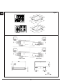
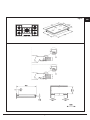
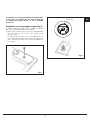
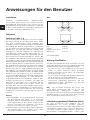
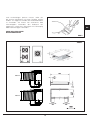
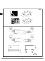
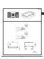
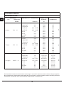
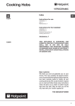
EMG 600 IX
EMG 760 IX
EMG 900 IX
DOMINO GAS
DOMINO WOK
INSTRUCTION MANUAL
Cooking Hob ELECTROGAS
Dear customer,
We thank you and con-gratulate you on
your choice. This new carefully de-signed
product, manu-factured with the highest
quality materials, has been carefully tested to
satisfy all your cooking demands. We would
therefore request you to read and follow these
easy instructions which will allow you to obtain
ex-cellent results right from the start. May we
wish you all the very best with your modern
appliance!
THE MANUFACTURER
Index
Instructions for use
Installation, 4
Use, 4
Maintenance, 4
Instructions for the installater
Installation, 8
Gas connection, 8
Electrical connection, 8
User characteristics, 10
THIS APPLIANCE IS CONCEIVED FOR
DOMESTIC USE ONLY. THE MANUFACTURER
SHALL NOT IN ANY WAY BE HELD
RESPONSIBLE FOR WHATEVER INJURIES
OR DAMAGES ARE CAUSED BY INCORRECT
INSTALLATION OR BY UNSUITABLE, WRONG
OR ABSURD USE.
3
GB
English
DE
Deutsch
GB
Instructions for use
GB
Installation
Gas
All the operations concerned with the installation
(electrical and gas connections, adaptation to type of
gas, necessary adjustments, etc.) must be carried out by
qualified technicians, in terms with the standards in force.
For specific instructions, kindly read the part reserved for
the installation technician.
Use
Gas burners (Fig. 1-3).
The ignition of the gas burner is carried out by putting a
small flame to the upper part holes of the burner, pressing
and rotating the corresponding knob in an anti-klockwise
manner, until the maximum position has coincided with
the marker. When the gas burner has been turned
on, adjust the flame according to need. The minimum
position is found at the end of the anticlockwise rotation
direction. In models with automatic ignition, operate the
knob as described above, pressing simultaneously, the
corresponding push button. For models with automatic/
simultaneous (with one hand) ignition, it is sufficient to
proceed as described above using the corresponding
knob. The electric spark between the ignition plug and
the burner provides the ignition of the burner itself.
After ignition, immediately release the push-button and
adjust the flame according to need. For models with a
thermoelectric safety system, the burner is ignited as in
the various cases described above, keeping the knob
fully pressed on the maximum position for approximately
3/5 seconds. After releasing the knob, make sure the
burner is actually lit.
Fig.1
wok
fast
semifast Ø 14-20
auxiliary* Ø 10-14
Ø 20-32
Ø 20-26
*with reduction grid
Maintenance Gas/Electrical
Prior to any operation, disconnect the appliance from
the electrical system. For long-life to the equipment, a
general cleaning operation must take place periodically,
bearing in mind the following:
- the glass, steel and/or enamelled parts must be
cleaned with suitable non-abrasive or corrosive
products (found on the market). Avoid chlorine-base
products (bleach, etc.);
- avoid leaving acid or alkaline substances on the
working area (vinegar, salt, lemon juice, etc.).
- the wall baffle and the small covers (mobile parts of
the burner) must be washed frequently with boiling
water and detergent, taking care to remove every
possible encrustation. Dry carefully and check that
none of the burner holes is fully or partially clogged;
N.B.:
- we recommend the use of pots and pans with a
diameter matching that of the burner, thus preventing
the flame from escaping from the bottom part and
surrounding the pot
- do not leave any empty pots or pans on the fire
- do not use any tools for grill-cooking on Crystal hobs.
When cooking is finished, it is also a good norm to
close the main gas pipe tap and/ or cylinder.
N.B. - Cleaning of the taps must be carried out by
qualified personnel, who must be consulted in case of
any functioning anomaly. Check periodically the state
of conservation of the flexible gas feed pipe. In case of
leakage, call immediately the qualified technicians for
its replacement.
Important
a) on floors with thermoelectric protection do not keep
the ignite button pushed for more than 15 seconds. If
the burner has not ignited after 15 seconds, open the
door of the room and wait at least one minute before
making a further attempt.
b)on floors without protection, should the burner flame go
out close the corresponding gas cock and wait at least
one minute before making any attempt to ignite it.
Maintenance vitroceramic surface (Fig. 3)
First of all remove stray food bits and grease drops from
the cooking surface with the special scraper (fig. 4).
Then clean the hot area as best as possible with SIDOL,
4
STAHLFIX or other similar products with a papertowel,
then rinse again with water and dry with a clean cloth.
Pieces of aluminum foil and plastic material which
have inadvertently melted or sugar remains or highly
sacchariferous food have to be removed immediately
from the hot cooking area with the special scraper (fig.
4). -This is to avoid any possible damage to the surface
of the top. Under no circumstances should abrasive
sponges or irritating chemical detergents be used such
as oven sprays or spot removers.
GB
Fig.3
DO NOT USE STEAM CLEANERS
Fig.2a
650
30 mm.
40 mm.
5
Fig.2b
GB
4 2 3 1
5 4 3 2 1
FRONT FIXING
REAR FIXING
6
Fig.2c
2
4
3
5
1
5 4 3 2 1
7
GB
Instructions for the installer
GB
Installation
This appliance is not provided with a combu-stion
product discharge. It is recommended that it be
installed in sufficiently aerated places, in terms of the
laws in force. The quantity of air which is necessary for
combu-stion must not be below 2.0 m3/h for each kW of
installed power. See table of burner power.
Fig. 4
Positioning (Fig. 2)
ISO 7/1
ISO 228/1 (FR)
Electrical connection (Fig. 5)
The appliance can be fitted into a working area
as illustrated on the corresponding figure. Before
positioning the hob, fit the seal X around the entire
periphery of the hole cut in the worktop.
Prior to carrying out the electrical connection, please
ensure that:
• the plant characteristics are such as to follow what is
indicated on the matrix plate placed at the bottom of
the working area;
• that the plant is fitted with an efficient earth connection,
following the standards and law provisions in force. The
earth connection is compulsory in terms of the law.
Should there be no cable and/or plug on the equipment,
use suitable absorption material for the working
temperature as well, as indicated on the matrix plate.
Under no circumstance must the cable reach a
temperature above 50°C of the ambient tempera-ture.
If connecting directly to the mains power supply, fit
a multi-pole switch of a suitable size for the rated
capacity with a clearance distance which completely
disconnects the power line under overvoltage category
III conditions, consistently with the rules of installation
(the yellow/green earth wir must not be interrupted). The
plug or omnipolar switch must be easily reached on the
installed equipment.
Gas connection (Fig. 4)
Connect the appliance to the gas cylinder or to the
installation according to the prescribed standards
in force, and ensure beforehand, that the appliance
matches the type of gas available. Otherwise, see
“Adaptation to various types of gas”. Furthermore,
check that the feed pressure falls within the values
described on the table: “User chacteristics”.
Rigid/semi rigid metal connection Carry out the
connection with fittings and metal pipes (even flexible
pipes) so as to obtain counter stress the inner parts of
the appliance.
N.B. - when the installation has been carried out, check
the perfect sealing of the entire connection system, by
using a soapy solution.
Fig. 5
8
To avoid all risk, if the power cable becomes damaged,
it must only be replaced by the manufacturer, by
an authorised service centre, or by a qualified
electrician.
GB
wok C3 only
Adaptation to various types of gas (Fig. 6)
Should the appliance be pre-set for a different type of
gas than that available, proceed as follows:
• replace the injectors (Fig. 5) with the corresponding
type of gas to be used (see table “Uses
characteristics”).
• to adjust to the minimum, use a screwdriver on the
screw placed on the tap (Fig. 6) after turning the tap
to its minimum position. For LPG (butane/propane)
screw tight
Fig. 6
Fig. 7
9
user characteristics
gas burners
burner
ø injectors
pressure mbar
nominal
Norm.
1/100 mm
liquefied gas
G20
20
G30/G31 28-30/37
consumption
W
fast
129
3000
286
semifast
101
1750
167
auxiliary
natural gas
thermal capacity
77
1000
95
wok-DUAL
63A - 121B
3500
333
wok-DUAL
63A - 140B
4250
405
wok 3
141
3500
333
wok 3
150
4000
381
wok MW
140
3500
333
wok 4
141
3500
333
fast
87
3000
218
semifast
66
1750
127
auxiliary
50
1000
73
wok-DUAL
37A - 90B
3500
254
wok-DUAL
37A - 97B
4250
309
wok 3
94
3500
254
wok 3
102
4000
291
wok MW
93
3500
254
wok 4
96
3500
254
l/h
feed
type
g/h
GB
The manufacturer declines all responsibility for possible inaccuracies contained in this pamphlet, due to printing or
copying errors. We reserve the right to make on our own products those changes to be considered necessary or useful,
without jeopardizing the essential characteristics.
10
Einbaukochgerät elektro-gas
Sehr geehrter Kunde,
wir danken Ihnen und beglückwünschen uns
für Ihre Wahl. Dieses neue Produkt, sorgfältig
entworfen und mit erstklassigen Materialien
hergestellt, wurde genau geprüft um alle Ihre
Forderungen an ein perfektes Kochen zu
erfüllen. Wir bitten Sie deshalb die einfachen
Anweisungen zu lesen und einzuhalten, damit
von der ersten Anwendung an ausgezeichnete
Ergeb-nisse erreicht werden können. Mit
diesem modernen Apparat wünschen wir
Ihnen das Beste.
DER HERSTELLER.
Inhaltsverzeichnis
Anweisungen für den Benutzer
Installation 12
Gebrauch 12
Wartung 12
Anweisungen für den Installateur
Installation 16
Gasanschluß 16
Elektroanschluß 16
Technische Daten 18
DIESES
PRODUKT
IST
ALS
HAUSHALTSGERÄT
GEDACHT.
FÜR
SCHADEN AN SACHEN ODER PERSONEN,
DIE AUF FALSCHE INSTALLATION BZW.
UNGEEIGNETEN
GEBRAUCH
ODER
MISSBRAUCH ZURÜCKZUFÜHREN SIND,
ÜBERNIMMT DER HERSTELLER KEINERLEI
VERANTWORTUNG.
11
GB
English
DE
Deutsch
DE
Anweisungen für den Benutzer
Installation
DE
Gas
Sämtliche
Installationsarbeiten
(Elektroanschluß,
Gasanschluß, Anpassung an einen anderen Gastype,
darauffolgende Einstellun-gen, usw.) müssen laut der
geltenden Vorschriften durch Fachpersonal ausgeführt
werden. Für die spezifischen Anleitungen verweisen wir
an den dem Installateur vorbehaltenen Teil.
Gebrauch
Gasbrenner (Abb. 1-3)
Zur Anzündung des Gasbrenners eine Flamme gegen
die kleinen Löcher an der Brennstelle halten, wobei
man den entsprechenden Knopf entgegen dem
Uhrzeigersinn bis zur Großstellung dreht und gedrückt
hält. Sobald der Brenner angezündet ist, Gasflamme
auf die gewünschte Stellung regeln. Die Kleinstellung
befindet sich am Ende der Drehung entgegen dem
Uhrzeigersinn. Bei den Modellen mit automatischer
Anzündung den Knopf wie oben beschrieben bis zur
Kleinstellung drehen, wobei man gleichzeitig auf das
dafür bestimmte Anzündungsknöpfchen drückt. Bei
den Modellen mit automatischer/simultaner Zündung
(einhändig) nur den entsprechenden Bedienknopf wie
oben beschrieben betätigen. Die elektrische Entladung
zwischen diesem Element und dem Brenner verursacht
die Anzündung der gewünschten Brennstelle. Sobald
der Brenner an ist, den Knopf sofort loslassen und die
Flamme nach Wunsch regeln. Die Brennerzündung bei
den Modellen mit thermoelektrischer Sicherheit erfolgt
wie in den oben beschriebenen Fällen, den Bedienknopf
dabei auf max. Leistungsstufe ca. 3/ 5 Sekunden bis
zum Anschlag gedrückt halten. Wenn der Knopf wieder
losgelassen wird, kontrollieren Sie, daß der Brenner
angezündet bleibt. Es wird empfohlen, Töpfe mit dem
richtigen Durchmesser im Verhältnis zur Größe der
Brennstelle zu verwenden, um zu vermeiden, daß die
Flammen um den Topf herum züngeln. Lassen Sie
die Kochstellen nicht mit leeren Töpfen eingeschaltet;
verwenden Sie keine Grillgeräte auf Crystal Kochstellen.
Es wird empfohlen, den Haupthahan der Gasleitung
und/oder der Gasflasche nach dem Kochen immer zu
schließen.
Abb.1
wok schnell
halbschnell Ø 14-20
hilfbrenner*
Ø 20-32
Ø 20-26
Ø 10-14
*mit Reduziergitter
Wartung Gas/Elektro
Vor jeder Wartungsarbeit das Gerät ausschalten. Für eine
lange Lebensdauer des Geräts muß es unbedingt regelmäßig
gründlich gereinigt werden. Dazu folgendes beachten:
- Die Teile aus Glas, Stahl und/oder Email müssen mit
milden, im Handel erhältlichen Mitteln gesäubert
werden. Verwenden Sie auf keinen Fall chlorhaltige
Mittel (Bleichmittel, usw.).
- Lassen Sie keine säurehaltigen oder alkalischen Speisereste
(Essig, Zitronensaft, usw.) auf der Arbeitsfläche;
- Die losen Teile der Brennstellen müssen in warmem
Seifenwasser regelmäßig gewaschen und gut
abgetrocknet werden. Kontrollieren Sie, daß die
Löcher nicht verstopft sind.
N.B. - Das eventuelle Schmieren der Hähne muß
immer durch Fachpersonal und nur im Fall von
Betriebsstörungen
vorgenommen
werden.
Der
Gasschlauch muß auf seinen guten Zustand regelmäßig
kontrolliert werden. Im Fall von Lecken den Schlauch
durch Fachpersonal sofort ersetzen lassen.
Wichtig
a)Bei Kochfeldern mit thermoelektrischer Sicherung
die Einschaltung nicht länger als 15 Sekunden
betätigen. Wenn sich der Brenner nach 15 Sekunden
nicht eingeschaltet hat, dann öffnen Sie die Tür des
Raumes und warten Sie mindestens eine Minute
bevor Sie erneut das Einschalten versuchen.
b)Bei Kochfeldern mit Flammenlöschung eines Brenners
den entsprechenden Hahn schließen und mit dem
Einschalten mindestens eine Minute warten.
Instandhaltung glaskeramik Oberflache (Abb. 3)
Vor allem Essensreste und Fettspritzer von der
Kochoberfläche mit einem Schaber entfernen.
Danach die warme Fläche mit Sidol oder Stahlfix und
Küchenpapier säubern, dann mit Wasser abwaschen
und einem sauberen Lappen trocknen. Spuren von
Aluminiumfolie, Plastikgegenständen, Zucker oder
12
stark zuckerhaltigen Speisen müssen sofort von
der warmen Kochfläche mit einem Schaber entfernt
werden um mögliche Schäden der Plattenoberfläche
zu vermeiden. Auf keinen Fall Schwämme oder
Scheuerlappen verwenden; den Gebrauch von
aggressiven chemischen Putzmitteln wie Fornospray
oder Fleckenreinigern vermeiden.
DE
KEINE HOCHDRUCKREI
NIGER VERWENDEN
Abb.3
Abb.2a
650
30 mm.
40 mm.
13
Abb.2b
DE
4 2 3 1
5 4 3 2 1
FRONTSEITIGE BEFESTIGUNG
RÜCKSEITIGE BEFESTIGUNG
14
Abb.2c
DE
2
4
3
5
1
5 4 3 2 1
15
Anleitungen für den Installateur
Installation
DE
Dieses Gerät ist mit einer Vorrichtung zur Beseitigung der
Verbrennungsgase nicht angeschlossen. Installation und Anschluß
müssen laut den geltenden Vorschriften ausgefürt werden.
Gerät nur in ausreichend belüfteten Räumen und nach den
gesetzlichen Vorschriften aufstellen. Die Menge der benötigten
Verbrennungsluft darf nicht unter 2,0 m3/h pro installierte kW
Leistungseinheit liegen. Siehe Heizleistungstabelle.
Abb. 4
ISO 7/1
ISO 228/1 (FR)
Aufstellung (Abb. 2)
Elektroanschluß (Abb. 5)
Das Gerät ist für den Einbau in einer Ar-beitsfläche
vorgesehen, wie aus der Abbildung er-sichtlich wird.
Vor dem Einsetzen der Kochmulde ist die Dichtung
X auf dem gesamten Umfang des Einbauausschnitts
anzubringen.
Bevor der Elektroanschluß hergestellt wird, versichern
Sie sich:
• ob die Merkmale der Anlage den Angaben des
Kenndatenschilds an der Unterseite der Kochfläche
entsprechen;
• ob die Anlage selbst nach den gesetz! ichen Vorschriften
geerdet ist. Die Erdung ist bindend vorgeschrieben. Falls
das Gerät kein Kabel und/oder keinen Stecker besitzt,
verwenden Sie den Kenndaten und der Betriebstemperatur
entsprechendes Material. Das Kabel darf an keiner Stelle
eine Temperatur erreichen, die mehr als 50°C über der
Raum temperatur liegt.
Für den direkten Netzanschluss muss ein allpoliger
Schalter zwischengelegt werden, der für die auf dem
Typenschild angegebene Last bemessen ist, und
der die Trennung vom Netz mit einer Kontaktweite
gewährleistet, die gemäß den Installationsnormen die
vollständige Abschaltung bei Überspannung Kategorie
III ermöglicht (das gelb/grüne Erdkabel darf nicht
unterbrochen werden). Die Steckdose oder der allpolige
Schalter müssen bei dem instal-lierten Apparat leicht
zu erreichen sein.
Gasanschluß (Abb. 4)
Das Gerät an die Gasflasche oder an das Gasversorgungsnetz
nach den geltenden Vorschriften anschließen und dabei
sicherstellen, daß das Gerät auf den vorhandenen Gastyp
eingestellt ist (wenn es nicht der Fall sein sollte, wird auf das
Kapitel “Anpassung an einen anderen Gastyp” verwiesen).
Man sollte außerdem kontrollieren, daß der Förderdruck den
in Tab. “Technische Daten” angegebenen Werten entspricht.
Anschluß mit Metallanschlußstutzen und röhren, fest/
halbfest Den Anschluß mit Anschlußstutzen und
(ev. flexiblen) Röhren aus Metall so ausführen, daß
die inneren Teile des Geräts nicht belastet werden.
Hinweis: Bei vollendeter Installation muß die gesamte
Anschlußleitung mit einer Seifenlösung auf vollständige
Dichtigkeit überprüft werden.
Abb. 5
16
Falls das Netzkabel beschädigt ist, muss es
durch den Hersteller oder seinen technischen
Kundendienst oder in jedem Fall durch eine
entsprechend qualifizierte Fachkraft ersetzt werden,
um jedes Risiko auszuschließen.
nur wok C3
DE
Anpassung an einen anderen Gastyp (Abb. 6)
Ween das Gerät für einen anderen Gastyp als der vorhandene
ausgelegt ist, ist folgende Vorgehensweise durchzuführen:
• die Düsen (Abb. 5) mit den vorhandenen Gastyp bestimmten
Düsen (siehe Tab. “Technische Daten” ersetzen;
• bei der Einstellung des Mindestwertes, den Hahnhebel
auf das Minimum drehen und die Einstellschraube
am Hahn mit entsprechendem Schraubenzieher
drehen (Abb. 6). Bei Betrieb mit Flüssiggas (Butan- /
Propangas) Einstellschraube fest anziehen.
Abb. 6
Abb. 7
17
TECHNISCHE DATEN
GASBRENNSTELLEN
NOMINAL
Norm.
Naturgas
Naturgas
Flüssiggas
G20
G25
20
20
G30/G31 50
WäRMEBELASTUNG
1/100 mm
VERBRAUCH
W
schnell
129
3000
286
halbschnell
101
1750
167
hilfsbrenner
77
1000
95
wok-DUAL
63A - 121B
3500
333
wok-DUAL
63A - 140B
4250
405
wok 3
141
3500
333
wok 3
150
4000
381
wok MW
140
3500
333
wok 4
141
3500
333
schnell
138
3000
333
halbschnell
107
1750
194
hilfsbrenner
85
1000
111
wok-DUAL
71A - 133B
3500
388
wok-DUAL
71A - 148B
4250
472
wok 3
150
3500
388
wok 3
160
4000
443
wok MW
151
3500
388
wok 4
152
3500
388
schnell
79
3000/2700
218/193
127/112
halbschnell
58
1750/1575
hilfsbrenner
46
1000/900
73/64
wok-DUAL
37A - 76B
3500/3150
254/225
wok-DUAL
37A - 83B
4250/3825
309/274
wok 3
83
3500
255/250
wok 3
92
4000
291/286
wok MW
85
3500
255/250
wok 4
85
3500/3150
254/225
l/h
BRENNERTYP ø DüSENELEMENTE
DRUCK mbar
l/h
TYP
g/h
SPEISUNG
DE
Die Herstellerfirma übernimmt keinerlei Verantwortung für eventuell in dieser Broschüre enthaltene Ungenauigkeiten,
die auf Druckfehler zurückzuführen sind und behält sich das Recht vor an ihren Produkten alle für notwendig erachteten
Änderungen anzubringen, ohne die wesentlichen Eigenschaften zu beeinflussen.
18
ABBINA GERMANY GmbH
www.abbina.de
[email protected]
1.005.53.0